study to develop techniques for a self-organizing … · study to develop techniques for a...
TRANSCRIPT
STUDY TO DEVELOP TECHNIQUES FOR A
SELF-ORGANIZING COMPUTER
Third Quarterly Progress Report
Contract No. NASW-2276
Covering the period
1 January 1972 - 31 March 1972
A/73.
E FILE
Prepared by
Mario R. Schaffner
for
National Aeronautics and Space Administration
https://ntrs.nasa.gov/search.jsp?R=19720018506 2018-09-07T19:48:30+00:00Z
1 - FACTUAL INFORMATION
1.1 The work during this quarterly period has been essentially as
anticipated in the second Quarterly Report. A description is given in
section 2, subdivided in tasks as defined in the previous Quarterly
Report.
In section 3 the work planned for the next period is described.
1.2 Meetings, attendance^ papers
A paper "Structure of a Communication Network and Its Control Com-
puters" with I. Cappetti has been prepared for presentation to the
Symposium on Computer-Communication networks and teletraffic of the
Polytechnic Institute of Brooklyn.
A paper "Abstract Models as a Programing Language" has been
written and submitted for presentation.
During this quarter, attendance has been made to the IEEE Inter-
national Convention and to the Conference on Information Sciences and
Systems of Princeton University.
1.3 Personnel
The personnel active on this contract during the third quarter are:
Prof. Norman A. Phillips, Project Supervisor - Advisory Capacity
Mario R Schaffner 2.2 months
Programmer • in hours
Drafting, clerical and technical assistance 90 hours
Dr. Pauline M. Austin and Spiros G. Geotis of the Weather Radar
Research Project at M.I.T. are also participating in consulting and
advisory capacity for the applications to weather radar.
- 1 -
2. SUMMARY OP THE WORK PERFORMED IN THE THIRD QUARTER
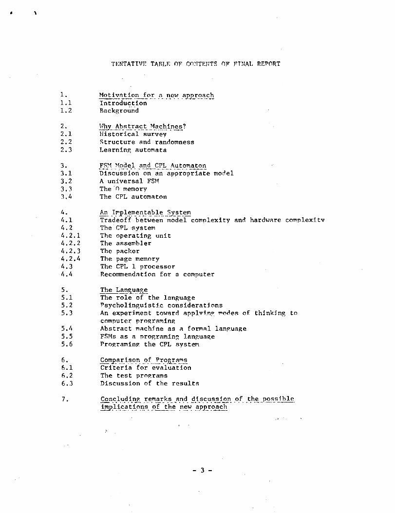
The work under this contract has been subdivided into tasks
labelled according to the chapters in a tentative table of contents
for the Final Report; this table is here repeated and updated.
During the previous quarterly periods, attention was given to
tasks 1, 2, and 3 and an account of the development reached was given
in the corresponding sections of the second Quarterly Report. In this
report, the main points of those tasks, with some additional comments,
are repeated (Sections 2.1, 2.2, and 2.3) as a background to the task
developed during the period referred to in the present report.
During the past three months the main emphasis has been on the
language, and a first draft of the corresponding chapter of the Final
Report is given here (Section 2.5).
- 2 -
TENTATIVE TABLE OF CONTENTS OF FINAL REPORT
1. Motivation for a_ new approach1.1 Introduction1.2 Background
2. Why_ AbA'L1'.3. . chines?2.1 Historical survey2.2 Structure and randomness2.3 Learning automata
3 . Z ? . - . . .3.1 Discussion on an appropriate model3.2 A universal FSM3. 3 The 0 memory3.4 The CPL automaton
4. An Imjplementable .System4.1 Tradeoff between model complexity and hardware complexity4.2 The CPL system4.2.1 The operating unit4.2.2 The assembler4.2.3 The packer4.2.4 The page memory4.3 The CPL 1 processor4.4 Recommendation for a computer
5 . The Language5.1 The role of the language5.2 Psycholinguistic considerations5.3 An experiment toward applyinp: modes of thinking to
computer programing5.4 Abstract machine as a formal language5.5 FSMs as a programing language5.6 Programing the CPL system
6. Comparison _of Pjrograms6.1 Criteria for evaluation6.2 The test programs6.3 Discussion of the results
7. Concluding remarks and discus_sjjyp of the possible.implications of_jthe new approach
- 3 -
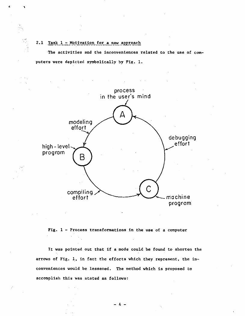
2.1 Task 1 - Motivation for a new approach
The activities and the inconveniences related to the use of com-
puters were depicted symbolically by Fig. 1.
modelingeffort
high- levelprogram
compilingeffort
processin the user's mind
debuggingeffort
machineprogram
Fig. 1 - Process transformations in the use of a computer
It was pointed out that if a mode could be found to shorten the
arrows of Fig. 1, in fact the efforts which they represent, the in-
conveniences would be lessened. The method which is proposed to
accomplish this was stated as follows:

Given an activity A to be produced, described in what-
ever form,
rather than developing an algorith L, executable by a
real machine B (or alternatively translatable by a compiler
C of B) such that B (or C + B) produces A,
develop an abstract machine M such that M produces A
as its natural response; then describe M in a form m acceptable
by a given loose real system S, in order for S to become a
real machine equivalent to M.
A loose system S can be thought of as an ensemble of operating and storage
elements that can be organized to form desired operational networks. From
automata theory viewpoint, it can be regarded as a giant, unmanageable,
finite-state machine with a very large number of states and input signals.
The state diagram of such a machine, which we call the total state
diagram, is practically undescribable. Now, the input signals are
divided into two categories which we call problem inputs and p inputs.
For each set of values of the p inputs, a particular "component" of the
total state diagram is selected, while all the rest disappear (Cfr.
Minsky, 1967, sections 2.4 and 2.5). Such a component can be regarded
as a specific computation. In dealing with this component, the user
needs to be concerned only with the few problem inputs and the few
states of that component.
The description m (that we can see as the program for the loose
system S) consists of the management of those p inputs. The key point
is that in this approach the p inputs are not prepared in terms of a
- 5 -
given real machine that has to simulate the desired activity A: the
management of the inputs p results, almost completely, from the process
of modeling the activity A in the form of an abstract machine M. The
words "almost completely" account for the difference between M and m,
due to possible limitations of the system S. In other words, the user
is concerned only with the problem he is dealing with, in the terms he
finds more appropriate for that specific problem. At the end of the
construction of the abstract machine M, the management of the p inputs
results almost completely established, without need for the user to
think of any given computer.
2.2 Task 2 - Why Abstract Machines?
The justification for having chosen abstract machines was accounted
in the Second Quarterly Report (Section 2.2). Further discussion is
presented here from a viewpoint of interest for the issue of the language
to be considered in Section 2.5.
In past decades there was strong interest in comparing the working
of biological neural systems and of computers, at that time in their
first emerging. McCulloch and Pitts (1943) made the first well known
work. Then von Neumann worked increasingly in analyzing similarities
and diversities between brain and computers (1948, 1958, 1966). Clear-
ly, he was expecting to develop a general theory of automata that
could be a useful model both of the brain and computer functioning.
Today, on the one hand, new specific technologies have been developed
for the implementation of computers. Computers themselves have become a
new discipline with its specialists, theories, and jargons. On the other
- 6 -

hand, continuous work in neurology has increased the realization of
the complexity and multifacets of the neural system. As the two fields
developed separately, there has been a decreased interest in comparing
approaches and techniques used by the biological system with those
appropriate for the man-made systems.
As a matter of fact we do not need a system compatibility between
biological organisms and computers. Vie do not envision, for computer
use, the application of electrodes to people for establishing direct
communication with man-made devices. The communication we seek is
through modes of expression with which human beings are normally familiar,
e.g., languages and visual images.
In the last decades, automata theory has become of interest to other
human fields besides neurology, namely, psychology and linguistics.
In theory of thinking, developmental structures constitute new powerful
models. (Cfr. Handler, 1964: Piaget, 1950; Flavell, 1963; Miller, 1964).
These models, of completely independent formation, find interesting
parallelisms in automata theory. In linguistics, automata models give
new possibilities for analyzing languages (Blumenthal, 1970: Chomsky,
1957, 1965).
It appears of interest now to compare the working of computers with
the models used in psychology and linguistics. The aim is to reach a
better compatibility of expression and communication between human users
and computers.
- 7 -
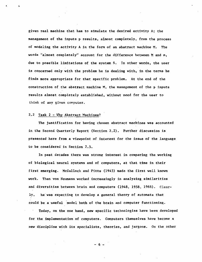
2.3 - Task3 : FSM model and CPL automaton
The basic abstract machine - called FSM - to be used for model-
ing the processes is repeated in Fig. 2.
X X
[IFTR],
[IFTR
z z z . . . . z z
Fig. 2 - The basic automaton
A read-only tape contains a finite string of input symbols x, from
an alphabet A. A "blackbox" contains a finite set Y of symbols y
(internal variables) from A and is capable of assuming a finite set S
of internal configurations (networks of logical elements capable of
reading the symbols of A in some coding) called the states of the auto-
maton. A state s is defined as a quadruplet (I, F, T, R), where I
(input prescription function) is a mapping that makes available to the
- 8 -

black box a subset X of the symbols x in the input tape: F (data trans-
formation function) is a mapping of X Y into a new set Y; T (trans-f
ition function) is a mapping of X Y into the next state in S; and R
(routing function) is a mapping of a subset of Y into a string of out-
put symbols z in a write-only output tape.
The time is quantized in discrete moments i. The process is
modeled by means of the two recursive functions (1) and the related
state diagram.
(1)
The work of the automaton can be visualized in Fig. 2 as an activation
of one of the k quadruplets at each moment i.
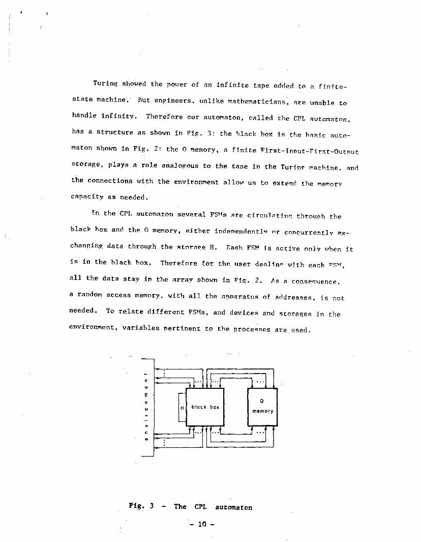
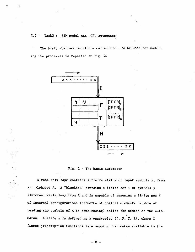
Turing showed the power of an infinite tape added to a finite-
state machine. But engineers, unlike mathematicians, are unable to
handle infinity. Therefore our automaton, called the CPL automaton,
has a structure as shown in Fig. 3: the black box is the basic auto-
maton shown in Fig. 2: the 0 memory, a finite First-Innut-First-Outnut
storage, plays a role analogous to the tape in the Turin? machine, and
the connections with the environment allow us to extend the memorv
capacity as needed.
In the CPL automaton several FSMs are circulating through the
black box and the 0 memory, either independent]^ or concurrently ex-
changing data through the storage H. Eash FSM is active onlv when it
is in the black box. Therefore for the user dealing with each FSM,
all the data stay in the array shown in Fig. 2. As a consequence,
a random access memory, with all the apparatus of addresses, is not
needed. To relate different FSMs, and devices and storages in the.
environment, variables pertinent to the processes are used.
Pig. 3 - The CPL automaton
- 10 -
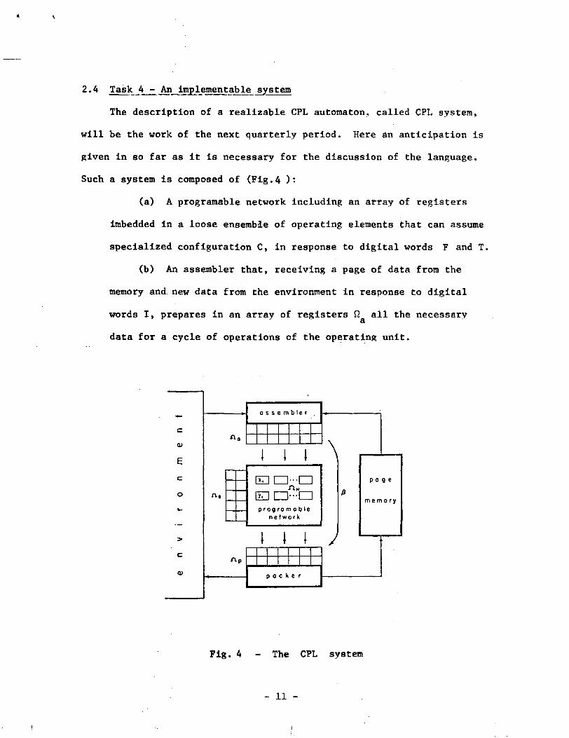
2.4 Task 4 _-_ An implementabde system
The description of a realizable CPL automaton., called CPL system,
will be the work of the next quarterly period. Here an anticipation is
given in so far as it is necessary for the discussion of the language.
Such a system is composed of (Fig.4 ):
(a) A programable network including an array of registers
imbedded in a loose ensemble of operating elements that can assume
specialized configuration C, in response to digital words F and T.
(b) An assembler that, receiving a page of data from the
memory and new data from the environment in response to digital
words I, prepares in an array of registers ft all the necessaryCl
data for a cycle of operations of the operating unit.
c
O)
E
c
o
<u
a s s e m b l e r
1 1 1
prog ro m a b len e t w o r k
p a c k e r
\
t i l /
p a g e
m e m o r y
Fig. 4 - The CPL system
- 11 -
(c) A packer that, receiving a page of data into a
register array ft , at the end of each cycle of the operating unit,s
routes some data to the environment in response to digital words
R, and some to the memory.
(d) A memory with a loose structure capable of holding a
large number of pages. The memory receives one page at a time
from the packer when requested, and furnishes one page at a
time to the assembler again when requested.
A process to be performed is described as an FSM. The FSM des-
cription is stored in the form of a page of digital data. As the page
circulates through the assembler, operating unit, packer, and page
memory, the process is executed.
Main features of the system are:
(i) A mapping is implemented between functions F and configurations
C, in accordance with the correspondance between logical behaviors
and logical networks discussed in the Second Quarterly Report,
(ii) A loose structure similar to that of written pages is used
for organizing in an independent manageable set of symbols all
the information necessary for the performance of an FSM.
- 12 -

2.5 Task 5 - The language
2.5.1 The role of the language
As symbolized in Fig. 1, typically, three languages are involved
in the use of computers: (1) a spoken language, typically mixed with
expressions of mathematical languages, for describing a process origin-
ated by some human mind; (2) a high-level language for modeling that
processes in a rigorous form acceptable by the available computing
system (hardware plus software): and (3) a machine-language for actually
instructing the computer to execute the process.
These three languages are independent. The process originator,
during the description of his process, does not think of the other two
languages. Even if the originator himself later programs the computer,
he does not use, say, Fortran statements or machine instructions in
delineating the process. He may have continuously in mind constraints
and possibilities of the computer he is going to use, but he does not
use computer languages in conceiving and clarifying the process he is
dealing with. Several are the reasons for this. The elements of com-
puter languages are too rigid for coping with the flexible, loose,
self-adapting ways of human minds in search of a solution for a problem.
Any expression of computer language requires that all the details be
already established; clearly this is not the situation when one is
constructing a process. All these points are highly relevant to our
study and will be recalled repeatedly in the following.
The high-level language is used by the programer and, once chosen,
does not have any relation either with the originator language or with
the machine language. Each high-level language is developed independently,
with the intention to be practical for particular types of processes, or
of users.
- 13 ~
The machine-language is used by the computer, and it does not
have any connection with the other two languages. Each computer has
its own machine language as a consequence of its design.
It is legitimate to wonder if three languages, foreign among
themselves, are really necessary to communicate with a computer. As
it can be seen in Sammet (1969), or in the most recent panel dis-
cussion on the subject (IEEE, 1972), the present trend is to accept
this situation and to develop a set of the most appropriate high-level
languages and to look for some standardization in the machine languages.
The optimists hope that in so doing, each user will find a high-level
language particularly efficient for his problem, while all these
different languages will tend to have similarities in their structure.
It is not clear if this hope is feasible or there is a contradiction.
The pessimists simply worry about the proliferation of languages.
Let us consider the opposite approach: to search for possible
universals in the expressions of the process originators in order to
form a single high-level language appropriate for the different prob-
lems and users. In other words, rather than to follow the different
jargons proliferating for the different problems, let us come back to
the roots, if such there are, common to all, or majority of problems
and users.
There are justifications for considering such an approach. An
elementary part of mathematics, the arithmetic operations, are used,
like universal notions, in all applied fields. We are all trained to
that, in the elementary schools of all the world. As a matter of fact,
- 14 -

the universality of general purpose computers is based on their capa-
bility to execute the arithmetic operations. But the monstrosity into
which software has grown shows that those universals alone are not
capable of implementing our aim.
In philosophy also the perennial aim has been to seek universals
in nature and human thoughts. More recently the same aim is exhibited
by psychology and linguistics. This suggests that our search should
not be confined to mathematics and engineering, but should share also
the efforts made in other disciplines.
The language which is being developed is based on the premise that
abstract machines constitute a language common to users and computers
(see discussion in the second Quarterly Report). More precisely, that
abstract machines play the role of machine languages, high-level
languages, and be closely related to the process image in the user's
mind. It has already been shown (Schaffner, 1971 ) that a form of
abstract machine suitable to be a high-level model of processes can at
the same time be an actual machine program for a particular type of
computer. The experience gained with a first computer of this type
confirms the practicality of the approach. More insight is needed on
the claimed closeness between abstract machines and process image in
the user's mind.
2.5.2. Psycholinguistic considerations
If a programing language is intended for use by nonspecialists,
its psychological aspects have to be considered no less that its formal
aspects. Spoken languages, which developed as a result of human needs
- 15 -

and characteristics, are undoubtedly compatible with these character-
istics. Conversely, artificial languages need conscious attention in
order to be appropriate to the psychological characteristics of the
users. The first programing languages completely concentrated on
making possible the use of existing computers, and few concessions could
be made to psychological considerations. The present level of technology
should allow much higher priority to the user's dispositions.
Two fields of psychology are highly relevant to a programing language,
structures of thinking and of languages. A survey from a psychological
viewpoint of the studies of thinking, from Aristotle's images to the
present is given in Handler (1964); mathematical modeling is discussed
in Miller (1964); and a modern view of developmental structures can be
found in Flavel (1963). A historical review of psychological studies
of language can be found in Blumenthal (1970), and a modern approach of
generative grammar is given by Chomsky (1957, 1965).
In the second Quartely Report (Section 2.2), similarities
between abstract machines and models of the brain work were noted.
Now we find analogies with models used in psychology and linguistic.
We can not escape pointing out that the developmental
structures of modern psychology and the syntactic structures
of modern linguistics are types of self-adapting finite state machines,
while similar models are suggested in our work for programing computers.
Functions F and T of our modeling, in a sense, have a similarity with the
grouping of mental.operations of Piaget (1950). One may be tempted to
conjecture that the greater insight achieved in psychology by using develop-
mental structures rather than association schemes might have a parallel in a
- 16 -

greater efficiency that could he ohtnined in computer programing hv usin?
abstract machine models rather than conventional command languages.
Even without becoming involved in thought theory, it is clearly
recognizable that a process can be represented more easily by means of
the multidimensional structure of an abstract machine than by means of
an array of symbols as in conventional programing languages. It is
common experience that a sketch is more easily understood than a set of
formal phrased sentences. Therefore it seems likely that a nonprofessional
user will need less effort to describe and read a process in the form of
an abstract machine than in the form of formal sentence description.
It is interesting to observe that before any development of automata
theory, in mathematics, Turing (1936) needed an abstract machine in
order to ascertain the computability of functions, and in engineering,
Kutti (1928) used abstract machines to work on the operation of complex
telephonic systems. Referring to the processing capability of the human
brain, von Neumann (1948) argued that such a function as the recognition
of visual analogies perhaps could not be described in sentences, while
it is actually performed by the finite neural machine. Then he suggested
(1966) that for complex automata their description should be simpler
than a symbolic description of their behaviour. He was referring to mathe-
matical complexity; here we are interested in the subjective complexity
as felt by a user. While it is reasonable to think that a mathematical
complexity has a counterpart in the subjective complexity, we do not
have a basis for the reverse. The approach taken here on this subject
will be discussed under task 6, and consists of comparing (under certain
criteria) test processes described (1) by means of conventional procedural
- 17 -

programing-languages, and (2) by means of the description of abstract
automata modeling the process.
Echoing Whorf's (1956) hypothesis that the structure of the
language influences the manner in which humans understand reality and
behave, one can simply mention the possible influence on those who use
computers of changing from a command language to that of abstract
machines. At least, when programing in the form of abstract machines,
the user will not feel himself to be a slave of the computer since he
will have designed its characteristics.
2.5.3. _An .experiment toward applying modes of thinking to computerprograming
A first experiment has been undertaken on determining computer
characteristics in accordance with natural inclinations of general users.
A specific computer feature has been chosen, one which we feel is of such
a general nature that it can be considered, a priori, related to a natural
feature of our thinking: the transition between states. Undoubtedly,
the notion of transition between items, times, actions, situations,
places, etc., is familiar and "natural" for everyone, independently of
the training, specialization and professional activity. A variety of
people of different activity and age are being interviewed in order to
collect patterns, usages, frames in the notion of transition, and the
results have been considered for defining the modes in which transitions
can be organized in a GPL system.
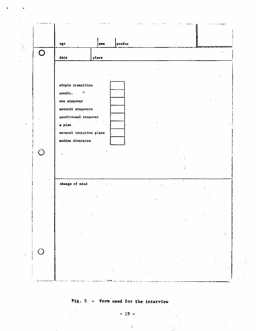
2.5.3.1. The interview
The form of Fig. 5 is used to facilitate the extraction of the
wanted information from the interviewed people. In order to bring
the interviewee to the issue, transition is presented first as physical
- 18 -
O
I O
i O
age sex profes
date place
simple transition
condlt. "
one stopover
several stopovers
conditional stopover
a plan
several tentative plans
eudden diversion
change of mind
Fig. 5 - Form used for the interview
- 19 -

transfer from one place to another. Eight modes (upper part of the
form) are presented as applicable to planning a trip, for business or
pleasure. The relative applicability of these modes is asked and
results recorded as ordered numbers in the form. At this time the
person being interviewed is already "in" the notion of transition, and
sometimes is able to mention some other ways of looking at it, ways
that are transcribed if different from the eight examples given.
Then the notion of transition is presented in the sense of "chang-
ing mind", "changing situation", "changing status". The different ways
of reacting and sayings of the interviewed are interpreted and if an
interesting pattern of the transition appears it is noted in the second
half of the form.
The population interviewed includes students, professionals in
different fields, and people in a variety of occupations; their ages
range from 11 years to mature age. Some distributions of the different
viewpoints will be derived from the data. The following is a sample of
some interesting expressions obtained.
T A B L E 1
1. I will go there, and then I will see.
2. I will go to C, and I might stop in B.
3. I will stop there for a certain time.
4. Temporary block.
5. Several plans performed sequentially.
6. Cancelling the plan, and making another.
7. Discuss this, before you forget.
8. If I think many things at a time, the efficiency decreases.
- 20 -
2.5.3.2. _Featu 5!L ?f_t!]!?_tEfl!Lsi.t*.?n
From the material gathered with the interviews, and from the
experience of programing the CPL 1 processor, features for the trans-
ition between states have been defined. Some of these have already
been implemented in the CPL 1 processor, some were already planned,
some are new extensions of the previous ones, and some are new forms
of transitions in an FSM.
The effectiveness of the transition function T in describing a
complex process in a simple form had already been recognized. The work
done in connection with the reported interview has further confirmed
that effectiveness, and demonstrated, at least for this case, the possi-
bility and the convenience of modeling computer features after common
features of people thinking.
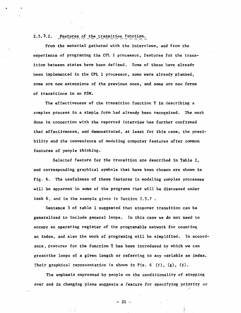
Selected feature for the transition are described in Table 2,
and corresponding graphical symbols that have been chosen are shown in
Fig. 6. The usefulness of these features in modeling complex processes
will be apparent in some of the programs that will be discussed under
task 6, and in the example given in Section 2.5.7 .
Sentence 3 of table 1 suggested that stopover transition can be
generalized to include general loops. In this case we do not need to
occupy an operating register of the programable network for counting
an index, and also the work of programing will be simplified. In accord-
ance , features for the function T has been introduced by which we can
prescribe loops of a given length or referring to any variable as index.
Their graphical representation is shown in Fig. 6 (f) , (g) , (i) .
The emphasis expressed by people on the conditionality of stopping
over and in changing plans suggests a feature for specifying priority or
- 21 -

T A B L E 2 - Selected Transitions
(a). No prescription of any sort for T function means that the machineremains in the present state (until some action from the outside ofthat FSM occurs). In the state diagram, this case is represented byabsence of any arrow emerging from the circle representing that state,Fig. 6 (a).
(b). Unconditional transition to the state with the next label (inthe natural numerical order). Note that this is the simplest codedtransition, no state labels need to be indicated. The adopted graphicalrepresentation consists of drawing adjacent the circles representingthe states, Fig. 6 (b).
(c). Unconditional transition to state h. This prescription needssimply the state label h. Its graphical representation consists of anarrow pointing to state h, Fig. 6 (c) . (Each specific example in Fig. 6is shown in heavier lines).
(d). Transition to different states depending on conditions. The Tfunction and the related state labels need to be prescribed. Thegraphical representation consists of several oriented arrows emergingfrom the state, Fig. 6 (d).
(e). Forced transition (produced as a consequence of actions by part ofsome other FSM). No prescription is made in this FSM. The graphicalrepresentation consists of a dashed arrow, Fig. 6 (e). This symbol isusually used also to indicate the starting state.
(f). Go to state h and stay there for n cycles (then the transitionprescribed in state h will act). The prescription needs a code, thelabel h and the value n. The graphical representation consists of anarrow with open head where the value of n is written, Fig. 6 (f).
(g). Stay in the present state for n cycles (then the other prescriptionswill act). The prescription needs a code and the value n. The graphicalrepresentation consists of an arrow looping into the state with the valueof n written inside, Fig. 6 (g).
(h). Go to state h stopping over sates 1, m, . . . (stopover transition).The prescription consists of the multiplicity of state labels in anestablished order. The graphical representation consists of a jaggedarrow with notches pointing to the states where stop is made, Fig. 6 (h).
(i) . As in h, but staying in the stopover states for assigned numbers ofcycles. The prescription is as in h with added number of cycles. Thegraphical representation is as in h, with the number of cycles writtenin the notches , Fig. 6 (i).
( cont. )
- 22 -
(j). Priority is assigned to one or more transition branches. Prioritymeans that that branch (if chosen by the function T) will occur first,regardless of other conventions. The prescription consists of a codeadded to the description of that branch. The graphical representationconsists of a dot superimposed to the arrow representing that branch,Fig. 6 (j).
(k). Transfer of page. This feature is used when the page movement iscontrolled by function T, rather than following the automatic circulation.The prescription consists of a code added to the description of thebranches for which the page remains in operation. The graphical repre-sentation consists of a square added to those branches, Fig. 6 (k) .
(1). End of page. This transition produces the disappearing of the page.It is described as a special state label. It is represented graphicallyby a triangle, Fig. 6 (1).
- 23 -

o
(a)
O
(c)
(e)
(f) (g)Fig. 6 - Symbols for transitions ( cont. )
- 24 -

(0
( j )I
6
(K)
oo
) '
Q (J!)Fig. 6 - ( cont.) Symbols for transitions
- 25 -

conditions on several options for a transition. Tn accordance, sinnle
hardware features have been devised by which these possibilities can be
prescribed as forms of the function T. Corresponding symbols for the
state diagrams are in Fig. 6 (j) .
The feature of the priority allows the mechanization of a variety
of rules. The following, that will be used often, refers to the stop-
over transitions. When the states connected with priority transition
are adjacent (in the state-label order), the next destination of a
stopover transition will be reached at the end of the priority trans-
itions, as in the example 3 of Fig. 6 (j). When the states connected
with priority transition are not adjacent, the occurrence of that
transition cancels every previous stopover prescription.(ex. A of Fij». 6 j).
Transitions f and g of Table 2 and transition h in the second
example given in Fig. 6 (h) produce the same thing. But this redundancy
is in fact a flexibility which eases the programing. In the case of
transition g, the prescription of staying is made once and it holds for
all the transits through that state. In the case of transitions f
the stay can be different for different arrivals to that state. In
the case of transition h, the stay can be different in accordance with
events occurring in that state.
Note that two symbols of forced transition are used, Fig. 6 (e):
a dashed arrow connecting two states, if the forced transition is
supposed to occur when the machine is in that indicated state; a notched arrow,
if the forced transition may occur when the machine is in any one of several
different states.
- 26 -
2.5.A - Abstract machine as a formal language
Formal language theory defines a language as a set of strings of
symbols over a finite alphabet. Such a broad definition covers natural
languages, programing languages, and certain mathematical systems studied
in automata theory. The approach taken in formal languages also clari-
fies how a language makes it possible to express infinite information
(the enumerable infinite set of strings) with finite means (the finite
alphabet and grammar).
Our abstract machines as a language are multi-dimensional entities
(as opposed to the linear strings of symbols), with a grammar left open
(in a sense) to the imagination of the user. While it is expected that
such a language, used as a programing language, can be brought under
said definition of formal languages, there is not yet an available
theoretical treatment. This fact does not limit the use of our language.
In fact, we are using a very simple type of abstract machines, that is
readily translatable in a normal string of symbols.
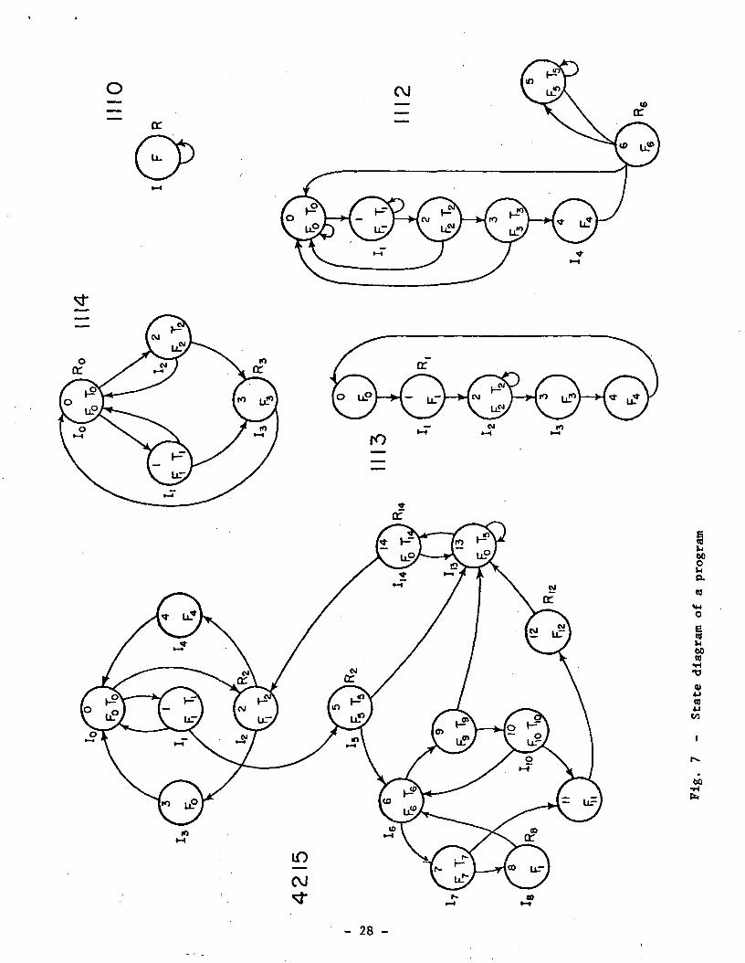
As an example, an actual program, referred to under task 6, is
shown in Fig. 7 in its state diagram form. Five FSMs can be distinguished,
all engaged concurrently on the same task. The constituent elements
of such a program are: states, transitions, I, F. T, R's and data.
The program of Fig. 7 can be transformed into the string of symbols,
(2), by very simple rules. The items constituting the FSMs are indicated
sequentially, each state is delimited with square brackets, the states
are ordered following their label number, the items of a state are
- 27 -
o OJ
IO
§b60Ol-la03
6010•H•O
01
CO
60
- 28 -
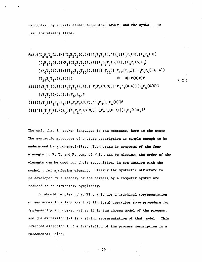
recognized by an established sequential order, and the symbol ; IB
used for missing items.
M215[IoFoTo(i, 2)111 ^ (0,5) ][I2F1T2(3,A)R2][I3Fo(0)'][I4F4(0)]
[I5F5T5(6,13)R2] [I6F6
[ ;F9T9(10. 13) ] [I10F10
[I14FoT14(2,13)]#
tflll2[ ;FoTo(0,l) ] [1^^(
[;F5T5(6/5,5)][;F6;R6]#
mi3[ ;FQ] [IjF^] [I2F2T2(3,2) ] [1^] [ ;F4(0) ]#
The unit that in spoken languages is the sentence, here is the state.
The syntactic structure of a state description is simple enough to be
understood by a nonspecialist. Each state is composed of the four
elements I, F, T, and R, some of which can be missing; the order of the
elements can be used for their recognition, in conjunction with the
symbol ; for a missing element. Clearly the syntactic structure to
be developed by a reader, or the parsing by a computer system are
reduced to an elementery symplicity.
It should be clear that Fig. 7 is not a graphical representation
of sentences in a language that (in turn) describes some procedure for
implementing a process; rather it is the chosen model of the process,
and the expression (2) is a string representation of that model. This
inverted direction in the translation of the process description is a
fundamental point.
- 29 -

For the same reason, Fig. 7 can not be assimilated in the con-
ventional program flow charts. A flow chart is a summary (made a
posteriori) of a command-language description of a procedure. The
elements of this description are typically computer-oriented. Fig.
7 is the actual original model; its elements are typically problem-
oriented. A flow chart is a graphical representation of point C in
Fig. 1; Fig. 7 is a graphical representation of point A in Fig. 1.
2.5.5. FSMs as a programing language
2.5.5.1 General remarks
The use of abstract machines as a language for programing a com-
puter is actually the subject of the entire work undertaken. In this
section we attempt to clarify the relations between our language and
the other known programing languages.
A real comparison between the language for programing a CPL system
and languages for programing conventional computers is not possible,
because the two types of computers are dissimilar. Conventional com-
puters are factory-configurated and the task of the user programing-
language is the management of the Instruction sequences. The CPL system
is configurated by the user and the task of the user programing-language
is the implementation of these configurations. However, because in both
cases the final goal is the same, that of obtaining a certain result
by means of a man-made machine, a discussion on the relations and divers-
ities of the two types of languages should have meaning.
Following a classification of Burkhardt (1965), programing languages
for conventional computers range from
- 30 -

- machine codes
to - assembly languages
- procedural languages
- specification languages
and - declarative languages,
in accordance with the use made of interpretive or translating routines
(compilers). Languages were also proposed that simply state the problems,
without indicating the solution to be used (Cfr. Schlesinger, Sashkin,
1967). This extreme case could not be viewed simply as a programing
language, but should be considered more as a system of solution finding.
It is a characteristic of conventional programing that a process is
described in several forms: in the user language, possibly in an inter-
mediate language of the compiler, in an assembly language, and finally
in the actual binary codes of the computer. In each one of these forms
the process is completely described; each form is obtained from the
previous one by translation.
In programing the CPL system, the solution is completely given by
the user, in the form of an abstract machine that produces the desired
process. The program consists precisely of describing that machine.
We can say that the programing language is not procedural: neither is
it descriptive of the process; it is descriptive of a machine that pro-
duces the process.
This description is made only once. There are not several forms,
each translated from another, as in conventional programing. What is
diversified, instead, is the degree of definition of this description.
First, the user conceives the state diagram for his machine which is a
model of the process . This diagram is composed in terms of the four
- 31 -

building blocks I, F, T, R. Then he, or somebody else, comes back to
that machine and the building blocks are described in complete details.
Finally each resulting piece of the program is written in the proper
form and medium to be fed to the computer.
2.5.5.2. Aspects common with previous languages
APL
Among the programing languages that have been developed, APL
(Iverson, 1962a)is one that suggests some similarity in structure and
goals with the language here described. However, the similarity is
more in the appearance because the two languages are in different frames.
First of all, more than a language for actually programing computers,
APL is a system of concise and powerful notations applicable to a variety
of descriptions and analyses. In particular, it can be used for describ-
ing a process for a computer if suitable compiler, or interpretive
routines, are available (Falkoff, Iverson, 1967). APL per se does not
provide data structuring, input and output, which are crucial points in
computer use. The language described here, instead, is a method for
actually programing a particular type of computer, the CPL system.
In APL, the emphasis is placed on conciseness in describing algorithms;
this is inevitably paid for with a compulsory notation system that is
difficult for the non-expert . Consideration to computers appears only
in the structure as sequences of statements, clearly motivated by the
hope that simple interpretive routines will be able to apply the languages
to the different computers. Because these sequences often are very con-
cise and use arrows for jumps, APL programs have some diagramatical
-32-
appearance, thus resembling structures of FSMs. However, there is
complete absence of the notion of state, which is helpful both for
visualizing the structure of a given process, and for gradually con-
structing a complex program. The viewpoint is fully that of sequence
of statements.
The point is that APL reaches conciseness by means of elegant
notations and not becoming involved in the execution. Iverson himself
(1962a) says that the goal actually is to provide a language with such
a descriptive and analytic power to repay the effort required for its
mastery. He shows (Iverson,196A) the interesting analytical possibility
of the language. In a sense, programing a computer is incidental. The
language described here on the contrary reaches conciseness by
prescribing an execution that is tailored to the model chosen by the
user for visualizing the process. The notation to be used is not of
primary relevance for the method, at least at the present state of
development. We see that the scopes of the two languages are in
different areas.
Iverson talks of common language for hardware, software, and
applications (Iverson, 1962b). But what he means is that APL is very
effective (concise) for describing and analyzing the working of a given
piece of hardware, for describing and manipulating a given piece of
software, and for expressing a given algorithm. All this is very
valuable but is different from the goal expressed in Section 2.1 of
the second Quarterly Report, that of merging the three points of Fig. 1.
We are not interested in describing hardware, software, or algorithms
per se and separately. In our approach, hardware, software and algorithms
- 33 -
are all aspects of the same structure. In this sense not only does
a single language describe them, but it is actually a single description.
For APL, there are three different descriptions for the three aspects.
This different situation is a consequence of the fact that Iverson worked
only on the language, accepting the computers as they are. Here also the
computer is re-examined and changed together with the language.
Decision Tables
For more than ten years (Kavanagh, 1960) decision tables have been
recognized to be a very effective programing method, easily understood
by humans regardless of their background, and to be machine independent.
One item of the FSM description, the function T, has in a sense the
same philosophy of decision tables. Therefore similar advantages can be
expected.
One difference is that conventional decision tables need to be
compiled, in order to be understood by a computer. Here functions T
are directly implemented by the loose hardware of the CPL system.
Another difference is that common decision tables need some interface
with the other general purpose programing languages. Here functions T
are one of the constituents of the language, therefore they are well
integrated in all kinds of programs.
Flowchart ing
Flowcharting started with Goldstine and von Neumann (1947),
"We therefore propose to begin the planning ... by ... the flow
diagram . . .". The first computer programs were flow diagrams with
an accompanying list of codes. Then computers developed, and today
programers do not use flowcharts, except as a secondary, simplified
documentation coming after the program has been written. Conversely,
in programing the GPL system, the first step (Section 2.5.6.1) is the
production of a state diagram, which is the analogous of a flowchart.
The reason for all this is very simple. A graphical representation
of the type of a flowchart is the most effective description of the be-
havior of a processing machine. At the early times programers were
dealing directly with the actual actions of the computer, thus flow-
charts were the most effective program representation. Then programers
freed themselves from the actual working of computers and dealt with
problems more and more in descriptive mathematical terms. In this
situation, flowcharts are completely useless. Now, the FSM is a machine,
and the programer deals directly with it, actually conceiving and con-
structing it; therefore a representation of the type of the flowchart
becomes again the most effective program description. The difference is
that in the early times of computers, the flowchart was describing the
behavior of mechanical or electronic devices that exhibited no resemblance
with the problem as seen by the user; here the state diagram describes
the behavior of an abstract machine that is the concise model of the
problem that the user is dealing with directly. Once this situation is
achieved, it is not difficult to enrich the flowchart with a variety of
features and notations to make it a very expressive, user-oriented repre-
sentation of the problem.
The power of expression of a graphical representation is so obvious
that program theorists often were intrigued with it, aside from its use
for representing the actual work of the computer. It has been proposed
to use flowcharts not only as a notation but even as a programing language
(Burkhardt, 1965); however, it never has been adopted. Caller and Perlis
(1970), in a general analysis of programing languages, raise the question,
- 35 -

"The clarity and precision we have achieved in representing algorithms
by means of flowcharts leads one to ask what it is about flowcharts
that makes them so much clearer than the verbal description". They
recognize that it is not the two-dimensionality of the representation,
because any flowchart can be easily transformed into a linear sequence,
but they do not elaborate further.
In our interpretation, we recognize that the effectiveness of a
graphical representation has a psychological basis. Starting in child-
hood we develop our model and our forecast of the behavior of the out-
side world in terms of an abstract mechanism that we construct in
accordance with sensations, mainly visual. Therefore a graphical repre-
sentation of an abstract mechanism is able to promote very rapidly, and
without effort, a corresponding mechanism in our mind. A sequence of
symbols, conveying the same information, needs first to be memorized
in its entirety (and that implies an effort), then it is analyzed, and
finally the mental mechanism starts to take shape. In the case of a
program, we can say: when an algorithm is represented in a list form,
what we perceive first as a unit is a single command, or declaration,
and it requires a certain amount of work to reconstruct the entire
mechanism from the many commands; when the algorithm is represented in
graphical form, what we perceive first as a unit is the entire mechanism,
and we then need little effort to focus on the single parts in order to
make precise our knowledge of the algorithm.
2.5.5.2. A view of the language for the FSM description
From the programing language viewpoint, our FSM can be summarized
as follows. Four primitive elements are identified:
- 36 -

1. Data transformation function F. This element is obviously always
present if an activity on certain data has to be performed. Only at
particular moments, F can be null because the process in those moments is
in idle state, waiting for some events.
2. New-input-data prescription I. This element will be present at least
in some initial part of the process, if manipulation of given data has to
be accomplished. Even if the process consists only of the creation of
data, certain initial conditions will always have to be given from the
outside.
3. Output prescription R. This element also will aways be present, at
least in some terminal part of the process, if an activity useful for the
outside has to be produced.
4. Next state transition function T. Every time the process is not
described as a single function F, transition functions are necessary.
In fact, even in the case vrtien the process is accomplished with one F
description, the fact that the process should stop at that point can be
viewed as a particular transition.
The FSM is a management of these four primitive elements. This
management is described as a state diagram, where each state is a unit,
a block, defined by a specific ensemble of the four elements F, I, R and
T. In some states, some of the elements can be null.
It should be noted that only new input data need to he described,
and not the current data (as in conventional languages), because the
processing machine keeps in its structure all the data that has been
inputed (by previous prescriptions Is) and not outputed (by previous
prescriptions Rs, or substituted).
- 37 -
It should be noted also that common, quasi-steady Information that
in conventional programing is given in form of declarations, here is
given in terms of code words that preconfigure the processing machine in
such a way that the storage assumes the structure of the data and the
operating network assumes a general structure corresponding to the activity
to be performed.
The six types of data, y, k, I, F, T, and R (see Fig. 2), interact
with each other during processing, but they are handled independently by
the user, a fact that keeps the programing simple.
The language is not procedural for a given computer; it is not
descriptive of the problem in terms of a given set of notations; but it
is descriptive of a particular machine that executes the problem as its
natural response. Because these particular machines are described in
accordance with the abstract mechanisms we conceive in our mind, the
language is claimed to be user oriented. Because these abstract mechanisms
are those we choose for dealing with the problem at hand, the language is
claimed to be problem oriented. It is a fact that the language is the
machine language for a CPL system. This method of modeling processes may
also have potential for programing conventional computers or for an inter-
mediate language like the suggested UNCOL (Strong et al. 1958). Inves-
tigation of such potential is not undertaken here.
The work usually performed by the compiler is here done by the user;
and the user knows a great deal about the data, the purposes, and the
desired choices. Therefore many declarations that are needed in con-
ventional programing, but constitute a somewhat artificial necessity of
the language are not necessary here. One may think that in this way the
- 38 -

user might be overloaded by clerical activities, but this is not the case
because the actual machine follows the image that the user has of the
process.
It should not be overlooked that for humans what is difficult is
what differs from the familiar, not what is complex in analytical terms.
We can walk for hours through mountain paths without falling a single
time; we can talk for hours with a close friend on sophisticated subjects,
feeling the enjoyment rather than tiredness. Such activities are extreme-
ly complex from an analytical viewpoint. Conversely, a simple process
.such as the counting of objects moving on a line, a process that can be
implemented with one photocell, a dozen flipflops and a simple circuit,
is very tiring for humans and it is unlikely that one can do it for more
than one minute without making a mistake.
We present the supposition that conventional programing languages
often fall in the following trap. The user is deprived of the tasks that
he is very capable of and willing to do; these tasks are automated with
very sophisticated software devices; and then, in order to control those
software devices, the user is loaded with activities which are inappropriate
because of being too clerical and extraneous to his interest.
- 39 -

2.5.6 Programing the .CPL sys 1tMii
As said in Section 2.1, programing the CPL system consists of
developing an abstract machine M that produces the wanted process,
and then writing a description m of that machine in a form acceptable
by the CPL system to be used. Clearly we have two phases in the pro-
graming: (1) inventing a machine that can solve our problem, and
(2) determining all the details as necessary for the actual CPL machine.
This division of the programing in two sequential efforts at
different levels is one of the most interesting characteristics of the
approach taken. In Section 2.5.1 it was noted that in conventional
programing the user has no opportunity of starting a program until all
the details are established. Therefore there is no flexibility for
developing different strategies; and when a program is written, it has
often a form so different from the original image of the process in the
user's mind that discussion and changes are extremely difficult. Here
instead, the structure of the program is developed first in a language
suitable to the originator of the process; then the several parts of
that structure are defined in details as needed by the computer, but
still retaining the physiognomy given by the originator. At any time,
the structure and the details can be examined and changed, having an
easy overview of the entire process and an easy access to the several
detailed parts.
To concretize these considerations, the three steos of programing
the CPL 1 processor are described in the following.
1) The process we want to be executed is modelled In the form of
abstract machines of the type described in Section 2.3. In this model-
ing, the user is considering only the characteristics of the process;
there is no concern for machine limitations, because the abstract machines
do not have physical limitations.
The end product of this step is a description of an abstract machine
that performs the desired process. This description is in the form of
a state diagram where each state is composed of the four items I, F, T,
and R. This step is described in Section 2.5.6.1.
2) Operational configurations, possible for the real CPL system are
designed in order to produce the functions F and T delineated in step 1.
This phase of the programing corresponds to the mapping F —> C referred to
in Section 2.4. In this step, the abstract machine outlined in step 1
might be modified in order to meet the characteristics, the size, and
the limitations of the actual CPL system available.
The abstract machine obtained at this point is the accepted model
of our process and in the same time a realizable machine for our CPL
system. This step is described in Section 2.5.6.2.
3) The completed description of the FSMs thus obtained has to be
written in a medium readable by the machine, e.g. a punch card, with
the proper codes. In this form the abstract machine is an actual pro-
gram usable by the available CPL system. This is a clerical step, and
is outlined in section 2.5.6.3.
- 41 -
2.5.6.1 Step 1: Modeling the process in the FSM form
In section 2.5.3 the innate inclination for thinking in terms of
imaginary (abstract) mechanisms was discussed. In this step of pro-
graming, we have to use this innate facility in order to model our pro-
cess in the form of an abstract machine with rigorous connotations,
namely in the form of the FSM represented in Fig. 2, or of a system
of these FSMs circulating in the structure represented in Fig.3 .
The entire process should be framed in the general expressions (1) of
section 2.3. Depending on the transitions between states (well dis-
cernable in the state diagram), expressions (1) act either as a set
of independent functions, or as recursive functions, or any mixture
of the two.
The process is thought out in its inherent phases, parts, or steps,
and correspondingly a set of "states" will be delineated. A state is
a part of the process for which is worth to define a quadruplet [IFTR].
When more than one FSM is involved in the process, each FSM will be
conceived independently in the form of the automaton of Fig.2 , and
then related through the storage P of Fig. 3.
A complex process can be modeled in several ways:
(i) through complexity of the functions F (which corresponds to a
spatial configuration as decribed in step 2),
(ii) through the complexity of the sequential behavior of an FSM (see
state diagram),
(iii) through an array of pages that interact through the auxiliary
storage P of Fig. 3,
- 42 -
(iv) through complexity both of the page array and of the sequential
behavior of each page,
(v) by means of the interaction with specialized devices or auxiliary
storages in the environment.
The ingenuity of a program, its effectiveness and efficiency, are
established here by the way the problem is modeled. In conventional
computers .strategies may be used to exploit to the full, the structure
of a particular computer or of a particular compiler language. In this
case the user is forced to investigate these structures; but usually
they are not of direct interest to him. In programing the CPL system,
strategy has to be used in describing the problem, that is to say on
the structure of the problem itself. In this case we may expect the
user will be interested in expending effort in this direction.
Furthermore, later on he will not feel himself to be a slave of
the computer, because, in preparing the model of his process, he designed
the computer he is going to use.
The best use of the FSM modeling is made when the dynamic aspects
of the process are mechanized in the dynamic behavior of the FSM. A
poor use of the FSM modeling occurs when it is approached simply as a
sequence of commands.
In this stage the structure of a program is established, and there
is room here for the imaginative delineation of the program. Later, in
step 2, skill can be applied to devising single configurations, but that
will affect only the efficiency of single portions of the program. The
remaining step is a simple mechanical manipulation.
- 43 -
2.5.6.2 Step 2: Design of the configurations
Specialized operating configurations have to be designed for the
operating unit of the CPL system available in order for it to perform
the functions F and T delineated in step 1 for each state.
In this step, both the requirements of the problem and the char-
acteristics of the available machine should be considered. If some
function conceived during step 1 cannot be implemented directly, other
alternatives should be examined. A general expedient is to break down
a state into several states, each containing simpler functions,
^he programable networks
It was shown that there is a theoretical and practical basis by
which for any numerical, or logical, function that we can rigorously
describe on certain variables, it is possible to design a network of
logical elements that performs that function with some coding of those
variables.
In our application, this possibility alone is not sufficient; we
need also a general procedure by which a non-professional person can
easily produce these networks from functions expressed in whatsoever
foirm. The basis for this possibility was previously discussed, and lies
in the facility that human beings have for thinking of functions as
abstract machines. In step 1 we were modeling an entire process in the
foTcm of an abstract machine, here we are modeling a function in the
form of an abstract network. The level of complexity is different, but
many points are similar.
For modeling a process, the suggested structure to think of was
automaton of Fig. 2 ; this automaton is a kind of loose sequential
machine. For modeling a function, the suggested structure is an abstract
(symbolic) loose combinational network. The term combinational refers
to the level at which the user looks at the functions: the actual elec-
tronic machine might execute those functions with some sequence of steps,
but this is irrelevant, thus it will be ignored by the user. For some
complex functions, the user may find it difficult to represent the
function in the form of a combinational network; while he would be able
to represent it easily in a sequence of few steps. In accordance to
this fact, the functions F can be represented as a set of different
networks that succeed in a given order on the same data. The processor
CPL 1 has the capability to sequence up to three different configurations
in order to implement the function F in each state.
For different types of functions, a different basic structure of
the network is given to the user: on the basic structure, the user has
to describe the operational character of the elements, the connections
between elements, and all the necessary details in order to obtain the
desired specific function. As an example, in Fig. 8, the basic structure
for the arithmetic functions is reported. The boxes labeled A, B. C and
D represent the internal variables y in the black box of the automaton
of Fig.2 , the boxes a , b , c , d the new input variables x ,
and A', B', C', D' the variables y in the auxiliary page array (ft in1 - S
Fig. 4). Twenty-seven connections are possible between the boxes.
Several operational characters can be attributed to the connections, such
as transfer, sum, subtract, multiply, log , complement, shift, etc.
The user has to devise a combination of connections and operational
characters such that one or more networks will perform the desired data

transformation indicated as function F in that state.
Note that there is no concern for addresses or moving data from
the memory. For the user, the data are always present as variables y
and x in the operating unit. He has only to prepare operating networks;
these networks will automatically be superimposed on the data, in
succession as if transparent sheets such as Fig. 8 were succeeding on
a basic data sheet. The user can then change or move the data, between
cycles of the operating unit, by proper !:new input prescription" I,
and "routing" R.
b
A
\
A1
At\\
I \ \ ^• \ \_\ \^ \
^_
B
t
B1
* ' \ f i-
/ 4 -/ 1.
r I
*-
_ — iv— * H
C
c1
f 4 L
~L~1"_/ f
K' i_^
D
?W 1 A// / / '
/. Y i
D 1 '
Fig. 8 - The basic structure for arithmetic operations
The language for describing the network
After having designed an operational network^ we have to describe
it in some recordable and unambiguous form. We need a language that is
easy for the user and understood by the CPL system. Moreover, for
several practical reasons, it is desirable that this description be
concise.
In information theory it is well known that the information con-
veyed by a string of symbols over an alphabet is highly dependent on
the coding used by the source. In accordance, we might seek for an
optimum coding. But here it is not the case of a communication system
that is designed only once by specialized engineers. Here the encoding
is the language used by non-specialized people for describing the
operational networks that they conceive. Therefore the primary require-
ment is that the encoding be simple for non-specialized users.
To solve this problem a type of coding has been adopted that is
familiar to all of us because it is used in the spoken languages. All
spoken languages use some kind of coding in assembling alphabetic
symbols to form words. That coding is the part of the grammar that
governs the word inflection. Some spoken languages have little coding
and the words can be regarded simply as different combinations of the
alphabetic symbols, only constrained by an acceptable pronounciation.
The meaning of such words, usually short, can be learned only by
memorization. Other languages have sophisticated coding and the meaning
of the words, sometimes amazingly long, can be reconstructed from the

meaning of each group of symbols, following cort.-iln rulcti. Two
are given in Fig. 9. A single German noun of 28 letters (Fig. 9a) means
a place where certificate of paid fee (ticket) for passenger in flight
are given. In Fig. 9b an Italian verb of 12 letters means that you
(several people) would read again if a certain condition occurs. With
such a procedure, an extremely large number of words, with very
specialized meaning, can be constructed without the necessity of memor-
izing (or writing in a dictionary) all of them. The exact meaning of
each word can be reconstructed from the meaning of the building blocks
and the structure of the word.
numberof
symbols
flight guest receipt Belling
i ' i ; iFLUGGASTEGEBUHRSCHEINVERKAUF
(o)
again read would you (people)
I I \ \RILEGGERESTE
(b)
33
29
28
13
Fig. 9 - Examples of aglutinated words

Similar approaches are used here. Taking advantage of the fact
that all the information related to an operational configuration should
be simultaneously present in the operating unit, we ensemble all the
characterization of a configuration in one unit corresponding to an
highly inflected; word of spoken languages. This means that the encoding
of the user language is chosen as encoding function for the control of
the programable network.
One could suspect that in so doing, the coding will be not
optimum for the network. Or if we optimize the coding for the network,
it will be not the most appropriate for the user language. In the design
of the GPL 1 processor, the same coding turned out to be equally
appropriate for the digital design of the programable network and for
the language to be used by non-professional people. In a sense this
is an experimental confirmation of the thesis discussed in section 2.2.
One of the main requirements for a spoken language is the capa-
bility to express an infinite variety of things without requiring
people to learn a corresponding infinite number of independent utterances.
This is the reason for the natural development of agglutination of
different roots and of sintactic structures. Conversely, the shortness
of the utterances is not a strong requirement in spoken languages, on
the contrary a large amount of redundancy is required to overcome the
distortions of the speaker, listener, and environment. Observing
Fig. 9, we see a not large variation of the total number of symbols
(the total number of symbols, plus one space per word, is indicated at
the right-hand side of figure 9). In a language for computers, typically,
we do not need redundancy, given the quiet environment and the re-
liability of the system. In this case also a large reduction in the
number of symbols can be obtained.

In the processor CPL 1, twelve bit words, subdivided in parts, are
used for describing the configurations. A typical organization of the
word, one related to configurations of the type indicated in Fig. 8,
is shown in Fig. 10. The root is related to the operation performed,
the specifier describes the connections, the suffix indicates which
variables are involved, and the prefix is related to some details
peculiar for each type of configuration. All the possible choices
for each part of the word are given by 8-16 entry tables, that are
easily accessible in the dictionary of the processor, or can even be
memorized. It has been attempted to give some memoric pattern to
the assignment of the code, and in fact when a user becomes familiar
to the use of this language, he seldom needs to look into the dictionary.
prefix root specifier suffix
X1 -,X^L /\/ W \ / • \
~T \ \ \Fig. 10 - A word format of the CPL processor
In spoken languages certain words do not have inflections, but are
simply a coded reference to an object or action: similarly, in this
processor, certain specialized configurations that recur frequently
are not constructed in the way previously described, but are simply
called for by a coded number. Using this method, in a particular
application of the processor, very specific configurations can be
prepared in the operating unit, and in the program they are described
by an F treated as a number.
- 50 -

2.5.6.3 Step 3 : Paging the program
The abstract machine described in detail in step 2 can be imple-
mented by the CPL system available; in other words, it is a program for
it. The elements of this program are I, F, T, R's, state labels, and
code words. We can add a name (a number) to the program. The form in
which the program was materialized, during its preparation, is irrelevant;
presumably it will be in the form of a state diagram, or as state
descriptions spread in note sheets.
Now it is necessary to write the program in a medium that can be
read by the CPL system, and all the items should be located follovine
certain rules known by the system. This organization we call pagination
as mentioned in section 2.4.
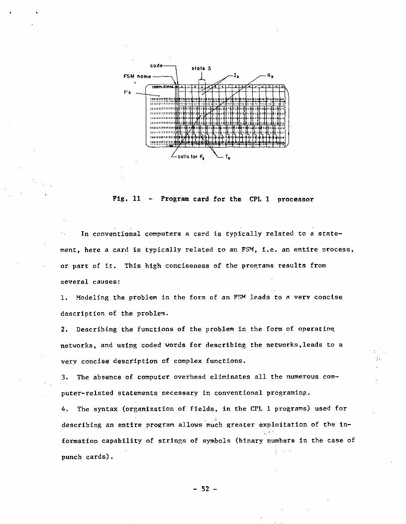
In the CPL 1 processor, the medium is punch cards: the pagination
is given by fixed fields in the card. Fig. 11 shows the fields for the
items constituting an FSM. Usually a same configuration appears several
times in an FSM, therefore it has been found convenient to write them
not in the state descriptions but rather in a field labelled "common
storage". Each state calls for the configurations by means of the number
of the columns where they are written.
A punch card is a binary device, therefore all the information
written in the card will be in the form of binary numbers or coded words
of binary symbols.
- 51 -
code
FSM name
F's
Fig. 11 - Program card for the CPL 1 processor
In conventional computers a card is typically related to a state-
ment, here a card is typically related to an FSM, i.e. an entire process,
or part of it. This high conciseness of the programs results from
several causes:
1. Modeling the problem in the form of an FSM leads to a very concise
description of the problem.
2. Describing the functions of the problem in the form of operating
networks, and using coded words for describing the networks,leads to a
very concise description of complex functions.
3. The absence of computer overhead eliminates all the numerous com-
puter-related statements necessary in conventional programing.
4. The syntax (organization of fields, in the CPL 1 programs) used for
describing an entire program allows much greater exploitation of the in-
formation capability of strings of symbols (binary numbers in the case of
punch cards) .
- 52 -
2.5.7 An example
As an example of programing with the language of Finite
State Machines, a real-time processing for weather radars is described.
This processing (Schaffner, 1972b) aims to measure wind distribution
in the atmosphere from the movement of weather scatters.
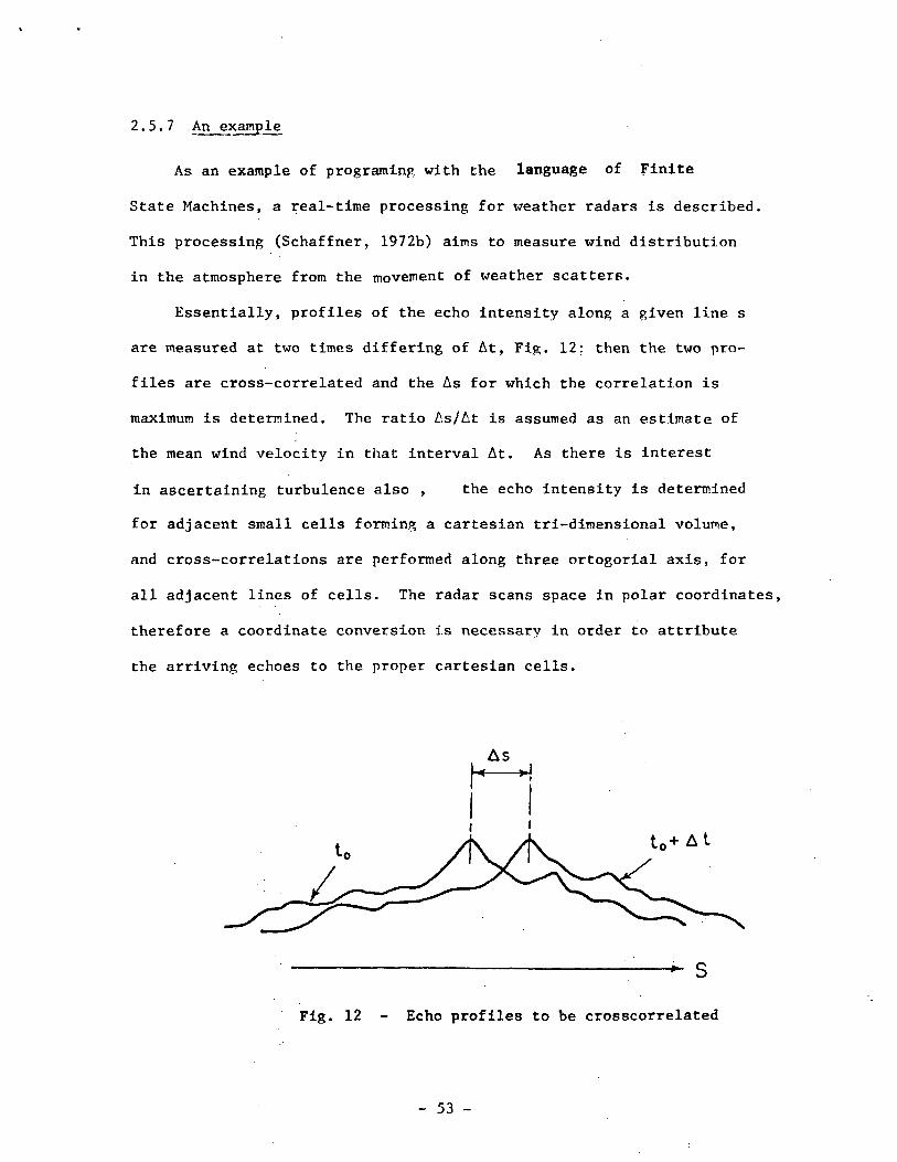
Essentially, profiles of the echo intensity along a given line s
are measured at two times differing of At, Fig. 12: then the two pro-
files are cross-correlated and the As for which the correlation is
maximum is determined. The ratio As/At is assumed as an estimate of
the mean wind velocity in that interval At. As there is interest
in ascertaining turbulence also , the echo intensity is determined
for adjacent small cells forming a cartesian tri-dimensional volume,
and cross-correlations are performed along three ortogorial axis, for
all adjacent lines of cells. The radar scans space in polar coordinates,
therefore a coordinate conversion is necessary in order to attribute
the arriving echoes to the proper cartesian cells.
t«+ At
Fig. 12 - Echo profiles to be crosscorrelated
- 53 -
Undoubtedly such a process would present a very large overhead
for a conventional computer. But if a specific abstract machine is
invented for mechanizing the desired activity, execution of the process
will be straighforward. The following is a first solution for such a
machine .
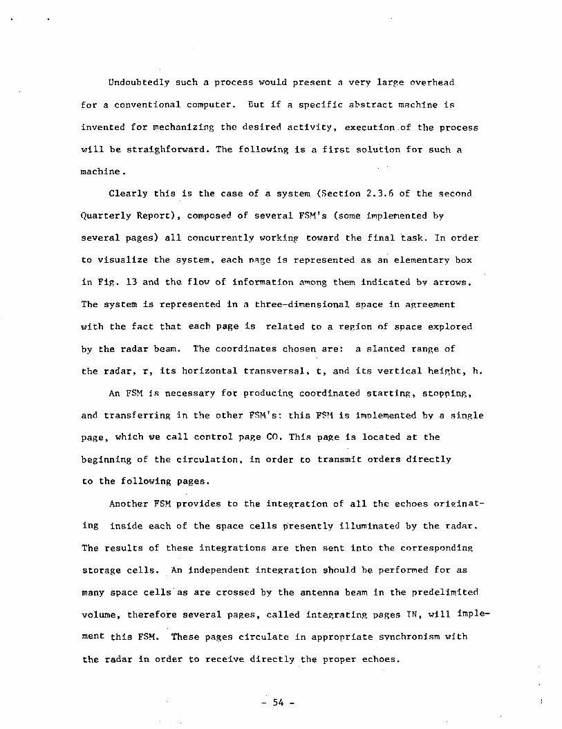
Clearly this is the case of a system (Section 2.3.6 of the second
Quarterly Report), composed of several FSM's (some implemented by
several pages) all concurrently working toward the final task. In order
to visualize the system, each page is represented as an elementary box
in Fig. 13 and the flow of information among them indicated by arrows.
The system is represented in a three-dimensional space in agreement
with the fact that each page is related to a region of space explored
by the radar beam. The coordinates chosen are: a slanted range of
the radar, r, its horizontal transversal, t, and its vertical height, h.
An FSM is necessary for producing coordinated starting, stopping,
and transferring in the other FSM's: this FSM is implemented by a single,
page, which we call control page CO. This page is located at the
beginning of the circulation, in order to transmit orders directly
to the following pages.
Another FSM provides to the integration of all the echoes originat-
ing inside each of the space cells presently illuminated by the radar.
The results of these integrations are then sent into the corresponding
storage cells. An independent integration should be performed for as
many space cells as are crossed by the antenna beam in the predelimited
volume, therefore several pages, called integrating pages TN, will imple-
ment this FSM. These pages circulate in appropriate synchronism with
the radar in order to receive directly the proper echoes.
- 54 -
COV00COa.
0)
QJCO
0)
co
CO4J
CUcoCD
o
f
00-Hu,
- 55 -

Another FSM provides the storage and data manipulation related to
the storage cells. A tri-dimensional array of cells is prescribed,
therefore a corresponding array of pages, called cell pages CE, are
performing this FSM. These pages sometimes will be at rest, simply
capable of receiving data from the IN pages; other times they will
be scanned in each of the r, t, h directions.
Then another FSM is used to collect and manipulate the results
from the cross-correlation in each column and row of the CE oaee arrav.
This FSM will be implemented by pages, called terminal pages TE, in
rt, hr, and ht planes.
Finally, an FSM will provide the accumulation of the output of
each group of terminal pages. This FSM will be implemented by three
pages AC, one for the terminal pages of the rt plane, one for those of
the hr plane, and one for those of the ht plane.
So far the strategy of an ensemble of abstract machines has been
loosely outlined. Now a precise description of these machines has to
be made, following figures 2 and 4. We think of these machines as
abstract entities, formed of states and transitions. We visualize
these machines in the form of state diagrams, representing states bv
circles and transitions by arrows as indicated in Section 2.5.3.2.
A notation system for describing functions F and T has not yet developed
in an organized form, therefore a mixture, of commonly used notations
will be used as needed. Each state (circle) will have up to four fields
for the description of the four primary elements T, F, T, and R. In
the following description of the FSMs, because they are made a posteriori
after having known the solution, there is no sharp distinction between
- 56 _
step 1 and 2 of the programing: in other words, the FSMs are devised
having already in mind a machine of the type of the CPL 1 processor.
FSM IN. This machine starts in state 0, Fig. 14, where the present
coordinates rth, the present video sample, and a 1 are acquired as
three variables y (Fig. 3) labeled A, C and D (Fig. 8). The co-
ordinates rth are the cartesian coordinates (expressed as one word)
of the point presently illuminated by the radar,with a resolution that
determines the size of the cells to be considered. Then the FSM
transfers to state 1 without movement (transition s in Table 2). In
state 1, further samples are accumulated in F> and units in C. After
each accumulation, the present coordinates are compared with those
stored in A: as soon as these coordinates differ, the FSM transfers
to state 2. In state 2, the sample accumulation is divided by the
number of accumulations, range-normalized, and routed to the cell CE
that has coordinates rth equal to those in A. Then the FSM acquires
new coordinates in state 0 and continues as described. With the imple-
mentation given in Fig. 14 only one page IN is necessary for averaging
the video samples and transferring data to the CE pages; the sequence
of IN pages of Fig. 13 refers to a different implementation of this
FSM.
FSM CE. In state 0 of this machine, Fig. 15, the pages are resting in
the memory and are capable only of data acquisition as indicated.
At the end of the first and second radar scans, the pages go to state 1
by a forced transition (e in Table 2) produced by FSM CO. In state 1
the received data are normalized and transferred to a different y.
- 57 -

For the execution of the cross-correlations, each row and column
of pages CE is circulated separately, under the control of FST1 CO and
transferred to state 2 by a forced transition. One of the echo nrofiles
is transferred into C (state 2) and shifted by means of interchange
between adjacent pages (state 3). In state 4 the summation of products
is produced in ft (Fig. 4). State 5 reverses the direction of relative5
movement of the echo profiles, which is produced for k. cell steps
either side. State 6 restores the original allocation of the two pro-
files.
FSM TE. Pages TE are at the end of the rows and columns of pages CE,
therefore , when in state 2 (Fig. 16) they acquire the content of D in
fi and compare it with the content of A ; simultaneously, B is increaseds
by one . Every time D is larger than A, D, and B substitute A and
C respectively (state 3). In this way the As for the maximum of the
cross-correlation (Fig. 12) is acquired. Pages TE go to state 2 (and
connected states) 2k times in synchronism with the production of sums
of products on the part of pages CE. Then the pages go to state A, where
the mean velocity is determined, accumulated into the storage £>. , andS
routed to the output. Because the several cross-correlations are pro-
duced serially, only one page TE would suffice, but here an entire
surface of pages Is maintained in circulation for possible
further processing on the elementary wind components. Also a more
precise determination of As is to be developed with an interpolation
algorithm.
- 58 -

FSM AC. This machine consists of only one state, Fig. 17, where the
accumulation from the TK pages is acquired and routed to the output.
FSM CO. The main tasks of this machine are the control of the pre-
vious FSMs and the production of a magnetic tape record containing the
output data. In state 0, Fig. 18, the data acquisition is started by
means of a forced transition to state 0 for pages IN. In state 1 the
FSM waits for the completion of the radar scanning. In state 2 the
cell pages are forced to state 1 ;and A, used as an index, provides for
the acquisition during two scans. State 3 provides for the starting
of the cross-correlatioh of a particular column or row of the CE pages
by means of the variable coordinates a,6. In state 4 one of the co-
ordinates is increased by 1, and the cross-correlation starts for
another column or row. After m of these, in state 5 the other co-
ordinate is increased by 1, and the series of cross-correlation is
restarted. After mxm cross-correlations, a page AC is activated
(state 6) and the coordinates for selections of pages CE and TE are
rotated, in order to change the direction of the cross-correlations.
Finally, in state 7, a record is produced and all the pages ended.
The entire system is composed of 25 states. If cards of the
type of Fig. 11 are used, the entire program can be described in three
.cards, including a supervisor program for allocating in space the
volume considered and prescribing the schedule of operation.
- 59 -
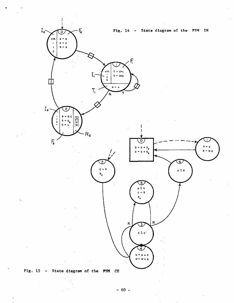
Fig. 1A - State diagram of the FSM IN
Fig. 15 - State diagram of the FSM CE
- 60 -
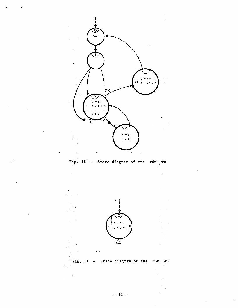
Fig. 16 - State diagram of the FSM TE
Fig. 17 - State diagram of the FSM AC
- 61 -
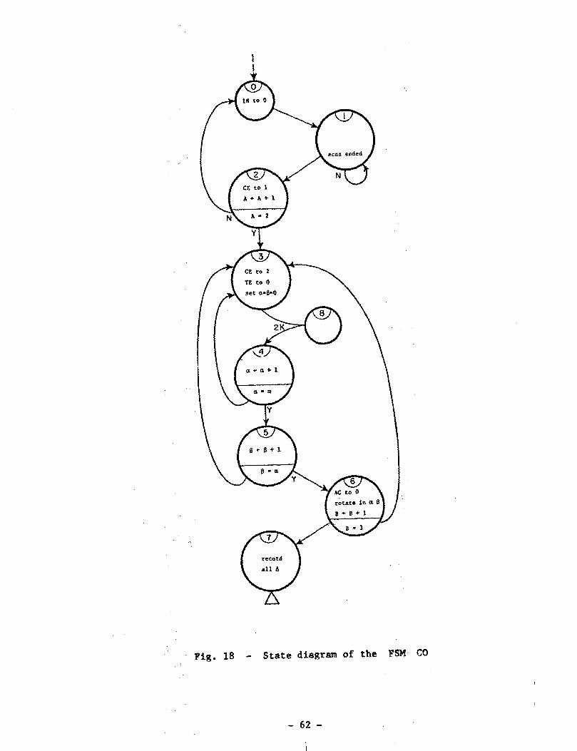
Fig. 18 - State diagram of the FSM CO
- 62 -
3. PLAN FOR THE NEXT QUARTERLY PERIOD
Following the plan outlined in Section 3 of the second Quarterly
Report, the following three remaining tasks will be carried out in the
fourth quarterly period.
1. Specifications for a computer architecture capable .of executing pro-
cesses directly in the form of FSMs in which they are modeled by the
user. An outline of such an architecture has been given in Section 2.4
of the present report. A discussion, and a more detailed description
will be given in accordance with the abstract models described in
Section 2.3, and the programing language discussed in Section 2.5.
2. Comparative evaluation of programs. In the early age of computers,
when people were looking at this new creature with fresh minds, von Neu-
mann conjectured that for complex processes the description of an
automaton that performs the process could be simpler than a symbolic
description of the process itself. lie was envisioning a mathematical
theory of automata that could clarify this issue also. The work re-
mained uncompleted, and the issue did not receive any further
attention.
The results obtained with the restructurable processor analyzed
in the present work revives the interest in the von Neumann conjecture.
In the absence of mathematical means for evaluating the relative con-
venience of the two approaches for describing a process, we can analyze
actual programs written in accordance with the two different approaches.
A set of test programs of different nature, written for a CPL
system, have been selected. Programs for the same processes, but
- 63 -
written in conventional programing languages, are under preparation.
The comparative analysis of these two sets of programs should provide
information on the relative practical advantages and disadvantage of
the two approaches.
3. Compilation of the Final Report. The entire analysis of the system,
which has been gradually exposed in the Quarterly Reports, will be
compiled and edited in a consistent form, including the results of the
last quarterly period.
- 64 -

REFERENCES
Blumenthal, A. L. (1970): "Language and Psychology, Historical Aspectsof Psycholinguistics", John Wiley & Sons, Inc.
Burkhardt, W. H. (1965): "Universal Programming Languages and Processors,a brief survey and new concepts" , AFIPS , Fall JCC , vol. 27,part. 1, p. 1-21.
Chomsky, N. (1957): "Syntactic Structures", The Hague: Mouton & Co.
Chomsky, N. (1965): "Aspects of the Theory of Syntax", The MIT Press,Cambridge, Mass.
Falkoff, A. D. and K. E. Iverson (1967): "APL 360 Terminal System",Pjroc. Symp. Interactive System, Academic Press.
Flavell, J. H. (1963): ''The Developmental^ Psychology of Joan Piaget",Van Nostrand Co., Inc., Princeton, N.J.
Caller, B. A. and A. J. Perlis (1970): "A View of Programming Languages",Addison-Wesley, Reading, Mass.
Goldstine, .H..,H_. and J. von Neumann (1947): "Planning and CodingProblems for. an Electronic Computing Instrument-", reprintedin A. H. Taub, "John von Neumann Collected Works", Vol. V,pp. 80-235, Pergaraon Press, 1961 .
IEEE (1972): International Convention, N.Y., Panel Discussion onproblem-oriented, user-oriented languages.
Iverson, K. E. (1962a): "A Programming Language", John Wiley and Sons,N.Y.
Iverson, K. E. (1962b): "A Common Language for Hardware, Software, andApplications", Proc. Fall JCC. v. 22, p. 121.
Iverson, K. E. (1964): "Formalism in Programming Languages", Com^ACM,v.7, n.2, pp80-88.
Kavanagh, T. F. (1960): "Tabsol, a Fundamental Concept for System-OrientedLanguages", Proc^ J1960 Eastern JCC, pp 117-136.
Kutti, A. K. (1928): i:0n a Graphical Representation of the OperatingRegime of Circuits", in E. F. Moore (Editor), "Sequential Machines,Selected Papers", Addison-Wesley Publishing Co., Inc., 1964, trans-lated from "Trudy Leningrad_skpi_ Eksperimental noi Elektro-tekhnicheskoi Laboratorii, Vol. 8 (1928)".
- 65 -

Handler, J. M. and G. Handler (1964): "Thinking, from Association toGestalt'', John Wiley & Sons, Inc.
McCulloch, W. S. and W. Pitts (1943): "A Logical Calculus of the IdeasImmanent in Nervous Activity", Bull. Math. Riophys. , 5, pp 115-133.
Miller, G. A. (1964): "Mathernatics and Psychology", John Wiley & Sons,Inc.
Minsky, M. L. (1967): "Computation; Finite and Infinite Machines".Prentice-Hall, Inc., Englewood Cliffs, New Jersey.
Piaget, J. (1950): "The Psychology of Intelligence" , Routled & KeganPaul Ltd., London.
Sammet, J. E. (1969): "Programming Languages; History and Fundamentals",Prentice-Hall, Inc., New Jersey.
Schaffner, M. R. (1971): "A Computer Modeled after an Automaton",Proc. Symp. Computers and Automata, MRI Symp. Vol. XXI, PolytechnicInstitute of Brooklyn, Brooklyn, New York, pp 635-650.
Schlesinger, S. and L. Saskin (1967): "POSE, A Language for PosingProblems to a .Computer", Com. ACM, v. 10, n.5, p. 279-285.
Strong, J., Wegstein, J., Tritter, A., Olsstin, J., Mock, 0., andSteel, T. (1958): "The Problem of Programming Communication withChanging Machines, A Proposed Solution", Com. ACM, v.l, n.8 and 9.
von Neumann, J. (1948): "'The General and Logical Theory of Automata",Hixon Symposium, Pasadena, Cal., reprinted in A. H. Taub, "Johnvon Neumann Collected Works", Vol. V, pp 288-328, Pergamon Press,1961."
von Neumann, J. (1953): ''JJlfLJ?oIllEu^e-L_?l _ !Le--JjJilLl'» Yale Univ. Press,New Haven, Conn.
von Neumann, J. (1966): "Theory of Self-Reproducing Automata1' , Un. of111. Press, Urbana, 111.
Turing, A. M. (1936): "On Computable Numbers, with an Application tothe Entscheidungsproblem", Proc. London Math. Soc. , Ser. 2-42,pp 230-265.
Whorf, B. L. (1956): "Language Thought and Reality", The MIT Press,Cambridge, Mass.
- 66 -