study of intelligent impedance control using a fuzzy
TRANSCRIPT

Study of Intelligent Impedance Control Using a Fuzzy Neural Network Ryota Koga*1, Yoshishige Sato
Dept. of Control and Information Engineering, Tsuruoka National College of Technology Tsuruoka City, Yamagata Prefecture 997-8511 E-mail: [email protected]
Abstract
This paper presents a study of adaptive force control that takes into account object
characteristics using a fuzzy neural network. This study applies fuzzy theory to position
control and force control, similar to those actually implemented by industrial robots, to
enable automatic establishment of optimum parameters for different environments and
autonomous and flexible motion.
Keywords: adaptive force control, fuzzy neural network, intelligent impedance control
1. INTRODUCTION
In recent years, the industrial world has been anticipating the arrival of robots capable of coping with
differences in environment and object characteristics. These robots would be capable of what is called
humanoid motion. This study of Intelligent Impedance Control using a Fuzzy Neural Network applies
fuzzy theory to position control and force control, similar to those actually implemented by industrial
robots, to enable automatic establishment of optimum parameters for different environments and
autonomous and flexible motion. After the motion of a constructed control model was verified through
simulation and experiments at the uniaxial stage, it was then installed into an arm robot, the ultimate
target of this research, for a final confirmation of motion.
2. INTELLIGENT IMPEDANCE CONTROL
In this research, a neural network[1,3,6,7,8] and fuzzy neural network are used in the system, as shown
in the block diagram, Fig. 1.
There are control systems for position and force, each composed of a two-degree-of-freedom[2]
structure combining feedback and feedforward[5,10,11,12]. In the FF-NN (neural network block), even
greater linear control is achieved by giving the inverse of Plant characteristics. Also, the FB-FN (fuzzy
neural network block) is utilized to cancel disturbances caused by unsteadiness and friction arising from
motion that the FF-NN cannot fully absorb. These are achieved by fine-tuning the fuzzy parameters to
carry out ill-defined controls and through the learning capabilities of the neural network[4,9].
*1 機械電気システム工学専攻
平成23年度修了生 (東北エプソン㈱)

Fig.1. Block diagram of control
The structures are illustrated in Fig.2 and Fig.3.
This shows the fuzzy neural network is employed the neural network theory.
Fig.2. Neural network structure
The neural network has a 3-layer structure with an input layer, a hidden layer, and an output layer. It uses
displacement, velocity, and acceleration for position input, and force, viscosity, and rigidity for force
input.
Position command
Select command
Neural Network
compensator
Kh FN PD
FN PI
s
s1/s
ss2
Neural Networkcompensator
FN PD
FN PI
s
s1/s
ss2
Force command
α
Robot
+
ー
+
ー+
+
+
+
+
+
+
+q
F
Fuzzy Neural Networkcompensator
Fuzzy Neural Networkcompensator
r
dr dt
dr dt
2
Inout
Layer
Hidden
Layer
Output
LayerWij
Wi2
Fig. 5 Feedfoward neural network compensator
uNN =Σ WiΨ(xi)i=1
m2
uNN
鶴岡工業高等専門学校研究紀要 第48号
- 48 -

Fig.3. Fuzzy neural network structure
It is split into an antecedent and consequent, with the antecedent applying membership function to
determine nonlinear function. The consequent weights the control using fuzzy rules.
)()()()( dfddhdax FFKSESFxxSKKxxBxM (1)
X: position, Xd: position command, Mx: inertia matrix, Ba: damper matrix,
Kd: virtual spring matrix, F: force response, Fd: force command, S: switching matrix
diag(S1,- - -,S6), Kf: force gain, E: unit matrix
S, M, B, K are 6×6 matrices(X,Y,Z,XM,YM,ZM)
Defined as in Equation (2) the impedance as a secondary vibration system are in terms of the
displacement force.
dax KsBsM 2
1 (2)
① ② ③
①Mx: Material rigidity (fixed)
②Ba: Virtual viscosity Parameters set by NN learning
③Kd: Virtual rigidity Parameters set by NN learning
Adjusting parameter Kh allows smooth, continuous switching of complete force control and position
control through compliance control.
This method makes continuous setting of 3 modes possible by adjusting just 1 parameter.
A
A
A
A
A
A
1
11
W
W
W
Πμ
μ^
^1
2
^
e
11
21
31
12
22
32
1
2
p
ev 9
A
A
A
A
A
A
1
11
W
W
W
Πμ
μ^
^1
2
^
e
11
21
31
12
22
32
1
2
p
ev
u FN-PD
uFN-I
9
S1
S
+
+
u FN
ep
(4) Architecture of the fuzzy-neural network
(A) (B) (C) (D)
古賀・佐藤:Study of Intelligent Impedance Control Using a Fuzzy Neural Network
- 49 -

Kh=0(α=1) force control
)()(1)()( dfdax FFKSESFxxBxM (3)
Kh=Khmax (α=0) position control
SFxxSKxxBxM dddax )(1)()( ・ (4)
0<Kh< Khmax (1>α>0) compliance control
)()(
)()()(
df
ddhddx
FFKSESF
xxSKKxxBxM
・
・
(5)
Not directly set, α coefficient is calculated by substituting the Kh to equation (6) the following.
ch
c
KK
K
(6)
Kc: Constant 0.1 , Kh: Virtual spring constant
α: Configuration parameter control mode
The control model for this research was constructed with 2 kinds of input, position command and force
command. Each was integrated after fuzzifying. Fig.4 shows the actual model diagram built using
MATLAB Simulink.
Fig.4 Fuzzy model diagram
鶴岡工業高等専門学校研究紀要 第48号
- 50 -
3 Experiment
3.1 System configuration
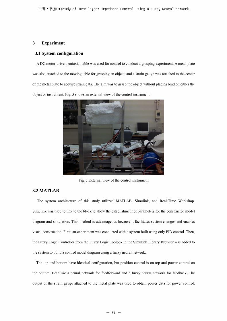
A DC motor-driven, uniaxial table was used for control to conduct a grasping experiment. A metal plate
was also attached to the moving table for grasping an object, and a strain gauge was attached to the center
of the metal plate to acquire strain data. The aim was to grasp the object without placing load on either the
object or instrument. Fig. 5 shows an external view of the control instrument.
Fig. 5 External view of the control instrument
3.2 MATLAB
The system architecture of this study utilized MATLAB, Simulink, and Real-Time Workshop.
Simulink was used to link to the block to allow the establishment of parameters for the constructed model
diagram and simulation. This method is advantageous because it facilitates system changes and enables
visual construction. First, an experiment was conducted with a system built using only PID control. Then,
the Fuzzy Logic Controller from the Fuzzy Logic Toolbox in the Simulink Library Browser was added to
the system to build a control model diagram using a fuzzy neural network.
The top and bottom have identical configuration, but position control is on top and power control on
the bottom. Both use a neural network for feedforward and a fuzzy neural network for feedback. The
output of the strain gauge attached to the metal plate was used to obtain power data for power control.
古賀・佐藤:Study of Intelligent Impedance Control Using a Fuzzy Neural Network
- 51 -
The model diagram built with Simulink was converted to C source with Real-Time Workshop and entered
into an embedded computer to operate the instrument.
3.3 System flow
Numbers ①–⑥ illustrate the system flow.
① C source converted with Real-Time Workshop is entered into an embedded computer.
② The motor is driven according to simulation.
③ Strain gauge voltage is produced at the moment an object is grasped.
④ Voltage amplified by an amp is converted to a digital value by an A/D converter.
⑤ Strain gauge output is received as power data, and power control starts.
⑥ Voltage applied to the motor and strain gauge output are displayed on the computer in real time.
VC Designer software was used for the computer display (⑥) to create a system showing a real-time
graph display of voltage applied to the motor and strain gauge output.
3.4 Experiment method
As previously noted, this study aimed to construct a system capable of flexibly handling differences in
object rigidity. That is, even when the characteristics of a component on a manufacturing line suddenly
change, the conventionally required resetting of parameters is omitted, object-appropriate autonomous
adjustment of pressure is achieved, and motion can be executed without load.
Since a variety of instances had to be anticipated in this grasping experiment, objects with totally
different properties and rigidity were used. Observations and indications for improvement were derived
from outcome disparities between a conventional PID control system and an adaptive force control
system using a fuzzy neural network. Fig. 6 shows the objects used in the experiment.
鶴岡工業高等専門学校研究紀要 第48号
- 52 -

Styrofoam Building block Sponge
Coil Chalk Stuffed animal
Fig. 6 Objects used in the experiment
(1) Experiment using PID control
First, a grasping experiment was conducted with a model diagram using PID control. This system also
had a built-in neural network for feedforward because, ultimately, this study attempted to prove the
outcomes of a fuzzy neural network. Also, PID block parameters for control were set at parameters more
appropriate than experimental values to observe output waveform and show even greater efficient
convergence. The established parameters were P=1, I=0, D=0.1.
(2) Experiment using a fuzzy neural network
The model diagram for the PID block constructed in the previous step was changed to a fuzzy neural
network, at which time displacement and velocity were input, so the input signal and first-order
differentiation signal were bundled and linked to the block. The fuzzy block treated this displacement,
velocity, and output during PID control as an instruction signal, and learned from these 3 pieces of data.
In addition, though not stated in item (1), a neural network was needed. This bundled 4 pieces of
data—displacement, velocity, acceleration, and, like the fussy neural network, PID control output—into a
古賀・佐藤:Study of Intelligent Impedance Control Using a Fuzzy Neural Network
- 53 -

single-file instruction signal as an array, from which it learned.
(3) Learning
(a) Neural network learning
Data on displacement, velocity, acceleration, and instruction signal were collected and input into the
“NN TRAIN1.m” file, and learning was completed through execution. At this time, the various signals
required for learning used a block data storage function called scope that was utilized when waveform
was observed during simulation. Since the saved data became quite large, it was culled to adjust data
quantity. Data was stored in the MATLAB workspace.
The data stored in the workspace was input into “NN TRAIN1.m.” The 3 pieces of data, displacement,
velocity, and acceleration, were assigned to the P array in the M file, and the instruction signal was
assigned to the T array. Fig. 7 shows an actual screenshot.
Fig. 7 Screenshot of “NN TRAIN.m”
(b) Fuzzy neural network learning
Like the neural network, the 3 pieces of data—displacement, velocity, and instruction signal—were
saved as a single data array. The FIS Editor screen for the fuzzy block that was to be learned was
opened, input was doubled, and the Gaussian function was applied to the function. In this way,
input/output were set and rules were established in the FIS Editor. Next, Anfis was selected from the
edit tab. Fuzzy block learning took place in Anfis. Learning was executed by loading the created file.
Learning frequency was set with the number of Epochs in Train FIS.
4. Experiment results
4.1 Results from the experiment using PID control
鶴岡工業高等専門学校研究紀要 第48号
- 54 -

A grasping experiment was conducted using the previously noted 6 objects. Here, Fig. 8 shows
representative results from the building block, Styrofoam, and stuffed animal. Even using PID control,
it proved possible to grasp the objects without overloading them.
Fig. 8 Experiment results for the building block, Styrofoam, and stuffed animal
Building block Styrofoam
Stuffed animal
Vol
tage
(V
)
Time (sec) V
olta
ge (
V)
Time (sec)
Vol
tage
(V
)
Time (sec)
Vol
tage
(V
)
Time (sec)
Vol
tage
(V
)
Time (sec)
Vol
tage
(V
)
Time (sec)
Position Position
Force Force
Position
Force
古賀・佐藤:Study of Intelligent Impedance Control Using a Fuzzy Neural Network
- 55 -

Each of the upper graphs show voltage applied to the motor, or changes to the trajectory of the voltage
applied to the motor, while the lower graphs show strain gauge output when the objects were grasped.
The take away from the 3 experiment results is the fact that output from the strain gauge abruptly rose
from the moment an object was grasped. This shows that load was placed on the objects, and that it took
time for the appropriate pressure to be applied. Therefore, the motor also tried to compensate for the
too-tight grasp by easing it through counter-rotation, but in the end, it required time to converge power
control. Ideally, the system would instantaneously apply appropriate pressure to grasp an object so that
convergence efficiently occurs. This was the goal of the experiment conducted next that used adaptive
force control through a fuzzy neural network. Table 1 shows a comparison of experiment results for the 6
objects.
Table1Experimentresults
The convergence time shown as “0” in the table indicates the time it took for voltage applied to the
motor to reach “0,” which can also be expressed as the time it took to switch to power control. The table
shows that, when grasping soft objects like the stuffed animal, necessary pressure is not applied and
Convergence time to 0
Time to strain stability
Max. strain voltage
Sponge
Stuffed animal
36sec.
approx. 2.6V 11sec. 36sec.
approx. 2.3V 12sec.
over 60sec. 15sec.
approx. 2.7V 9sec. 38sec.
24sec. 13sec. approx. 2.1V
45sec. 25sec. approx. 1.5V
approx. 0.9V
Building block
Styrofoam
Coil
Chalk
Table 1 Experiment results
鶴岡工業高等専門学校研究紀要 第48号
- 56 -

convergence can never be accomplished, as is also apparent from the experiment results graph.
Convergence also took time for other soft objects like the sponge. Time to strain stability indicates the
time it takes for the instrument to stabilize and necessary pressure to be applied. As expected, highly rigid
objects took a certain amount of time due to abrupt output. It also took time for mildly rigid objects
because, although strain gauge output was gained as the metal plate bent when the object was grasped,
there was no abrupt output with the mildly rigid object, so acquiring enough output unavoidably took
time. The maximum strain gauge output from when the object was grasped was also compiled. On
average, 1.2V of output was sufficient to steadily grasp an object. However, as anticipated, highly rigid
objects had over twice the output. Eliminating this abrupt output is the biggest issue.
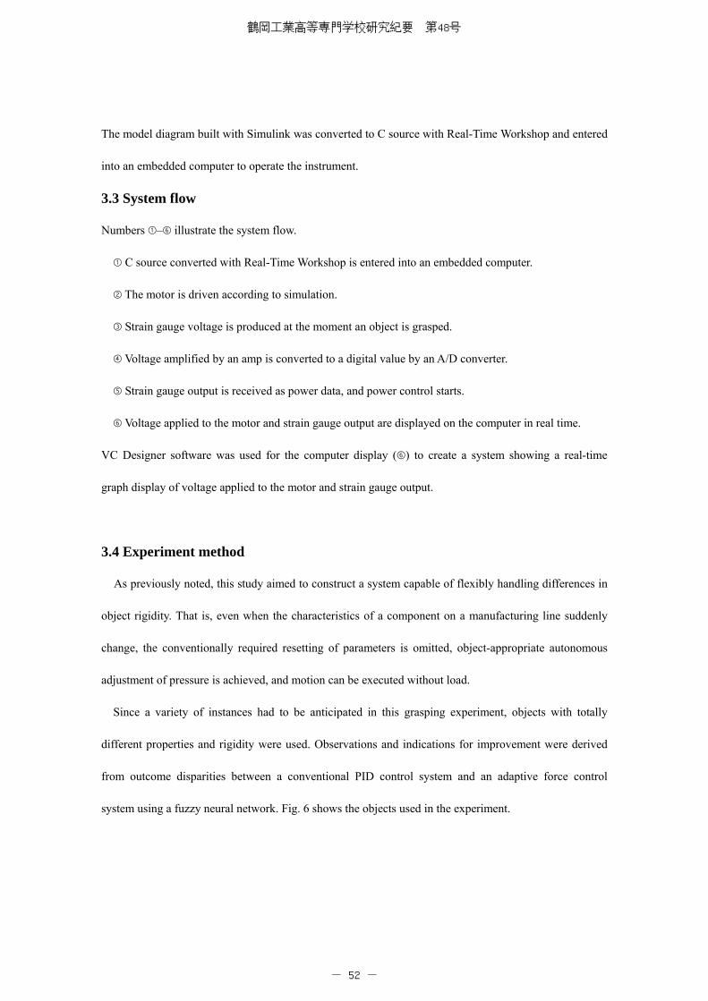
4.2 Results from the experiment using intelligent impedance
In this study, the output from the building block PID was learned as an instruction signal. A
comparison was made with the previous experiment between the building block and Styrofoam, which
has relatively similar rigidity. Fig 9 shows the two experiment results.
Building block (after learning)
Vol
tage
(V
)
Time (sec)
Vol
tage
(V
)
Time (sec)
Position Force
古賀・佐藤:Study of Intelligent Impedance Control Using a Fuzzy Neural Network
- 57 -
Fig. 9 Experiment results after learning
Compared to the previous experiment outcomes, the abrupt output of the strain gauge seen during PID
control and the accompanying applied voltage overshoot were successfully eliminated, enabling the
efficient application of optimum pressure needed to grasp the objects. A system was successfully
constructed that did not place load on either the object or instrument. A comparison of experiment results
was conducted using time to convergence.
Building Block:
Convergence time to “0”: 36sec. (before learning) → 12sec. (after learning)
Time to strain gauge output stability: 11sec. (before learning) → 3sec. (after learning)
These results show that each convergence time improved by approximately a third.
5. Discussion
A comparison of the two experiments reveals that learning through a fuzzy neural network is extremely
effective for intelligent impedance control. It can curb abrupt output from the strain gauge and allows
operation that does not place load on either object or instrument. In addition, since the PID parameters
Styrofoam (after learning)
Vol
tage(
V)
Time (sec)
Vol
tage
(V)
Time (sec)
Position
Force
鶴岡工業高等専門学校研究紀要 第48号
- 58 -

used in the instruction signal were provided by the author based on appropriate experiment values and it
is possible that a slight deviation from the ideal trajectory occurred, establishing even more appropriate
PID parameters for the instruction signal will enable the construction of a system that operates even more
efficiently.
This study conducted learning by using a building block, but utilizing the system to conduct a grasping
experiment with a stuffed animal revealed that a wide range of object rigidity is covered since identical
improvements were seen with other objects. However, because the strain gauge currently utilized for
power input performs more poorly than electrostatic power sensors of the kind that are actually installed
on an arm, the grasping experiment could not be conducted at high velocity. Thus, there is a need to
conduct an experiment with the table moving at high speed and confirm the difference in accompanying
outcomes.
6. Conclusion
The implementation experiment confirmed that efficient impedance control is possible through
learning that uses a fuzzy neural network. In addition, because objects such as chalk that are easily broken
could also be grasped when diagonal force was applied without placing load on the object, a system was
successfully built that made possible the original goal of “human-like action” that uses appropriate force.
Therefore, this study reaffirmed that efficiently applying the necessary pressure to objects with any kind
of rigidity requires the construction of a system that automatically adjusts gain using a learning function.
These results illustrate the necessity of a flexible system that uses appropriate force not only in the
industrial world where robotic arms and various precision equipment are utilized, but also in medical
fields related to nursing where care robots provide personal care for the elderly by grasping a variety of
objects and making direct bodily contact. This kind of robust, intelligent impedance control system is now
being eagerly awaited, and it is thought that its use will spread to many other fields aside from those
noted above.
古賀・佐藤:Study of Intelligent Impedance Control Using a Fuzzy Neural Network
- 59 -

References
[1] T. Yabuta, T. Yamada: “Force Control for Robot Manipulators using Neural networks,” JRSJ, Vol. 9
No. 2, pp. 224–231 (1991).
[2] A. Shimokawabe, et al.: “Control Performance of Two-stage Positioning System with Intelligent
Control Methods,” JSME, Vol. 66 No. 648 (2000)
[3] Noguchi, Yoshida, et al.: “The Control of the PUM Type Robot with a neural network and the
adaptive control,” No.15 JRSJ.
[4] K, Onishi: “Robust Motion Control by Disturbance Observer,” JRSJ, Vol. 11 No. 4 pp. 486–493
(1993)
[5] Umeno, Hori: “Constitution of Two Free Angles Robust Servo System and Application to the Motion
Control of Manipulator,” JSEE, 110–11 1163–1170 (1990).
[6] S. N. Huang, K. Ktan, and T. H. Lee: “Adaptive Friction Compensation using Neural Network
Approximations,” IEEE TRANNCIONS ONSYSTEM MAN, AND CYBERNETICS-PART, Vol. 30
No. 4 (2000–11).
[7] M. Isogai, F. Arai, T. Fukuda: “Study about Vibration Control using Modeling of Flexible
Multi-Linking System and Neural Network,” JSME, 638 (1999–10).
[8] Kobayashi, Murata, Morisawa: “Fundamental Study about Adaptation to Oil Pressure Servo
Mechanism of Neural Network,” JSME, 638 (1990–10).
[9] R. Yoshino, H. Takahashi: “Vibration Control of Low Rigidity Legged Locomotion Robot by Filter
Inclusion LQ Servo,” JRSJ, Vol. 18 No.1, pp. 110–119 (2000).
[10] Y._Sato: Robust Fuzzy Neural Network Based Control System for Mechatronic Servo Systems
with High Nonlinearity,_TJSME, 69C-687, pp. 2929-2936(2003)
[11] Y._Sato: Robust Fuzzy Neural Network Based Control System for Mechatronic Servo Systems with
High Nonlinearity,(2 nd Report, Analysis on the Stability and Robustness or System) , TJSME
70C-700, pp. 78-85 (2004)
[12] Y. Sato: A Design of Fuzzy Neural Network Based Gain Scheduling Controllers, IEEJ Trans. EIS,
Vol.127, No.8, pp.1221-1227 (2007)
鶴岡工業高等専門学校研究紀要 第48号
- 60 -