study for the compensation grouting. the case of the
TRANSCRIPT

1
Study for the Compensation Grouting: The Case of the Underground Railway of Florence
P. Cucino, S. Fuoco, D. Maniezzo
SWS Engineering S.p.A., Trento, Italy 1. Introduction A new underground link is under construction in Florence and connects the existent Florence-Rome railway track to the new high speed railway line from Florence to Bologna. This connection will be almost totally underground in urban areas, and it has an overall length of approximately 6 km (Fig.1) with a cover thickness from 5 m to about 26 m. The new railway station is going to be located along the link track almost in the middle of the path. The settlements due to the tunnel excavation will be constantly monitored: special compensation techniques have been studied to avoid any damage to the buildings in the areas surrounding the tunnel, with particular regard to historical buildings. Nowadays the choice of the best injection technique, appropriate mixture quantity, order and number of grouting valves, is principally demanded to operators experience and know-how which results hard to transfer from one to another. The numerical study (performed by means of a 3D design software) summarized in this paper shows the effects which some key features have on compensation procedures. This study reproduced excavation advance simulating the EPB shield, surface settlement and ground reaction to compensation grouting. The results obtained from the numeric model represent a valid reference to esteem, for the simulated boundary condition, the influence of grouting on superficial subsidence field. Furthermore, the study defines an analytic procedure to design compensation grouting with regard to mixture quantity and quality, procedures and sequences to be applied for execution and defines a meaningful performance parameter to be used for design. 2. Compensation grouting Compensation grouting is one of the existent injection techniques. The technique consists in grouting a controlled amount of mixture at a controlled pressure. The technique allows consistently reducing or completely avoiding settlements induced by excavation on superstructures. Grouting is performed by means of valved-pipes located at a suitable distance from superstructure and tunnel face. Differently from traditional methods, compensation grouting can be regarded as an active technique. In case of an unexpected ground settlement, the method can be applied and modified in real time to fit settlement evolution. 3. Compensation grouting modeling: Florence underground rail link
Compensation grouting has been in-depth studied to determine the key parameters linking practical procedures and ground reaction in order to punctually define design compensation operations for the different cases.

2
In particular, the key features studied were the influence of ground characteristic parameters and the grouting technique, with special regard to the volume to be grouted and to the number of valves to be simultaneously activated. The results obtained have been compared to the theoretical results foreseen in design stage.
Fig. 1 Florence railway link plan
Fig. 2: Bld. 166 – compensation grouting valved-pipes layout – vertical section
Ground reaction to excavation advance has been studied gradually passing from the evaluation of ground settlement in plane condition, to the simulation of the same phenomenon in tri-dimensional conditions, and eventually studying compensation grouting effects. The study example is a building named “Building 166” (Fig. 2), and grouting is going to be executed from a well realized on purpose next to the building. Ground composition is mostly constituted of sand within a silt-clay matrix. Soil characteristic parameters, function of the constitutive model adopted, are listed in Table 1. Constitutive models studied were: Linear Elastic (E); Elastic-Perfectly Plastic (MC=Mohr Coulomb); Non-Linear Elasto-Plastic (MCM modified Mohr Coulomb)
Benchmark γγγγ νννν c’ φφφφ’ E E(50) Eed Eu/r ψψψψ m KNC
Units (kN/m3) (-) (kN/m2) (°) (MPa) (MPa) (MPa) (MPa) (°) (-) (-)
Elastic Model 20 0.2 30
Elastic-Perfectly plastic Model 20 0.2 5 27 30 27
Non linear Elasto-Plastic Model 20 0.2 5 27 10 10 30 27 0.5 1
Table 1. Characteristic material parameters used for analysis.
Where: γ is saturated soil weight, ν is Poisson coefficient, c’ is effective cohesion, φi’ is the angle of internal friction, E is Young modulus, E(50) is modulus of deformation at 50% of triaxial load capacity, Eed is Young Modulus derived from edometric test at a reference pressure, Eu/r is Young
Modulus in loading-unloading path, ψ is angle of dilatation, m describes the non-linear behavior during loading-unloading and KNC stands for the soil overconsolidation level. 3.1 Subsidence study – Analytical and numerical evaluation
Analytic evaluation has been performed using the Peck formula [16]:
( )
⋅
−
⋅⋅⋅
=2
2
2
2313.0
i
y
p
v ei
DVyS
Where Sv(y) is vertical subsidence, function of the distance, y, from tunnel axis (along the orthogonal direction to the axis); Vp = loss volume = Vsub/Vexcavation = volume derived from the subsidence curve / excavation volume; D = excavation diameter; k = numeric coefficient function of soil type; i = K*z0 = distance from inflexion point of subsidence curve and tunnel axis, and z0 = tunnel axis depth.
3
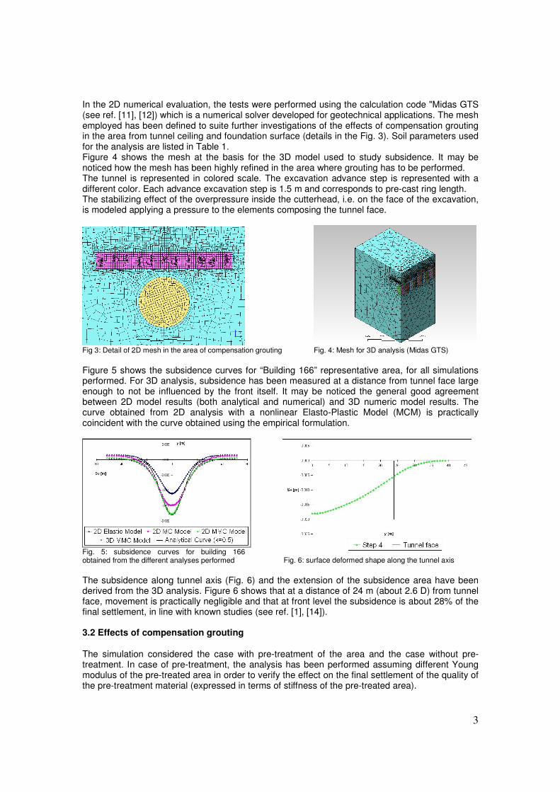
In the 2D numerical evaluation, the tests were performed using the calculation code "Midas GTS (see ref. [11], [12]) which is a numerical solver developed for geotechnical applications. The mesh employed has been defined to suite further investigations of the effects of compensation grouting in the area from tunnel ceiling and foundation surface (details in the Fig. 3). Soil parameters used for the analysis are listed in Table 1. Figure 4 shows the mesh at the basis for the 3D model used to study subsidence. It may be noticed how the mesh has been highly refined in the area where grouting has to be performed. The tunnel is represented in colored scale. The excavation advance step is represented with a different color. Each advance excavation step is 1.5 m and corresponds to pre-cast ring length. The stabilizing effect of the overpressure inside the cutterhead, i.e. on the face of the excavation, is modeled applying a pressure to the elements composing the tunnel face.
Fig 3: Detail of 2D mesh in the area of compensation grouting
Fig. 4: Mesh for 3D analysis (Midas GTS)
Figure 5 shows the subsidence curves for “Building 166” representative area, for all simulations performed. For 3D analysis, subsidence has been measured at a distance from tunnel face large enough to not be influenced by the front itself. It may be noticed the general good agreement between 2D model results (both analytical and numerical) and 3D numeric model results. The curve obtained from 2D analysis with a nonlinear Elasto-Plastic Model (MCM) is practically coincident with the curve obtained using the empirical formulation.
Fig. 5: subsidence curves for building 166 obtained from the different analyses performed
Fig. 6: surface deformed shape along the tunnel axis
The subsidence along tunnel axis (Fig. 6) and the extension of the subsidence area have been derived from the 3D analysis. Figure 6 shows that at a distance of 24 m (about 2.6 D) from tunnel face, movement is practically negligible and that at front level the subsidence is about 28% of the final settlement, in line with known studies (see ref. [1], [14]). 3.2 Effects of compensation grouting The simulation considered the case with pre-treatment of the area and the case without pre-treatment. In case of pre-treatment, the analysis has been performed assuming different Young modulus of the pre-treated area in order to verify the effect on the final settlement of the quality of the pre-treatment material (expressed in terms of stiffness of the pre-treated area).

4
The key features of the 2D analysis are: 1. Definition of the area surrounding the compensation grouting valves 2. Pre-treatment and treatment execution timing with regard to TBM transit 3. Influence of stiffness characteristic of the pre-treated area on treatment efficacy 4. Mixture quantity and definition of performance coefficient 5. Compensation grouting execution strategy
1. Pre-treatment aim is to saturate by permeation the area interested by compensation grouting. In this way, the energy involved in compensation grouting may be principally focused on expansive effect, avoiding energy losses due to saturation of soil voids. At this purpose pre-treatment mixture requires no particular mechanical characteristics but high permeation qualities. 2. Two possible actions have been defined:
• Pre-treatment before TBM transit and treatment during excavation (“Preventive action”)
• Pre-treatment and treatment executed after TBM transit ( “Corrective action”) The first action regularly occurs in the areas where movements due to excavation are expected to produce damages on superstructures. Pre-treatment and treatment are regularly scheduled, performing pre-treatment and immediately executing compensation grouting if the measured settlement exceed a pre-determined warning threshold. The second type of action is due when compensation grouting is required to compensate unexpected subsidence after TBM transit. 3. The important aspect of pre-treatment is to inject natural material according to controlled volume and controlled pressure procedure to ensure void saturation for the entire area interested by treatment. The contribution due to the pre-treated soil, in the analyses is based on the limit assumption of purely elastic soil, with 3 different values for Young modulus, Ettr, i.e.: Ettr = 300 MPa; Ettr = 200 MPa; Ettr = 30Mpa (Ett= Young modulus of the preteated soil). As expected the simulation confirmed that pre-treatment material shall not require relevant stiffness characteristics. On the contrary, using a softer mixture allowed a wider redistribution of compensation effects on the surface. 4. The mixture volume has been esteemed with reference to theoretic subsidence curve at the desired section. Figure 7 shows the subsidence resulting from a loss volume of 0.4% with reference to the even pipe, closer to the building and the colored scale defines seven different areas corresponding to a different settlement interval. The plan position of compensation grouting valves is shown in Figure 8. It may be noticed that more than one valve is generally located in the same settlement interval.
Fig. 7: Subsidence calculated at reference section
Fig. 8: Even pipe subsidence area plan view
The mixture volume has been assumed equal to the volume produced by the subsidence along the reference section, resulting in a different mixture volume depending on the position of the valve with regard to the subsidence area. Figure 9 show the results of numerical analyses:
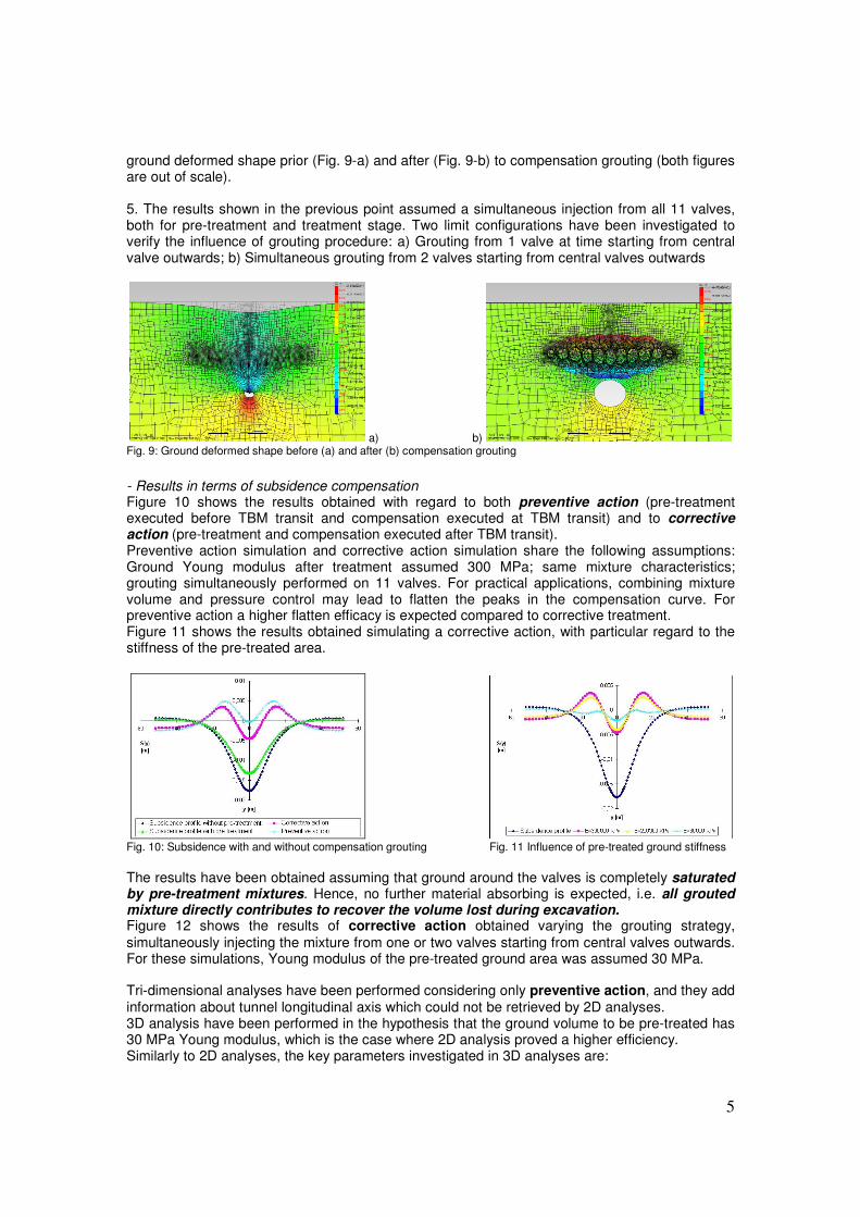
5
ground deformed shape prior (Fig. 9-a) and after (Fig. 9-b) to compensation grouting (both figures are out of scale). 5. The results shown in the previous point assumed a simultaneous injection from all 11 valves, both for pre-treatment and treatment stage. Two limit configurations have been investigated to verify the influence of grouting procedure: a) Grouting from 1 valve at time starting from central valve outwards; b) Simultaneous grouting from 2 valves starting from central valves outwards
a) b) Fig. 9: Ground deformed shape before (a) and after (b) compensation grouting
- Results in terms of subsidence compensation Figure 10 shows the results obtained with regard to both preventive action (pre-treatment executed before TBM transit and compensation executed at TBM transit) and to corrective action (pre-treatment and compensation executed after TBM transit). Preventive action simulation and corrective action simulation share the following assumptions: Ground Young modulus after treatment assumed 300 MPa; same mixture characteristics; grouting simultaneously performed on 11 valves. For practical applications, combining mixture volume and pressure control may lead to flatten the peaks in the compensation curve. For preventive action a higher flatten efficacy is expected compared to corrective treatment. Figure 11 shows the results obtained simulating a corrective action, with particular regard to the stiffness of the pre-treated area.
Fig. 10: Subsidence with and without compensation grouting
Fig. 11 Influence of pre-treated ground stiffness
The results have been obtained assuming that ground around the valves is completely saturated by pre-treatment mixtures. Hence, no further material absorbing is expected, i.e. all grouted mixture directly contributes to recover the volume lost during excavation. Figure 12 shows the results of corrective action obtained varying the grouting strategy,
simultaneously injecting the mixture from one or two valves starting from central valves outwards. For these simulations, Young modulus of the pre-treated ground area was assumed 30 MPa. Tri-dimensional analyses have been performed considering only preventive action, and they add information about tunnel longitudinal axis which could not be retrieved by 2D analyses. 3D analysis have been performed in the hypothesis that the ground volume to be pre-treated has 30 MPa Young modulus, which is the case where 2D analysis proved a higher efficiency. Similarly to 2D analyses, the key parameters investigated in 3D analyses are:
6
• Definition of mixture volume required for compensation
• Definition of the compensation strategy in accordance with excavation advance (dynamic aspect of the problem)
- Grouting volume First of all, longitudinal settlement profile along the tunnel axis is determined. From the profile, the expected maximum settlement can be estimated for each excavation advance step. The Gaussian distribution relative to transverse direction with regard to tunnel axis is then determined at each intermediate station between valves (spaced 1.5 m). The maximum settlement for the transverse section is derived from the longitudinal profile, previously defined, at the reference transverse section. The maximum required mixture volume is given by the sum of the series of volumes to be grouted at each step advance and is comparable to the volume obtained from 2D analysis, which represent the limit condition of the problem.
Fig. 12: grouting strategy influence
Fig. 13: Step 2: settlement along longitudinal axis before and after compensation grouting
- Dynamic process Another key feature of the process is excavation dynamicity. In 3D modeling, compensation grouting is performed when the measured movement exceeds pre-defined threshold limits. Compensation is not necessarily performed at the end of excavation process, i.e. when the ground reaches the final equilibrium condition. Compensation might instead be performed during excavation advance stage, at a certain distance from tunnel face, and takes into account the local values of ground characteristics and excavation parameters. Injection and re-injection modeling requires mesh compatibility between the mesh used for excavation simulation stage and the mesh used to model the expansion of each single valve. The overall activation of grouting process has to be observed on the whole transverse section at simultaneous injection of more than one valve. If the valves are activated after a series of excavation advance steps, the number of valves to be simultaneously activated in the longitudinal direction increases with the number of consecutive excavation steps. - Subsidence recovers results Figures 13 and 14 show a summary of some results obtained with regard to settlement compensation by applying the concepts described in the paper. Figures show movements recorded before and after compensation grouting. At each step, that includes 4 excavation stages, the loss volume at each reference valve has been computed and compared with the threshold value. If the calculated values exceeded pre-defined limits grouting process has been activated. Within a distance of 10 meters across shield tail, valves have never been activated not to damage coating ring. Figure 13 refers as an example to the step n°2 and show first grouting effect only. Re-activation procedure has been applied to reference valves at step 2 during step 5 (Fig. 14). The oscillation between small uplift and subsidence in the longitudinal profile is due to the difference between volumes grouted one or more times and to the presence of the not-injectable zones. Nevertheless, the overall compensation result can be regarded as highly satisfactory. A final interesting remark is shown in Figure 15 where transverse section compensation curves obtained by 2D analysis and 3D analysis are compared. The final result is considered satisfactory
7
and in line with what expected and the difference between the recovered obtained by the analyses and the optimal theoretical recover could be reduced modifying grouting volumes.
Fig. 14: Step 5: settlement along longitudinal axis with re-activation of valves of step 2
Fig. 15: transverse settlement curve: 2D analysis and 3D analysis results comparison
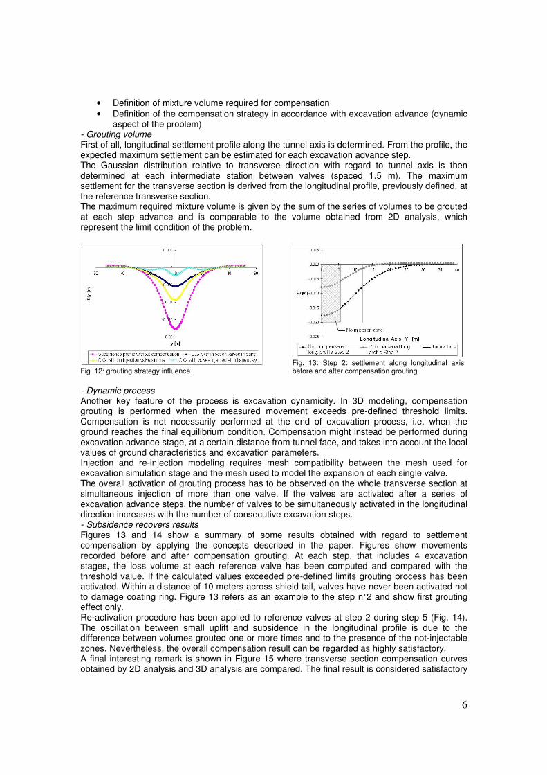
4 Concluding remarks The procedure described in the paper has been applied to “Building 166” of the high speed underground rail link of Florence. Analyses showed that a preventive action is necessary and to be activated, during excavation advance, to all valves within the TBM advance step, while it operates in the building reference area. Grouting shall be repeated to recover step by step the decompression induced by excavation advance. Grouting shall be performed after pre-treatment in order to avoid mixture dispersion due to void saturation. The generalization of the case study may represent a useful guide for the definition of procedures to be adopted to verify the effects of compensation techniques. Study key features are summarized in Figure 16.
Fig. 16: Compensation grouting simulation highlights
Simulation results represent just an initial predictive tool which has to be necessarily adjusted by means of on-site measurements which require sophisticated monitoring instrumentation to be installed on the superstructures of interest, and able to associate excavation induced effects with excavation machinery control parameters. As a result, the real time monitoring system is a “must” and represents the only practical tool to verify the effect induced by compensative techniques applied.

8
References [1] Ata A.A, Ground settlements induced by slurry shield tunnelling in stratified soils, Proc. North
American Tunnelling ’96, Ed L Ozdemir,1996 [2] Attewell P.B, Woodman J.P, Predicting the dynamics of ground settlement and its derivatives
caused by tunnelling in soil, Ground Engineering, 1982 [3] Boscardin M. D, Cording E. G, Building response to excavation-induced settlement, ASCE,
1989 [4] Burland J.B, Standing J.R, Jardine F.M, Building response to tunnelling, Case studies from
construction of the Jubilee Line Extension, London. Volume 1: Projects and methods, Ed. Thomas Telford, 2001
[5] Burland J.B, Standing J.R, Jardine F.M, Building response to tunnelling, Case studies from construction of the Jubilee Line Extension, London. Volume 2: Case studies, Ed. Thomas Telford, 2001
[6] Castellanza R, Betti D, Lambrughi A, Three-dimensional numerical models for mechanised excavations in urban areas, Jornada Técnica: Túneles con EPB. Simulación y Control de la Tuneladora. Barcellona, 2005
[7] Clough G.W. e Schmidt B, Design and performance of excavations and tunnels in soft clays, In Soft Clay Engineering, Elsevier, 1981
[8] Henn Raymond W, Practical guide to grouting of underground structures, Ed. ASCE Press and Thomas Telford, 1996
[9] Kummerer C, Thurner R, Rigazio A, Zamagni A, Compensation grouting as measure for the tunnel excavation in urban areas for railway bridges, 14th European Conference on Soil Mechanics and Geotechnical Engineering, Madrid, Spain, 24-27 September 2007
[10] Mair R. J, Taylor R. N, Bored tunnelling in the urban environment, The 14th International Conference on Soil Mechanics and Foundation Engineering, Hamburg September 1997
[11] Midas/GTS, Analysis reference Manual, Midas/GTS vers. 2.5.1, 2008 [12] Midas/GTS, Getting started Manual, Midas/GTS vers. 2.5.1, 2008 [13] New B.M. e O’Reilly M.P, Tunnelling induced ground movements; predicting their magnitude
and effects, 4th International Conference on Ground Movements and Structures, Cardiff, Pentech Press, 1991
[14] Nomoto T, Mori H, Matsumoto M, Overview on ground movements during shield tunnelling – a survey on Japanese shield tunnel, Underground Construction in soft ground, London, Balkema, 1995
[15] O’Reilly M.P. e New B.M, Settlements above tunnels in the United Kingdom – their magnitude and prediction, Tunnelling 82, London 1982
[16] Peck R. B, Deep excavation and tunnelling in soft ground, Proc. 7th International Conference on Soil Mechanics and Foundation Engineering - State of Art Volume, Mexico City, 1969.
[17] Pigorini A, Iannotta F, Martelli F, Pedone E. M, Sciotti A, Il nodo ferroviario AV/AC di Bologna. Le scelte progettuali: le gallerie con scavo meccanizzato (lotto 5), Gallerie e grandi opere sotterranee n.81, marzo 2007
[18] Romero V.S, Hansmire W.H, New methods for building protection from settlement due to underground transit contruction, Articles & Pubblications – Jacobs Associates Published Documents & Press Coverage, 2003
[19] Warner J, Practical handbook of grouting: soil, rock, and structures, Ed. John Wiley & Sons, Inc. 2004