study course for home appliances - repair manualsrepairmanuals.yolasite.com/resources/basic...
TRANSCRIPT

STUDY COURSEfor Home Appliances
HOW TO READ:• TIMER SEQUENCE CHARTS (ESTERLINE)• WIRING DIAGRAMS
BASIC ELECTRICITY
11 12 9 13 4 6 14 10 7 8 19 23 16 3 5 2 1 sw.
2 2 WASH FILL WASH
4 4 PAUSE
DRAIN
6 6
8 8 WASH FILL WASH
10 10
BLEACH
12 12
SUDS STORE DRAIN
14 14 SPRAY
16 16 RINSE FILL
RINSE
18 18 DRAIN
SPRAY
20 20 SPIN
22 22
24 24
TE
RM
SW
ITC
H F
UN
CT
.
MACHINE FUNCTION
TERMINALCODES
TIMER SWITCHFUNCTIONSTIMER SWITCH
NUMBERS
RE
GU
LA
R/H
EA
VY
OR
NO
RM
AL
SU
PE
RW
AS
HC
YC
LE
OFF
RINSE FILL
SPIN
BR
WA
SH
FIL
L
Y -
RR
INS
E F
ILL
LB
US
UD
S R
ET
.
G -
BK
SP
RA
Y
O -
BK
RIN
SE
CO
ND
.
OR
ME
D. M
OT
OR
GY
SP
IN
G -
BK
DE
EP
FIL
L
YA
GIT
AT
E
LB
US
UD
S S
TO
RE
BU
- O
AG
IT. M
OT
OR
R -
WS
PIN
MO
TO
R
TT
IME
R
BU
- G
BL
EA
CH
BU
HI -
MO
TO
R
TM
BY
- P
AS
S
- -
TO
OL
ED
CA
M
W -
GM
AS
TE
R
CH
AR
T
Module 3LIT 787741 Rev. B
TIMERFUNCTION
SWITCHCLOSED
SWITCHOPEN
TERMINALCODE
SWITCHNUMBER
All rights reserved. No portion of this book may be reproduced in any form withoutwritten permission from WHIRLPOOL CORPORATION.
© 1989, 1993, 2000 WHIRLPOOL CORPORATION
WHIRLPOOL CORPORATION does not assume any responsibilityor any liability in connection with the use of this manual.
® The trademarks WHIRLPOOL , , , and FSP are registeredtrademarks of Whirlpool Corporation.

INTRODUCTION
The material presented in this module is intended to provide you with an understanding of thefundamentals of electricity as applied to major appliances.
Major appliances have become more sophisticated, taking them out of the screwdriver and pliers category.Their electrical circuits include several different types of automatic controls, switches, heaters, valves, etc..Semiconductors, solid-state controls, and other components usually associated with radio and televisionelectronic circuits, are being engineered into automatic washers, dryers, dishwashers, and refrigerators.
The appliance technician is emerging into a professional status of his own. He must prepare himself nowto be able to perform his duties today as well as to retain his professionalism in the future.
No longer is on-the-job training sufficient to prepare technicians for the complicated procedures requiredfor todays sophisticated appliances. This training can best be obtained through organized classroom studyand application. However, much of the knowledge necessary to service todays appliances can be obtainedthrough study courses. Completion of this and other courses will provide you with sufficient understanding ofappliances and their operation to enable you to do minor service. It will also serve as a valuable steppingstone to more advanced study and on-the-job training to improve your servicing skills.
Information contained in this module is used on WHIRLPOOL® appliances.
1

TABLE of CONTENTS
PAGE
CHAPTER 1 ..............................................................................................3Timer Sequence Charts (Esterline)
CHAPTER 2 ..............................................................................................7Wiring Diagrams
*TEST ............................................................See Test Book LIT787743
*NOTE: We recommend taking the TEST for MODULE 3, rightafter studying it.
2

CHAPTER 1
TIMER SEQUENCE GHARTS(ESTERLINE)
3
Page 5 represents a sample timer sequence chart.Page 6 represents a sample wiring diagram. Thisdetailed chart shows how the timer motor and timerswitch operation control machine functions. Whenthe timer switch sequence chart information is com-pared to the wiring diagram, electrical and mechani-cal diagnosis can be accomplished. The top horizontalrow of numbers across the top of the timer sequencechart represents timer SWITCH NUMBERS. Thesenumbers will not be found on the actual timer. Theyare merely guides to be used to relate between thetimer sequence chart and the wiring diagram. Thetimer switch functions are shown directly below thetimer switch numbers. These relate to the functioncontrolled by that switch contact.
The letters below the timer switch functions, such asLBU, GY, G-BK, O-BK, etc., represent the actualtimer terminal markings and wiring color code.
The vertical column at the right of the timer sequencechart shows the cycles of machine operation. As youcan see, in this particular chart we are only showingthree Cycles — NORMAL or REGULAR/HEAVY,GENTLE and PERMANENT PRESS, as well as thespecial cycle — SUPER WASH. To the right of eachcycle are the machine functions for that cycle.
The columns under the machine function headinggive the basic operation on the left, and give thesupporting functions on the right, for each timer step.
Even numbered timer steps are shown to the left ofthe wash cycles. The odd number steps are not shown,to avoid confusion and an overcrowded appearance.Each timer space represents a definite period of time.
Closed switches for the components of each timer stepare represented by the HEAVY VERTICAL BARS inthe timer switch sequence chart.
The timer switch sequence chart explains the when,what, why, and how of machine function at anyselected point of operation.
In order to properly diagnose a problem, the electricalcircuitry and the wiring diagram, attached to theproduct must be thoroughly understood. Let’s firststudy each part of the wiring diagram.
On page 6 the symbol shown at the top of the page bythe letters BK, G, and W represents the line cordattachment plug. The line marked W extends downthe right side of the diagram and is known as theneutral side of the electrical system. Note that thisline connects directly to one side of each energyconverting (electrical to mechanical) component ofthe automatic washer, without any controlling switch.
The line shown as BK extends to the left and is knownas the hot side of the electrical system. It provides acircuit to the master switch (No. 1) and to all the otherelectrically operated components through the timerswitches, and/or the water level and temperatureswitches.
The heavy black lines connected to numbered switchesrepresent circuits and switches within the timerassembly.
The pull-on, push-off timer knob switch controls allcircuits. This switch will start the automatic washeroperation when the timer knob is pulled out, and willstop the operation when it is pushed in.
All timer switches are numbered to correspond withthe timer sequence chart. Any given machine compo-nent is always controlled by the same timer switchnumber, regardless of the model. For example: Five(5) is always reserved for high motor speed; seven (7)is always reserved for agitation, etc.
Wiring harnesses are color coded, to match the colorcoded lettering imprinted on the wires of the timerterminal connections. Any given automatic washercomponent always uses the same wiring harnesscolor and color code lettering, regardless of model.Example: BU (Blue) is always used for high motorspeed; Y (Yellow) is always used for agitation.
Any given component is always shown at the sameposition on the wiring diagram. The water tempera-ture switch is shown within dashed lines, near thebottom of the wiring chart. The lettering at the rightof the switch contacts indicates present contacts forvarious combinations of wash and rinse water tem-perature selections. The first letter represents WASHwater temperature, while the second letter identifiesRINSE water temperature.

4
Since studying and learning information has no valueuntil it is applied, let’s follow this step-by-step proce-dure to diagnose a machine malfunction.
For an example, say the washer was set in theGENTLE cycle with the water temperature switchset at HOT WASH and COLD RINSE, and that thewasher will not FILL. A rule is to always check theeasy and obvious first.
Is there power to the machine? Be sure the machinespower cord is plugged into a live wall receptacle.Next, be sure the water faucets are turned On! Also,make sure the timer dial indication coincides withthe timer function.
Let’s assume in our example that, having completedall the normal examinations, the machine still doesnot FILL. Turn to the wiring diagram and timersequence chart. By using this information, you will beable to determine which circuits and components areaffected in the appliances electrical system at anygiven time. The wiring chart is easy to follow when astep-by-step checking sequence is used.
Fill, in the GENTLE cycle, takes place in timer Step26. Let’s start by drawing a line horizontally throughtimer Step 26 on the timer sequence chart and notethe closed circuits.
The closed switches are switch no. 1 (master), no. 16(timer), no. 19 (agitate motor), no. 7 (agitate), no. 10(deep fill) and switch no. 11 (wash fill).
Now close these switches on the wiring diagram onpage 6. As you can see by the heavy line, the electric-ity on the “BK” side of the line flows through switchno. 1, the water level switch (empty), temperatureswitch and the mixing valve and then back throughthe “W” side of the line, completing a circuit.
Since our problem is “No Fill,” the first thing to do isturn your timer dial to the start of the GENTLE cycle.
Did the light, if used, turn on? If so, timer switch no.1 is ok. Now turn your timer dial to SPIN and pull theknob out. Did your automatic washer start to spin? Ifso, the water level switch is ok. Now you will have tocheck out timer switches no. 10 and no. 11, thetemperature switch and the mixing valve to find andcorrect the problem.
When the correct water level is reached, the switchtrips from “P” (empty) to “T” (full).
With the water level switch tripping from “P” to “T,”there is no electricity through switches no. 10 and no.11, temperature switch and the mixing valve.
Electricity flows from the “BK” side of the line throughswitch no. 1, the water level switch (full), agitatesolenoid, speed switch/drive motor and timer motorall at the same time, completing a circuit through the“W” side of the line.
You can also see when switch no. 1 is closed. Thiscompletes a circuit through the ballast and fluores-cent lamp, no matter what the water level switch isdoing.

5
SAMPLE TIMER SEQUENCE CHART(ESTERLINE)
11 12 9 13 4 6 14 10 7 8 19 23 16 3 5 2 1 sw.
2 2 WASH FILL WASH
4 4 PAUSE
DRAIN
6 6
8 8 WASH FILL WASH
10 10
BLEACH
12 12
SUDS STORE DRAIN
14 14 SPRAY
16 16 RINSE FILL
RINSE
18 18 DRAIN
SPRAY
20 20 SPIN
22 22
24 24
26 26
WASH FILL WASH
28 28
SUDS STORE DRAIN
30 30 SPRAY SPIN
RINSE FILL
32 32 RINSE
DRAIN
34 34
36 36
OFF
38 38
40 40 WASH FILL WASH
42 42 PAUSE
DRAIN
44 44
46 46 WASH FILL WASH
TE
RM
SW
ITC
H F
UN
CT
.
MACHINE FUNCTION
TERMINALCODES
TIMER SWITCHFUNCTIONSTIMER SWITCH
NUMBERS
RE
GU
LA
R/H
EA
VY
OR
NO
RM
AL
PE
RM
AN
EN
TP
RE
SS
GE
NT
LE
SU
PE
RW
AS
HS
UP
ER
WA
SH
CY
CL
E
TIMERSTEPS
MACHINE FUNCTION(EMPTY)
MACHINE FUNCTION(FULL)
TIMERSTEPS
RINSE FILL
SPIN
OFF
RINSE FILL
SPIN
SWITCH OPENINGS AND CLOSINGS
BR
WA
SH
FIL
L
Y -
RR
INS
E F
ILL
LB
US
UD
S R
ET
.
G -
BK
SP
RA
Y
O -
BK
RIN
SE
CO
ND
.
OR
ME
D. M
OT
OR
GY
SP
IN
G -
BK
DE
EP
FIL
L
YA
GIT
AT
E
LB
US
UD
S S
TO
RE
BU
- O
AG
IT. M
OT
OR
R -
WS
PIN
MO
TO
R
TT
IME
R
BU
- G
BL
EA
CH
BU
HI -
MO
TO
R
TM
BY
- P
AS
S
- -
TO
OL
ED
CA
M
W -
GM
AS
TE
R
TIM
ER
SW
ITC
H S
EQ
UE
NC
E C
HA
RT
CYCLE

11 12 9 13 4 6 14 10 7 8 19 23 16 3 5 2 1 sw.
2 2 WASH FILL WASH
4 4 PAUSE
DRAIN
6 6
8 8 WASH FILL WASH
10 10
BLEACH
12 12
SUDS STORE DRAIN
14 14 SPRAY
16 16 RINSE FILL
RINSE
18 18 DRAIN
SPRAY
20 20 SPIN
TE
RM
SW
ITC
H F
UN
CT
.
MACHINE FUNCTION
TERMINALCODES
TIMER SWITCHFUNCTIONSTIMER SWITCH
NUMBERS
RE
GU
LA
R/H
EA
VY
OR
NO
RM
AL
SU
PE
RW
AS
HC
YC
LE
RINSE FILL
SPIN
BR
WA
SH
FIL
L
Y -
RR
INS
E F
ILL
LB
US
UD
S R
ET
.
G -
BK
SP
RA
Y
O -
BK
RIN
SE
CO
ND
.
OR
ME
D. M
OT
OR
GY
SP
IN
G -
BK
DE
EP
FIL
L
YA
GIT
AT
E
LB
US
UD
S S
TO
RE
BU
- O
AG
IT. M
OT
OR
R -
WS
PIN
MO
TO
R
TT
IME
R
BU
- G
BL
EA
CH
BU
HI -
MO
TO
R
TM
BY
- P
AS
S
- -
TO
OL
ED
CA
M
W -
GM
AS
TE
R
6
SAMPLE WIRING DIAGRAM
16
(OPEN)
(OPEN)
(OPEN)
(OPEN)
(OPEN)
(OPEN)
(OPEN) (OPEN)
(OPEN)14
13 12
10 11
8
9
(CLOSED) (CLOSED)
(CLOSED)
(CLOSED)
(CLOSED)
1
2
3
4
5
6
7
23
19
(OPEN)(CLOSED)
CABINET GROUND
BK
G
W
STARTER
BALLAST
W W
RR
FLUORESCENT LAMP
TIMER MOTOR
TM TM-W
BLEACH SOLENOID
FABRIC COND. SOLENOID
BU-G
O-BK
W-G
BK
V
PULL-ONPUSH-OFF
TIMERKNOB SW.
SPEEDCONTROLSWITCH
BUBU
BU-O
HI
DRIVEMOTOR
MED.
OR
R-WLO
GY-P
AGITATESOLENOID
Y
SUDS VALVE(IF USED)LBU
(IF USED)
T
FULL
EMPTY
WATERLEVEL
SWITCH
G-Y LIDSWITCH
SPINSOLENOID
G-BK
BR
Y-R W
BR-RHOT
VALVE
RCOLDVALVE
TEMP. SW.(CLOSED IN
POSITIONS NOTED)HW
WCCCWW
WWHWWCWWHC
B
S

CHAPTER 2
WIRING DIAGRAMSIn this chapter each page is a typical wiring diagram. You will find the response on theback of the page.
Let’s take a look at a wiring diagram for an automatic washer. Note switch number 1 onthe diagram. It is first in line and is the master switch. No circuits are energized when thedial is in the off position. Turn the dial to any operating position and one circuit isenergized even before you operate the push-pull switch by pulling the knob.
WITH YOUR PENCIL, CLOSE SWITCH 1 AND DRAW A WAVY LINE THROUGH THEENERGIZED CIRCUIT.
7
CABINET GROUND
BK
G
W
STARTER
BALLAST
W W
RR
FLUORESCENT LAMP
TIMER MOTOR
TM TM-W
FABRIC COND. SOLENOID
BU-G
O-BK
W-G
BK
V
PULL-ONPUSH-OFF
TIMERKNOB SW.
SPEEDCONTROLSWITCH
BUBU
BU-O
HI
DRIVEMOTOR
MED.
OR
R-WLO
GY-P
AGITATESOLENOID
Y
SUDS VALVE(IF USED)LBU
(IF USED)
T
FULL
EMPTY
WATERLEVEL
SWITCH
SWITCH OPEN
G-BK
BR
BR-RHOT
VALVETEMP. SW.(CLOSED IN
POSITIONS NOTED)HW
WCCCWW
WWHWWCWWHC
B
S
1
2
3
4
5
6
7
8
9
19
23
16BLEACH SOLENOID
SWITCH #1

CABINET GROUND
BK
G
W
STARTER
BALLAST
W W
RR
FLUORESCENT LAMP
TIMER MOTOR
TM TM-W
FABRIC COND. SOLENOID
BU-G
O-BK
W-G
BK
V
PULL-ONPUSH-OFF
TIMERKNOB SW.
SPEEDCONTROLSWITCH
BUBU
BU-O
HI
DRIVEMOTOR
MED.
OR
R-WLO
GY-P
AGITATESOLENOID
Y
SUDS VALVE(IF USED)LBU
(IF USED)
T
FULL
EMPTY
WATERLEVEL
SWITCH
SWITCH OPEN
SWITCH CLOSED
G-Y LIDSWITCH
SPINSOLENOID
G-BK
BR
Y-R W
BR-RHOT
VALVE
RCOLDVALVE
TEMP. SW.(CLOSED IN
POSITIONS NOTED)HW
WCCCWW
WWHWWCWWHC
B
S
1
2
3
4
5
6
7
8
9
19
23
16BLEACH SOLENOID
SWITCH #1
CABINET GROUND
BK
G
W
STARTER
BALLAST
W W
RR
FLUORESCENT LAMP
TIMER MOTOR
TM TM-W
FABRIC COND. SOLENOID
BU-G
O-BK
W-G
BK
V
PULL-ONPUSH-OFF
TIMERKNOB SW.
SPEEDCONTROLSWITCH
BUBU
BU-O
HI
DRIVEMOTOR
MED.
OR
R-WLO
GY-P
AGITATESOLENOID
Y
T
FULL
B
S
1
2
3
4
5
6
7
8
19
23
16BLEACH SOLENOID
SWITCH #1
8
OR

9
You did so well with that last circuit that we can progress to more involved circuits. Let’sassume that you have selected the “wash” cycle that gives you hi-motor agitaiton, yourwater temperature, and have started the washer. The timer has advanced to a positionwhere it has closed timer switches 1, 5, 7, 10, 11, and 16.
In the diagram below we have closed the proper contacts in the water temperature switch.
WITH TIMER SWITCHES 1, 5, 7, 10, 11, AND 16 CLOSED, TRACE THE CIRCUITSWITH A WAVY LINE.
SPIN SOLENOID14
13 12
RGY R
Y-R COLD VALVE
LID SWITCH
Y-R
W
G-BK
10 11BR
P P2
EMPTY
FULL
P
V
T
T2T8
J
J
9
SUDS VALVE
HOT VALVE
BR-R
TEMP. SWITCH(CLOSED INPOSITIONS
NOTED)* 5 TEMP. ONLY
HC WC
HW WW*
CC WCWW*
DRIVE MOTOR
HI
LO
BU
OR6
5
716
Y Y
AGITATE SOLENOID
TIMER MOTOR
TM-WTM TM
CABINET GROUND
BK
G
W
1A 1
V2 V V
BKV3
V3
25
2
SUDS
SUDSPULL-ONPUSH-OFF
TIMER KNOBSWITCH

10
SPIN SOLENOID14
13 12
RGY R
Y-R COLD VALVE
LID SWITCH
Y-R
W
G-BK
10 11BR
P P2
EMPTY
FULL
P
V
T
T2T8
J
J
9
SUDS VALVE
HOT VALVE
BR-R
TEMP. SWITCH(CLOSED INPOSITIONS
NOTED)* 5 TEMP. ONLY
HC WC
HW WW*
CC WCWW*
DRIVE MOTOR
HI
LO
BU
OR6
5
716
Y Y
AGITATE SOLENOID
TIMER MOTOR
TM-WTM TM
CABINET GROUND
BK
G
W
1A 1
V2 V V
BKV3
V3
25
2
SUDS
SUDSPULL-ONPUSH-OFF
TIMER KNOBSWITCH

11
SPIN SOLENOID14
13 12
RGY R
Y-R COLD VALVE
LID SWITCH
Y-R
W
G-BK
10 11BR
P P2
EMPTY
FULL
P
V
T
T2T8
J
J
9
SUDS VALVE
HOT VALVE
BR-R
TEMP. SWITCH(CLOSED INPOSITIONS
NOTED)* 5 TEMP. ONLY
HC WC
HW WW*
CC WCWW*
DRIVE MOTOR
HI
LO
BU
OR6
5
716
Y Y
AGITATE SOLENOID
TIMER MOTOR
TM-WTM TM
CABINET GROUND
BK
G
W
1A 1
V2 V V
BKV3
V3
25
2
SUDS
SUDSPULL-ONPUSH-OFF
TIMER KNOBSWITCH
Very good! In the last diagram the washer was filling with water. By looking at theresponse you can see that neither the main drive motor, agitate solenoid, nor the timermotor circuits were energized. In the diagram below the water level switch has moved tothe FULL position because the washer has filled with water. The same timer switches thatwere closed in the last diagram are closed. We have closed them for you.
DRAW A WAVY LINE THROUGH THE ENERGIZED CIRCUITS BELOW.

12
SPIN SOLENOID14
13 12
RGY R
Y-R COLD VALVE
LID SWITCH
Y-R
W
G-BK
10 11BR
P P2
EMPTY
FULL
P
V
T
T2T8
J
J
9
SUDS VALVE
HOT VALVE
BR-R
TEMP. SWITCH(CLOSED INPOSITIONS
NOTED)* 5 TEMP. ONLY
HC WC
HW WW*
CC WCWW*
DRIVE MOTOR
HI
LO
BU
OR6
5
716
Y Y
AGITATE SOLENOID
TIMER MOTOR
TM-WTM TM
CABINET GROUND
BK
G
W
1A 1
V2 V V
BKV3
V3
25
2
SUDS
SUDSPULL-ONPUSH-OFF
TIMER KNOBSWITCH

13
SPIN SOLENOID14
13 12
RGY R
Y-R COLD VALVE
LID SWITCH
Y-R
W
G-BK
10 11BR
P P2
EMPTY
FULL
P
V
T
T2T8
J
J
9
SUDS VALVE
HOT VALVE
BR-R
TEMP. SWITCH(CLOSED INPOSITIONS
NOTED)* 5 TEMP. ONLY
HC WC
HW WW*
CC WCWW*
DRIVE MOTOR
HI
LO
BU
OR6
5
716
Y Y
AGITATE SOLENOID
TIMER MOTOR
TM-WTM TM
CABINET GROUND
BK
G
W
1A 1
V2 V V
BKV3
V3
25
2
SUDS
SUDSPULL-ONPUSH-OFF
TIMER KNOBSWITCH
You are doing very well! Now let’s suppose the timer has advanced and closed timerswitches 1, 2, 5, 14, and 16. The LID SWITCH is also closed because the lid is shut. Thisputs the washer in the SPIN cycle. We have closed the switch contacts in the watertemperature switch for you as we have done in the past diagrams.
SINCE SWITCHES 1, 2, 5,14, AND 16 ARE CLOSED, TRACE THE CIRCUITS BELOWWITH A WAVY LINE.

14
SPIN SOLENOID14
13 12
RGY R
Y-R COLD VALVE
LID SWITCH
Y-R
W
G-BK
10 11BR
P P2
EMPTY
FULL
P
V
T
T2T8
J
J
9
SUDS VALVE
HOT VALVE
BR-R
TEMP. SWITCH(CLOSED INPOSITIONS
NOTED)* 5 TEMP. ONLY
HC WC
HW WW*
CC WCWW*
DRIVE MOTOR
HI
LO
BU
OR6
5
716
Y Y
AGITATE SOLENOID
TIMER MOTOR
TM-WTM TM
CABINET GROUND
BK
G
W
1A 1
V2 V V
BKV3
V3
25
2
SUDS
SUDSPULL-ONPUSH-OFF
TIMER KNOBSWITCH

15
You did so well with the automatic washer diagrams that you should have no trouble witha wiring diagram for an electric clothes dryer.
In the wiring diagram below the customer has selected the “REGULAR” drying cycle byturning the timer dial and has closed the dryer door. However, she has not pushed the“Push-to-Start” relay yet.
At the instant of start, when she pushes the “Push-to-Start” relay, which circuits areenergized?
We have closed the timer switches for you.
WITH YOUR PENCIL, TRACE THE ACTIVE CIRCUITS BELOW WITH A WAVY LINE.
RAH
AH1
AH3
AH2
TIMER
TEMP. SELECTOR SW.
1.2 K
N.C.
HT1
HT3 HS1
HS3
N.C.
OPERATINGTHERMOSTAT
HI LIMITTHERMOSTAT
HEATER
TIMER MOTOR
THERMOSTAT HEATER
BH BH1
H1 H2
RS
POWERRESISTOR
RS
2M
1M
CENTRIFUGALSWITCH
TM CS
CT1
L2
N
R2 R1 D1 D
DOOR SW.P.T.S.
RELAYDRIVE MOTOR
THERMAL-FUSENOT RESETTABLE
4M FS1 FS3
L1
BS BS1
BUZZER
Y
BG
RE
6M
5M
T
B
240 VOLTS
120 VOLTS

16
RAH
AH1
AH3
AH2
TIMER
TEMP. SELECTOR SW.
1.2 K
N.C.
HT1
HT3 HS1
HS3
N.C.
OPERATINGTHERMOSTAT
HI LIMITTHERMOSTAT
HEATER
TIMER MOTOR
THERMOSTAT HEATER
BH BH1
H1 H2
RS
POWERRESISTOR
RS
2M
1M
CENTRIFUGALSWITCH
TM CS
CT1
L2
N
R2 R1 D1 D
DOOR SW.P.T.S.
RELAYDRIVE MOTOR
THERMAL-FUSENOT RESETTABLE
4M FS1 FS3
L1
BS BS1
BUZZER
Y
BG
RE
6M
5M
T
B
240 VOLTS
120 VOLTS

17
The wiring diagram on this page shows the circuits that are made with the dryer runningin the “REGULAR” cycle. We have closed the proper switches for this condition for you.
DRAW A WAVY LINE THROUGH ALL OF THE ACTIVE CIRCUITS IN THE WIRINGDIAGRAM BELOW.
RAH
AH1
AH3
AH2
TIMER
TEMP. SELECTOR SW.
1.2 K
N.C.
HT1
HT3 HS1
HS3
N.C.
OPERATINGTHERMOSTAT
HI LIMITTHERMOSTAT
HEATER
TIMER MOTOR
THERMOSTAT HEATER
BH BH1
H1 H2
RS
POWERRESISTOR
RS
2M
1M
CENTRIFUGALSWITCH
TM CS
CT1
L2
N
R2 R1 D1 D
DOOR SW.P.T.S.
RELAYDRIVE MOTOR
THERMAL-FUSENOT RESETTABLE
4M FS1 FS3
L1
BS BS1
BUZZER
Y
BG
RE
6M
5M
T
B
240 VOLTS
120 VOLTS

18
Did you show the buzzer circuit as an active circuit? Remember, it is a basic principle ofelectricity that current will always follow the path of least resistance. In this case thecurrent bypassed the buzzer circuit and flowed through timer contacts Y-BG and the drivemotor circuit — a line of least reistance.
RAH
AH1
AH3
AH2
TIMER
TEMP. SELECTOR SW.
1.2 K
N.C.
HT1
HT3 HS1
HS3
N.C.
OPERATINGTHERMOSTAT
HI LIMITTHERMOSTAT
HEATER
TIMER MOTOR
THERMOSTAT HEATER
BH BH1
H1 H2
RS
POWERRESISTOR
RS
2M
1M
CENTRIFUGALSWITCH
TM CS
CT1
L2
N
R2 R1 D1 D
DOOR SW.P.T.S.
RELAYDRIVE MOTOR
THERMAL-FUSENOT RESETTABLE
4M FS1 FS3
L1
BS BS1
BUZZER
Y
BG
RE
6M
5M
T
B
240 VOLTS
120 VOLTS
19
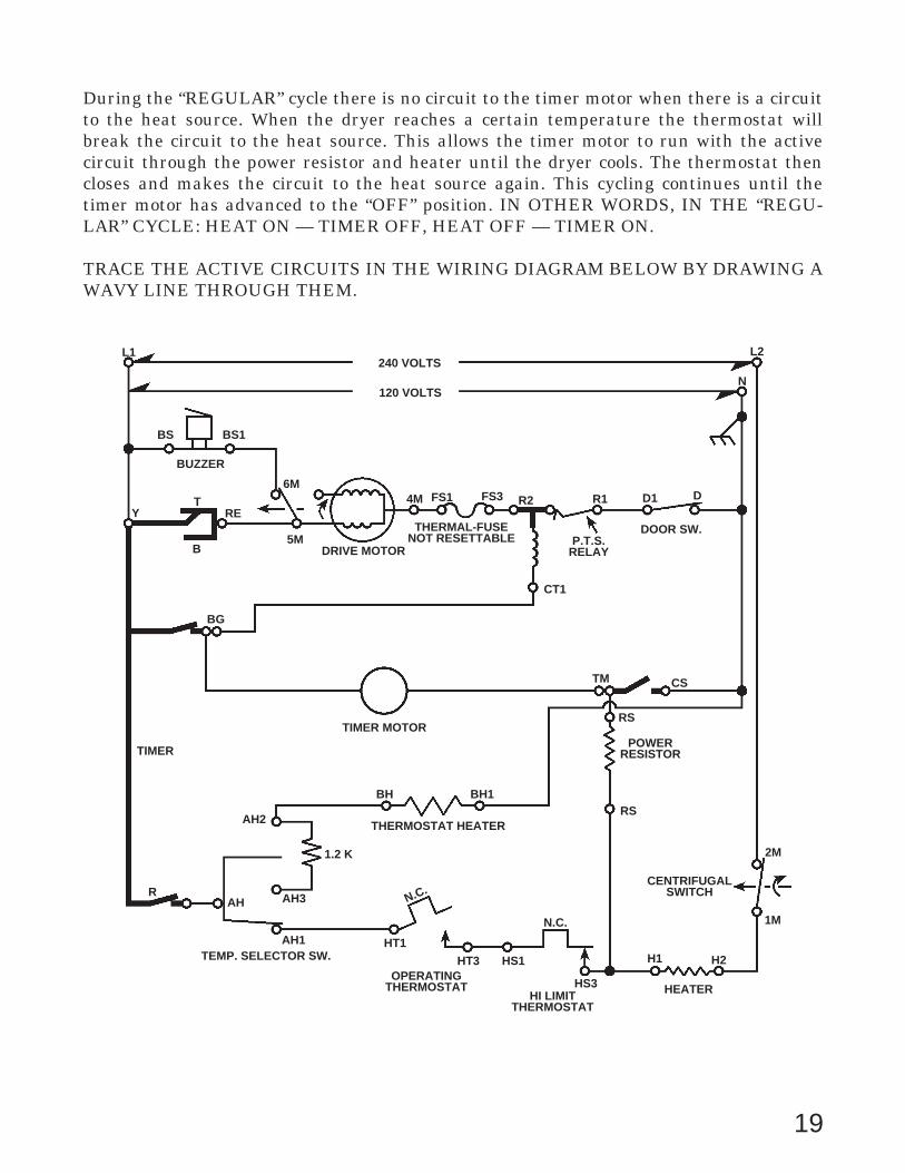
During the “REGULAR” cycle there is no circuit to the timer motor when there is a circuitto the heat source. When the dryer reaches a certain temperature the thermostat willbreak the circuit to the heat source. This allows the timer motor to run with the activecircuit through the power resistor and heater until the dryer cools. The thermostat thencloses and makes the circuit to the heat source again. This cycling continues until thetimer motor has advanced to the “OFF” position. IN OTHER WORDS, IN THE “REGU-LAR” CYCLE: HEAT ON — TIMER OFF, HEAT OFF — TIMER ON.
TRACE THE ACTIVE CIRCUITS IN THE WIRING DIAGRAM BELOW BY DRAWING AWAVY LINE THROUGH THEM.
RAH
AH1
AH3
AH2
TIMER
TEMP. SELECTOR SW.
1.2 K
N.C.
HT1
HT3 HS1
HS3
N.C.
OPERATINGTHERMOSTAT
HI LIMITTHERMOSTAT
HEATER
TIMER MOTOR
THERMOSTAT HEATER
BH BH1
H1 H2
RS
POWERRESISTOR
RS
2M
1M
CENTRIFUGALSWITCH
TM CS
CT1
L2
N
R2 R1 D1 D
DOOR SW.P.T.S.
RELAYDRIVE MOTOR
THERMAL-FUSENOT RESETTABLE
4M FS1 FS3
L1
BS BS1
BUZZER
Y
BG
RE
6M
5M
T
B
240 VOLTS
120 VOLTS
20

RAH
AH1
AH3
AH2
TIMER
TEMP. SELECTOR SW.
1.2 K
N.C.
HT1
HT3 HS1
HS3
N.C.
OPERATINGTHERMOSTAT
HI LIMITTHERMOSTAT
HEATER
TIMER MOTOR
THERMOSTAT HEATER
BH BH1
H1 H2
RS
POWERRESISTOR
RS
2M
1M
CENTRIFUGALSWITCH
TM CS
CT1
L2
N
R2 R1 D1 D
DOOR SW.P.T.S.
RELAYDRIVE MOTOR
THERMAL-FUSENOT RESETTABLE
4M FS1 FS3
L1
BS BS1
BUZZER
Y
BG
RE
6M
5M
T
B
240 VOLTS
120 VOLTS
With 5 minutes left at the end of the “REGULAR” cycle, timer switches Y-R open and TM-CS close. Timer contact Y-RE(T) opens the circuit to the drive motor and allows a momen-tary circuit to be completed through the buzzer and run windings of the drive motor. As themotor slows down, centrifugal switch 5M to 6M opens. This opens the buzzer circuitcausing it to stop buzzing.
TRACE THE ACTIVE CIRCUIT BELOW WITH A WAVY LINE.
21

RAH
AH1
AH3
AH2
TIMER
TEMP. SELECTOR SW.
1.2 K
N.C.
HT1
HT3 HS1
HS3
N.C.
OPERATINGTHERMOSTAT
HI LIMITTHERMOSTAT
HEATER
TIMER MOTOR
THERMOSTAT HEATER
BH BH1
H1 H2
RS
POWERRESISTOR
RS
2M
1M
CENTRIFUGALSWITCH
TM CS
CT1
L2
N
R2 R1 D1 D
DOOR SW.P.T.S.
RELAYDRIVE MOTOR
THERMAL-FUSENOT RESETTABLE
4M FS1 FS3
L1
BS BS1
BUZZER
Y
BG
RE
6M
5M
T
B
240 VOLTS
120 VOLTS
22

The wiring diagram on this page is for a cycle defrost refrigerator. Let’s assume that thethermostat is calling for cooling and the compressor is running.
TRACE THE ACTIVE CIRCUITS BELOW WITH A WAVY LINE.
23
120 VOLTS60 CYCLE
R1
BK
DOOR SWITCH
Y
REFRIGERATOR LIGHT
W
M
W
W
W
STILE HEATER
MULLION HEATER
COMPRESSORM
S
C
SR
RELAY
RBK
THERMOSTAT
R
OREVAPORATOR HEATER
DRAIN HEATEROR
OVERLOAD

Did you show the parallel circuit for the evaporator heater and drain heater as an activecircuit? One of the basic principles of electricity is that current will always follow the pathof least resistance. In this case the current bypassed the parallel evaporator-drain heatercircuit and flowed through the thermostat contacts, a line of least resistance, and on to thecompressor.
24
120 VOLTS60 CYCLE
R1
BK
DOOR SWITCH
Y
REFRIGERATOR LIGHT
W
M
W
W
W
STILE HEATER
MULLION HEATER
COMPRESSORM
S
C
SR
RELAY
RBK
THERMOSTAT
R
OREVAPORATOR HEATER
DRAIN HEATEROR
OVERLOAD

The thermostat in the wiring diagram for the cycle defrost refrigerator in this diagram isopen.
TRACE THE ACTIVE CIRCUITS BELOW WITH A WAVY LINE.
25
120 VOLTS60 CYCLE
R1
BK
DOOR SWITCH
Y
REFRIGERATOR LIGHT
W
M
W
W
W
STILE HEATER
MULLION HEATER
COMPRESSORM
S
C
SR
RELAY
RBK
THERMOSTAT
R
OREVAPORATOR HEATER
DRAIN HEATEROR
OVERLOAD

The parallel evaporator-drain heater circuit is now active. Although current is flowingthrough the relay coil and the compressor run winding, there is not enough current toenergize the start relay and run the compressor.
26
120 VOLTS60 CYCLE
R1
BK
DOOR SWITCH
Y
REFRIGERATOR LIGHT
W
M
W
W
W
STILE HEATER
MULLION HEATER
COMPRESSORM
S
C
SR
RELAY
RBK
THERMOSTAT
R
OREVAPORATOR HEATER
DRAIN HEATEROR
OVERLOAD

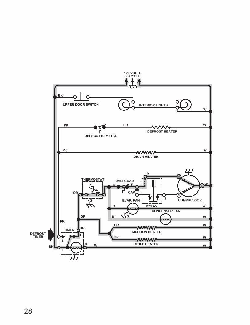
This wiring diagram is for a no-frost refrigerator. Note the defrost timer in the lower leftpart of the diagram. The defrost timer is closed to contact number 4 and the thermostat iscalling for cooling, and the compressor is running.
TRACE THE ACTIVE CIRCUITS BELOW WITH A WAVY LINE.
27
120 VOLTS60 CYCLE
BK
UPPER DOOR SWITCH INTERIOR LIGHTSW
PK
DEFROST BI-METAL
PK
PK
W
W
W
W
W
W
W
W
MULLION HEATER
STILE HEATER
CONDENSER FAN
EVAP. FAN
RELAY
DEFROST HEATER
DRAIN HEATER
BR
THERMOSTAT OVERLOADR
M
S
C
M
R
S
CAP.
COMPRESSOR
R
R
OR
OR
OR
OR
OR
BK
DEFROSTTIMER
1
23
4
W
TIMER
28
120 VOLTS60 CYCLE
BK
UPPER DOOR SWITCH INTERIOR LIGHTSW
PK
DEFROST BI-METAL
PK
PK
W
W
W
W
W
W
W
W
MULLION HEATER
STILE HEATER
CONDENSER FAN
EVAP. FAN
RELAY
DEFROST HEATER
DRAIN HEATER
BR
THERMOSTAT OVERLOADR
M
S
C
M
R
S
CAP.
COMPRESSOR
R
R
OR
OR
OR
OR
OR
BK
DEFROSTTIMER
1
23
4
W
TIMER

Note the defrost timer in this diagram. It has closed to contact number 2 and the refrigera-tor is now defrosting.
TRACE THE ACTIVE CIRCUITS BELOW WITH A WAVY LINE.
29
120 VOLTS60 CYCLE
BK
UPPER DOOR SWITCH INTERIOR LIGHTSW
PK
DEFROST BI-METAL
PK
PK
W
W
W
W
W
W
W
W
MULLION HEATER
STILE HEATER
CONDENSER FAN
EVAP. FAN
RELAY
DEFROST HEATER
DRAIN HEATER
BR
THERMOSTAT OVERLOADR
M
S
C
M
R
S
CAP.
COMPRESSOR
R
R
OR
OR
OR
OR
OR
BK
DEFROSTTIMER
1
23
4
W
TIMER

30
120 VOLTS60 CYCLE
BK
UPPER DOOR SWITCH INTERIOR LIGHTSW
PK
DEFROST BI-METAL
PK
PK
W
W
W
W
W
W
W
W
MULLION HEATER
STILE HEATER
CONDENSER FAN
EVAP. FAN
RELAY
DEFROST HEATER
DRAIN HEATER
BR
THERMOSTAT OVERLOADR
M
S
C
M
R
S
CAP.
COMPRESSOR
R
R
OR
OR
OR
OR
OR
BK
DEFROSTTIMER
1
23
4
W
TIMER

31
Let’s turn our attention to dishwasher wiring diagrams. In the dishwasher wiring diagrambelow let’s assume that the timer has advanced to a fill position and timer switches 2, 3, 5,and 22 are closed. The door is closed and the motor is running. We have closed the contactin the pushbutton selector switch and the push/pull switch for you.
TRACE THE ACTIVE CIRCUITS BELOW WITH A WAVY LINE.
BK G W
BK
W
W
W
W
DRIVEMOTOR
MOTOR STARTRELAY
BU-W
RUN 1
WASH 3
DRAIN 2
4
VBUBU
V
TIMER
3
2
1
5
4
Y
GY
BR BR
LBU
11
O-BK
6
19
LBU
O-BK
WET AGENT
DET. DISPENSERW-R
W-R
OVERFILL SW.FILL VALVE
BR-W
HEATER
W-R
W-R
PUSHBUTTON SWITCH
TIMER MOTOR
T-R
T-R
T-R
CABINET GROUND
THERMOSTAT
W-BK N.O.
W-BKW-BK
F
D
HR
P-BKP-BK
R
W-R
28
8
22
T-R
PUSH/PULLSWITCH
DOORSWITCH
T T

32
BK G W
BK
W
W
W
W
DRIVEMOTOR
MOTOR STARTRELAY
BU-W
RUN 1
WASH 3
DRAIN 2
4
VBUBU
V
TIMER
3
2
1
5
4
Y
GY
BR BR
LBU
11
O-BK
6
19
LBU
O-BK
WET AGENT
DET. DISPENSERW-R
W-R
OVERFILL SW.FILL VALVE
BR-W
HEATER
W-R
W-R
PUSHBUTTON SWITCH
TIMER MOTOR
T-R
T-R
T-R
CABINET GROUND
THERMOSTAT
W-BK N.O.
W-BKW-BK
F
D
HR
P-BKP-BK
R
W-R
28
8
22
T-R
PUSH/PULLSWITCH
DOORSWITCH
T T

33
Let’s trace the circuits for a “heat dry” cycle. During this cycle the drive motor stopsrunning and timer switches 1, 19, and 22 are closed. Once again, we have closed thecontact in the pushbutton selector switch and the push/pull switch for you.
TRACE THE ACTIVE CIRCUITS BELOW WITH A WAVY LINE.
BK G W
BK
W
W
W
W
DRIVEMOTOR
MOTOR STARTRELAY
BU-W
RUN 1
WASH 3
DRAIN 2
4
VBUBU
V
TIMER
3
2
1
5
4
Y
GY
BR BR
LBU
11
O-BK
6
19
LBU
O-BK
WET AGENT
DET. DISPENSERW-R
W-R
OVERFILL SW.FILL VALVE
BR-W
HEATER
W-R
W-R
PUSHBUTTON SWITCH
TIMER MOTOR
T-R
T-R
T-R
CABINET GROUND
THERMOSTAT
W-BK N.O.
W-BKW-BK
F
D
HR
P-BKP-BK
R
W-R
28
8
22
T-R
PUSH/PULLSWITCH
DOORSWITCH
T T

34
BK G W
BK
W
W
W
W
DRIVEMOTOR
MOTOR STARTRELAY
BU-W
RUN 1
WASH 3
DRAIN 2
4
VBUBU
V
TIMER
3
2
1
5
4
Y
GY
BR BR
LBU
11
O-BK
6
19
LBU
O-BK
WET AGENT
DET. DISPENSERW-R
W-R
OVERFILL SW.FILL VALVE
BR-W
HEATER
W-R
W-R
PUSHBUTTON SWITCH
TIMER MOTOR
T-R
T-R
T-R
CABINET GROUND
THERMOSTAT
W-BK N.O.
W-BKW-BK
F
D
HR
P-BKP-BK
R
W-R
28
8
22
T-R
PUSH/PULLSWITCH
DOORSWITCH
T T

35
Now we will focus on the microwave oven. The oven cavity light goes ON whenever thedoor is opened or the microwave oven is operating. This light goes OFF when the micro-wave oven is off.
The door is closed and the microwave oven is OFF.
TRACE THE POTENTIAL CIRCUITS BELOW WITH A WAVY LINE.
BK-W TF1 TF F F1
THERMAL FUSE FUSE 15 AMP
P
P1GY
GY
THERMALPROTECTOR
PRIMARYINTERLOCK SW.
R
(C) (N.O.)
R
R
R
MONITOR SW.
LIGHT SW.
(N.O.)
(N.C.)
(N.C.) (C)(C)
(C)
Y
OR
START SWITCH
COOK RELAY5 3
7 8
OR
Y
Y
Y
DEFROST SWITCH
CONTROL MODULE
OR-W
OR-W
Y
G
W
SELECTORRESISTOR10
4 3 2
1
MOTOR
TIMER/DEFROST SELECTOR
BU
W
W
W
YMOTOR
FAN MOTOR
OVEN LIGHT
(N.O.)
SECONDARYINTERLOCK SW.
OL OL1
BK BK
L1 N
120 VAC
G

36
You can see the potential circuit to the start switch.
BK-W TF1 TF F F1
THERMAL FUSE FUSE 15 AMP
P
P1GY
GY
THERMALPROTECTOR
PRIMARYINTERLOCK SW.
R
(C) (N.O.)
R
R
R
MONITOR SW.
LIGHT SW.
(N.O.)
(N.C.)
(N.C.) (C)(C)
(C)
Y
OR
START SWITCH
COOK RELAY5 3
7 8
OR
Y
Y
Y
DEFROST SWITCH
CONTROL MODULE
OR-W
OR-W
Y
G
W
SELECTORRESISTOR10
4 3 2
1
MOTOR
TIMER/DEFROST SELECTOR
BU
W
W
W
YMOTOR
FAN MOTOR
OVEN LIGHT
(N.O.)
SECONDARYINTERLOCK SW.
OL OL1
BK BK
L1 N
120 VAC
G

37
BK-W TF1 TF F F1
THERMAL FUSE FUSE 15 AMP
P
P1GY
GY
THERMALPROTECTOR
PRIMARYINTERLOCK SW.
R
(C) (N.O.)
R
R
R
MONITOR SW.
LIGHT SW.
(N.O.)
(N.C.)
(N.C.) (C)(C)
(C)
Y
OR
START SWITCH
COOK RELAY5 3
7 8
OR
Y
Y
Y
DEFROST SWITCH
CONTROL MODULE
OR-W
OR-W
Y
G
W
SELECTORRESISTOR10
4 3 2
1
MOTOR
TIMER/DEFROST SELECTOR
BU
W
W
W
YMOTOR
FAN MOTOR
OVEN LIGHT
(N.O.)
SECONDARYINTERLOCK SW.
OL OL1
BK BK
L1 N
120 VAC
G
Now, with the door is open and the microwave still OFF.
TRACE THE ACTIVE CIRCUITS BELOW WITH A WAVY LINE.

38
BK-W TF1 TF F F1
THERMAL FUSE FUSE 15 AMP
P
P1GY
GY
THERMALPROTECTOR
PRIMARYINTERLOCK SW.
R
(C) (N.O.)
R
R
R
MONITOR SW.
LIGHT SW.
(N.O.)
(N.C.)
(N.C.) (C)(C)
(C)
Y
OR
START SWITCH
COOK RELAY5 3
7 8
OR
Y
Y
Y
DEFROST SWITCH
CONTROL MODULE
OR-W
OR-W
Y
G
W
SELECTORRESISTOR10
4 3 2
1
MOTOR
TIMER/DEFROST SELECTOR
BU
W
W
W
YMOTOR
FAN MOTOR
OVEN LIGHT
(N.O.)
SECONDARYINTERLOCK SW.
OL OL1
BK BK
L1 N
120 VAC
G
39
BK-W TF1 TF F F1
THERMAL FUSE FUSE 15 AMP
P
P1GY
GY
THERMALPROTECTOR
PRIMARYINTERLOCK SW.
R
(C) (N.O.)
R
R
R
MONITOR SW.
LIGHT SW.
(N.O.)
(N.C.)
(N.C.) (C)(C)
(C)
Y
OR
START SWITCH
COOK RELAY5 3
7 8
OR
Y
Y
Y
DEFROST SWITCH
CONTROL MODULE
OR-W
OR-W
Y
G
W
SELECTORRESISTOR10
4 3 2
1
MOTOR
TIMER/DEFROST SELECTOR
BU
W
W
W
YMOTOR
FAN MOTOR
OVEN LIGHT
(N.O.)
SECONDARYINTERLOCK SW.
OL OL1
BK BK
L1 N
120 VAC
G
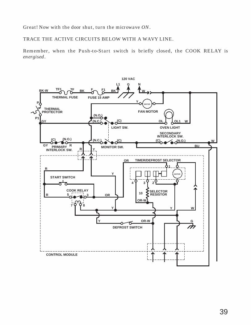
Great! Now with the door shut, turn the microwave ON.
TRACE THE ACTIVE CIRCUITS BELOW WITH A WAVY LINE.
Remember, when the Push-to-Start switch is briefly closed, the COOK RELAY isenergised.

40
BK-W TF1 TF F F1
THERMAL FUSE FUSE 15 AMP
P
P1GY
GY
THERMALPROTECTOR
PRIMARYINTERLOCK SW.
R
(C) (N.O.)
R
R
R
MONITOR SW.
LIGHT SW.
(N.O.)
(N.C.)
(N.C.) (C)(C)
(C)
Y
OR
START SWITCH
COOK RELAY5 3
7 8
OR
Y
Y
Y
DEFROST SWITCH
CONTROL MODULE
OR-W
OR-W
Y
G
W
SELECTORRESISTOR10
4 3 2
1
MOTOR
TIMER/DEFROST SELECTOR
BU
W
W
W
YMOTOR
FAN MOTOR
OVEN LIGHT
(N.O.)
SECONDARYINTERLOCK SW.
OL OL1
BK BK
L1 N
120 VAC
G

41
On this page we show symbols for a switch used on an air conditioner.
NOTE: The black dots within the switch indicate a junction, but when a switch function ischosen, all other dots except those on a horizontal line with the chosen function must beignored.
If the switch is set on HI FAN, the circuit through the switch is shown below.
If the switch is set on HI COOL, draw the circuit through the switch below.
If the switch is set on LO COOL, draw the circuit through the switch below.
LO COOL
HI COOL
HI FAN
OFF
L1 2 1 3
L2
SWITCH
LO COOL
HI COOL
HI FAN
OFF
L1 2 1 3
L2
SWITCH
LO COOL
HI COOL
HI FAN
OFF
L1 2 1 3
L2
SWITCH

42
HI COOL
LO COOL
LO COOL
HI COOL
HI FAN
OFF
L1 2 1 3
L2
SWITCH
LO COOL
HI COOL
HI FAN
OFF
L1 2 1 3
L2
SWITCH

43
Now that you know how to trace a circuit through the air conditioner switch, we want youto trace out a complete circuit.
TRACE A WAVY LINE BELOW THROUGH CIRCUITS WHICH ARE ACTIVE WHENTHE SWITCH IS ON THE HI FAN POSITION.
COMPRESSORBR
BK
Y
RUN CAPACITOR
BK
TEMP. CONTROL
MARKEDTERM. BR P
C
WH
L
FAN MOTORFAN MOTOR
RUN CAPACITOR
BL
OR
W
L2
L1 2 1 3
SWITCH
RIBBEDSERVICE CORD
LO COOL
HI COOL
HI FAN
OFF

44
NOTE THE CIRCUIT THROUGH THE FAN MOTOR. DID YOU GET IT RIGHT?
COMPRESSORBR
BK
Y
RUN CAPACITOR
BK
TEMP. CONTROL
MARKEDTERM. BR P
C
WH
L
FAN MOTORFAN MOTOR
RUN CAPACITOR
BL
OR
W
L2
L1 2 1 3
SWITCH
RIBBEDSERVICE CORD
LO COOL
HI COOL
HI FAN
OFF

45
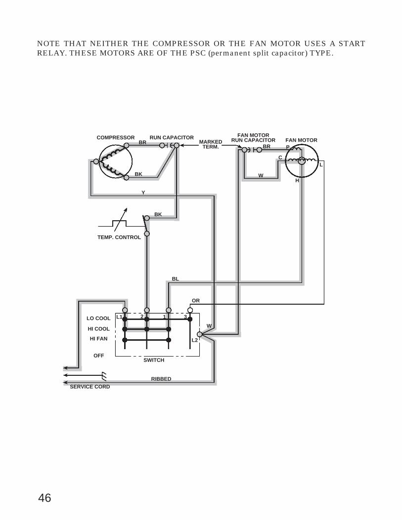
The fan circuit in the HI COOL and the HI FAN postions will be the same. Remember thatthis air conditioner temperature control switch (thermostat) closes on heat rise.
TRACE A WAVY LINE BELOW THROUGH THE ACTIVE CIRCUITS IN THE HI COOLSETTING.
COMPRESSORBR
BK
Y
RUN CAPACITOR
BK
TEMP. CONTROL
MARKEDTERM. BR P
C
WH
L
FAN MOTORFAN MOTOR
RUN CAPACITOR
BL
OR
W
L2
L1 2 1 3
SWITCH
RIBBEDSERVICE CORD
LO COOL
HI COOL
HI FAN
OFF
46
NOTE THAT NEITHER THE COMPRESSOR OR THE FAN MOTOR USES A STARTRELAY. THESE MOTORS ARE OF THE PSC (permanent split capacitor) TYPE.
COMPRESSORBR
BK
Y
RUN CAPACITOR
BK
TEMP. CONTROL
MARKEDTERM. BR P
C
WH
L
FAN MOTORFAN MOTOR
RUN CAPACITOR
BL
OR
W
L2
L1 2 1 3
SWITCH
RIBBEDSERVICE CORD
LO COOL
HI COOL
HI FAN
OFF

47
You knew we would want you to trace the LO COOL circuit, too!
TRACE A WAVY LINE BELOW THROUGH THE ACTIVE CIRCUITS IN THE LO COOLSETTING. WATCH CAREFULLY AS YOU TRACE THE CIRCUIT THROUGH THEFAN.
COMPRESSORBR
BK
Y
RUN CAPACITOR
BK
TEMP. CONTROL
MARKEDTERM. BR P
C
WH
L
FAN MOTORFAN MOTOR
RUN CAPACITOR
BL
OR
W
L2
L1 2 1 3
SWITCH
RIBBEDSERVICE CORD
LO COOL
HI COOL
HI FAN
OFF

48
Y
BK
COMPRESSORBR
BK
RUN CAPACITOR
TEMP. CONTROL
MARKEDTERM. BR P
C
WH
L
FAN MOTORFAN MOTOR
RUN CAPACITOR
BL
OR
W
L2
L1 2 1 3
SWITCH
RIBBEDSERVICE CORD
LO COOL
HI COOL
HI FAN
OFF

BLANK

BLANK