structure design of a sailing yacht hull by rules and …...structure design of a sailing yacht hull...
TRANSCRIPT

Structure design of a sailing yacht hull by rules and
direct method
Ivan Klarić
Master Thesis
presented in partial fulfillment
of the requirements for the double degree:
“Advanced Master in Naval Architecture” conferred by University of Liege
“Master of Sciences in Applied Mechanics, specialization in Hydrodynamics,
Energetics and Propulsion” conferred by Ecole Centrale de Nantes
developed at University of Genoa
in framework of the
“EMSHIP”
Erasmus Mondus Master Course
in “Integrated Advanced Ship Design”
Supervisor: Prof. Dario Boote, University de Genoa
Reviewer: Dr. Zbigniew Sekulski, West Pomeranian University of Technology, Szczecin
Genoa, February 2012


Declaration of Authorship
I declare that this thesis and the work presented in it are my own and have been generated by
me as the result of my own original research.
Where I have consulted the published work of others, this is always clearly attributed.
Where I have quoted from the work of others, the source is always given. With the exception
of such quotations, this thesis is entirely my own work.
I have acknowledged all main sources of help.
This thesis contains no material that has been submitted previously, in whole or in part, for
the award of any other academic degree or diploma.
I cede copyright of the thesis in favour of the University of Genoa, University of Liege and
Ecole Centrale de Nantes.
Date: Signature:
17.1.2012
Ivan Klarić

Table of Contents
ABSTRACT ............................................................................................................................... 1
1. INTRODUCTION .............................................................................................................. 2
2. SCANTLING ...................................................................................................................... 7
2.1 Arbitrary Plate Scantling .......................................................................................... 11
2.2 Deck Structure Scantling .......................................................................................... 14
2.3 Side Structure Scantling ........................................................................................... 20
2.4 Bottom Structure Scantling ...................................................................................... 23
3. ALUMINUM .................................................................................................................... 32
3.1. Types of Aluminum ................................................................................................. 32
3.2. Advantages of Aluminum: ....................................................................................... 35
3.3. Disadvantages of Aluminum .................................................................................... 37
4. FINITE ELEMENTH METHOD ..................................................................................... 38
5. FINITE ELEMENTH METHOD ANALYSIS................................................................. 41
5.1. Main Mast Base Foundation .................................................................................... 42
5.1.1. Comparison between first and second load case ................................................ 45
5.1.2. Comparison between shell and solid element .................................................... 46
5.1.3. Linear analysis .................................................................................................... 51
5.1.4. Solution of the problem, for existing structure .................................................. 56
5.1.6. Influence of the mesh on the results .................................................................. 60
5.2. Keel – Hull Structure Connection ............................................................................ 63
5.2.1. Model of the keel – structure connection ........................................................... 65
5.2.2. Loads and boundary conditions .......................................................................... 67
5.2.3. Total deformation of the keel by direct method ................................................. 73
5.2.4. Total deformation of the keel and the structure ................................................. 75
5.2.5. Von-Mises stress ................................................................................................ 79
5.2.6. Normal stress ...................................................................................................... 82
5.2.7. Shear stress ......................................................................................................... 84
CONCLUSION ........................................................................................................................ 87
ACKNOWLEDGEMENTS ..................................................................................................... 89
REFERENCES ......................................................................................................................... 90

Table of figures
Figure 1. Word market of sailing yacht over 45 m in 2010 ....................................................... 4
Figure 2. Maltese Falcon sailing yacht, built in Perini Navi at 2006 ......................................... 4
Figure 3. 58 m sailing yacht from Perini Navi ........................................................................... 5
Figure 4. Sailing yacht profile at centreline [3].......................................................................... 9
Figure 5. Transverse section of sailing yacht [3] ..................................................................... 10
Figure 6. Sections of the main frame at which the scantling will be performed ...................... 11
Figure 7. Arbitrary chosen plate ............................................................................................... 11
Figure 8. Profiles and dimensions for the arbitrary chosen plate ............................................. 14
Figure 9. Section modulus for flat bar profile .......................................................................... 18
Figure 10. Section modulus for T profile ................................................................................. 18
Figure 11. Deck structure ......................................................................................................... 19
Figure 12. Side structure .......................................................................................................... 22
Figure 13. Profile at centerline ................................................................................................. 24
Figure 14. Transverse section ................................................................................................... 24
Figure 15. Bottom structure ..................................................................................................... 29
Figure 16. Details of the bottom structure ................................................................................ 29
Figure 17. Main frame of the sailing yacht .............................................................................. 31
Figure 18. Methodology of FEM [5] ........................................................................................ 38
Figure 19. Elements types in FEM [5] ..................................................................................... 38
Figure 20. Approach to FEM analysis [5] ................................................................................ 39
Figure 21. Sailing yacht 2193 series [6] ................................................................................... 41
Figure 22. Parts of ship hull structure on which it were performed FEM analysis .................. 42
Figure 23. Parts of main mast base construction ...................................................................... 43
Figure 24. Dimension of the main mast base foundation ......................................................... 43
Figure 25. Visualization of the first and second load case of main mast base foundation....... 44
Figure 26. Connection of the mast with the structure for the first load case............................ 44
Figure 27. Connection of the mast with the structure for the second load case ....................... 44
Figure 28. Final mesh of the model .......................................................................................... 45
Figure 29. First step of calculations ......................................................................................... 45
Figure 30. Total deformation for the first and second load case .............................................. 46
Figure 31. Normal stress in the top plate for the second load case .......................................... 46
Figure 32. Shell 181 geometry ................................................................................................. 47

Figure 33. Solid 186 geometry ................................................................................................. 47
Figure 34. Second step of calculations ..................................................................................... 48
Figure 35. Shell - left, solid - right ........................................................................................... 49
Figure 36. Mesh of shell – left, solid – right ............................................................................ 49
Figure 37. Total deformation, shell – left, solid – right ........................................................... 49
Figure 38. Von-Mises, shell – left, solid – right ...................................................................... 49
Figure 39. Normal stress, shell – left, solid – right .................................................................. 50
Figure 40. Shear stress, shell – left, solid – right ..................................................................... 50
Figure 41. Total error, shell – left, solid – right ....................................................................... 50
Figure 42. Top view, shell – left, solid - right .......................................................................... 51
Figure 43. Model with shell elements – bottom view .............................................................. 51
Figure 44. Stress – strain relation for linear analysis ............................................................... 51
Figure 45. Third step of calculations ........................................................................................ 52
Figure 46. Total deformation and Von-Mises, linear analysis ................................................. 52
Figure 47. Normal and shear stress, linear analysis ................................................................. 52
Figure 48 Stress – strain relation for nonlinear analysis .......................................................... 53
Figure 49. Fourth step of calculations ...................................................................................... 53
Figure 50. Nonlinear analysis, convergence of the results ....................................................... 54
Figure 51. Total deformation and Von-Mises stress, nonlinear analysis ................................. 54
Figure 52. Normal and shear stress, nonlinear analysis ........................................................... 55
Figure 53. Places the where stresses are bigger than yielding (215 MPa), Von-Mises – left,
Normal stress - right ................................................................................................................. 55
Figure 54. Total deformation of the structure with additional bracket in different positions .. 56
Figure 55. Von-Mises stress of the structure with additional bracket in different positions ... 56
Figure 56. Normal stress of the structure with additional bracket in different positions ......... 56
Figure 57. Connection of main mast base foundation with ship structure ............................... 57
Figure 58. Total deformation of the ship structure ................................................................... 57
Figure 59. Von-Mises stress of the ship structure .................................................................... 57
Figure 60. Places where Von-Mises stress is bigger than 210 MPa ........................................ 58
Figure 61. Normal stress of the ship structure ......................................................................... 58
Figure 62. Shear stress of the ship structure ............................................................................. 58
Figure 63. Total deformation, new construction ...................................................................... 59
Figure 64. Von-Mises stress, new construction ....................................................................... 59

Figure 65. Normal stresses, new construction .......................................................................... 59
Figure 66. Different mesh sizes, 50 mm, 30 mm and 10 mm elements ................................... 60
Figure 67. Total deformation for the 50 mm, 30 mm and 10 mm element sizes ..................... 60
Figure 68. Number of elements vs mesh size ........................................................................... 61
Figure 69. CPU time vs mesh size ........................................................................................... 61
Figure 70. CPU time vs number of elements ........................................................................... 61
Figure 71. Structural error vs mesh size ................................................................................... 62
Figure 72. 2-D drawing of the keel from Perini-Navi (left), 3-D model of the keel made in
SolidWorks (right) .................................................................................................................... 66
Figure 73. 3-D model of the keel structure .............................................................................. 66
Figure 74. 2-D drawing of the structure from Perini-Navi (left), 3-D model of the structure
made in ANSYS (right) ............................................................................................................ 67
Figure 75. Model of the ship structure ..................................................................................... 67
Figure 76. Total mass that acts in cetner of gravity ................................................................. 68
Figure 77. Boundary conditions and centre of gravity ............................................................. 68
Figure 78. Boundary conditions, red – displacement supports, blue – compression only
support (view from both sides) ................................................................................................. 69
Figure 79. Difference between fixed and compression only support ....................................... 70
Figure 80. Standard Earth Gravity, properties of ANSYS ....................................................... 70
Figure 81. Example of the bonded connection in ANSYS ...................................................... 71
Figure 82. Loads and boundary condition for the structure ..................................................... 73
Figure 83. Section of the keel from SolidWorks (up) and Perini Navi (down) ....................... 74
Figure 84. Console with force acting at end of the console ..................................................... 74
Figure 85. Total deformation of the keel structure ................................................................... 76
Figure 86. Deformation at position of the centre of gravity ..................................................... 76
Figure 87. Total deformation of the yacht structure ................................................................. 76
Figure 88. Values of stress at connection of the keel structure with keel head ....................... 77
Figure 89. Structural error of the keel ...................................................................................... 78
Figure 90. Structural error of the yacht structure ..................................................................... 78
Figure 91. Von-Mises stress of the keel structure .................................................................... 79
Figure 92. View of the connection swing keel head with structural blade for Von-Mises stress
.................................................................................................................................................. 79
Figure 93. Places where Von-Mises stresses are bigger than 105 MPa ................................... 80
Figure 94. Comparison of the results with boundary conditions ............................................. 80

Figure 95. Von-Mises stress for the yacht structure ................................................................. 81
Figure 96. Places where stresses are bigger than 105 MPa on the yacht structure .................. 81
Figure 97. Normal stress of the keel structure ......................................................................... 82
Figure 98. View of the connection swing keel head with structural blade for Normal stress .. 82
Figure 99. Places where Normal stresses are bigger than 105 MPa ........................................ 83
Figure 100. Normal stress for the yacht structure .................................................................... 83
Figure 101. Shear stress of the keel structure ........................................................................... 84
Figure 102. View of the connection swing keel head with structural blade for shear stress ... 84
Figure 103. Places where Shear stresses are bigger than 105 MPa .......................................... 85
Figure 104. Shear stress for the yacht structure ....................................................................... 85
List of major label
Symbol Meaning First use
OAL length overall
WLL length of water line
L scantling length (1.1)
B breadth
D molded depth
d draft for scantlings
∆ displacement
t thickness of plates / stiffeners (1.2)
s frame spacing
c correction factor
k aspect ratio coefficient
σa design stress
SM section modulus (1.3)
CF design head for Internals factor (1.4)
A area of profile (1.5)
b breadth of profile (1.5)
h height of profile (1.5)
zg center of gravity for profile (1.6)
I moment of inertia (1.7)
CG centre of gravity (5.1)
δ deflection (5.2)
F force (5.2)
E modul of elasticity (5.2)
σ stress (5.3)
M moment (5.3)

Structure design of a sailing yacht hull by Rules and direct methods
1
“EMSHIP” Erasmus Mundus Master Course, period of study September 2010 - February 2012
ABSTRACT
The thesis was done at Perini-Navi shipyard, Viareggio and at University of Genoa, Italy.
Thesis is divided in two parts. Fist part is scantling of the main frame for a sailing boat and in second
part it has been performed the finite element analysis (FEM) of the structure. Scantling (main
dimensions), for the yacht of 58 m in length has been done according to the American Bureau of
Shipping (ABS) rules, Guide for Building and Classing Offshore Racing Yachts (ORY). The purpose
of the scantling is to become familiar with the structure design of the sailing yacht and also to
understand how to apply the rules. Material that shipyard is using for the construction of the sailing
yachts is aluminium. Because of aluminium nature and big use in shipbuilding industry, one chapter is
dedicated for this material with all properties, alloys, advantages and disadvantages.
The scope of the work was to perform the FEM analysis for the specific parts of ship hull. As
shipyard already had FEM analysis of the entire hull, in agreement with shipyard and university, in
this thesis were investigated main mast base foundation and connection of the keel with the structure
of the yacht.
During the building of the hull, main mast for sails was changed and main mast base
foundation that was already built does not satisfy for new loads coming from the main mast. Because
of that, it is necessary to verify this structure on new loads. Also, purpose of this first model was to
become familiar with the software features. So it was analysed difference between shell and solid
elements, influence of mesh on the results, linear and nonlinear analysis. Nonlinear analysis has been
done because the structure was exceeding yielding stress of 215 MPa for aluminium. After, when all
analysis has been performed, it was necessary to propose the solution to shipyard; how to solve the
problem on existing structure and how to adapt the new structure for this kind of loads.
Second model is connection of the keel with the structure of the yacht. Keel is 8 m long and
total mass of the keel; aluminium structure with the lead inside is 65 tons, and according to the rules,
keel must withstand its own mass acting in centre of gravity. To satisfy the rules criteria and to prove
direct method that have been used for the calculation of the keel deflection and stresses, FEM analysis
of the keel – structure connection has been done. The analysis expected to show that deflection of the
keel is 41 mm and the analysis showed that deflection is 74 mm at centre of gravity and more than 200
mm at the end of the keel. After, it was necessary to verify the stresses and deflection on the hull
structure where the keel is connected. Connection between structure and keel is with the pin. The
models were made separately, because of the complexity to simulate pin connection and the forces
measured by probes on the keel are transmitted to the structure. But analysis showed that deflection is
quite small at hull structure and that structure is very well design.

Ivan Klarić
2 Master thesis developed at the Università degli Studi di Genova, Italy
1. INTRODUCTION
A yacht is recreational boat or ship. The first appearances were in 17th
century when
the Dutch navy built yachts to catch and pursuit pirates around and into the shallow waters of
the Netherland. Because of that, the name yacht has the roots in Dutch language and the word
“jagen”, meaning to hunt or chase. The word Yacht usually refers to a small, fast craft for the
purpose of small voyages and short crossing. In meanwhile they were also used for non-
military governmental roles such as customs duties and delivering pilots to the ships. The later
use was for the private and pleasure purpose, the first yachts were attracted the attention of
rich Dutch merchants. By the start of the 17th
century yacht came in two broad categories,
speel-jachts for sport and oorlog-jachts for naval duties. [1]
The delight of yachting for pleasure was developing very fast and also the trend cross
the channel to the England. One of the first Englishmen who were sailing with yachts was
Charles II. During the 17th
century, yachting began to flourish across Europe. All of kinds
were commissioned as yachts to the rich and powerful, from tiny open boats to small frigates.
Yachts were instrumental in discovering new lands and defending vital waterways. They
served both as pleasure craft and as working ships, carrying people and messages swiftly and
comfortably to the shore.
Originally yachts were built in wood and in construction quite similar to what was
customary in the normal shipbuilding of that time. The hull was single (massive) planking
connected to closely spaced wooden frames. The frames were connected to wooden floors and
those to the bottom planking. In the early days many yachts still had flat or slightly curved
bottom. At the upper side the frames were connected to the deck beams on which the deck
planking was laid. Longitudinal stringers were mostly absent. Later when yachts got keels the
construction changed. The sections became rather more V shaped asking for different
construction techniques. The stem beam, the keel beam and the stern beam were introduced,
which functioned also as longitudinal stiffeners, to which the frames were connected, which
in turn were connected by the floors. The difficulties and weaknesses in the available
connecting techniques of that time however posed a serious limit on the achievable overall
strength and in more in particular the overall rigidity of the yacht hull structure. All wooden
construction was only to return in yacht building after the 1970’s, when new and serious
bonding techniques became available, such as the epoxy resins, together with new wood
laminating techniques. So in the 1930’s the new “composite” construction technique came
into force, in which the keel, stem, stern, frames, beams and floors were all constructed in

Structure design of a sailing yacht hull by Rules and direct methods
3
“EMSHIP” Erasmus Mundus Master Course, period of study September 2010 - February 2012
steel (and bolted or riveted, later welded together) to which the still wooden hull and deck
planking was connected. This was a big improvement and however still rather heavy. Still
later the completely steel hull came into play in which now in the composite construction also
the wooden hull planking and later also the wooden deck planking was replaced by steel and
all were riveted or welded together. This yields a sound and stiff construction for the hull.
This construction technique, using either steel or aluminium, lasts till today and is mostly
favoured for the bigger yachts or for yachts with high demands on resistance against external
local loads, such as yachts designed for use on long ocean voyages or in the arctic regions [2].
The Perini Navi Group is operative in the super yacht sector under two specific brand
names: Perini Navi (sail yacht division) and Picchiotti (motor yacht division). The Group was
founded in 1983 as Perini Navi and produced sailing yachts. From 1983 until nowadays
Perini-Navi built more than 50 sailing yachts and has several others in production. Today the
Perini Navi Group is operative in five specific market sectors:
• Large sailing yachts that range from 40 to 60 metres
• Large sailing yachts over 60 meters and custom projects
• A Racing Line of sailing yachts
• A Fast Cruising line of sailing yachts
• Picchiotti motor yachts
The Perini Navi group is composed of four companies bought over time and acquired
with the objective of maximizing production capacity and entering new market segments. And
companies are located in:
• Perini Navi, Viareggio – Italy
• Cantiere Picchiotti, La Spezia – Italy
• Perini Istanbul, Yildiz – Turkey
• Perini Navi USA, Newport, Rhode Island - USA
All the sail handling systems are developed and constructed in the shipyard, as are the
masts and the rigging. Exclusive Perini Navi software is installed on board and monitors their
yachts while under sail automatically transmitting data to the construction office.

Ivan Klarić
4 Master thesis developed at the Università degli Studi di Genova, Italy
Figure 1. Word market of sailing yacht over 45 m in 2010
The five biggest sailing yachts in the world:
Name Launch LOA Gross tonnage Shipyard
Eos 2006 92.9 m 1500 Lurssen
Athena 2004 90 m 1123 Royal Huisman
Maltese Falcon 2006 88 m 1110 Perini Navi
Mirabella V 2004 75.2 m 1004 Vosper Thornycroft
Phocea 1976 75.1 m 530 DCAN
Figure 2. Maltese Falcon sailing yacht, built in Perini Navi at 2006
This brief introduction was to obtain basic information about history of yacht and
Perini Navi Group. Further in the thesis scantling will be done according to the ABS rules.
Scantling will be done for the main frame, of 58 m sailing yacht. From the scantling it is
necessary to understand the rules and how to apply them.

Structure design of a sailing yacht hull by Rules and direct methods
5
“EMSHIP” Erasmus Mundus Master Course, period of study September 2010 - February 2012
Figure 3. 58 m sailing yacht from Perini Navi
After scantling, one chapter will be for a material, the aluminium, because this
material is very important material in shipbuilding and it has lot of advantages and properties
that will be mention here.
At the end of the thesis finite element analysis will be done. It will not be performed
analysis of the entire hull. Because shipyard already has that analysis, so in agreement with
university and shipyard it was decided to simulate keel – structure connection. That part of a
yacht has a big importance in sailing yacht. Just to imagine the complicity of this model it is
enough to say that mass of the keel is 65 tons and the length is 7990 mm, type of the keel is
the swing keel and connection with the structure is with the pin. As classification society is

Ivan Klarić
6 Master thesis developed at the Università degli Studi di Genova, Italy
demanding this kind of calculation, it is necessary for the shipyard to perform such calculation
and present results to the classification society. Model will be done in SolidWorks and FEM
analysis will be done in ANSYS Workbench. However, before this project will be start to
model and analyse, from great importance is to become familiar with the ANSYS features, to
be able to set up the true model of the keel – structure connection. And because of that, first in
beginning of the project, one small and simply model will be done. It will be the model of
main mast base foundation. That model is chosen, because during the construction of the
sailing yacht, mast design was changed and the main mast base foundation didn’t satisfy
anymore the new loads. So through this quite simple model, it was necessary to learn the
software, verify its feature and the structure on new type of loads.
Structure design of a sailing yacht hull by Rules and direct methods
7
“EMSHIP” Erasmus Mundus Master Course, period of study September 2010 - February 2012
2. SCANTLING
To determining the scantlings there are two standard methods. The first method and by
far the oldest is rule-of-thumb and the second is engineering analysis. Rule-of-thumb is the
most reliable and formalized scantling rules. These rules are based on engineering analysis
cross checked against a database of successful vessels. The results are then condensed and
simplified for quick application using easily determined factors. Such rules establish the
required construction materials and dimensions based on a few easily obtainable numbers,
such length overall, displacement and boat speed. Scantling rules have been one of the
principal methods of specifying boat construction for well over a hundred years. They have
been used by classification societies, such as the American Bureau of Shipping, Lloyds and
others, by many of the finest designers and builders. And because of their ease of use, as
compared with detailed engineering analysis, many builders and designers prefer to work with
scantling rules. It is important to keep in mind that scantling rules work only for the specific
type and size of boat intended by the initial rulemaker.
Scantling will be done according to ABS1 rules. Guide for Building and Classing
Offshore Racing Yachts, 1994. The ABS is a classification society with a mission to promote
the security of life, property and the natural environment, primarily through the development
and verification of standards for the design, construction and operational maintenance of
marine-related facilities. Classification society is non-governmental organization that
establishes and maintains technical standards for the construction and operation of ships and
offshore structures. The society will validate that construction is according to these standards
and carry out regular surveys in service to ensure compliance with the standards.
ABS was first charted in the state of New York in 1862, to certify ships captains. It
has been involved in the development and improvement of safety standards. Born out of a
need for industry self-regulation, ABS published its first technical standards, Rules for Survey
and Classing Wooden Vessels, in 1870. When the era of wooden ships gave way to iron, ABS
established standards for these structures, published as Rules for Survey and Classing of Iron
Vessels. And after when iron gave way to steel, ABS published Rules for Building and
Classing Steel Vessels were established and published in 1890. These Steel Vessel Rules
continue to be revised and published annually.
1 ABS – American Bureau of Shipping
Ivan Klarić
8 Master thesis developed at the Università degli Studi di Genova, Italy
ABS today has more than 3,300 employees worldwide and is broadly divided in two
groups; Engineering review and Surveying. Engineers work in office buildings worldwide, the
headquarters of ABS American Division is located in Houston, Texas, USA, for Europe
headquarters is in London and headquarters for Asia Pacific region is located in Singapore.
For the sailing yacht rules provide all the main aspects of sailing yacht design, those
are: materials, details and fastenings, plating, internals, rudders and keels. The only areas on
which no indications are provided are for the mast and rigging. Where the hull scantlings are
concerned, the Rules in section 7 provides formulas and tables for the thickness calculation of
plating; aluminium, steel, fibre reinforced plastic (both single skin and sandwich) and wood
are considered. The same approach is assumed for the scantling of internal reinforcements.
For all those aspects that are not included in the Offshore Racing Yacht Guide, reference
should be made to the “Guide for Building and Classing of Motor Pleasure Yachts” (ABS,
2000) for displacement and semi-planing yachts. Designers of large sailing yachts capable of
sustaining highspeeds (in the planing regime) are referred to the “Guide for Building and
Classing High Speed Craft” (ABS, 2001) for appropriate hull plating and internal structure
scantlings.
Sec. 2 – 2.1:
Scantling length is given by the following equation:
2
OA WLL LL
+= (1.1)
58.6 m - is the overall length of the hullOAL =
50.43 mWLL =
54.52 mL =
Sec. 2 – 2.2:
11.4 mB = - is the greatest molded breadth, excluding appendages
Sec. 2 – 2.5:
3.85 mD = - is the molded depth at side in meters, measured vertically from the
bottom of the canoe hull at centerline to the top of main weather deck at side.
Sec. 2 – 2.7:
2.15 md = - draft for scantlings, is the maximum distance in meters or feet measured
vertically from the bottom of the canoe hull at its lowest point at centerline to the maximum
estimated displacement waterline.

Structure design of a sailing yacht hull by Rules and direct methods
9
“EMSHIP” Erasmus Mundus Master Course, period of study September 2010 - February 2012
Sec. 2 – 2.15.1:
Steel and aluminum, boat is build from aluminum and more about that material will be
in next chapter. Here just some main characteristic of used material are shown.
Alloy: 5083
Temper: H321
Thickness: Up to the 38 mm
Minimum ultimate tensile strength, welded condition: 275 N/mm2
Minimum yield strength, unwelded condition: 215 N/mm2
Main dimension of the sailing yacht:
58.6 mOAL =
11.4 mB =
3.85 mD =
2.15 mT =
15.5 knv =
540 t∆ =
Figure 4. Sailing yacht profile at centreline [3]
Ivan Klarić
10 Master thesis developed at the Università degli Studi di Genova, Italy
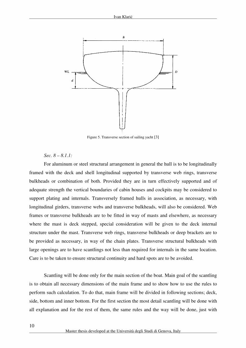
Figure 5. Transverse section of sailing yacht [3]
Sec. 8 – 8.1.1:
For aluminum or steel structural arrangement in general the hull is to be longitudinally
framed with the deck and shell longitudinal supported by transverse web rings, transverse
bulkheads or combination of both. Provided they are in turn effectively supported and of
adequate strength the vertical boundaries of cabin houses and cockpits may be considered to
support plating and internals. Transversely framed hulls in association, as necessary, with
longitudinal girders, transverse webs and transverse bulkheads, will also be considered. Web
frames or transverse bulkheads are to be fitted in way of masts and elsewhere, as necessary
where the mast is deck stepped, special consideration will be given to the deck internal
structure under the mast. Transverse web rings, transverse bulkheads or deep brackets are to
be provided as necessary, in way of the chain plates. Transverse structural bulkheads with
large openings are to have scantlings not less than required for internals in the same location.
Care is to be taken to ensure structural continuity and hard spots are to be avoided.
Scantling will be done only for the main section of the boat. Main goal of the scantling
is to obtain all necessary dimensions of the main frame and to show how to use the rules to
perform such calculation. To do that, main frame will be divided in following sections; deck,
side, bottom and inner bottom. For the first section the most detail scantling will be done with
all explanation and for the rest of them, the same rules and the way will be done, just with
Structure design of a sailing yacht hull by Rules and direct methods
11
“EMSHIP” Erasmus Mundus Master Course, period of study September 2010 - February 2012
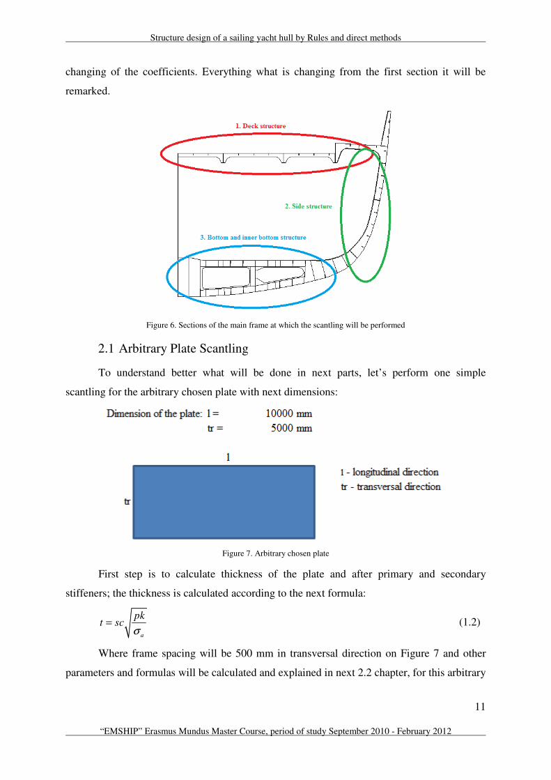
changing of the coefficients. Everything what is changing from the first section it will be
remarked.
Figure 6. Sections of the main frame at which the scantling will be performed
2.1 Arbitrary Plate Scantling
To understand better what will be done in next parts, let’s perform one simple
scantling for the arbitrary chosen plate with next dimensions:
Figure 7. Arbitrary chosen plate
First step is to calculate thickness of the plate and after primary and secondary
stiffeners; the thickness is calculated according to the next formula:
a
pkt sc
σ= (1.2)
Where frame spacing will be 500 mm in transversal direction on Figure 7 and other
parameters and formulas will be calculated and explained in next 2.2 chapter, for this arbitrary

Ivan Klarić
12 Master thesis developed at the Università degli Studi di Genova, Italy
plate is just important to understand the procedure how to perform the scantling. Position of
the plate is chosen to be at h = 5 m.
8.05 mmt =
And after all other requirements are met the thickness for aluminum in general, is to be
not less than s/100 or 2.5 mm whichever is greater. According to this:
5 mmt =
Chosen thickness of the plate will be 9 mm.
Calculation for the section modulus of the stiffeners is according to the next formula:
2
k
a
ChslSM SM
σ= + (1.3)
It is important to understand that procedure is starting from the smallest secondary
longitudinal and the smallest plate of 500 x 625 mm dimensions. The secondary longitudinals
are transferring the stresses to the secondary transversals. So the length of them will be
between two transversals. Secondary transversal are transferring the stresses to primary
longitudinals and primary longitudinals to primary transversals. It is necessary to follow this
order to be sure in spacing and length of each member, because section modulus is
proportional with spacing and with length on square.
First iteration:
Let us suppose the plate will contain secondary longitudinal and transversals and
edges will be supported by primary longitudinal and transversals.
Table 1. Spacing and length of the stiffeners for the first iteration
From calculation for section modulus next is obtained:
Table 2. Section modulus and profiles of stiffeners for the first iteration
spacing [mm] length [mm] number of elements
500 625 9
625 5000 15
5000 10000 2
10000 5000 2
Secondary longitudinals
Secondary transversals
Primary longitudinals
Primary transversals
Stiffener
Profile Web [mm] Flange [mm] SMrequired SMprofile
FB 90 x 8 6,47 10,8
T profile 500 x 12 120 x 12 517,97 671
16575Too big dimensions
Stiffener
Secondary longitudinals
Secondary transversals
Primary longitudinals
Primary transversals
Structure design of a sailing yacht hull by Rules and direct methods
13
“EMSHIP” Erasmus Mundus Master Course, period of study September 2010 - February 2012
From obtained results, primary longitudinal will be too big dimensions compared with
the plate, so it is necessary to reduce the spacing.
Second iteration:
Now we reduce the spacing of primary longitudinal and by that the length of the
secondary and primary transversals is also reduced.
Table 3. Spacing and length of the stiffeners for the second iteration
Now next profiles are obtained:
Table 4. Section modulus and profiles of stiffeners for the second iteration
Still the section modulus is big so now it is necessary to reduce the length of the
primary longitudinals by adding more primary transversals.
Third iteration:
For the third iteration spacing of the primary transversal is reduced and with that
length if the primary longitudinal is reduced too.
Table 5. Spacing and length of the stiffeners for the third iteration
The profiles are:
Table 6. Section modulus and profiles of stiffeners for the third iteration
spacing [mm] length [mm] number of elements
500 625 8
625 2500 15
2500 10000 3
10000 2500 2
Stiffener
Secondary longitudinals
Secondary transversals
Primary longitudinals
Primary transversals
Profile Web [mm] Flange [mm] SMrequired SMprofile
FB 90 x 8 6,47 10,8
T profile 250 x 10 100 x 12 129,49 161
8287,5Too big dimensions
Stiffener
Secondary longitudinals
Secondary transversals
Primary longitudinals
Primary transversals
spacing [mm] length [mm] number of elements
500 625 8
625 2500 12
2500 2500 3
2500 2500 5
Stiffener
Secondary longitudinals
Secondary transversals
Primary longitudinals
Primary transversals
Profile Web [mm] Flange [mm] SMrequired SMprofile
FB 90 x 8 6,47 10,8
T profile 250 x 10 100 x 12 129,49 161
T profile 450 x12 120 x 12 517,97 671
T profile 450 x 12 120 x 12 517,97 671
Stiffener
Secondary longitudinals
Secondary transversals
Primary longitudinals
Primary transversals
Ivan Klarić
14 Master thesis developed at the Università degli Studi di Genova, Italy
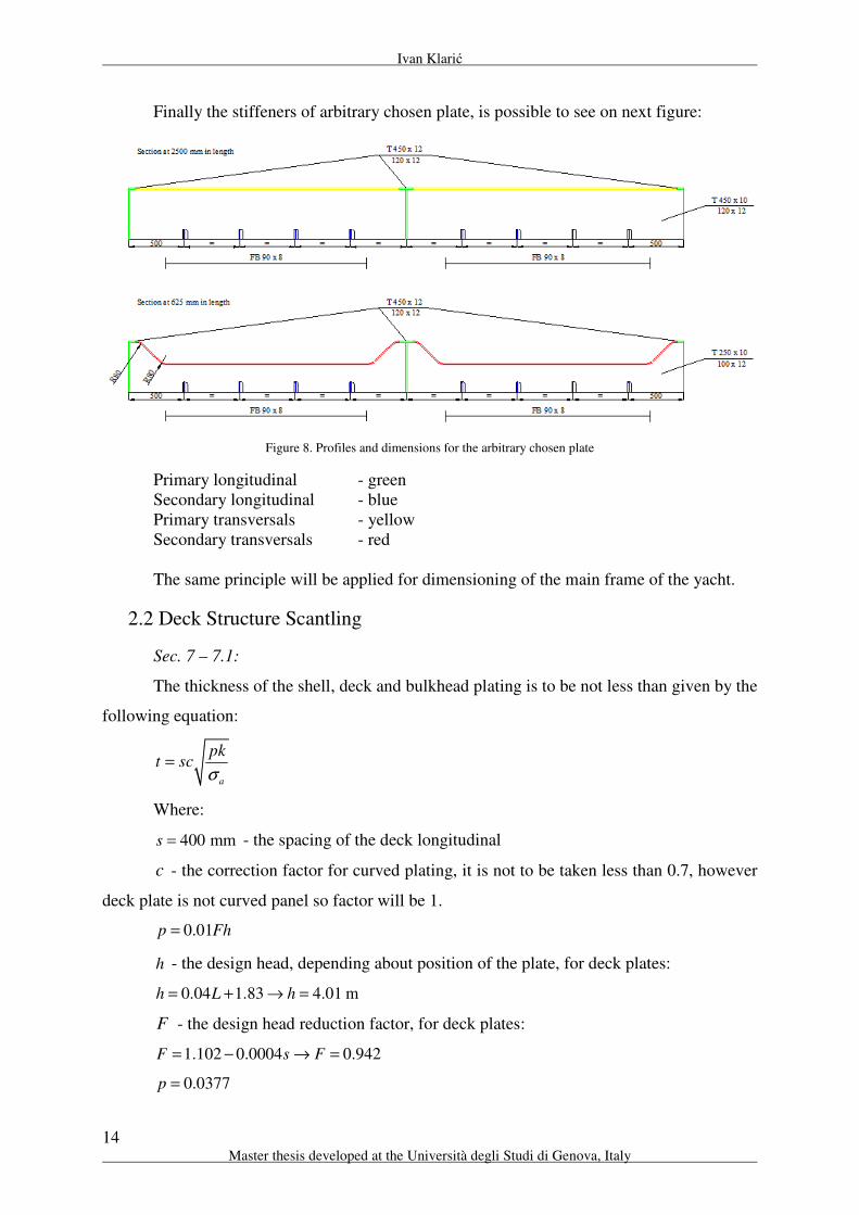
Finally the stiffeners of arbitrary chosen plate, is possible to see on next figure:
Figure 8. Profiles and dimensions for the arbitrary chosen plate
Primary longitudinal - green
Secondary longitudinal - blue
Primary transversals - yellow
Secondary transversals - red
The same principle will be applied for dimensioning of the main frame of the yacht.
2.2 Deck Structure Scantling
Sec. 7 – 7.1:
The thickness of the shell, deck and bulkhead plating is to be not less than given by the
following equation:
a
pkt sc
σ=
Where:
400 mms = - the spacing of the deck longitudinal
c - the correction factor for curved plating, it is not to be taken less than 0.7, however
deck plate is not curved panel so factor will be 1.
0.01p Fh=
h - the design head, depending about position of the plate, for deck plates:
0.04 1.83 4.01 mh L h= + → =
F - the design head reduction factor, for deck plates:
1.102 0.0004 0.942F s F= − → =
0.0377p =

Structure design of a sailing yacht hull by Rules and direct methods
15
“EMSHIP” Erasmus Mundus Master Course, period of study September 2010 - February 2012
k - the coefficient varying with the plate panel aspect ratio, according to the equation:
( )( )6
0.5
1 0.623 /k
s l=
+
690 mml = - distance between two frames, this distance was chosen in agreement
with the coordinator from Perini Navi
0.488k =
aσ - the design stress, for shell and deck it should be 0.6 of minimum ultimate tensile
strength. For aluminum, the minimum ultimate tensile strength is for the welded condition,
20.6 275 165 N/mma
σ = ⋅ =
Thickness of the deck plate is:
4.22 mmt =
After all other requirements are met the thickness for aluminum in general, is to be not
less than s/100 or 2.5 mm whichever is greater. According to this:
4 mmt =
Chosen thickness of the deck plate will be: 5 mmt =
Position of deck will be at 5800 mm from the center line.
Now it will be calculated section modulus of the stiffeners and according to section
modulus stiffener will be chosen. There are two approaches to do this calculation. First, it is
possible to start from dimensioning of the primary longitudinals, than transversals and for the
last secondary longitudinals, or it is possible to go reverse, from the secondary longitudinals
to the primary longitudinals. The scantling here will be done according to the second
possibility; first secondary longitudinal will be dimensioned (same way to perform calculation
as for the arbitrary plate). This way is chosen because of the technology for welding
aluminium. The smallest thickness that is possible to weld is 4.75 mm. If scantling is done on
the way that we first dimensioning the primary longitudinal and after come to secondary,
obtained thickness could be less than 4.75 mm and then it is necessary to repeat all the
procedure to obtain good dimension of the secondary longitudinal.
Ivan Klarić
16 Master thesis developed at the Università degli Studi di Genova, Italy
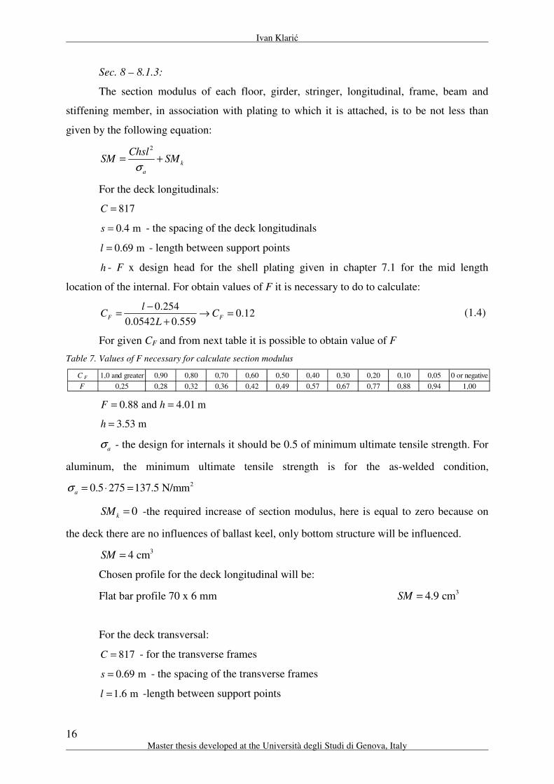
Sec. 8 – 8.1.3:
The section modulus of each floor, girder, stringer, longitudinal, frame, beam and
stiffening member, in association with plating to which it is attached, is to be not less than
given by the following equation:
2
k
a
ChslSM SM
σ= +
For the deck longitudinals:
817C =
0.4 ms = - the spacing of the deck longitudinals
0.69 ml = - length between support points
h - F x design head for the shell plating given in chapter 7.1 for the mid length
location of the internal. For obtain values of F it is necessary to do to calculate:
0.254
0.120.0542 0.559
F F
lC C
L
−= → =
+ (1.4)
For given CF and from next table it is possible to obtain value of F
Table 7. Values of F necessary for calculate section modulus
0.88 and 4.01 mF h= =
3.53 mh =
aσ - the design for internals it should be 0.5 of minimum ultimate tensile strength. For
aluminum, the minimum ultimate tensile strength is for the as-welded condition,
20.5 275 137.5 N/mma
σ = ⋅ =
0kSM = -the required increase of section modulus, here is equal to zero because on
the deck there are no influences of ballast keel, only bottom structure will be influenced.
34 cmSM =
Chosen profile for the deck longitudinal will be:
Flat bar profile 70 x 6 mm 34.9 cmSM =
For the deck transversal:
817C = - for the transverse frames
0.69 ms = - the spacing of the transverse frames
1.6 ml = -length between support points
C F 1,0 and greater 0,90 0,80 0,70 0,60 0,50 0,40 0,30 0,20 0,10 0,05 0 or negative
F 0,25 0,28 0,32 0,36 0,42 0,49 0,57 0,67 0,77 0,88 0,94 1,00

Structure design of a sailing yacht hull by Rules and direct methods
17
“EMSHIP” Erasmus Mundus Master Course, period of study September 2010 - February 2012
0.254
0.380.0542 0.559
F F
lC C
L
−= → =
+
0.57F =
2.29 mh =
2137.5 N/mm
aσ = .
324.03 cmSM =
Chosen profile for the deck longitudinal will be:
Flat bar profile 120 x 12 mm 328.8 cmSM =
For the deck primary longitudinals:
817C =
1.6 ms = - the spacing of the transverse frames
2.76 ml = -length between support points
0.254
0.710.0542 0.559
F F
lC C
L
−= → =
+
0.36F =
1.44 mh =
2137.5 N/mm
aσ = .
3104.28 cmSM =
Chosen profile for the deck longitudinals will be:
T profile: web 250 x 8 mm
flange 100 x 12 mm 3133.82 cmSM =
For the deck main frames:
817C =
2.76 ms = - the spacing of the transverse frames
1.6 ml = -length between support points
0.254
0.380.0542 0.559
F F
lC C
L
−= → =
+
0.57F =
2.29 mh =
2137.5 N/mm
aσ = .
396.14 cmSM =

Ivan Klarić
18 Master thesis developed at the Università degli Studi di Genova, Italy
Chosen profile for the deck longitudinal will be:
T profile: web 250 x 8 mm
flange 60 x 8 mm 3112.43 cmSM =
All section modulus of the profiles are calculated in Microsoft office – excel 2007.
And how it is done it is possible to see from next figures.
Figure 9. Section modulus for flat bar profile
Figure 10. Section modulus for T profile
The web depth to thickness ratio is not exceed 59
Flange with to thickness ratio not more than 12
Flat bar stiffeners the depth to thickness ratio is in general not to exceed 12.
Flat bar profile calculation SM:
b = 6 mm
h = 70 mm h
Varifacation <12: 11,67
SMprofile = 4900,00 mm3
b
SMprofile = 4,90 cm3
Flat bar profile calculation of section modulus:
23 cm
6
b hSM
⋅=
b1 I for the square bh3/12:
Web: h1 I = 10416667 mm4
b = 8 mm I1 = 14400 mm4
h = 250 mm
Flange: Ai * (Zi - Zg)2:
h1 = 12 mm h A * (z - zg)2 = 4,83E+06 mm
3
b1 = 100 mm A1 * (z1 - zg)2
= 8,04E+06 mm3
Area:
A = 2000,00 mm2
Moment of inertia:
A1 = 1200,00 mm2
b I = 1,52E+07 mm4
Σ A + A1 = 3200,00 mm2
I1 = 8,06E+06 mm4
Location of the center of gravity for each element: Σ I + I1 = 2,33E+07 mm4
z = 125 mm
z1 = 256 mm Section modulus of T profile:
Area * center of gravity:
A * z = 250000 mm3
SM = 1,34E+05 mm3
A1 * z1 = 307200 mm3
SM = 133,82 cm3
Σ A*z + A1*z1 = 557200 mm3
Verifecation for web < 59: 31,25
REAL CENTER OF GRAVITY: Verifecation for flange < 12: 8,33
zg = 174,13 mm
T profile calculation of section modulus:
Structure design of a sailing yacht hull by Rules and direct methods
19
“EMSHIP” Erasmus Mundus Master Course, period of study September 2010 - February 2012
Formulas that have been used:
A b h= ⋅ (1.5)
i i
g
i
A zz
A
⋅=∑∑
(1.6)
( )3
2
12
i ii i g
b hI A z z
⋅= + ⋅ − (1.7)
g
ISM
z= (1.8)
According to the ABS – Motor Pleasure Yacht 2000 Ch7A.1.2:
Openings in webs, girders and other structural internal members are to be arranged
clear of concentrated loads or areas of high stresses. Slots in transverses and girders for
longitudinals or beams in these areas are to be fitted with filler plates.
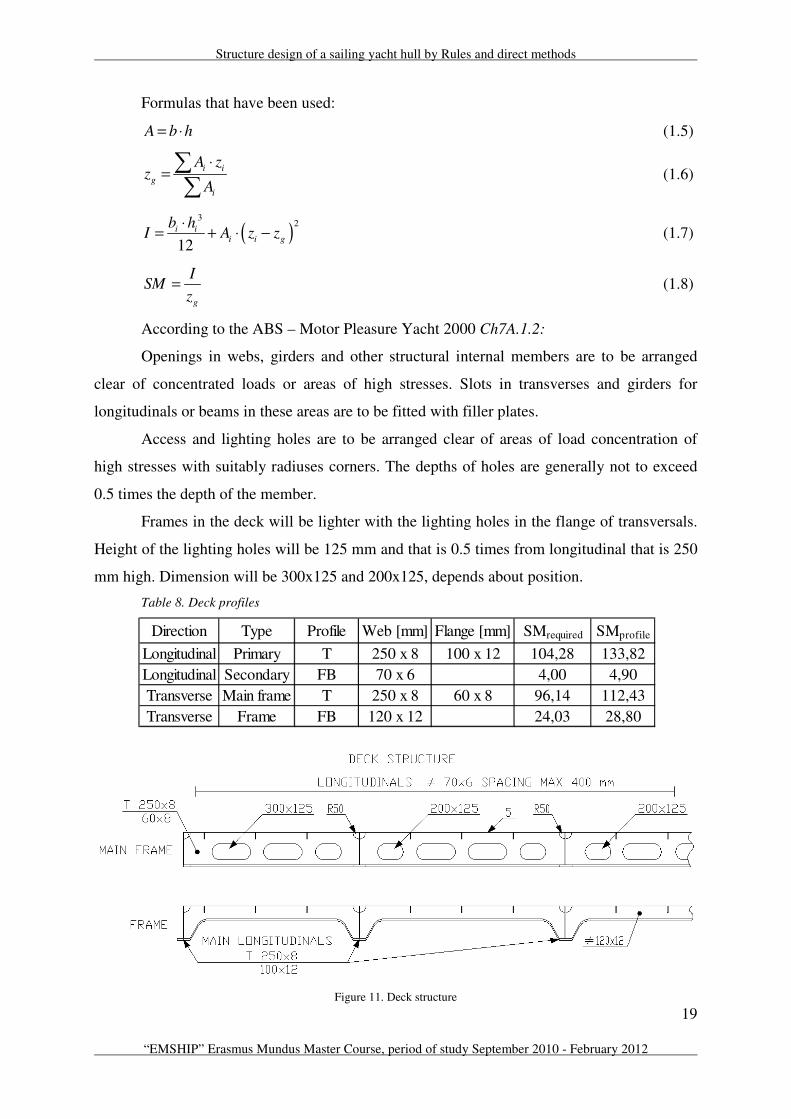
Access and lighting holes are to be arranged clear of areas of load concentration of
high stresses with suitably radiuses corners. The depths of holes are generally not to exceed
0.5 times the depth of the member.
Frames in the deck will be lighter with the lighting holes in the flange of transversals.
Height of the lighting holes will be 125 mm and that is 0.5 times from longitudinal that is 250
mm high. Dimension will be 300x125 and 200x125, depends about position.
Table 8. Deck profiles
Figure 11. Deck structure
Direction Type Profile Web [mm] Flange [mm] SMrequired SMprofile
Longitudinal Primary T 250 x 8 100 x 12 104,28 133,82
Longitudinal Secondary FB 70 x 6 4,00 4,90
Transverse Main frame T 250 x 8 60 x 8 96,14 112,43
Transverse Frame FB 120 x 12 24,03 28,80

Ivan Klarić
20 Master thesis developed at the Università degli Studi di Genova, Italy
2.3 Side Structure Scantling
Sec. 7 – 7.1:
a
pkt sc
σ=
Where:
330 mms = - distance between two side longitudinals
0.7c =
0.01p Fh=
h - the design head, depending about position of the plate, for side plates:
Basic head:
1 13.0 0.14 1.62 15.07 mh d L h= + + → =
Design head:
10.8 12.56 mh h h= → =
F - the design head reduction factor, for side plates:
3.08F = - not less than 0.8D
0.387p =
k - the coefficient varying with the plate panel aspect ratio, according to the equation:
( )( )6
0.5
1 0.623 /k
s l=
+
690 mml = - distance between two frames
0.496k =
2165 N/mma
σ =
Thickness of the side plate is:
7.82 mmt =
After all other requirements are met the thickness for aluminum in general, is to be not
less than s/100 or 2.5 mm whichever is greater. According to this:
3.3 mmt =
Chosen thickness of the side plate will be: 8 mmt =
Sec. 8 – 8.1.3:
2
k
a
ChslSM SM
σ= +

Structure design of a sailing yacht hull by Rules and direct methods
21
“EMSHIP” Erasmus Mundus Master Course, period of study September 2010 - February 2012
For the shell longitudinals:
817C =
0.33 ms = - the spacing of the side longitudinals
0.69 ml = - length between support points
h - F x design head for the shell plating given in chapter 7.1 for the mid length
location of the internal. For obtain values of F it is necessary to do to calculate:
0.254
0.120.0542 0.559
F F
lC C
L
−= → =
+
0.88F = - from the Table 1.
Design head from chapter 7.1: 12.56 mh =
11.05 mh =
2137.5 N/mm
aσ =
0k
SM = -the required increase of section modulus
310.3 cmSM =
Chosen profile for the side longitudinal will be:
Flat bar profile 90 x 8 mm 310.8 cmSM =
For the side transversal:
817C =
0.69 ms = - the spacing of the transverse frames
1.32 ml = - length between support points
0.254
0.30.0542 0.559
F F
lC C
L
−= → =
+
0.67F =
8.41 mh =
2137.5 N/mm
aσ = .
360.07 cmSM =
Chosen profile for the side transversal will be:
T profile: web 160 x 9 mm
flange 90 x 12 mm 365.46 cmSM =
For the side primary longitudinal:
817C =

Ivan Klarić
22 Master thesis developed at the Università degli Studi di Genova, Italy
1.32 ms = - the spacing of the primary longitudinal
0.69 ml = -length between support points
0.254
0.120.0542 0.559
F F
lC C
L
−= → =
+
0.88F =
11.05 mh =
2137.5 N/mm
aσ = .
341.26 cmSM =
Chosen profile for the primary side longitudinal will be:
T profile: web 160 x 7 mm
flange 80 x 12 mm 352 cmSM =
Table 9. Side profiles
Figure 12. Side structure
Direction Type Profile Web [mm] Flange [mm] SMrequired SMprofile
Longitudinal Primary T 160 x 7 80 x 12 60,07 65,46
Longitudinal Secondary FB 90 x 8 10,30 10,80
Transverse Main frame T 160 x 9 90 x 12 41,26 52,00

Structure design of a sailing yacht hull by Rules and direct methods
23
“EMSHIP” Erasmus Mundus Master Course, period of study September 2010 - February 2012
2.4 Bottom Structure Scantling
Sec. 7 – 7.1:
a
pkt sc
σ=
Where:
330 mms = - distance between two bottom longitudinals
0.7c =
0.01p Fh=
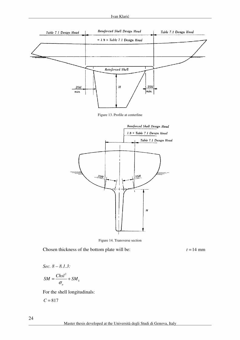
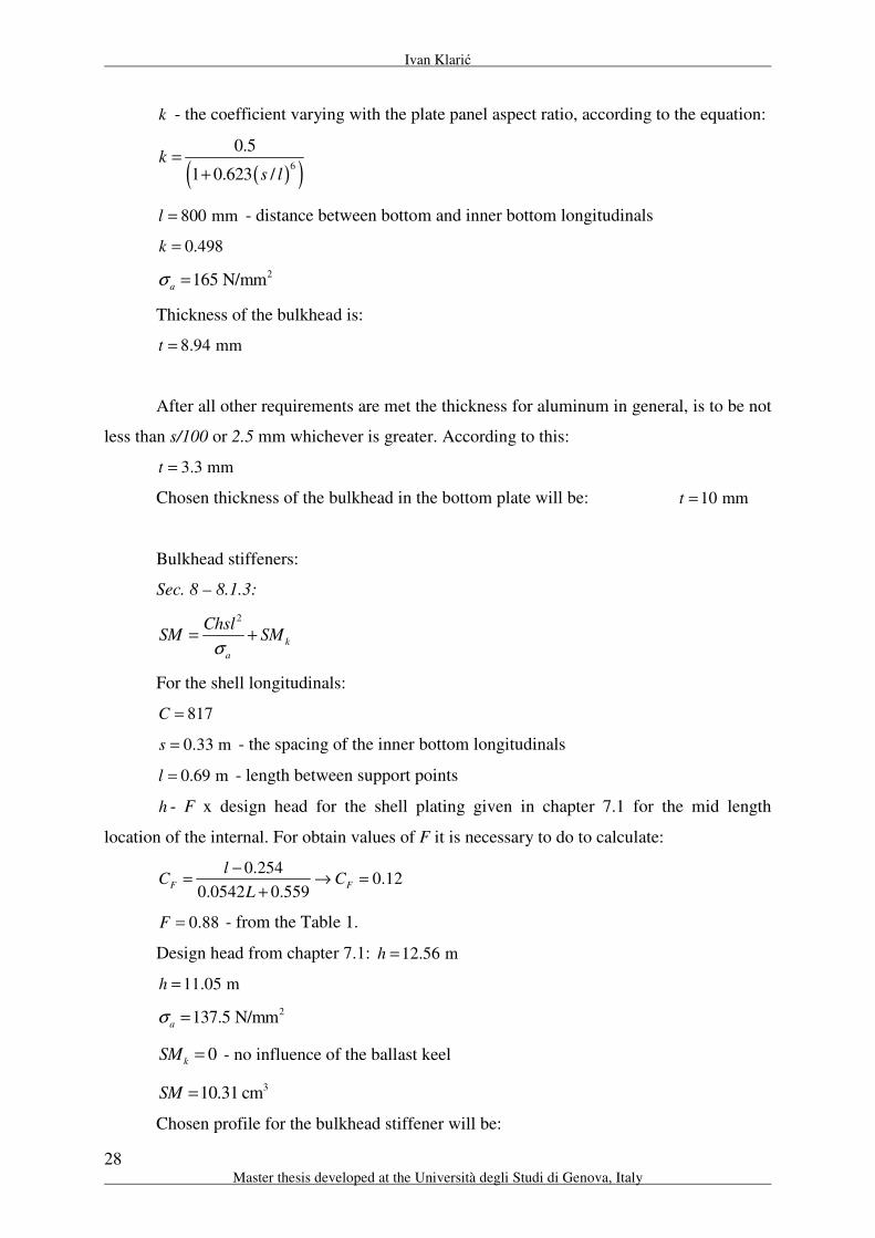
h - the design head, depending about position of the plate, for bottom plates:
Basic head:
1 13.0 0.14 1.62 15.07 mh d L h= + + → =
Design head:
1.8 27.126 mh h h= → = - according to the Figure 13.
F - the design head reduction factor, for bottom plates:
3.85F = - not less than D
1.044p =
k - the coefficient varying with the plate panel aspect ratio, according to the equation:
( )( )6
0.5
1 0.623 /k
s l=
+
690 mml = - distance between two frames
0.496k =
2165 N/mma
σ =
Thickness of the bottom plate is:
12.94 mmt =
After all other requirements are met the thickness for aluminum in general, is to be not
less than s/100 or 2.5 mm whichever is greater. According to this:
3.3 mmt =
The bottom shell thickness is to be increased for the extent shown in next figures:
Ivan Klarić
24 Master thesis developed at the Università degli Studi di Genova, Italy
Figure 13. Profile at centerline
Figure 14. Transverse section
Chosen thickness of the bottom plate will be: 14 mmt =
Sec. 8 – 8.1.3:
2
k
a
ChslSM SM
σ= +
For the shell longitudinals:
817C =

Structure design of a sailing yacht hull by Rules and direct methods
25
“EMSHIP” Erasmus Mundus Master Course, period of study September 2010 - February 2012
0.33 ms = - the spacing of the bottom longitudinals
0.69 ml = - length between support points
h - F x design head for the shell plating given in chapter 7.1 for the mid length
location of the internal. For obtain values of F it is necessary to do to calculate:
0.254
0.120.0542 0.559
F F
lC C
L
−= → =
+
0.88F = - from the Table 1.
Design head from chapter 7.1: 12.56 mh =
1.2 15.07 mh h= =
2137.5 N/mm
aσ =
k k
k
a
NW YSM
nσ= - for the floors and frames in way of the ballast keel
0.5N =
52189 Nk
W = - weight of the ballast keel
3.756 mk
Y = - vertical distance from mid-depth of floor at centerline to center of
gravity of ballast keel in m
26n = - number of floors in way of keel, not less than 3
312.3 cm
kSM =
322.6 cmSM =
Chosen profile for the bottom longitudinal will be:
Flat bar profile 120 x 12 mm 328.8 cmSM =
Inner bottom:
Position of inner bottom will be 2950 mm from the center line.
Sec. 7 – 7.1:
a
pkt sc
σ=
Where:
330 mms = - distance between two inner bottom longitudinals
1c =
0.01p Fh=

Ivan Klarić
26 Master thesis developed at the Università degli Studi di Genova, Italy
h - the design head, depending about position of the plate, for inner bottom plates:
Basic head:
1 13.0 0.14 1.62 15.07 mh d L h= + + → =
Design head:
1.2 18.08 mh h h= → =
F - the design head reduction factor, for inner bottom plates:
3.85F = - not less than D
0.696p =
k - the coefficient varying with the plate panel aspect ratio, according to the equation:
( )( )6
0.5
1 0.623 /k
s l=
+
690 mml = - distance between two frames
0.496k =
2165 N/mma
σ =
Thickness of the inner bottom plate is:
10.57 mmt =
After all other requirements are met the thickness for aluminum in general, is to be not
less than s/100 or 2.5 mm whichever is greater. According to this:
3.3 mmt =
Chosen thickness of the inner bottom plate will be: 12 mmt =
Sec. 8 – 8.1.3:
2
k
a
ChslSM SM
σ= +
For the shell longitudinals:
817C =
0.33 ms = - the spacing of the inner bottom longitudinals
0.69 ml = - length between support points
h - F x design head for the shell plating given in chapter 7.1 for the mid length
location of the internal. For obtain values of F it is necessary to do to calculate:

Structure design of a sailing yacht hull by Rules and direct methods
27
“EMSHIP” Erasmus Mundus Master Course, period of study September 2010 - February 2012
0.254
0.120.0542 0.559
F F
lC C
L
−= → =
+
0.88F = - from the Table 1.
Design head from chapter 7.1: 12.56 mh =
11.05 mh =
2137.5 N/mm
aσ =
0k
SM = - no influence of the ballast keel
310.31 cmSM =
Chosen profile for the bottom longitudinal will be:
Flat bar profile 70 x 6 mm 311.67 cmSM =
Usually where main frame is positioned, in the bottom it is possible to do bulkhead
between two bottom tanks. So the scantling will be done for calculation of the bulkhead in the
bottom with stiffeners of the bulkhead and also when the tanks are located in bottom.
Scantling of opening and stiffeners will be done.
Thickness of the bulkhead in the bottom structure:
Sec. 7 – 7.1:
a
pkt sc
σ=
Where:
330 mms = - distance between two stiffeners of bulkhead
1c =
0.01p Fh=
h - the design head, depending about position of the plate, for bulkhead:
Basic head:
1 13.0 0.14 1.62 15.07 mh d L h= + + → =
Design head:
0.8 12.56 mh h h= → =
F - the design head reduction factor, for side plates:
3.85F = - not less than D
0.484p =
Ivan Klarić
28 Master thesis developed at the Università degli Studi di Genova, Italy
k - the coefficient varying with the plate panel aspect ratio, according to the equation:
( )( )6
0.5
1 0.623 /k
s l=
+
800 mml = - distance between bottom and inner bottom longitudinals
0.498k =
2165 N/mma
σ =
Thickness of the bulkhead is:
8.94 mmt =
After all other requirements are met the thickness for aluminum in general, is to be not
less than s/100 or 2.5 mm whichever is greater. According to this:
3.3 mmt =
Chosen thickness of the bulkhead in the bottom plate will be: 10 mmt =
Bulkhead stiffeners:
Sec. 8 – 8.1.3:
2
k
a
ChslSM SM
σ= +
For the shell longitudinals:
817C =
0.33 ms = - the spacing of the inner bottom longitudinals
0.69 ml = - length between support points
h - F x design head for the shell plating given in chapter 7.1 for the mid length
location of the internal. For obtain values of F it is necessary to do to calculate:
0.254
0.120.0542 0.559
F F
lC C
L
−= → =
+
0.88F = - from the Table 1.
Design head from chapter 7.1: 12.56 mh =
11.05 mh =
2137.5 N/mm
aσ =
0k
SM = - no influence of the ballast keel
310.31 cmSM =
Chosen profile for the bulkhead stiffener will be:
Structure design of a sailing yacht hull by Rules and direct methods
29
“EMSHIP” Erasmus Mundus Master Course, period of study September 2010 - February 2012
Flat bar profile 70 x 6 mm 311.67 cmSM =
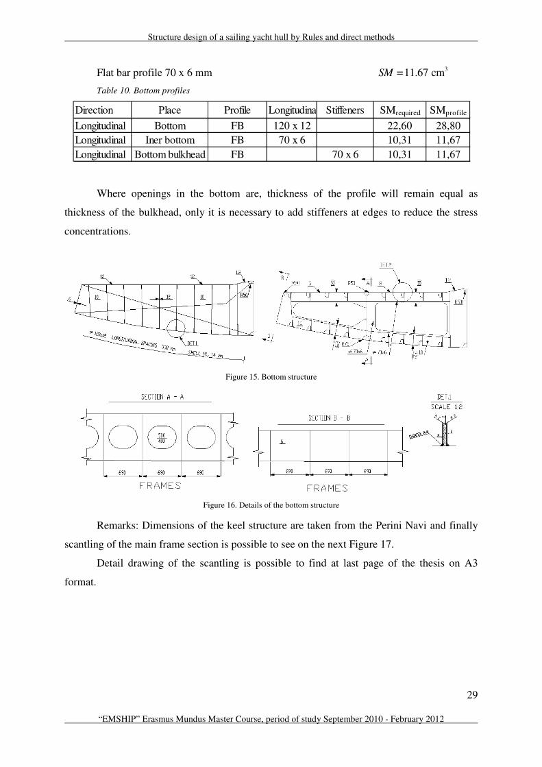
Table 10. Bottom profiles
Where openings in the bottom are, thickness of the profile will remain equal as
thickness of the bulkhead, only it is necessary to add stiffeners at edges to reduce the stress
concentrations.
Figure 15. Bottom structure
Figure 16. Details of the bottom structure
Remarks: Dimensions of the keel structure are taken from the Perini Navi and finally
scantling of the main frame section is possible to see on the next Figure 17.
Detail drawing of the scantling is possible to find at last page of the thesis on A3
format.
Direction Place Profile Longitudinals Stiffeners SMrequired SMprofile
Longitudinal Bottom FB 120 x 12 22,60 28,80
Longitudinal Iner bottom FB 70 x 6 10,31 11,67
Longitudinal Bottom bulkhead FB 70 x 6 10,31 11,67
Ivan Klarić
30 Master thesis developed at the Università degli Studi di Genova, Italy
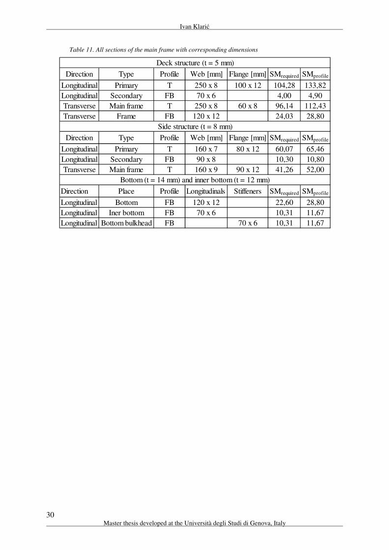
Table 11. All sections of the main frame with corresponding dimensions
Direction Type Profile Web [mm] Flange [mm] SMrequired SMprofile
Longitudinal Primary T 250 x 8 100 x 12 104,28 133,82
Longitudinal Secondary FB 70 x 6 4,00 4,90
Transverse Main frame T 250 x 8 60 x 8 96,14 112,43
Transverse Frame FB 120 x 12 24,03 28,80
Direction Type Profile Web [mm] Flange [mm] SMrequired SMprofile
Longitudinal Primary T 160 x 7 80 x 12 60,07 65,46
Longitudinal Secondary FB 90 x 8 10,30 10,80
Transverse Main frame T 160 x 9 90 x 12 41,26 52,00
Direction Place Profile Longitudinals Stiffeners SMrequired SMprofile
Longitudinal Bottom FB 120 x 12 22,60 28,80
Longitudinal Iner bottom FB 70 x 6 10,31 11,67
Longitudinal Bottom bulkhead FB 70 x 6 10,31 11,67
Deck structure (t = 5 mm)
Side structure (t = 8 mm)
Bottom (t = 14 mm) and inner bottom (t = 12 mm)

Structure design of a sailing yacht hull by Rules and direct methods
31
“EMSHIP” Erasmus Mundus Master Course, period of study September 2010 - February 2012
Figure 17. Main frame of the sailing yacht

Ivan Klarić
32 Master thesis developed at the Università degli Studi di Genova, Italy
3. ALUMINUM
Development of Metal Boats
Although older than fiberglass, metal boats are quite a modern development compared
to wood construction. The first known all-metal boat was a riveted-iron barge built in 1787 by
J. Wilkinson. Although this barge was successful, when Richard Trivithick and Robert
Dickenson later proposed all-iron ships in 1809, they were met with incredulity and mirth.
After all, everyone knew that iron was heavier than water and would sink. Nine years later, in
1818, first all metal commercial self-propelled boat, the Vulcan, was constructed at Faskine,
near Glasgow. And she stayed in service until 1875. Metal hulls were now fully accepted,
particularly for craft over 60 m, because they were nailed, screwed and bolted, then wooden
structures could ever hope to be.
Perhaps surprisingly, experiments with aluminum vessels started not long after steel.
The firs all aluminum boat is believed to be a leeboard sailboat built in 1890. Probably the
first all aluminum powerboat was the Mignon, constructed in Switzerland in 1892, it was
driven by 2-hp (1.5 kW) naphtha engine. In 1894, several 5.48 m surfboats were built of
aluminum in the United States for a polar expedition. Weighing in at 170 kg compared to 773
kg for the equivalent screw fastened wood, they were first aluminum boats built in North
America.
3.1. Types of Aluminum
Production of aluminum at the present time the ore, bauxite, is mined containing
roughly 56 per cent aluminum. The actual extraction of the aluminum from the ore is a
complicated and costly process involving two distinct stages. Firstly the bauxite is purified to
obtain pure aluminum oxide known as alumina; the alumina is then reduced to a metallic
aluminum. The metal is cast in pig or ingot forms and alloys are added where required before
the metal is cast into billets or slabs for subsequent rolling, extrusion, or other forming
operation. Sectional material is mostly produced by the extrusion process. This involves
forcing a billet of the hot material through a die of the desired shape. More intricate shapes
are produced by this method than are possible with steel where the sections are rolled.
However, the range of thickness of section may be limited since each thickness requires a
different die.
Structure design of a sailing yacht hull by Rules and direct methods
33
“EMSHIP” Erasmus Mundus Master Course, period of study September 2010 - February 2012
Pure aluminum has a low tensile strength and is of little use for structural purposes;
therefore the pure metal is alloyed with small percentages of other materials to give greater
tensile strength. There is a wide assortment of aluminum alloys and only true marine
aluminum alloys will stand up to corrosion in salt water. Aluminum is also isotropic material.
That is meaning that the strength is uniform in all direction. No matter which way you
oriented the plate, it has the same strength up or down, fore-n-aft, diagonally, and even
through the thickness of the plate [4].
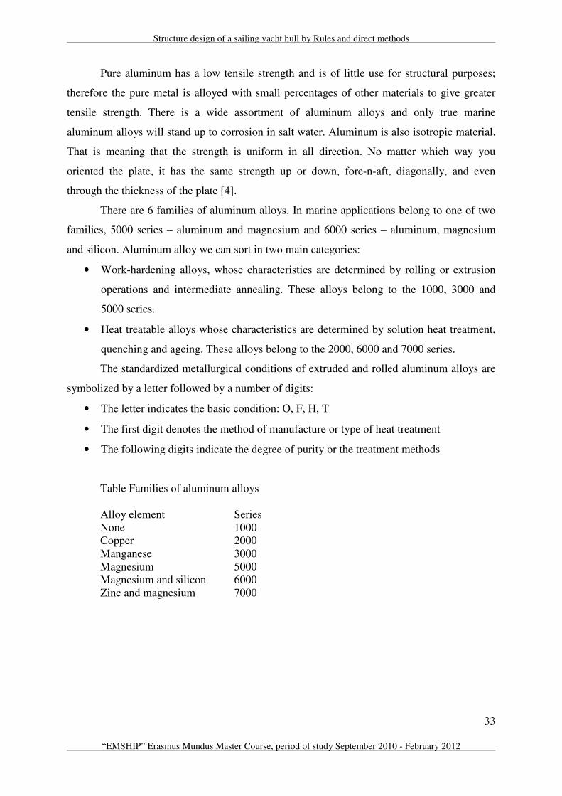
There are 6 families of aluminum alloys. In marine applications belong to one of two
families, 5000 series – aluminum and magnesium and 6000 series – aluminum, magnesium
and silicon. Aluminum alloy we can sort in two main categories:
• Work-hardening alloys, whose characteristics are determined by rolling or extrusion
operations and intermediate annealing. These alloys belong to the 1000, 3000 and
5000 series.
• Heat treatable alloys whose characteristics are determined by solution heat treatment,
quenching and ageing. These alloys belong to the 2000, 6000 and 7000 series.
The standardized metallurgical conditions of extruded and rolled aluminum alloys are
symbolized by a letter followed by a number of digits:
• The letter indicates the basic condition: O, F, H, T
• The first digit denotes the method of manufacture or type of heat treatment
• The following digits indicate the degree of purity or the treatment methods
Table Families of aluminum alloys
Alloy element Series
None 1000
Copper 2000
Manganese 3000
Magnesium 5000
Magnesium and silicon 6000
Zinc and magnesium 7000

Ivan Klarić
34 Master thesis developed at the Università degli Studi di Genova, Italy
Table Aluminum Boatbuilding Alloy Physical Properties
UTS, psi x Yield, psi x
Alloy Temper Form 1.000 (mPa) 1.000 (mPa) Elongation
5083 H111 extrusions 40 (276) 24 (165) 16%
H321 sheet&plate 44 (303) 31 (214) 16%
H323 sheet 45 (310) 34 (234) 16%
H324 sheet 50 (345) 39 (269) 16%
H321 extrusions 41 (283) 29 (200) 16%
5086 H111 extrusions 35 (241) 21 (145) 16%
H112 plate 44 (241) 16 (193) 14%
H32 sheet&plate 40 (276) 28 (234) 12%
H34 drqwn tube 44 (303) 34 (131) 10%
5054 H111 extrusions 33 (227) 19 (131) 14%
H112 extrusions 36 (214) 12 (83) 18%
H32 sheet&plate 39 (248) 26 (179) 10%
H34 sheet&plate 42 (269) 29 (227) 10%
5056 H111 extrusions 42 (289) 26 (179) 18%
H112 extrusions 41 (283) 19 (131) 22%
H321 sheet&plate 46 (317) 33 (227) 16%
H323 plate 48 (331) 36 (248) 16%
H324 sheet 53 (365) 41 (283) 16%
6061 T6 sheet&plate 42 (289) 35 (241) 17%
T6 extrusions 38 (262) 35 (241) 17%
T6 rod&bar 42 (289) 35 (241) 17%
T6 drawn tube 42 (289) 35 (241) 17%
T6 pipe 42 (289) 35 (241) 17%
Note : Modulus of elasticity E = 68.981 mPa
UTS = Ultimate Tensile Strength
Elongation is a percent of a 50 mm sample.
Material of the boat will be from group 5083 and that group has the highest strength
non-heat-treatable alloy in commercial use. It has good formability and welds ability and
retains excellent tensile strength in the weld zone by virtue of its as-rolled properties. It is
used most often in structures requiring high weld efficiency and maximum weld strength.
5083 also has excellent resistance to corrosion. And from that group it is chosen the H321
type of aluminum. H321 have next chemical properties.

Structure design of a sailing yacht hull by Rules and direct methods
35
“EMSHIP” Erasmus Mundus Master Course, period of study September 2010 - February 2012
Table Aluminum 5083 – H321 Chemical properties
Component Wt. % Component Wt. % Component Wt. %
Al 92.4 - 95.6 Mg 4 - 4.9 Si Max 0.4
Cr 0.05 – 0.25 Mn 0.4 - 1 Ti Max 0.15
Cu Max 0.1 Other, each Max 0.05 Zn Max 0.25
Fe Max 0.4 Other, each Max 0.15
Physical properties:
Density is 3
kg2.66
mρ =
Melting range o570 640 C−
Table Aluminum 5083 – H321 Mechanical properties
Hardness, Brinell 85 Hardness, Knoop 109
Hardness, Rockwell A 36.5 Hardness, Rockwell B 53
Hardness, Vickers 96 Ultimate Tensile Strength 317 MPa
Tensile Yield Strength 228 MPa Elongation at Break 16%
Modulus of Elasticity 70.3 GPa Compressive Modulus 71.7 GPa
Poissn’s Ratio 0,33 Fatigue Strength 159 MPa
Shear Modulus 26.4 GPa Shear Strength 190 MPa
3.2. Advantages of Aluminum:
1. Light aluminum. Aluminum is lighter than steel for the same strength. For example
aluminum plate should be between 1.25 to 1.5 times thicker than steel for the same strength.
Aluminum weighs 2.691 kg/m3 versus steel 7.849 kg/m
3 and that is only 34 percent of steel
weight. Even taking the larger thickness’s multiplier of 1.5, this means that aluminum is about
half the weight for the same strength.
2. More stable and faster aluminum boats. The light weight obtainable from
aluminum construction lowers the centre of gravity of a boat, making it more stable and thus
more seaworthy. Less weight also means you can go faster with the same power or sail area,
or have a higher ballast ratio in a sailboat for more sail area and improved performance.
Alternately you can use less power for the same speed or get greater range with the same
tankage.
3. Aluminum superstructure on steel hulls. It is so difficult to make steel light
enough and most of vessels must use wood, FRP2, or aluminum superstructures rather than
2 FRP – Fiber-Reinforced Polymer
Ivan Klarić
36 Master thesis developed at the Università degli Studi di Genova, Italy
steel. If they don’t, it is nearly impossible to keep the boat’s center of gravity low enough for
adequate stability.
4. Light weight equals labor – saving. The lighter weight of the components makes
building in aluminum less labor-intensive than steel. For example steel plate of 37 m2 would
weight 1360 kg and would require careful handling and heavy gear. But for the same
dimension, aluminum plate would weigh just 640 kg.
5. Easier to work in aluminum. Aluminum is softer and easier to bend, cut, and
form. It cuts about three times faster than steel. Aluminum bends so easily, that round bilge
hulls are little problem. It can be cut with ordinary woodworking equipment, and quickly and
easily drilled, sanded and filed to exact dimension.
6. No compromise on the hull shape. The freedom to build inexpensively nearly any
hull shape in aluminum means that the hull form doesn’t have to be compromised with
developable surfaces or chines when they are not wanted. This leads to more efficient
hydrodynamics for better performance and increased seakindliness.
7. Faster welding. Welding aluminum is roughly three times faster than welding steel.
Even allowing for somewhat heavier welds (i.e. more passes) for the comparably thicker
aluminum plate of the same strength, the total hours in welding aluminum should be about
half that for a similar steel hull.
8. No rust, lower maintenance. Aluminum doesn’t rust at all. It can corrode when it
is in contact with dissimilar metals or from stray electrical currents. Aluminum is so corrosion
resistant and totally rust free that it doesn’t even have to be painted above the waterline or on
the inside.
9. No added plate thickness to allow for corrosion. Rusting wastes away the steel
plates and the plates are getting thinner with age and that is not case with aluminum. Steel
will lose about 0.1 mm of thickness every year.
10. Aluminum is nonsparking and nonmagnetic. Being nonsparking makes
aluminum safer both in the building shop and in operation. Fires can’t be ignited by the
friction spark of some heavy object falling or scraping against the aluminum structure. The
lack of magnetic interfaces is a great plus for navigation and electronics.
11. Aluminum is less sensitive to stress risers. Aluminum’s plastic deformation
offers another benefit as well. Steel is particularly sensitive to sharp corners in construction.
This is called notch sensitivity, the notches or sharp corners are called stress risers.
12. No attack by bacteria. Aluminum hulls are not subject to attack by sulfate
reducing bacteria. These little known bacteria can accumulate in bilges, ballast tanks and fuel

Structure design of a sailing yacht hull by Rules and direct methods
37
“EMSHIP” Erasmus Mundus Master Course, period of study September 2010 - February 2012
tanks, usually in commercial vessels and can eat their way through 8 mm of steel plate in a
year. They can cause catastrophic corrosion quickly if not detected.
13. Reducing labor costs compensate for increased material costs. The much
greater ease of working with and forming aluminum substantially reduces labor costs. Usually
the labor cost reduction combined with the lower total weight of metal purchased can be
enough to offset the substantially higher cost of the aluminum itself.
3.3. Disadvantages of Aluminum
No material is perfect and in spite of the many pluses listed previously, aluminum
does have some drawback compared to steel.
1. Aluminum is considerably more expensive
2. Less abrasion resistant. Aluminum hulls are less resistant to abrasion. Steel is the
best material when abrasion is in the question. And because of that steel is the best material
for build tugs, canal boats, barges and dredges.
3. Aluminum can melt and burn in a fire. For a structural metal, aluminum has a
low melting point, at approximately 592 oC. It can even burn in an exceptionally intense fire.
Steel with melting point of approximately 1427 oC is the only truly fireproof boatbuilding
material. But again comparing with a wood aluminum is more fire resistant than wood.
4. Welding equipment is more expensive. The gas shielded welding equipment
required for aluminum is more expensive than the stick/electrode welding used for steel. And
the best for welding aluminum is in the enclosed building. If not, breezes will blow the gas
shield away from the arc, causing defective welds.
5. Qualified workers and equipment are harder to find.
6. Aluminum alloy is harder to locate. Aluminum alloy are frequently tough to find
in many regions outside of North America and Europe. Even where aluminum suppliers and
manufactures are common, it can be difficult to purchase the sizes and quantities of material
necessary for small boat project.

Ivan Klarić
38 Master thesis developed at the Università degli Studi di Genova, Italy
4. FINITE ELEMENTH METHOD
A ship structure is, in general, so huge and statically indeterminate that 3-D analysis is
not easy. For the strength analysis of the structure methods can be categorized as:
Analysis using simple beam theory
Analysis of frame structure: Slope deflection method
Analysis of three dimensional structure: Finite element method
The finite element method (FEM) is an essential and powerful tool for solving
structural problems not only in the field of shipbuilding but also in the design of the most
industrial products and even in non-structural fields. FEM can be used for a wide variety of
problems in linear or nonlinear solid mechanics, dynamics, and ships structural stability
problems, in accordance with the development of computer technology and its popularization.
The conventional method in solving stress and deformation problems is an analytical
one using theories of beams, columns and plates, etc. Hence its application is restricted to
most simple structures and loads. On the other hand FEM:
• Divides a structure into small elements
• Assumes each element to be a mathematical model
• Assembles the elements and solves the overall
Figure 18. Methodology of FEM [5]
Typical elements of FEM are:
Figure 19. Elements types in FEM [5]

Structure design of a sailing yacht hull by Rules and direct methods
39
“EMSHIP” Erasmus Mundus Master Course, period of study September 2010 - February 2012
Characteristics of FEM are as follows:
• It doesn’t give exact solution but solves approximately, because structures are
modeled as a combination of simple elements and/or loads.
• It is a kind of numerical experiment without experimental devices, models, or
instruments. Hence it is economical and time-savings.
• It can solve actual structural problems by using some models, although their shapes
and loads are complex. It is even used for non-structural problems.
• It is used for a wide variety of steel, nonferrous materials and complex materials.
• It relies on computer technology for both hardware and software
• It is applicable as a black box tool; even engineers do not have to know the theory,
because there are many general purpose FEM programs which are easy to operate.
How to approach to the FEM analysis is the best to understand from the next figure.
Figure 20. Approach to FEM analysis [5]
So the first step is to choose appropriate analysis program for the specified problem,
then the modeling is done by determining the appropriate size of the structure. If model is

Ivan Klarić
40 Master thesis developed at the Università degli Studi di Genova, Italy
symmetric it is possible to reduce the size of the model by choosing suitable boundary
conditions and loading conditions. After, it is necessary to prepare the geometrical data of the
finite elements with visual checking of the validity of the input data through the computer
display. The loading dates as well as the boundary conditions of the structure are then added.
Than execute the program for analysis, calculated results must be assessed to check whether
could be some error in the input date in view of the calculated deformation, stress, etc. If there
was mistake in the input or misunderstanding of the problem the procedure should be repeated
from the beginning [5].

Structure design of a sailing yacht hull by Rules and direct methods
41
“EMSHIP” Erasmus Mundus Master Course, period of study September 2010 - February 2012
5. FINITE ELEMENTH METHOD ANALYSIS
For the analysis of the structure next software’s have been used; models have been
done in SolidWorks 2010 and ANSYS Workbench version 13.0, multi-purpose analysis
software, was chosen to perform the modeling of the models.
SolidWorks is a 3D mechanical CAD (computer-aided design) program that runs on
Microsoft Windows. It was founded in 1993 with headquarters in Waltham, Massachusetts,
USA. That is a parasolid-based solid modeler, and utilizes a parametric feature-based
approach to create models and assemblies.
ANSYS is an engineering simulation software (computer-aided engineering, or CAE),
with headquarters in Cononsburg, Pennsylvania, USA. It has the ability to handle a very well
as perform all the analysis that was needed for the project. It can vary mesh densities through-
out model to allow for run-optimization, create high-precision results based on the stress
fields that developed and the model could handle arbitrary geometries. FEM analysis will not
be performed for the all hull structure; instead it will be done just for some parts of the
structure. All parts that will be analyzed in this chapter are parts of the 58 m sailing yacht,
2193 series, built in Perini Navi shipyard.
Figure 21. Sailing yacht 2193 series [6]
From the next Figure 22 it is possible to see the parts that had been analyzing in Perini
Navi. Those are:
• Main mast base foundation
• Keel – Structure connection

Ivan Klarić
42 Master thesis developed at the Università degli Studi di Genova, Italy
Figure 22. Parts of ship hull structure on which it were performed FEM analysis
5.1. Main Mast Base Foundation
Main mast base foundation was first project that was done in Perini Navi shipyard.
This project was chosen to be the first because of the construction simplicity and in beginning
it is necessary to become familiar with the software, to verify the entire program features that
are necessary to simulate reality and to obtain good results, however it was needed to set up
the parameters to perform the calculations. From the shipyard’s point of view, it was
interesting to perform such analysis because at the ship shown on Figure 21, main mast base
foundation was already built and in meanwhile the mast design was changed, because of that,
the new loads coming from the mast was changed. And the existing main mast base
foundation was not design for that new mast, new loads. So it was necessary to obtain what
are the stresses in existing main mast foundation coming from the new mast and to solve a
problem, if problem does exist. At Figure 23 are shown elements of the main mast base
foundation structure. It is compose of one bottom and top plate, one longitudinal and six
brackets. Because of the construction and load symmetry, model will be cut at longitudinal
and only half of the model will be analyzed.

Structure design of a sailing yacht hull by Rules and direct methods
43
“EMSHIP” Erasmus Mundus Master Course, period of study September 2010 - February 2012
Figure 23. Parts of main mast base construction
Figure 24. Dimension of the main mast base foundation
Foundation is subjected to two different load cases. First and main load is coming
from the main mast on the structure and its value is 3167 kN. Second load case is coming
from the jacks acting on main mast base, there are two jacks and force on each jack is 1100
kN (Figure 25).
Two load cases:
• Main load – from mast 3167 kN
• Load on jack – 1100 kN
Boundary condition is set on the bottom plate and it will be fixed support on the
bottom plate and symmetry is set around longitudinal stiffener or around z axis.

Ivan Klarić
44 Master thesis developed at the Università degli Studi di Genova, Italy
Figure 25. Visualization of the first and second load case of main mast base foundation
Figure 26. Connection of the mast with the structure for the first load case
Figure 27. Connection of the mast with the structure for the second load case
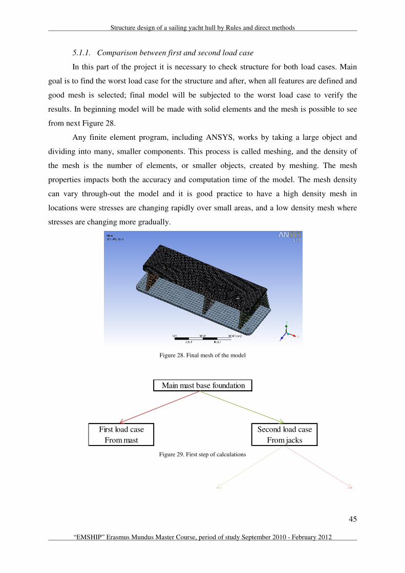
Structure design of a sailing yacht hull by Rules and direct methods
45
“EMSHIP” Erasmus Mundus Master Course, period of study September 2010 - February 2012
5.1.1. Comparison between first and second load case
In this part of the project it is necessary to check structure for both load cases. Main
goal is to find the worst load case for the structure and after, when all features are defined and
good mesh is selected; final model will be subjected to the worst load case to verify the
results. In beginning model will be made with solid elements and the mesh is possible to see
from next Figure 28.
Any finite element program, including ANSYS, works by taking a large object and
dividing into many, smaller components. This process is called meshing, and the density of
the mesh is the number of elements, or smaller objects, created by meshing. The mesh
properties impacts both the accuracy and computation time of the model. The mesh density
can vary through-out the model and it is good practice to have a high density mesh in
locations were stresses are changing rapidly over small areas, and a low density mesh where
stresses are changing more gradually.
Figure 28. Final mesh of the model
Figure 29. First step of calculations
From mast From jacks
Main mast base foundation
First load case Second load case

Ivan Klarić
46 Master thesis developed at the Università degli Studi di Genova, Italy
Figure 30. Total deformation for the first and second load case
From Figure 30 it is possible to see that deformation is almost twice bigger when
second load case is acting on structure. For second load case total deformation is 18.42 mm
and for the first load case 9.85 mm.
Figure 31. Normal stress in the top plate for the second load case
Normal stress is twice bigger in top plate for second load case and that load case will
be applied for the next research of the structure.
Stresses and strains have six components in ANSYS, x, y, z, xy, yz and xz. For
stresses and strains, components can be required under Normal (x, y, z) and Shear (xy, yz,
xz).
Comparison: First load case Second load case
Total deformation 9.85 mm 18.42 mm
Normal stress 479 MPa 913 MPa
5.1.2. Comparison between shell and solid element
Model will be modelled and verified for two types of elements:
• Shell element
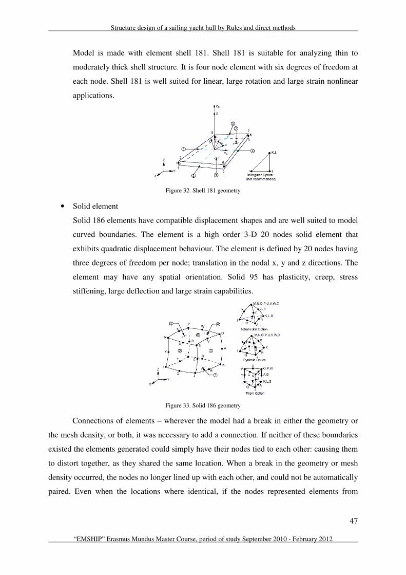
Structure design of a sailing yacht hull by Rules and direct methods
47
“EMSHIP” Erasmus Mundus Master Course, period of study September 2010 - February 2012
Model is made with element shell 181. Shell 181 is suitable for analyzing thin to
moderately thick shell structure. It is four node element with six degrees of freedom at
each node. Shell 181 is well suited for linear, large rotation and large strain nonlinear
applications.
Figure 32. Shell 181 geometry
• Solid element
Solid 186 elements have compatible displacement shapes and are well suited to model
curved boundaries. The element is a high order 3-D 20 nodes solid element that
exhibits quadratic displacement behaviour. The element is defined by 20 nodes having
three degrees of freedom per node; translation in the nodal x, y and z directions. The
element may have any spatial orientation. Solid 95 has plasticity, creep, stress
stiffening, large deflection and large strain capabilities.
Figure 33. Solid 186 geometry
Connections of elements – wherever the model had a break in either the geometry or
the mesh density, or both, it was necessary to add a connection. If neither of these boundaries
existed the elements generated could simply have their nodes tied to each other: causing them
to distort together, as they shared the same location. When a break in the geometry or mesh
density occurred, the nodes no longer lined up with each other, and could not be automatically
paired. Even when the locations where identical, if the nodes represented elements from

Ivan Klarić
48 Master thesis developed at the Università degli Studi di Genova, Italy
different mesh sizes or object an additional connection was still needed to link the nodes
together structurally.
In second step it is necessary to verify the results of shell and solid elements to the
second load case of main mast base foundation.
Figure 34. Second step of calculations
This kind of calculation is necessary to perform, because if results are similar it is
better to work with shell elements. With shell element is much faster to perform analysis,
because model will be modelled with smaller number of elements and that is leading to the
faster calculation or faster CPU time.
Next results will be compared:
• Von – Mises stress
• Normal stress
• Shear stress
• Total deformation
• Error – because of too seldom mesh
One remark about figures of the results, it is possible to notice that figure for shell and
solid are looking quite the same, from the thickness of element point of view. Actually
graphical presentation for the results of the models is always with true thickness of the model
and never just as a surface. But that models are really from surfaces and solids, that will be
proven at the next Figure 35 and Figure 36.
Solid elements
From mast From jacks
Shell elements
Main mast base foundation
First load case Second load case
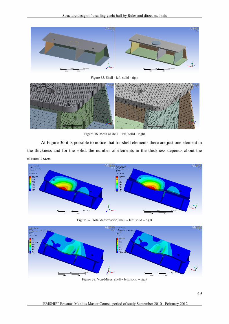
Structure design of a sailing yacht hull by Rules and direct methods
49
“EMSHIP” Erasmus Mundus Master Course, period of study September 2010 - February 2012
Figure 35. Shell - left, solid - right
Figure 36. Mesh of shell – left, solid – right
At Figure 36 it is possible to notice that for shell elements there are just one element in
the thickness and for the solid, the number of elements in the thickness depends about the
element size.
Figure 37. Total deformation, shell – left, solid – right
Figure 38. Von-Mises, shell – left, solid – right

Ivan Klarić
50 Master thesis developed at the Università degli Studi di Genova, Italy
Figure 39. Normal stress, shell – left, solid – right
Figure 40. Shear stress, shell – left, solid – right
Figure 41. Total error, shell – left, solid – right
Comparison: Solid element Shell element
Total deformation 19.45 mm 20.07 mm
Von-Mises 1812 MPa 1610 MPa
Normal stress (tension) 949 MPa 1034 MPa
Normal stress (compression) 1384 MPa 1125 MPa
Shear stress 368 MPa 253 MPa
The most interesting area is top plate; therefore the main focus and observation of
results will be on the top plate.

Structure design of a sailing yacht hull by Rules and direct methods
51
“EMSHIP” Erasmus Mundus Master Course, period of study September 2010 - February 2012
Figure 42. Top view, shell – left, solid - right
Figure 43. Model with shell elements – bottom view
From all these photos above, it is possible to conclude that both of elements
types, shell or solid are giving similar results. According with this comparison, shell elements
will be applied for the final model calculation.
From Figure 41 is also possible to notice that shell elements are making bigger errors
then solid elements. So with shell elements it will be necessary to work with denser mesh,
however even with denser mesh, number of elements will be less than with the solids and
calculations will be faster. Also at this structure with this load case the shear stress isn’t big
and in next models it will be take in consideration only the Von-Mises stress and normal
stress, and still every time it will be verified shear stress too and if it will be necessary to
mention it in some case, it will be done too.
5.1.3. Linear analysis
A linear material model assumes stress to be proportional to strain. That means it
assumed that the higher the load applied, the higher the stresses and deformation will be,
proportional to the changes in the load. It also assumes that no permanent deformations will
result, and that once the load has been removed the model will always return to its original
shape.
Figure 44. Stress – strain relation for linear analysis
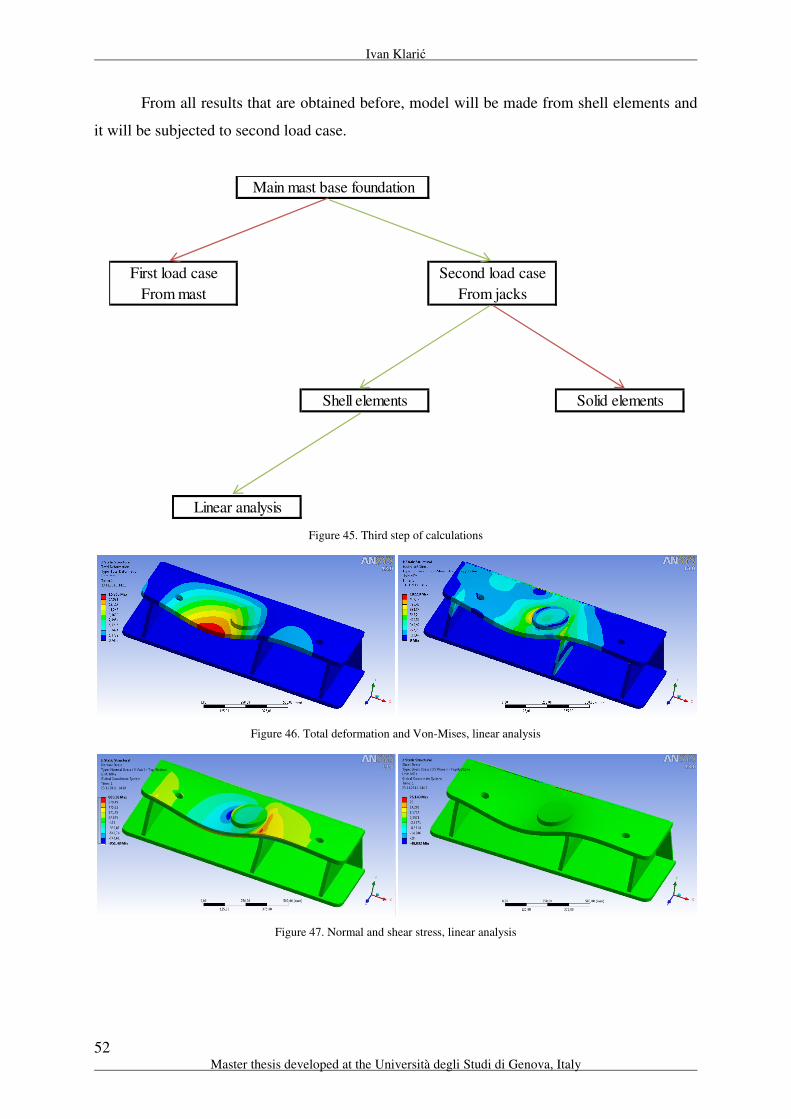
Ivan Klarić
52 Master thesis developed at the Università degli Studi di Genova, Italy
From all results that are obtained before, model will be made from shell elements and
it will be subjected to second load case.
Figure 45. Third step of calculations
Figure 46. Total deformation and Von-Mises, linear analysis
Figure 47. Normal and shear stress, linear analysis
Linear analysis
Solid elements
From mast From jacks
Shell elements
Main mast base foundation
First load case Second load case
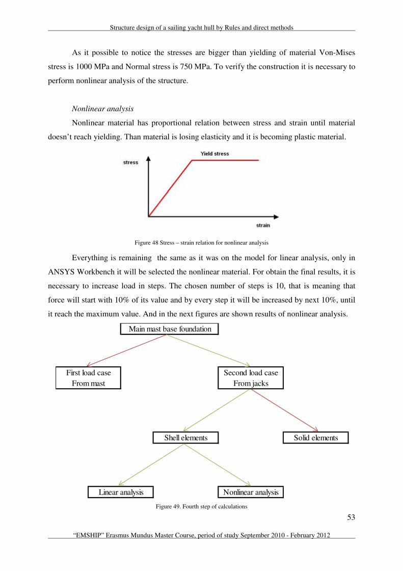
Structure design of a sailing yacht hull by Rules and direct methods
53
“EMSHIP” Erasmus Mundus Master Course, period of study September 2010 - February 2012
As it possible to notice the stresses are bigger than yielding of material Von-Mises
stress is 1000 MPa and Normal stress is 750 MPa. To verify the construction it is necessary to
perform nonlinear analysis of the structure.
Nonlinear analysis
Nonlinear material has proportional relation between stress and strain until material
doesn’t reach yielding. Than material is losing elasticity and it is becoming plastic material.
Figure 48 Stress – strain relation for nonlinear analysis
Everything is remaining the same as it was on the model for linear analysis, only in
ANSYS Workbench it will be selected the nonlinear material. For obtain the final results, it is
necessary to increase load in steps. The chosen number of steps is 10, that is meaning that
force will start with 10% of its value and by every step it will be increased by next 10%, until
it reach the maximum value. And in the next figures are shown results of nonlinear analysis.
Figure 49. Fourth step of calculations
Linear analysis
Solid elements
Nonlinear analysis
From mast From jacks
Shell elements
Main mast base foundation
First load case Second load case

Ivan Klarić
54 Master thesis developed at the Università degli Studi di Genova, Italy
Figure 50. Nonlinear analysis, convergence of the results
Graph of convergence doesn’t look like typical graphs of convergence. However
convergence is reached. How does ANSYS work in this situation, it start with 10% of the
force, and when the force convergence (pink line) go under the force criterion (light blue line)
that means that convergence for that 10% of the force is reached and now force will be
increased with next 10% (green line). It is possible to notice that on the graph, there are nine
green lines and that is exactly 100% of the force, if it was started with 10% and each step was
10% more. Also on the graph there are two places where bisection was occurred (red line),
that meaning the force couldn’t reach the convergence and on the place like that, value of the
force will go back 10% to the previous value and step of increasing for next convergence will
be 5% instead of the 10%.
Figure 51. Total deformation and Von-Mises stress, nonlinear analysis
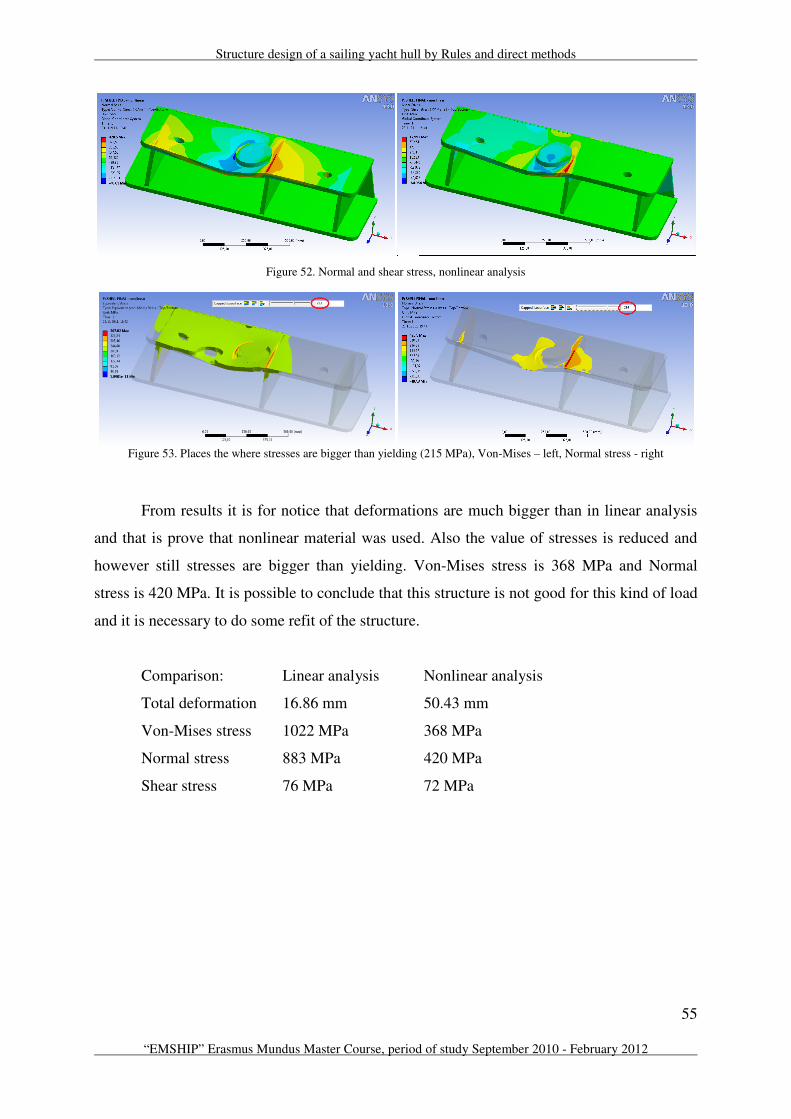
Structure design of a sailing yacht hull by Rules and direct methods
55
“EMSHIP” Erasmus Mundus Master Course, period of study September 2010 - February 2012
Figure 52. Normal and shear stress, nonlinear analysis
Figure 53. Places the where stresses are bigger than yielding (215 MPa), Von-Mises – left, Normal stress - right
From results it is for notice that deformations are much bigger than in linear analysis
and that is prove that nonlinear material was used. Also the value of stresses is reduced and
however still stresses are bigger than yielding. Von-Mises stress is 368 MPa and Normal
stress is 420 MPa. It is possible to conclude that this structure is not good for this kind of load
and it is necessary to do some refit of the structure.
Comparison: Linear analysis Nonlinear analysis
Total deformation 16.86 mm 50.43 mm
Von-Mises stress 1022 MPa 368 MPa
Normal stress 883 MPa 420 MPa
Shear stress 76 MPa 72 MPa

Ivan Klarić
56 Master thesis developed at the Università degli Studi di Genova, Italy
5.1.4. Solution of the problem, for existing structure
For existing structure additional bracket will be added under the most critical area,
where the load acts on the structure. Different position of the bracket will be investigated.
Figure 54. Total deformation of the structure with additional bracket in different positions
Figure 55. Von-Mises stress of the structure with additional bracket in different positions
Figure 56. Normal stress of the structure with additional bracket in different positions
Exact position of additional bracket is checked with few models and the best position
is selected. Notice that bracket will be moved from middle to the side where are the biggest
deformations.
Position of the bracket Deformation Von-Mises Normal stress
In the middle 1,401 mm 218 MPa 139 MPa
15 mm from the middle 0,842 mm 182 MPa 122 MPa
20 mm from the middle 0,725 mm 169 MPa 142 MPa
25 mm from the middle 0,627 mm 160 MPa 160 MPa
30 mm from the middle 0,550 mm 169 MPa 177 MPa
50 mm from the middle 0,677 mm 233 MPa 235 MPa
All of these models were made from shell elements, and influence of bottom plate was
neglected. Fixed constraint was applied on the bottom plate and that constraint forbids the
movement of mesh in any direction. Now for the final model it is necessary to check influence
of additional piece bracket and construction below bottom plate. On this model additional
piece will have next dimension: 200x200x275. This kind of piece will be verified for the
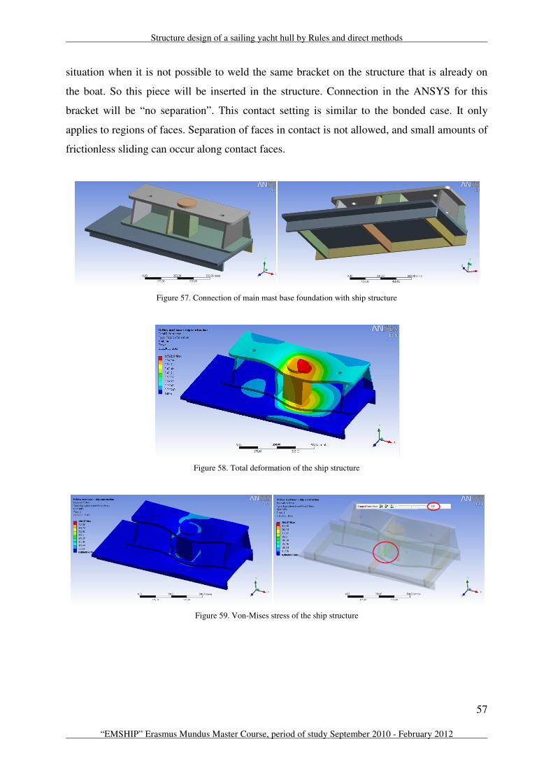
Structure design of a sailing yacht hull by Rules and direct methods
57
“EMSHIP” Erasmus Mundus Master Course, period of study September 2010 - February 2012
situation when it is not possible to weld the same bracket on the structure that is already on
the boat. So this piece will be inserted in the structure. Connection in the ANSYS for this
bracket will be “no separation”. This contact setting is similar to the bonded case. It only
applies to regions of faces. Separation of faces in contact is not allowed, and small amounts of
frictionless sliding can occur along contact faces.
Figure 57. Connection of main mast base foundation with ship structure
Figure 58. Total deformation of the ship structure
Figure 59. Von-Mises stress of the ship structure
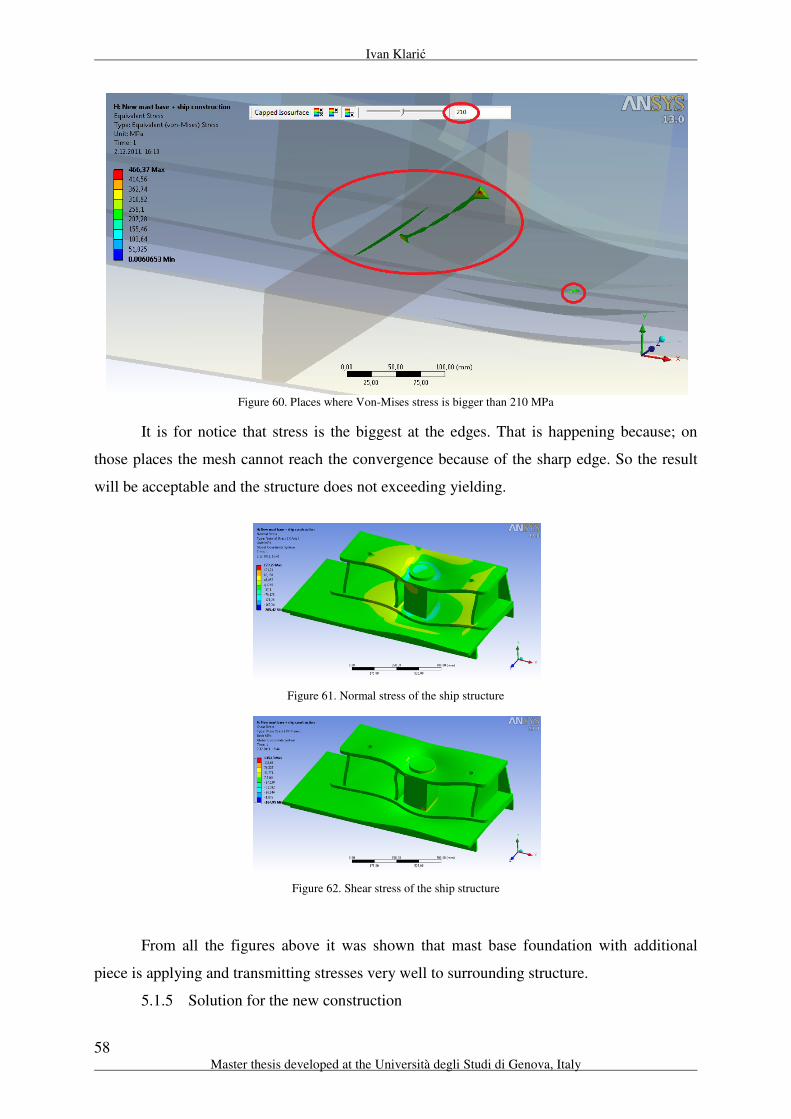
Ivan Klarić
58 Master thesis developed at the Università degli Studi di Genova, Italy
Figure 60. Places where Von-Mises stress is bigger than 210 MPa
It is for notice that stress is the biggest at the edges. That is happening because; on
those places the mesh cannot reach the convergence because of the sharp edge. So the result
will be acceptable and the structure does not exceeding yielding.
Figure 61. Normal stress of the ship structure
Figure 62. Shear stress of the ship structure
From all the figures above it was shown that mast base foundation with additional
piece is applying and transmitting stresses very well to surrounding structure.
5.1.5 Solution for the new construction

Structure design of a sailing yacht hull by Rules and direct methods
59
“EMSHIP” Erasmus Mundus Master Course, period of study September 2010 - February 2012
In this case, middle bracket will be moved to the centre of plate and it will be verified
does it is possible to withstand to the load acting from the jack.
Figure 63. Total deformation, new construction
Figure 64. Von-Mises stress, new construction
Figure 65. Normal stresses, new construction
New construction:
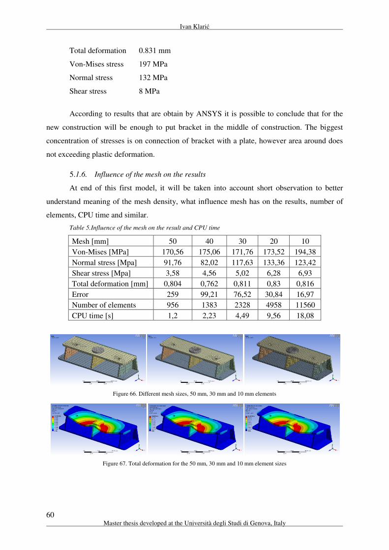
Ivan Klarić
60 Master thesis developed at the Università degli Studi di Genova, Italy
Total deformation 0.831 mm
Von-Mises stress 197 MPa
Normal stress 132 MPa
Shear stress 8 MPa
According to results that are obtain by ANSYS it is possible to conclude that for the
new construction will be enough to put bracket in the middle of construction. The biggest
concentration of stresses is on connection of bracket with a plate, however area around does
not exceeding plastic deformation.
5.1.6. Influence of the mesh on the results
At end of this first model, it will be taken into account short observation to better
understand meaning of the mesh density, what influence mesh has on the results, number of
elements, CPU time and similar.
Table 5.Influence of the mesh on the result and CPU time
Mesh [mm] 50 40 30 20 10
Von-Mises [MPa] 170,56 175,06 171,76 173,52 194,38
Normal stress [Mpa] 91,76 82,02 117,63 133,36 123,42
Shear stress [Mpa] 3,58 4,56 5,02 6,28 6,93
Total deformation [mm] 0,804 0,762 0,811 0,83 0,816
Error 259 99,21 76,52 30,84 16,97
Number of elements 956 1383 2328 4958 11560
CPU time [s] 1,2 2,23 4,49 9,56 18,08
Figure 66. Different mesh sizes, 50 mm, 30 mm and 10 mm elements
Figure 67. Total deformation for the 50 mm, 30 mm and 10 mm element sizes

Structure design of a sailing yacht hull by Rules and direct methods
61
“EMSHIP” Erasmus Mundus Master Course, period of study September 2010 - February 2012
Figure 68. Number of elements vs mesh size
Figure 69. CPU time vs mesh size
Figure 70. CPU time vs number of elements
0
2000
4000
6000
8000
10000
12000
14000
101520253035404550
Num
ber
of
elem
ents
Mesh size [mm]
Number of elements vs mesh size
0
4
8
12
16
20
101520253035404550
CP
U t
ime
[s]
Mesh size [mm]
CPU time vs mesh size
0
2
4
6
8
10
12
14
16
18
20
0 2000 4000 6000 8000 10000 12000 14000
CP
U t
ime
[s]
Number of elements
CPU time vs number of elements
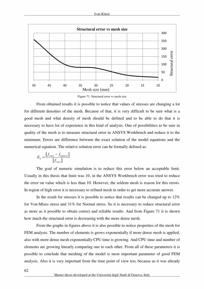
Ivan Klarić
62 Master thesis developed at the Università degli Studi di Genova, Italy
Figure 71. Structural error vs mesh size
From obtained results it is possible to notice that values of stresses are changing a lot
for different densities of the mesh. Because of that, it is very difficult to be sure what is a
good mesh and what density of mesh should be defined and to be able to do that it is
necessary to have lot of experience in this kind of analysis. One of possibilities to be sure in
quality of the mesh is to measure structural error in ANSYS Workbench and reduce it to the
minimum. Errors are difference between the exact solution of the model equations and the
numerical equation. The relative solution error can be formally defined as:
exact numeric
S
exact
f fE
f
−=
The goal of numeric simulation is to reduce this error below an acceptable limit.
Usually in this thesis that limit was 10, in the ANSYS Workbench error was tried to reduce
the error on value which is less than 10. However, the seldom mesh is reason for this errors.
In region of high error it is necessary to refined mesh in order to get more accurate answer.
In the result for stresses it is possible to notice that results can be changed up to 12%
for Von-Mises stress and 31% for Normal stress. So it is necessary to reduce structural error
as more as it possible to obtain correct and reliable results. And from Figure 71 it is shown
how much the structural error is decreasing with the more dense mesh.
From the graphs in figures above it is also possible to notice properties of the mesh for
FEM analysis. The number of elements is grows exponentially if more dense mesh is applied,
also with more dense mesh exponentially CPU time is growing. And CPU time and number of
elements are growing linearly comparing one to each other. From all of these parameters it is
possible to conclude that meshing of the model is most important parameter of good FEM
analysis. Also it is very important from the time point of view too, because as it was already
0
50
100
150
200
250
300
101520253035404550
Str
uct
ura
l er
ror
Mesh size [mm]
Structural error vs mesh size
Structure design of a sailing yacht hull by Rules and direct methods
63
“EMSHIP” Erasmus Mundus Master Course, period of study September 2010 - February 2012
mention that CPU time is growing exponentially with more dense mesh. To obtain good mesh
and still not so time consummating to perform numerical analysis is very challenging very
important task of each engineers.
Short summary of this project; in the project it was performed static finite element
analysis of the main mast base foundation. It was necessary to check the structure on two load
cases, main load from the mast and secondary load case from the jacks. The main goal was to
see where the critical areas are for that loads on the existing structure, solve the problem if it
exist and offer the solution for the new structure.
The most of models were done by shell elements because of the good results that are
obtained compared by solid elements and also they need less CPU time to perform same
simulation. For complicated models like connection of main mast base foundation with ship
structure, solid elements were used.
With linear and nonlinear analysis it was shown that existing construction doesn’t
satisfy for this kind of loads, the some parts of structure exceed the elastic area and go to the
plastic area. Solution for existing structure is to add a piece of aluminium and put it under the
jacks to hold the deformation and translate the stresses to the lower part of the structure. For
the new structure it is necessary to move the bracket in the middle and that construction is
able to resist on that loads.
5.2. Keel – Hull Structure Connection
In this project it will be performed static finite element method analysis of the keel –
hull structure connection. The type of the keel is swing keel. Swing keel is keel that can be
pulled up (rotational movement) in the hull when yacht is cruising with the engines to reduce
the resistance of the yacht or when yacht is coming to the port to reduce the draft, however
when is using the sails keel is needed to make contra moment for the sails. This keel is
rotating around fixed point, and there are some solutions where it is possible just to pull up
and then to push back vertically the keel [7]. How the loads should be considered, the first
step is to consult the classification society rules. Keel and hull structure will be verified
according to the American Bureau of Shipping – Guide for Building and Classing Offshore
Racing Yachts.

Ivan Klarić
64 Master thesis developed at the Università degli Studi di Genova, Italy
According to the rules:
9.13.1 Continuity
Where fitted, floors within ballast keels and in spacer structure between the ballast
keel and the underside of the hull are to be in line with the floors in the hull. Internal load
carrying members within the ballast keel are to be aligned and connected with floors in
adjacent structure.
9.13.3 Structure
The shear and primary stresses at any location of the keel structure under the following
assumed load are not to exceed the respective allowable stresses given below.
Assumed Load:
Acting Transversely – weight of the keel below the section of the keel under
consideration acting at its centre of gravity
Allowable stress: Shear stress Primary stress
All materials: 0.5y
τ
Where:
Minimum tensile strength of the material, it is not to be taken as greater than
70% of the ultimate tensile strength of the material.
Minimum shear yield strength of the material, it is not to be taken as greater
the 40% of the ultimate tensile strength of the material.
From the rules only one load case that will be applied on the structure is weight of the
keel, or its own gravity.
Material of the keel and structure is aluminium magnesium alloy 5083 H321. And
main characteristics of this alloy are:
0.5 yσ
=y
σ
=y
τ
3
kg2660 - density
mρ =
Tensile Yield Strenght - 215 MPa
Compressive Yield Strenght - 215 MPa
Tensile Ultimate Strenght - 305 MPa
Young's modulus - 71000 MPa
Poisson's ration - 0.33
Structure design of a sailing yacht hull by Rules and direct methods
65
“EMSHIP” Erasmus Mundus Master Course, period of study September 2010 - February 2012
When keel is built, it is necessary to fulfil the keel with material to obtain bigger mass
of the keel. In Perini Navi shipyard material that is used for fulfil the keel is lead. Lead is a
bluish white lustrous metal. It is very soft, highly malleable, ductile and a relatively poor
conductor of electricity. It is very resistant to corrosion, but tarnishes upon exposure to air.
Lead has very big density, it can give big mass for small area and also it have almost twice
time less melting point of aluminium so it is possible to put the lead inside of the keel in
liquid phase. The lead has next main characteristics:
Chemical symbol Pb
Density 11.34 t/m3 at 20
oC
Melting point 327 oC (melting point of Aluminium is 660.37
oC)
5.2.1. Model of the keel – structure connection
Model will be divided in two parts. One part is a structure of the keel and second one
is structure of the hull. Connection between them is with the pin. Model was separated
because to simulate pin connection is very difficult. That is meaning, that two analysis should
be performed. In first keel will be submitted to its own gravity and in second the forces will
be measured at places where keel is connected with the structure and those forces will be
transmitted to the structure of the yacht. Models are possible to see on the Figure 73 and
Figure 75. Models are modelled by surfaces because finite element method will be performed
by shell elements. There are two reasons to do that by shell elements. First is to safe CPU
time and to perform analysis much faster, as we obtain from the previous model. And second
one is that model has very big dimensions and if it is meshed by solid element it is necessary
to mesh with bigger number of elements to obtain good results. Why is so complicated to do
that in solids, because, to obtain good results when plate is deforming, it is necessary to put
minimum two or three solid element in thickness to obtain good values of compression and
tension of the plate, however for shell it is enough only one element for good results. As
ANSYS is limited to 300 000 elements, with solids it is not possible to mesh the structure to
obtain accurate results until that number of elements. Mesh of the keel structure with shell
elements already has 127 000 elements.

Ivan Klarić
66 Master thesis developed at the Università degli Studi di Genova, Italy
Figure 72. 2-D drawing of the keel from Perini-Navi (left), 3-D model of the keel made in SolidWorks (right)
Figure 73. 3-D model of the keel structure
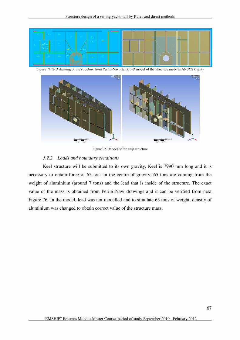
Structure design of a sailing yacht hull by Rules and direct methods
67
“EMSHIP” Erasmus Mundus Master Course, period of study September 2010 - February 2012
Figure 74. 2-D drawing of the structure from Perini-Navi (left), 3-D model of the structure made in ANSYS (right)
Figure 75. Model of the ship structure
5.2.2. Loads and boundary conditions
Keel structure will be submitted to its own gravity. Keel is 7990 mm long and it is
necessary to obtain force of 65 tons in the centre of gravity; 65 tons are coming from the
weight of aluminium (around 7 tons) and the lead that is inside of the structure. The exact
value of the mass is obtained from Perini Navi drawings and it can be verified from next
Figure 76. In the model, lead was not modelled and to simulate 65 tons of weight, density of
aluminium was changed to obtain correct value of the structure mass.

Ivan Klarić
68 Master thesis developed at the Università degli Studi di Genova, Italy
Figure 76. Total mass that acts in cetner of gravity
The structure will be restrained and constrain the degrees of freedom to make the
model behave in a realistic manner. As it mentioned before, there are six degrees of the
freedom to consider, three translations and three rotations. Boundary conditions are; three
displacement support, two in z direction (direction in which the centre of gravity is acting),
one in y direction and one compressions only support. First and second displacement supports
are coming from bearing head (A – z direction and D – y direction, on the Figure 78) which is
placed around pin and his purpose is also to protect vertically movement of the keel. Third
displacement support is coming from the plate (B on the Figure 78) and it also restricts the
movement of the keel. And compressions only support is used to simulate connection with the
pin (C on the Figure 78).
Figure 77. Boundary conditions and centre of gravity
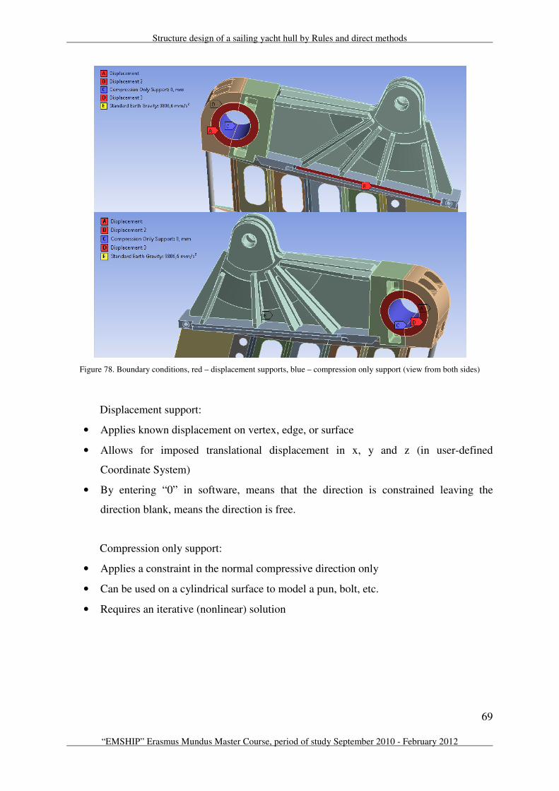
Structure design of a sailing yacht hull by Rules and direct methods
69
“EMSHIP” Erasmus Mundus Master Course, period of study September 2010 - February 2012
Figure 78. Boundary conditions, red – displacement supports, blue – compression only support (view from both sides)
Displacement support:
• Applies known displacement on vertex, edge, or surface
• Allows for imposed translational displacement in x, y and z (in user-defined
Coordinate System)
• By entering “0” in software, means that the direction is constrained leaving the
direction blank, means the direction is free.
Compression only support:
• Applies a constraint in the normal compressive direction only
• Can be used on a cylindrical surface to model a pun, bolt, etc.
• Requires an iterative (nonlinear) solution
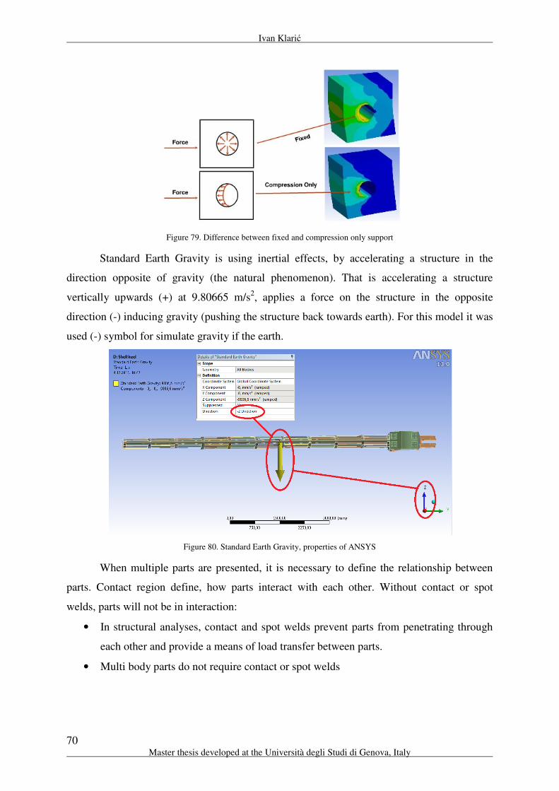
Ivan Klarić
70 Master thesis developed at the Università degli Studi di Genova, Italy
Figure 79. Difference between fixed and compression only support
Standard Earth Gravity is using inertial effects, by accelerating a structure in the
direction opposite of gravity (the natural phenomenon). That is accelerating a structure
vertically upwards (+) at 9.80665 m/s2, applies a force on the structure in the opposite
direction (-) inducing gravity (pushing the structure back towards earth). For this model it was
used (-) symbol for simulate gravity if the earth.
Figure 80. Standard Earth Gravity, properties of ANSYS
When multiple parts are presented, it is necessary to define the relationship between
parts. Contact region define, how parts interact with each other. Without contact or spot
welds, parts will not be in interaction:
• In structural analyses, contact and spot welds prevent parts from penetrating through
each other and provide a means of load transfer between parts.
• Multi body parts do not require contact or spot welds

Structure design of a sailing yacht hull by Rules and direct methods
71
“EMSHIP” Erasmus Mundus Master Course, period of study September 2010 - February 2012
Figure 81. Example of the bonded connection in ANSYS
All connections of the keel between surfaces are bonded connection. Bonded
connection is the default configuration for contact regions. If contact regions are bonded, then
no sliding or separation between faces or edges is allowed. Think of the region as glued. This
type of contact allows for a linear solution since the contact length/area will not change during
the application of the load. If contact is determined on the mathematical model, any gaps will
be closed and any initial penetration will be ignored.
All connections are set up in ANSYS, even if assembly was done in SolidWorks.
ANSYS can recognize connection of the solids, but for the surfaces it has a problems, so to be
sure in the structure connection, all the connections has been done one by one in ANSYS and
every time connection was verified to view the model deflection. This was showing does
every of the nodes are properly connected and also does model is behaving as expected. This
was very important step in keel modelling, because model from SolidWorks is looking like
connected model, however if they don’t share common node, then they are not
mathematically connected and model will not be solved correctly.
After analysis is performed it is necessary to set up the probes in each support. All
probes are measuring force reaction.
Force reaction for the bearing head (in direction of centre of gravity):
733.8 kNaxis
z =
Force reaction for the bearing head (opposite direction of centre of gravity):
2615 kNaxis
y =

Ivan Klarić
72 Master thesis developed at the Università degli Studi di Genova, Italy
Force reaction for the plate:
1359 kNaxis
z =
Force reaction for the pin:
9.71 kNaxis
x =
2572 kN
axisy = −
3.1 kN
axisz = −
Total 2572 kN=
This force reaction will be input parameters for the yacht structure. So there it will be
two different load cases, for two sides of structure. At one side load will be force reaction of
the pin + force reaction of the bearing load at opposite direction from the centre of gravity and
on other side it will be force reaction of the pin + force reaction of the bearing load at
direction of the centre of gravity.
Sum of those vectors is:
Force reaction of the pin + Force reaction of the bearing load in direction of the centre
of gravity:
9.71 kNaxis
x =
2572 kN
axisy = −
730.7 kN
axisz =
Total 2673 kN=
Force reaction of the pin + Force reaction of the bearing load in direction of the centre
of gravity:
9.71 kNaxis
x =
43 kN
axisy =
3.1 kN
axisz = −
Total 44.2 kN=
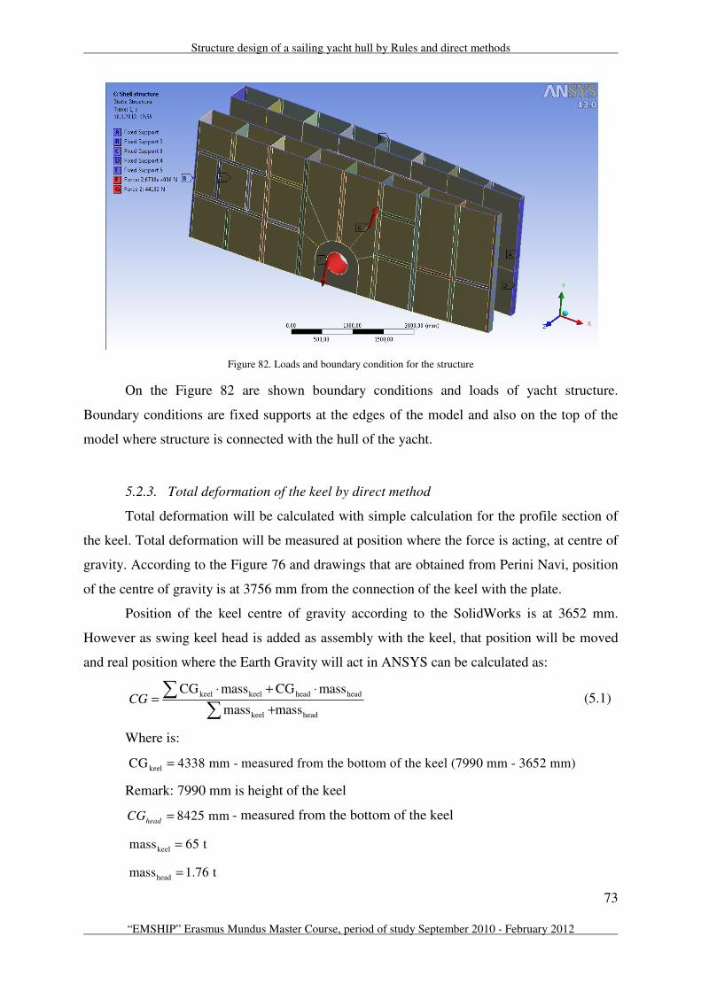
Structure design of a sailing yacht hull by Rules and direct methods
73
“EMSHIP” Erasmus Mundus Master Course, period of study September 2010 - February 2012
Figure 82. Loads and boundary condition for the structure
On the Figure 82 are shown boundary conditions and loads of yacht structure.
Boundary conditions are fixed supports at the edges of the model and also on the top of the
model where structure is connected with the hull of the yacht.
5.2.3. Total deformation of the keel by direct method
Total deformation will be calculated with simple calculation for the profile section of
the keel. Total deformation will be measured at position where the force is acting, at centre of
gravity. According to the Figure 76 and drawings that are obtained from Perini Navi, position
of the centre of gravity is at 3756 mm from the connection of the keel with the plate.
Position of the keel centre of gravity according to the SolidWorks is at 3652 mm.
However as swing keel head is added as assembly with the keel, that position will be moved
and real position where the Earth Gravity will act in ANSYS can be calculated as:
(5.1)
Where is:
Remark: 7990 mm is height of the keel
8425 mmheadCG = - measured from the bottom of the keel
keel keel head head
keel head
CG mass CG mass
mass massCG
⋅ + ⋅=
+
∑∑
keelCG 4338 mm - measured from the bottom of the keel (7990 mm - 3652 mm)=
keelmass 65 t =
headmass 1.76 t =

Ivan Klarić
74 Master thesis developed at the Università degli Studi di Genova, Italy
4446 mmCG = - from the bottom
3544 mmCG = - from the connection of the keel and swing keel head
Real centre of gravity is at 3756 mm from the connection and one that is obtained with
software and calculation is 3544 mm. So the difference between them is 212 mm, on 7990
mm long keel, and that is acceptable. From modelling point of view it was very difficult to
model shape of the keel 100% equal as it in reality and small difference between those two
values was expected.
The section that was modelled is shown in next Figure 83:
Figure 83. Section of the keel from SolidWorks (up) and Perini Navi (down)
Section was done at SolidWorks and from the same software next informations about
section are obtained:
According to the beam theory:
Figure 84. Console with force acting at end of the console
(5.2)
43220628979 mmI =
2204731 mmA =
3
where is:3
FL
EIδ =

Structure design of a sailing yacht hull by Rules and direct methods
75
“EMSHIP” Erasmus Mundus Master Course, period of study September 2010 - February 2012
41.38 mmδ =
Stresses along the beam are calculated as:
M z
Iσ
⋅= (5.3)
M F x= ⋅
195 mmz =
Table 6. Stresses of the keel according to the direct method
x [m] 3544 3344 3144 2944 2744 2544
M [Nmm] 2259831600 2132301600 2004771600 1877241600 1749711600 1622181600
σ [N/mm2] 136,83 129,10 121,38 113,66 105,94 98,22
x [m] 2344 2144 1944 1744 1544 1344
M [Nmm] 1494651600 1367121600 1239591600 1112061600 984531600 857001600
σ [N/mm2] 90,50 82,78 75,05 67,33 59,61 51,89
x [m] 1144 944 744 544 344 144
M [Nmm] 729471600 601941600 474411600 346881600 219351600 91821600
σ [N/mm2] 44,17 36,45 28,72 21,00 13,28 5,56
Where the biggest value of x is at place where console is connected with the wall and
the lowest value is close to the acting of the force. Stress at connection of the keel with the
swing keel head is 137 N/mm2 or MPa.
5.2.4. Total deformation of the keel and the structure
To be sure in FEM analysis, does it gives good results and that are boundary condition
very well chosen for this model, it is necessary to compare the results between direct method
and numerical simulation. From direct method values of the stresses and total deformation at
the centre of gravity are obtained, those two values will be compared.
65000 kgM =
637650 NF =
2
N71000
mmE =
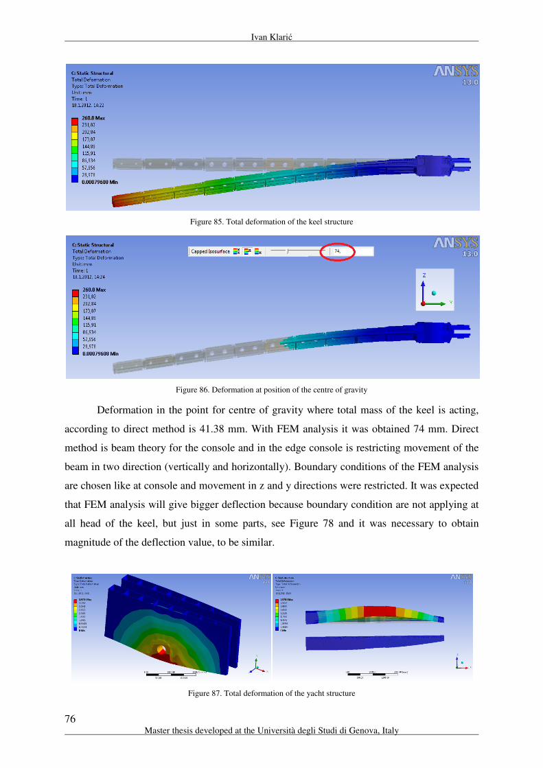
Ivan Klarić
76 Master thesis developed at the Università degli Studi di Genova, Italy
Figure 85. Total deformation of the keel structure
Figure 86. Deformation at position of the centre of gravity
Deformation in the point for centre of gravity where total mass of the keel is acting,
according to direct method is 41.38 mm. With FEM analysis it was obtained 74 mm. Direct
method is beam theory for the console and in the edge console is restricting movement of the
beam in two direction (vertically and horizontally). Boundary conditions of the FEM analysis
are chosen like at console and movement in z and y directions were restricted. It was expected
that FEM analysis will give bigger deflection because boundary condition are not applying at
all head of the keel, but just in some parts, see Figure 78 and it was necessary to obtain
magnitude of the deflection value, to be similar.
Figure 87. Total deformation of the yacht structure

Structure design of a sailing yacht hull by Rules and direct methods
77
“EMSHIP” Erasmus Mundus Master Course, period of study September 2010 - February 2012
For the structure maximum deflection is less than 4 mm. That is mainly because the
structure is very well and rough dimensioned. Just to obtain feeling about that, it is enough to
say that thickness of the plates is 50 mm, where is connection of the pin with the structure.
Deflection of the keel is high and for the structure is low, and compared with stresses
rules are satisfied and the deflections are acceptable. The values are shown on next Figure 88.
Figure 88. Values of stress at connection of the keel structure with keel head
With direct calculation obtained stress was 137 MPa and from the figure above it is
possible to see values of the stresses from the FEM analysis. Stresses are similar to direct
calculation and results are good. Some area are bigger than 105 MPa what was the demanding
from the classification society, and results will be acceptable because in reality this structure
is welded one to each other and in this model at this position are sharp edge and that is leading
again to the increasing of the stresses.
To be sure in obtained results it is necessary to verify structural error of the keel and
the structure, Structural error should be less than 10. In next Figure 89 and Figure 90,
structural error is shown. The biggest errors are happening were boundary conditions and the
sharp edges are.

Ivan Klarić
78 Master thesis developed at the Università degli Studi di Genova, Italy
Figure 89. Structural error of the keel
Figure 90. Structural error of the yacht structure
After the all model is properly set up, it is possible to proceed for the further analysis
of the results.

Structure design of a sailing yacht hull by Rules and direct methods
79
“EMSHIP” Erasmus Mundus Master Course, period of study September 2010 - February 2012
5.2.5. Von-Mises stress
Figure 91. Von-Mises stress of the keel structure
Figure 92. View of the connection swing keel head with structural blade for Von-Mises stress
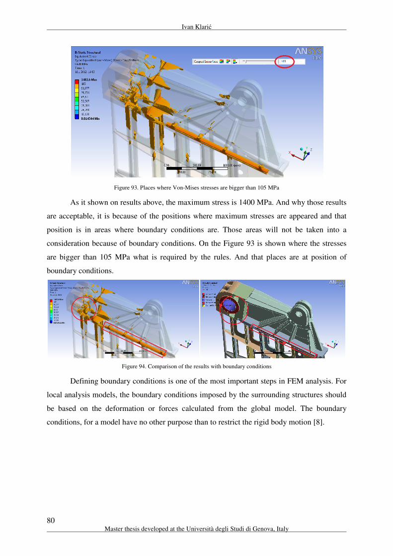
Ivan Klarić
80 Master thesis developed at the Università degli Studi di Genova, Italy
Figure 93. Places where Von-Mises stresses are bigger than 105 MPa
As it shown on results above, the maximum stress is 1400 MPa. And why those results
are acceptable, it is because of the positions where maximum stresses are appeared and that
position is in areas where boundary conditions are. Those areas will not be taken into a
consideration because of boundary conditions. On the Figure 93 is shown where the stresses
are bigger than 105 MPa what is required by the rules. And that places are at position of
boundary conditions.
Figure 94. Comparison of the results with boundary conditions
Defining boundary conditions is one of the most important steps in FEM analysis. For
local analysis models, the boundary conditions imposed by the surrounding structures should
be based on the deformation or forces calculated from the global model. The boundary
conditions, for a model have no other purpose than to restrict the rigid body motion [8].
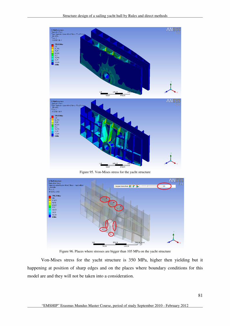
Structure design of a sailing yacht hull by Rules and direct methods
81
“EMSHIP” Erasmus Mundus Master Course, period of study September 2010 - February 2012
Figure 95. Von-Mises stress for the yacht structure
Figure 96. Places where stresses are bigger than 105 MPa on the yacht structure
Von-Mises stress for the yacht structure is 350 MPa, higher then yielding but it
happening at position of sharp edges and on the places where boundary conditions for this
model are and they will not be taken into a consideration.

Ivan Klarić
82 Master thesis developed at the Università degli Studi di Genova, Italy
5.2.6. Normal stress
Figure 97. Normal stress of the keel structure
Figure 98. View of the connection swing keel head with structural blade for Normal stress

Structure design of a sailing yacht hull by Rules and direct methods
83
“EMSHIP” Erasmus Mundus Master Course, period of study September 2010 - February 2012
Figure 99. Places where Normal stresses are bigger than 105 MPa
Figure 100. Normal stress for the yacht structure
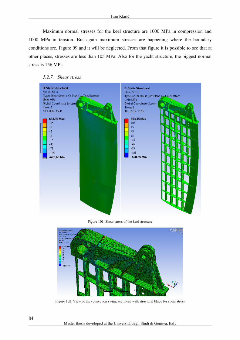
Ivan Klarić
84 Master thesis developed at the Università degli Studi di Genova, Italy
Maximum normal stresses for the keel structure are 1000 MPa in compression and
1000 MPa in tension. But again maximum stresses are happening where the boundary
conditions are, Figure 99 and it will be neglected. From that figure it is possible to see that at
other places, stresses are less than 105 MPa. Also for the yacht structure, the biggest normal
stress is 156 MPa.
5.2.7. Shear stress
Figure 101. Shear stress of the keel structure
Figure 102. View of the connection swing keel head with structural blade for shear stress
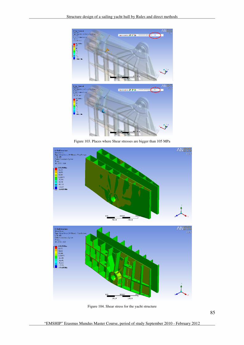
Structure design of a sailing yacht hull by Rules and direct methods
85
“EMSHIP” Erasmus Mundus Master Course, period of study September 2010 - February 2012
Figure 103. Places where Shear stresses are bigger than 105 MPa
Figure 104. Shear stress for the yacht structure

Ivan Klarić
86 Master thesis developed at the Università degli Studi di Genova, Italy
Maximum shear stress for the keel structure is 654 MPa. And again maximum stresses
are happening where the boundary conditions are, Figure 103. From that figure it is possible
to see that at other places, stresses are less than 105 MPa. For the yacht structure, the biggest
shear stress is 155 MPa.
The keel – structure connection is very well design by Perini Navi shipyard and
according to analysis that has been performed, the structure satisfy requirements from the
rules. Model for FEM analysis with the chosen boundary conditions simulate reality and
results of the numerical analysis have been verified with very simple beam theory calculation
for the one section of the keel structure and according to it; the results of numerical analysis
are similar with theory.
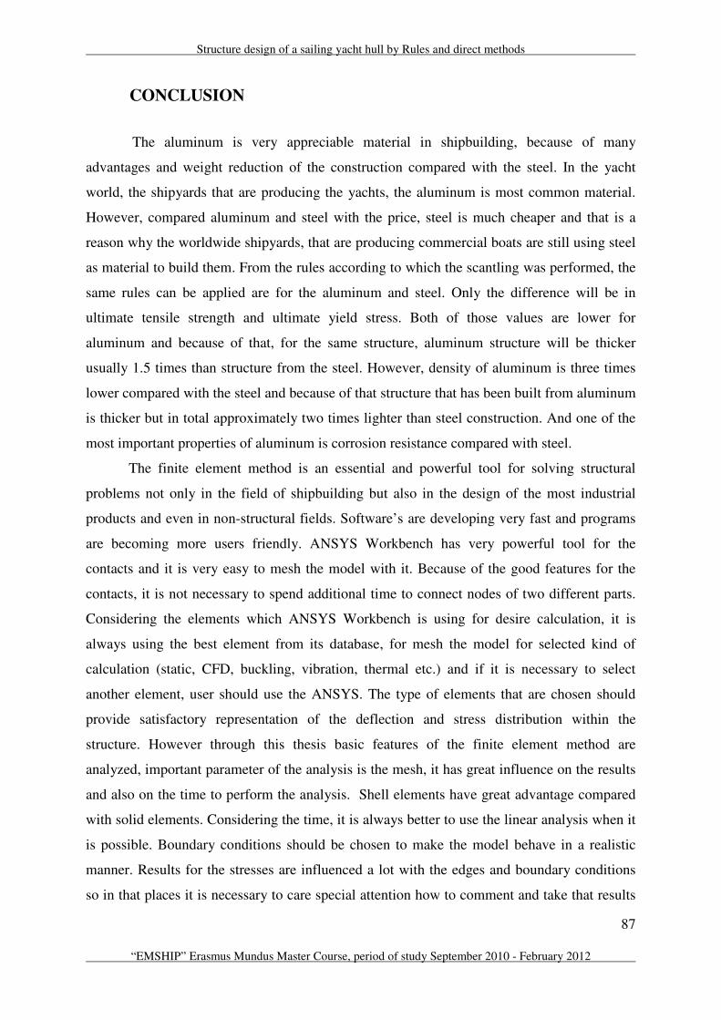
Structure design of a sailing yacht hull by Rules and direct methods
87
“EMSHIP” Erasmus Mundus Master Course, period of study September 2010 - February 2012
CONCLUSION
The aluminum is very appreciable material in shipbuilding, because of many
advantages and weight reduction of the construction compared with the steel. In the yacht
world, the shipyards that are producing the yachts, the aluminum is most common material.
However, compared aluminum and steel with the price, steel is much cheaper and that is a
reason why the worldwide shipyards, that are producing commercial boats are still using steel
as material to build them. From the rules according to which the scantling was performed, the
same rules can be applied are for the aluminum and steel. Only the difference will be in
ultimate tensile strength and ultimate yield stress. Both of those values are lower for
aluminum and because of that, for the same structure, aluminum structure will be thicker
usually 1.5 times than structure from the steel. However, density of aluminum is three times
lower compared with the steel and because of that structure that has been built from aluminum
is thicker but in total approximately two times lighter than steel construction. And one of the
most important properties of aluminum is corrosion resistance compared with steel.
The finite element method is an essential and powerful tool for solving structural
problems not only in the field of shipbuilding but also in the design of the most industrial
products and even in non-structural fields. Software’s are developing very fast and programs
are becoming more users friendly. ANSYS Workbench has very powerful tool for the
contacts and it is very easy to mesh the model with it. Because of the good features for the
contacts, it is not necessary to spend additional time to connect nodes of two different parts.
Considering the elements which ANSYS Workbench is using for desire calculation, it is
always using the best element from its database, for mesh the model for selected kind of
calculation (static, CFD, buckling, vibration, thermal etc.) and if it is necessary to select
another element, user should use the ANSYS. The type of elements that are chosen should
provide satisfactory representation of the deflection and stress distribution within the
structure. However through this thesis basic features of the finite element method are
analyzed, important parameter of the analysis is the mesh, it has great influence on the results
and also on the time to perform the analysis. Shell elements have great advantage compared
with solid elements. Considering the time, it is always better to use the linear analysis when it
is possible. Boundary conditions should be chosen to make the model behave in a realistic
manner. Results for the stresses are influenced a lot with the edges and boundary conditions
so in that places it is necessary to care special attention how to comment and take that results

Ivan Klarić
88 Master thesis developed at the Università degli Studi di Genova, Italy
into a consideration. The most important for the results analysis is experience of the engineer.
During structural dimensioning engineer should evaluate the results using different method to
let him to have an idea of the results. If strange results are obtained, engineer should check
something; he shouldn’t believe immediately the results coming from computer because
computer is an instrument for our work and it can’t substitute our knowledge and experience.
This thesis set up foundation of the finite element analysis with all explanations that
are necessary to understand FEM and this thesis can be very useful for the beginners in this
field. ANSYS Workbench in combination with SolidWorks, are very good tools for modelling
and performing this kind of numerical analysis. And results from numerical analysis are
having good coincidence with direct method calculation.

Structure design of a sailing yacht hull by Rules and direct methods
89
“EMSHIP” Erasmus Mundus Master Course, period of study September 2010 - February 2012
ACKNOWLEDGEMENTS
First I would like thank to prof. Philippe Rigo, coordinator of this Erasmus Mondus
program, for all what he done and what he still is doing for us.
To my coordinator in Italy, prof. Dario Boote, thank you for your time, support and
guidelines during the last semester in Italy.
It is a pleasure to thank those who made this thesis possible, especially to Franco
Torre, for his help and given possibilities to perform this thesis in Perini Navi shipyard, and
especially to my supervisor Stefano Baici, who encouraged, guided and supported me from
the initial to the final level of developing and understanding of this thesis.
A special thank is addressed to Audrey Mélotte, with her help all the bureaucracy of
the program seemed to be much easier.
I would like to thank to all professors and all universities, for the time and knowledge
that was given to us.
I am indebted to my many colleagues to support me during those three semesters and I
am happy that I found so many new friends during this program.
And for the end, I am indebted to thank to my family, they are my biggest support.

Ivan Klarić
90 Master thesis developed at the Università degli Studi di Genova, Italy
REFERENCES
[1] – Gardiner, R & Lavery, B – The Line of Battle: The Sailing Warship 1650-1840, 1992
(2004 edition), Conway, ISBN 0-85177-954-9
[2] – Sailing yacht design – 17th
International Ship and Offshore Structures Congress, August
2009, Seoul, Korea
[3] – American Bureau of Shipping – Guide for Building and Classing Offshore Racing
Yachts, 1994
[4] – Dave Garr – Boat Strength for Builders, Designers and Owners, 2000 International
marine, USA, ISBN 0-07-023159-1
[5] – Y. Okumoto, Y. Takeda, M. Mano and T. Okada – Design of Ship Hull Structures, 2009,
ISBN 978-3-540-88444-6
[6] – Perini – Navi shipyard – www.perininavi.it
[7] – Lars Larsson, Rolf E. Eliasson – Principles of Yacht Design – 2000 London, ISBN 0-
7136-5181-4
[8] – Yong Bai – Marine Structural Design – 2003 Oxford ISBN 0-08-043921-7

Structure design of a sailing yacht hull by Rules and direct methods
91
“EMSHIP” Erasmus Mundus Master Course, period of study September 2010 - February 2012
APPENDIX
