structurala analysis report
TRANSCRIPT

A
REPORT ON
STRUCTURAL DESIGN OF RESIDENTIAL BUILDING
Of
Ms. Kalpana Thapa
SUBMITTED TO:Kirtipur Municipality,Ward no-7, Kirtipur,
September, 2016

GENERAL
1.1 INTRODUCTION:This report is prepared on request from Ms. Kalpana Thapa to be submitted to Kirtipur Municipality as the partial requirement for the application for building construction permit. This Report describes in brief the Structural Aspects and Design Report of the proposed Residential Building at Tusal, Kirtipur.The building will be used for the residential purpose and will be designed for maximum of three and half story. The structural design is intended to be based primarily on the current Nepal Building Code of Practice.
1.2 STRUCTURAL SYSTEM FOR THE BUILDINGS
The structural system for the buildings have been evolved on the basis of various aspects like functional requirements of the building, durability and life span of building, cost effectiveness and other design criteria requirements specified by discussions on number of meetings with client.The buildings will be designed as a Ductile Moment Resisting Frame structure, meaning frames in which members and joints are capable of resisting forces primarily by flexure. The frames will be detailed to provide ductile behavior and comply with the requirements given in NBC 105.Element Sizes and DetailsInitially, for the purpose of load calculation following section will be assumedTypical floor height is 2.84m. And the floor height for the ground floor is 2.84 meter. Roof and Floor Slab = 125 mm thickStaircase slab = 150 mm thickBeams along Longitudinal direction = 230mm* 355mmBeams along traverse direction = 230 mm x 355 mm, Columns = 300 mm x 300 mmWall: - A 1 brick (230mm) and ½ brick (115mm) wall is used.
1.3 RELEVANT CODES FOLLOWED FOR DESIGN
The main design standards followed for structural design are given below, indicating their area of application.For Loading:NBC101-material specificationNBC102-unit weight of materialsNBC103-Imposed load
For Design of Reinforced Concrete:NBC105-seismic design of buildings in Nepal

1.4 COLUMN GRID PLAN WITH GRID NAMES AND CENTER LINE DIMENSIONS
1.6. DESIGN BASIS
1.6.1. GeneralThe reinforced concrete members are designed in accordance with Nepal Building Code. Other relevant codes as mentioned in the list above were also followed for specific items of work.Grade of Concrete and Cover to the ReinforcementThe appropriate grade of concrete and nominal cover to reinforcement is governed by the following main considerations:
• Durability of Concrete• Fire Resistance• Corrosion Protection to the Reinforcement• Bar Size• Nominal maximum aggregate size• Proposed Grade of Concrete & Cover to Reinforcement
Considering the nature of soil as observed in site during previous excavation for the site and the exposure conditions, fire rating, durability requirements etc. mentioned in NBC, the proposed grade of concrete for all the reinforced concrete members is M20, and clear cover to reinforcement for various items are as follows:
• Floor and plinth Beams 25mm• Columns & Pedestals 40mm• Slabs 20mm• Footings 50mm

1.6.2. MaterialsMaterials used as constituents of concrete shall be as per clause of NBC101. The properties of hardened concrete shall be as per NBC and other relevant clauses shall be considered. For 43 or 53 grade Ordinary Portland Cement conforming to NBC; gain of additional strength beyond 28 days is uncertain and thus age factor as indicated in NBC will not be considered.1.6.3 ReinforcementThe following types of reinforcement bars shall be used:1. Thermo-mechanically treated (TMT) Confirming to IS: 1786-1985 (fy = 500 MPa)2. Deformed bar Confirming to IS: 1786-1985 (fy = 415 MPa)Reinforcement Bars of size 8 mm, 10 mm, 12 mm, and 16mm will be used. Welded wire mesh shall not be used for structural members. Only lapped splices shall be used.1.6.4. AdmixturesThe concrete slump shall in general be in the range of 75mm and 125mm depending on reinforcement congestion, ambient temperature and other placement, transporting and compaction considerations. 1.6.5. Cement Use of blast furnace slag cement as per NBC is recommended for all elements of the structure constructed underground. The superstructure may have OPC cement conforming to NBC. 1.6.6 Structural DimensioningIn addition to the requirements of loads and stresses the minimum structural dimensions are also governed by other considerations like fire resistance, size of aggregates, reinforcement detailing, etc. Minimum width of beams & columns shall not be less than 250mm from above requirements.The minimum thickness of any structural element shall conform to NBC. The minimum thickness of various elements shall also meet the fire resistance requirements of IS: 8110-Part 1-1985. All the reinforced concrete elements of the building will be designed for mild condition of exposure and a fire resistance of 1.5 hours.The minimum thickness at the tip of strap footings shall be at least 200mm from the point of view of reinforcement detailing.The slope at top of the footings shall be not steeper than 1: 2.5 in order to obtain well compacted concrete throughout the footing.
LOAD CALULATION
A.DEAD LOAD CALCULATION
1. Unit Weight of materialsReinforced concrete = 25 KN/m3Brick masonary = 18.85 KN/m3Screed = 20.4 KN/m3Cement plaster = 20.4 KN/m3marble = 26.7 KN/m3
2. Floor LoadsThickness of structural slab = 0.125 mThickness of screed = 0.025 mThickness of celing plaster = 0.0125 mThickness of marble = 0.02 m
Dead Load of structural slab = 3.125 KN/m2
Dead Load of screed = 0.51 KN/m2

Dead Load of cement plaster = 0.255 KN/m2
Dead Load of marble = 0.534 KN/m2
Total dead load of floor finishes = 1.299 KN/m2
Dead load of partion walls = 1 KN/m2
Total dead load = 5.424 KN/m2
3. Heights of Beams, Walls & parapet wallsDepth of Beam in Longitudinal direction = 0.4 mDepth of Beam in transverse direction = 0.355 m
Height of each story of building = 3.2 mHeight of parapet wall = 1 m
4. Dead Loads of WallsDead load of 230mm thick wall in longitudinal direction = 12.14 KN/mdead load of side plaster of exterior wall(12.5mm+25mm)thick = 2.14
KN/m
Total dead load (Long. Dir.) = 14.28 KN/mDead load of 230mm thick wall in tranverse direction = 12.33 KN/mdead load of side plaster of exterior wall(12.5mm+25mm)thick = 2.18
KN/m
Total dead load (Traves. Dir.) = 14.51 KN/mDead load of 230mm thick wall with 30% in longitudinal direction = 10.00
KN/m
Dead load of 230mm thick wall with 30%in tranverse direction = 10.16
KN/m
Dead load of 115mm thick wall in long. Direction = 6.07 KN/mDead load of 115mm thick wall in trans. Direction = 6.17 KN/m
Dead load of parapet wall 4" thick = 2.16775 KN/m
B. Live Load Calculation
Live load in bedroom , living room = 2 KN/m2Live load in corridor, staircase, balconies = 3 KN/m2Roof live load access = 1.5 KN/m2roof live load not access = 0.75 KN/m2

Load Pattern DefinitionsName Type Self-Weight Multiplier Auto LoadSelf Dead 1Finishes Dead 04"wall Dead 09" wall with opening Dead 0Parapet wall Dead 0Staircase Dead 0roof live Live 0Floor live Live 0EQx Seismic 0 User CoefficientEQy Seismic 0 User CoefficientPartition Dead 09" wall Dead 0
1.7 Design and Detailing for Seismic ForcesCalculation of Lateral Seismic Load per NBC CodeA three dimensional modal analysis of the structure will be carried out using a Seismic Coefficient method. ETABS 2015 software will be used for analysis as well as the design of beam, column slab and isolated footings. The software has the capability to calculate seismic load as per the NBC specifications.Calculation of Seismic Weight of a frame:Seismic wt. at any floor level(Wi)= (Total Gravity Loads due to Beam, Column, lab, wall etc+25 %of live Load)Total Seismic Weight of the Frame, Wt=∑Wi ,Seismic weight of each story is calculated by ETABS 2015 on the basis of mass source parameter in which a factor of 1.00 has been assigned to the dead loads and a factor of 0.25 has been assigned to the live loads on floors except for the roof on which no live load will be considered for seismic load calculation as per codal provision.
1.7.1MethodologyThe design base shear is computed by ETABS 2015 in accordance with the NBC code
Mass source

NameInclude
Elements
Include Added Mass
Include Loads
Include Lateral
Include Vertical
Lump at Stories
IsDefaultLoad
PatternMultiplier
MsSrc1 False False True True False True True Self 1MsSrc1 False False True True False True True Finishes 1MsSrc1 False False True True False True True 4"wall 1
MsSrc1 False False True True False True True9" wall with opening
1
MsSrc1 False False True True False True TrueParapet wall
1
MsSrc1 False False True True False True True Staircase 1MsSrc1 False False True True False True True Floor live 0.25MsSrc1 False False True True False True True Partition 1MsSrc1 False False True True False True True 9" wall 1
MsSrc1 False False True True False True Trueweather shed
1
The seismic weight and base shear generated by ETABS2015 is shown below:
Load Pattern Type Direction Top Story Bottom Story C KWeight Used
kNBase Shear
kNEQx Seismic X slope 2 Base 0.08 1 4574.5784 365.9663EQy Seismic Y slope 2 Base 0.08 1 4574.5784 365.9663
1.8 Load Cases and Combinations used for analysisFollowing Load combinations are to be used as per clause 4.5 of NBC 105:1. 1.5*DL + 1.5*LL2. DL+1.3ll ±1.25EQ3. DL ±1.25EQ4. 0.9DL ±1.5EQ25% of LL as reduced live load RLL is to be considered when combined with EQ Load. Similarly, earthquake load is to be considered in two horizontal directions X and Y and in each direction, the load will be reversible, i.e. in +X and +Y directions.1.9 Control of DeflectionIn order to control deflection of structural elements, the criteria given in clause 23.2 of IS 456:2000 is proposed to be used.To control overall deformation due to earthquake load, the criteria given in clause 7.11 of IS 1893:2002 is applied.1.10 Control of CrackingIn order to avoid excessive cracking in the flexural members, maximum diameter and spacing of the reinforcement is restricted as per the detailing rules indicated in clause 26.0 IS: 456-2000.1.11 Masonry WallsMasonry walls have been treated as non-structural infill panels. Therefore, the structural safety of these walls is ensured by treating them as one way / two way slab panels spanning between adjoining beams and columns. These walls are designed as un-reinforced masonry as per` IS: 1905-1987 and IS: 4326-1993.

While external walls are provided with shear connector reinforcement on the underside of upper beams and sides of columns the internal partition walls are connected to roof slabs using dry packing mortar between top of walls and soffit of slab / beam.1.12 Site conditions:
• Soil Type : Gravel mixed soil• Allowable Bearing Capacity : 150 KN/sq m
1.13 Design procedure:• Adopt initial size of members on the basis of Architectural and serviceability
requirement. • Analysis the structure in design load.• Conform the section on deflection criteria.• Design for stresses• Conform with construction criteria
ANALYSIS PART
2.1 Design SoftwareA three dimensional analysis of the structure was carried out using a Seismic Coefficient method. ETABS2015 software was used for analysis of the model as well as the design of beam, column, slab element and foundation.
2.2 Output data resultsSome of the important sample output data are presented below:
2.2.1 BASE REACTIONS –(UNIT KN METER)
Load Case/ComboFXkN
FYkN
FZkN
MXkN-m
MYkN-m
MZkN-m
Xm
Ym
Zm
Dead 0 0 2442.4899 15763.0913 -16682.6092 0 0 0 0Finishes 0 0 564.3398 3642.0529 -3920.9003 0 0 0 04"wall 0 0 47.9532 473.1546 -308.2914 0 0 0 09" wall with opening 0 0 450.2609 2860.82 -3099.1103 0 0 0 0Parapet wall 0 0 159.8501 1067.3417 -1077.7011 0 0 0 0Staircase dead 0 0 304.8 1950.72 -1092.9518 0 0 0 0roof live 0 0 156.7739 994.7425 -1155.581 0 0 0 0Floor live 0 0 566.8187 3636.2371 -4016.4055 0 0 0 0EQx -365.9663 0 0 0 -2863.0317 2316.5772 0 0 0EQy 0 -365.9663 0 2863.0317 0 -2390.2694 0 0 0Partition 0 0 42.064 273.9169 -286.2312 0 0 0 09" wall 0 0 304.0135 1383.2796 -1896.8453 0 0 0 0weather shed 0 0 186.5613 1179.7262 -1312.4524 0 0 0 0

Load Case/ComboFXkN
FYkN
FZkN
MXkN-m
MYkN-m
MZkN-m
Xm
Ym
Zm
DL 0 0 4011.7579 26031.0974 -26467.7953 0 0 0 0LL 0 0 723.5926 4630.9796 -5171.9865 0 0 0 01.5(DL+LL) 0 0 7103.0258 45993.1155 -47459.6726 0 0 0 00.9dl+1.25EQx -457.4578 0 3610.5821 23427.9877 -27399.8053 2895.7215 0 0 00.9dl-1.25EQx 457.4578 0 3610.5821 23427.9877 -20242.2261 -2895.7215 0 0 00.9dl+1.25EQy 0 -457.4578 3610.5821 27006.7773 -23821.0157 -2987.8367 0 0 00.9dl-1.25EQy 0 457.4578 3610.5821 19849.1981 -23821.0157 2987.8367 0 0 0dl+1.25EQx -457.4578 0 4011.7579 26031.0974 -30046.5848 2895.7215 0 0 0dl-1.25EQx 457.4578 0 4011.7579 26031.0974 -22889.0057 -2895.7215 0 0 0dl+1.25EQy 0 -457.4578 4011.7579 29609.887 -26467.7953 -2987.8367 0 0 0dl-1.25EQy 0 457.4578 4011.7579 22452.3078 -26467.7953 2987.8367 0 0 0dl+1.3ll+1.25EQx -457.4578 0 4952.4283 32051.3709 -36770.1672 2895.7215 0 0 0dl+1.3ll-1.25EQx 457.4578 0 4952.4283 32051.3709 -29612.5881 -2895.7215 0 0 0dl+1.3ll-1.25EQy 0 457.4578 4952.4283 28472.5813 -33191.3777 2987.8367 0 0 0dl+1.3ll+1.25EQy 0 -457.4578 4952.4283 35630.1604 -33191.3777 -2987.8367 0 0 0
Sample design calculation
Concrete grade: M20Steel grade: Fe500Steel for stirrups: Fe415

Elevation along grid C-C

Elevation along grid 2-2
DESIGN OF SLABS
Slab Size 4.95mX3.88m
lx = 4.95 m ly/lx = 0.78ly = 3.88 mfck = 20fy 415Overall depth of slab = 0.125 mDepth of slab = 0.1 mDL = 2.345 KN/m2LL = 2 KN/m2TOTAL = 4.345 KN/m2Factored load = 6.5175 KN/m2

at edge at mid
alpha x = 0.055 0.042alpha y = 0.047 0.035
Mx = 8.783 6.707 KN-m
My = 7.506 5.589 KN-m
d = 56 49 mm52 45 mm
DEPTH OF SLAB IS OK
Shorter SpanNegative moment (Support) = 8.783Positive Moment (Mid Span) = 6.707
Longer SpanNegative moment (Support) = 7.506Positive Moment (Mid Span) = 5.589
ReinforcementsShorter SpanSupport = 8 dia @ 150mm c/cMid Span = 8 dia @ 150mm c/c
Longer SpanSupport = 8 dia @ 150mm c/cMid Span = 8 dia @ 150mm c/c
Ast = 213 161 mm2181 133 mm2
Ast, min = 150 mm2
Isolated Footing 1 Footing Size Design Load Pu 574 KN Design Load P 421 KN Moment in x dir Mux 0 KN-m Moment in y dir Muy 0 KN-m Column size cx 300 mm cy 300 mm SBC q 150 KN/sqm

Footing Size required A req 2.81 sqmm
Footing Size ProvidedL 1.70 meters
B 1.70 meters Area Provided A prvd 2.89 meters Zx 0.82 Zx 0.82 Net upward pressure Nup 146 KNm2 Footing Size OK 2 Slab Design lx 0.700 ly 0.700 Bending Moment in x dir Mx 54 KN-m Bending Moment in y dir My 54 KN-m Concrete fck 20 MPa Steel fy 415 MPa
Minimum Depth Required dmin 139
Depth Provided D 400 mm Clear Cover c 50 mm Effective Cover d' 56 mm Effective Depth d' 344 mm
Area of SteelSpacing c/c in mm
12# 16# 20#
443 sqmm255 c/c 454 c/c
709 c/c
443 sqmm255 c/c 454 c/c
709 c/c
Ast across x direction
12 mm dia
@ 150 mm c/c
754 sqmm
Ast across y direction12 mm
dia@ 150 mm c/c
754 sqmm
3 One Way Shear along x direction Vu1 132 KN ζv 0.226 MPa
ζc 0.269 MPa
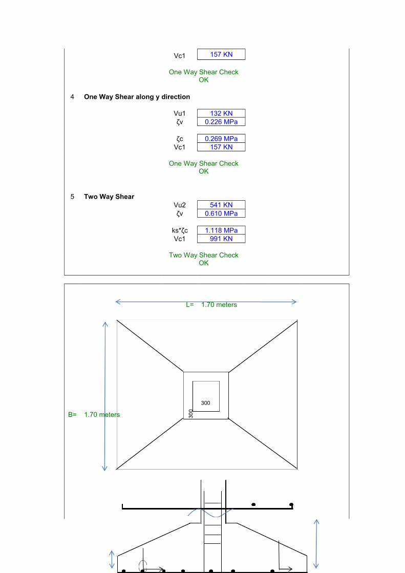
Vc1 157 KN
One Way Shear Check
OK 4 One Way Shear along y direction Vu1 132 KN ζv 0.226 MPa ζc 0.269 MPa Vc1 157 KN
One Way Shear Check
OK 5 Two Way Shear Vu2 541 KN ζv 0.610 MPa ks*ζc 1.118 MPa Vc1 991 KN
Two Way Shear Check
OK
L= 1.70 meters
300
B= 1.70 meters 300

400
mm
150 mm
12 mm
dia@ 150 mm c/c
12 mm dia
@ 150 mm c/c
DESIGN OF COMBINE FOOTING
GRID DESIGN CALCULATION:LOAD ON COLUMN C1 W1 = 247.018 KN FCK 20 MPALOAD ON COLUMN C2 W2 = 95.366 KNSELF WT. OF FOOTING 34.2384 KNTOTAL DESIGN LOAD ON FOOTING(P)= 376.6224 KNS.B.C OF SOIL = 150 KN/M2REQ.AREA OF FOOTING = P/S.B.C 2.510816 M2FOOTING SIZE PROV. L = 2 M B = 1.5 MAREA OF FOOTING PROVIDED = 3 M2
AREA PROV > AREA REQ.CENTER TO CENTER DIST. BET.COLUMN(b) = 1.676 MGEOMETRIC CENTER ,G.C =b/2 0.838 M(X)DIST. OF C.G OF COLM.FROM CENTER OF FOOTING(X)=W2Xb/(W1+W2)=
0.466825 MPROJ.a1 FROM CENTER OF COLUMN (C2)=a1 =(L/2-X) = 0.533175 MPROJ.a2 FROM CENTER OF COLUMN (C1)=a2=(L-a1-b) = -0.20917 MNET UPWARD PRESSURE(QNET)=(W1+W2)/(A PROV)=
114.128 KN/M2MINI.ECCEN.Emin =.02M 0.02 MMOMENT DUE TO Emini = 6.84768 KN-MAVAILABLE ECCEN, =(b/2-x)= 0.37117 MMOMENT DUE TO AVAILABLE ECCE.= 139.79281 KN-MCONSIDERING FULL WIDTH OF FOOTINGBM CALCULATION:QNET = 114.128 KN/M2MAX PRESSURE =QNET+6XM/BXLXL 120.97568 KN/MMINI PRESSURE = QNET-6XM/BXLXL 107.28032 KN/MSTRIP PRESSURE(q)=QNETXB = 171.192 KN/MSHEAR FORCE V1=qxa1= 91.275292 KN
V2 =W1-V1 155.74271 KN

V3 =qxa2 = -35.80908 KNV4=W2-V2= -60.37671 KN
POSITION OF ZERO SHEAR (Y)=(W1-q*a1)/qY = 0.90975 M
BENDING MOMENT CALCULATION:M1 = q*a1*a1/2 KN-M 24.3329 KNMM2 = q*a2*a2/2 KN-M 3.74518 KN-MM3 = q*(y+a1)2/2-w1*y KN-M -46.51097 KN-M
MAX. SAGGING BEND.MOM 24.332851 KN-MIS 456 1978 APPENDIX E CLAUSE 37.1EFF.DEPTH FROM MAX BENDING MOMENT CONSIDARATION:d=sqrt(mu*1000000/(.138*fck*B))= 76.664857
PROVIDE D = 200 MMd =D-50-10 140
K= MU/B*d = 0.827648Pt FROM TABLE 2 SP 16 IS 456 1978Pt minimum according to IS 456 1978Pt = 0.15 %AST=Pt*B*d/100 315 MM2 AST RQEUSE 10 MM BARS 78.5 MM2
PROVIDE AT 150 C/C MM
AST PROVD. 785 MM2> AST REQ OKCHECK FOR SHEAR (ONE WAY SHEAR)AT d FROM FACE OF COLUMN NO 1VU= QNET*(a1-d)= 44.8723 KNSHEAR STRESS=VU/Bd= 0.21368 MPAVd<1.5Vc hence okCHECK FOR SHEAR (TWO WAY SHEAR)AT d/2 FROM FACE OF COLUMN NO 1SIZE OF COLUMNSC1 300 300 MMC2 450 230 MMb+d 440 MMh+d 440 MMCIRCUMFERENCE © =(b+d+h+d)*2
1760 MMPUNCHING FORCE = W1-QNET*((b+d)*(h+d))
224.922819 KNSHEAR STRESS= 287.28/C*d
0.91283612P.STRESS AT d/2 < 3Vc OKEFF.DEPTH FROM PUNCHING SHEARd=(w1*1000)/(b+D+h+D) 192.983 MM
d prov > dreqhence ok