structural tanks and components
DESCRIPTION
A description of tanks and vessels, for softeners and filtersTRANSCRIPT

Color Options: AL - Almond BL - Blue BK - Black GR - Gray NA - Natural
The ideal pressurevessel for residentialand light commercialwater softener /filtration applications.
Structural Poly Glass™ pressure
vessels provide years of reliable
service for water softener and
water filtration applications.
These slim-diameter tanks hold
up to 49 gallons of water and offer
unmatched strength and chemical
resistance. All 6"-13" Poly Glass
vessels are backed by an exclusive
10-year warranty. All 14"-16"
Poly Glass vessels are backed by an
exclusive 5-year warranty.
Material of construction
Inner shell material:Polyethylene
Available inlets:See chart
Operating parameters
Maximum operating pressure: 150 psi
Maximum operating temperature:120° F
Design parameters – Pentair
Safety factor:4:1 (Minimum burst at 600 psi)
Cycle test:250,000 cycles without leakage
Design parameters – NSF
Safety factor:4:1 (Minimum burst at 600 psi)
Cycle test:100,000 cycles without leakage
Size System Height w/ Base Height w/o Base Capacity Cubic MinimumPart No. (Inches) Connection Inches / mm Inches / mm Gallons / Liters Feet Colors Order Quantity
30109 06 x 13 2.5" Threaded 13.2 / 335 12.6 / 320 1.1 / 4.2 0.15 AL, BL, NA See Factory
30127 06 x 18 2.5" Threaded 18.6 / 472 18.0 / 457 1.8 / 6.8 0.24 All None
30151 06 x 35 2.5" Threaded 35.8 / 909 35.2 / 894 3.8 / 14.4 0.51 All None
30190 07 x 35 2.5" Threaded 35.6 / 904 35.3 / 897 5.2 / 19.7 0.7 AL, BL, NA See Factory
30213 07 x 44 2.5" Threaded 43.7 / 1110 43.4 / 1102 6.7 / 25.4 0.9 AL, BL, NA See Factory
31835 08 x 18 2.5" Threaded 18.8 / 478 18.5 / 470 3.28 / 12.0 - AL, NA See Factory
30264 08 x 35 2.5" Threaded 35.6 / 904 35.3 / 897 6.6 / 25.0 0.88 All None
30286 08 x 40 2.5" Threaded 40.2 / 1021 39.9 / 1013 7.8 / 29.5 1.04 All None
30305 08 x 44 2.5" Threaded 44.4 / 1128 44.1 / 1120 8.7 / 32.9 1.16 All None
30317 09 x 18 2.5" Threaded 18.6 / 472 18.0 / 457 3.9 / 14.8 0.52 AL, BL, NA See Factory
30347 09 x 35 2.5" Threaded 35.6 / 904 35.3 / 897 8.3 / 31.4 1.11 All None
30360 09 x 40 2.5" Threaded 40.2 / 1021 39.9 / 1013 9.5 / 31.4 1.27 All None
30383 09 x 48 2.5" Threaded 48.2 / 1224 47.9 / 1217 11.8 / 44.7 1.58 All None
30460 10 x 35 2.5" Threaded 35.6 / 904 35.3 / 897 10.2 / 38.6 1.36 All None
30491 10 x 40 2.5" Threaded 40.3 / 1024 40.1 / 1018 11.5 / 43.5 1.54 All None
30523 10 x 44 2.5" Threaded 44.6 / 1133 44.4 / 1128 13.1 / 49.6 1.75 All None
30546 10 x 47 2.5" Threaded 47.4 / 1204 46.9 / 1191 15.1 / 57.0 2.02 All None
30579 10 x 54 2.5" Threaded 54.8 / 1392 54.6 / 1387 16.4 / 62.0 2.19 All None
32065 10 x 54 2.5" Threaded 1.25 TDH 54.8 / 1392 54.6 / 1387 16.4 / 62.0 2.19 All None
30615 12 x 42 2.5" Threaded 42.8 / 1087 42.2 / 1072 19.1 / 72.0 2.55 AL, NA See Factory
30617 12 x 42 4.5" Threaded (BTRS) 42.8 / 1087 42.2 / 1072 19.1 / 72.0 2.55 AL, NA See Factory
30646 12 x 48 2.5" Threaded 48.8 / 1240 48.4 / 1229 20.6 / 78.0 2.75 All None
30666 12 x 52 2.5" Threaded 52.9 / 1344 52.4 / 1331 22.2 / 84.0 2.97 All None
30669 12 x 52 4.0" Threaded 52.9 / 1344 52.4 / 1331 22.2 / 84.0 2.97 AL, BL, NA See Factory
32127 12 x 52 4.5" Threaded (BTRS) 52.9 / 1344 52.4 / 1331 22.2 / 84.0 2.97 AL, NA See Factory
30721 13 x 54 2.5" Threaded 54.6 / 1387 53.9 / 1369 27.5 / 104.0 3.68 All None
30724 13 x 54 4.0" Threaded 54.6 / 1387 53.9 / 1369 27.5 / 104.0 3.68 AL, BL, NA See Factory
31389 14 x 47 2.5" Threaded 46.5 / 1181 46.0 / 1168 27.5 / 104.0 3.68 AL, NA See Factory
30745 14 x 47 4.0" Threaded 46.5 / 1181 46.0 / 1168 27.5 / 104.0 3.68 AL, NA See Factory
32006 14 x 47 4.5" Threaded (BTRS) 46.5 / 1181 46.0 / 1168 27.5 / 104.0 3.68 AL, NA See Factory
30783 14 x 65 2.5" Threaded 64.6 / 1641 64.3 / 1633 40.6 / 154.0 5.43 AL, BL, NA See Factory
30785 14 x 65 4.0" Threaded 64.6 / 1641 64.3 / 1633 40.6 / 154.0 5.43 All None
31627 16 x 65 2.5" Threaded 64.6 / 1641 64.3 / 1633 49.0 / 185.0 6.55 AL, BL, NA See Factory
30912 16 x 65 4.0" Threaded 64.6 / 1641 64.3 / 1633 49.0 / 185.0 6.55 All None
Poly Glass™ Vessels Poly Glass
Specifications
[ 4 ] [ 5 ]
6˝-13˝ – 10 years from date of manufacture
14˝-16˝ – 5 years from date of manufacture
All Poly Glass tanks are warranted to be free fromdefects in materials and workmanship for a periodof 5/10 years from the date of manufacture (seeabove) if the vessel is operated within the pre-scribed pressure and temperature ratings stated onthe tank label.
Not covered by this warranty is damage resultingfrom freezing, external impact, chemical attackfrom liquid and gasses, exposure to vacuum, natu-ral disasters, or other applications of the productbeyond residential water softeners and filters.

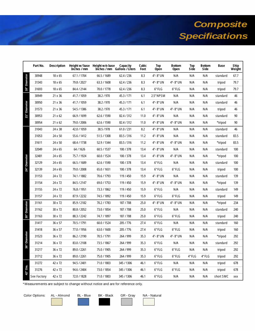
Composite Vessels Composite
Specifications
Part No. Description Height w/ base Height w/o base Capacity Cubic Top Bottom Top Bottom Base ShipInches / mm Inches / mm Gallons / Liters Feet Open Open Side Side Weight
30948 18 x 65 67.1 / 1704 66.5 / 1689 62.4 / 236 8.3 4"- 8" UN N/A N/A N/A standard 67.7
31343 18 x 65 79.8 / 2027 63.3 / 1608 62.4 / 236 8.3 4"- 8" UN 4"- 8" UN N/A N/A tripod 79.7
31693 18 x 65 84.4 / 2144 70.0 / 1778 62.4 / 236 8.3 6" FLG 6" FLG N/A N/A tripod 79.7
30949 21 x 36 41.7 / 1059 38.2 / 970 45.3 / 171 6.1 2.5" NPSM N/A N/A N/A standard 46
30950 21 x 36 41.7 / 1059 38.2 / 970 45.3 / 171 6.1 4"- 8" UN N/A N/A N/A standard 46
31573 21 x 36 54.5 / 1386 38.2 / 970 45.3 / 171 6.1 4"- 8" UN 4"- 8" UN N/A N/A tripod 46
30953 21 x 62 66.9 / 1699 62.6 / 1590 82.4 / 312 11.0 4"- 8" UN N/A N/A N/A standard 90
30954 21 x 62 79.0 / 2006 62.6 / 1590 82.4 / 312 11.0 4"- 8" UN 4"- 8" UN N/A N/A *tripod 90
31043 24 x 38 42.0 / 1059 38.5 / 978 61.0 / 231 8.2 4"- 8" UN N/A N/A N/A standard 46
31053 24 x 50 55.6 / 1412 51.5 / 1308 83.5 / 316 11.2 4"- 8" UN N/A N/A N/A standard 83.5
31611 24 x 50 68.4 / 1738 52.9 / 1344 83.5 / 316 11.2 4"- 8" UN 4"- 8" UN N/A N/A *tripod 83.5
32049 24 x 65 64 / 1626 60.5 / 1537 100 / 378 13.4 4"- 8" UN N/A N/A N/A standard 100
32481 24 x 65 75.7 / 1924 60.0 / 1524 100 / 378 13.4 4"- 8" UN 4"- 8" UN N/A N/A *tripod 100
32129 24 x 65 66.5 / 1689 62.6 / 1590 100 / 378 13.4 6" FLG N/A N/A N/A standard 100
32139 24 x 65 79.0 / 2008 65.0 / 1651 100 / 378 13.4 6" FLG 6" FLG N/A N/A tripod 100
31153 24 x 72 74.1 / 1882 70.6 / 1793 119 / 450 15.9 4"- 8" UN N/A N/A N/A standard 139
31154 24 x 72 84.5 / 2147 69.0 / 1753 119 / 450 15.9 4"- 8" UN 4"- 8" UN N/A N/A *tripod 139
31155 24 x 72 76.8 / 1951 73.3 / 1862 119 / 450 15.9 6" FLG N/A N/A N/A standard 149
31157 24 x 72 87.9 / 2232 74.5 / 1892 119 / 450 15.9 6" FLG 6" FLG N/A N/A tripod 149
31161 30 x 72 85.9 / 2182 70.2 / 1783 187 / 708 25.0 4"- 8" UN 4"- 8" UN N/A N/A *tripod 234
31162 30 x 72 80.8 / 2052 73.0 / 1854 187 / 708 25.0 6" FLG N/A N/A N/A standard 240
31163 30 x 72 88.3 / 2242 74.7 / 1897 187 / 708 25.0 6" FLG 6" FLG N/A N/A tripod 240
31417 36 x 57 70.5 / 1791 60.0 / 1524 205 / 776 27.4 6" FLG N/A N/A N/A standard 160
31418 36 x 57 77.0 / 1956 63.0 / 1600 205 / 776 27.4 6" FLG 6" FLG N/A N/A tripod 160
31523 36 x 72 86.2 / 2190 70.5 / 1791 264 / 999 35.3 4"- 8" UN 4"- 8" UN N/A N/A *tripod 292
31214 36 x 72 83.0 / 2108 73.5 / 1867 264 / 999 35.3 6" FLG N/A N/A N/A standard 292
31217 36 x 72 89.0 / 2261 75.0 / 1905 264 / 999 35.3 6" FLG 6" FLG N/A N/A tripod 292
31712 36 x 72 89.0 / 2261 75.0 / 1905 264 / 999 35.3 6" FLG 6" FLG 4" FLG 4" FLG tripod 292
31272 42 x 72 94.5 / 2401 71.0 / 1803 345 / 1306 46.1 6" FLG N/A N/A N/A tripod 678
31276 42 x 72 94.6 / 2404 73.0 / 1854 345 / 1306 46.1 6" FLG 6" FLG N/A N/A tripod 678
See Factory 42 x 72 72.0 / 1828 71.0 / 1803 345 / 1306 46.1 6" FLG N/A N/A N/A short SMC xxx
Material of construction
Inner shell material:Polyethylene
Operating parameters
Maximum operating pressure: 150 psi
Maximum operating temperature: 150° F
Design parameters – Pentair
Safety factor:4:1 (Minimum burst at 600 psi)
Cycle test:250,000 cycles without leakage
Design parameters – NSF
Safety factor:4:1 (Minimum burst at 600 psi)
Cycle test:100,000 cycles without leakage
Design parameters – ASME
Safety factor:5:1 Top/bottom flange (Minimum burst at 750 psi)6:1 Side flange (Minimum burst at 900 psi)
Cycle test:33,000 cycles without leakage (Top/bottom flange)100,000 cycles without leakage (Side flange)
The non-corrosive, cost-effective solutionfor commercial / industrial water treatment and storage.
Structural Composite pressure
vessels offer composite fiberglass
construction for outstanding
performance and durability in
harsh chemical environments.
With capacities up to 1600 gallons
and a variety of options, we can
tailor a vessel to meet your needs.
All Structural Composite vessels
are warranted for 5 years.
Color Options: AL - Almond BL - Blue BK - Black GR - Gray NA - Natural
36"
Dia
mete
r30"
Dia
mete
r24"
Dia
mete
r21"
Dia
mete
r18"
Dia
mete
r42"
Dia
.
All Composite tanks are warranted to be free fromdefects in materials and workmanship for a periodof 5 years from the date of manufacture if the ves-sel is operated within the prescribed pressure andtemperature ratings stated on the tank label.
Not covered by this warranty is damage resultingfrom freezing, external impact, chemical attackfrom liquid and gasses, exposure to vacuum, natu-ral disasters, or other applications of the productbeyond residential water softeners and filters.
*Measurements are subject to change without notice and are for reference only.

Composite
SpecificationsComposite Vessels
Part No. Description Height w/ base Height w/o base Capacity Cubic Top Bottom Top Bottom Base ShipInches / mm Inches / mm Gallons / Liters Feet Open Open Side Side Weight
31281 48 x 72 91.8 / 2332 76.0 / 1930 463 / 1753 61.9 6" FLG N/A N/A N/A tripod 780
31285 48 x 72 92.8 / 2357 77.0 / 1955 463 / 1753 61.9 6" FLG 6" FLG N/A N/A tripod 780
31647 48 x 72 93.8 / 2383 78.0 / 1981 463 / 1753 61.9 16" MWY 6" FLG N/A N/A tripod 780
31283 48 x 72 96.6 / 2454 80.8 / 2052 463 / 1753 61.9 6" FLG 6" FLG 4" FLG 4" FLG tripod 780
31432 48 x 72 97.5 / 2477 81.7 / 2075 463 / 1753 61.9 16" MWY 6" FLG 4" FLG 4" FLG tripod 780
31390 63 x 67 79.5 / 2324 67.0 / 1702 600 / 2271 80.2 6" FLG 6" FLG N/A N/A tripod 900
Call Factory 63 x 67 79.5 / 2324 67.0 / 1702 600 / 2271 80.2 10" FLG 6" FLG N/A N/A tripod *
31290 63 x 67 80.3 / 2344 67.8 / 1722 600 / 2271 80.2 16" MWY 6" FLG N/A N/A tripod 900
32008 63 x 67 80.3 / 2344 67.8 / 1722 600 / 2271 80.2 16" MWY 10" FLG N/A N/A tripod 900
31326 63 x 86 96.6 / 2758 84.1 / 2136 850 / 3218 114 6" FLG 6" FLG N/A N/A tripod 1425
32678 63 x 86 96.6 / 2758 84.1 / 2136 850 / 3218 114 6" FLG 6" FLG 4" FLG 4" FLG tripod 1425
32253 63 x 86 96.6 / 2758 84.1 / 2136 850 / 3218 114 10" FLG 6" FLG N/A N/A tripod 1200
31327 63 x 86 97.0 / 2769 84.5 / 2146 850 / 3218 114 16" MWY 6" FLG N/A N/A tripod 1200
31292 63 x 86 97.0 / 2769 84.5 / 2146 850 / 3218 114 16" MWY 6" FLG 4" FLG 4" FLG tripod 1425
32356 63 x 86 97.0 / 2769 84.5 / 2146 850 / 3218 114 16" MWY 10" FLG N/A N/A tripod 1425
32500 63 x 116 128.5 / 3264 116.0 / 2946 1250 / 4732 167 16" MWY 6" FLG N/A N/A tripod 1425
31325 63 x 116 128.5 / 3264 116.0 / 2946 1250 / 4732 167 16" MWY 6" FLG 4" FLG 4" FLG tripod 1775
Call Factory 63 x 116 128.5 / 3264 116.0 / 2946 1250 / 4732 167 16" MWY 10" FLG N/A N/A tripod *
31456 63 x 144 158.5 / 4026 146.0 / 3708 1600 / 6057 214 16" MWY 6" FLG N/A N/A tripod 2025
31607 63 x 144 158.5 / 4026 146.0 / 3708 1600 / 6057 214 16" MWY 6" FLG 4" FLG 4" FLG tripod 2025
31664 63 x 144 158.5 / 4026 146.0 / 3708 1600 / 6057 214 16" MWY 10" FLG N/A N/A tripod 2025
*Measurements are subject to change without notice and are for reference only.
Color Options: AL - Almond BL - Blue BK - Black GR - Gray NA - Natural
63"
Dia
mete
r48"
Dia
mete
r
NOTE: See flex connection and vacuum breaker information on page 13.
X
Tank Dia. Adder Ht. (X)Fleck Valve Inches / mm Inches / mm
2750 18 / 457 6.5 / 165
2850 21 / 533 6.5 / 165
2900 24, 30 / 610, 762 12 / 305
2930 36 / 914 13 / 330
3150 42 / 1067 10 / 254
3900 48-63 / 1219-1600 15 /381
Installation Tips:
• Bolt base to floor• Calculate height for valve and
base combined (see photo)
Nominal Diameter
D Gallons* Gallon / Inch A(inches) (One Dome) (Approx.) (Sq. Feet)
12 1.0 0.5 0.7
13 1.4 0.5 0.9
14 1.7 0.6 1.1
16 2.7 0.8 1.3
18 3.7 1.0 1.8
21 6.2 1.4 2.4
24 9.3 1.9 3.0
30 18 2.9 4.6
36 33 4.2 6.7
42 52 5.7 9.0
48 74 7.5 12.0
63 168 13.0 20.0
Dome Volume (gallons)and Straight Wall Gallon per Inch
*Cubic Ft. = 0.1337 x Gallons
Vacuum Breaker Installation Flex Connectors Installation
TANK
BASE
SHUTOFF
VALVE
VACUUM BREAKERCONTROL VALVE VACUUM BREAKER
(LOCATION OPTIONAL)
CONTROLVALVE
FLEXCONNECTORS
VACUUM BREAKER
FLEX CONNECTORSCONTROLVALVE
A
A A
D
D
GAL / IN
*Cubic Ft. = 0.1337 x Gallons
A
NOTE: Flexible connectors must be installed between hard piping and tank openings. These pressure vessels are rated for aninternal negative pressure of 5˝ HG (17 Pa) vacuum below atmospheric. If negative pressure could ever exceed 5˝ Hg (17 Pa), anadequate vacuum breaker must also be properly installed. Failure to install flex connection properly, or improper installation of avacuum breaker when required, may void the warranty.

Chemical
ResistanceComposite Vessels
SIZE
# FULL THREADS
45°
B.C.
I.D.
A O.D.
L
VINYLESTERCOVERSTANDARD 1–1/4" NPT
THREADVENTSTANDARD
2"
VENTPLUGSTANDARD
EDPM SEAL ANDSTAINLESSSTEEL BOLT KITSTANDARD
L I.D. B.C.
O.D.
B
Top and Bottom Opening Threads
Composite/ Number of FullSize Polyglass Threads Composite
2.5"- 8" NPSM 6 3 min 6
4"- 8" UN 7 3 min 7
4.5"- 8" Buttress 7 3 min 7
Top and Bottom Opening Flanges/Manway
A Number WeightSize L I.D. B.C. O.D. Bolt Dia. of Holes (lbs.)
6" SNA 3.6" 5.9" 8.5" 9.4" 0.31" 12 5.8
10" ANSI 3.7" 10.0" 14.3" 16.0" 0.88" 12 17.8
16" Manway SNA 4.3" 16.0" 20.4" 21.3" 0.50" 24 34.0
Manway Cover
Pressure Material Rating Tapping
CPVC 100 psi As requested
VE 150 psi As shown only
B Number WeightSize L I.D. B.C. O.D. Bolt Dia. of Holes (lbs.)
4" ANSI 4.1" 4.0" 7.5" 9.0" 0.63" 8 6.4
Side Flange
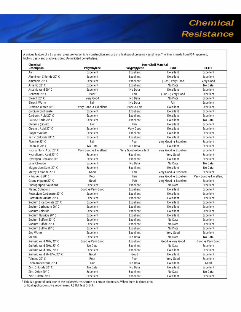
A unique feature of a Structural pressure vessel is its construction and use of a leak-proof pressure vessel liner. The liner is made from FDA-approved, highly stress- and crack-resistant, UV-inhibited polyethylene.
Chemical Inner Shell Material Description Polyethylene Polypropylene PVDF ECTFEAir Excellent Excellent Excellent ExcellentAluminum Chloride 20° C Excellent Excellent Excellent ExcellentAmmonia 20° C Excellent Excellent ( Gas ) Very Good Very GoodArsenic 20° C Excellent Excellent No Data No DataArsenic Acid 20° C Excellent No Data Excellent ExcellentBenzene 20° C Poor Fair ( 38° C ) Very Good ExcellentBleach 20° C Very Good No Data No Data ExcellentBleach Warm Fair No Data Fair ExcellentBromine Water 20° C Very Good ➔ Excellent Poor ➔ Fair Excellent ExcellentCalcium Carbonate Excellent Excellent Excellent ExcellentCarbonic Acid 20° C Excellent Excellent Excellent ExcellentCaustic Soda 20° C Excellent Excellent Excellent No DataChlorine (Liquid) Fair Fair Excellent ExcellentChromic Acid 20° C Excellent Very Good Excellent ExcellentCopper Sulfate Excellent Excellent Excellent ExcellentFerric Chloride 20° C Excellent Excellent Excellent ExcellentFluorine 20° C Fair Poor Very Good ➔ Excellent ExcellentFreon 11 20° C No Data No Data Excellent ExcellentHydrochloric Acid 20° C Very Good ➔ Excellent Very Good ➔ Excellent Very Good ➔ Excellent ExcellentHydrofluoric Acid 20° C Excellent Excellent Very Good ExcellentHydrogen Peroxide 20° C Excellent Excellent Excellent ExcellentLime Chloride Excellent No Data No Data No DataMagnesium Salts 20° C Excellent Excellent Excellent No DataMethyl Chloride 20° C Good Fair Very Good ➔ Excellent ExcellentNitric Acid 20° C Poor Fair Very Good ➔ Excellent Very Good ➔ ExcellentOzone (4 ppm) 20° C Good Fair Very Good ➔ Excellent ExcellentPhotographic Solutions Excellent Excellent No Data ExcellentPlating Solutions Good ➔ Very Good Excellent Excellent ExcellentPotassium Carbonate 20° C Excellent Excellent Excellent ExcellentPotassium Sulfate 20° C Excellent Excellent Excellent ExcellentSodium Bicarbonate 20° C Excellent Excellent Excellent ExcellentSodium Carbonate 20° C Excellent Excellent Excellent ExcellentSodium Chloride Excellent Excellent Excellent ExcellentSodium Fluoride 20° C Excellent Excellent Excellent ExcellentSodium Sulfate 20° C Excellent Excellent No Data ExcellentSodium Sulfide 20° C Excellent Excellent No Data ExcellentSodium Sulfite 20° C Excellent Excellent No Data ExcellentSea Water Excellent Excellent Very Good ExcellentSteam Excellent No Data No Data No DataSulfuric Acid 10%, 20° C Good ➔ Very Good Excellent Good ➔ Very Good Good ➔ Very GoodSulfuric Acid 20%, 20° C No Data Excellent No Data ExcellentSulfuric Acid 50%, 20° C Excellent Excellent Excellent ExcellentSulfuric Acid 76-97%, 20° C Good Good Excellent ExcellentToluene 20° C Poor Poor Very Good ExcellentTrichlorobenzene 20° C Fair No Data Excellent GoodZinc Chloride 20° C No Data No Data Excellent ExcellentZinc Oxide 20° C Excellent Excellent No Data No DataZinc Sulfate 20° C Excellent Excellent Excellent Excellent
* This is a general indicator of the polymer’s resistance to certain chemicals. When there is doubt or incritical applications, we recommend ASTM Test D-543.
Chemical
ResistanceComposite Vessels
SIZE
# FULL THREADS
45°
B.C.
I.D.
A O.D.
L
VINYLESTERCOVERSTANDARD 1–1/4" NPT
THREADVENTSTANDARD
2"
VENTPLUGSTANDARD
EDPM SEAL ANDSTAINLESSSTEEL BOLT KITSTANDARD
L I.D. B.C.
O.D.
B
Top and Bottom Opening Threads
Composite/ Number of FullSize Polyglass Threads Composite
2.5"- 8" NPSM 6 3 min 6
4"- 8" UN 7 3 min 7
4.5"- 8" Buttress 7 3 min 7
Top and Bottom Opening Flanges/Manway
A Number WeightSize L I.D. B.C. O.D. Bolt Dia. of Holes (lbs.)
6" SNA 3.6" 5.9" 8.5" 9.4" 0.31" 12 5.8
10" ANSI 3.7" 10.0" 14.3" 16.0" 0.88" 12 17.8
16" Manway SNA 4.3" 16.0" 20.4" 21.3" 0.50" 24 34.0
Manway Cover
Pressure Material Rating Tapping
CPVC 100 psi As requested
VE 150 psi As shown only
B Number WeightSize L I.D. B.C. O.D. Bolt Dia. of Holes (lbs.)
4" ANSI 4.1" 4.0" 7.5" 9.0" 0.63" 8 6.4
Side Flange
A unique feature of a Structural pressure vessel is its construction and use of a leak-proof pressure vessel liner. The liner is made from FDA-approved, highly stress- and crack-resistant, UV-inhibited polyethylene.
Chemical Inner Shell Material Description Polyethylene Polypropylene PVDF ECTFEAir Excellent Excellent Excellent ExcellentAluminum Chloride 20° C Excellent Excellent Excellent ExcellentAmmonia 20° C Excellent Excellent ( Gas ) Very Good Very GoodArsenic 20° C Excellent Excellent No Data No DataArsenic Acid 20° C Excellent No Data Excellent ExcellentBenzene 20° C Poor Fair ( 38° C ) Very Good ExcellentBleach 20° C Very Good No Data No Data ExcellentBleach Warm Fair No Data Fair ExcellentBromine Water 20° C Very Good ➔ Excellent Poor ➔ Fair Excellent ExcellentCalcium Carbonate Excellent Excellent Excellent ExcellentCarbonic Acid 20° C Excellent Excellent Excellent ExcellentCaustic Soda 20° C Excellent Excellent Excellent No DataChlorine (Liquid) Fair Fair Excellent ExcellentChromic Acid 20° C Excellent Very Good Excellent ExcellentCopper Sulfate Excellent Excellent Excellent ExcellentFerric Chloride 20° C Excellent Excellent Excellent ExcellentFluorine 20° C Fair Poor Very Good ➔ Excellent ExcellentFreon 11 20° C No Data No Data Excellent ExcellentHydrochloric Acid 20° C Very Good ➔ Excellent Very Good ➔ Excellent Very Good ➔ Excellent ExcellentHydrofluoric Acid 20° C Excellent Excellent Very Good ExcellentHydrogen Peroxide 20° C Excellent Excellent Excellent ExcellentLime Chloride Excellent No Data No Data No DataMagnesium Salts 20° C Excellent Excellent Excellent No DataMethyl Chloride 20° C Good Fair Very Good ➔ Excellent ExcellentNitric Acid 20° C Poor Fair Very Good ➔ Excellent Very Good ➔ ExcellentOzone (4 ppm) 20° C Good Fair Very Good ➔ Excellent ExcellentPhotographic Solutions Excellent Excellent No Data ExcellentPlating Solutions Good ➔ Very Good Excellent Excellent ExcellentPotassium Carbonate 20° C Excellent Excellent Excellent ExcellentPotassium Sulfate 20° C Excellent Excellent Excellent ExcellentSodium Bicarbonate 20° C Excellent Excellent Excellent ExcellentSodium Carbonate 20° C Excellent Excellent Excellent ExcellentSodium Chloride Excellent Excellent Excellent ExcellentSodium Fluoride 20° C Excellent Excellent Excellent ExcellentSodium Sulfate 20° C Excellent Excellent No Data ExcellentSodium Sulfide 20° C Excellent Excellent No Data ExcellentSodium Sulfite 20° C Excellent Excellent No Data ExcellentSea Water Excellent Excellent Very Good ExcellentSteam Excellent No Data No Data No DataSulfuric Acid 10%, 20° C Good ➔ Very Good Excellent Good ➔ Very Good Good ➔ Very GoodSulfuric Acid 20%, 20° C No Data Excellent No Data ExcellentSulfuric Acid 50%, 20° C Excellent Excellent Excellent ExcellentSulfuric Acid 76-97%, 20° C Good Good Excellent ExcellentToluene 20° C Poor Poor Very Good ExcellentTrichlorobenzene 20° C Fair No Data Excellent GoodZinc Chloride 20° C No Data No Data Excellent ExcellentZinc Oxide 20° C Excellent Excellent No Data No DataZinc Sulfate 20° C Excellent Excellent Excellent Excellent
* This is a general indicator of the polymer’s resistance to certain chemicals. When there is doubt or incritical applications, we recommend ASTM Test D-543.

Pressure Vessel Requirement Form
and Engineering Guide Specifications
A2
A4
A3
A1
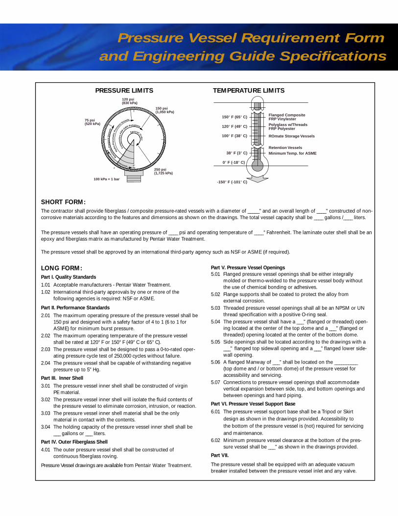
LONG FORM:Part I. Quality Standards
1.01 Acceptable manufacturers - Pentair Water Treatment.1.02 International third-party approvals by one or more of the
following agencies is required: NSF or ASME.
Part II. Performance Standards
2.01 The maximum operating pressure of the pressure vessel shall be150 psi and designed with a safety factor of 4 to 1 (6 to 1 forASME) for minimum burst pressure.
2.02 The maximum operating temperature of the pressure vesselshall be rated at 120° F or 150° F (49° C or 65° C).
2.03 The pressure vessel shall be designed to pass a 0-to-rated oper-ating pressure cycle test of 250,000 cycles without failure.
2.04 The pressure vessel shall be capable of withstanding negativepressure up to 5" Hg.
Part III. Inner Shell
3.01 The pressure vessel inner shell shall be constructed of virgin PE material.
3.02 The pressure vessel inner shell will isolate the fluid contents ofthe pressure vessel to eliminate corrosion, intrusion, or reaction.
3.03 The pressure vessel inner shell material shall be the only material in contact with the contents.
3.04 The holding capacity of the pressure vessel inner shell shall be___ gallons or ___ liters.
Part IV. Outer Fiberglass Shell
4.01 The outer pressure vessel shell shall be constructed of continuous fiberglass roving.
Pressure Vessel drawings are available from Pentair Water Treatment.
Part V. Pressure Vessel Openings
5.01 Flanged pressure vessel openings shall be either integrally molded or thermo-welded to the pressure vessel body withoutthe use of chemical bonding or adhesives.
5.02 Flange supports shall be coated to protect the alloy from external corrosion.
5.03 Threaded pressure vessel openings shall all be an NPSM or UNthread specification with a positive O-ring seal.
5.04 The pressure vessel shall have a ___" (flanged or threaded) open-ing located at the center of the top dome and a ___" (flanged orthreaded) opening located at the center of the bottom dome.
5.05 Side openings shall be located according to the drawings with a___" flanged top sidewall opening and a ___" flanged lower side-wall opening.
5.06 A flanged Manway of ___" shall be located on the __________ (top dome and / or bottom dome) of the pressure vessel foraccessibility and servicing.
5.07 Connections to pressure vessel openings shall accommodatevertical expansion between side, top, and bottom openings andbetween openings and hard piping.
Part VI. Pressure Vessel Support Base
6.01 The pressure vessel support base shall be a Tripod or Skirtdesign as shown in the drawings provided. Accessibility tothe bottom of the pressure vessel is (not) required for servicingand maintenance.
6.02 Minimum pressure vessel clearance at the bottom of the pres-sure vessel shall be ___" as shown in the drawings provided.
Part VII.
The pressure vessel shall be equipped with an adequate vacuumbreaker installed between the pressure vessel inlet and any valve.
TEMPERATURE LIMITS
SHORT FORM:The contractor shall provide fiberglass / composite pressure-rated vessels with a diameter of _____" and an overall length of ____" constructed of non-corrosive materials according to the features and dimensions as shown on the drawings. The total vessel capacity shall be ____ gallons /____ liters.
The pressure vessels shall have an operating pressure of ____ psi and operating temperature of ____° Fahrenheit. The laminate outer shell shall be anepoxy and fiberglass matrix as manufactured by Pentair Water Treatment.
The pressure vessel shall be approved by an international third-party agency such as NSF or ASME (if required).
250 psi(1,725 kPa)
150 psi(1,050 kPa)
75 psi(520 kPa)
100 kPa = 1 bar
120 psi(830 kPa)
0
Pressure Vacuum
Reten
tion
Pre
ssu
reV
esse
ls
Hyd
ro-P
neu
mat
icP
ress
ureVessels
Com
po
site
s-FR
P-GRP-Polyglass
Special Ord
er
-5"Hg
PRESSURE LIMITS
-150° F (-101° C)
0° F (-18° C)
38° F (3° C)
120° F (49° C)
150° F (65° C)
Minimum Temp. for ASME
Polyglass w/ThreadsFRP Polyester
ROmate Storage Vessels
Retention Vessels
Flanged CompositeFRP Vinylester
100° F (38° C)
Composite Vessels
Instructions: Circle or fill in appropriate data. Fax sheet to Pentair Water Treatment (440-286-9673 or 1-800-942-7659) for a quote.
Units English or Metric Circle or fill in appropriate data
Pressure PSI or kPa min. max.
Temperature ° F or ° C min. max.
Liner Material PE
Volume Gallons or Liters
Height Constraint (H) Inches or mm
Width Constraint (W) Inches or mm
Pressure Vessel Inches12" 13" 14" 16" 18" 21"
Diameter 24" 30" 36" 42" 48" 63"
Pressure Vessel Inches or mm For standard lengths, refer to Specification pages.Length
Top Opening A1 2.5" 4"-8" 4.5"-8" 6" SNA 10" ANSI 16" SNANPSM UN Buttress Flange Flange Manway
Bottom Opening A2 2.5" 4"-8" 4.5"-8" 6" SNA 10" ANSI 16" SNANPSM UN Buttress Flange Flange Manway
Side Top Opening A3 36" 48" 63" Diameter Only 4"
Side Bottom Opening A4 36" 48" 63" Diameter Only 4"
Distributor - Top Diffuser High Flow
Distributor - Side Top Diffuser High Flow
Distributor - Side Btm. Hub & Lateral Fishbone High Flow
Distributor - Bottom Hub & Lateral Fishbone High Flow
Pressure Vessel Base None Standard Extended Tripod
Flange Covers VE CPVC Noryl Other :
O-Ring Material EPDM VITON Other :
Vessel ContentsPlease list.
Pressure Vessel Color Natural Almond Blue Black Gray
Vessel Quantity Number of Units :
ASME Code Yes No
Pressure Vessel Requirement Form
and Engineering Guide Specifications
A2
A4
A3
A1
LONG FORM:Part I. Quality Standards
1.01 Acceptable manufacturers - Pentair Water Treatment.1.02 International third-party approvals by one or more of the
following agencies is required: NSF or ASME.
Part II. Performance Standards
2.01 The maximum operating pressure of the pressure vessel shall be150 psi and designed with a safety factor of 4 to 1 (6 to 1 forASME) for minimum burst pressure.
2.02 The maximum operating temperature of the pressure vesselshall be rated at 120° F or 150° F (49° C or 65° C).
2.03 The pressure vessel shall be designed to pass a 0-to-rated oper-ating pressure cycle test of 250,000 cycles without failure.
2.04 The pressure vessel shall be capable of withstanding negativepressure up to 5" Hg.
Part III. Inner Shell
3.01 The pressure vessel inner shell shall be constructed of virgin PE material.
3.02 The pressure vessel inner shell will isolate the fluid contents ofthe pressure vessel to eliminate corrosion, intrusion, or reaction.
3.03 The pressure vessel inner shell material shall be the only material in contact with the contents.
3.04 The holding capacity of the pressure vessel inner shell shall be___ gallons or ___ liters.
Part IV. Outer Fiberglass Shell
4.01 The outer pressure vessel shell shall be constructed of continuous fiberglass roving.
Pressure Vessel drawings are available from Pentair Water Treatment.
Part V. Pressure Vessel Openings
5.01 Flanged pressure vessel openings shall be either integrally molded or thermo-welded to the pressure vessel body withoutthe use of chemical bonding or adhesives.
5.02 Flange supports shall be coated to protect the alloy from external corrosion.
5.03 Threaded pressure vessel openings shall all be an NPSM or UNthread specification with a positive O-ring seal.
5.04 The pressure vessel shall have a ___" (flanged or threaded) open-ing located at the center of the top dome and a ___" (flanged orthreaded) opening located at the center of the bottom dome.
5.05 Side openings shall be located according to the drawings with a___" flanged top sidewall opening and a ___" flanged lower side-wall opening.
5.06 A flanged Manway of ___" shall be located on the __________ (top dome and / or bottom dome) of the pressure vessel foraccessibility and servicing.
5.07 Connections to pressure vessel openings shall accommodatevertical expansion between side, top, and bottom openings andbetween openings and hard piping.
Part VI. Pressure Vessel Support Base
6.01 The pressure vessel support base shall be a Tripod or Skirtdesign as shown in the drawings provided. Accessibility tothe bottom of the pressure vessel is (not) required for servicingand maintenance.
6.02 Minimum pressure vessel clearance at the bottom of the pres-sure vessel shall be ___" as shown in the drawings provided.
Part VII.
The pressure vessel shall be equipped with an adequate vacuumbreaker installed between the pressure vessel inlet and any valve.
TEMPERATURE LIMITS
SHORT FORM:The contractor shall provide fiberglass / composite pressure-rated vessels with a diameter of _____" and an overall length of ____" constructed of non-corrosive materials according to the features and dimensions as shown on the drawings. The total vessel capacity shall be ____ gallons /____ liters.
The pressure vessels shall have an operating pressure of ____ psi and operating temperature of ____° Fahrenheit. The laminate outer shell shall be anepoxy and fiberglass matrix as manufactured by Pentair Water Treatment.
The pressure vessel shall be approved by an international third-party agency such as NSF or ASME (if required).
250 psi(1,725 kPa)
150 psi(1,050 kPa)
75 psi(520 kPa)
100 kPa = 1 bar
120 psi(830 kPa)
0
Pressure Vacuum
Reten
tion
Pre
ssu
reV
esse
ls
Hyd
ro-P
neu
mat
icP
ress
ureVessels
Com
po
site
s-FR
P-GRP-Polyglass
Special Ord
er
-5"Hg
PRESSURE LIMITS
-150° F (-101° C)
0° F (-18° C)
38° F (3° C)
120° F (49° C)
150° F (65° C)
Minimum Temp. for ASME
Polyglass w/ThreadsFRP Polyester
ROmate Storage Vessels
Retention Vessels
Flanged CompositeFRP Vinylester
100° F (38° C)
Composite Vessels
Instructions: Circle or fill in appropriate data. Fax sheet to Pentair Water Treatment (440-286-9673 or 1-800-942-7659) for a quote.
Units English or Metric Circle or fill in appropriate data
Pressure PSI or kPa min. max.
Temperature ° F or ° C min. max.
Liner Material PE
Volume Gallons or Liters
Height Constraint (H) Inches or mm
Width Constraint (W) Inches or mm
Pressure Vessel Inches12" 13" 14" 16" 18" 21"
Diameter 24" 30" 36" 42" 48" 63"
Pressure Vessel Inches or mm For standard lengths, refer to Specification pages.Length
Top Opening A1 2.5" 4"-8" 4.5"-8" 6" SNA 10" ANSI 16" SNANPSM UN Buttress Flange Flange Manway
Bottom Opening A2 2.5" 4"-8" 4.5"-8" 6" SNA 10" ANSI 16" SNANPSM UN Buttress Flange Flange Manway
Side Top Opening A3 36" 48" 63" Diameter Only 4"
Side Bottom Opening A4 36" 48" 63" Diameter Only 4"
Distributor - Top Diffuser High Flow
Distributor - Side Top Diffuser High Flow
Distributor - Side Btm. Hub & Lateral Fishbone High Flow
Distributor - Bottom Hub & Lateral Fishbone High Flow
Pressure Vessel Base None Standard Extended Tripod
Flange Covers VE CPVC Noryl Other :
O-Ring Material EPDM VITON Other :
Vessel ContentsPlease list.
Pressure Vessel Color Natural Almond Blue Black Gray
Vessel Quantity Number of Units :
ASME Code Yes No

Diameter Part No. Part No. System Flow Rate(Inches) Top Open Composite FRP Connection (GPM)
13 4"- 8" 5665 5688 1.5" Slip 29
14 4"- 8" 5665 5688 1.5" Slip 29
16 4"- 8" 5665 5688 1.5" Slip 29
18 4"- 8" 5666 N/A 1.5" Slip 29
21 4"- 8" 5667 5666 1.5" Slip 29
24 4"- 8" 5667 5667 1.5" Slip 29
Top Mount – 3" Riser Tube, 8 LateralsDiameter Part No. Part No. System Flow Rate(Inches) Top Open Composite FRP Connection (GPM)
24 4"- 8" 12201 N/A 3" Slip 104
30 4" or 6"- 8" 10848 5673 3" Slip 104
30 6" FLG 5672 N/A 3" Slip 104
36 4" or 6"- 8" 10849 5674 3" Slip 104
36 6" FLG 5673 N/A 3" Slip 104
42 6" FLG 5674 N/A 3" Slip 104
48 6" FLG 5675 N/A 3" Slip 104
63 6" FLG 13492 N/A 3" Slip 104
Top Mount High Flow – 3" Riser Tube, 16 Laterals
Diameter Part No. System Flow Rate(Inches) Top Open Composite Connection (GPM)
30 6" FLG 11776 3" Slip 173
36 6" FLG 11778 3" Slip 173
42 6" FLG 5676 3" Slip 173
48 6" FLG 5677 3" Slip 173
63 6" FLG 13569 3" Slip 174
Threaded Top/Bottom Mount DiffuserDiameter Part No. Part No. System Flow Rate(Inches) Top Open Composite FRP Connection (GPM)
12 - 36 4"- 8" 5671 5671 2" Slip 88
Note: Flow rates calculated with a 5 psi pressure drop.
Riser tube
not included
Riser tube
not included
Riser tube
not included

Bajonet™
Distribution Systems
Top Mount DiffuserDiameter Part No. Part No. System Flow Rate(Inches) Top Open Composite FRP Connection (GPM)
18 - 36 6" FLG 5679 N/A 3" FNPT 88
21 - 36 6"- 8" N/A 5700 3" FNPT 88
Top Mount High Flow Hub and LateralDiameter Part No. System Flow Rate(Inches) Top Open Composite Connection (GPM)
21- 48 6" FLG 5680 3" FNPT 200
42- 63 16" MWY 10877 3" FNPT 200
Bottom Mount Hub and LateralDiameter Bottom Part No. Part No. System Flow Rate(Inches) Open Composite FRP Connection (GPM)
18 4"- 8" 5669 N/A 2" Slip 100
21 4"- 8" 5669 5668 2" Slip 100
24 4"- 8" 5670 5669 2" Slip 100
30 4"- 8" 11039 N/A 2" Slip 100
36 4"- 8" 11040 N/A 2" Slip 100
Bottom Mount Hub and LateralDiameter Bottom Part No. Part No. System Flow Rate(Inches) Open Composite FRP Connection (GPM)
18 6" FLG 11790 N/A 3" FNPT 122
21 6"- 8 N/A 5696 3" FNPT 122
21 6" FLG 5678 N/A 3" FNPT 122
24 6"- 8 N/A 5697 3" FNPT 122
24 6" FLG 5678 N/A 3" FNPT 122
30 6"- 8 N/A 5698 3" FNPT 122
30 6" FLG 5683 N/A 3" FNPT 122
36 6"- 8 N/A 5699 3" FNPT 122
36 6" FLG 5684 N/A 3" FNPT 122
42 6" FLG 5686 N/A 3" FNPT 122
48 6" FLG 5666 N/A 3" FNPT 122

Accessories
Diameter Bottom Part No. System Flow Rate(Inches) Open Composite Connection (GPM)
36 6" FLG 11892 3" FNPT 167
42 6" FLG 11663 3" FNPT 167
48 6" FLG 11665 3" FNPT 167
63 6" FLG 14248 3" FNPT 175
Bottom Mount FishboneDiameter Bottom Part No. System Flow Rate(Inches) Open Composite Connection (GPM)
63 6" FLG 5687 3" FNPT 170
Combination Kit 63"Top Side Inlet/Bottom Outlet
Size Bottom Top Top Part No. Side System Bottom System(Inches) Opening Opening Side Connection Connection
63 x 86 6" FLG 16" MWY 4" FLG 11190 3" MNPT 3" FNPT
63 x 116 6" FLG 16" MWY 4" FLG 11192 3" MNPT 3" FNPT
63 x 144 6" FLG 16" MWY 4" FLG 11194 3" MNPT 3" FNPT
Combination Kit 63"Top Side Inlet/Bottom Side Outlet
Size Bottom Top Top Bottom Part No. Side System Bottom System(Inches) Opening Opening Side Side Connection Connection
63 x 86 6" FLG 16" MWY 4" FLG 4" FLG 11191 3" MNPT 3" FNPT
63 x 116 6" FLG 16" MWY 4" FLG 4" FLG 11193 3" MNPT 3" FNPT
63 x 144 6" FLG 16" MWY 4" FLG 4" FLG 11195 3" MNPT 3" FNPT
Note: Flow rates calculated with a 5 psi pressure drop.
AccessoriesAccessoriesBajonet™
Distribution Systems
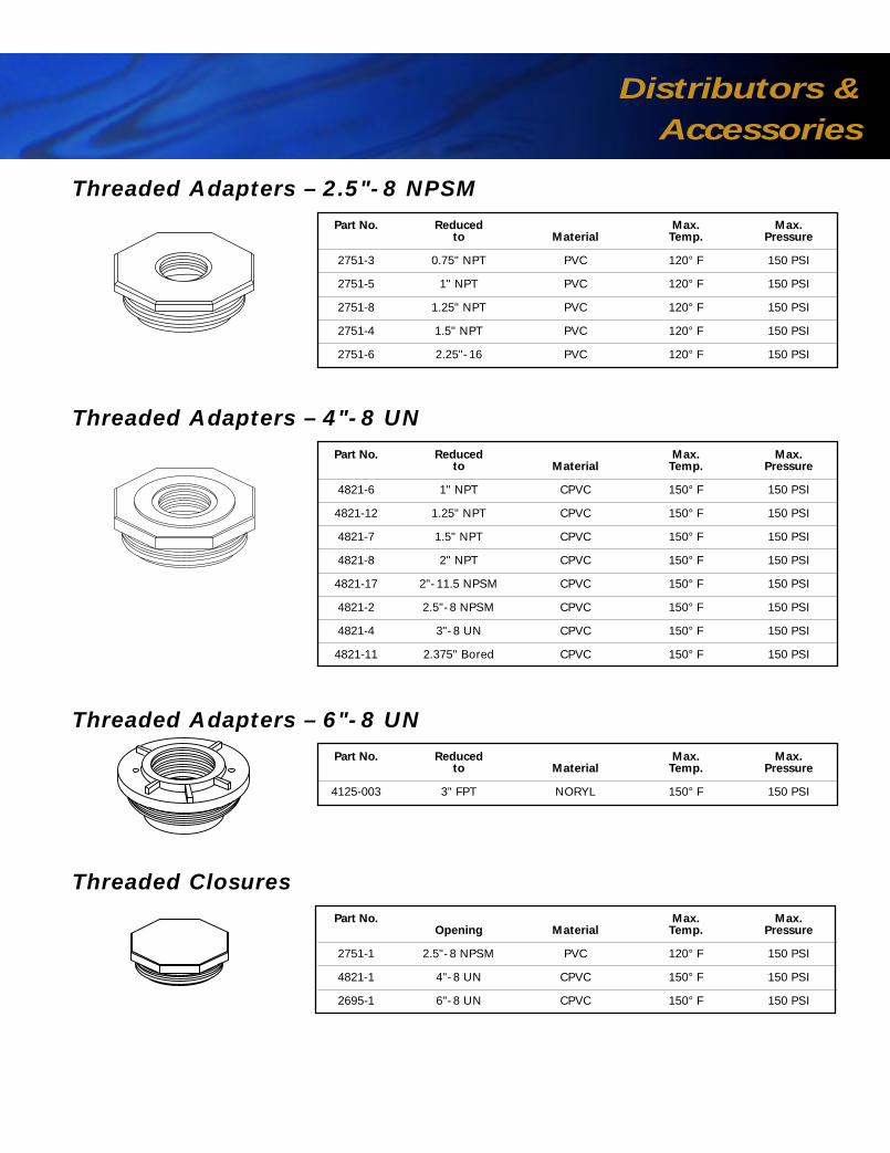
Distributors &
Accessories
Upper Flow Rate 130 GPMLower Flow Rate 170 GPM
Upper Flow Rate 130 GPMLower Flow Rate 170 GPM
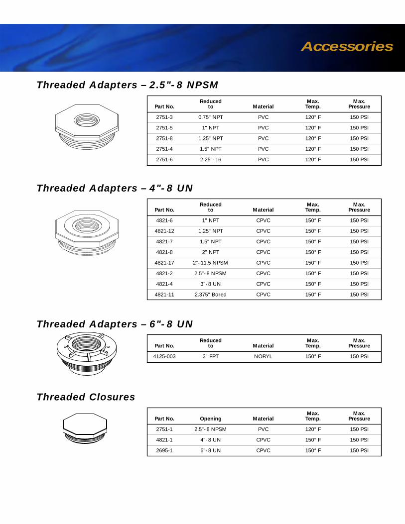
Threaded Adapters – 2.5"- 8 NPSMPart No. Reduced Max. Max.
to Material Temp. Pressure
2751-3 0.75" NPT PVC 120° F 150 PSI
2751-5 1" NPT PVC 120° F 150 PSI
2751-8 1.25" NPT PVC 120° F 150 PSI
2751-4 1.5" NPT PVC 120° F 150 PSI
2751-6 2.25"- 16 PVC 120° F 150 PSI
Threaded Adapters – 4"- 8 UNPart No. Reduced Max. Max.
to Material Temp. Pressure
4821-6 1" NPT CPVC 150° F 150 PSI
4821-12 1.25" NPT CPVC 150° F 150 PSI
4821-7 1.5" NPT CPVC 150° F 150 PSI
4821-8 2" NPT CPVC 150° F 150 PSI
4821-17 2"- 11.5 NPSM CPVC 150° F 150 PSI
4821-2 2.5"- 8 NPSM CPVC 150° F 150 PSI
4821-4 3"- 8 UN CPVC 150° F 150 PSI
4821-11 2.375" Bored CPVC 150° F 150 PSI
Threaded Adapters – 6"- 8 UNPart No. Reduced Max. Max.
to Material Temp. Pressure
4125-003 3" FPT NORYL 150° F 150 PSI
Threaded ClosuresPart No. Max. Max.
Opening Material Temp. Pressure
2751-1 2.5"- 8 NPSM PVC 120° F 150 PSI
4821-1 4"- 8 UN CPVC 150° F 150 PSI
2695-1 6"- 8 UN CPVC 150° F 150 PSI

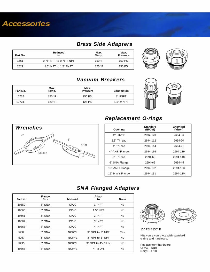
Part No. Reduced Max. Max.to Temp. Pressure
1661 0.75" NPT to 0.75" FNPT 150° F 150 PSI
2829 1.5" NPT to 1.5" FNPT 150° F 150 PSI
Vacuum BreakersPart No. Max. Max.
Temp. Pressure Connection
10725 150° F 150 PSI 1" FNPT
10724 120° F 125 PSI 1.5" MNPT
Standard ChemicalOpening (EPDM) (Viton)
2" Elbow 2694-120 2694-36
2.5" Thread 2694-112 2694-20
4" Thread 2694-114 2694-21
4" ANSI Flange 2694-136 2694-139
6" Thread 2694-68 2694-148
6" SNA Flange 2694-69 2694-45
10" ANSI Flange 2694-132 2694-133
16" MWY Flange 2694-131 2694-130
Replacement O-ringsReplacement O-rings
SNA Flanged AdaptersPart No. Flange Adapt
Size Material to Drain
10659 6" SNA CPVC 1" NPT No
10660 6" SNA CPVC 1.5" NPT No
10661 6" SNA CPVC 2" NPT No
10662 6" SNA CPVC 3" NPT No
10663 6" SNA CPVC 4" NPT No
5292 6" SNA NORYL 3" NPT to 3" NPT Yes
5267 6" SNA NORYL 3" NPT to 3" NPT No
5295 6" SNA NORYL 3" NPT to 4"- 8 UN No
10566 6" SNA NORYL 4"- 8 UN No
150 PSI / 150° F
Kits come complete with standard o-ring and hardware.
Replacement hardware:CPVC – 5310Noryl – 4750
6568-2
7729
4"
6"
Wrenches
Distributors &
Accessories

Accessories
ANSI Flanged AdaptersPart No. Flange
Size Material Adapt to
5276 4" ANSI CPVC 3" NPSM
10673 4" ANSI CPVC 2" NPT
10674 4" ANSI CPVC 3" NPT
11929 10" ANSI CPVC 4" NPT
11930 10" ANSI CPVC 6" NPT
Part No. FlangeSize Material
5296 6" SNA NORYL
10658 6" SNA CPVC
5259 4" ANSI CPVC
10472 4" ANSI Acrylic
10139 10" ANSI CPVC
Closures
Manway Closures/AdaptersPart No. Reduced Max. Max.
Opening to Material Temp. Pressure
10108 16" MWY 1-1/4" NPT Vinylester 150° F 150 PSI
14644 16" MWY 3" NPT to 3" NPT Vinylester 150° F 150 PSI
10582 16" MWY 2" NPT CPVC 150° F 100 PSI
10583 16" MWY 3" NPT CPVC 150° F 100 PSI
10584 16" MWY 4" NPT CPVC 150° F 100 PSI
11294 16" MWY 3" NPT to 3" NPT CPVC 150° F 100 PSI
11295 16" MWY 4" NPT to 4" NPT CPVC 150° F 100 PSI
5294 16" MWY 2" NPT Stainless 150° F 150 PSI
Connector Accessories
Kits come complete with standard o-ring and hardware.
Replacement hardware:4" – 5257 10" – 5754
Kits come complete with standard o-ring and hardware.
Kits come complete with standard o-ring and hardware.
Replacement hardware: 10107
Flexible Assembly (NPT - NPT)
5285 2" NPT x 2" NPT
5286 3" NPT x 3" NPT
Flexible Assembly (Flanged)
5239 4" Flanged to 3" NPT (CPVC) 150 psi/150° F
Connector
5045 3" NPSM x 3" NPT (CPVC)
Elbow
5201 2" NPSM to 2" Slip (CPVC) 150 psi/150° F
Kits come complete with standard o-ring and hardware (if required).
Wrenches
Distributors &
AccessoriesAccessories
Bottom Mount High FlowDiameter Bottom Part No. System Flow Rate(Inches) Open Composite Connection (GPM)
36 6" FLG 11892 3" FNPT 167
42 6" FLG 11663 3" FNPT 167
48 6" FLG 11665 3" FNPT 167
63 6" FLG 14248 3" FNPT 175
Bottom Mount FishboneDiameter Bottom Part No. System Flow Rate(Inches) Open Composite Connection (GPM)
63 6" FLG 5687 3" FNPT 170
Combination Kit 63"Top Side Inlet/Bottom Outlet
Size Bottom Top Top Side System Bottom System(Inches) Opening Opening Side Part No. Connection Connection
63 x 86 6" FLG 16" MWY 4" FLG 11190 3" MNPT 3" FNPT
63 x 116 6" FLG 16" MWY 4" FLG 11192 3" MNPT 3" FNPT
63 x 144 6" FLG 16" MWY 4" FLG 11194 3" MNPT 3" FNPT
Combination Kit 63"Top Side Inlet/Bottom Side Outlet
Size Bottom Top Top Bottom Side System Bottom System(Inches) Opening Opening Side Side Part No. Connection Connection
63 x 86 6" FLG 16" MWY 4" FLG 4" FLG 11191 3" MNPT 3" FNPT
63 x 116 6" FLG 16" MWY 4" FLG 4" FLG 11193 3" MNPT 3" FNPT
63 x 144 6" FLG 16" MWY 4" FLG 4" FLG 11195 3" MNPT 3" FNPT
Upper Flow Rate 130 GPMLower Flow Rate 170 GPM
Upper Flow Rate 130 GPMLower Flow Rate 170 GPM
Note: Flow rates calculated with a 5 psi pressure drop.
Threaded Adapters – 2.5"- 8 NPSMReduced Max. Max.
Part No. to Material Temp. Pressure
2751-3 0.75" NPT PVC 120° F 150 PSI
2751-5 1" NPT PVC 120° F 150 PSI
2751-8 1.25" NPT PVC 120° F 150 PSI
2751-4 1.5" NPT PVC 120° F 150 PSI
2751-6 2.25"- 16 PVC 120° F 150 PSI
Threaded Adapters – 4"- 8 UNReduced Max. Max.
Part No. to Material Temp. Pressure
4821-6 1" NPT CPVC 150° F 150 PSI
4821-12 1.25" NPT CPVC 150° F 150 PSI
4821-7 1.5" NPT CPVC 150° F 150 PSI
4821-8 2" NPT CPVC 150° F 150 PSI
4821-17 2"- 11.5 NPSM CPVC 150° F 150 PSI
4821-2 2.5"- 8 NPSM CPVC 150° F 150 PSI
4821-4 3"- 8 UN CPVC 150° F 150 PSI
4821-11 2.375" Bored CPVC 150° F 150 PSI
Threaded Adapters – 6"- 8 UNReduced Max. Max.
Part No. to Material Temp. Pressure
4125-003 3" FPT NORYL 150° F 150 PSI
Threaded ClosuresMax. Max.
Part No. Opening Material Temp. Pressure
2751-1 2.5"- 8 NPSM PVC 120° F 150 PSI
4821-1 4"- 8 UN CPVC 150° F 150 PSI
2695-1 6"- 8 UN CPVC 150° F 150 PSI
AccessoriesAccessories
Brass Side AdaptersReduced Max. Max.
Part No. to Temp. Pressure
1661 0.75" NPT to 0.75" FNPT 150° F 150 PSI
2829 1.5" NPT to 1.5" FNPT 150° F 150 PSI
Vacuum BreakersMax. Max.
Part No. Temp. Pressure Connection
10725 150° F 150 PSI 1" FNPT
10724 120° F 125 PSI 1.5" MNPT
Standard ChemicalOpening (EPDM) (Viton)
2" Elbow 2694-120 2694-36
2.5" Thread 2694-112 2694-20
4" Thread 2694-114 2694-21
4" ANSI Flange 2694-136 2694-139
6" Thread 2694-68 2694-148
6" SNA Flange 2694-69 2694-45
10" ANSI Flange 2694-132 2694-133
16" MWY Flange 2694-131 2694-130
Replacement O-ringsReplacement O-rings
SNA Flanged AdaptersFlange Adapt
Part No. Size Material to Drain
10659 6" SNA CPVC 1" NPT No
10660 6" SNA CPVC 1.5" NPT No
10661 6" SNA CPVC 2" NPT No
10662 6" SNA CPVC 3" NPT No
10663 6" SNA CPVC 4" NPT No
5292 6" SNA NORYL 3" NPT to 3" NPT Yes
5267 6" SNA NORYL 3" NPT to 3" NPT No
5295 6" SNA NORYL 3" NPT to 4"- 8 UN No
10566 6" SNA NORYL 4"- 8 UN No
150 PSI / 150° F
Kits come complete with standard o-ring and hardware.
Replacement hardware:CPVC – 5310Noryl – 4750
Wrenches
7729
6568-2
4"
6"
ANSI Flanged AdaptersFlange
Part No. Size Material Adapt to
5276 4" ANSI CPVC 3" NPSM
10673 4" ANSI CPVC 2" NPT
10674 4" ANSI CPVC 3" NPT
11929 10" ANSI CPVC 4" NPT
11930 10" ANSI CPVC 6" NPT
FlangePart No. Size Material
5296 6" SNA NORYL
10658 6" SNA CPVC
5259 4" ANSI CPVC
10472 4" ANSI Acrylic
10139 10" ANSI CPVC
Closures
Manway Closures/AdaptersReduced Max. Max.
Part No. Opening to Material Temp. Pressure
10108 16" MWY 2" NPT Vinylester 150° F 150 PSI
14644 16" MWY 3" NPT to 3" NPT Vinylester 150° F 150 PSI
10582 16" MWY 2" NPT CPVC 150° F 100 PSI
10583 16" MWY 3" NPT CPVC 150° F 100 PSI
10584 16" MWY 4" NPT CPVC 150° F 100 PSI
11294 16" MWY 3" NPT to 3" NPT CPVC 150° F 100 PSI
11295 16" MWY 4" NPT to 4" NPT CPVC 150° F 100 PSI
5294 16" MWY 2" NPT Stainless 150° F 150 PSI
Connector Accessories
Kits come complete with standard o-ring and hardware.
Replacement hardware:4" – 5257 10" – 5754
Kits come complete with standard o-ring and hardware.
Kits come complete with standard o-ring and hardware.
Replacement hardware: 10107
Flexible Assembly (NPT - NPT)
5285 2" NPT x 2" NPT
5286 3" NPT x 3" NPT
Flexible Assembly (Flanged)
5239 4" Flanged to 3" NPT (CPVC) 150 psi/150° F
Connector
5045 3" NPSM x 3" NPT (CPVC)
Elbow
5201 2" NPSM to 2" Slip (CPVC) 150 psi/150° F
Kits come complete with standard o-ring and hardware (if required).