structural design of a lunar habitat - rutgers school of ...coebenaroya/publications/ruess et al...
TRANSCRIPT

Structural Design of a Lunar HabitatF. Ruess1; J. Schaenzlin2; and H. Benaroya3
Abstract: A lunar base is an essential part of all the new space exploration programs because the Moon is the most logical firstdestination in space. Its hazardous environment will pose challenges for all engineering disciplines involved. A structural engineer’sapproach is outlined in this paper, discussing possible materials and structural concepts for second-generation construction on the Moon.Several different concepts are evaluated and the most reasonable is chosen for a detailed design. During the design process, differentsolutions—for example, for the connections—were found. Although lunar construction is difficult, the proposed design offers a relativelysimple structural frame for erection. A habitat on the Moon can be built with a reasonable factor of safety and existing technology. Evenso, we recognize the very significant difficulties that await our return to the Moon.
DOI: 10.1061/�ASCE�0893-1321�2006�19:3�133�
CE Database subject headings: Structural design; Moon; Space construction.
Introduction
Mankind set foot on the Moon over three decades ago. Ever sincethen, National Aeronautics and Space Agency �NASA� and otherspace agencies have planned to build an outpost on the Moon forevolving reasons. Was it to initially show the technical advancesof the United States during the Cold War? Today’s reasons for abase on the Moon are more practical: Astronomy, mining, or tour-ism are possible arguments for the human presence on Earth’sonly natural satellite.
On January 14th, 2004, President George W. Bush announceda new course in America’s space program. After completing theInternational Space Station by 2010, the Space Shuttle will beretired. The next generation of space vehicles will be the CrewExploration Vehicle, ready for flight by 2014. This new vehiclewill enable a return to the Moon, and future explorations beyond,as early as 2015. The extended human presence on the Moon willenable astronauts to develop new technologies and harness theMoon’s abundant resources to allow manned exploration of morechallenging environments. A human presence on the Moon couldalso reduce the cost of further exploration, since lunar-basedspacecraft could escape the Moon’s lower gravity using less en-ergy at less cost than Earth-based vehicles. The experience andknowledge gained on the Moon will serve as a foundation forhuman missions beyond the Moon, beginning with Mars.
Other nations have plans to visit the Moon as well. The Chi-nese lunar program, named Chang’e after a legendary Chinese
1Institute for Structural Design, Univ. of Stuttgart, Pfaffenwaldring 7,70569 Stuttgart, Germany.
2Institute for Structural Design, Univ. of Stuttgart, Pfaffenwaldring 7,70569 Stuttgart, Germany.
3Dept. of Mechanical and Aerospace Engineering, Rutgers Univ., 98Brett Rd., Piscataway, NJ 08854. E-mail: [email protected]
Note. Discussion open until December 1, 2006. Separate discussionsmust be submitted for individual papers. To extend the closing date byone month, a written request must be filed with the ASCE ManagingEditor. The manuscript for this paper was submitted for review and pos-sible publication on July 6, 2004; approved on March 22, 2005. Thispaper is part of the Journal of Aerospace Engineering, Vol. 19, No. 3,
July 1, 2006. ©ASCE, ISSN 0893-1321/2006/3-133–157/$25.00.JO
goddess who flew to the Moon, aims to eventually place an un-manned vehicle on the Moon by 2010. Plans also call for a ve-hicle to land by 2020 that would collect soil samples and conductother tests, possibly in preparation for a manned lunar base.
The European Space Agency’s Aurora Program also aims toset out a strategy for Europe’s solar system exploration over thenext 30 years that eventually includes manned expeditions to theMoon and Mars. A human mission to the Moon, proposed for2024, would demonstrate key life-support and habitation tech-nologies, as well as aspects of crew performance and adaptationto a long-distance space flight.
One part of these ambitious visions will be the construction ofa lunar base. This work summarizes the lunar environmental con-ditions, a classification of structural concepts being considered forlunar habitats, the preliminary and structural design of a possiblelunar base, the construction process, and challenges for futureresearch. More details can be found in the first writer’s Master’sthesis �Ruess 2004�.
Reasons to Go to the Moon
Why do we need to go to the Moon? Many researchers believerobotic exploration is the best way to conduct most space science.Others disagree. Only humans can properly investigate otherworlds, they say, to answer the most pressing questions about theorigin and fate of humans and the possibility that life exists else-where �Chang 2004�.
For many space visionaries and practical scientists alike,human spaceflight is about to open up profitable commercial op-portunities and, perhaps more importantly, continue the immu-table human desire to explore. All of these issues are discussedextensively in the literature. The list below is representative; how-ever, there are many more references available than given here.
Here are some of the top reasons for going back to the Moon.
Accessibility
The Moon is in orbit around Earth at an average distance of233,000 miles. This relatively small distance means that we can
reach the Moon with modified existing rocket systems. A trip toURNAL OF AEROSPACE ENGINEERING © ASCE / JULY 2006 / 133
the Moon takes only about three days using existing propulsiontechnology and teleoperating is possible; the radio delay timebeing within seconds �Schrunk 2002�.
Inspiration
Beyond the basic needs for food, shelter, and clothing, we hu-mans are a restless lot. The desire to explore and understand ispart of our character. The quest for knowledge is one of the mo-tivators in the desire to venture across land, sea, air, or cosmicfrontiers. A settlement on the Moon would greatly stimulate theinterest of our young in science and engineering �Eckhart 1999�.
International Cooperation
Just as the International Space Station packed explorers from pre-viously antagonistic nations into tight quarters, an effort to returnto the Moon could bring nations together in an era of increasinginternational tension.
There are several reasons why a lunar base project should bean international effort. First, any efforts by nations to do it alonewould be unnecessarily redundant and limited in scope. Second, itis the intention of the ratified outer space treaties that space de-velopment should be a peaceful effort for the benefit of all people.Third, cooperation among nations on lunar base planning, con-struction, operations, and growth has the potential to create andreinforce peaceful relations among nations.
China, with its own lunar ambitions, is a good example of acountry the United States might want to work with more closely�Benaroya 1998�.
Geology
The Apollo era answered many questions about the Moon. How-ever, much was left undone or needs to be revived.
The Moon is the attic of Earth, a place where rocks blastedlong ago from our planet are sitting around waiting to be studied.The history etched in these rocks has not decayed much becausethere is no atmosphere and little geological activity on the Moon.
A lunar base could be designed that would benefit not justplanetary scientists who want to study lunar rocks, but a widerange of sciences, such as biology, physics, paleontology, plan-etary science, historical geology, and even exobiology. Thisknowledge will lead to new insights in the fields of psychologyand sociology �Duke and Benaroya 1993; Johnson et al. 1995�.
Study Asteroid Threat
The Moon’s nearly pristine state means billions of years of aster-oid impacts are preserved, as obvious scars on the surface. Thesecraters hold a record of how frequently and intensely the innersolar system, including Earth, was hit by asteroids through time.
Studying many of these craters up close would allow scientiststo figure out if mass extinctions on Earth, including the death ofdinosaurs, that allowed the rise of mammals, were the result ofsingle large asteroid impacts, flurries of smaller assaults, or nei-ther. An answer would impact many scientific fields.
A human presence on the Moon would also be the beginningof a long-range program to ensure the survival of our species
�Benaroya 2002�.134 / JOURNAL OF AEROSPACE ENGINEERING © ASCE / JULY 2006
Astronomy
Astronomers would love to set up observatories on the Moon.Optical telescopes could be placed almost anywhere on the lunarsurface and, since there is no atmosphere to scatter light, theywould get clear Hubble-type views of the cosmos. Astronomerscould build scopes that are far larger than Hubble is, as well. Atthe same time, they could be shielded from radiation and otherhazards that plague telescopes in the Earth’s orbit.
Radio telescopes could be placed on the far side of the Moon.There they would be shielded from all the radio noise of Earth�Chua et al. 1990�.
Energy Production
Sunlight that reaches the lunar surface is constant, predictable,and inexhaustible, and can be converted into electric power bysolar panels. Several sites around the South Pole of the Moonalways have Earth in view for continuous communications, andreceive over 300 days of sunlight per year. The temperature dif-ference between the sunlight and dark areas of the Moon can alsobe used for the operation of heat engines and for thermal man-agement systems. The produced power could be beamed to Earthor to satellites for distribution around the world, 24 h a day/7 daysa week, greatly decreasing Earth’s dependence on fossil fuels. Alunar power station will not be built in a day, but a return to theMoon ought to include plans to eventually route power backhome �Spudis 2003; O’Dale 1994�.
Resources
The Moon has a wealth of raw materials. Lunar regolith containsiron, aluminum, silicon, titanium, oxygen, and traces of hydrogen,carbon, helium3, and nitrogen. Gaining experience and masteringthe necessary technology to extract these might then allow a lunarcolony to become self-sufficient or even export resources toEarth.
The Moon may also have water, frozen in dark polar craters. Ifso, it could be converted to rocket fuel, turning the Moon into abase for all other solar system exploration �Happel 1993; Spudis2003�.
Technology
Space exploration induces technology and health care spin-offsthat benefit economies and societies. The construction of the firstlunar base will provide business opportunities and jobs for peopleon Earth in many diverse fields, such as aerospace, robotics, andenvironmental sciences.
A lunar base would also serve as a test bed for the “spacefaring” technologies, such as in situ resource utilization, electro-magnetic propulsion, life-support systems, and power beaming,required to place humans on Mars and beyond.
Commercialization
There is no agreement among scientists over the role that privateenterprise ought to play in human spaceflight. Yet already, com-panies help build the machines that carry astronauts into space. Infact, investor-financed commercial enterprises already surpass theexpenditures of governments on space objects.
The lunar surface could serve as scenery for movies, adver-
tisements, and video games. Space tourism and certain mining
and manufacturing will succeed in space if only entrepreneurs areturned loose �and perhaps assisted with federal money or incen-tives�. 3He �helium3 is a very rare helium isotope� mining couldsolve energy problems for generations once nuclear fusion tech-nology becomes practical. And the demand for trips into space isthere, so entrepreneurs have started to provide the supply�Benaroya 1998; O’Dale 1994�.
Steppingstone to Mars
Lifting heavy spacecraft and fuel out of the Earth’s gravity isexpensive. Spacecraft assembled and provisioned on the Mooncould escape its lower gravity using far less energy and thus farless cost. With the experience and knowledge gained on theMoon, we will then be ready to take the next steps of spaceexploration: Human missions to Mars and beyond �Dubbink2001�.
Lunar Environment
Environmental Conditions
GravityOn the Moon, gravity is 1 /6 g. That means a structure will have,in gross terms, six times the weight bearing capacity on the Moonas on Earth; the structural dead loads will be reduced by 5/6compared to the ones on Earth. Mass-based rather than weight-based criteria are recommended to maximize the utility of con-cepts developed for lunar structural design �Benaroya et al. 2002�.
Internal Air PressurizationThe lunar structure is in fact a life-supporting closed environ-ment. Generally, the optimum habitat internal pressure is Earth’satmospheric pressure, but the pressure differential between theextravehicular activity �EVA� suits and the habitat should beminimized for safety reasons. Much like scuba diving, the dan-gerous aspect of changing pressures is the formation and expan-sion of gas bubbles in the blood and lungs. Historical internalpressures used for NASA programs have ranged from 34.5 kPa�5 psi; 21,300 kg/m2 on the Moon� to 101.4 kPa �14.7 psi;62,600 kg/m2� to provide a livable environment for theastronauts.
The habitat module pressure and the pressure used in spacesuits for EVA influence one another. EVA productivity increaseswith the use of lower pressures because the gloves become moreflexible �Elrod 1995�. At the same time, low pressures increasethe fire hazard, and lower voice and cough mechanism effective-ness for astronauts. It is assumed that the actual habitat pressurewill be around 69 kPa �10 psi; 42,600 kg/m2�. The enclosurestructure must contain this pressure, and must be designed to befailsafe against catastrophic and other decompression.
Radiation/ShieldingA prime consideration in the design is that the structure must beable to shield against the types of hazards found on the lunarsurface: Continuous solar/cosmic radiation, meteoroid impacts,extreme variations in temperature, and radiation.
There are two kinds of incoming radiation on the lunar sur-face: Electromagnetic radiation and ionizing radiation. These par-ticles interact with the Moon in different ways, resulting in
penetration depths that vary from micrometers to meters. AnyJO
kind of lunar surface habitat will have to be protected from threedifferent kinds of ionizing radiation in space: Solar wind, solarcosmic rays, and galactic cosmic radiation.
Meteoroids are naturally occurring small solid bodies travelingthrough space at very high speeds.
Most likely, a layer of compacted regolith will be placed atopthe structure for protection against all of those hazards. It pro-vides shielding against most micrometeoroid impacts because therelatively dense and heavy regolith absorbs the kinetic energy. Itappears that at least 2.5 m of regolith cover would be required tokeep the annual dose of radiation at 5 rem, which is the allowablelevel for radiation workers. In addition, it greatly reduces theeffects of the extreme temperature cycles. The mass of regolith isabout 1.7 g/cm3. With an assumed regolith cover of 3 m, theresulting dead load on the structure will be 5,100 kg/m2.
Other shielding concepts include passive bulk shielding withmaterial other than regolith, electromagnetic shielding, electro-static shielding, and chemical radioprotection.
VacuumA hard vacuum surrounds the Moon. This will preclude the use ofcertain materials that may not be stable if exposed under suchconditions. Outgassing materials and structures, e.g., hydraulicsystems, have to be avoided. A lunar structure will not be sub-jected to any kind of wind loads.
DustThe lunar surface has a layer of fine particles that is easily dis-turbed and placed into suspension. These particles cling to allsurfaces, are highly abrasive, and pose serious challenges in theutility of construction equipment and the operation and mainte-nance of airlocks �Benaroya and Ettouney 1992a,b�.
MoonquakesThere is little or no seismic activity on the Moon. Therefore, lunarstructural design will not include earthquakelike loads.
TemperatureTemperatures on the lunar surface rapidly change from approxi-mately 100 to −150°C in the transition between day and night,which occurs in roughly two-week cycles.
Structural Requirements
Building a structure on the Moon results in many different andadditional requirements that have to be fulfilled by the structure.
Structural AdequacyThe structure must sustain all dead and live loads with an accept-able degree of safety. A minimum of structural material is desired.The use of lightweight high stiffness to weight ratio materials isnecessary.
Material PropertiesProperties for lunar construction materials should include highstrength, ductility, durability, stiffness, and tear and puncture re-sistance, together with low thermal expansion. The stability ofthese mechanical properties and low leakage are important.
MaintenanceUpkeep, inspection, maintenance, and repairs have to be kept at a
minimum.URNAL OF AEROSPACE ENGINEERING © ASCE / JULY 2006 / 135

FunctionalityA low ratio of internal volume to usable floor area will ensure thatthe habitat efficiently and economically houses and supports theoperations for which it is designed.
CompatibilityThe structure must be designed for compatibility with the internalenvironment, heat management, and rejection, as well as othersupport systems.
TransportationSmall stowage volume and light mass minimize transportationcosts and volume.
Ease of ConstructionThe remoteness of the lunar site, in conjunction with the highcosts associated with launches from Earth, suggests that lunarstructures should be designed for ease of construction so that theEVA of the astronaut construction team is minimized. Construc-tion components must be practical �easy connections of structuralcomponents� and, in a sense, modular in order to minimize localfabrication and needed construction equipment. Single compo-nents should be designed to be handled by one or at most twoastronauts. Easy handling and moving of the regolith used forshielding cover can be achieved by bagging it. Robotic and auto-mated construction methods are desirable, but cannot be assumedto exist in the near future.
ExcavationGrading and excavation are difficult and expensive because of thelack of traction and the locking nature of the regolith. Designsolutions that keep excavation at a minimum need to befound. The use of footing pads might be a solution to eliminateexcavation.
FoundationsLarge and complicated foundations will not be feasible in thebeginning. This is because regolith/soil mechanics are not fullyunderstood yet, and the transport and use of heavy constructionequipment is very expensive. Footing pads might once again bethe solution for early applications.
Use of Local MaterialsThis is to be considered extremely important in the long-termview of extraterrestrial habitation. However, feasibility will haveto wait until a minimal presence has been established on theMoon.
Materials
Metals
SteelSteel can be cast either directly to shape, or into ingots that arereheated and hot worked into a wrought shape by forging, extru-sion, rolling, or other processes. Wrought steels are the most com-mon engineering material used, and come in a variety of formswith different finishes and properties.
According to the chemical composition, standard steels can beclassified into three major groups: carbon steels, alloy steels, and
stainless steels. Carbon steel is what is most commonly used for136 / JOURNAL OF AEROSPACE ENGINEERING © ASCE / JULY 2006
construction all over the world as a relatively cheap and effectivematerial. Because of that, engineers probably have the most ex-perience with this material, and many applications can be modi-fied to suit lunar construction. However, for lunar applications,the specific weight of the material is very high and there-fore makes transport to the Moon very expensive and maybeineffective.
AluminumAluminum is a very versatile metal and can be cast in any formknown. It can be rolled, stamped, drawn, spun, roll-formed, ham-mered, and forged. The metal can be extruded into a variety ofshapes, and can be turned, milled, and bored in the machiningprocess. Aluminum can be riveted, welded, brazed, or resinbonded.
At extremely high temperatures �200–250°C� aluminum al-loys tend to lose some of their strength. However, at subzerotemperatures, their strength increases while retaining their ductil-ity, making aluminum an extremely useful low-temperature alloy.
TitaniumTitanium is 40% lighter than steel and 60% heavier than alumi-num. Its combination of high strength and low weight makestitanium a very useful structural metal. It is used in a variety ofapplications, including products where weight is of importance,such as aircraft.
Titanium is rather difficult to fabricate because of its suscep-tibility to oxygen, nitrogen, and hydrogen impurities that causethe titanium to become more brittle. Elevated temperature pro-cessing must be used under special conditions in order to avoiddiffusion of these gasses into the titanium. Commercially pro-duced titanium products are made in the following mill wroughtforms; plate, tubing, sheet, wire, extrusions, and forgings. Tita-nium can also be cast, which must be done in a vacuum furnacebecause of its reactive nature. All of the problems in fabricationmake titanium products quite expensive. However, its lower spe-cific weight might enable it to compete with steel, if transportcosts are taken into account.
MagnesiumMagnesium is among the lightest of all the metals, and the sixthmost abundant on Earth. Magnesium is ductile and the most ma-chinable of all the metals. Due to its lightweight, superior ma-chinability, and ease of casting, magnesium is used for manypurposes, such as auto parts, power tools, sporting goods, aero-space equipment, fixtures, and material handling equipment. Au-tomotive applications include gearboxes, valve covers, wheels,clutch housings, and brake pedal brackets. Wrought alloys areavailable in rod, bar, sheet, plate, forgings, and extrusions.
Fabrics
Fabrics for membranes, for example, are manufactured using fi-bers; weaving them into a canvas and finally coating them forprotection. Among the fibers used in textile construction are poly-ester, glass, polytetrafluoroethylene �PTFE�, nylon and Kevlar fi-bers. Again, Kevlar is the most suited for lunar applications sinceit has the highest strength combined with low self-weight. Thefinal fabric properties, especially tear resistance, depend on theway the chain and shoot directions were interwoven. For coating,mainly polyvinylchloride and PTFE are used. Polyethylenemembranes will most likely not be used because they develop
poisonous gases in case of a fire accident. Layered membrane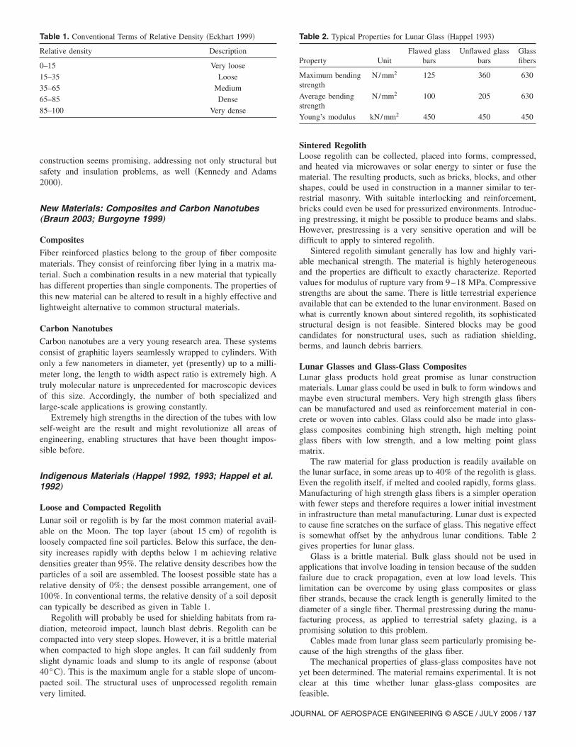
construction seems promising, addressing not only structural butsafety and insulation problems, as well �Kennedy and Adams2000�.
New Materials: Composites and Carbon Nanotubes„Braun 2003; Burgoyne 1999…
CompositesFiber reinforced plastics belong to the group of fiber compositematerials. They consist of reinforcing fiber lying in a matrix ma-terial. Such a combination results in a new material that typicallyhas different properties than single components. The properties ofthis new material can be altered to result in a highly effective andlightweight alternative to common structural materials.
Carbon NanotubesCarbon nanotubes are a very young research area. These systemsconsist of graphitic layers seamlessly wrapped to cylinders. Withonly a few nanometers in diameter, yet �presently� up to a milli-meter long, the length to width aspect ratio is extremely high. Atruly molecular nature is unprecedented for macroscopic devicesof this size. Accordingly, the number of both specialized andlarge-scale applications is growing constantly.
Extremely high strengths in the direction of the tubes with lowself-weight are the result and might revolutionize all areas ofengineering, enabling structures that have been thought impos-sible before.
Indigenous Materials „Happel 1992, 1993; Happel et al.1992…
Loose and Compacted RegolithLunar soil or regolith is by far the most common material avail-able on the Moon. The top layer �about 15 cm� of regolith isloosely compacted fine soil particles. Below this surface, the den-sity increases rapidly with depths below 1 m achieving relativedensities greater than 95%. The relative density describes how theparticles of a soil are assembled. The loosest possible state has arelative density of 0%; the densest possible arrangement, one of100%. In conventional terms, the relative density of a soil depositcan typically be described as given in Table 1.
Regolith will probably be used for shielding habitats from ra-diation, meteoroid impact, launch blast debris. Regolith can becompacted into very steep slopes. However, it is a brittle materialwhen compacted to high slope angles. It can fail suddenly fromslight dynamic loads and slump to its angle of response �about40°C�. This is the maximum angle for a stable slope of uncom-pacted soil. The structural uses of unprocessed regolith remain
Table 1. Conventional Terms of Relative Density �Eckhart 1999�
Relative density Description
0–15 Very loose
15–35 Loose
35–65 Medium
65–85 Dense
85–100 Very dense
very limited.
JO
Sintered RegolithLoose regolith can be collected, placed into forms, compressed,and heated via microwaves or solar energy to sinter or fuse thematerial. The resulting products, such as bricks, blocks, and othershapes, could be used in construction in a manner similar to ter-restrial masonry. With suitable interlocking and reinforcement,bricks could even be used for pressurized environments. Introduc-ing prestressing, it might be possible to produce beams and slabs.However, prestressing is a very sensitive operation and will bedifficult to apply to sintered regolith.
Sintered regolith simulant generally has low and highly vari-able mechanical strength. The material is highly heterogeneousand the properties are difficult to exactly characterize. Reportedvalues for modulus of rupture vary from 9–18 MPa. Compressivestrengths are about the same. There is little terrestrial experienceavailable that can be extended to the lunar environment. Based onwhat is currently known about sintered regolith, its sophisticatedstructural design is not feasible. Sintered blocks may be goodcandidates for nonstructural uses, such as radiation shielding,berms, and launch debris barriers.
Lunar Glasses and Glass-Glass CompositesLunar glass products hold great promise as lunar constructionmaterials. Lunar glass could be used in bulk to form windows andmaybe even structural members. Very high strength glass fiberscan be manufactured and used as reinforcement material in con-crete or woven into cables. Glass could also be made into glass-glass composites combining high strength, high melting pointglass fibers with low strength, and a low melting point glassmatrix.
The raw material for glass production is readily available onthe lunar surface, in some areas up to 40% of the regolith is glass.Even the regolith itself, if melted and cooled rapidly, forms glass.Manufacturing of high strength glass fibers is a simpler operationwith fewer steps and therefore requires a lower initial investmentin infrastructure than metal manufacturing. Lunar dust is expectedto cause fine scratches on the surface of glass. This negative effectis somewhat offset by the anhydrous lunar conditions. Table 2gives properties for lunar glass.
Glass is a brittle material. Bulk glass should not be used inapplications that involve loading in tension because of the suddenfailure due to crack propagation, even at low load levels. Thislimitation can be overcome by using glass composites or glassfiber strands, because the crack length is generally limited to thediameter of a single fiber. Thermal prestressing during the manu-facturing process, as applied to terrestrial safety glazing, is apromising solution to this problem.
Cables made from lunar glass seem particularly promising be-cause of the high strengths of the glass fiber.
The mechanical properties of glass-glass composites have notyet been determined. The material remains experimental. It is notclear at this time whether lunar glass-glass composites are
Table 2. Typical Properties for Lunar Glass �Happel 1993�
Property UnitFlawed glass
barsUnflawed glass
barsGlassfibers
Maximum bendingstrength
N/mm2 125 360 630
Average bendingstrength
N/mm2 100 205 630
Young’s modulus kN/mm2 450 450 450
feasible.
URNAL OF AEROSPACE ENGINEERING © ASCE / JULY 2006 / 137
Cast Regolith (Cast Basalt)Cast regolith is very similar to terrestrial cast basalt. The termshave been used interchangeably in the literature to refer to thesame material. Cast regolith can be readily manufactured on theMoon by melting regolith and cooling it slowly so that the mate-rial crystallizes instead of turning into glass. Virtually no materialpreparation is needed. The casting operation is simple requiringonly a furnace, ladle, and molds.
Vacuum melting and casting should enhance the quality of theend product. More importantly, there is terrestrial experience pro-ducing the material; but it has not been used for constructionpurposes yet.
Cast basalt has extremely high compressive and moderate ten-sile strength. It can easily be cast into structural elements forready use in prefabricated construction. Feasible shapes includemost of the basic structural elements, such as beams, columns,slabs, shells, arch segments, blocks, and cylinders.
Note that the ultimate compressive and tensile strengths areeach about ten times greater than those of concrete �see Table 3�.
Cast basalt also has the disadvantage that it is a brittle mate-rial. Tensile loads that are a significant fraction of the ultimatetensile strength need to be avoided. The fracture and fatigue prop-erties need further research.
It should be feasible to use cast regolith in many structuralapplications without any tensile reinforcement because of itsmoderately high tensile strength. However, a minimum amount oftension reinforcement may be required to provide a safe structure.The reinforcement could be made with local materials.
Cast regolith is most suited for use in structures that are domi-nated by compression. However, using prestressed applicationswill offer a wide variety of shapes and structures. Prestressingtendons can be made from lunar materials.
Since it is extremely hard, cast regolith has high abrasion re-sistance. This is an advantage for use in the dusty lunar environ-ment. It may be the ideal material for paving lunar rocket launchsites and constructing debris shields surrounding landing pads.The hardness of cast basalt combined with its brittle nature makesit a difficult material to cut, drill, or machine. Such operationsshould be avoided on the Moon.
Production of cast regolith is energy intensive because of itshigh melting point.
The estimated energy consumption is 360 kW h/MT.
Lunar ConcreteThe basic materials needed for the manufacturing of lunar con-crete are the same as for concrete on Earth: Aggregate, water, andcement. Properly screened and sized lunar regolith makes high-quality concrete aggregate. Small quantities of actual lunar re-golith have been used as aggregate in the preparation of concretein the laboratory. The resulting properties for lunar concrete aregiven in Table 4.
Cement can be manufactured by beneficiating high calcium
Table 3. Typical Properties for Cast Regolith �Happel 1993�
Property Unit Value
Tensional strength N/mm2 34.5
Compressive strength N/mm2 538
Young’s modulus kN/mm2 100
Density g/cm3 3
Temperature coefficient 10−6 /K 7.5–8.5
content lunar rock. Water is not available. Once lunar oxygen
138 / JOURNAL OF AEROSPACE ENGINEERING © ASCE / JULY 2006
facilities are established, water could be produced by combininglunar oxygen with hydrogen extracted from lunar soil. Hydrogenis also a by-product of 3He mining operations. If the formworkneeded to cast concrete on the Moon could also be made fromlunar materials, then concrete could become a versatile lunar con-struction material. Furthermore, lunar concrete cannot be cast in avacuum. It has to be cast and cured in a pressurized environment,because the vacuum draws off the water needed for the chemicalreaction that hardens the concrete. Thereby, it greatly weakens thefinal product. Premixing of the dry ingredients, placing the drypowder in forms, and using steam injection to harden and cure theconcrete has been proposed to overcome the problem of castingconcrete in a vacuum. An alternative is to construct a large pres-surized concrete production facility to fabricate precast concretemodules.
Concrete is brittle and weak in tension. For most structuraluses, concrete is extensively reinforced with a high strength duc-tile material, such as steel. Lunar glass could also be used asreinforcement. Fiberglass concrete reinforcement material is gain-ing popularity on Earth.
Concrete can be cast into an infinite variety of shapes makingit a very versatile material. Civil engineers have extensive expe-rience with concrete construction on Earth. Its uses, performance,and properties are well understood and characterized.
However, the manufacturing and use of lunar cement andconcrete is a complex multistep operation. Production ofcement is also an energy intensive process. Cement requires2 ,200 kW h/MT. Establishing the infrastructure necessary to ac-complish concrete production on the surface of the Moon wouldbe an expensive, difficult, and time-consuming operation. Lunarconcrete production will only occur late in the establishment of alunar colony.
Lunar MetalsAluminum, titanium, magnesium, and iron are among the sevenmost common elements present in lunar regolith �see Fig. 1�.
These metals may be obtained as by-products of a lunar oxy-gen manufacturing operation. This would make them readilyavailable as feedstock in the manufacturing of structural shapes.Iron can be easily separated magnetically from the regolith. Al-loys can be made from the major elements—Fe, Si, Mg, Al, Ti,and Ni—and from the minor elements—Cr, Mn, Zr, and V—thatare sufficiently abundant to be useful �0.1–2%�. Some of the otherprincipal alloying elements are not found in significant quantitieson the Moon. Carbon, which is necessary to make steel, is notpresent in useful amounts and would have to be imported. Oncemanufactured, the metals and their alloys are outstanding struc-tural materials with very good tensile and compressive strengthproperties. Steel and aluminum are commonly used in structureson Earth. Their mechanical properties and their uses in terrestrialconstruction are well understood.
Excluding iron, there are no lunar equivalents of the easy to
Table 4. Typical Properties for Lunar Concrete �Happel 1993�
Property Unit Value
Compressive strength N/mm2 39–75.7
Young’s modulus kN/mm2 21.4
Ultimate strain %
Density g/cm3 2.6
Temperature coefficient 10−6 /K 5.4
refine metallic ores found on Earth. Most metals are only present

in difficult to refine compounds, primarily oxides. The oxidesmust be concentrated, and then the metals must be separated fromthe oxides, purified, melted, and alloyed. The additional steps ofcasting, drawing, and heat treatment are also usually necessary toform metal into useful structural shapes.
These operations would require establishing an extensive in-dustrial infrastructure on the Moon.
The ability to manufacture metals, such as steel and aluminum,even in small amounts would be extremely valuable for lunarindustrialization. Metals are a key ingredient for most technolo-gies and have wider uses than construction. Therefore, simplifiedmetal production technology will probably be established early inthe development of a lunar colony. Steel is the prime candidatefor early production because it can be refined with much lessenergy consumption than the other metals. Aluminum, for ex-ample, requires approximately six times as much energy to pro-duce as steel �Happel 1993�.
Material SelectionSelecting an indigenous material for design work that venturesbeyond the conceptual is necessarily a somewhat subjective pro-cess. This is because there has not been any lunar constructionand the lunar environment is very difficult to duplicate on Earth.Therefore, working experience with indigenous materials in alunar environment is nonexistent. Theory, laboratory results, andterrestrial experience must be extrapolated to the Moon. Suchextrapolation is a risky activity at best, fraught with the potentialfor overlooking a key factor or encountering the totallyunexpected.
An evaluation procedure has been proposed �Happel 1993�.The perfect indigenous construction material combining all ben-eficial qualities probably does not exist. However, cast regolithappears to have the best combination of material and manufactur-ing properties among all the indigenous materials.
Key Structural Concepts
A lunar base will go through evolutionary development, startingwith limited capacity and expanding over time.
Lunar development will stage in three main phases. In each ofthese phases, a different generation of habitats will necessarilyevolve �Happel 1993; Benaroya 2002; Cohen 2002�.1. Prefabricated and preoutfitted hard shell modules;2. Assembly of components fabricated on Earth with some as-
Fig. 1. Elemental composition of lunar regolith �wt % �
sembly required; and
JO
3. Large-scale building structures comprised substantially of in-digenous materials.
Since first-generation concepts are already well understoodand third-generation facilities are still far off, highly complex, andcan only be based on many assumptions and uncertainties, thiswork focuses on second-generation mainly prefabricated lunarbases. Second generation lunar habitats can be further dividedinto four main structural types:1. Inflatable structures;2. Cable structures;3. Rigid structures; and4. Underground construction.
InflatablesInflatable structural concepts for a lunar base are a means to speedup the construction process while lessening the costs �Roberts1988; Broad 1989�. Membrane fabrics efficiently support the in-ternal pressure loads. An unsupported inflatable will collapsefrom its own weight in the event of a loss of pressure, so thepossibility of a puncture has to be addressed in the design pro-cess. Simple membrane fabrics, such as those used on Earth, willnot be able to meet all material requirements for lunar construc-tion. Abrasion resistance, as well as resistance to all kinds ofloads during transport and construction, can only be achievedusing layered or composite solutions.
One of the major advantages of inflatable habitats may be themost difficult to qualify: Habitability. It is the sum of the qualitiesthat make an environment a pleasant place to live and a produc-tive place to work. Most inflatables not only provide a large vol-ume, they provide perceptible volume. In a modular base, aperson can never perceive �or utilize� a volume larger than that ofa single module.
Spherical Inflatable (Roberts 1988)This inflatable habitat consists of a spherical pneumatic envelopewith an interior structural cage to support the floors, walls, andequipment, and to hold up the envelope if pressure is lost �seeFig. 2�.
The sphere analyzed in �Roberts 1988�, when inflated, will be16 m in diameter, containing 2,145 m3 of open volume and594 m2 on four floors. Structural analysis is performed assumingan internal pressure of 101.4 kPa. The envelope will consist of ahigh strength multiply fabric, with an impermeable inner layerand a thermal coating on the outside. With a safety factor of 5, thestructural layer made from Kevlar 29 is to be 5 mm thick,amounting to a total mass of 2,200 kg for the structural envelope.The packaged volume will be about 40 m3. It is planned to coverthe habitat with 3 m of regolith in the form of “sandbags” �seeFig. 3�.
Placing the regolith is very labor intensive, taking up much ofthe crew’s time during the early missions. An alternative might beto provide some shielding to protect the habitat from galacticcosmic radiation, with a separate “storm shelter” to protect thecrew in the event of a serious solar flare. However, operationalsimplicity, safety, and the possibility to protect from meteoroidimpacts favor the concept of regolith shielding.
The interior structure will be a simple frame structure, support-ing the floors, equipment, and furnishings. It will also support theregolith shielding in the event of a loss of pressure. A roughestimate puts the mass of the framework at 16,300 kg. This iswhere one can easily see a problem with this concept. Whiletrying to save mass using an inflatable envelope, because of the
interior multifloor layout and the necessity to provide a secondaryURNAL OF AEROSPACE ENGINEERING © ASCE / JULY 2006 / 139

structure for the event of a pressure loss, the mass of the interiorstructure is about eight times higher than the mass of the mainstructure. Foundation issues are not addressed but must be con-sidered. Fig. 4 shows an artist’s impression of the completed base.
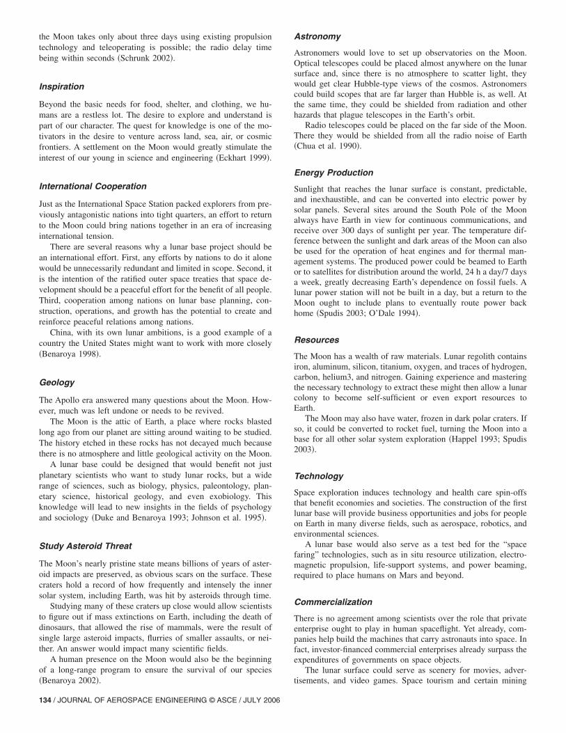
“Tuft Pillow” InflatableA pillow- or box-shaped structure is a possible concept for apermanent lunar base. The proposed base consists of quilted in-flatable pressurized tensile structures using fiber composites�Vanderbilt et al. 1988�. The foundation problem and additionalreliability concerns and analysis are considered in Nowak et al.�1990�. This concept marks a significant departure from numerousother inflatable concepts in that it shows an alternative to sphe-roidal inflatables and optimizes volume for habitation. The inflat-able structure can be used as a generic test bed structure for avariety of lunar applications �Sadeh and Criswell 1994�. Designcriteria are also put forward �Criswell et al. 1996�.
An inflated tensile membrane is the ideal structural solutionfor a pressure vessel. Fiber composite membranes are a highlyeffective material in terms of material properties and transporta-tion costs. An inflatable membrane structure offers at once theadvantages of structural efficiency and ease of construction. Theproposed structure consists of single-level identical inflatable
Fig. 2. Cross section of the spheric
Fig. 3. The habitat “sandbagged” for radiation protection �Roberts1988�
140 / JOURNAL OF AEROSPACE ENGINEERING © ASCE / JULY 2006
modules. The basic module of 6.1�6.1�2.44 m�20�20�8 ft;length�width�nominal height� consists of the following com-ponents �see also Fig. 5�:1. A roof and a subfloor membrane which are segments of a
sphere of the same radius;2. Four side wall membranes of a doubly curved prismatic
shape which approximates a spherical shape; and3. An inflatable frame system composed of four tubular tension
columns made of a thin membrane with sufficient compres-sive strength to sustain a deflated configuration and fourupper and four lower tubular compression arches also madeof a thin membrane placed in a vertical plane extendingalong the sides of the module.
The orientation of the arches in a vertical plane facilitates themodularity of the system. The frame system must be able to fullysupport the deflated unpressurized module in an open configura-tion or the unpressurized module with the regolith cover duringconstruction sequences, operation procedures, and in case of anaccident.
When two or more modules are placed together, the design ofthe common interior walls depends upon the functional designand the pressure differences among adjacent modules. The gravity
atable lunar habitat �Roberts 1988�
Fig. 4. NASA artist’s impression of the spherical inflatable base
al infl
loads induced by the regolith cover and the weight of the structureand its contents can be transferred through footings attached tothe vertical columns. This approach is desirable since it can alsobe used for the deflated configuration.
After a preliminary design, using Kevlar 49 and an internalpressure of 69 kPa �10 psi�, the total mass for a single inflatedmodule meeting all structural requirements amounts only to about195 kg �429 lb�. Additional issues that have to be addressed in adetailed design include module response to dynamic loads, air-lock operation, module interaction with outfitting equipment,module fabrication, module testing on Earth, and module con-struction on the lunar surface. Transportation and construction hasto be done very carefully to avoid damage to the membranes.High redundancy exists, for example, if the single modules orareas are connected and can be sealed off with airlocks. Compos-ite membranes cannot be produced from local materials on theMoon.
Cable StructuresCable structures can be used for all the different stages of lunarcolonization. Tension systems, including tension cables, cable re-inforced fabrics, cable nets, and cables with stiffened trusses,have been used extensively in Earth environment-based structures�Otto 1973; Buchhold 1985; Leonard 1988�. The advantages anddisadvantages of these systems, when applied to different build-ing configurations, are also well known. The most obvious reason,however, to use a cable roof system is its ability to carry theintended loads with great efficiency through axial internal tensionforces.
Lunar Crater Base (Eichold 2000)A lunar base cable structure in a crater is a concept that tries touse natural features on the Moon to reduce excavation and theamount of shielding that is needed. The scope of this concept is alarger one. Therefore, it is to be categorized somewhere betweensecond- and third-generation concepts, depending on the actualsize of the crater and the materials used. Similar roof structures,as the one proposed in Fig. 6, have been used for stadium roofsand other structures on Earth. A spoked wheel or tensegrity ar-rangement of the cables, also used for similar structures on Earth,can avoid instability in case of a pressure loss and other loadreversals. The compression ring�s� in the rim of the crater has asectional diameter large enough to permit inspection of the cableanchorage. The cover can be membranes, which will have to beimported, or thin walled metal plates, which can be made fromlunar materials. The cables can either be imported or made fromlunar material, such as lunar fiberglass. The tension ring�s� on the
Fig. 5. View of a lunar base layout using tuft-pillow inflatables�Vanderbilt et al. 1988, ASCE�
inside can be equipped with a pair of lenses that track the sunlight
JO
across the sky while optimizing the spread of light within thecrater. They can be filled with water or some other clear shieldingmaterial.
Protection from meteoroid impacts is not addressed. Glassoculus and membrane can be fused together to provide propersealing. Private, as well as public, rooms can be built in the craterwalls for example by rock melting. The crater floor can be usedfor agriculture, research, and storage, for example. Accessibilitymay be difficult. However, from a long-term human factor per-spective, this concept seems very promising.
Rigid StructuresThe most experience is available for rigid structures such astrusses, frames, and arches. A hard structural shell provides cer-tain robustness and high puncture resistance, for example. Rigidstructures can be designed to accommodate all load cases at thesame time without the need for a secondary structure, such as theinflatable structure, for example. The penalty is a generally highermass and transportation volume.
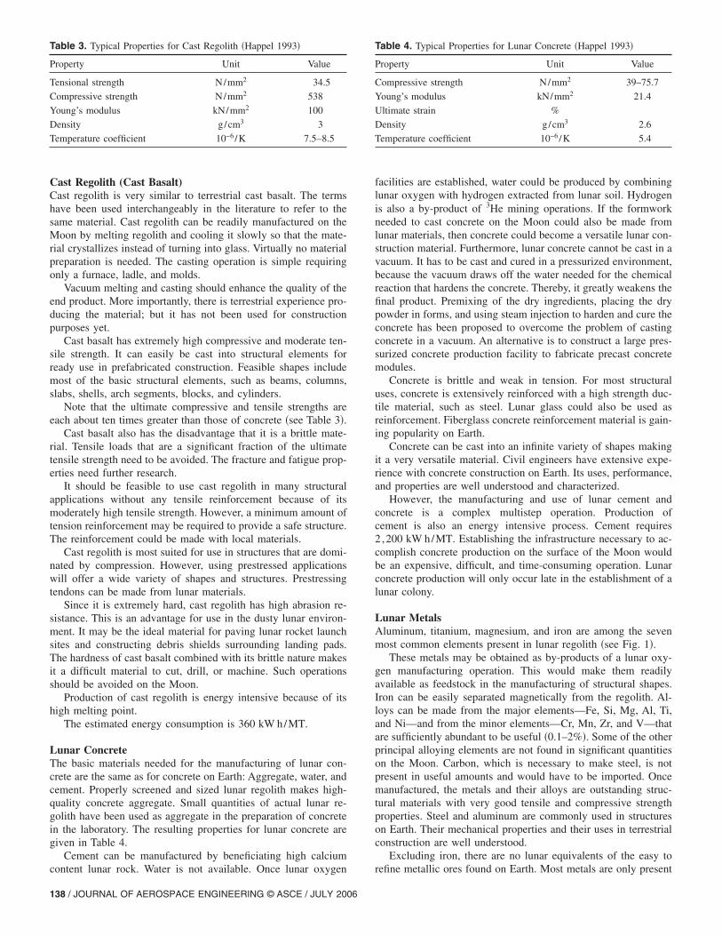
Three-Hinged Arch Shell StructureThe structure in Figs. 7 and 8 is an update of an earlier concept�Ettouney et al. 1992�. It will be discussed subsequently in detail.
Underground Construction
The geological phenomena known as the lava tube might verywell provide an alternative to lunar surface construction. Lavatubes, formed by flow channels of molten lava, are well known onEarth. It is believed that lunar lava tubes will be more frequentand much larger than their terrestrial analogs. It appears that natu-ral caverns of suitable sizes to house an entire lunar base exist onthe Moon.
Fig. 6. Possible roof structure for a lunar base �Eichold 2000, withpermission from the Space Studies Institute�
Fig. 7. Rendering of a lunar habitat module
URNAL OF AEROSPACE ENGINEERING © ASCE / JULY 2006 / 141
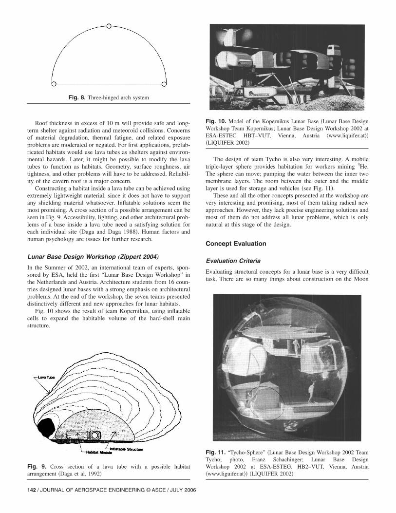
Roof thickness in excess of 10 m will provide safe and long-term shelter against radiation and meteoroid collisions. Concernsof material degradation, thermal fatigue, and related exposureproblems are moderated or negated. For first applications, prefab-ricated habitats would use lava tubes as shelters against environ-mental hazards. Later, it might be possible to modify the lavatubes to function as habitats. Geometry, surface roughness, airtightness, and other problems will have to be addressed. Reliabil-ity of the cavern roof is a major concern.
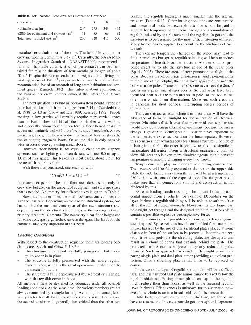
Constructing a habitat inside a lava tube can be achieved usingextremely lightweight material, since it does not have to supportany shielding material whatsoever. Inflatable solutions seem themost promising. A cross section of a possible arrangement can beseen in Fig. 9. Accessibility, lighting, and other architectural prob-lems of a base inside a lava tube need a satisfying solution foreach individual site �Daga and Daga 1988�. Human factors andhuman psychology are issues for further research.
Lunar Base Design Workshop „Zippert 2004…
In the Summer of 2002, an international team of experts, spon-sored by ESA, held the first “Lunar Base Design Workshop” inthe Netherlands and Austria. Architecture students from 16 coun-tries designed lunar bases with a strong emphasis on architecturalproblems. At the end of the workshop, the seven teams presenteddistinctively different and new approaches for lunar habitats.
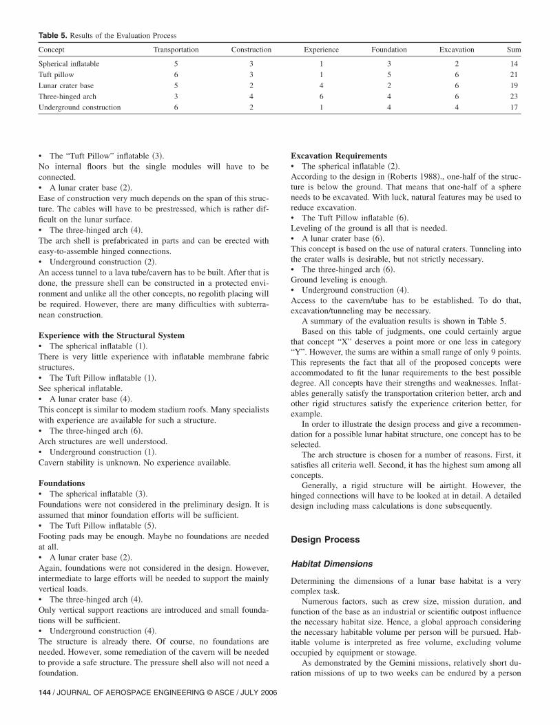
Fig. 10 shows the result of team Kopernikus, using inflatablecells to expand the habitable volume of the hard-shell mainstructure.
Fig. 8. Three-hinged arch system
Fig. 9. Cross section of a lava tube with a possible habitatarrangement �Daga et al. 1992�
142 / JOURNAL OF AEROSPACE ENGINEERING © ASCE / JULY 2006
The design of team Tycho is also very interesting. A mobiletriple-layer sphere provides habitation for workers mining 3He.The sphere can move; pumping the water between the inner twomembrane layers. The room between the outer and the middlelayer is used for storage and vehicles �see Fig. 11�.
These and all the other concepts presented at the workshop arevery interesting and promising, most of them taking radical newapproaches. However, they lack precise engineering solutions andmost of them do not address all lunar problems, which is onlynatural at this stage of the design.
Concept Evaluation
Evaluation Criteria
Evaluating structural concepts for a lunar base is a very difficulttask. There are so many things about construction on the Moon
Fig. 10. Model of the Kopernikus Lunar Base �Lunar Base DesignWorkshop Team Kopernikus; Lunar Base Design Workshop 2002 atESA-ESTEC HBT–VUT, Vienna, Austria �www.liquifer.at���LIQUIFER 2002�
Fig. 11. “Tycho-Sphere” �Lunar Base Design Workshop 2002 TeamTycho; photo, Franz Schachinger; Lunar Base DesignWorkshop 2002 at ESA-ESTEG, HB2–VUT, Vienna, Austria�www.liguifer.at�� �LIQUIFER 2002�

about which we lack knowledge. Most of the criteria given beloware also qualitative. Applying them to a structural concept has tobe done very carefully. The different criteria are not put into anyorder on purpose, because objectively weighting them is alsoquite a problem. However, it is important to make the effort torationally decide on suitable concepts for lunar design andconstruction.
The following are among the criteria for evaluating lunar baseconcepts.
TransportationThe mass and volume that has to be transported will greatly affectthe total cost.
Ease of Construction
Does the erection process of the structure need a shirtsleeve en-vironment? Simple modular connections result in less astronautconstruction time. What kind of heavy construction equipment isneeded? The use of deployable/self-erecting structures can help tominimize EVA activities �Hijazi 1988; Benaroya and Ettouney1992a,b�.
Experience with the General Structural Systemand MaterialsNumerous unknowns and variables accompany lunar construc-tion. Some of the data needed to exactly describe lunar construc-tion will only be available after a certain presence on the Moon isestablished. Therefore, it is not desirable for early concepts toinclude structural systems that themselves inherit too many un-certainties. In addition, it will be easier to react to problems aris-ing during construction on the Moon if there is experience withthe type of structure from former projects. Extensive prototypetesting can help to gain experience. Implicit here is that structuralconcepts with which we are experienced can be designed in arobust way leading to long lifetimes �Benaroya 1994�.
ExpandabilitySpecifically, the second-generation bases will have to be able toadapt to a change in use. The structure must allow adding to ormodifying the general layout �Duke and Benaroya 1993�.
ExcavationExcavation operations will require heavy machinery that has to betransported to the Moon first. Ground preparation will certainlybe needed but deeper excavations should be avoided �Graf 1988�.
FoundationsThe concrete foundations that are widely used for almost everyconstruction project on Earth will not be available for early lunarbases. New foundation types will have to be developed. Reducingor completely avoiding horizontal and tensile support reactions isessential. The maximum use of the lunar soil strength is manda-tory �Chua et al. 1990�.
Human FactorsThe structure must accommodate lighting, ventilation, insulation,and acceptable acoustics. Crew psychology and therefore effec-tiveness will greatly depend on the quality of life in the lunarhabitat. One important factor is the perceivable volume �Elrod
1995; Eichold 2000�.JO
RecyclingAs thoughts turn toward third-generation structures, deconstruc-tion and recycling of old structures will become increasinglyimportant. Structures that are easily assembled can almost auto-matically be easily disassembled. Metals are easier to recycle thancomposites, for example.
MaintenanceThe longer the desired lifespan of a lunar structure, the moreimportant the maintenance requirements. Maintenance costs cangreatly affect overall costs and will therefore have to be mini-mized. At the same time, maintenance is always necessary for asafe structures, so access to, and the easy replacement of, struc-tural components will be crucial.
Evaluation of Second-Generation Lunar HabitatConcepts
As mentioned earlier, this work focuses on second-generationstructures. It is expected that, especially for early second-generation habitats, the following criteria will govern.• Transportation;• Ease of construction;• Experience with the structural system;• Excavation; and• Foundations.
In order to evaluate some of the concepts from the precedingsection, a points system ranging from 1 to 6 is used. A value of 6represents the best performance for the given criteria; a value of1, the worst. Again, an evaluation of lunar habitat structural con-cepts cannot be 100% objective, but an effort was made here toget close. All of the assigned values are explained below and itwas assumed that the five criteria are equally important. Ofcourse, they are not; but their weighting will change with everyadvance in rocket, materials, and lunar science. So, it was decidednot to weigh the categories now. The maximum/minimum valueswere only used if the conceptual design of the given structure wasclear. A more detailed evaluation, including many other lunar baseconcepts, is available �Ruess 2004�.
Transportation• The spherical inflatable �Figs. 2 and 3� �5 points�The pressure shell yields a low mass and transportation volume,but the internal arrangement with floors, stairs, and structural ribsresults in extra mass and volume that exceeds the one due to theprimary structure.• The Tuft Pillow inflatable �Fig. 5� �6�.Very low mass and stowage volume.• A lunar crater base �Fig. 6� �5�.A tensile structure. Low mass and volume for the cables. Thecompression ring will be the heaviest part.• The three hinged arch �Fig. 7� �3�.A modular structure. Arch segments require more space thancables for example.• Underground construction �Fig. 9� �6�.Only a very light structure, very likely a membrane type, has tobe transported to the Moon.
Ease of Construction• The spherical inflatable �3�.Care is crucial when working with membranes. Construction verylikely will not require heavy equipment. The internal floors will
take some time to be built.URNAL OF AEROSPACE ENGINEERING © ASCE / JULY 2006 / 143
• The “Tuft Pillow” inflatable �3�.No internal floors but the single modules will have to beconnected.• A lunar crater base �2�.Ease of construction very much depends on the span of this struc-ture. The cables will have to be prestressed, which is rather dif-ficult on the lunar surface.• The three-hinged arch �4�.The arch shell is prefabricated in parts and can be erected witheasy-to-assemble hinged connections.• Underground construction �2�.An access tunnel to a lava tube/cavern has to be built. After that isdone, the pressure shell can be constructed in a protected envi-ronment and unlike all the other concepts, no regolith placing willbe required. However, there are many difficulties with subterra-nean construction.
Experience with the Structural System• The spherical inflatable �1�.There is very little experience with inflatable membrane fabricstructures.• The Tuft Pillow inflatable �1�.See spherical inflatable.• A lunar crater base �4�.This concept is similar to modem stadium roofs. Many specialistswith experience are available for such a structure.• The three-hinged arch �6�.Arch structures are well understood.• Underground construction �1�.Cavern stability is unknown. No experience available.
Foundations• The spherical inflatable �3�.Foundations were not considered in the preliminary design. It isassumed that minor foundation efforts will be sufficient.• The Tuft Pillow inflatable �5�.Footing pads may be enough. Maybe no foundations are neededat all.• A lunar crater base �2�.Again, foundations were not considered in the design. However,intermediate to large efforts will be needed to support the mainlyvertical loads.• The three-hinged arch �4�.Only vertical support reactions are introduced and small founda-tions will be sufficient.• Underground construction �4�.The structure is already there. Of course, no foundations areneeded. However, some remediation of the cavern will be neededto provide a safe structure. The pressure shell also will not need a
Table 5. Results of the Evaluation Process
Concept Transportation Construction
Spherical inflatable 5 3
Tuft pillow 6 3
Lunar crater base 5 2
Three-hinged arch 3 4
Underground construction 6 2
foundation.
144 / JOURNAL OF AEROSPACE ENGINEERING © ASCE / JULY 2006
Excavation Requirements• The spherical inflatable �2�.According to the design in �Roberts 1988�., one-half of the struc-ture is below the ground. That means that one-half of a sphereneeds to be excavated. With luck, natural features may be used toreduce excavation.• The Tuft Pillow inflatable �6�.Leveling of the ground is all that is needed.• A lunar crater base �6�.This concept is based on the use of natural craters. Tunneling intothe crater walls is desirable, but not strictly necessary.• The three-hinged arch �6�.Ground leveling is enough.• Underground construction �4�.Access to the cavern/tube has to be established. To do that,excavation/tunneling may be necessary.
A summary of the evaluation results is shown in Table 5.Based on this table of judgments, one could certainly argue
that concept “X” deserves a point more or one less in category“Y”. However, the sums are within a small range of only 9 points.This represents the fact that all of the proposed concepts wereaccommodated to fit the lunar requirements to the best possibledegree. All concepts have their strengths and weaknesses. Inflat-ables generally satisfy the transportation criterion better, arch andother rigid structures satisfy the experience criterion better, forexample.
In order to illustrate the design process and give a recommen-dation for a possible lunar habitat structure, one concept has to beselected.
The arch structure is chosen for a number of reasons. First, itsatisfies all criteria well. Second, it has the highest sum among allconcepts.
Generally, a rigid structure will be airtight. However, thehinged connections will have to be looked at in detail. A detaileddesign including mass calculations is done subsequently.
Design Process
Habitat Dimensions
Determining the dimensions of a lunar base habitat is a verycomplex task.
Numerous factors, such as crew size, mission duration, andfunction of the base as an industrial or scientific outpost influencethe necessary habitat size. Hence, a global approach consideringthe necessary habitable volume per person will be pursued. Hab-itable volume is interpreted as free volume, excluding volumeoccupied by equipment or stowage.
As demonstrated by the Gemini missions, relatively short du-
Experience Foundation Excavation Sum
1 3 2 14
1 5 6 21
4 2 6 19
6 4 6 23
1 4 4 17
ration missions of up to two weeks can be endured by a person
restrained to a chair most of the time. The habitable volume percrew member in Gemini was 0.57 m3. Currently, the NASA Man-Systems Integration Standards �NASASTD3000� recommend aminimum habitable volume, at which performance can be main-tained for mission durations of four months or longer, of about20 m3. Despite this recommendation, a design volume �living andworking areas� of 120 m3 per person for a lunar habitat has beenrecommended, based on research of long-term habitation and con-fined spaces �Kennedy 1992�. This value is about equivalent tothe volume per crew member onboard the International SpaceStation.
The next question is to find an optimum floor height. Proposedfloor heights for lunar habitats range from 2.44 m �Vanderbilt etal. 1988� to 4.0 m �Chow and Lin 1989; Kennedy 1992�. Peoplemoving in low gravity will certainly require more vertical spacethan on Earth. They will lift off the floor higher while walkingand especially trying to run. Therefore, a floor height of 4.0 mseems most suitable and will therefore be used henceforth. A veryinteresting thought on how to reduce the needed floor height is theuse of slightly magnetic boots. Of course, this is only possiblewith structural concepts using metal floors.
However, floor height is not equal to clear height. Supportsystems, such as lighting and ventilation, will use 0.5 m up to1.0 m of this space. This leaves, in most cases, about 3.5 m forthe actual habitable volume.
With these numbers fixed, one ends up with
120 m3/3.5 m = 34.4 m2 �1�
floor area per person. The total floor area depends not only oncrew size but also on the amount of equipment and stowage spacethat is needed. A summary for different sizes is given in Table 6.
Now, having determined the total floor area, one can begin tosize the structure. Depending on the chosen structural system, onehas to find the most efficient span of the main structure and,depending on the structural system chosen, the spacing betweenprimary structural elements. The necessary clear floor height canfor some concepts, e.g., arches, govern the span. The layout of thehabitat is also very important at this point.
Loading Conditions
With respect to the construction sequence the main loading con-ditions are �Sadeh and Criswell 1995�:• The structure is deployed and fully pressurized, but no re-
golith cover is in place.• The structure is fully pressurized with the entire regolith
layer in place, which is the usual operational condition of theconstructed structure.
• The structure is fully depressurized �by accident or planning�with the regolith cover in place.
All members must be designed for adequacy under all possibleloading conditions. At the same time, the various members are notalways controlled by a single loading. Assuming the same globalsafety factor for all loading conditions and construction stages,
Table 6. Total Needed Floor Area with Respect to Crew Size
Crew size 6 8 10 12
Habitable area �m2� 206 275 343 412
+20% for equipment and stowage �m2� 41 55 69 82
Total area �rounded up� �m2� 250 320 415 500
the second condition is generally less critical than the other two
JO
because the regolith loading is much smaller than the internalpressure �Factor 4-12�. Other loading conditions are constructionand operational loads. For example, attention should be paid toaccount for temporary nonuniform loading and accumulation ofregolith induced by the placement of the regolith. In general, thestructure is to be designed for the most critical situation �differentsafety factors can be applied to account for the likeliness of eachscenario�.
The extreme temperature changes on the Moon may lead tofatigue problems but again, regolith shielding will help to reducetemperature differentials on the structure. Another solution pro-posed might be to site the structure at one of the lunar poles�Spudis 2003�. There are areas of near-permanent sunlight at thepoles. Because the Moon’s axis of rotation is nearly perpendicularto the plane of the ecliptic, the sun always appears on or near thehorizon at the poles. If one is in a hole, one never sees the Sun; ifone is on a peak, one always sees it. Several areas have beenidentified near both the north and south poles of the Moon thatoffer near-constant sun illumination. Moreover, such areas arein darkness for short periods, interrupting longer periods ofillumination.
Thus, an outpost or establishment in these areas will have theadvantage of being in sunlight for the generation of electricalpower �via solar cells�. It was also mentioned that a polar sitewould provide a benign thermal environment �because the sun isalways at grazing incidence�; such a location never experiencingthe temperature extremes found on the lunar equator. However,this scenario is not advantageous for a lunar structure. One side ofit being in sunlight, the other in shadow results in a significanttemperature difference. From a structural engineering point ofview, this scenario is even more disadvantageous than a constanttemperature drastically changing every two weeks.
Temperature will play an important role during construction.The structure will be fully exposed to the sun on the upper sidewhile the side facing away from the sun will be at a temperature250°C below the one of the exposed side. The designer has tomake sure that all connections still fit and construction is nothindered by this.
Extreme loading conditions might be impact loads; an acci-dental impact from a vehicle, for example. Depending on thelayer thickness, regolith shielding will be able to absorb much orall of the rain of micrometeoroids. However, the rare larger par-ticle might get through and the designed structure must be able tocontain a possible explosive decompressive force.
The question is: Is it possible or reasonable to design againstsuch impacts? Space vehicles have been shielded from meteoroidimpact hazards by the use of thin sacrificial plates placed at somedistance in front of the surface to be protected. Incoming meteor-oids strike and perforate the shielding plate, are disrupted, andresult in a cloud of debris that expands behind the plate. Theprotected surface then is subjected to greatly reduced impulseintensity. Such an approach has saved much weight when com-paring single-plate and dual-plate armor providing equivalent pro-tection. Once a shielding plate is hit, it has to be replaced, ofcourse.
In the case of a layer of regolith on top, this will be a difficulttask, and it is assumed that plate armor cannot be used below theregolith shielding. Putting armor plates on top of the regolithmight reduce their dimensions, as well as the required regolithlayer thickness. Effectiveness is unknown for this scenario, how-ever. This whole issue is a broad field for further research.
Until better alternatives to regolith shielding are found, we
have to assume that in case a particle gets through and depressur-URNAL OF AEROSPACE ENGINEERING © ASCE / JULY 2006 / 145

izes the habitat, the structure must not collapse. That means wehave to design the structure to be failsafe against depressurization�Duke and Benaroya 1993; Benaroya 2002�.
Codes
A lunar building code does not exist. For most purposes, nationaldesign codes can be applied to help the structural engineer. Careis advised with respect to the different ground acceleration �g�because all existing design codes only address the gravitationalconditions on Earth. The gravitational conditions are sometimeshidden in design aids and formulas.
For the purpose of this work, several building codes were usedas guidelines for the structural design. The design of the mainstructure was done according to the American steel design code�AISC Manual of Steel Construction, 9th Edition� and details,such as the hinged connections, are based on the German steeldesign code �DIN 18800, Part 1,8.3�.
At a later stage in lunar colonization, it will be helpful toestablish a series of rules for construction on the Moon. A discus-sion on lunar design codes has already started �Ettouney et al.1992; Ettouney and Benaroya 1992�.
Safety and Reliability
Human safety and the minimization of risk to “acceptable” levelsare always at the top of the list of considerations for any engi-neering project. The Moon offers new challenges to the engineer-ing designer. Minimization of risk implies in particular structuralredundancy and, when all else fails, easy escape for the inhabit-ants �Benaroya 1994; Kennedy 2002�.
The problem is to decide how much safety is needed for con-struction on the Moon. Economic considerations will be a majorfactor when deciding on final safety factors for a project. From apure engineering point of view, lunar safety factors will have tobe higher than terrestrial ones because the hazard risk and thenumber of unknowns is much higher on the Moon than on theEarth.
On Earth, the failure probability of structures is implicit in thevarious design codes for different materials, loads, and structuraltypes. Until more knowledge about construction on the Moon isavailable, the use of global safety factors for lunar construction isadvised.
Geotechnics and Foundations
Lunar regolith will be the soil a lunar structure is built upon. Itsproperties will be especially important for foundation engineering�Chua et al. 1990�.
The bulk density of regolith ranges from 0.9 to 1.1 g/cm3 nearthe surface and reaches a maximum of 1.9 g/cm3 below 20 cm.The average is at 1.7 g/cm3.• The porosity of the regolith surface is about 45.• Cohesion of undisturbed regolith is c=0.1 to 1.0 kN/m2.• The friction angle is from about 30 to 50°.• The regoliths’ modulus of subgrade reaction is typically
1 ,000 kN/m2/m.• The compressibility ranges from Cc=0.3 �loose regolith� to
0.05 �dense regolith�.• Interparticle adhesion in the regolith is high. It clumps to-
gether like damp beach sand.The bearing capacity can be calculated �Chua et al. 1990; Johnson
et al. 1995� using Eq. �2�:146 / JOURNAL OF AEROSPACE ENGINEERING © ASCE / JULY 2006
q0 = cNc�c + 0.5�N��� �2�
where c=cohesion coefficient; Ni=soil coefficients; �1=shape co-efficients; �=regolith density; and g=ground acceleration.
The regolith’s shear strength is given in Eq. �3� �Johnson et al.1995�
� = c + � tan � �3�
where �=regolith shear strength; �=normal stress; and �= regolithfriction angle.
This work idealizes the lunar soil using the modulus of sub-grade reaction. All structural analysis calculations are thusdone with the soil simulated by springs of stiffnessCc=1,000 kN/m2/m. It is a simplified method and a more de-tailed study of the regolith mechanics might be needed in thefuture.
Structural Design
Main Structure
General AssumptionsA modified version of the arch structure �proposed in Ettouneyet al. 1992� is chosen based on the previous evaluation process.First, the shape and rise of the arch were determined.
A single floor layout is preferred to avoid additional structuralmass for internal flooring and reduce the size of the main struc-tural members at the same time. Therefore, a rise of 5 m waschosen for the arch. Fig. 12 shows how the space within the archwill be divided into the different functional areas.
On Earth, where gravitational loads usually govern our design,parabolic arch shapes are most efficient. An arch can be designedto be only in compression with little or no bending moment in-troduced into the structure. Bending moment should be avoidedwherever possible. It is a very inefficient way to transfer the loadsto the foundations. Simple tension or compression is much moreefficient and is henceforth one of the design goals.
On the Moon, however, the governing load is not gravitational.A comparison of parabolic and circular arches under internal pres-sure loads can be seen in Fig. 13. It shows clearly that the circulararch is the more suitable structure because no bending momentsare introduced in the arch. An in-plane two-dimensional analysiswas found to be sufficient, no major three-dimensional effects areexpected since the structure runs continuously in the third direc-tion only. Internal forces, member stresses, and deflections arecalculated using the RSTAB finite-element software �Dlubal2004a�.
The bending moment in the tie is a result of soil structureinteraction. It depends on the ratio of foundation to soil stiffness.The final bending moment in the tie can only be determined it-eratively because every change in tie stiffness results in a changein bending moment that in turn may require a different tie crosssection. Thus, the final bending moment distribution will only beavailable after the structural design is finished. Figs. 13 and 14only show one possible general shape of the bending momentdistribution.
Another question is the use of hinges. Hinges are easier toconstruct than rigid connections. They also enable the designer toeasily divide the structure into different segments, reducing thetransportation dimensions. The maximum allowable number ofhinges is three. With four or more hinges, the structure turns into
a mechanism and is not statically stable anymore. The differences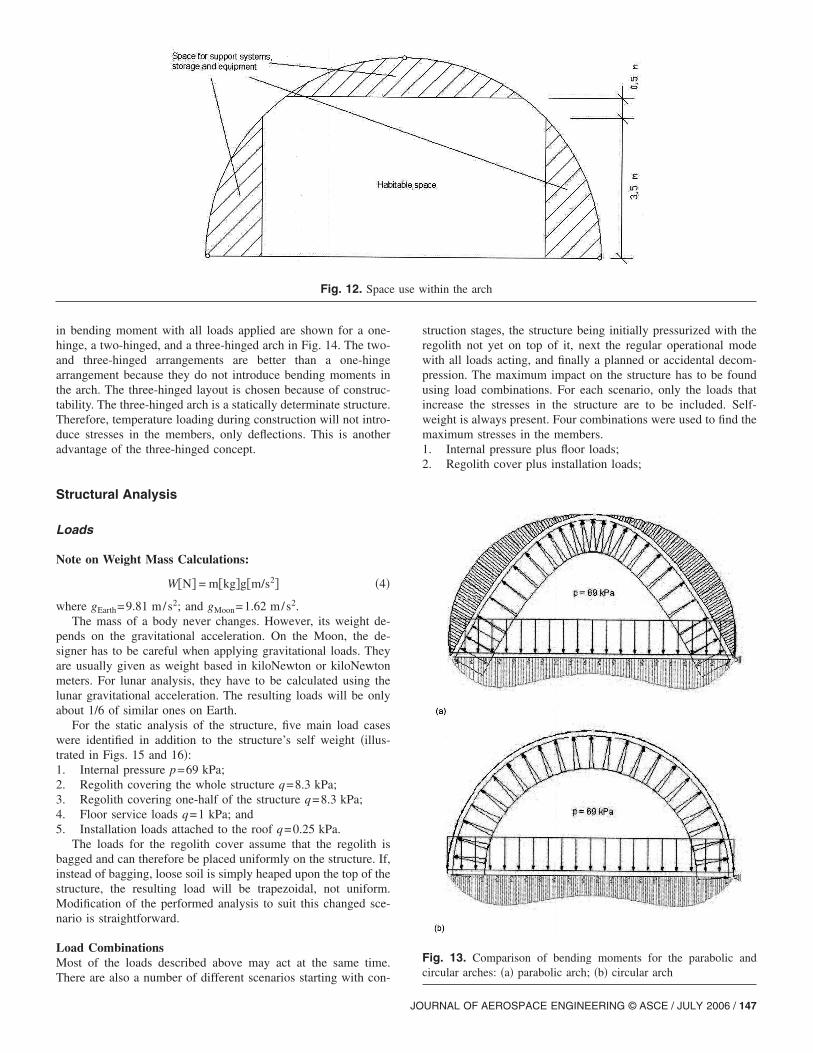
in bending moment with all loads applied are shown for a one-hinge, a two-hinged, and a three-hinged arch in Fig. 14. The two-and three-hinged arrangements are better than a one-hingearrangement because they do not introduce bending moments inthe arch. The three-hinged layout is chosen because of construc-tability. The three-hinged arch is a statically determinate structure.Therefore, temperature loading during construction will not intro-duce stresses in the members, only deflections. This is anotheradvantage of the three-hinged concept.
Structural Analysis
Loads
Note on Weight Mass Calculations:
W�N� = m�kg�g�m/s2� �4�
where gEarth=9.81 m/s2; and gMoon=1.62 m/s2.The mass of a body never changes. However, its weight de-
pends on the gravitational acceleration. On the Moon, the de-signer has to be careful when applying gravitational loads. Theyare usually given as weight based in kiloNewton or kiloNewtonmeters. For lunar analysis, they have to be calculated using thelunar gravitational acceleration. The resulting loads will be onlyabout 1/6 of similar ones on Earth.
For the static analysis of the structure, five main load caseswere identified in addition to the structure’s self weight �illus-trated in Figs. 15 and 16�:1. Internal pressure p=69 kPa;2. Regolith covering the whole structure q=8.3 kPa;3. Regolith covering one-half of the structure q=8.3 kPa;4. Floor service loads q=1 kPa; and5. Installation loads attached to the roof q=0.25 kPa.
The loads for the regolith cover assume that the regolith isbagged and can therefore be placed uniformly on the structure. If,instead of bagging, loose soil is simply heaped upon the top of thestructure, the resulting load will be trapezoidal, not uniform.Modification of the performed analysis to suit this changed sce-nario is straightforward.
Load CombinationsMost of the loads described above may act at the same time.
Fig. 12. Space
There are also a number of different scenarios starting with con-
JO
struction stages, the structure being initially pressurized with theregolith not yet on top of it, next the regular operational modewith all loads acting, and finally a planned or accidental decom-pression. The maximum impact on the structure has to be foundusing load combinations. For each scenario, only the loads thatincrease the stresses in the structure are to be included. Self-weight is always present. Four combinations were used to find themaximum stresses in the members.1. Internal pressure plus floor loads;2. Regolith cover plus installation loads;
ithin the arch
Fig. 13. Comparison of bending moments for the parabolic andcircular arches: �a� parabolic arch; �b� circular arch
use w
URNAL OF AEROSPACE ENGINEERING © ASCE / JULY 2006 / 147

3. All loads; and4. One-half of the regolith cover �during construction�.The RSTAB software was used to determine the governing inter-nal forces, deflections, and cross-section utilization. The two-dimensional analysis includes several simplifications. Forexample, only 0.25 m of the cross section was modeled. Conse-quently, the design loads were calculated per 0.25 m.
Main Structure: Three-Hinged ArchTo minimize structural mass, it is crucial to optimize the crosssection. An infinite number of cross-section types are possible.
Fig. 14. Bending moments for a one- two- and three-hinged arch: �a�one-hinged arch; �b� two-hinged arch; and �c� three-hinged arch
Four different types were examined in this study �see Fig. 17�.
148 / JOURNAL OF AEROSPACE ENGINEERING © ASCE / JULY 2006
Determining the stresses in the structural members for the dif-ferent load combinations can be done by applying the linear su-perposition rule. Load combination one was found to give thehighest stresses for the tie, and load combination three gives themaximum stresses for the arch segments. The regular operationmode will be with all loads acting, so the deflections have to becalculated for load combination three.
The construction material was assumed to be high strengthaluminum, the members being prefabricated on Earth and trans-ported to the Moon. Composite materials that could further savemass are not used mainly because of the lack of experience andcalculation techniques for those materials. So, all calculations arebased on a high strength aluminum alloy with a yield strength of500 N/mm2. The depth of the legs on cross-sections 2 to 4 waslimited to a maximum of 15 cm for the arch segments in order tolimit transportation volume.
The design of the end walls will be discussed in a subsequentsubsection. However, one of the results is already needed at thispoint. Internal air pressure on the end walls introduces tensileforces into the arch structure perpendicular to the already calcu-lated forces. These need to be taken into account when designingthe arch and tie members. The values needed are 130 kN/m forthe arch segments, and 170 kN/m for the tie, respectively. Thesandwich type is the most efficient cross section and is used forboth arch and tie.
The arch member design is relatively easy. It is a structuregoverned by the interaction of bending moment and tension force.
Fig. 15. Static Load Cases 1 and 2: �a� Load Case 1 internalpressure; �b� Load Case 2 regolith cover
The design of the tie/foundation member is more complicated. It

is governed by bending moment. The bending moment dependson the ratio of foundation versus soil stiffness. A stiffness increasein the foundation yields a higher bending moment, since stiffnessattracts forces. So designing the foundation plate is an iterativeprocess. To find out the influence of a difference in the factor ofsafety on the design, it is done and compared for two differentglobal safety factors: safety factor one�4.0, and safety factortwo�5.0. The range for the factor of safety on Earth is, e.g., in
Fig. 16. Static Load Cases 3 and 5: �a� Load Case 3—partial regolithcover; �b� Load Case 4 floor loads; �c� Load Case 5 installation loads
the German design code �DIN�, approximately between 1.7 and
JO
3.5. All of the problems and uncertainties on the Moon will cer-tainly require higher safety factors, so factors of safety of 4.0 orhigher seem reasonable.
Finite element method calculation results for the final iterationcan be looked up in Ruess �2004�. The ASD �American SteelDesign� Module, a part of the RSTAB software, was used tooptimize the members �Dlubal 2004a�. It includes cross-sectionclassification to avoid local buckling, stress analysis for axial,bending, and shear stress and analysis of the allowable stresses.This is a program based on terrestrial design codes, so a fewmodifications were necessary. Modification of the material yieldstresses allowed for implementation of the desired global safetyfactor. For example, implementing a safety factor of 5.0 for thearch requires the following calculation for the input value for theyield strength of aluminum in the program �Eq. �5��:
�5
3��50 kN/cm2
5−
130 kN/m
60 cm2/m� = 13 kN/cm2 �5�
where 5/3=programs material safety factor; 50 kN/cm2=actualaluminum yield strength; 5=chosen design safety factor;130 kN/m=tension force introduced by the end wall loads;60 cm2/m=assumed cross-section area in the direction of the walltension forces; and 13 kN/cm2=ASD input value for the alumi-num yield strength.
Two main conclusions result from the structural analysis. First,the arch segments can have a uniform cross section. It is possible,but not necessary, to adjust the arch cross section to the distribu-tion of internal forces since these are almost uniform. Second, inorder to get an efficient cross section for the tie, it has to beadjusted to the distribution of internal forces. The bending mo-ment has the shape of a parabola, so it was decided to give the tiea similar shape. The section height is affine to the square root ofM. That means that the depth of the tie cross section varies, withthe smallest depth at the ends and the largest in the middle. Fig.18 shows the principal shape of the tie/floor/foundation.
Deflections under all loads, with the structural members de-signed using a safety factor of five, can be viewed in Fig. 19.
The allowable limit for typical terrestrial buildings is usuallytaken to be L /200, L being the span of the structure. The limitwould be 10 m/200=50 mm. If the members are designed usinga global safety factor of 4.0, the cross sections become lighter andthis results in slightly higher deflections, Max u=68 mm. How-ever, it is questionable if the deflection criterion should governthe design, especially when the expected deflections only slightlyexceed it.
Reducing deflections can be done in many different ways.• Strengthen the members. This approach results in extra mass
that is not needed from a strength point of view. Since lowmass is crucial for an economic design, this is not a desirableapproach.
• Strengthen the soil. Sintering the regolith before erecting thestructure will result in a higher modulus of subgrade reaction,and therefore lower deflections of the tie. It does not affect thearch deflections. Calculations show that the modulus of sub-grade reaction would have to be increased about tenfold to getin the range of desired deflections. This is very likely notpossible to be achieved by sintering the regolith. More re-search data is needed for this topic.
• Cambering. All of the loads can be assumed permanent. There-fore, cambering of the members is a solution. The memberscan simply be manufactured in a shape opposite to the calcu-
lated deflections. Manufacturing has to be done very carefullyURNAL OF AEROSPACE ENGINEERING © ASCE / JULY 2006 / 149

and exactly to enable construction onsite. A comparison ofhabitat masses for different safety factors will be given afterthe end walls have been designed.
End WallsThe end walls are also designed to be of the sandwich-type cross-section. This cross section type is simply the most efficient.
The most efficient shape would be a quarter sphere. Bendingmoments for this layout are reduced to a minimum. However, forvarious reasons, such as low transportation volume, easy imple-mentation of air locks, and expandability of the complex, a simpleplate layout is chosen.
The design for these plate structures has to take into accountbending moments in both directions. The finite-element softwareRFEM was used to calculate these internal forces �Dlubal 2004b�.Linear hinged supports are chosen along the perimeter of the plateto represent the connection of the end wall to the arch. The con-nection design has to be done carefully to ensure that this assump-tion is correct.
The only load acting on the end walls is the internal air pres-sure. Loading and support conditions can be seen in Fig. 20.
The structural design is done according to Eq. �6�
Fig. 17. Cross-Section 1 is a simple plate and in Cross-Section 2, thsimilar to a corrugated plate and Cross-Section 4 is essentially a san
Fig. 18. Front view of the general tie shape
150 / JOURNAL OF AEROSPACE ENGINEERING © ASCE / JULY 2006
mx/wx + my/wy �r/SF �6�
where mx=90 kN/m; my =150 kN/m; �r=50 kN/cm2; andSF=safety factor.
Assuming the same cross section in both directions, a safetyfactor of 4.0 results in a minimum section modulus of1920 cm3/m, and a safety factor of 5.0 requires a minimum sec-tion modulus of 2400 cm3/m. Possible cross sections are shownin Figs. 21 and 22. This results in the following masses for theend walls:• 2600 kg for a safety factor of 4.0; and
e is stiffened with a leg perpendicular to it. Cross-Section 3 is veryconstruction.
Fig. 19. Total deflections with the structural members designed forusing safety factor of 5.0. The deflections are magnified by a factor of10 for better illustration.
e platdwich
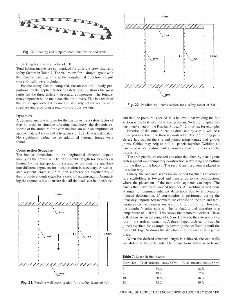
• 3400 kg for a safety factor of 5.0.Total habitat masses are summarized for different crew sizes andsafety factors in Table 7. The values are for a simple layout withthe structure running only in the longitudinal direction, so justtwo end walls were included.
For the safety factors compared, the masses are directly pro-portional to the applied factor of safety. Fig. 23 shows the massratios for the three different structural components: The founda-tion component is the main contributor to mass. This is a result ofthe design approach that focused on statically optimizing the archstructure and providing a ready-to-use floor system.
DynamicsA dynamic analysis is done for the design using a safety factor offive. In order to simulate vibrating machinery, the dynamic re-sponse of the structure for a cam mechanism with an amplitude ofapproximately 4.6 cm and a frequency of 172 Hz was calculated.No significant deflections or additional internal forces werefound.
Construction SequenceThe habitat dimensions in the longitudinal direction dependmainly on the crew size. The transportable length for members islimited by the transportation system, so dividing the membersinto different segments for transportation is necessary. A reason-able segment length is 2.5 m. Ten segments put together wouldthen provide enough space for a crew of six astronauts. Connect-ing the segments has to ensure that all the loads can be transferred
Fig. 20. Loading and support conditions for the end walls
Fig. 21. Possible wall cross-section for a safety factor of 4.0
JO
and that the pressure is sealed. It is believed that welding the fullsection is the best solution to this problem. Welding in space hasbeen performed on the Russian Soyuz T 12 mission, for example.
Erection of the structure can be done step by step. It will be alinear process. First, the floor is constructed. The 2.5 m long pan-els are laid out on the site and joined using tongue and groovejoints. Cables may help to pull all panels together. Welding allpanels provides sealing and guarantees that all forces can betransferred.
The arch panels are erected one after the other, by placing onearch segment on a temporary construction scaffolding and boltingit to the floor at the bottom. The second arch segment is placed inthe same way.
Finally, the two arch segments are bolted together. The tempo-rary scaffolding is lowered and transferred to the next section,where the placement of the next arch segments can begin. Thepanels then have to be welded together. All welding is best doneat night to minimize inherent deflections due to temperature-induced deformation. If construction is performed during thelunar day, unprotected members are exposed to the sun and tem-peratures on the member surface climb up to 150°C. However,the member’s other side will be in shadow and therefore at atemperature of −100°C. This causes the member to deflect. Thesedeflections are in the range of 0.5 m. However, they do not play arole in the arch construction. A three-hinged arch can always bejoined together, for example by lowering the scaffolding until thepieces fit. Fig. 24 shows the structure after the one arch is put inplace.
When the desired structure length is achieved, the end wallsare slid in at the arch ends. The connections between arch and
Table 7. Lunar Habitat Masses
Crew size Total structural mass, SF=4 Total structural mass, SF=5
6 38.6t 48.3t
8 49.7t 62.2t
10 60.8t 76.0t
12 72.0t 89.9t
Fig. 22. Possible wall cross-section for a safety factor of 5.0
URNAL OF AEROSPACE ENGINEERING © ASCE / JULY 2006 / 151

walls have to be established next. The structure is then sealedwith membrane fabric strips glued to the structure along the struc-tural connections where necessary. After completing all necessaryseals, the habitat can be initially pressurized and finally the re-golith cover is put into place.
The floor segments have a mass of 2 ,945 kg, so they weighapproximately 5 kN; where the arch segments have a mass of605 kg, and weigh about 1 kN each.
Certainly, there will be equipment needed to move the partsfrom their landing site to the construction site and into placethere, but no heavy equipment is needed to move 5 kN. A lightcrane is a good solution to put the segments in place onsite.
A solid rendering of a habitat module for a crew of three isillustrated in Fig. 25. The lines on the surface are to enhancecurvature and three-dimensional appearance.
Habitat LayoutThe question of lunar base layouts is a very complex one anddeeply routed in architectural and operations considerations.However, providing different modules for research, habitation,manufacturing, storage, etc., seems like a reasonable approach.These modules can be arranged in a multitude of scenarios. Thefive basic configurations are �Reynolds 1988�:1. Linear: The linear configuration is the simplest of all con-
figurations. It is the repetition of modules with one primarycirculation path. The internal distances from one end to theother are maximized. The spatial characteristics are primarilypublic-type spaces that are noisy and conductive to spacesharing with the circulation path. One of the main problemswith the linear system is safety.
2. Courtyard: When a linear configuration closes on itself, itsbasic characteristics change: The area coverage becomesgreater and the enclosure minimizes. The courtyard is aunique identifiable space. There still exists one primary cir-culation path; however, it now forms a closed loop. An ad-ditional attribute is the courtyard area itself.
Fig. 23. Mass ratios for the three structural components
Fig. 24. Erection of the main structure: 1–floor; 2–scaffolding; and3–arch segment
152 / JOURNAL OF AEROSPACE ENGINEERING © ASCE / JULY 2006
3. Radial: The radial configuration is a centralized space withlinear extensions in more than two directions. The centralarea provides a major functional space with secondary areasradiating. These secondary spaces can be private quiet areasor main circulation routes to additional functional zones. Oneadvantage is the easy access to the central zone.
4. Branching: A linear growth system that expands with second-ary paths from the main linear one characterizes a branchingconfiguration.
5. Cluster: Cluster configurations have no dominant circulationpatterns. Generally, a large area is created.
The proposed habitat modules favor linear expansion overbranching. Therefore, linear and radial layouts are more suitedthan courtyard, branching, or cluster layouts. A radial arrange-ment is most promising with respect to emergency egress, acces-sibility of facilities and the lunar surface, as well as for includingan easily accessible safe haven to protect from solar flares �Rey-nolds 1988�. The central functional zone can be designed in dif-ferent ways. Renderings of a radial lunar habitat configurationwith different possible central zone layouts are shown in Fig. 26.
Details
It is assumed that all parts described above the arch segments, thefloor members, and the end walls can be transported to the Moonin one piece. However, it is also possible to further divide theminto smaller parts if necessary, e.g., dividing the end walls or thefloor segments into two parts. The connections for this scenarioare not designed here, but it is generally possible and should notimpose great problems. A general solution is welding them backtogether on the Moon. Therefore, the only connections actuallydesigned here are the hinged connections in the arch structure aswell as the connection of the end wall to the arch, which is alsoidealized to be a hinged connection.
Connections• The arch connections: Variant 1. The best way to create a
hinge is a bolted connection. Bolted connections are also easyand fast to construct, even for astronauts in EVA suits. Thecross-section’s “webs” can be easily strengthened locally andthen used to make the connection. It is also possible to allowfor tolerances, e.g., by making the holes larger than the bolts’diameter. This way manufacturing inaccuracies and memberdeformations during construction; for example, due to nonlin-ear temperature loads, can be included in the design. However,
Fig. 25. Rendering of a lunar habitat module
it is not necessary to include large tolerances in this design.

The connection design process and connection dimensionshave been performed, and Figs. 27 and 28 show detailed draw-ings of the hinged connections.
• The arch connections: Variant 2. Although the sealing proce-dure for variant one is relatively easy, it is inconvenient andlabor intensive. If it were possible to design the hinges to beairtight, the structure would be cheaper and likely faster toerect. The result of these thoughts can be seen in Figs. 29 and30, and were conceived by the second writer this paper.The tension bar area is determined in Eq. �7�:
A = SF*N/fy = 4.3 cm2 �7�
where A=required tension bar area; SF=safety factor=5.0,N=design tension force=43 kN; and fy=material yieldstrength =50 kN/cm2.
The strengthened plate is designed like a simple beam �seeFig. 31�. This approach is more conservative than designing it likea plate. The plate has to satisfy the following two conditions �Eqs.
Fig. 26. Different solutions for a radial arrangement
8 and 9�,
JO
M
W=
fy
SF�8�
where M=design moment; W=elastic section modulus=bh2 /6;fy=material yield strength=50 kN/cm2; and SF=safetyfactor =5.0.
V
A=
fy
�3 · SF�9�
where V=design shear, A=area in shear; fy=material yieldstrength=50 kN/cm2; and SF=safety factor =5.0.
Bending governs the design and yields a plate thickness oft=11.4 mm. A thickness of t=12 mm will be used.
End Wall ConnectionsThe shape of the arch construction right before the end walls areput into place will determine the end wall shape. This is to ensurethat the wall fits in place. The wall panel rests on the floor, butthere will be a gap between the wall and the arch segments be-cause of construction tolerances. Aluminum plates extend fromthe wall, and have to be welded to the floor and arch, respectively.These plates can only be welded at the end, so using fillet weldswith the same material strength as the aluminum for the members,the weld size is governing the plate thickness, too. Welding has
Fig. 27. Connection of the arch segments
Fig. 28. Connection of the arch segments to the floor
URNAL OF AEROSPACE ENGINEERING © ASCE / JULY 2006 / 153

the advantage of also sealing the connection, but additional mem-brane fabric strips can be applied if desired. The weld sizes arecalculated in Eqs. �10� and �11�:
130 kN/m
a
50 kN/cm2
5.0Þ a 0.13 cm �10�
where 130 kN/m=wall support reaction on the arch �tension�;a=fillet weld size �throat�; 50 kN/cm2=weld material yieldstrength; and 5.0=applied global safety factory.
170 kN/m
a
50 kN/cm2
5.0Þ a 0.17 cm �11�
where the wall support reaction is now 170 kN/m.According to DIN 18800, the weld size is also limited to
a 0.7tmin �12�
where tmin�smallest plate thickness. For both the arch and floor,this requirement is met. To make construction simpler, full filletwelds will be used. This results in a=1.4 mm for the wall con-nections using two welds. The floor weld will very likely be gov-
Fig. 29. Alternative connection of the arch seg
Fig. 30. Alternative connection of arch segments to the floor�concept by Schänzlin�
154 / JOURNAL OF AEROSPACE ENGINEERING © ASCE / JULY 2006
erned by onsite manufacturing accuracy, and can be thicker ifnecessary.
Additional bracing is not necessary, but for a conservative de-sign it could be a good idea to make sure the wall support reac-tions �tension� are transferred to the full cross section of both archand floor—by including an inclined plate in between the webswhere the weld is made. Detailed drawings of the connectionswithout additional bracing are shown in Figs. 32 and 33.
Pressure SealingThe nature of the structural system makes it necessary to seal theopenings in the structure with a separate application. The areaaround the three hinges has to be sealed air tight with a system
�concept by Schaenzlin, University Stuttgart�
Fig. 31. Statics for a simple beam under a concentrated load
ments
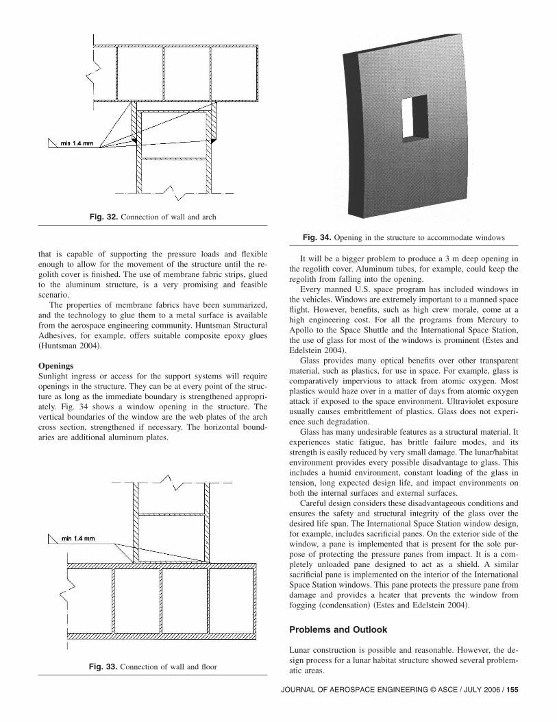
that is capable of supporting the pressure loads and flexibleenough to allow for the movement of the structure until the re-golith cover is finished. The use of membrane fabric strips, gluedto the aluminum structure, is a very promising and feasiblescenario.
The properties of membrane fabrics have been summarized,and the technology to glue them to a metal surface is availablefrom the aerospace engineering community. Huntsman StructuralAdhesives, for example, offers suitable composite epoxy glues�Huntsman 2004�.
OpeningsSunlight ingress or access for the support systems will requireopenings in the structure. They can be at every point of the struc-ture as long as the immediate boundary is strengthened appropri-ately. Fig. 34 shows a window opening in the structure. Thevertical boundaries of the window are the web plates of the archcross section, strengthened if necessary. The horizontal bound-aries are additional aluminum plates.
Fig. 32. Connection of wall and arch
Fig. 33. Connection of wall and floor
JO
It will be a bigger problem to produce a 3 m deep opening inthe regolith cover. Aluminum tubes, for example, could keep theregolith from falling into the opening.
Every manned U.S. space program has included windows inthe vehicles. Windows are extremely important to a manned spaceflight. However, benefits, such as high crew morale, come at ahigh engineering cost. For all the programs from Mercury toApollo to the Space Shuttle and the International Space Station,the use of glass for most of the windows is prominent �Estes andEdelstein 2004�.
Glass provides many optical benefits over other transparentmaterial, such as plastics, for use in space. For example, glass iscomparatively impervious to attack from atomic oxygen. Mostplastics would haze over in a matter of days from atomic oxygenattack if exposed to the space environment. Ultraviolet exposureusually causes embrittlement of plastics. Glass does not experi-ence such degradation.
Glass has many undesirable features as a structural material. Itexperiences static fatigue, has brittle failure modes, and itsstrength is easily reduced by very small damage. The lunar/habitatenvironment provides every possible disadvantage to glass. Thisincludes a humid environment, constant loading of the glass intension, long expected design life, and impact environments onboth the internal surfaces and external surfaces.
Careful design considers these disadvantageous conditions andensures the safety and structural integrity of the glass over thedesired life span. The International Space Station window design,for example, includes sacrificial panes. On the exterior side of thewindow, a pane is implemented that is present for the sole pur-pose of protecting the pressure panes from impact. It is a com-pletely unloaded pane designed to act as a shield. A similarsacrificial pane is implemented on the interior of the InternationalSpace Station windows. This pane protects the pressure pane fromdamage and provides a heater that prevents the window fromfogging �condensation� �Estes and Edelstein 2004�.
Problems and Outlook
Lunar construction is possible and reasonable. However, the de-sign process for a lunar habitat structure showed several problem-
Fig. 34. Opening in the structure to accommodate windows
atic areas.
URNAL OF AEROSPACE ENGINEERING © ASCE / JULY 2006 / 155

1. Providing a floor system that is ready to use resulted in highbending moments and therefore high mass for the examinedapproach. The high interdependency of floor stiffness andbending moments is a result of the soil model that was used.If it is possible to reduce the floor stiffness below a certainlevel and still make the cross section capable of resisting theinternal forces, the floor could be designed to be significantlylighter. This is because of a change in the general shape ofthe floor bending moment once the ratio of floor stiffness tosoil stiffness is below a certain level. Maximum bending mo-ments are greatly reduced �compare Figs. 35 and 14�.
With the employed aluminum alloy and safety factors,this scenario is not working. However, advances in ultrahighstrength materials—e.g., carbon nanotubes, and continuedlunar research and exploration that enable the use of lowersafety factors—might benefit the floor design in the future.If, for example, a safety factor of only 2.0 could be used withthe same aluminum material, the mass of the floor memberswould be reduced to about 25% of the floor member massused for a safety factor of 4.0.
2. Extreme temperature may be a problem during the erectionof the structure. The chosen sandwich-type cross section isvery efficient for the operational loads but not for the tem-perature differentials between top and bottom plates whileexposed to the Sun. But although the members deform, erec-tion is no problem because of the three-hinged static system.An additional insulation layer is proposed for statically inde-terminate structures to protect the structure from the Sun-induced temperature variations. There is much room forfurther research on the temperature gradient problems on thelunar surface.
3. With every advance in science related to lunar construction,different concepts will have to be re-evaluated. Evaluationcriteria have to be weighted eventually.
4. A lunar transportation system does not exist. So all dimen-sions are based on assumptions on what is “transportable.”When the transportation vehicle for this purpose is devel-oped, and dimension restrictions are available, structuralmembers might be subject to dimension changes.
5. In addition, one has to be aware of the wide range of assump-tions and unknowns that cannot be checked now. Many ofthese assumptions will be verified in the near future duringthe space agencies’ lunar programs. Most important will bedata on regolith properties, meteoroid activity, and radiation.
The most important point to make is that there are significant
Fig. 35. Altered general floor bending moment distribution
difficulties with our return to the Moon with permanent outposts.
156 / JOURNAL OF AEROSPACE ENGINEERING © ASCE / JULY 2006
Our study was primarily focused on a possible structural design,recognizing that the design must be coupled with many othertechnical and nontechnical aspects of creating a civilization on theMoon.
References
Benaroya, H. �1994�. “Reliability of structures for the Moon.” Struct.Safety, 15, 67–84.
Benaroya, H. �1998�. “Economic and technical issues for lunar develop-ment.” J. Aerosp. Eng., 11�4�, 111–118.
Benaroya, H. �2002� “An overview of lunar base structures: Past andfuture.” AIAA Space Architecture Symposium, AIAA, Reston, Va.,1–12.
Benaroya, H., Bernold, L., and Chua, K. M. �2002�. “Engineering, de-sign, and construction of lunar bases.” J. Aerosp. Eng., 15�2�, 33–45.
Benaroya, H., and Ettouney, M. �1992a�. “Framework for evaluation oflunar base concepts.” J. Aerosp. Eng., 5�2�, 187–198.
Benaroya, H., and Ettouney, M. �1992b�. “Design and construction con-siderations for a lunar outpost.” J. Aerosp. Eng., 5�3�, 261–273.
Braun, B. �2003�. “Faserverbundkunststoffe �FVK� als tragende Struk-tur.” Tech. Rep., Univ. of Stuttgart, Institute of Structural Design�KE�.
Broad, W. J. �1989�. “Lab offers to develop an inflatable space base.”New York Times, November 14, Sec. C pp. 5.
Buchhold, H. A. �1985�. An introduction to cable roof structures, Cam-bridge University Press, Cambridge University, Mass.
Burgoyne, C. J. �1999�. “Advanced composites in civil engineering inEurope.” Struct. Eng. Int. (IABSE, Zurich, Switzerland), 4.
Chang, K. �2004�. “New Moon: Planning the return to space.” New YorkTimes, Vol. 20, F1–F4.
Chow, P. Y., and Lin, T. Y. �1989�. “Structural engineers concept of lunarstructures.” J. Aerosp. Eng., 2�1�, 1–9.
Chua, K. M., Yuan, Z., and Johnson, S. W. �1990�. “Foundation design ofa large diameter radio telescope on the Moon.” SPACE 90, ASCE,Reston, Va., 707–716.
Cohen, M. M. �2002�. “Selected precepts in lunar architecture.” Tech.Rep., 53rd Int. Astronautical Congress, The World Space Congress,Houston.
Criswell, M. E., Sadeh, W. Z., and Abarbanel, J. E. �1996�. “Design andperformance criteria for inflatable structures in space.” SPACE 96,ASCE, Reston, Va., 1045–1051.
Daga, A. W., Daga, M. A., and Wendel, W. R. �1992�. “Evolving con-cepts of lunar architecture: The potential of subselene development.”2nd Conf. on Lunar Bases and Space Activities of the 21st Century,W. W. Mendell, ed., 281–291. NASA Conf. Publ. No. 3166, NASA,Washington, D.C.
Dlubal. �2004a�. “RStab 5.0 finite-element software, Dlubal GmbH, Tief-enbach, Germany. �http://www.dlubal.de.
Dlubal. �2004b�. “RFEM 1.xx finite-element software, Dlubal GmbH,Tiefenbach, Germany. �http://www.dlubal.de.
Dubbink, T. �2001�. “Ideas for Martian bases in the 20th century.” Tech.Rep., Delft Univ. of Technology, Delft, The Netherlands.
Duke, M. B., and Benaroya, H. �1993�. “Applied mechanics of lunarexploration and development.” Appl. Mech. Rev., 46�6�, 272–277.
Eckhart, P. �1999�. The lunar base handbook, McGraw-Hill, New York.Eichold, A. �2000�. “Conceptual design of a crater lunar base.” Proc.,
Return to the Moon II, AIAA, Reston, Va., 126–136.Elrod, M. �1995�. “Considerations of a habitat design.” J. Br. Interplanet.
Soc., 48, 39–42.Estes, L. R., and Edelstein, K. S. �2004�. “Engineering of windows for
the international space station.” Space 04, ASCE, Reston, Va.,580–584.
Ettouney, M., and Benaroya, H. �1992�. “Regolith mechanics, dynamics,and foundations.” J. Aerosp. Eng., 5�2�, 214–229.
Ettouney, M., Benaroya, H., and Agassi, N. �1992�. “Cable structures and

lunar environment.” J. Aerosp. Eng., 5�3�, 297–310.Graf, J. C. �1988�. “Construction operations for an early lunar base.”
SPACE 88, ASCE, Reston, Va., 190–201.Happel, J. A. �1992�. “The design of lunar structures using indigenous
construction materials.” MS in Civil Engineering, thesis, Univ. ofColorado, Colo.
Happel, J. A. �1993�. “Indigenous materials for lunar construction.” Appl.Mech. Rev., 46�6�, 313–325.
Happel, J. A., Willam, K., and Shing, B. �1992�. “Prototype lunar baseconstruction using indigenous materials.” SPACE 92, ASCE, Reston,Va., 112–122.
Hijazi, Y. �1988�. “Prefabricated foldable lunar base modular systems forhabitats, offices, and laboratories,” NASA Conf. Publ. 3166, NASA,Washington, D.C.
Huntsman Co, USA. �2004�. “Huntsman advanced materials.” Everberg,Belgium. �http://www.huntsman.com.
Johnson, S. W., Chua, K. M., and Carrier, W. D., III. �1995�. “Lunar soilmechanics.” J. Br. Interplanet. Soc., 48�1�, 43–48.
Kennedy, K. J. �2002�. “The vernacular of space architecture.” AIAASpace Architecture Symposium, Reston, Va.
Kennedy, K. J. �1992�. “A horizontal inflatable habitat for SEI.” SPACE92, ASCE, Reston, Va., 135–146.
Kennedy, K. J., and Adams, C. M. �2000�. “ISS TransHab: An lnflatablehabitat.” SPACE 2000, ASCE, Reston, Va., 89–100.
Leonard, W. J. �1988�. Tension structures behavior and analysis,
McGraw-Hill, New York.JO
LIQUIFER. �2002�. �http://www.liquifer.atNowak, P. S., Criswell, M. E., and Sadeh, W. Z. �1990�. “Inflatable struc-
tures for a lunar base.” SPACE 90, ASCE, Reston, Va., 510–519.O’Dale, C. D. �1994�. “Commercial activities resulting from a lunar
base.” J. Br. Interplanet. Soc., 47�12�, 549–554.Otto, F. �1973�. Tensile structures, The MIT Press, Cambridge, Mass.Reynolds, K. H. �1988�. “Preliminary design study of lunar housing con-
figurations.” NASA Conf. Publ. No. 3166, NASA, Washington, D.C.,255–259.
Roberts, M. �1988�. “lnflatable habitation for the lunar base.” NASA Conf.Publ. No. 3166, NASA, Washington, D.C.
Ruess, F. �2004�. “Structural analysis of a lunar base.” Master’s thesis,Univ. at Stuttgart/Rutgers Univ.
Sadeh, W. Z., and Criswell, M. E. �1994�. “A generic inflatable structurefor a lunar/martian base.” SPACE 94, ASCE, Reston, Va., 1146–1156.
Sadeh, W. Z., and Criswell, M. E. �1995�. “Inflatable structures for alunar base.” J. Br. Interplanet. Soc., 48�1�, 33–48.
Schrunk, D. G. �2002�. “The Moon: Optimum location for the firstindustrial/scientific base in space.” SPACE 02, ASCE, Reston, Va.,122–128.
Spudis, P. D. �2003�. “Harvest the Moon.” Astronomy, 6, 42–47.Vanderbilt, M. D., Criswell, M. E., and Sadeh, W. Z. �1988�. “Structures
for a lunar base.” SPACE 88, ASCE, Reston, Va., pp. 352–361.Zippert, H. �2004�. “Zimmer mit erdblick,” GEO Special Der Mond, 6,
90–99.
URNAL OF AEROSPACE ENGINEERING © ASCE / JULY 2006 / 157