structural analysis and design report
TRANSCRIPT
The Office of the Municipal Executive
Ghyanglekh Rural Municipality Bagmati Province, Sindhuli, Nepal
Structural Analysis and Design Report Hospital Main Blocks A&B
Ghyanglekh Rural Municipality, Sindhuli, Nepal
Empirical Engineering Consultancy (P) Limited Sukedhara, Kathmandu Metropolitan City 44600, Bagmati, Nepal
Email: [email protected],T: 01-5908021

Ghiyanglekh Sindhuli 10 beded Hospital
Block A+B
(STRUCTURAL ANALYSIS AND DESIGN REPORT)
SUBMITTED BY:
Dr Govind Prasad Lamichhane
Associate Prof. PU
NEC 5312 A
Empirical Engineering Consultancy Pvt. Ltd. Sukedhara, Kathamndu, Nepal, Email:[email protected], PH:015908021
2021
Table of Contents
1. INTRODUCTION ............................................................................................................. 1
2. SEISMIC VULNERABILITY OF NEPAL....................................................................... 1
3. PHILISOPHY OF SEISMIC DESIGN .............................................................................. 1
4. BUILDING DESCRIPTION ............................................................................................. 3
5. STRUCTURAL SYSTEM................................................................................................. 5
6. LOADS ADOPTED........................................................................................................... 5
7. SEISMIC DESIGN PARAMETERS ................................................................................. 7
8. PRELIMINARY DESIGN................................................................................................. 8
9. FINITE ELEMENT MODELING AND ANALYSIS OF BUILDING USING SAP2000
V19 9
9.1 LOADS APPLIED ON BUILDING: ........................................................................ 11
9.1.1 Floor Finish ........................................................................................................ 11
9.1.2 Live Load ........................................................................................................... 13
9.1.3 Wall load ............................................................................................................ 15
9.2 LATERAL LOAD ESTIMATION ACCORDING TO IS 1893:2016 ..................... 16
9.2.1 A block ............................................................................................................... 16
9.2.2 B block .............................................................................................................. 19
9.3 LOAD CASES AND COMBINATION ................................................................... 21
9.3.1 Load Cases ......................................................................................................... 21
9.3.2 Load Combinations ............................................................................................ 21
9.4 Base Reaction ............................................................................................................ 22
9.5 MODAL RESULT .................................................................................................... 22
9.6 DRIFT OF THE BUILDING .................................................................................... 24
9.7 CHECK FOR TORSION .......................................................................................... 25
10. DESIGN OF STRUCTURL MEMBERS ..................................................................... 26
10.1 Design of slab ........................................................................................................ 26
10.2 Design of Beam ..................................................................................................... 26
10.3 Design of Column .................................................................................................. 30
10.4 Design of foundation ............................................................................................. 33
10.5 Design of staircase ................................................................................................. 33
11. CONCLUDING REMARKS ........................................................................................ 34
12. REFERENCE CODE .................................................................................................... 35
Annex 1: Column Detailing ..................................................................................................... 37
Annex 3 Beam Detailing .......................................................................................................... 38
Annex 4: Design of Foundation ............................................................................................... 40
Annex 5: Design of Slab .......................................................................................................... 41

Annex 6: Design of Staircase ................................................................................................... 41
Annex 7: Design of Shear wall with strap beam ...................................................................... 41

1
1. INTRODUCTION
The basic aim of the structural design is to build a structure, which is safe, fulfilling the intended
purpose during its estimated life span, economical in terms of initial and maintenance cost, durable
and also maintaining a good aesthetic appearance.
A building is considered to be structurally sound, if the individual elements and the building as a
whole satisfy the criteria for strength, stability and serviceability and in seismic areas additional
criteria for ductility and energy absorption capabilities. The overall building must be strong enough to
transfer all loads through the structure to the ground without collapsing or losing structural integrity
by rupture of the material at the critical sections, by transformation of the whole or parts into
mechanisms or by instability.
2. SEISMIC VULNERABILITY OF NEPAL
Nepal is located in the boundary of two colliding tectonic plates, namely, the Indian Plate (Indo-
Australian Plate) and the Tibetan Plate (Eurasian Plate). The Indian Plate is constantly moving under
the Tibetan Plate causing many minor and major earthquakes in this region. As a result, Nepal has
witnessed many major as well as minor earthquakes during the past. Records of earthquakes are
available in Nepal since 1255 A.D. Those records show that around 18 major earthquakes have
shaken Nepal since then. The 1833 A.D. earthquake and 1934 A.D Bihar-Nepal earthquakes and
2015 Gorkha earth quake were the most destructive ones in the history of Nepal.
Thus structures to be built in Nepal need to be suitably designed and detailed, so as to counteract the
forces due to earthquakes.
3. PHILISOPHY OF SEISMIC DESIGN
The probability of occurrence of severe earthquakes is much less than that of minor earthquakes at a
given site. Many of the structures may never experience severe earthquakes during its lifetime.
Construction of any ordinary structures to resist such severe earthquakes without undergoing any
damage may not be considered economically feasible, as it may be far cheaper to repair or even
rebuild the structure after having severe and strong shaking. On the other hand, structures located in
seismic areas experience minor earthquakes rather frequently. Thus, in the event of severe and strong
shaking, the structure is allowed to have some damage which may be repairable or even irreparable,
but the structure will not be allowed to collapse completely, thereby ensuring the safety of life and the
property in the structure. In order that one does not have to undertake frequent repair and retrofitting
of the structure, the structure should not have any damage during minor level of shaking. In case of
moderate shaking the structure is allowed to have some non-structural damage without endangering

2
life and property within the structure. During such event the level of damage should be such that it
can be economically repaired.
The structures are generally designed for much lower seismic forces than what it may actually
experience during its life time. Since the structure is expected to undergo damage in the event of a
severe shaking, reliance is placed on the inelastic response of the structure beyond yield. Therefore,
structures have to be ductile and capable of dissipating energy through inelastic actions. Ductility can
be achieved by avoiding brittle modes of failures. Brittle modes of failures include, shear and bond
failure. Thus, structures should be designed on Weak beam-Strong column philosophy.

3
4. BUILDING DESCRIPTION
Type: Hospital building
Building Typology: Reinforcement Concrete Frame Building
Form:
Plan Shape: Irregular shaped
Plan Configuration: Irregular
Vertical Configuration: Irregular
Plinth Area: 658 m2
Number of Stories Two Storey
Position of the Building: Free Standing
Total Height: 11.7 m from plinth level
Inter Storey Height: 3.6 m.
Maximum length of Beam: 4.805 m
Size of Columns: 350 x 350 mm2
Wall Thickness: 230mm
Floor/Roof structure: 150 mm slab floor
Location of site: Ghiyanglekh Sindhuli
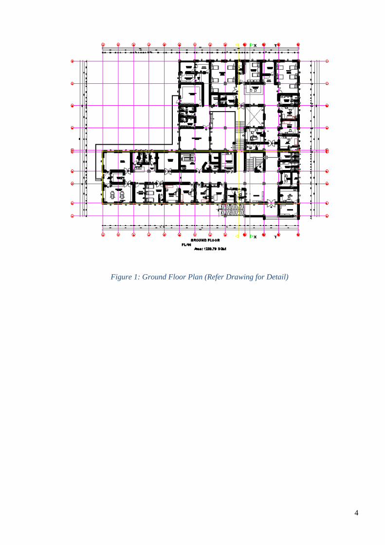
4
Figure 1: Ground Floor Plan (Refer Drawing for Detail)
5
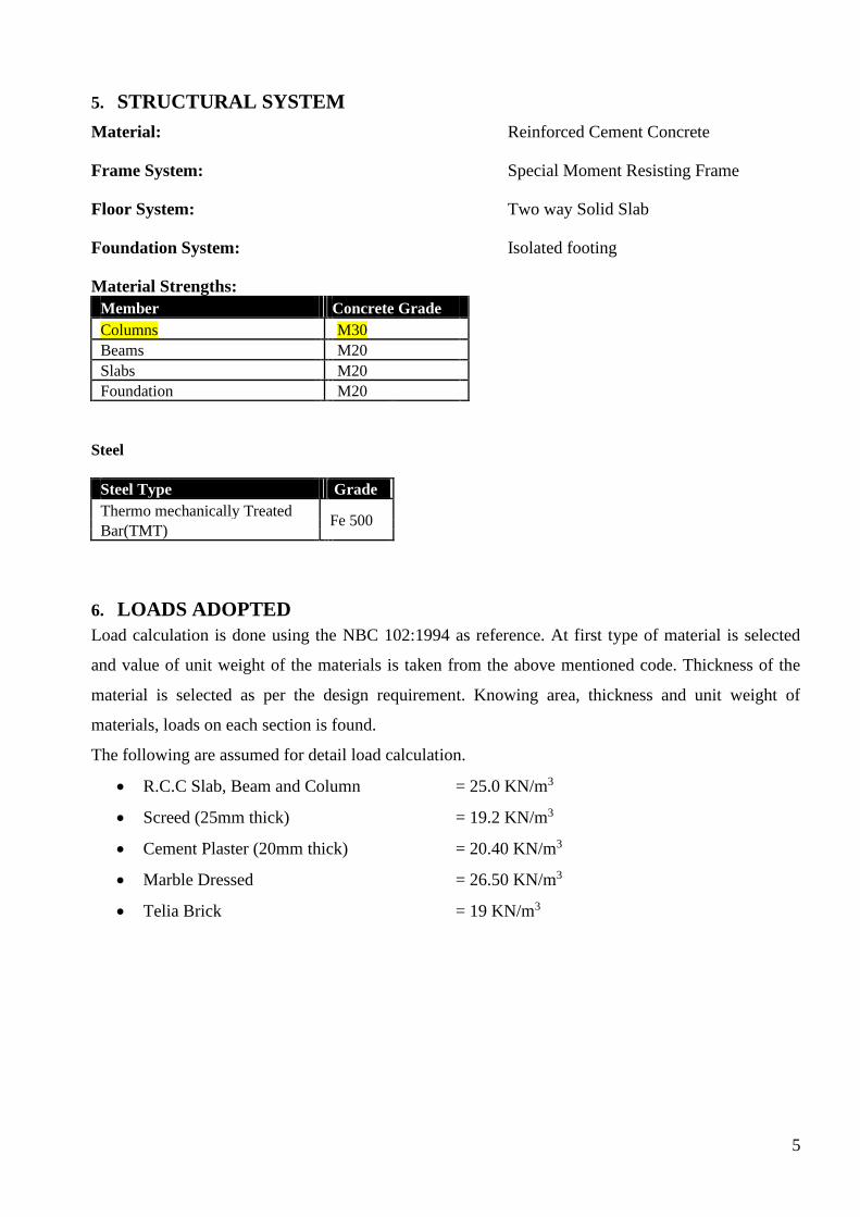
5. STRUCTURAL SYSTEM
Material: Reinforced Cement Concrete
Frame System: Special Moment Resisting Frame
Floor System: Two way Solid Slab
Foundation System: Isolated footing
Material Strengths:
Member
Concrete Grade
Columns M30
Beams M20
Slabs M20
Foundation M20
Steel
Steel Type Grade
Thermo mechanically Treated Fe 500
Bar(TMT)
6. LOADS ADOPTED
Load calculation is done using the NBC 102:1994 as reference. At first type of material is selected
and value of unit weight of the materials is taken from the above mentioned code. Thickness of the
material is selected as per the design requirement. Knowing area, thickness and unit weight of
materials, loads on each section is found.
The following are assumed for detail load calculation.
• R.C.C Slab, Beam and Column = 25.0 KN/m3
• Screed (25mm thick) = 19.2 KN/m3
• Cement Plaster (20mm thick) = 20.40 KN/m3
• Marble Dressed = 26.50 KN/m3
• Telia Brick = 19 KN/m3
6
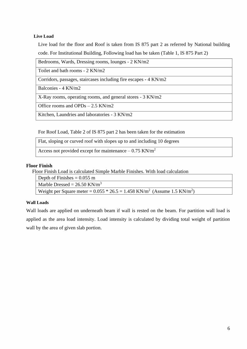
Live Load
Live load for the floor and Roof is taken from IS 875 part 2 as referred by National building
code. For Institutional Building, Following load has be taken (Table 1, IS 875 Part 2)
Bedrooms, Wards, Dressing rooms, lounges - 2 KN/m2
Toilet and bath rooms - 2 KN/m2
Corridors, passages, staircases including fire escapes - 4 KN/m2
Balconies - 4 KN/m2
X-Ray rooms, operating rooms, and general stores - 3 KN/m2
Office rooms and OPDs – 2.5 KN/m2
Kitchen, Laundries and laboratories - 3 KN/m2
For Roof Load, Table 2 of IS 875 part 2 has been taken for the estimation
Flat, sloping or curved roof with slopes up to and including 10 degrees
Access not provided except for maintenance – 0.75 KN/m2
Floor Finish
Floor Finish Load is calculated Simple Marble Finishes. With load calculation
Depth of Finishes = 0.055 m
Marble Dressed = 26.50 KN/m3
Weight per Square meter = 0.055 * 26.5 = 1.458 KN/m2 (Assume 1.5 KN/m2)
Wall Loads
Wall loads are applied on underneath beam if wall is rested on the beam. For partition wall load is
applied as the area load intensity. Load intensity is calculated by dividing total weight of partition
wall by the area of given slab portion.
7
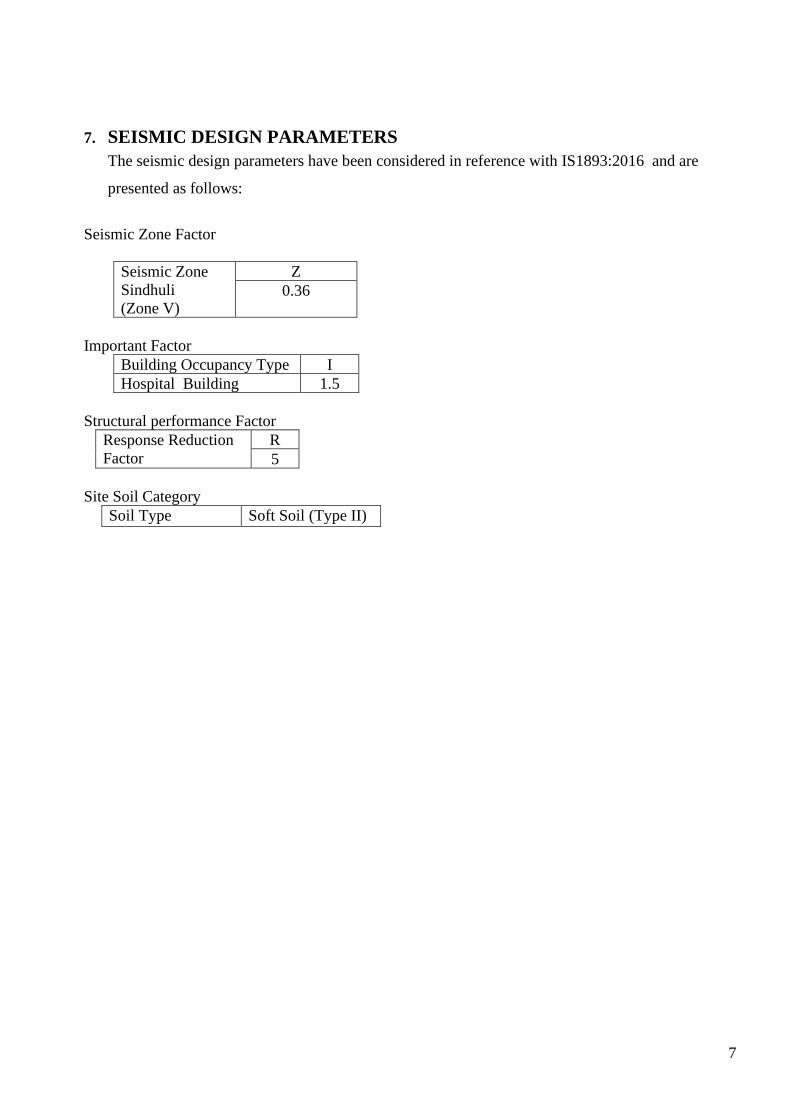
7. SEISMIC DESIGN PARAMETERS
The seismic design parameters have been considered in reference with IS1893:2016 and are
presented as follows:
Seismic Zone Factor
Seismic Zone
Sindhuli
(Zone V)
Z
0.36
Important Factor
Building Occupancy Type I
Hospital Building 1.5
Structural performance Factor
Response Reduction
Factor
R
5
Site Soil Category
Soil Type Soft Soil (Type II)
8
8. PRELIMINARY DESIGN
For the analysis, dead load is also necessary which depends upon the size of member itself. So it is
necessary to pre-assume logical size of member which will neither overestimate the load nor under
estimate the stiffness of the building. So, the tentative sizes of the structural elements are determined
through the preliminary design so that the pre-assumed dimensions may not deviate considerably
after analysis thus making the final design both safe and economical. Tentative sizes of various
elements have been determined as follows:
Slab:
Preliminary design of slab is done as per the deflection criteria as directed by code Clause 23.2.1 of
[IS 456: 2000]. The cover provided is 20 mm and the grade of concrete used in the design is M20.
According to which,
Span ≤ (Mft x Mfc) x Basic Value
Eff. Depth
Where, the critical span is selected which is the maximum shorter span among the all slab element.
This is done to make uniformity in slab thickness. The amount of reinforcement will be varied slab to
slab but the thickness will be adopted corresponding to the entire slab.
Beam:
Preliminary design of the beam is done as per the deflection criteria as directed by code Clause 23.2.1
of [IS 456: 2000] and ductility criteria of ACI code. The cover provided is 30 mm and the grade of
concrete used in the design is M20.
According to which,
Span ≤ (Mft x Mfc) x Basic Value x Correction Factor
Eff. Depth for span x Correction Factor for Flange
But,
According to Ductility code, Spacing of Stirrups in beam should not exceed d/4 or 8 times diameter
of minimum size of bar adopted and should not greater than 100mm. So, for considering construction
difficulties in actual field, it is logical to use d/4 as spacing as per the construction practice in Nepal.
COLUMN:
Preliminary design of column is done from the assessment of approximate factored gravity loads and
live loads coming up to the critical section. To compensate the possible eccentric loading and
earthquake loads the size is increased by about 25% in design. For the load acting in the column, live
load is decreased according to IS 875: 1978. Initially a rectangular column is adopted in this building
project so as to provide internal aesthetics required from architecture point of view but the column
size and shape will vary as per the requirement for the analysis, design and aesthetic value. The cover
provided is 40 mm and the grade of concrete used in the column design is M25.

9
9. FINITE ELEMENT MODELING AND ANALYSIS OF BUILDING USING
SAP2000 V19
The FE model of building is developed in SAP2000 V22, a general purpose FE analysis and design
software. The size of beams and columns as obtained from preliminary analysis are adjusted
according to architectural need. Beam and columns are modeled as frame element. Slabs are also
modeled as shell element.
Beam and column are assumed to be line element having six degree of freedom at each node and slab
is assumed to be shell element having six degree of freedom at each node. Floor diaphragm is used in
the structure to reduce degree of freedom to three for each floor level.
Imposed loads have been modeled as uniform distributed loads. Similarly, wall loads are modeled as
uniformly distributed line loads. The columns and walls were “fixed” at their base.
The 3D model is assumed to be fixed at tie beam level. Suitable assumptions are made and FE model
as shown in Fig 2 is developed.
Figure 2: Finite Elemental Modeling in Sap2000 V 22 (A Block)
Loading due to wall, floor finish and live load is as shown in figure below and analysis is done by
static method (seismic coefficient method) and Response Spectrum Method. Following forces is
observed during Analysis:
10
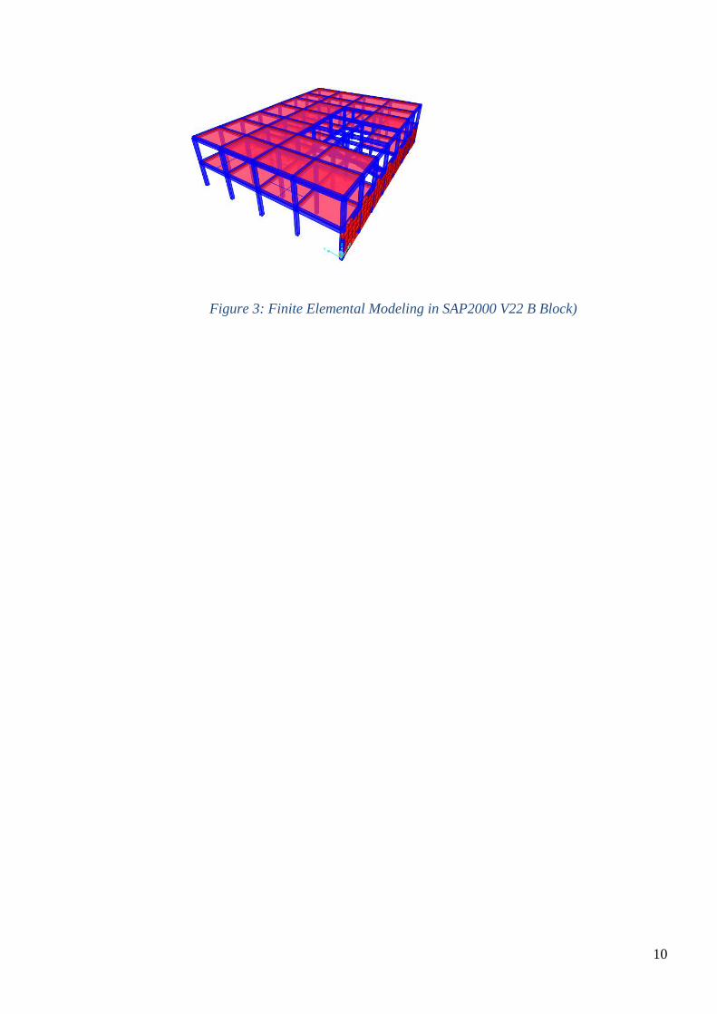
Figure 3: Finite Elemental Modeling in SAP2000 V22 B Block)
11
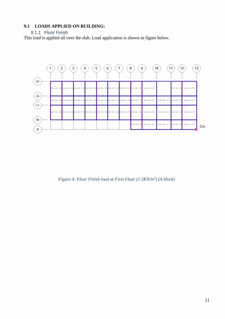
9.1 LOADS APPLIED ON BUILDING:
9.1.1 Floor Finish This load is applied all over the slab. Load application is shown in figure below.
Figure 4: Floor Finish load at First Floor (1.5KN/m2) (A block)

12
Figure 5: Floor Finish load at First Floor (1.5KN/m2) (B block)
13
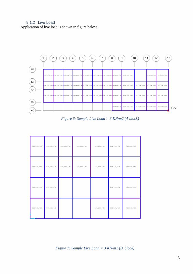
9.1.2 Live Load Application of live load is shown in figure below.
Figure 6: Sample Live Load > 3 KN/m2 (A block)
Figure 7: Sample Live Load < 3 KN/m2 (B block)

14
Please Refer Model Provided along with the Report for Detail
15
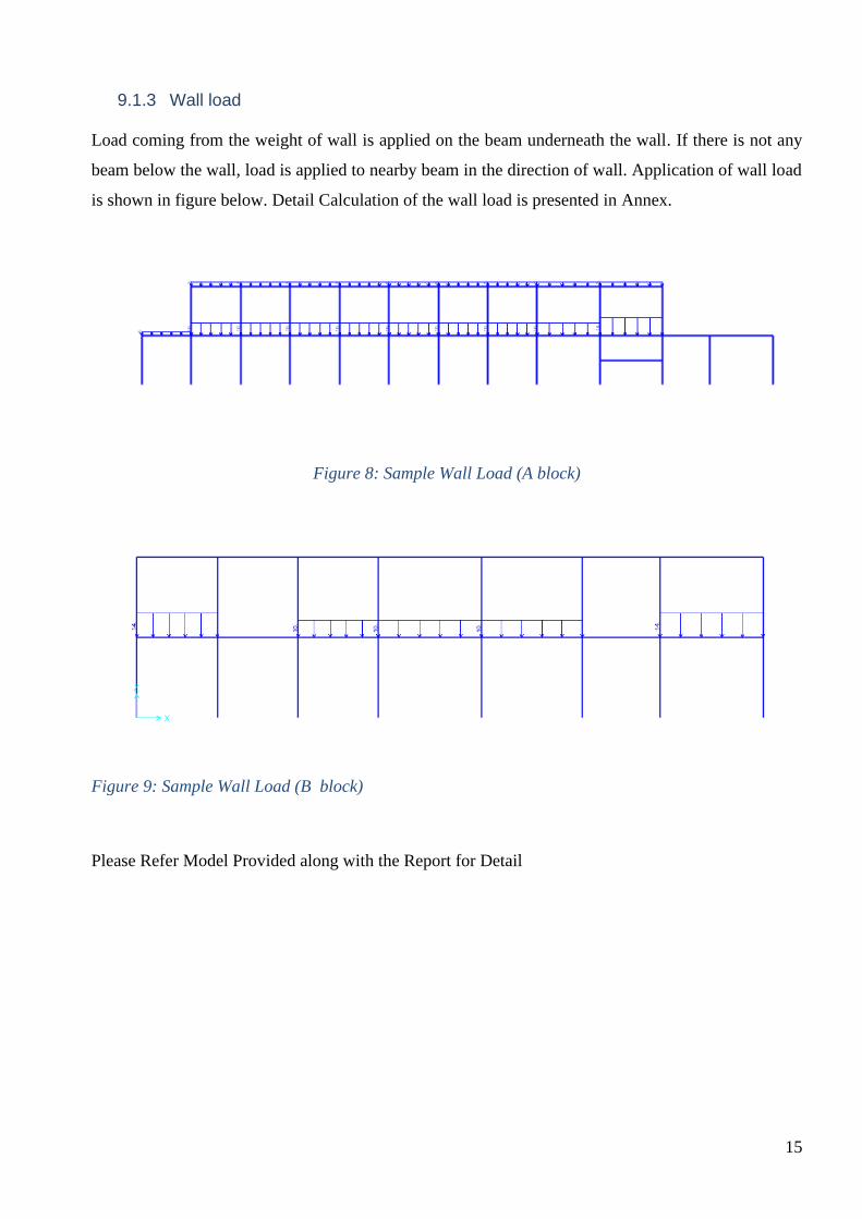
9.1.3 Wall load
Load coming from the weight of wall is applied on the beam underneath the wall. If there is not any
beam below the wall, load is applied to nearby beam in the direction of wall. Application of wall load
is shown in figure below. Detail Calculation of the wall load is presented in Annex.
Figure 8: Sample Wall Load (A block)
Figure 9: Sample Wall Load (B block)
Please Refer Model Provided along with the Report for Detail
16
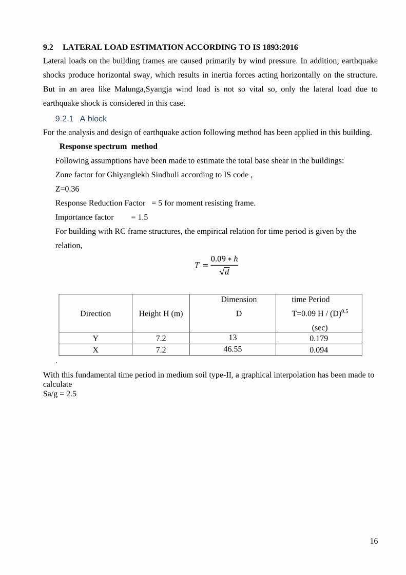
9.2 LATERAL LOAD ESTIMATION ACCORDING TO IS 1893:2016
Lateral loads on the building frames are caused primarily by wind pressure. In addition; earthquake
shocks produce horizontal sway, which results in inertia forces acting horizontally on the structure.
But in an area like Malunga,Syangja wind load is not so vital so, only the lateral load due to
earthquake shock is considered in this case.
9.2.1 A block
For the analysis and design of earthquake action following method has been applied in this building.
Response spectrum method
Following assumptions have been made to estimate the total base shear in the buildings:
Zone factor for Ghiyanglekh Sindhuli according to IS code ,
Z=0.36
Response Reduction Factor = 5 for moment resisting frame.
Importance factor = 1.5
For building with RC frame structures, the empirical relation for time period is given by the
relation,
𝑇 =0.09 ∗ ℎ
√𝑑
Direction Height H (m)
Dimension
D
time Period
T=0.09 H / (D)0.5
(sec)
Y 7.2 13 0.179
X 7.2 46.55 0.094
.
With this fundamental time period in medium soil type-II, a graphical interpolation has been made to
calculate
Sa/g = 2.5
17
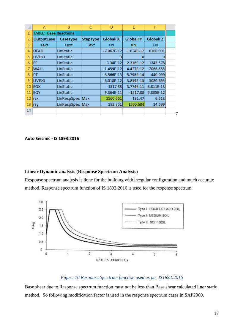
7
Auto Seismic - IS 1893:2016
Linear Dynamic analysis (Response Spectrum Analysis)
Response spectrum analysis is done for the building with irregular configuration and much accurate
method. Response spectrum function of IS 1893:2016 is used for the response spectrum.
Figure 10 Response Spectrum function used as per IS1893:2016
Base shear due to Response spectrum function must not be less than Base shear calculated liner static
method. So following modification factor is used in the response spectrum cases in SAP2000.

18
|Direction Symbol Modification Factor
X Lx 12.2
Y Ly 12.2
19
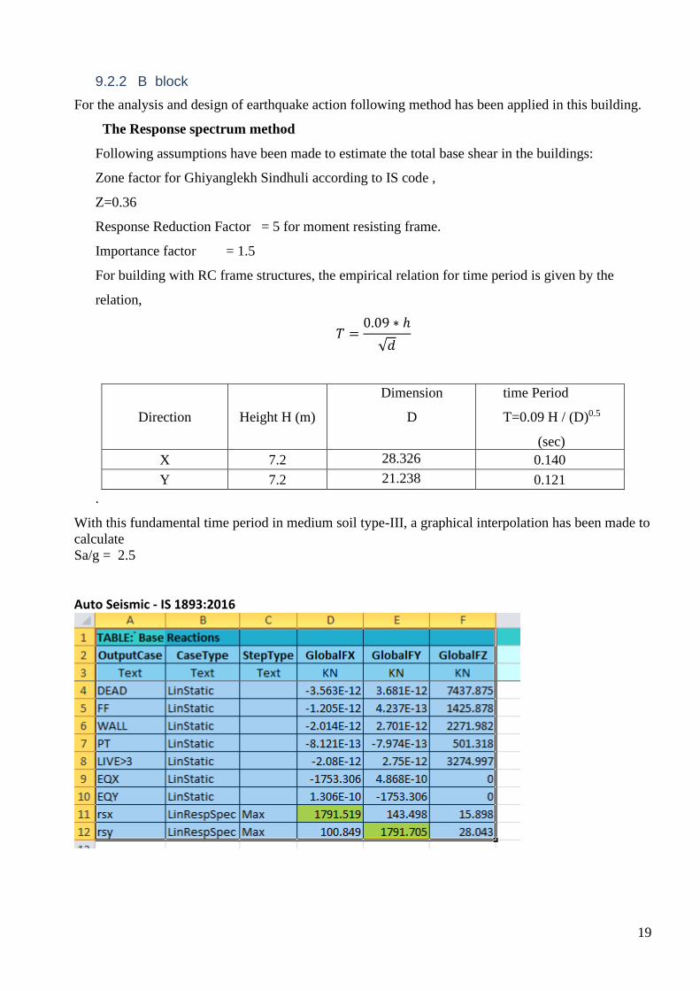
9.2.2 B block
For the analysis and design of earthquake action following method has been applied in this building.
The Response spectrum method
Following assumptions have been made to estimate the total base shear in the buildings:
Zone factor for Ghiyanglekh Sindhuli according to IS code ,
Z=0.36
Response Reduction Factor = 5 for moment resisting frame.
Importance factor = 1.5
For building with RC frame structures, the empirical relation for time period is given by the
relation,
𝑇 =0.09 ∗ ℎ
√𝑑
Direction Height H (m)
Dimension
D
time Period
T=0.09 H / (D)0.5
(sec)
X 7.2 28.326 0.140
Y 7.2 21.238 0.121
.
With this fundamental time period in medium soil type-III, a graphical interpolation has been made to
calculate
Sa/g = 2.5
Auto Seismic - IS 1893:2016
20
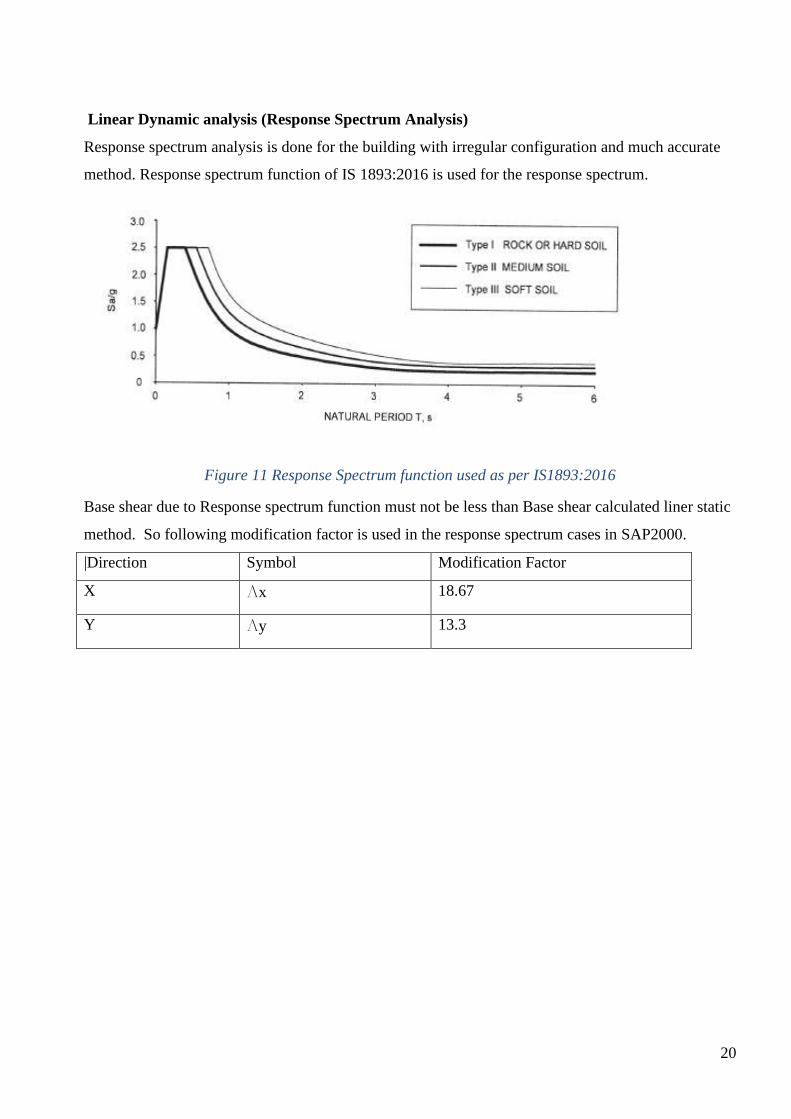
Linear Dynamic analysis (Response Spectrum Analysis)
Response spectrum analysis is done for the building with irregular configuration and much accurate
method. Response spectrum function of IS 1893:2016 is used for the response spectrum.
Figure 11 Response Spectrum function used as per IS1893:2016
Base shear due to Response spectrum function must not be less than Base shear calculated liner static
method. So following modification factor is used in the response spectrum cases in SAP2000.
|Direction Symbol Modification Factor
X Lx 18.67
Y Ly 13.3

21
9.3 LOAD CASES AND COMBINATION
9.3.1 Load Cases
Load cases are the independent loadings for which the structure is explicitly analyzed. Earthquake
forces occur in random fashion in all directions. For buildings whose lateral load resisting elements
are oriented in two principal directions, it is usually sufficient to analyze in these two principal
directions (X – and Y – direction) separately one at a time. Thus, the load cases adopted are as
follows:
i. Dead Load (DL)
ii. Live Load (LL)
iii. EQX
iv. EQY
v. RSX
vi. RSY
9.3.2 Load Combinations
Load combinations are the loadings formed by the linear combination of the independent loading
conditions. The different load cases have been combined as per IS Code .The load combinations are
as follows:
i. 1.5 DL + 1.5 LL
ii. 1.2(DL+LL+- EQ)
iii. 0.9DL+-1.5 EQ
DL= Dead Load
LL= Live load
EQ= Earthquake Load
For the dynamic analysis Earth quake load is replaced by Response spectrum Load RSX and RSY.
22
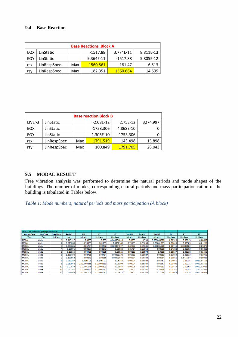
9.4 Base Reaction
Base Reactions .Block A
EQX LinStatic -1517.88 3.774E-11 8.811E-13
EQY LinStatic 9.364E-11 -1517.88 5.805E-12
rsx LinRespSpec Max 1560.561 181.47 6.513
rsy LinRespSpec Max 182.351 1560.684 14.599
Base reaction Block B
LIVE>3 LinStatic -2.08E-12 2.75E-12 3274.997
EQX LinStatic -1753.306 4.868E-10 0
EQY LinStatic 1.306E-10 -1753.306 0
rsx LinRespSpec Max 1791.519 143.498 15.898
rsy LinRespSpec Max 100.849 1791.705 28.043
9.5 MODAL RESULT
Free vibration analysis was performed to determine the natural periods and mode shapes of the
buildings. The number of modes, corresponding natural periods and mass participation ration of the
building is tabulated in Tables below.
Table 1: Mode numbers, natural periods and mass participation (A block)

23
Table 2: Mode numbers, natural periods and mass participation (B block)
24
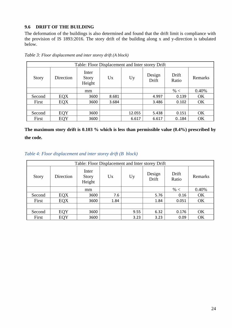
9.6 DRIFT OF THE BUILDING
The deformation of the buildings is also determined and found that the drift limit is compliance with
the provision of IS 1893:2016. The story drift of the building along x and y-direction is tabulated
below.
Table 3: Floor displacement and inter storey drift (A block)
Table: Floor Displacement and Inter storey Drift
Story Direction
Inter
Story
Height
Ux Uy Design
Drift
Drift
Ratio Remarks
mm % < 0.40%
Second EQX 3600 8.681 4.997 0.139 OK
First EQX 3600 3.684 3.486 0.102 OK
Second EQY 3600 12.055 5.438 0.151 OK
First EQY 3600 6.617 6.617 0..184 OK
The maximum story drift is 0.103 % which is less than permissible value (0.4%) prescribed by
the code.
Table 4: Floor displacement and inter storey drift (B block)
Table: Floor Displacement and Inter storey Drift
Story Direction
Inter
Story
Height
Ux Uy Design
Drift
Drift
Ratio Remarks
mm % < 0.40%
Second EQX 3600 7.6 5.76 0.16 OK
First EQX 3600 1.84 1.84 0.051 OK
Second EQY 3600 9.55 6.32 0.176 OK
First EQY 3600 3.23 3.23 0.09 OK
25
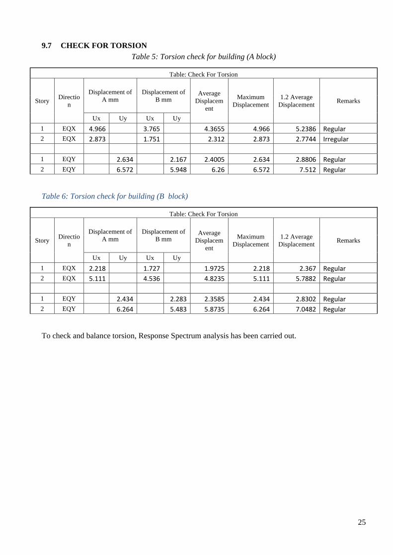
9.7 CHECK FOR TORSION
Table 5: Torsion check for building (A block)
Table: Check For Torsion
Story Directio
n
Displacement of
A mm
Displacement of
B mm Average
Displacem
ent
Maximum
Displacement
1.2 Average
Displacement Remarks
Ux Uy Ux Uy
1 EQX 4.966 3.765 4.3655 4.966 5.2386 Regular 2 EQX 2.873 1.751 2.312 2.873 2.7744 Irregular
1 EQY 2.634 2.167 2.4005 2.634 2.8806 Regular 2 EQY 6.572 5.948 6.26 6.572 7.512 Regular
Table 6: Torsion check for building (B block)
Table: Check For Torsion
Story Directio
n
Displacement of
A mm
Displacement of
B mm Average
Displacem
ent
Maximum
Displacement
1.2 Average
Displacement Remarks
Ux Uy Ux Uy
1 EQX 2.218 1.727 1.9725 2.218 2.367 Regular 2 EQX 5.111 4.536 4.8235 5.111 5.7882 Regular
1 EQY 2.434 2.283 2.3585 2.434 2.8302 Regular 2 EQY 6.264 5.483 5.8735 6.264 7.0482 Regular
To check and balance torsion, Response Spectrum analysis has been carried out.
26
10. DESIGN OF STRUCTURL MEMBERS
10.1 Design of slab
The slabs are kept in such a way that ly/lx is kept less than 2 such that it can be designed as two way
slab. The slab is designed using SAP2000 V22 and checked manually on excel sheet based on IS
456:2000 and is presented in Annex.
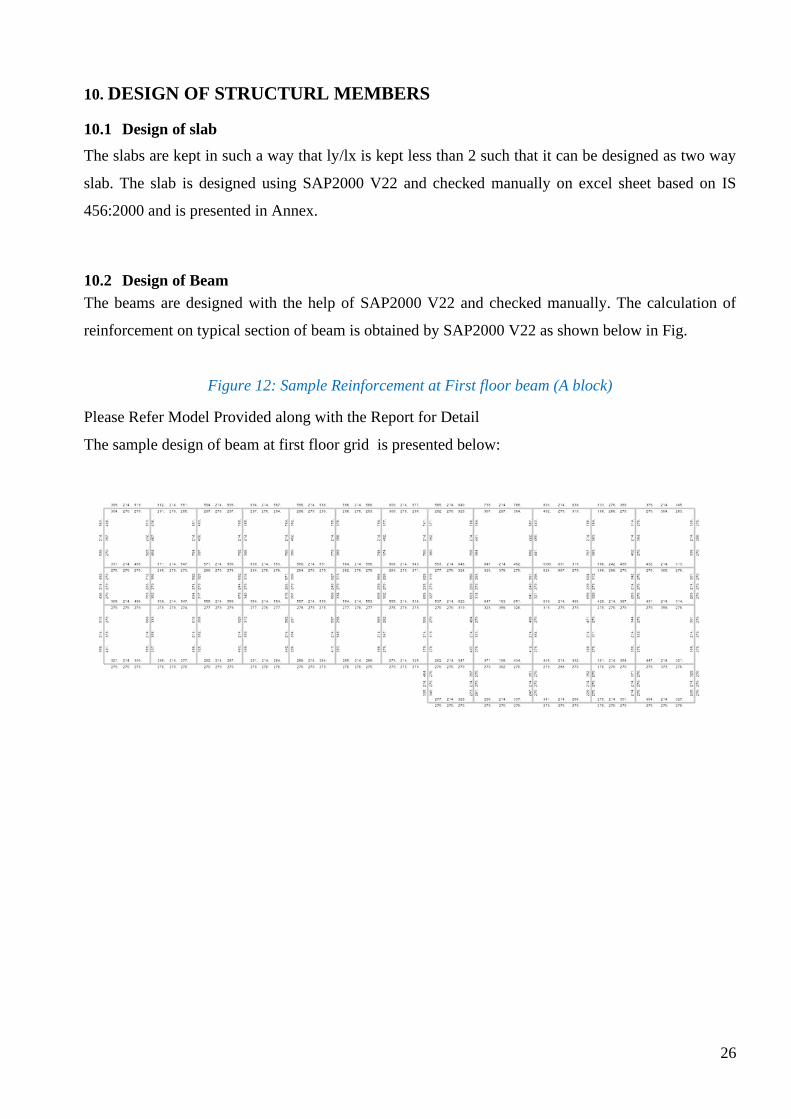
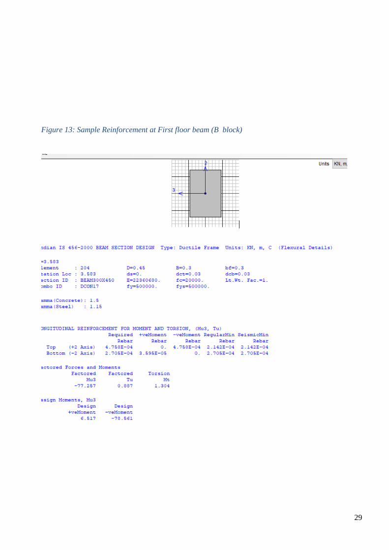
10.2 Design of Beam
The beams are designed with the help of SAP2000 V22 and checked manually. The calculation of
reinforcement on typical section of beam is obtained by SAP2000 V22 as shown below in Fig.
Figure 12: Sample Reinforcement at First floor beam (A block)
Please Refer Model Provided along with the Report for Detail
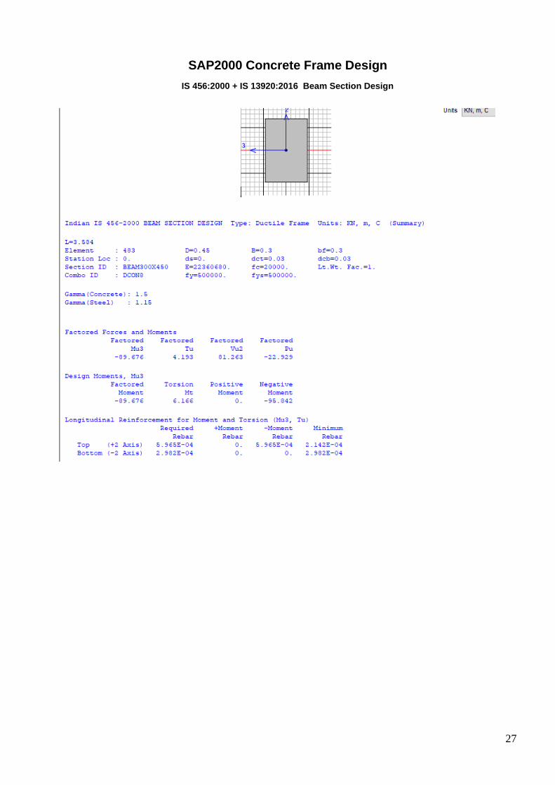
The sample design of beam at first floor grid is presented below:
27
SAP2000 Concrete Frame Design
IS 456:2000 + IS 13920:2016 Beam Section Design

28
29
Figure 13: Sample Reinforcement at First floor beam (B block)

30
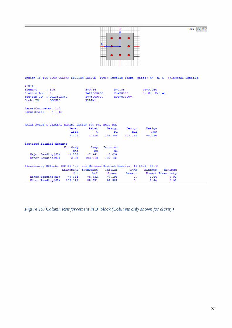
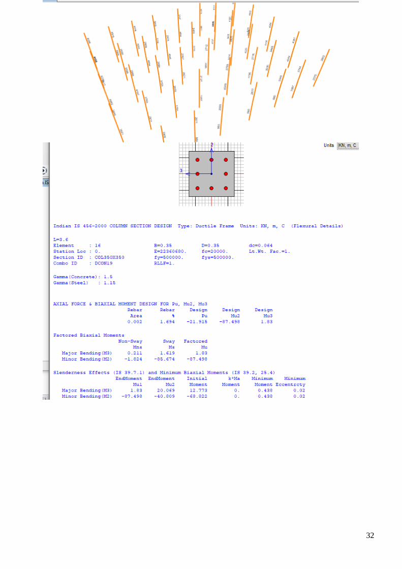
10.3 Design of Column
The rectangular columns are designed with the help of SAP2000 V22 and checked manually.
Calculation of longitudinal reinforcement of typical elements is shown below in Fig. below. The
method carried out during the structural analysis is verified with other possible methods. There is not
significant change in the design values. The interaction curve provided in literature is then used to
design these columns.
Figure 14 : Column Reinforcement in A block (Columns only shown for clarity)
Please Refer Model Provided along with the Report for Detail. Sample design of column of ground
floor at grid A1 is shown below:
31
Figure 15: Column Reinforcement in B block (Columns only shown for clarity)
32
33
10.4 Design of foundation
The foundations used in the building are of isolated type as per the requirements. The depth of the
footing is governed by one way and two way shear (punching shear). The soil type is assumed to be
of medium type. So the allowable bearing capacity of soil is taken from the soil test report. Bearing
capacity of the isolated footing is at the depth of 2 m.
Allowable bearing capacity = 225 KN/m2
The design of isolated footing has been carried out manually as per IS 456 2000 and is presented in
Annex.
10.5 Design of staircase
The staircase used in the building is of Straight flight and dog legged type. The design of staircase is
done manually using IS 456 2000 as presented in Annex.
34
11. CONCLUDING REMARKS
Reinforced concrete construction is common all over the world. It is used extensively for construction
of variety of structures such as buildings, bridges, dams, water tanks, stadium, towers, chimneys,
tunnels and so on.
Experiences from past earthquakes and extensive laboratory works have shown that a well-designed
and detailed reinforced concrete structure is suitable for earthquake resistant structure. Ductility and
strength required to resist major earthquake can be achieved by following the recommendations made
in the standard codes of practice for earthquake resistant design.
Detailing of steel reinforcement is an important aspect of structural design. Poor reinforcement
detailing can lead to structural failures. Detailing plays an important role in seismic resistant design.
In seismic resistant design, actual forces experienced by the structure are reduced and reliance is
placed on the ductility of the structure. And, ductility can be achieved by proper detailing only. Thus,
in addition to design, attention should be paid on amount, location and arrangement of reinforcement
to achieve ductility as well as strength.
Design and construction of the structure are inter – related jobs. A building behaves in a manner how
it has been built rather than what the intensions is during designing. A large percentage of structural
failures are attributed due to poor quality of construction. Therefore, quality assurance is needed in
both design and construction.
In earthquake resistant construction quality of materials and workmanship plays a very important
role. It has been observed that damages during earthquakes are largely dependent on the quality and
workmanship. Hence, quality assurance is the most important factor in the good seismic behavior of
the structure.
The strap beam has to be constructed at block B below shear wall must be associated with
monolithic and ductile performances with SMRF type.
The straight flight of staircase may belinked up to the columns by inclined beam strut
35
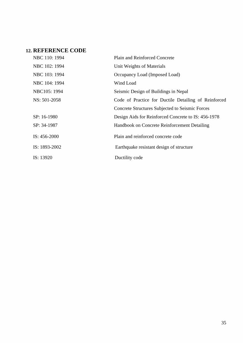
12. REFERENCE CODE
NBC 110: 1994 Plain and Reinforced Concrete
NBC 102: 1994 Unit Weights of Materials
NBC 103: 1994 Occupancy Load (Imposed Load)
NBC 104: 1994 Wind Load
NBC105: 1994 Seismic Design of Buildings in Nepal
NS: 501-2058 Code of Practice for Ductile Detailing of Reinforced
Concrete Structures Subjected to Seismic Forces
SP: 16-1980 Design Aids for Reinforced Concrete to IS: 456-1978
SP: 34-1987 Handbook on Concrete Reinforcement Detailing
IS: 456-2000 Plain and reinforced concrete code
IS: 1893-2002 Earthquake resistant design of structure
IS: 13920 Ductility code

36
ANNEX
37
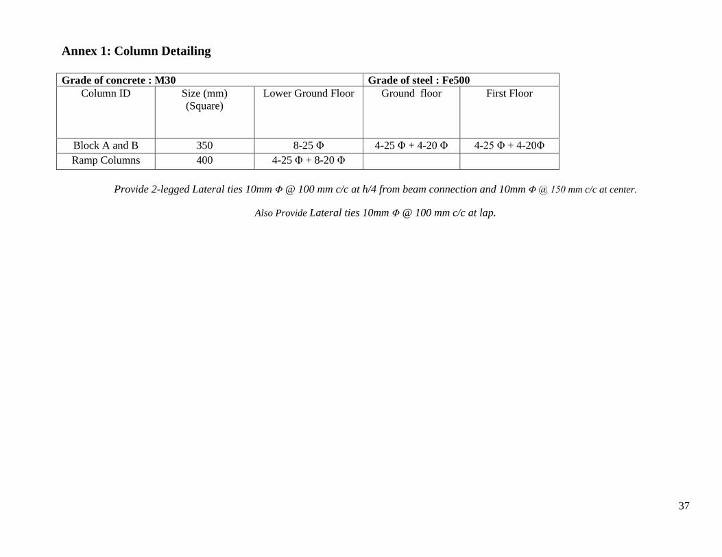
Annex 1: Column Detailing
Grade of concrete : M30 Grade of steel : Fe500
Column ID Size (mm)
(Square)
Lower Ground Floor Ground floor First Floor
Block A and B 350 8-25 Φ 4-25 Φ + 4-20 Φ 4-25 Φ + 4-20Φ
Ramp Columns 400 4-25 Φ + 8-20 Φ
Provide 2-legged Lateral ties 10mm Φ @ 100 mm c/c at h/4 from beam connection and 10mm Φ @ 150 mm c/c at center.
Also Provide Lateral ties 10mm Φ @ 100 mm c/c at lap.
38
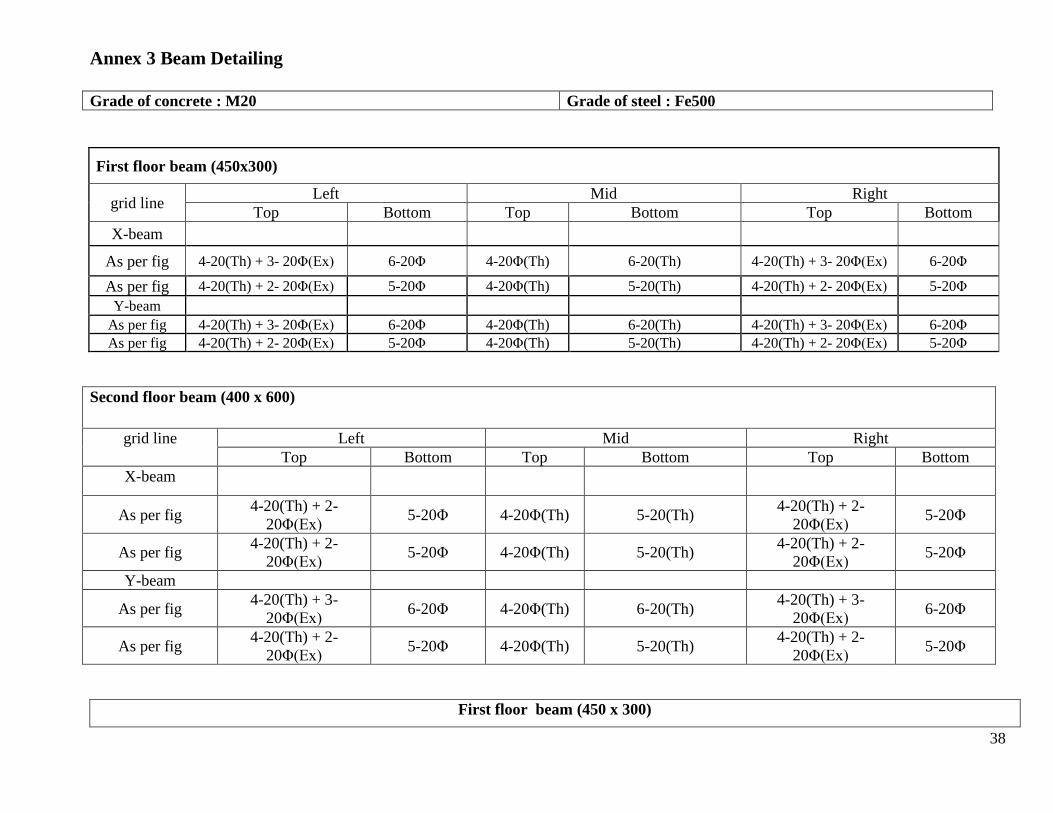
Annex 3 Beam Detailing
Grade of concrete : M20 Grade of steel : Fe500
First floor beam (450x300)
grid line Left Mid Right
Top Bottom Top Bottom Top Bottom
X-beam
As per fig 4-20(Th) + 3- 20Φ(Ex) 6-20Φ 4-20Φ(Th) 6-20(Th) 4-20(Th) + 3- 20Φ(Ex) 6-20Φ
As per fig 4-20(Th) + 2- 20Φ(Ex) 5-20Φ 4-20Φ(Th) 5-20(Th) 4-20(Th) + 2- 20Φ(Ex) 5-20Φ
Y-beam
As per fig 4-20(Th) + 3- 20Φ(Ex) 6-20Φ 4-20Φ(Th) 6-20(Th) 4-20(Th) + 3- 20Φ(Ex) 6-20Φ
As per fig 4-20(Th) + 2- 20Φ(Ex) 5-20Φ 4-20Φ(Th) 5-20(Th) 4-20(Th) + 2- 20Φ(Ex) 5-20Φ
Second floor beam (400 x 600)
grid line Left Mid Right
Top Bottom Top Bottom Top Bottom
X-beam
As per fig 4-20(Th) + 2-
20Φ(Ex) 5-20Φ 4-20Φ(Th) 5-20(Th)
4-20(Th) + 2-
20Φ(Ex) 5-20Φ
As per fig 4-20(Th) + 2-
20Φ(Ex) 5-20Φ 4-20Φ(Th) 5-20(Th)
4-20(Th) + 2-
20Φ(Ex) 5-20Φ
Y-beam
As per fig 4-20(Th) + 3-
20Φ(Ex) 6-20Φ 4-20Φ(Th) 6-20(Th)
4-20(Th) + 3-
20Φ(Ex) 6-20Φ
As per fig 4-20(Th) + 2-
20Φ(Ex) 5-20Φ 4-20Φ(Th) 5-20(Th)
4-20(Th) + 2-
20Φ(Ex) 5-20Φ
First floor beam (450 x 300)

39
grid line Left Mid Right
Top Bottom Top Bottom Top Bottom
All Beams 4-20(Th) + 2- 20Φ(Ex) 5-20Φ 4-20Φ(Th) 5-20(Th)
4-20(Th) + 2-
20Φ(Ex) 5-20Φ
Provide 2-legged vertical stirrup 10mm Φ 100 mm c/c at 2D- from support and 10mm Φ @ 150 mm c/c at center.
Also provide 2-legged vertical stirrup 10mm Φ @ 100 mm c/c at lap

40
Annex 4: Design of Foundation
The foundation is of isolated and combined type. The footing has been designed manually as per
IS 456 2000. Sample design calculation for footing type F1 is shown below:
see Pdf attached
41
Similarly calculations were done for other footing types and shown in drawing.
Annex 5: Design of Slab
See Pdf attached
Annex 6: Design of Staircase
See Pdf attached
Annex 7: Design of Shear wall with strap beam
See Pdf attached
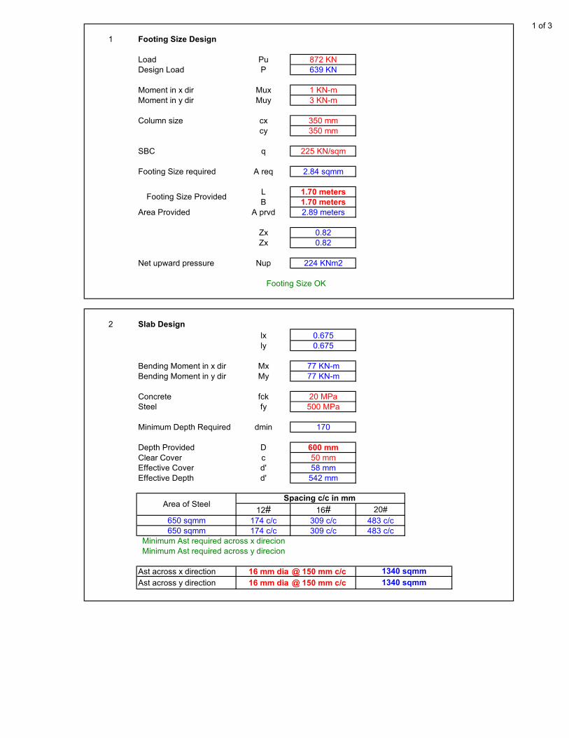
Design Of Isolated Footing 1 of 3
1 Footing Size Design
Load Pu 872 KN
Design Load P 639 KN
Moment in x dir Mux 1 KN-m
Moment in y dir Muy 3 KN-m
Column size cx 350 mm
cy 350 mm
SBC q 225 KN/sqm
Footing Size required A req 2.84 sqmm
L 1.70 meters
B 1.70 meters
Area Provided A prvd 2.89 meters
Zx 0.82
Zx 0.82
Net upward pressure Nup 224 KNm2
2 Slab Design
lx 0.675
ly 0.675
Bending Moment in x dir Mx 77 KN-m
Bending Moment in y dir My 77 KN-m
Concrete fck 20 MPa
Steel fy 500 MPa
Minimum Depth Required dmin 170
Depth Provided D 600 mm
Clear Cover c 50 mm
Effective Cover d' 58 mm
Effective Depth d' 542 mm
12# 16# 20#
650 sqmm 174 c/c 309 c/c 483 c/c
650 sqmm 174 c/c 309 c/c 483 c/c
Ast across x direction 16 mm dia @ 150 mm c/c
Ast across y direction 16 mm dia @ 150 mm c/c
Minimum Ast required across y direcion
1340 sqmm
1340 sqmm
Footing Size OK
Footing Size Provided
Area of Steel
Minimum Ast required across x direcion
Spacing c/c in mm

Design Of Isolated Footing 2 of 3
3
Vu1 76 KN
ζv 0.083 MPa
ζc 0.260 MPa
Vc1 240 KN
4 One Way Shear along y direction
Vu1 76 KN
ζv 0.083 MPa
ζc 0.260 MPa
Vc1 240 KN
5 Two Way Shear
Vu2 705 KN
ζv 0.364 MPa
ks*ζc 1.118 MPa
Vc1 2162 KN
One Way Shear Check OK
One Way Shear along x direction
One Way Shear Check OK
Two Way Shear Check OK
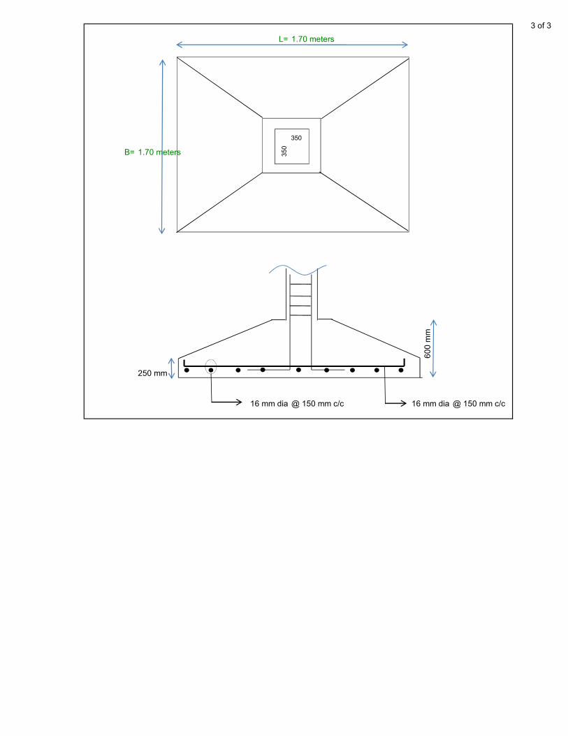
Design Of Isolated Footing 3 of 3
L= 1.70 meters
350
B= 1.70 meters 350
16 mm dia @ 150 mm c/c 16 mm dia @ 150 mm c/c
250 mm
60
0 m
m

centre to centre distance of walls
5.13 m
Riser (R) = 150 mm
Thread (T) = 250 mm
Concrete grade (fck) = 20 MPa
Rebar grade (fy) = 500 MPa
Assume ,
Thickness of waist slab (t) = 170 mm
Overall thickness (D) = 200 mm
Let us find load per metre horizontal width of stairs
Weight of waist salb = D*sqrt*(1+(R/T)^2)*25)
= 5.83 KN/m
Weight of steps =1/2*R*25
= 1.88 KN/m
Therefore Dead Load = 7.71 KN/m
Finishing Load = 1.50 KN/m
In going portion total DL with finishing,
9.21 KN/m
In Landing portion
Dead Load = 4.25 KN/m
Finishing Load = 1.50 KN/m
Total Dead load =
Effective Span =
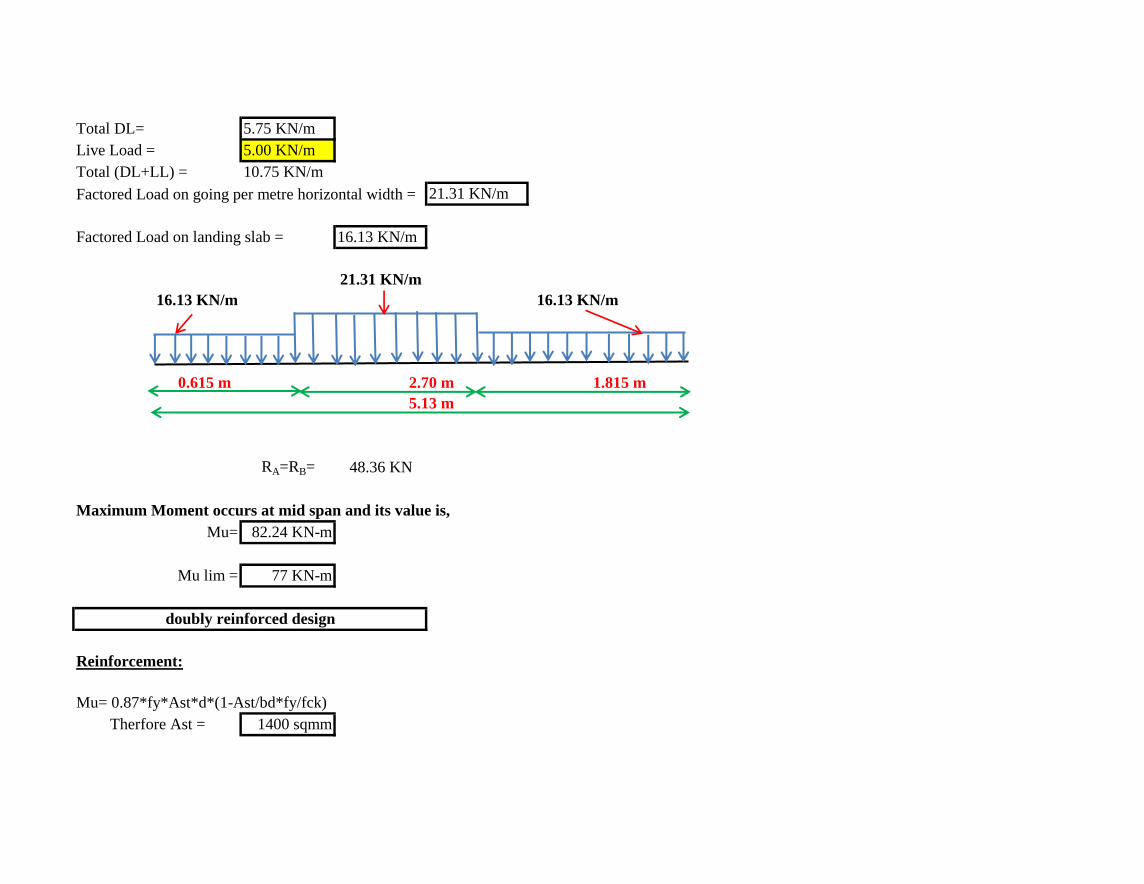
Total DL= 5.75 KN/m
Live Load = 5.00 KN/m
Total (DL+LL) = 10.75 KN/m
Factored Load on going per metre horizontal width = 21.31 KN/m
Factored Load on landing slab = 16.13 KN/m
21.31 KN/m
16.13 KN/m 16.13 KN/m
RA=RB= 48.36 KN
Maximum Moment occurs at mid span and its value is,
Mu= 82.24 KN-m
Mu lim = 77 KN-m
Reinforcement:
Mu= 0.87*fy*Ast*d*(1-Ast/bd*fy/fck)
Therfore Ast = 1400 sqmm
doubly reinforced design
0.615 m 2.70 m 1.815 m
5.13 m
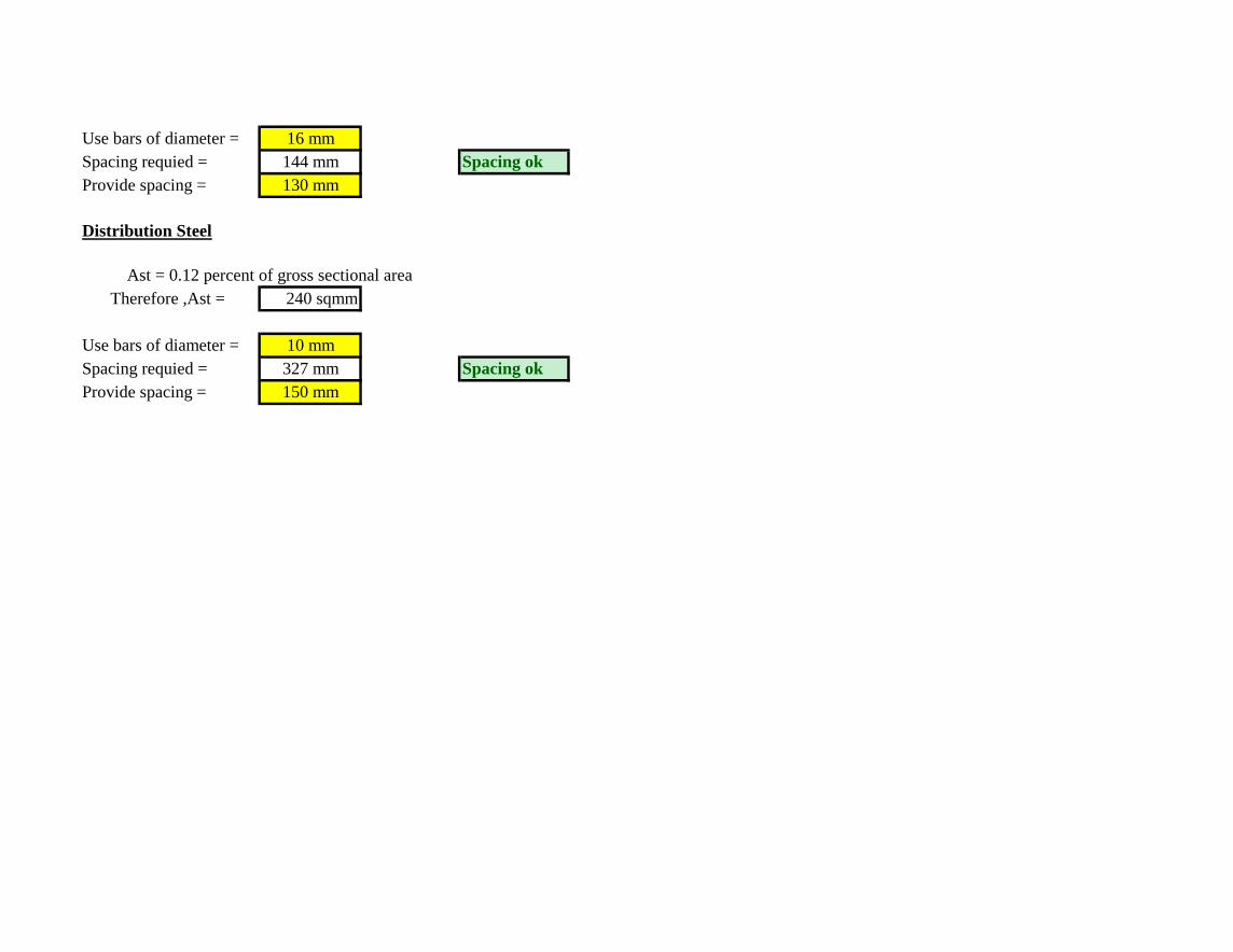
Use bars of diameter = 16 mm
Spacing requied = 144 mm Spacing ok
Provide spacing = 130 mm
Distribution Steel
Therefore ,Ast = 240 sqmm
Use bars of diameter = 10 mm
Spacing requied = 327 mm Spacing ok
Provide spacing = 150 mm
Ast = 0.12 percent of gross sectional area
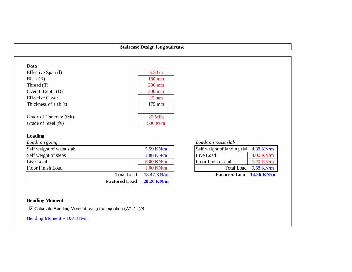
Data
Effective Span (l) 6.50 m
Riser (R) 150 mm
Thread (T) 300 mm
Overall Depth (D) 200 mm
Effective Cover 25 mm
Thickness of slab (t) 175 mm
Grade of Concrete (fck) 20 MPa
Grade of Steel (fy) 500 MPa
Loading
Loads on going Loads on waist slab
Self weight of waist slab 5.59 KN/m Self weight of landing slab 4.38 KN/m
Self weight of steps 1.88 KN/m Live Load 4.00 KN/m
Live Load 5.00 KN/m Floor Finish Load 1.20 KN/m
Floor Finish Load 1.00 KN/m Total Load 9.58 KN/m
Total Load 13.47 KN/m Factored Load 14.36 KN/m
Factored Load 20.20 KN/m
Bending Moment
Bending Moment = 107 KN-m
Staircase Design long staircase
Calculate Bending Moment using the equation (W*L*L )/8

Reaction
to be used as UDL = 66 KN
For Fe 500, xu,lim = 0.46d
Hence, Mu.lim = 0.1336fck*b*d2 82 KN-m
The section is doubly reinforced. Please recheck.
Area of Main Steel
Ast required 1939 sqmm
Spacing
Diameter of bar in mm (ø) 16
Spacing required in mm 104 c/c
Spacing provided in mm 100 c/c
Provded Main Steel: 16 mm ø bars @ 100 c/c
Area of Distribution Steel
Ast required 300 sqmm
Singly/Doubly Reinforced CheckMu,lim = 0.36 fck b xu,lim(d-0.42 xu,lim)
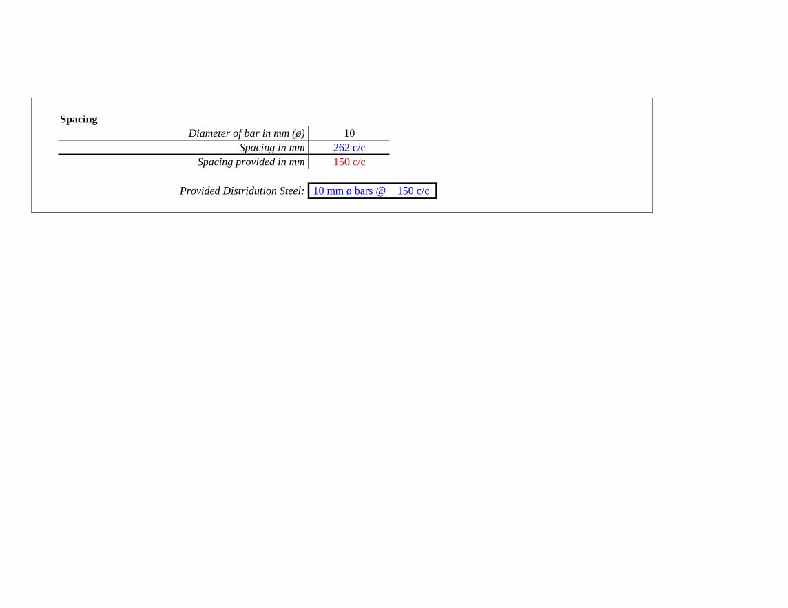
Spacing
Diameter of bar in mm (ø) 10
Spacing in mm 262 c/c
Spacing provided in mm 150 c/c
Provided Distridution Steel: 10 mm ø bars @ 150 c/c
Sheet1
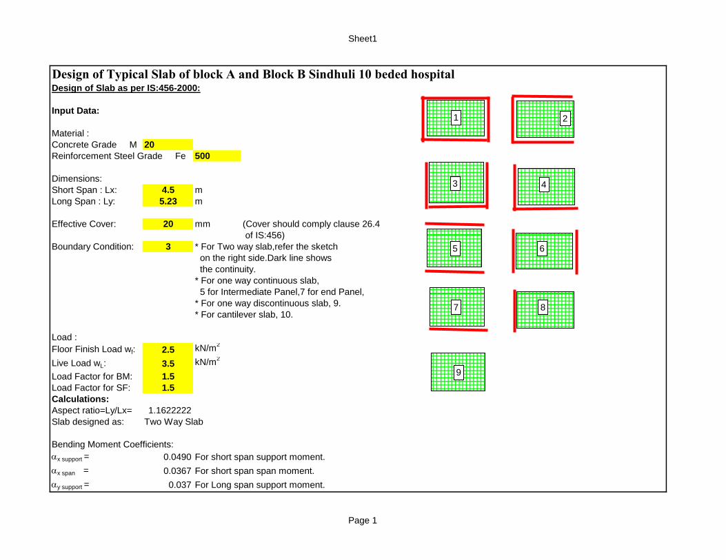
Design of Typical Slab of block A and Block B Sindhuli 10 beded hospitalDesign of Slab as per IS:456-2000:
Input Data:
Material :
Concrete Grade M 20
Reinforcement Steel Grade Fe 500
Dimensions:
Short Span : Lx: 4.5 m
Long Span : Ly: 5.23 m
Effective Cover: 20 mm (Cover should comply clause 26.4
of IS:456)
Boundary Condition: 3 * For Two way slab,refer the sketch
on the right side.Dark line shows
the continuity.
* For one way continuous slab,
5 for Intermediate Panel,7 for end Panel,
* For one way discontinuous slab, 9.
* For cantilever slab, 10.
Load :
Floor Finish Load wf: 2.5 kN/m2
Live Load wL: 3.5 kN/m2
Load Factor for BM: 1.5
Load Factor for SF: 1.5
Calculations:
Aspect ratio=Ly/Lx= 1.1622222
Slab designed as: Two Way Slab
Bending Moment Coefficients:
ax support = 0.0490 For short span support moment.
ax span = 0.0367 For short span span moment.
ay support = 0.037 For Long span support moment.
9
1 2
3 4
5 6
7 8
Page 1
Sheet1
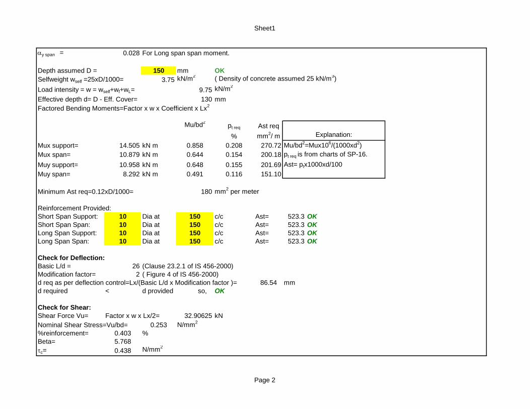
ay span = 0.028 For Long span span moment.
Depth assumed D = 150 mm OK
Selfweight wself =25xD/1000= 3.75 kN/m2
( Density of concrete assumed 25 kN/m3)
Load intensity = w = wself+wf+wL= 9.75 kN/m2
Effective depth d= D - Eff. Cover= 130 mm
Factored Bending Moments=Factor x w x Coefficient x Lx2
Mu/bd2
pt req Ast req
% mm2/ m
Mux support= 14.505 kN m 0.858 0.208 270.72 Mu/bd2=Mux10
6/(1000xd
2)
Mux span= 10.879 kN m 0.644 0.154 200.18 pt req is from charts of SP-16.
Muy support= 10.958 kN m 0.648 0.155 201.69 Ast= ptx1000xd/100
Muy span= 8.292 kN m 0.491 0.116 151.10
Minimum Ast req=0.12xD/1000= 180 mm2 per meter
Reinforcement Provided:
Short Span Support: 10 Dia at 150 c/c Ast= 523.3 OK
Short Span Span: 10 Dia at 150 c/c Ast= 523.3 OK
Long Span Support: 10 Dia at 150 c/c Ast= 523.3 OK
Long Span Span: 10 Dia at 150 c/c Ast= 523.3 OK
Check for Deflection:
Basic L/d = 26 (Clause 23.2.1 of IS 456-2000)
Modification factor= 2 ( Figure 4 of IS 456-2000)
d req as per deflection control=Lx/(Basic L/d x Modification factor )= 86.54 mm
d required < d provided so, OK
Check for Shear:
Shear Force Vu= Factor x w x Lx/2= 32.90625 kN
Nominal Shear Stress=Vu/bd= 0.253 N/mm2
%reinforcement= 0.403 %
Beta= 5.768
tc= 0.438 N/mm2
Explanation:
Page 2
Sheet1
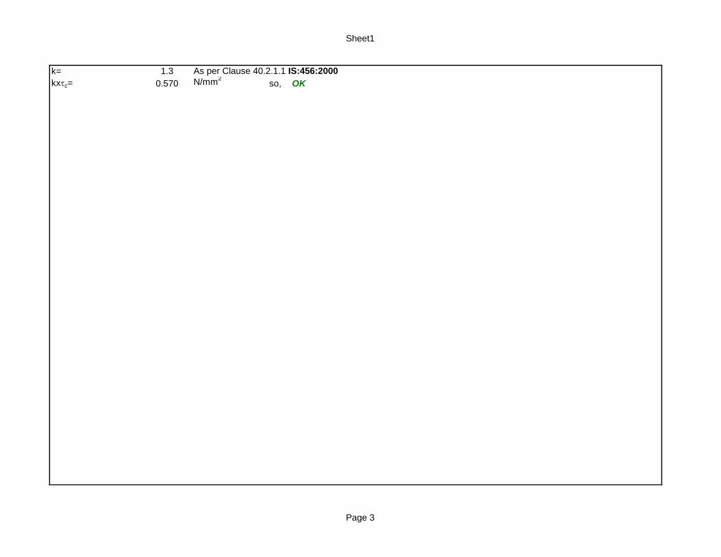
k= 1.3 As per Clause 40.2.1.1 IS:456:2000
kxtc= 0.570 N/mm2
so, OK
Page 3

Sheet1
Page 4

Sheet1
Page 5

Sheet1
Page 6

Sheet1
Page 7

Sheet1
Page 8