structural analysis in a conceptual design framework - … · structural analysis in a conceptual...
TRANSCRIPT

American Institute of Aeronautics and Astronautics
1
Structural Analysis in a Conceptual Design Framework
Sharon L. Padula,* Jay H. Robinson,
† and Lloyd B. Eldred
‡
NASA Langley Research Center, Hampton, VA, 23681
Supersonic aircraft designers must shape the outer mold line of the aircraft to improve
multiple objectives, such as mission performance, cruise efficiency, and sonic-boom
signatures. Conceptual designers have demonstrated an ability to assess these objectives for
a large number of candidate designs. Other critical objectives and constraints, such as
weight, fuel volume, aeroelastic effects, and structural soundness, are more difficult to
address during the conceptual design process. The present research adds both static
structural analysis and sizing to an existing conceptual design framework. The ultimate goal
is to include structural analysis in the multidisciplinary optimization of a supersonic aircraft.
Progress towards that goal is discussed and demonstrated.
Nomenclature
CFD = computational fluid dynamics
CG = center of gravity
DOE = design of experiments
GUI = graphical user interface
FEM = finite-element model
MOS = margin of safety
OML = outer mold line of aircraft
PCL = Patran command language
VSP = Vehicle Sketch Pad
I. Introduction
he conceptual design of an efficient and economically viable supersonic jet aircraft requires multidisciplinary
and multifidelity analysis and optimization. The outer mold line (OML) must be shaped for efficient operation
at subsonic, transonic, and supersonic speeds, while accounting for fuel volume, center of gravity (CG) placement,
sonic-boom production, and a host of other considerations. The conceptual design process is challenging even with
high-powered computer resources and validated analysis software. One significant obstacle in conceptual design is
the production and maintenance of consistent models (i.e., the creation of input files for each analysis code as the
geometry is modified). Another significant obstacle involves the creation and analysis of internal structural models
and the adjustment of those models to account for changes in fuselage shaping, landing-gear placement, wing
geometry, and other similar conceptual design changes.
An integrated process for multifidelity, multidisciplinary, design optimization and analysis of supersonic
transports is described in Refs. 1 and 2. This process is implemented in the ModelCenter framework,§ which is a
product of Phoenix Integration.3 The conceptual design process includes propulsion system design and analysis,
mission performance and takeoff analysis, and noise assessment. Several new features facilitate geometry
modification and geometry visualization, while automatically creating consistent inputs for all analyses, including
watertight OML and volume grids for computational fluid dynamics (CFD) analysis. However, the conceptual
design process that is described in Ref. 1 uses empirical weight estimates in lieu of static structural analysis.
* Senior Research Engineer, Aeronautics Systems Analysis Branch, MS 442, Associate Fellow AIAA.
† Senior Research Engineer, Aeronautics Systems Analysis Branch, MS 442.
‡ Senior Research Engineer, Vehicle Analysis Branch, MS 451, Senior Member AIAA.
§ The use of trademarks or names of manufacturers in this report is for accurate reporting and does not constitute an
official endorsement, either expressed or implied, of such products or manufacturers by the National Aeronautics
and Space Administration.
T
https://ntrs.nasa.gov/search.jsp?R=20120007424 2018-07-09T04:53:35+00:00Z

American Institute of Aeronautics and Astronautics
2
The addition of structural analysis to the existing conceptual design and optimization process is an important
next step. Ideally, the updated process will quickly discriminate between promising designs and non-viable designs
(e.g., those with insufficient space for necessary support structure). Given a promising design, the process will create
a finite-element model (FEM) and estimate the total weight, CG, and maximum wing-tip deflections. As an option,
the process will execute modal analysis, static aeroelasticity, and sizing optimization. Moreover, the process will
automatically create an FEM with sufficient detail to guide further analysis and preliminary design by experts in
structures, aeroelastics, and materials.
II. Enhanced Conceptual Design Process
Figure 1 shows views of the conceptual design process that is implemented in the ModelCenter framework. Each
of the grey boxes on the right side of Fig. 1(a) represents a top-level analysis component, such as propulsion or
performance analysis. These ModelCenter components are activated and deactivated by user inputs, which are
shown in green. For example, the noise variable is set to false; thus, the community noise component is deactivated.
The top-level components in Fig. 1(a) can be expanded to show details at the lower levels. For example, Fig. 1(b)
shows some details of the structures component. This component executes an initial static analysis followed by one
of four choices: sizing optimization, modal analysis, aeroelastic analysis, or no additional analysis. Again, these
analysis paths are selected through the top-level inputs (e.g., note that the structures variable is set to taxi loads).
Reference 1 documents the conceptual design process and discusses many advantages to using commercial
framework software. One significant advantage is the ability to set up a wide variety of iterative processes and
thereby implement trade studies, design of experiment (DOE) studies, and multidisciplinary optimization tasks.
Each cycle of the iterative process automatically changes the geometric variables, repeats analysis components, links
component outputs to subsequent component inputs, and collects the final output values. The ModelCenter
framework provides a simple and flexible mechanism for linking the results of one analysis with the inputs to the
(a) Top level of analysis components (b) Details of structures component
Figure 1. Views of the conceptual design process implemented in ModelCenter framework.

American Institute of Aeronautics and Astronautics
3
next analysis. The framework software handles all of the data manipulation and allows the conceptual designer to
focus on the design task.
III. Structural Analysis
This present paper discusses the addition of structural analysis to the
conceptual design process that is pictured in Fig. 1 and described in Ref. 1.
A. Goals
The overall goal of this research is to identify viable structural designs at
the conceptual design stage. To achieve this goal, the design process must be
modified to include the following:
1) Automatic generation of an internal structural model with all
elements connected, all loads applied, and no elements outside of the
OML.
2) FEM generation with the results of static analysis available in
minutes.
3) FEM optionally modified for reuse for sizing optimization or modal
analysis.
4) Static aeroelastic analysis for a matrix of flight conditions as an
option.
5) Parsed output files with selected results available to conceptual
designers or for iterative processes.
6) Input and output files available for further study.
7) Generated models with the appropriate fidelity for conceptual design
tasks that also can serve as baseline models for preliminary design
tasks.
B. Possible Approaches
Several existing approaches for adding structural analysis to the
conceptual design process were considered before the current approach shown
in Fig. 2 was implemented. None of the pre-existing approaches met all of the
stated goals.
The most common approach is to manually create and execute the FEM.
For example, an analyst can use the Patran and Nastran software, both
products of MSC Software Corporation, to import an existing graphics
specification file (e.g., a file in IGES format), create an internal structure,
mesh the structure, and complete the analysis.4-6
This approach is slow and
requires a high level of structural expertise and familiarity with the Patran
software and the Patran graphical user interface (GUI). Whenever the OML
changes, a new graphics specification file is produced, and the whole process
must be repeated manually. Moreover, because some of the required details
are not contained in the graphics file, several other output files must be
consulted. The merging of information from many sources is a frequent cause
of input errors and can lead to inconsistency between the structural results and
the results from other disciplinary analyses such as CFD.
Another common approach is to use a specialized language to sketch the
internal structure. Both the RapidFEM software, a product of M4
Engineering, and AML software, a product of Technosoft, Inc., are
commercially available products that can be used with this approach. The
RapidFEM software has been demonstrated as part of an integrated
framework.7 The AML software has been integrated into its own framework,
called AMRaven, and used in aircraft design and shape optimization
research.8,9
Thus, both software products are capable of generating an FEM
and are candidates for use in this research.10
Both software products can be applied to a range of different aircraft
types. The AMRaven framework provides convenient parameterized geometry, and the RapidFEM software can
(a ) Conceptual geometry in VSP
(b ) Converted to OML in Patran
(c ) Internal structure created
Figure 2. Steps for adding structural analysis
to the conceptual design process.

American Institute of Aeronautics and Astronautics
4
perform static aeroelastic analysis for a matrix of flight conditions.7-10
One drawback to these approaches is that both
software products use special-purpose languages that are relatively new and not widely available. More
significantly, both approaches require a level of structural expertise that may not reside in a conceptual design team.
C. Implementation Details
The current approach to adding structural analysis to the conceptual design process was implemented by using
the ModelCenter framework, the MSC Software products (i.e., Patran and Nastran), and the Hypersizer software,
which is a product of Collier Research.11
These software products are widely used within NASA.
Figure 2 illustrates the steps to this approach. The ModelCenter framework links outputs from the geometry
component to the structures component. The structures component imports the conceptual geometry as a set of
airfoil and fuselage cross-sections that define the OML. This information is used to produce Patran command
language (PCL) code that defines both an internal structure and the flat-plate aerodynamic surfaces.
Figures 1 through 3 illustrate the interaction between the ModelCenter framework and the Patran software. In
addition to the OML geometry, several inputs are needed to guide the creation of the FEM. The required inputs
include the number of stringers in each section of the wing, the location of the landing gear, the weight and CG of
the fuel, and other details. Using the ModelCenter framework, the conceptual designer can type in an estimate for
each input, or accept the default value, or create links between the outputs from other analysis components and the
structures component. For example, Fig. 3(a) shows that the weight of the fuel is provided through a link between
the Lofi_weight component and the structures component. Both components use the framework variable fuel.
Figure 3(b) contains a section of Patran PCL code that is automatically generated by the structures component
and Fig. 3(c) shows some of the input and output values that are visible in the ModelCenter framework. Notice that
the weight of the fuel, 43,785 lb, has been captured from a ModelCenter framework variable called fuel and has
been assigned to a Patran variable called nsm_fuel. In a similar manner, all of the information that is required to
create a consistent FEM is captured in the Patran PCL language. The resulting Patran session file and Nastran bulk
data file are executed in the ModelCenter framework. Diagnostic output information, such as the structural weight,
the maximum deflection, and the aircraft CG can be parsed from the Nastran output files and made available in the
ModelCenter framework. For example, the total weight of the vehicle in pounds (tot_wt) and the maximum
downward deflection in inches (ztip) can be seen in Fig. 3(c). Moreover, the entire Patran PCL input file and the
Nastran output file can be viewed in a “large data monitor” window that is similar to that pictured in Fig. 3(b).
(a) Link editor in ModelCenter.

American Institute of Aeronautics and Astronautics
5
(b) Patran input file fragment.

American Institute of Aeronautics and Astronautics
6
(c ) Sample input and output values in ModelCenter.
D. Assumptions and Challenges
Numerous challenges must be overcome to add structural analysis to the conceptual design process. One
significant challenge is the need to create Patran PCL code (see Fig. 3(b)) that is robust to changes in the shape of
the OML or to changes in the number of cross-sections that are used to describe an OML. A typical user-generated
Patran session file contains many instances of specific element numbers or geometry specifiers. The framework-
generated session file must replace all of the specific items with Patran variables and arrays, so that the PCL code is
adaptable to changes in the inputs. Moreover, an engineer can use the Patran GUI to determine the top surface of the
wing from the bottom surface by inspection, but a flexible session file must include tests to determine the surface
order. Section IV illustrates the types of results that can be automatically generated. Section V demonstrates the
success of this approach with a large DOE; the numbers of successes and the causes of the failures are reported.
A key to meeting the goals and overcoming the challenges that are mentioned earlier is to limit the scope of the
research project. For example, the present project focuses on supersonic business jet design. The structural layouts
of several supersonic fighter jets and the SST Concorde are available. Based on these existing supersonic designs, a
classic metallic (i.e., black aluminum) configuration with frames, spars, stringers, and stiffened panels is selected.
Figure 3. Coordination between ModelCenter and MSC software products.

American Institute of Aeronautics and Astronautics
7
The wing design outboard of the landing gear location is a classic thin wing that connects to a typical wing/body
configuration inboard of the landing gear. All designs have two wing spars and one kicker spar, a single T-tail, and
fuselage-mounted engines, but the number of stiffeners in each section can be varied. The number of passengers and
crew can be varied, but all passenger-related payload is located in the portion of the fuselage that is located ahead of
the wing box. Figure 4 shows the top view of the baseline design with main wing skins removed.
Figure 4. Top view of the baseline supersonic business jet design.
IV. Sample Results
The current approach assumes a class of aircraft, for example, supersonic business jets, and makes assumptions
about the internal structure that is appropriate for that class. Within that class, the conceptual designer should be able
to define a new OML, make large changes to an existing OML, change mission or propulsion specifications, and
assess the effect of those changes on the structure. This section shows some typical results for a supersonic business
jet.
Figure 5 shows the Von Mises shell force resultant due to lateral taxi loads. Color contours indicate the high
stress areas in the wing and fuselage skins; these surfaces are modeled with aluminum plates. The horizontal and
vertical tails and pylons are shown as white shapes that are outlined in blue; these surfaces are modeled with
composite plates to increase their bending stiffness. Notice that the higher stress levels occur where the engine
pylons attach to the fuselage and where the landing gear attaches to the wing box.
Results similar to those in Fig. 5 can be studied for all bar elements and shell elements. These resultant forces
become the inputs to the structural sizing code, Hypersizer. The forces that are shown in Fig. 5 are quite low; thus,
the Hypersizer optimization is likely to reduce the weight of the structure.
The Hypersizer software uses a simplified combinatorial optimization process.11
All of the elements in the FEM
are sorted into groups. For example, the baseline case defines seven Hypersizer groups: fuselage skins, wing skins,
webs, frame caps, landing gear, fuselage frames, and tail beams. Each group is sized by enumerating combinations
of materials and structural concepts, beginning with the lightest choices. For example, the landing-gear elements are
aluminum tubes with five choices of material thickness and six choices of tube radius. The heuristic optimization
process tries combinations of thickness and tube radius and terminates when the margin of safety (MOS) constraints
are satisfied or all combinations have been tried. Higher fidelity results are available if the numbers of materials,
structural concepts, groups, and load cases are increased, but the computational cost increases as the number of
combinations increases.

American Institute of Aeronautics and Astronautics
8
Figure 5. Static analysis results for the baseline case (color contours denote shell forces in psi).
Figure 6 shows the displacements that result from vertical taxi loads; Fig. 6(a) shows the displacements that are
computed prior to the Hypersizer optimization, and Fig. 6(b) shows the same displacements after the Hypersizer
optimization. The deflected shape is shown with color contours; the undeflected mesh is shown in dark blue. For the
baseline case, the optimization process has improved the design by reducing the total weight from 122,800 lb to
87,500 lb and by reducing the maximum deflection from 10.3 in. to 5.9 in. These results are preliminary because
they are based on a relatively small number of sizing variables and on two load cases; however, they do provide
conceptual designers with a credible way for comparing competing designs.
(a) Initial results. (b) Results after structural sizing.
Figure 6. Static analysis results for the baseline case. Color contours denote displacement in inches.

American Institute of Aeronautics and Astronautics
9
Figure 7 shows representative results from a modal analysis that was applied to the FEM created by the
Hypersizer optimization. Twenty modes were calculated; the first six modes represent rigid body motion, as
expected. The next 14 modes represent typical aircraft bending and torsion modes. For example, mode 7 and mode 9
are pictured in Figs. 7(a) and 7(b), respectively. Mode 7 has a frequency of 1.4 Hz and shows torsion of the vertical
tail. Mode 9 has a frequency of 2.8 Hz and shows wing and horizontal tail bending. Results such as these can be
used to assess the structure and to identify and correct minor errors in the automatically created FEM. In the case of
the modes that are shown in Fig. 7, the frequencies are quite low and suggest that the structure should be stiffened.
(a) Mode 7.
(b) Mode 9.
Figure 7. Modal analysis results for the baseline configuration.

American Institute of Aeronautics and Astronautics
10
Figure 8 shows the Hypersizer results after the initial structural sizing optimization. Notice the red bars in both
the pylon frame and the wing box frame. These bars have an unacceptable MOS. A similar plot of the shell elements
would show that the fuselage skin has a negative MOS. These results are typical of the automatically generated
Hypersizer output. For conceptual design purposes, a comparison of structural weight after a Hypersizer
optimization is recommended to evaluate one design against another. However, the results that are shown in Fig. 8
are based on a limited set of combinatorial variables. Moreover, only two static analysis load cases were used to size
the structure. Adding aeroelastic load cases that span the mission envelope would be necessary to obtain more
credible sizing results. The supersonic conceptual design process includes an aeroelastic analysis that was
implemented with MSC/Nastran flight loads software, but this capability needs further testing and development.
These results demonstrate the successful addition of the Hypersizer software to the Model Center framework.
The results indicate acceptable effectiveness of the limited initial set of controls that were implemented. A vehicle
sizing engineer was able to further reduce the mass of the aircraft structure by 50 percent by making a few changes
to the design limits and panel buckling lengths. Incorporation of these insights into the baseline process is currently
underway and should be accomplished in the short term. In the longer term, providing feedback on various types of
critical regions, including those that are oversized, undersized, or highly stressed, will assist sizing engineers, loads
engineers, and geometry creators. The repartitioning of sizing regions to isolate sub-regions with different sizing
requirements (e.g., the landing-gear and the pylon attachment zones) is also under discussion.
V. Design of Experiments
The success of this research can be judged against the goals that are stated in section III. Several of those goals
involve the automatic creation of an FEM and the execution of structural analysis codes. To evaluate progress
towards these goals, nine geometric design variables were defined, and a DOE test that consisted of 50 cases was
run. The 50 cases were constructed in the ModelCenter framework using a Latin hypercube design with the lower
Figure 8. MOS results in Hypersizer (colors indicate negative MOS in several bar elements).

American Institute of Aeronautics and Astronautics
11
and upper bounds that are given in Table 1. The cases varied the geometry of the main wing and the horizontal tail.
Four of the 50 cases are shown in Fig. 9. Each case modified the geometry, repeated the mission analysis, created
and executed the Patran and Nastran input files, and returned the results of a static structural analysis. The average
computation time per case was 4 minutes on a Linux server during a normal work day.
The baseline design (see Fig. 4) and the design variables listed in Table 1 were provided by conceptual designers
in the Aeronautics Systems Analysis Branch at NASA Langley Research Center. Selecting the baseline case was an
iterative process. The first concept failed in Patran because the wing extended below one section of the fuselage.
The revised geometry succeeded, but had poor mode shapes because the horizontal tail was barely connected to the
vertical tail. A second concept failed in Patran because the structures component added ring frames near the nose of
the fuselage where the designer specified the radius to go to zero. The third concept is the baseline that was used in
this paper.
The process of defining a baseline design illustrates some of the strengths and weaknesses of this research effort.
Many of the cases that failed were not viable designs. Thus, the designers gain valuable information even from
failures. On the other hand, each new concept presented new challenges for the structures component software; thus,
the structures component became more robust with time.
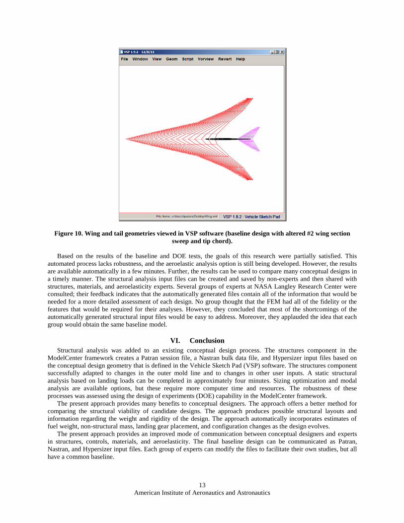
The initial DOE tests with the baseline design had many more failures than successes. The lower and upper
bounds on the design variables had to be adjusted. For example, if the #2 wing section sweep was too high or the #2
wing section tip chord was too small, then the volume that was needed to attach the fuselage to the wing was small
and oddly shaped. In that case, the logic that was used to create the wing box, main spars, and the kicker spar would
fail, and the Patran software terminated prematurely. Figure 10 shows an example of a geometry that would fail.
Here, the baseline design was altered so that the #2 wing section sweep was 77 deg and the tip chord was 26 ft. The
figure shows the GUI for the Vehicle Sketch Pad (VSP) software;12
each new concept is developed using VSP. The
wing is shown in red, and wing sections #1 through #4 are visible in the figure.
The results of the DOE test that is described in Table 1 were encouraging. Of the 50 cases, 41 cases executed in
both MSC/Patran and MSC/Nastran. Of the 41 completed runs, 19 were fully successful. Many of the other
automatically created models would run successfully if minor manual adjustments were made to the Nastran bulk
data file (e.g., finding and fixing a few missing connections between elements).
Following the DOE test, several of the cases were rerun in the ModelCenter framework. An additional 30 cases
were performed to test the Hypersizer optimization. Given a fully successful MSC/Nastran input file, the Hypersizer
optimization executed automatically without errors. Similarly, a fully successful Nastran input file can be
automatically adjusted to perform modal analysis. It is possible to add either Hypersizer optimization or modal
analysis to a large DOE test, but the normal practice is to run a single case and study the results in the Patran or
Hypersizer GUI.
Table 1. Design Variables for DOE Test
Variable Baseline Lower
bound
Upper
bound
Tail sweep, deg 58.1 50 60
Tail span, ft 9.9 8 12
#2 wing section tip chord, ft 31.8 31 32
#2 wing section sweep, deg 71 70 74
#2 wing section span, ft 9.9 7 10
#3 wing section sweep, deg 67.4 64 70
#3 wing section span, ft 9.3 8 10
#4 wing section sweep, deg 60 60 64
#4 wing section span, ft 10.3 8 12
American Institute of Aeronautics and Astronautics
12
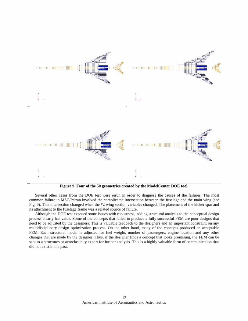
Figure 9. Four of the 50 geometries created by the ModelCenter DOE tool.
Several other cases from the DOE test were rerun in order to diagnose the causes of the failures. The most
common failure in MSC/Patran involved the complicated intersection between the fuselage and the main wing (see
Fig. 9). This intersection changed when the #2 wing section variables changed. The placement of the kicker spar and
its attachment to the fuselage frame was a related source of failure.
Although the DOE test exposed some issues with robustness, adding structural analysis to the conceptual design
process clearly has value. Some of the concepts that failed to produce a fully successful FEM are poor designs that
need to be adjusted by the designers. This is valuable feedback to the designers and an important constraint on any
multidisciplinary design optimization process. On the other hand, many of the concepts produced an acceptable
FEM. Each structural model is adjusted for fuel weight, number of passengers, engine location and any other
changes that are made by the designer. Thus, if the designer finds a concept that looks promising, the FEM can be
sent to a structures or aeroelasticity expert for further analysis. This is a highly valuable form of communication that
did not exist in the past.
American Institute of Aeronautics and Astronautics
13
Figure 10. Wing and tail geometries viewed in VSP software (baseline design with altered #2 wing section
sweep and tip chord).
Based on the results of the baseline and DOE tests, the goals of this research were partially satisfied. This
automated process lacks robustness, and the aeroelastic analysis option is still being developed. However, the results
are available automatically in a few minutes. Further, the results can be used to compare many conceptual designs in
a timely manner. The structural analysis input files can be created and saved by non-experts and then shared with
structures, materials, and aeroelasticity experts. Several groups of experts at NASA Langley Research Center were
consulted; their feedback indicates that the automatically generated files contain all of the information that would be
needed for a more detailed assessment of each design. No group thought that the FEM had all of the fidelity or the
features that would be required for their analyses. However, they concluded that most of the shortcomings of the
automatically generated structural input files would be easy to address. Moreover, they applauded the idea that each
group would obtain the same baseline model.
VI. Conclusion
Structural analysis was added to an existing conceptual design process. The structures component in the
ModelCenter framework creates a Patran session file, a Nastran bulk data file, and Hypersizer input files based on
the conceptual design geometry that is defined in the Vehicle Sketch Pad (VSP) software. The structures component
successfully adapted to changes in the outer mold line and to changes in other user inputs. A static structural
analysis based on landing loads can be completed in approximately four minutes. Sizing optimization and modal
analysis are available options, but these require more computer time and resources. The robustness of these
processes was assessed using the design of experiments (DOE) capability in the ModelCenter framework.
The present approach provides many benefits to conceptual designers. The approach offers a better method for
comparing the structural viability of candidate designs. The approach produces possible structural layouts and
information regarding the weight and rigidity of the design. The approach automatically incorporates estimates of
fuel weight, non-structural mass, landing gear placement, and configuration changes as the design evolves.
The present approach provides an improved mode of communication between conceptual designers and experts
in structures, controls, materials, and aeroelasticity. The final baseline design can be communicated as Patran,
Nastran, and Hypersizer input files. Each group of experts can modify the files to facilitate their own studies, but all
have a common baseline.

American Institute of Aeronautics and Astronautics
14
Acknowledgments
S. L. Padula would like to thank Tony Abby, Jim Leedom, and Mike Ripp of the MSC Software Corporation for
training and advice regarding the effective use of Patran and the Patran command language.
References 1Geiselhart, K. A., Ozoroski, L. P., Fenbert, J. W., Shields, E. W., and Li, W., “Integration of Multifidelity Multidisciplinary
Computer Codes for Design and Analysis of Supersonic Aircraft,” AIAA-2011-465, Presented at 49th AIAA Aerospace
Sciences Meeting, Orlando, Florida, Jan. 4-7, 2011. 2Ozoroski, L. P., Geiselhart, K. A., Padula, S. L., Li, W., Olson, E. D., Campbell, R. L., Shields, E. W., Berton, J. J., Gray, J.
S., Jones, S. M., Naiman, C. G., Seidel, J. A., Moore, K. T., Naylor, B. A., Townsend, S. , “Initial Multidisciplinary Design and
Analysis Framework,” NASA/TM-2010- 216711, June 2010.
3“ModelCenter, Design Integration Software (Version 10.0),” Phoenix Integration, Inc., Blacksburg, VA 24060, URL:
http://www.phoenix-int.com. 4“PATRAN Analysis Quick Reference Manual (Version 2008, r2),” MSC Software, Santa Ana, CA 92707, URL:
http://www.mscsoftware.com. 5Caffrey, J. P., and Lee, J. N., “MSC/NASTRAN Linear Static Analysis, User's Guide, Version 68,” The MacNeal-
Schwendler Corporation, Los Angeles, CA, 1996. 6 “NASTRAN Analysis Quick Reference Manual (Version 2008, r1),” MSC Software, Santa Ana, CA 92707. 7Alston, K., Doyle, S., Winter, T., Kim, H., Ragon, S., “High Fidelity Multidisciplinary Optimization (HFMDO),” AIAA-
2010-9319, Presented at the 13th AIAA/ISSMO Multidisciplinary Analysis Optimization Conference, Fort Worth, Texas, Sep.
13–15, 2010. 8“AML Basic Training Manual,” Technosoft Inc., Cincinnati, OH 45242, URL: http://www.technosoft.com. 9Stephenson, W., Veley, D., Hill, S., “Composite Vehicle Design Environment,” AIAA-2007-2371, Presented at the 48th
AIAA/ASME/ASCE/AHS/ASC Structures, Structural Dynamics, and Materials Conference, Honolulu, Hawaii, Apr. 23–26,
2007. 10Mukhopadhyay, V., Hsu, S., Mason, B., Hicks, M., Jones, W., Sleight, D., Chu, Julio, Spangler, J., Kamhawi, H., and Dahl,
J.: “Adaptive Modeling, Engineering Analysis and Design of Advanced Aerospace Vehicles,” AIAA-2006-2182, Presented at the
47th AIAA/ASME/ASCE/AHS/ASC Structures, Structural Dynamics, and Materials Conference 14th AIAA/ASME/AHS
Adaptive Structures Conference , Newport, Rhode Island, May 1–4, 2006. 11Collier, C., Yarrington, P., Pickenheim, M., and Bednarcyk, B., “An Approach to Preliminary Design and Analysis,”
Presented at the 48th AIAA/ASME/ASCE/AHS/ASC Structures, Structural Dynamics, and Materials Conference, Honolulu,
Hawaii, Apr. 23–26, 2007. 12Gloudemans, J., and McDonald, R., “Improved Geometry Modeling for High Fidelity Parametric Design,” Presented at the
48th AIAA Aerospace Sciences Meeting, Orlando, Florida, Jan. 4–7, 2010.