stress in asme - download.e-bookshelf.de · 5.6 stress in thick-wall spherical sections due to...
TRANSCRIPT

STRESS IN ASMEPRESSURE VESSELS,BOILERS, AND NUCLEARCOMPONENTS

Wiley-ASME Press Series List
Stress in ASME Pressure Vessels, Boilers, and NuclearComponents
Jawad October 2017
Robust Adaptive Control for Fractional-OrderSystems with Disturbance and Saturation
Shi November 2017
Robot Manipulator Redundancy Resolution Zhang October 2017
Combined Cooling, Heating, and Power Systems:Modeling, Optimization, and Operation
Shi August 2017
Applications of Mathematical Heat Transfer andFluid Flow Models in Engineering and Medicine
Dorfman February 2017
Bioprocessing Piping and Equipment Design:A Companion Guide for the ASME BPE Standard
Huitt December 2016
Nonlinear Regression Modeling for EngineeringApplications
Rhinehart September 2016
Fundamentals of Mechanical Vibrations Cai May 2016
Introduction to Dynamics and Control of MechanicalEngineering Systems
To March 2016

STRESS IN ASMEPRESSURE VESSELS,BOILERS, AND NUCLEARCOMPONENTS
Maan H. Jawad, Ph.D., P.E.Global Engineering & Technology, Inc.Camas, WA, USA

This edition first published 2018Copyright © 2018, The American Society of Mechanical Engineers (ASME), 2 Park Avenue,New York, NY, 10016, USA (www.asme.org).Published by John Wiley & Sons, Inc., Hoboken, New Jersey.
All rights reserved. No part of this publication may be reproduced, stored in a retrieval system, or transmitted, in anyform or by any means, electronic, mechanical, photocopying, recording or otherwise, except as permitted by law.Advice on how to obtain permission to reuse material from this title is available at http://www.wiley.com/go/permissions.
The right of Maan H. Jawad to be identified as the author of this work has been asserted in accordance with law.
Registered Office(s)John Wiley & Sons, Inc., 111 River Street, Hoboken, NJ 07030, USAJohn Wiley & Sons Ltd, The Atrium, Southern Gate, Chichester, West Sussex, PO19 8SQ, UK
Editorial OfficeThe Atrium, Southern Gate, Chichester, West Sussex, PO19 8SQ, UK
For details of our global editorial offices, customer services, and more information about Wiley products visit us atwww.wiley.com.
Wiley also publishes its books in a variety of electronic formats and by print-on-demand. Some content that appears instandard print versions of this book may not be available in other formats.
Limit of Liability/Disclaimer of WarrantyWhile the publisher and authors have used their best efforts in preparing this work, they make no representations orwarranties with respect to the accuracy or completeness of the contents of this work and specifically disclaim allwarranties, including without limitation any implied warranties of merchantability or fitness for a particular purpose.No warranty may be created or extended by sales representatives, written sales materials or promotional statementsfor this work. The fact that an organization, website, or product is referred to in this work as a citation and/or potentialsource of further information does not mean that the publisher and authors endorse the information or services theorganization, website, or product may provide or recommendations it may make. This work is sold with theunderstanding that the publisher is not engaged in rendering professional services. The advice and strategies containedherein may not be suitable for your situation. You should consult with a specialist where appropriate. Further,readers should be aware that websites listed in this work may have changed or disappeared between when this work waswritten and when it is read. Neither the publisher nor authors shall be liable for any loss of profit or any othercommercial damages, including but not limited to special, incidental, consequential, or other damages.
Library of Congress Cataloging-in-Publication Data
Names: Jawad, Maan H., author.Title: Stress in ASME pressure vessels, boilers and nuclear components / byMaan H. Jawad.
Description: First edition. | Hoboken, NJ : John Wiley & Sons, 2018. |Series: Wiley-ASME Press series | Includes bibliographical references and index. |
Identifiers: LCCN 2017018768 (print) | LCCN 2017036797 (ebook) | ISBN9781119259268 (pdf) | ISBN 9781119259275 (epub) | ISBN 9781119259282 (cloth)
Subjects: LCSH: Shells (Engineering) | Plates (Engineering) | Strains and stresses.Classification: LCC TA660.S5 (ebook) | LCC TA660.S5 J39 2017 (print) | DDC624.1/776–dc23
LC record available at https://lccn.loc.gov/2017018768
Cover design by WileyCover image: © I Verveer/Gettyimages
Set in 10 /12pt Times by SPi Global, Pondicherry, India
10 9 8 7 6 5 4 3 2 1

Contents
Series Preface ixAcknowledgment xi
1 Membrane Theory of Shells of Revolution 11.1 Introduction 11.2 Basic Equations of Equilibrium 11.3 Spherical and Ellipsoidal Shells Subjected to Axisymmetric Loads 61.4 Conical Shells 181.5 Cylindrical Shells 201.6 Cylindrical Shells with Elliptical Cross Section 221.7 Design of Shells of Revolution 23
Problems 23
2 Various Applications of the Membrane Theory 272.1 Analysis of Multicomponent Structures 272.2 Pressure–Area Method of Analysis 352.3 Deflection Due to Axisymmetric Loads 42
Problems 47
3 Analysis of Cylindrical Shells 513.1 Elastic Analysis of Thick-Wall Cylinders 513.2 Thick Cylinders with Off-center Bore 563.3 Stress Categories and Equivalent Stress Limits for Design and
Operating Conditions 573.4 Plastic Analysis of Thick Wall Cylinders 633.5 Creep Analysis of Thick-Wall Cylinders 653.6 Shell Equations in the ASME Code 693.7 Bending of Thin-Wall Cylinders Due to Axisymmetric Loads 71

3.8 Thermal Stress 893.9 Discontinuity Stresses 98
Problems 100
4 Buckling of Cylindrical Shells 1034.1 Introduction 1034.2 Basic Equations 1034.3 Lateral Pressure 1084.4 Lateral and End Pressure 1144.5 Axial Compression 1174.6 Design Equations 120
Problems 136
5 Stress in Shells of Revolution Due to Axisymmetric Loads 1415.1 Elastic Stress in Thick-Wall Spherical Sections Due to Pressure 1415.2 Spherical Shells in the ASME Code 1425.3 Stress in Ellipsoidal Shells Due to Pressure Using Elastic Analysis 1455.4 Ellipsoidal (Dished) Heads in the ASME Code 1465.5 Stress in Thick-Wall Spherical Sections Due to Pressure Using
Plastic Analysis 1505.6 Stress in Thick-Wall Spherical Sections Due to Pressure Using
Creep Analysis 1505.7 Bending of Shells of Revolution Due to Axisymmetric Loads 1515.8 Spherical Shells 1565.9 Conical Shells 165
Problems 174
6 Buckling of Shells of Revolution 1756.1 Elastic Buckling of Spherical Shells 1756.2 ASME Procedure for External Pressure 1796.3 Buckling of Stiffened Spherical Shells 1806.4 Ellipsoidal Shells 1816.5 Buckling of Conical Shells 1816.6 Various Shapes 184
Problems 184
7 Bending of Rectangular Plates 1877.1 Introduction 1877.2 Strain–Deflection Equations 1897.3 Stress–Deflection Expressions 1947.4 Force–Stress Expressions 1967.5 Governing Differential Equations 1977.6 Boundary Conditions 200
vi Contents
7.7 Double Series Solution of Simply Supported Plates 2047.8 Single Series Solution of Simply Supported Plates 2067.9 Rectangular Plates with Fixed Edges 2117.10 Plate Equations in the ASME Code 212
Problems 213
8 Bending of Circular Plates 2158.1 Plates Subjected to Uniform Loads in the θ-Direction 2158.2 Circular Plates in the ASME Code 2258.3 Plates on an Elastic Foundation 2278.4 Plates with Variable Boundary Conditions 2318.5 Design of Circular Plates 234
Problems 235
9 Approximate Analysis of Plates 2399.1 Introduction 2399.2 Yield Line Theory 2399.3 Further Application of the Yield Line Theory 2479.4 Design Concepts 253
Problems 255
10 Buckling of Plates 25910.1 Circular Plates 25910.2 Rectangular Plates 26310.3 Rectangular Plates with Various Boundary Conditions 27110.4 Finite Difference Equations for Buckling 27510.5 Other Aspects of Buckling 27710.6 Application of Buckling Expressions to Design Problems 279
Problems 282
11 Finite Element Analysis 28311.1 Definitions 28311.2 One-Dimensional Elements 28711.3 Linear Triangular Elements 29511.4 Axisymmetric Triangular Linear Elements 30211.5 Higher-Order Elements 30511.6 Nonlinear Analysis 307
Appendix A: Fourier Series 309A.1 General Equations 309A.2 Interval Change 313A.3 Half-Range Expansions 314A.4 Double Fourier Series 316
viiContents

Appendix B: Bessel Functions 319B.1 General Equations 319B.2 Some Bessel Identities 323B.3 Simplified Bessel Functions 325
Appendix C: Conversion Factors 327
References 329Answers to Selected Problems 333Index 335
viii Contents

Series Preface
The Wiley-ASME Press Series in Mechanical Engineering brings together two establishedleaders in mechanical engineering publishing to deliver high-quality, peer-reviewed bookscovering topics of current interest to engineers and researchers worldwide. The series publishesacross the breadth of mechanical engineering, comprising research, design and development,and manufacturing. It includes monographs, references, and course texts. Prospective topicsinclude emerging and advanced technologies in engineering design, computer-aided design,energy conversion and resources, heat transfer, manufacturing and processing, systems anddevices, renewable energy, robotics, and biotechnology.


Acknowledgment
The author would like to thank Mr. Donald Lange of the CIC Group and Bernard Wicklein andGrace Fechter of the Nooter Corporation in St. Louis, Missouri, for their support. Specialthanks are also given to Dr Chithranjan Nadarajah for providing the finite element analysisof the quadratic element in Chapter 11.

1Membrane Theory of Shellsof Revolution
1.1 Introduction
All thin cylindrical shells, spherical and ellipsoidal heads, and conical transition sections aregenerally analyzed and designed in accordance with the general membrane theory of shellsof revolution. These components include those designed in accordance with the ASME pres-sure vessel code (Section VIII), boiler code (Section I), and nuclear code (Section III). Someadjustments are sometimes made to the calculated thicknesses when the ratio of radius to thick-ness is small or when other factors such as creep or plastic analysis enter into consideration. Theeffect of these factors is discussed in later chapters, whereas assumptions and derivation of thebasic membrane equations needed to analyze shells of revolution due to various loading con-ditions are described here.
1.2 Basic Equations of Equilibrium
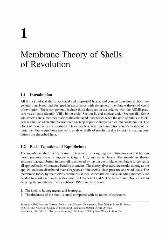
The membrane shell theory is used extensively in designing such structures as flat bottomtanks, pressure vessel components (Figure 1.1), and vessel heads. The membrane theoryassumes that equilibrium in the shell is achieved by having the in-plane membrane forces resistall applied loads without any bending moments. The theory gives accurate results as long as theapplied loads are distributed over a large area of the shell such as pressure and wind loads. Themembrane forces by themselves cannot resist local concentrated loads. Bending moments areneeded to resist such loads as discussed in Chapters 3 and 5. The basic assumptions made inderiving the membrane theory (Gibson 1965) are as follows:
1. The shell is homogeneous and isotropic.2. The thickness of the shell is small compared with its radius of curvature.
Stress in ASME Pressure Vessels, Boilers, and Nuclear Components, First Edition. Maan H. Jawad.© 2018, The American Society of Mechanical Engineers (ASME), 2 Park Avenue,New York, NY, 10016, USA (www.asme.org). Published 2018 by John Wiley & Sons, Inc.

3. The bending strains are negligible and only strains in the middle surface are considered.4. The deflection of the shell due to applied loads is small.
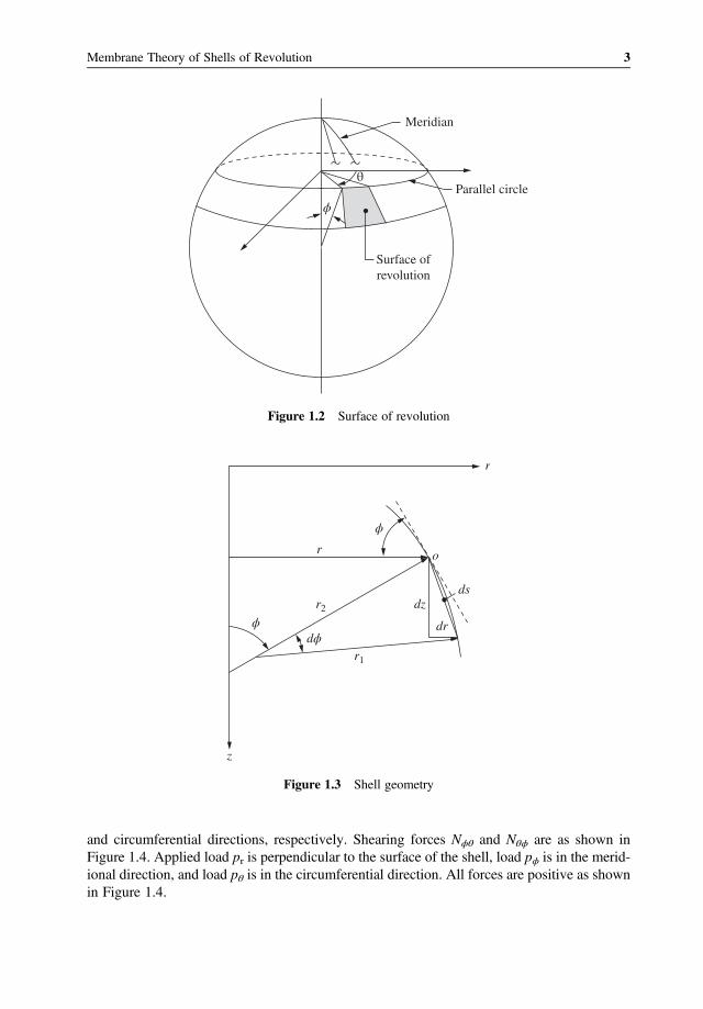
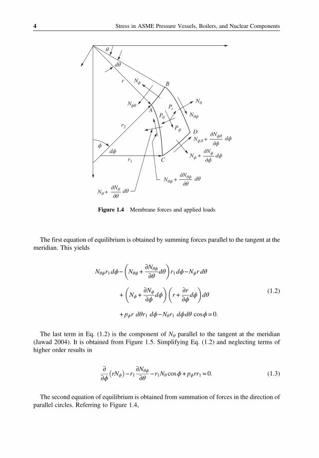
In order to derive the governing equations for the membrane theory of shells, we need todefine the shell geometry. The middle surface of a shell of constant thickness may be con-sidered a surface of revolution. A surface of revolution is obtained by rotating a plane curveabout an axis lying in the plane of the curve. This curve is called a meridian (Figure 1.2).Any point in the middle surface can be described first by specifying the meridian on whichit is located and second by specifying a quantity, called a parallel circle, that varies alongthe meridian and is constant on a circle around the axis of the shell. The meridian is definedby the angle θ and the parallel circle by ϕ as shown in Figure 1.2.Define r (Figure 1.3) as the radius from the axis of rotation to any given point o on the sur-
face; r1 as the radius from point o to the center of curvature of the meridian; and r2 as the radiusfrom the axis of revolution to point o, and it is perpendicular to the meridian. Then fromFigure 1.3,
r = r2 sinϕ, ds = r1dϕ, and dr = dscosϕ (1.1)
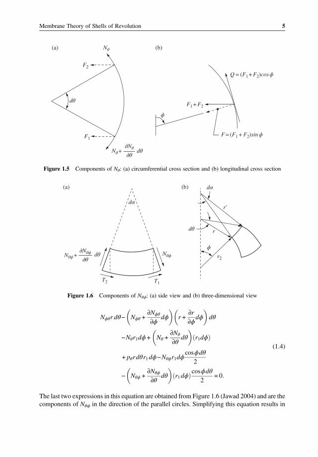
The interaction between the applied loads and resultant membrane forces is obtained fromstatics and is shown in Figure 1.4. Shell forcesNϕ andNθ are membrane forces in the meridional
Figure 1.1 Pressure vessels. Source: Courtesy of the Nooter Corporation, St. Louis, MO.
2 Stress in ASME Pressure Vessels, Boilers, and Nuclear Components
and circumferential directions, respectively. Shearing forces Nϕθ and Nθϕ are as shown inFigure 1.4. Applied load pr is perpendicular to the surface of the shell, load pϕ is in the merid-ional direction, and load pθ is in the circumferential direction. All forces are positive as shownin Figure 1.4.
Surface ofrevolution
Parallel circle
Meridian
θ
ϕ
Figure 1.2 Surface of revolution
r
r2
ϕdz
dϕ
o
ds
r1
z
dr
r
ϕ
Figure 1.3 Shell geometry
3Membrane Theory of Shells of Revolution
The first equation of equilibrium is obtained by summing forces parallel to the tangent at themeridian. This yields
Nθϕr1dϕ− Nθϕ +∂Nθϕ
∂θdθ r1dϕ−Nϕr dθ
+ Nϕ +∂Nϕ
∂ϕdϕ r +
∂r
∂ϕdϕ dθ
+ pϕr dθr1 dϕ−Nθr1 dϕdθ cosϕ= 0
(1.2)
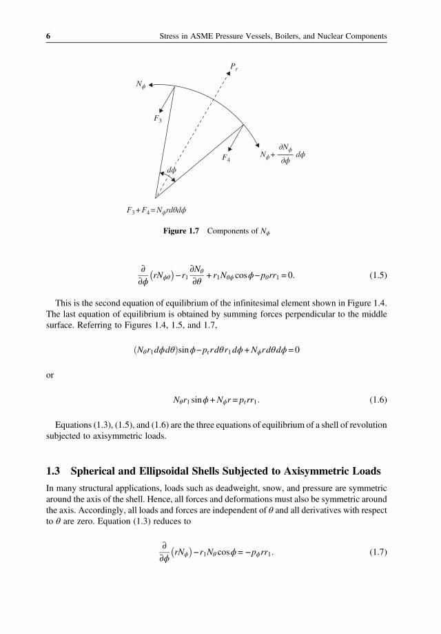
The last term in Eq. (1.2) is the component of Nθ parallel to the tangent at the meridian(Jawad 2004). It is obtained from Figure 1.5. Simplifying Eq. (1.2) and neglecting terms ofhigher order results in
∂
∂ϕrNϕ −r1
∂Nθϕ
∂θ−r1Nθ cosϕ+ pϕrr1 = 0 (1.3)
The second equation of equilibrium is obtained from summation of forces in the direction ofparallel circles. Referring to Figure 1.4,
Nθ + dθ∂Nθ∂θ
Nϕ + dϕ∂ϕ
∂Nϕ
Nθϕ + dθ∂θ
∂Nθϕ
Nθϕ
Nϕθ
Nϕ
Nθ
Nϕθ + dϕ∂ϕ
∂NϕθD
C
A
r2
r1
Br
Pr
Pθ
Pϕ
ϕdϕ
dθ
θ
Figure 1.4 Membrane forces and applied loads
4 Stress in ASME Pressure Vessels, Boilers, and Nuclear Components
Nϕθr dθ− Nϕθ +∂Nϕθ
∂ϕdϕ r +
∂r
∂ϕdϕ dθ
−Nθr1dϕ+ Nθ +∂Nθ
∂θdθ r1dϕ
+ pθrdθr1dϕ−Nθϕr1dϕcosϕdθ
2
− Nθϕ +∂Nθϕ
∂θdθ r1dϕ
cosϕdθ2
= 0
(1.4)
The last two expressions in this equation are obtained from Figure 1.6 (Jawad 2004) and are thecomponents of Nθϕ in the direction of the parallel circles. Simplifying this equation results in
F = (F1 + F2)sin ϕ
Q = (F1 + F2)cos ϕ
F1 + F2
F1
F2
Nθ + dθ∂θ
ϕ
∂Nθ
(b)(a) Nθ
dθ
Figure 1.5 Components of Nθ: (a) circumferential cross section and (b) longitudinal cross section
T2 T1
r′
r2
dα
dα
dθ r
(a) (b)
Nθϕ + Nθϕdθ∂θ
∂Nθϕϕ
Figure 1.6 Components of Nθϕ: (a) side view and (b) three-dimensional view
5Membrane Theory of Shells of Revolution
∂
∂ϕrNϕθ −r1
∂Nθ
∂θ+ r1Nθϕ cosϕ−pθrr1 = 0 (1.5)
This is the second equation of equilibrium of the infinitesimal element shown in Figure 1.4.The last equation of equilibrium is obtained by summing forces perpendicular to the middlesurface. Referring to Figures 1.4, 1.5, and 1.7,
Nθr1dϕdθ sinϕ−prrdθr1dϕ+Nϕrdθdϕ = 0
or
Nθr1 sinϕ +Nϕr = prrr1 (1.6)
Equations (1.3), (1.5), and (1.6) are the three equations of equilibrium of a shell of revolutionsubjected to axisymmetric loads.
1.3 Spherical and Ellipsoidal Shells Subjected to Axisymmetric Loads
In many structural applications, loads such as deadweight, snow, and pressure are symmetricaround the axis of the shell. Hence, all forces and deformations must also be symmetric aroundthe axis. Accordingly, all loads and forces are independent of θ and all derivatives with respectto θ are zero. Equation (1.3) reduces to
∂
∂ϕrNϕ −r1Nθ cosϕ = −pϕrr1 (1.7)
F3 + F4 = Nϕrdθdϕ
F3
Pr
F4Nϕ +
Nϕ
dϕ∂ϕ
∂Nϕ
dϕ
Figure 1.7 Components of Nϕ
6 Stress in ASME Pressure Vessels, Boilers, and Nuclear Components

Equation (1.5) becomes
∂
∂ϕrNθϕ + r1Nθϕ cosϕ= pθrr1 (1.8)
In this equation, we let the cross shears Nϕθ =Nθϕ in order to maintain equilibrium.Equation (1.6) can be expressed as
Nθ
r2+Nϕ
r1= pr (1.9)
Equation (1.8) describes a torsion condition in the shell. This condition produces deform-ations around the axis of the shell. However, the deformation around the axis is zero due toaxisymmetric loads. Hence, we must set Nθϕ = pθ = 0 and we disregard Eq. (1.8) from furtherconsideration.Substituting Eq. (1.9) into Eq. (1.7) gives
Nϕ =1
r2sin2ϕ
r1r2 pr cosϕ−pϕ sinϕ sinϕdϕ +C (1.10)
The constant of integration C in Eq. (1.10) is additionally used to take into consideration theeffect of any additional applied loads that cannot be defined by pr and pϕ such as weight ofcontents.Equations (1.9) and (1.10) are the two governing equations for designing double-curvature
shells under membrane action.
1.3.1 Spherical Shells Subjected to Internal Pressure
For spherical shells under axisymmetric loads, the differential equations can be simplified byletting r1 = r2 = R. Equations (1.9) and (1.10) become
Nϕ +Nθ = prR (1.11)
and
Nϕ =R
sin2ϕpr cosϕ−pϕ sinϕ sinϕdϕ +C (1.12)
These two expressions form the basis for developing solutions to various loading conditionsin spherical shells. For any loading condition, expressions for pr and pϕ are first determined andthen the previous equations are solved for Nϕ and Nθ.For a spherical shell under internal pressure, pr = P and pϕ = 0. Hence, from Eqs. (1.11)
and (1.12),
Nϕ =Nθ =PR
2=PD
4(1.13)
7Membrane Theory of Shells of Revolution

where D is the diameter of the sphere. The required thickness is obtained from
t =Nϕ
S=Nθ
S(1.14)
where S is the allowable stress.Equation (1.14) is accurate for design purposes as long asR/t ≥ 10. If R/t < 10, then thick shell
equations, described in Chapter 3, must be used.
1.3.2 Spherical Shells under Various Loading Conditions
The following examples illustrate the use of Eqs. (1.11) and (1.12) for determining forces inspherical segments subjected to various loading conditions.
Example 1.1A storage tank roof with thickness t has a dead load of γ psf. Find the expressions forNϕ andNθ.
SolutionFrom Figure 1.8a and Eq. (1.12),
pr = −γ cosϕ and pϕ = γ sinϕ
Nϕ =R
sin2ϕ−γcos2ϕ−γsin2ϕ sinϕdϕ +C
Nϕ =R
sin2ϕγ cosϕ +C (1)
As ϕ approaches zero, the denominator in Eq. (1) approaches zero. Accordingly, we must letthe bracketed term in the numerator equal zero. This yields C = –γ. Equation (1) becomes
Nϕ =−Rγ 1−cosϕ
sin2ϕ(2)
The convergence of Eq. (2) as ϕ approaches zero can be checked by l’Hopital’s rule. Thus,
Nϕϕ = 0
=−Rγsinϕ
2sinϕcosϕ ϕ = 0
=−γR
2
Equation (2) can be written as
Nϕ =−γR
1 + cosϕ(3)
8 Stress in ASME Pressure Vessels, Boilers, and Nuclear Components

From Eq. (1.11), Nθ is given by
Nθ = γR1
1 + cosϕ−cosϕ (4)
A plot of Nϕ and Nθ for various values of ϕ is shown in Figure 1.8b, showing that for angles ϕgreater than 52 , the hoop force, Nθ, changes from compression to tension and special attentionis needed in using the appropriate allowable stress values.
Example 1.2Find the forces in a spherical head due to a vertical load Po applied at an angle ϕ = ϕo as shownin Figure 1.9a.
γ
ϕR
(a)
–0.6
–0.4
–0.2
0
0.2
0.4
0.6
20
N
Nθ
Nϕ
γR
40 60 80 20 40 60 80
0.8
–0.6
–0.4
–0.2
0
0.2
0.4
0.6
0.8
N
γR
ϕ ϕ
(b)
Figure 1.8 Membrane forces in a head due to deadweight: (a) dead load and (b) force patterns
9Membrane Theory of Shells of Revolution
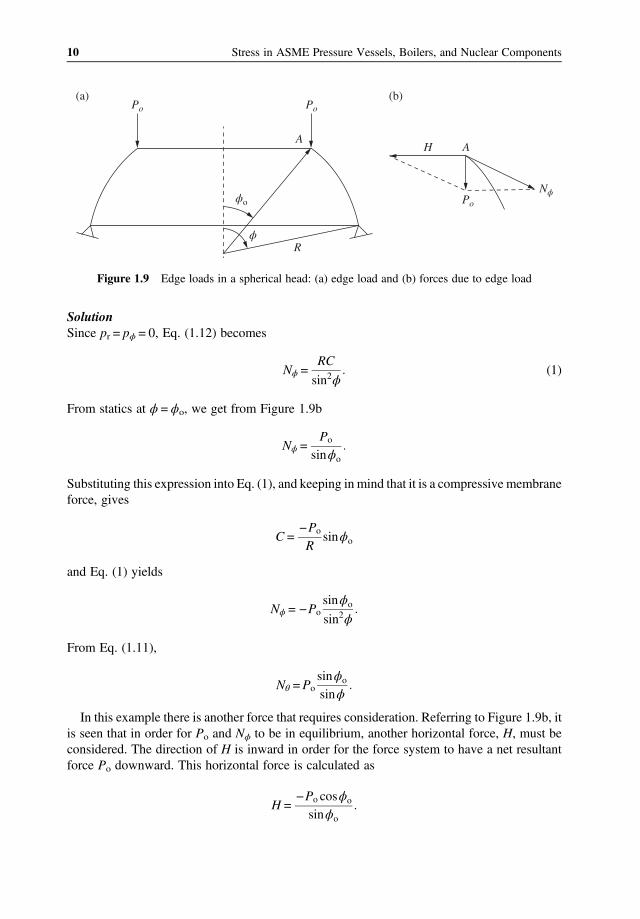
SolutionSince pr = pϕ = 0, Eq. (1.12) becomes
Nϕ =RC
sin2ϕ(1)
From statics at ϕ = ϕo, we get from Figure 1.9b
Nϕ =Po
sinϕo
Substituting this expression into Eq. (1), and keeping in mind that it is a compressive membraneforce, gives
C =−Po
Rsinϕo
and Eq. (1) yields
Nϕ = −Posinϕo
sin2ϕ
From Eq. (1.11),
Nθ =Posinϕo
sinϕ
In this example there is another force that requires consideration. Referring to Figure 1.9b, itis seen that in order for Po and Nϕ to be in equilibrium, another horizontal force, H, must beconsidered. The direction of H is inward in order for the force system to have a net resultantforce Po downward. This horizontal force is calculated as
H =−Po cosϕo
sinϕo
Po Po
A
(a) (b)
AH
Po
R
ϕo
Nϕ
ϕ
Figure 1.9 Edge loads in a spherical head: (a) edge load and (b) forces due to edge load
10 Stress in ASME Pressure Vessels, Boilers, and Nuclear Components
A compression ring is needed at the inner edge in order to contain force H.The required area, A, of the ring is given by
A=H Rsinϕo
σ
where σ is the allowable compressive stress of the ring.
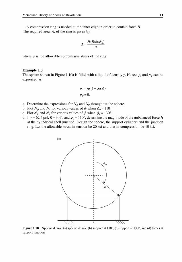
Example 1.3The sphere shown in Figure 1.10a is filled with a liquid of density γ. Hence, pr and pϕ can beexpressed as
pr = γR 1−cosϕ
pϕ = 0
a. Determine the expressions for Nϕ and Nθ throughout the sphere.b. Plot Nϕ and Nθ for various values of ϕ when ϕo = 110 .c. Plot Nϕ and Nθ for various values of ϕ when ϕo = 130 .d. If γ = 62.4 pcf, R = 30 ft, and ϕo = 110 , determine the magnitude of the unbalanced force H
at the cylindrical shell junction. Design the sphere, the support cylinder, and the junctionring. Let the allowable stress in tension be 20 ksi and that in compression be 10 ksi.
R
(a)
ϕo
Figure 1.10 Spherical tank: (a) spherical tank, (b) support at 110 , (c) support at 130 , and (d) forces atsupport junction
11Membrane Theory of Shells of Revolution

(b)
(c)
110°
130°
.03
.11
.17
.1074
.8624.89
.97 .9
.61
.481.23
.83
.39
.10
1.0 1.0
Nϕ
Nϕ Nθ
γR2
Nθ
γR2
.03
.11
.17
.22
0@120° .92
.97 .9
.73
1.86
1.50
.83
.39
.10
1.0 1.0
Nϕ
Nϕ Nθ
γR2
Nθ
γR2
130°
130°
(d)
A
C
B R′
0.1074γR2
0.1009γR2
0.0367γR2
0.7095γR2
0.8104γR2
0.8624γR2
0.2950γR2
Figure 1.10 (Continued)
12 Stress in ASME Pressure Vessels, Boilers, and Nuclear Components
Solutiona. From Eq. (1.12), we obtain
Nϕ =γR2
sin2ϕ
12sin2ϕ+
13cos3ϕ+C (1)
As ϕ approaches zero, the denominator approaches zero. Hence, the bracketed term in thenumerator must be set to zero. This gives C = −1/3 and Eq. (1) becomes
Nϕ =γR2
6sin2ϕ3sin2ϕ + 2cos3ϕ−2 (2)
The corresponding Nθ from Eq. (1.11) is
Nθ = γR2 12−cosϕ−
1
3sin2ϕcos3ϕ−1 (3)
As ϕ approaches π, we need to evaluate Eq. (1) at that point to ensure a finite solution.Again the denominator approaches zero and the bracketed term in the numerator must be setto zero. This gives C = 1/3 and Eq. (1) becomes
Nϕ =γR2
6sin2ϕ3sin2ϕ+ 2cos3ϕ + 2 (4)
The corresponding Nθ from Eq. (1.11) is
Nθ = γR2 12−cosϕ−
1
3sin2ϕcos3ϕ + 1 (5)
Equations (2) and (3) are applicable between 0 < ϕ < ϕo, and Eqs. (4) and (5) are applicablebetween ϕo < ϕ < π.
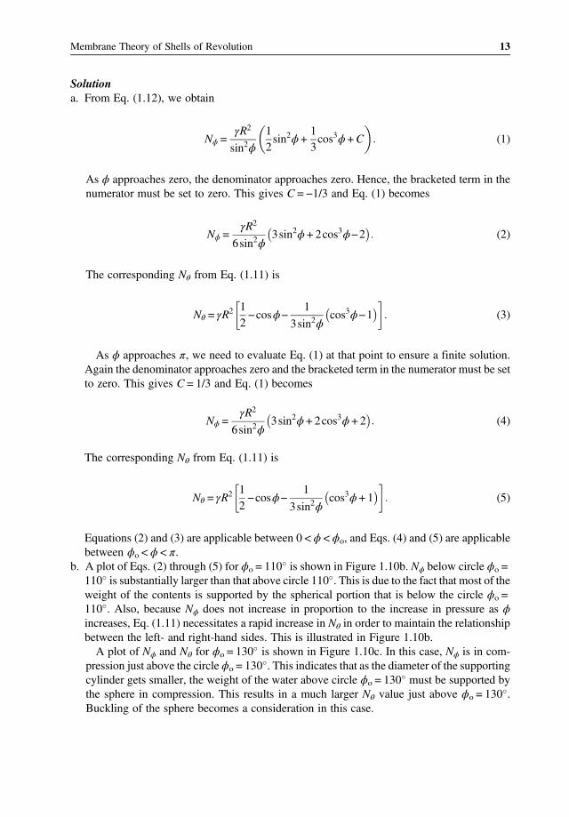
b. A plot of Eqs. (2) through (5) for ϕo = 110 is shown in Figure 1.10b. Nϕ below circle ϕo =110 is substantially larger than that above circle 110 . This is due to the fact that most of theweight of the contents is supported by the spherical portion that is below the circle ϕo =110 . Also, because Nϕ does not increase in proportion to the increase in pressure as ϕincreases, Eq. (1.11) necessitates a rapid increase in Nθ in order to maintain the relationshipbetween the left- and right-hand sides. This is illustrated in Figure 1.10b.A plot of Nϕ and Nθ for ϕo = 130 is shown in Figure 1.10c. In this case, Nϕ is in com-
pression just above the circle ϕo = 130 . This indicates that as the diameter of the supportingcylinder gets smaller, the weight of the water above circle ϕo = 130 must be supported bythe sphere in compression. This results in a much larger Nθ value just above ϕo = 130 .Buckling of the sphere becomes a consideration in this case.
13Membrane Theory of Shells of Revolution

c. From Figure 1.10b for ϕo = 110 , the maximum force in the sphere is Nθ = 1.23γR2. Therequired thickness of the sphere is
t =1 23 62 4 30 2 12
20,000
= 0 29 inch
A free-body diagram of the spherical and cylindrical junction at ϕo = 110 is shown inFigure 1.10d. The values ofNϕ at points A and B are obtained from Eqs. (2) and (4), respect-ively. The vertical and horizontal components of these forces are shown at points A and B inFigure 1.10d. The unbalanced vertical forces result in a downward force at point C of mag-nitude 0.7095γR2. The total force on the cylinder is (0.7095γR2)(2π)(R)(sin (180 − 110)).This total force is equal to the total weight of the contents in the sphere given by (4/3)(πR3)γ. The required thickness of the cylinder is
t =0 7095 62 4 30 2 12
10,000
= 0 33 inch
Summation of horizontal forces at points A and B results in a compressive force of mag-nitude 0.2583γR2. The needed area of compression ring at the cylinder to sphere junction is
A=Hr
σ=0 2583 × 62 4 × 302 30sin70
10,000
= 40 89 inch2
This area is furnished by a large ring added to the sphere or an increase in the thickness ofthe sphere at the junction.
1.3.3 ASME Code Equations for Spherical Shells underVarious Loading Conditions
Loading conditions such as those shown in Examples 1.1 through 1.3 are not specificallycovered by equations in the boiler and pressure vessel codes. However, they are addressedin paragraph PG-16.1 of Section I, paragraph U-2(g) of Section VIII-1, and paragraph 4.1.1of Section VIII-2 using special analysis.In the nuclear code, paragraph NC-3932.2 of Section NC and ND-3932.2 of Section ND
provide equations for calculating forces at specific locations in a shell due to loading conditionssimilar to those shown in Examples 1.1 through 1.5. This procedure is discussed further inChapter 2.
14 Stress in ASME Pressure Vessels, Boilers, and Nuclear Components

1.3.4 Ellipsoidal Shells under Internal Pressure
Ellipsoidal heads of all sizes and shapes are used in the ASME code as end closure for pressurecomponents. The general configuration is shown in Figure 1.11.Small-size heads are formed by using dyes shaped to a true ellipse. However, large diameter
heads formed from plate segments are in the shapes of spherical and torispherical geometriesthat simulate ellipses as shown in Figures 1.12 and 1.13. Figure 1.12 shows an ASME
Nϕ Nθ+
+ +
–
ϕr2
r1 b
a
Figure 1.11 Ellipsoidal head under internal pressure
D/2h = 2 : 1
h
D
(a)
h.17D
.9D
D
(b)
Figure 1.12 2 : 1 elliptical head: (a) exact configuration and (b) approximate configuration
15Membrane Theory of Shells of Revolution
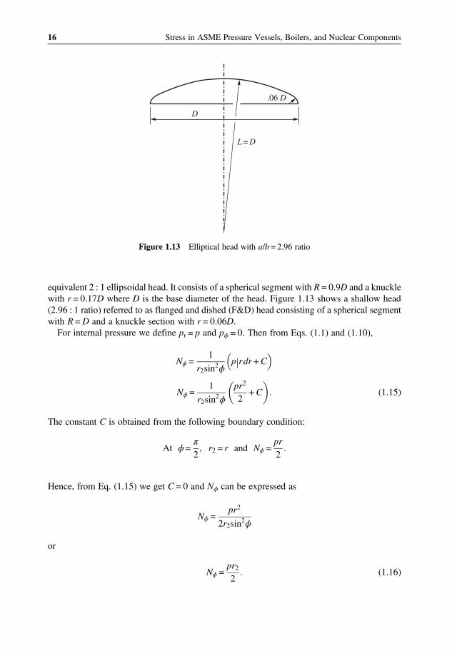
equivalent 2 : 1 ellipsoidal head. It consists of a spherical segment with R = 0.9D and a knucklewith r = 0.17D where D is the base diameter of the head. Figure 1.13 shows a shallow head(2.96 : 1 ratio) referred to as flanged and dished (F&D) head consisting of a spherical segmentwith R =D and a knuckle section with r = 0.06D.For internal pressure we define pr = p and pϕ = 0. Then from Eqs. (1.1) and (1.10),
Nϕ =1
r2sin2ϕ
p rdr +C
Nϕ =1
r2sin2ϕ
pr2
2+C (1.15)
The constant C is obtained from the following boundary condition:
At ϕ=π
2, r2 = r and Nϕ =
pr
2
Hence, from Eq. (1.15) we get C = 0 and Nϕ can be expressed as
Nϕ =pr2
2r2sin2ϕ
or
Nϕ =pr22
(1.16)
.06 D
L = D
D
Figure 1.13 Elliptical head with a/b = 2.96 ratio
16 Stress in ASME Pressure Vessels, Boilers, and Nuclear Components