stress concentration factors due to typical geometric
TRANSCRIPT

Paper ID #6755
Stress concentration factors due to typical geometric discontinuities for shaftdesign by numerical simulation
Dr. Xiaobin Le P.E., Wentworth Institute of Technology
Associate Professor Xiaobin Le, PhD, P.Eng, specialization in Computer Aided Design, Mechanical De-sign, Finite Element Analysis, Fatigue Design and Reliability, Department of Mechanical Engineeringand Technology, College of Engineering and Technology, Wentworth Institute of Technology, Boston,MA 02115, Phone:617-989-4223, Email: [email protected]
Mr. Zelong Le, Wentworth Institute of Technology
Currently a Sophomore in Electrical Engineering (BSEE) in the department of Electrical Engineering andTechnology, College of Engineering and Technology, Wentworth Institute of Technology, Boston, MA,02115. Email: [email protected]
c©American Society for Engineering Education, 2013
Page 23.1091.1

Stress concentration factors due to typical geometric discontinuities for shaft design by numerical simulation
Abstract
Stress concentrations are caused by geometric discontinuities. Step shoulders with fillets, key seats and retaining-ring grooves in shafts are typical geometric discontinuities. In lots of mechanical component designs textbooks, the stress concentration factors for the step shoulders with different fillets on shafts are fully explored and presented by sets of stress concentration factor curves. The preliminary stress concentration factors of retaining ring grooves are also provided. Key seats are typical features of shafts. They are a typical type of geometric discontinuities, but no related stress concentration factor curves of key seats are listed and shown in textbooks. No full set of preliminary stress concentration factors of key seats for shaft design is presented. In this paper, the stress concentration phenomena of profile key seats and sled runner key seats will be systematically explored by FEA (Finite Element Analysis). A set of stress concentration factor curves /tables and equations on key seats will be presented. The preliminary stress concentration factors of both profile and sled runner key seats under bending, torsion and axial loading for shaft designs are presented in this paper.
1. Introduction
The geometric discontinuities on shaft are unavoidable due to some required functions. But geometric discontinuities will cause significant stress concentrations. Step shoulders with fillets, retaining-ring grooves and key seats in shafts are the typical geometric discontinuities. In lots of mechanical component design textbooks[1,2,3], the stress concentration factors for the step shoulders with different fillets on shafts are fully explored and presented by sets of stress concentration factor curves. The preliminary stress concentration factors of retaining ring grooves are also provided. Key seats are typical geometric discontinuous features of shafts, but no related stress concentration factor curves or tables of key seats are provided. No consistent full set of preliminary stress concentration factors due to key seats for shaft design are presented [1, 2, 3].
The key is the simplest machinery component placed at the interface between a shaft and the hub of a power-transmitting element for the purpose of transmitting torque. The most common type of keys is parallel keys. The parallel key is installed in an axial groove machined into the shaft and the hub, called key seat. Two types of key seats are most frequently used: profile and sled runner. The profile key seat is milled into the shaft, using an end mill having a diameter equal to the width of the key. The resulting groove is a flat-bottomed and has sharp, square corners at its ends. The sled runner key seat is produced by a circular milling cutter
Page 23.1091.2
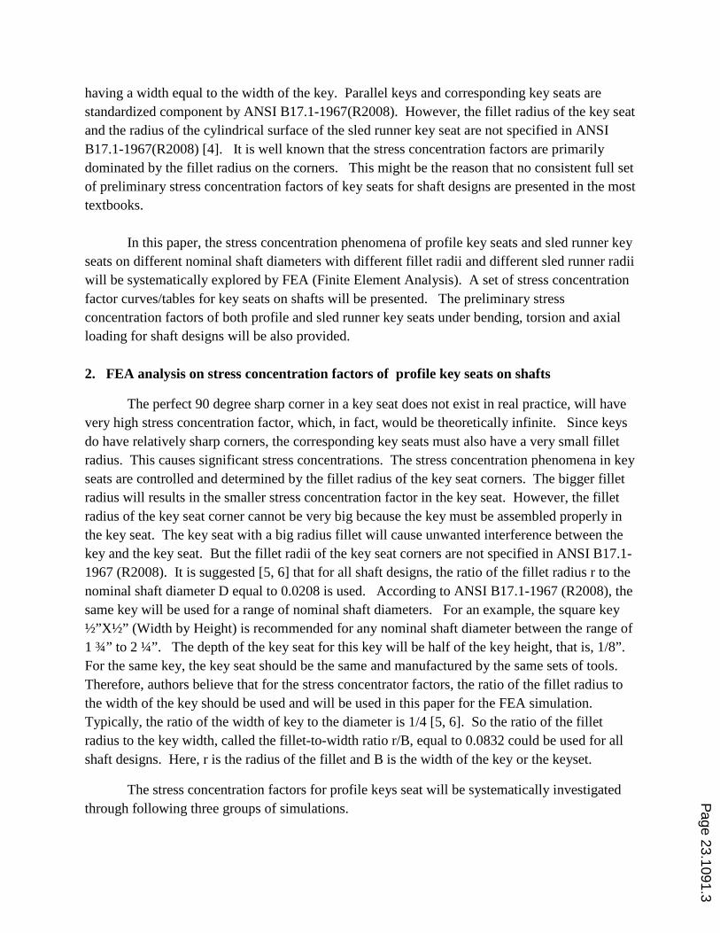
having a width equal to the width of the key. Parallel keys and corresponding key seats are standardized component by ANSI B17.1-1967(R2008). However, the fillet radius of the key seat and the radius of the cylindrical surface of the sled runner key seat are not specified in ANSI B17.1-1967(R2008) [4]. It is well known that the stress concentration factors are primarily dominated by the fillet radius on the corners. This might be the reason that no consistent full set of preliminary stress concentration factors of key seats for shaft designs are presented in the most textbooks.
In this paper, the stress concentration phenomena of profile key seats and sled runner key
seats on different nominal shaft diameters with different fillet radii and different sled runner radii will be systematically explored by FEA (Finite Element Analysis). A set of stress concentration factor curves/tables for key seats on shafts will be presented. The preliminary stress concentration factors of both profile and sled runner key seats under bending, torsion and axial loading for shaft designs will be also provided. 2. FEA analysis on stress concentration factors of profile key seats on shafts
The perfect 90 degree sharp corner in a key seat does not exist in real practice, will have very high stress concentration factor, which, in fact, would be theoretically infinite. Since keys do have relatively sharp corners, the corresponding key seats must also have a very small fillet radius. This causes significant stress concentrations. The stress concentration phenomena in key seats are controlled and determined by the fillet radius of the key seat corners. The bigger fillet radius will results in the smaller stress concentration factor in the key seat. However, the fillet radius of the key seat corner cannot be very big because the key must be assembled properly in the key seat. The key seat with a big radius fillet will cause unwanted interference between the key and the key seat. But the fillet radii of the key seat corners are not specified in ANSI B17.1-1967 (R2008). It is suggested [5, 6] that for all shaft designs, the ratio of the fillet radius r to the nominal shaft diameter D equal to 0.0208 is used. According to ANSI B17.1-1967 (R2008), the same key will be used for a range of nominal shaft diameters. For an example, the square key ½”X½” (Width by Height) is recommended for any nominal shaft diameter between the range of 1 ¾” to 2 ¼”. The depth of the key seat for this key will be half of the key height, that is, 1/8”. For the same key, the key seat should be the same and manufactured by the same sets of tools. Therefore, authors believe that for the stress concentrator factors, the ratio of the fillet radius to the width of the key should be used and will be used in this paper for the FEA simulation. Typically, the ratio of the width of key to the diameter is 1/4 [5, 6]. So the ratio of the fillet radius to the key width, called the fillet-to-width ratio r/B, equal to 0.0832 could be used for all shaft designs. Here, r is the radius of the fillet and B is the width of the key or the keyset.
The stress concentration factors for profile keys seat will be systematically investigated through following three groups of simulations.
Page 23.1091.3

(1) The stress distributions in the profile key seat with the r/B= 0.0832 under torsion, bending and axial loading will be investigated in order to find the maximum shear or normal stress’s locations on the key seat.
(2) The profile key seats with the r/B=0.0832 on the corresponding shaft diameter for every standardized key will be investigated through FEA to explore the effects of shaft nominal diameters on stress concentration factors under bending, torsion and axial loading.
(3) The shaft models with the same shaft diameter and the same key seat having different r/B will be numerically simulated to investigate the effects of the r/B on the stress concentration factors.
2.1 The stress distributions in a profile key with the r/B=0.0832
In order to explore the typical stress distributions and stress concentration phenomena on
a profile key seat, following settings are used: (1) the effective key seat length will be four times of the key width, (2) The length of the shaft will be the five times of the effective key seat length; (3) the r/B=0.0832, (4) the nominal shaft diameter is 1 1/16”; (5) the key size will be ¼”X ¼” according to ANSI B17.1-1967(R2008), and (6) one end of the shaft is fixed and the loading (torsion, bending and axial tension) is applied on the other end. The (1), (2) and (6) settings will be used for all simulations discussed in this paper.
The FEA simulation will be conducted through SolidWorks simulation. The meshing
information is shown in Figure 1. The much fine meshing is created on the fillet surfaces and the side surfaces of the profile key seat through the “Applied meshing control” [7]. At least five elements will be created along the arc fillet surfaces for all simulations of this paper. For an example, the fillet radius in this case is equal to: 0.0832 X ¼”=0.0208” and the arc length in the fillet section is 0.0327”. The element size for the fillet surface will be 0.0065” in this simulation. The FEA analysis model of this simulation has total 104384 elements as shown in Figure 1. The “p-adaptive” method [7] with the convergence criteria that the total strain energy change is less than 2% is used to check the convergence of the simulations.
The arrow point in following figures is the maximum shear or normal stress location. The Von Mises distribution of the profile key seat under torsion is shown in Figure 2, which clearly shows that maximum Von Mises occurs at the middle of the longitudinal fillet section on the bottom of the profile key seat. This maximum Von Mises stress is mainly contributed by the shear stress on the fillet surface due to the torsion. The shear stress distribution of the profile key seat under torsion is shown in Figure 3. In Figure 3, the maximum shear stress happens at the longitudinal fillet surface on the bottom of the profile key seat. The maximum and minimum normal stresses, that is, the first principal stress and the third principal stress on the profile key seat under torsion is shown in Figure 4. In Figure 4, the maximum and minimum normal stress occurs on the semi-cylindrical sections of both ends of the profile key seat. These observations are the same as the observations described by Peterson’ works [5, 6]. This maximum shear stress
Page 23.1091.4
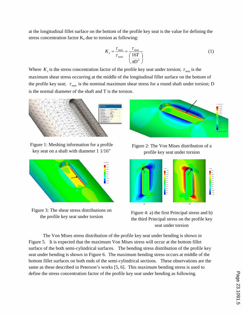
at the longitudinal fillet surface on the bottom of the profile key seat is the value for defining the stress concentration factor Ks due to torsion as following:
(1) 16
3
maxmax
==
DT
Knom
s
π
τττ
Where sK is the stress concentration factor of the profile key seat under torsion; maxτ is the maximum shear stress occurring at the middle of the longitudinal fillet surface on the bottom of the profile key seat; nomτ is the nominal maximum shear stress for a round shaft under torsion; D is the normal diameter of the shaft and T is the torsion.
Figure 1: Meshing information for a profile key seat on a shaft with diameter 1 1/16”
Figure 2: The Von Mises distribution of a profile key seat under torsion
Figure 3: The shear stress distributions on the profile key seat under torsion
Figure 4: a) the first Principal stress and b) the third Principal stress on the profile key
seat under torsion
The Von Mises stress distribution of the profile key seat under bending is shown in Figure 5. It is expected that the maximum Von Mises stress will occur at the bottom fillet surface of the both semi-cylindrical surfaces. The bending stress distribution of the profile key seat under bending is shown in Figure 6. The maximum bending stress occurs at middle of the bottom fillet surfaces on both ends of the semi-cylindrical sections. These observations are the same as these described in Peterson’s works [5, 6]. This maximum bending stress is used to define the stress concentration factor of the profile key seat under bending as following.
Page 23.1091.5

(2) 32
3
maxmax
==
DM
Knom
TB
π
σσσ
Where TBK is the stress concentration factor of the profile key seat under bending; maxσ is the maximum bending stress occurring at the middle of the bottom fillet surfaces on both ends of semi-cylindrical sections; nomσ is the nominal maximum bending stress for a round shaft under bending; D is the normal diameter of the shaft; and M is the bending moment.
Figure 5: The Von Mises distribution of the
profile key seat under bending
Figure 6: The bending stress distribution of
the profile key seat under bending
The Von Mises stress and normal axial stress distributions of the profile key seat under axial loading are shown in Figures 7 and8. The maximum Von Mises and axial normal stress occur at the middle of the bottom fillet surface on both end semi-cylindrical sections, which are similar to these under bending. This maximum axial normal stress is used to define the stress concentration factor of the profile key under axial loading as shown in equation (3).
Figure 7: The Von Misese distribution of the
profile key seat under axial loading
Figure 8: The axial normal stress of the
profile key seat under axial loading
(3) 4
2
maxmax
==
DF
Knom
TA
π
σσσ
Where TAK is the stress concentration factor of the profile key seat under axial loading; maxσ is the maximum axial normal stress occurring at the middle of the bottom fillet surface on both P
age 23.1091.6

ends of semi-cylindrical surfaces; nomσ is the nominal axial normal stress for a round shaft under axial loading; D is the normal diameter of the shaft, and F is the axial loading.
2.2 The stress concentration factors of different keys with the r/B= 0.0832
16 different keys are specified and recommended for corresponding shaft diameters with the range of 5/16” to 11” in ANSI B17-1-1967 (R2008) [4]. Each key will be corresponded with a small range of the shaft diameters. For an example, the same square key 5/16” X 5/16” (width X height) is recommended for any shaft diameter between 1 ¼” and 1 3/8”. A set of FEA analysis on the stress concentration factors for the profile key seat with a fixed r/B=0.0832, but with different diameters, have been conducted. In this set of simulations, for each key, the shaft diameter is the average diameter of the recommended shaft diameter range. For example, for the square key 5/16” X 5/16”, the shaft diameter in the simulation will be 1 15/16”, which is the average value of the suggested diameter range of 1 ¼” to 1 3/8”. The simulation results are listed and shown in Table 1.
According to Table 1, the stress concentration factors of the profile key seat under torsion, bending or axial loading on different shaft diameter with the same r/B=0.0832 are almost independent of the shaft diameters when the shaft diameters are in accordance with the recommended key size versus shaft diameter on ANSI B17-1-1967 (R2008) [4]. The average stress concentration factors listed in Table 1 can be used for the preliminary stress concentration factors, that is, the preliminary stress concentration factors of the profile key seat under torsion, bending and axial loading are 2.26, 2.20 and 2.81, respectively.
Table 1 the stress concentration factors of the profile key seats with the r/B= 0.0832 Shaft
diameter Key size
(Width X Height) Depth of key seat
Fillet radius KTB (Bending)
Ks (Torsion)
KTA (Axial)
3/8” 3/32” X 3/32” 3/64” 0.0078” 2.202 2.232 2.830 ½” 1/8” X 1/8” 1/16” 0.0104” 2.150 2.234 2.830
11/16” 3/16” X 3/16” 3/32” 0.0156” 2.158 2.235 2.847 1 1/16” ¼” X ¼” 1/8” 0.0208” 2.280 2.244 2.778 1 5/16” 5/16” X 5/16” 5/32” 0.0260” 2.267 2.228 2.797 1 9/16” 3/8” X 3/8” 3/16” 0.0312” 2.312 2.246 2.824
2” ½” X ½” ¼” 0.0416” 2.249 2.045 2.713 2 ½” 5/8” X 5/8” 5/16” 0.0520” 2.207 2.240 2.833
3” ¾” X 3/4” 3/8” 0.0624” 2.196 2.243 2.818 3 ½” 7/8” X 7/8” 7/16” 0.0728” 2.339 2.267 2.874
4” 1” X 1” ½” 0.0832” 2.273 2.239 2.807 5” 1 ¼” X1 ¼” 5/8” 0.1040” 2.273 2.268 2.871 6” 1 ½” X 1 ½” ¾” 0.1248” 2.279 2.261 2.878 7” 1 ¾” X1 ½” ¾” 0.1456” 2.320 2.146 2.829
8 ¼” 2” X 1 ½” ¾” 0.1664” 2.292 2.040 2.703 10” 2 ½” X 1 ¾” ¾” 0.2080” 2.320 2.005 2.723
Average 2.26 2.20 2.81
Page 23.1091.7
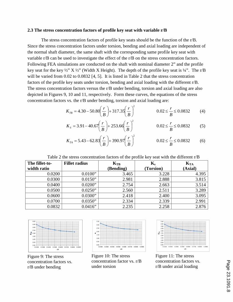
2.3 The stress concentration factors of profile key seat with variable r/B
The stress concentration factors of profile key seats should be the function of the r/B. Since the stress concentration factors under torsion, bending and axial loading are independent of the normal shaft diameter, the same shaft with the corresponding same profile key seat with variable r/B can be used to investigate the effect of the r/B on the stress concentration factors. Following FEA simulations are conducted on the shaft with nominal diameter 2” and the profile key seat for the key ½” X ½” (Width X Height). The depth of the profile key seat is ¼”. The r/B will be varied from 0.02 to 0.0832 [4, 5]. It is listed in Table 2 that the stress concentration factors of the profile key seats under torsion, bending and axial loading with the different r/B. The stress concentration factors versus the r/B under bending, torsion and axial loading are also depicted in Figures 9, 10 and 11, respectively. Form these curves, the equations of the stress concentration factors vs. the r/B under bending, torsion and axial loading are:
(4) 0832.00.02 35.31780.5030.42
≤≤
+
−=
Br
Br
BrKTB
(5) 0832.00.02 66.25367.4091.32
≤≤
+
−=
Br
Br
BrKS
(6) 0832.00.02 97.39083.6243.5
2
≤≤
+
−=
Br
Br
BrKTA
Table 2 the stress concentration factors of the profile key seat with the different r/B The fillet-to-width ratio
Fillet radius KTB (Bending)
Ks (Torsion)
KTA (Axial)
0.0200 0.0100” 3.465 3.228 4.395 0.0300 0.0150” 2.981 2.888 3.815 0.0400 0.0200” 2.754 2.663 3.514 0.0500 0.0250” 2.560 2.511 3.289 0.0600 0.0300” 2.418 2.400 3.095 0.0700 0.0350” 2.334 2.339 2.991 0.0832 0.0416” 2.235 2.258 2.876
Figure 9: The stress concentration factors vs. r/B under bending
Figure 10: The stress concentration factor vs. r/B under torsion
Figure 11: The stress concentration factors vs. r/B under axial loading
Page 23.1091.8
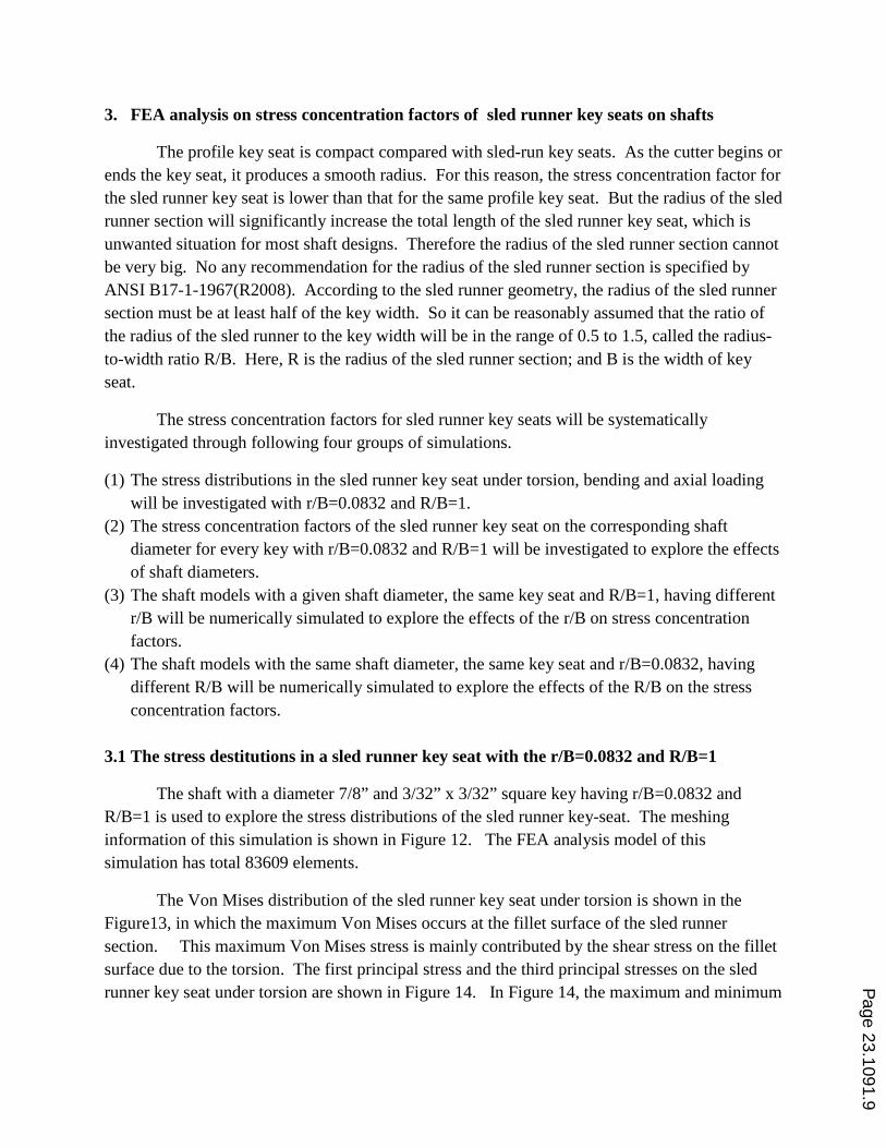
3. FEA analysis on stress concentration factors of sled runner key seats on shafts
The profile key seat is compact compared with sled-run key seats. As the cutter begins or ends the key seat, it produces a smooth radius. For this reason, the stress concentration factor for the sled runner key seat is lower than that for the same profile key seat. But the radius of the sled runner section will significantly increase the total length of the sled runner key seat, which is unwanted situation for most shaft designs. Therefore the radius of the sled runner section cannot be very big. No any recommendation for the radius of the sled runner section is specified by ANSI B17-1-1967(R2008). According to the sled runner geometry, the radius of the sled runner section must be at least half of the key width. So it can be reasonably assumed that the ratio of the radius of the sled runner to the key width will be in the range of 0.5 to 1.5, called the radius-to-width ratio R/B. Here, R is the radius of the sled runner section; and B is the width of key seat.
The stress concentration factors for sled runner key seats will be systematically investigated through following four groups of simulations.
(1) The stress distributions in the sled runner key seat under torsion, bending and axial loading will be investigated with r/B=0.0832 and R/B=1.
(2) The stress concentration factors of the sled runner key seat on the corresponding shaft diameter for every key with r/B=0.0832 and R/B=1 will be investigated to explore the effects of shaft diameters.
(3) The shaft models with a given shaft diameter, the same key seat and R/B=1, having different r/B will be numerically simulated to explore the effects of the r/B on stress concentration factors.
(4) The shaft models with the same shaft diameter, the same key seat and r/B=0.0832, having different R/B will be numerically simulated to explore the effects of the R/B on the stress concentration factors.
3.1 The stress destitutions in a sled runner key seat with the r/B=0.0832 and R/B=1
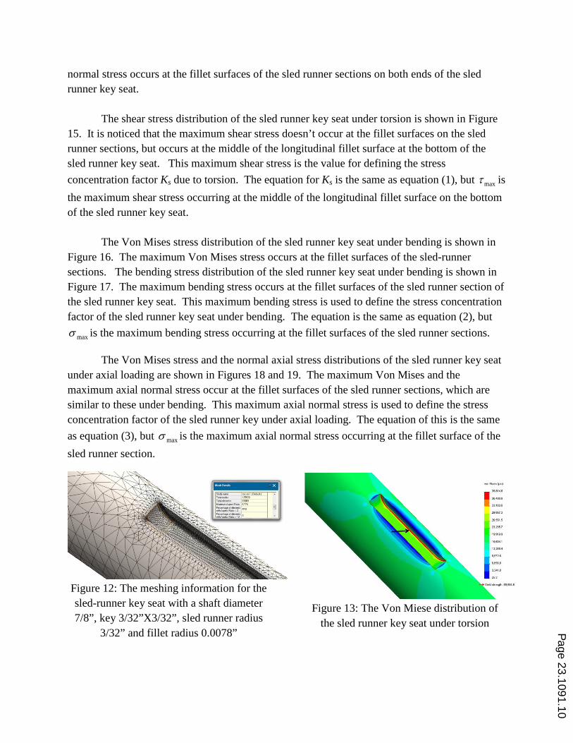
The shaft with a diameter 7/8” and 3/32” x 3/32” square key having r/B=0.0832 and R/B=1 is used to explore the stress distributions of the sled runner key-seat. The meshing information of this simulation is shown in Figure 12. The FEA analysis model of this simulation has total 83609 elements.
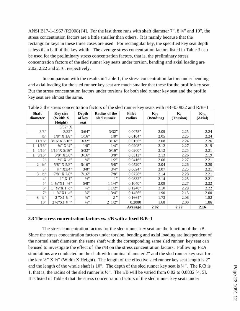
The Von Mises distribution of the sled runner key seat under torsion is shown in the Figure13, in which the maximum Von Mises occurs at the fillet surface of the sled runner section. This maximum Von Mises stress is mainly contributed by the shear stress on the fillet surface due to the torsion. The first principal stress and the third principal stresses on the sled runner key seat under torsion are shown in Figure 14. In Figure 14, the maximum and minimum P
age 23.1091.9
normal stress occurs at the fillet surfaces of the sled runner sections on both ends of the sled runner key seat.
The shear stress distribution of the sled runner key seat under torsion is shown in Figure
15. It is noticed that the maximum shear stress doesn’t occur at the fillet surfaces on the sled runner sections, but occurs at the middle of the longitudinal fillet surface at the bottom of the sled runner key seat. This maximum shear stress is the value for defining the stress concentration factor Ks due to torsion. The equation for Ks is the same as equation (1), but maxτ is the maximum shear stress occurring at the middle of the longitudinal fillet surface on the bottom of the sled runner key seat.
The Von Mises stress distribution of the sled runner key seat under bending is shown in
Figure 16. The maximum Von Mises stress occurs at the fillet surfaces of the sled-runner sections. The bending stress distribution of the sled runner key seat under bending is shown in Figure 17. The maximum bending stress occurs at the fillet surfaces of the sled runner section of the sled runner key seat. This maximum bending stress is used to define the stress concentration factor of the sled runner key seat under bending. The equation is the same as equation (2), but
maxσ is the maximum bending stress occurring at the fillet surfaces of the sled runner sections.
The Von Mises stress and the normal axial stress distributions of the sled runner key seat under axial loading are shown in Figures 18 and 19. The maximum Von Mises and the maximum axial normal stress occur at the fillet surfaces of the sled runner sections, which are similar to these under bending. This maximum axial normal stress is used to define the stress concentration factor of the sled runner key under axial loading. The equation of this is the same as equation (3), but maxσ is the maximum axial normal stress occurring at the fillet surface of the sled runner section.
Figure 12: The meshing information for the sled-runner key seat with a shaft diameter 7/8”, key 3/32”X3/32”, sled runner radius
3/32” and fillet radius 0.0078”
Figure 13: The Von Miese distribution of
the sled runner key seat under torsion
Page 23.1091.10

Figure 14: a) the first and b) the third
principal stresses of the sled runner key seat under torsion
Figure 15: The shear stress distribution of
the sled runner key seat under torsion
Figure 16: The Von Mises distribution of the
sled runner key seat under bending
Figure 17: The maximum bending stress of
the sled runner key seat under bending
Figure 18: The Von Mises stress of the sled runner key seat under axial loading
Figure 19: The maximal normal stress of the
sled runner key seat under axial loading
3.2 The stress concentration factors of different keys for sled profile key seat with r/B=0.0832 and R/B=1
A set of FEA simulations on the stress concentration factors for the sled runner key seat with different diameters, the same r/B=0.0832 and the same R/B=1 have been conducted.
The stress concentration factors of the sled runner key seat under torsion, bending or axial loading on different shaft diameter with r/B=0.0832 and R/B=1 are listed in Table 3. The stress concentration factors of the sled runner key seat under torsion, bending or axial loading on different shaft diameter with r/B=0.0832 and R/B=1 are independent of the shaft diameters when the shaft diameters are in accordance with the recommended key size versus shaft diameter on
Page 23.1091.11
ANSI B17-1-1967 (R2008) [4]. For the last three runs with shaft diameter 7”, 8 ¼” and 10”, the stress concentration factors are a little smaller than others. It is mainly because that the rectangular keys in these three cases are used. For rectangular key, the specified key seat depth is less than half of the key width. The average stress concentration factors listed in Table 3 can be used for the preliminary stress concentration factors, that is, the preliminary stress concentration factors of the sled runner key seats under torsion, bending and axial loading are 2.02, 2.22 and 2.16, respectively.
In comparison with the results in Table 1, the stress concentration factors under bending and axial loading for the sled runner key seat are much smaller that these for the profile key seat. But the stress concentration factors under torsions for both sled runner key seat and the profile key seat are almost the same.
Table 3 the stress concentration factors of the sled runner key seats with r/B=0.0832 and R/B=1 Shaft
diameter Key size (Width X Height)
Depth of key seat
Radius of the sled runner
Fillet radius
KTB (Bending)
Ks (Torsion)
KTA (Axial)
3/8” 3/32” X
3/32” 3/64” 3/32” 0.0078” 2.09 2.25 2.24 ½” 1/8” X 1/8” 1/16” 1/8” 0.0104” 2.05 2.25 2.24
11/16” 3/16”X 3/16” 3/32” 3/16” 0.0156” 2.08 2.24 2.26 1 1/16” ¼” X ¼” 1/8” 1/4” 0.0208” 2.12 2.27 2.19 1 5/16” 5/16”X 5/16” 5/32” 5/16” 0.0260” 2.12 2.25 2.21 1 9/16” 3/8” X3/8” 3/16” 3/8” 0.0312” 2.13 2.26 2.19
2” ½” X ½” ¼” 1/2” 0.0416” 2.06 2.27 2.21 2 ½” 5/8” X 5/8” 5/16” 5/8” 0.0520” 2.04 2.26 2.20
3” ¾” X3/4” 3/8” 3/4” 0.0624” 2.07 2.25 2.21 3 ½” 7/8” X 7/8” 7/16” 7/8” 0.0728” 2.14 2.28 2.21
4” 1” X 1” ½” 1” 0.0832” 2.14 2.25 2.21 5” 1 ¼”X1 ¼” 5/8” 1 1/4” 0.1040” 2.09 2.27 2.22 6” 1 ½”X 1 ½” ¾” 1 1/2” 0.1248” 2.10 2.29 2.22 7” 1 ¾”X1 ½” ¾” 1 3/4” 0.1456” 1.90 2.15 2.00
8 ¼” 2 ”X1 ¾”” ¾” 2 ” 0.1664” 1.73 2.06 1.82 10” 2 ½”X1 ¾”” ¾” 2 1/2” 0.2080 1.68 2.00 1.86
Average 2.02 2.22 2.16
3.3 The stress concentration factors vs. r/B with a fixed R/B=1
The stress concentration factors for the sled runner key seat are the function of the r/B. Since the stress concentration factors under torsion, bending and axial loading are independent of the normal shaft diameter, the same shaft with the corresponding same sled runner key seat can be used to investigate the effect of the r/B on the stress concentration factors. Following FEA simulations are conducted on the shaft with nominal diameter 2” and the sled runner key seat for the key ½” X ½” (Width X Height). The length of the effective sled runner key seat length is 2” and the length of the whole shaft is 10”. The depth of the sled runner key seat is ¼”. The R/B is 1, that is, the radius of the sled runner is ½”. The r/B will be varied from 0.02 to 0.0832 [4, 5]. It is listed in Table 4 that the stress concentration factors of the sled runner key seats under
Page 23.1091.12
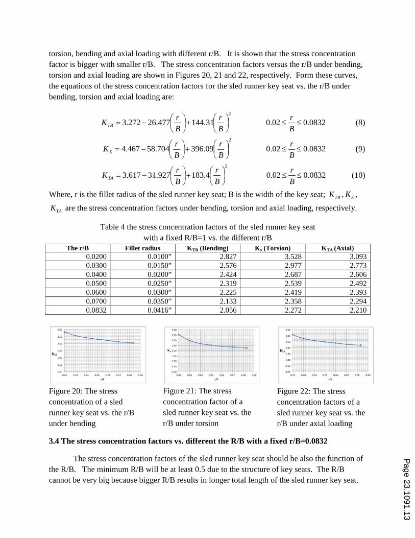
torsion, bending and axial loading with different r/B. It is shown that the stress concentration factor is bigger with smaller r/B. The stress concentration factors versus the r/B under bending, torsion and axial loading are shown in Figures 20, 21 and 22, respectively. Form these curves, the equations of the stress concentration factors for the sled runner key seat vs. the r/B under bending, torsion and axial loading are:
(8) 0832.00.02 31.144477.26272.32
≤≤
+
−=
Br
Br
BrKTB
(9) 0832.00.02 09.396704.58467.42
≤≤
+
−=
Br
Br
BrKS
(10) 0832.00.02 4.183927.31617.32
≤≤
+
−=
Br
Br
BrKTA
Where, r is the fillet radius of the sled runner key seat; B is the width of the key seat; TBK , SK ,
TAK are the stress concentration factors under bending, torsion and axial loading, respectively.
Table 4 the stress concentration factors of the sled runner key seat with a fixed R/B=1 vs. the different r/B
The r/B Fillet radius KTB (Bending) Ks (Torsion) KTA (Axial) 0.0200 0.0100” 2.827 3.528 3.093 0.0300 0.0150” 2.576 2.977 2.773 0.0400 0.0200” 2.424 2.687 2.606 0.0500 0.0250” 2.319 2.539 2.492 0.0600 0.0300” 2.225 2.419 2.393 0.0700 0.0350” 2.133 2.358 2.294 0.0832 0.0416” 2.056 2.272 2.210
Figure 20: The stress concentration of a sled runner key seat vs. the r/B under bending
Figure 21: The stress concentration factor of a sled runner key seat vs. the r/B under torsion
Figure 22: The stress concentration factors of a sled runner key seat vs. the r/B under axial loading
3.4 The stress concentration factors vs. different the R/B with a fixed r/B=0.0832
The stress concentration factors of the sled runner key seat should be also the function of the R/B. The minimum R/B will be at least 0.5 due to the structure of key seats. The R/B cannot be very big because bigger R/B results in longer total length of the sled runner key seat.
Page 23.1091.13

The FEA models with the R/B range of 0.5 to 1.5 are used to investigate its effects on the stress concentration factors of the sled runner key seat under bending, torsion and axial loading.
The stress concentration factors of the sled runner key seats versus the R/B under bending, torsion and axial loading are listed in Table 5 and also depicted in Figures 23, 24 and 25. Table 5 indicates: (1) the stress concentration factors of the sled runner key seat under torsion are independent of the R/B; and (2) the stress concentration factors of the sled runner key seats under bending and axial loading are smaller when the R/B is bigger. By comparison of the results in Table 1 with the results in Table 5, the sled runner key seat has much lower stress concentration factors under bending and axial loading. Based on Table 5, Figures 23 and 25, the stress concentration factors of sled runner key seat under bending and axial loading vs. the R/B are:
5.10.5 6199.0 0854.25273.32
≤≤
+
−=
BR
BR
BRKTB (11)
5.10.5 7073.0 3592.28692.32
≤≤
+
−=
BR
BR
BRKTA (12)
Where, R is the radius of the sled runner section of the sled runner key seat; B is the width of the key or the key seat; TBK is the stress concentration factors of the sled runner key seat under bending; TAK is the stress concentration factors of the sled runner key seat under axial loading.
Table 5 the stress concentration factors of the sled runner key seat with a fixed r/B=0.0832 vs. the different R/B
The R/B Radius of the sled runner KTB (Bending) Ks (Torsion) KTA (Axial) 0.500 1/2 2.661 2.462 2.889 0.625 5/8 2.445 2.300 2.651 0.750 3/4 2.306 2.267 2.489 0.875 7/8 2.165 2.272 2.334 1.000 1 2.056 2.272 2.210 1.125 1 1/8 1.986 2.274 2.133 1.250 1 1/4 1.904 2.283 2.042 1.375 1 3/8 1.833 2.276 1.964 1.500 1 1/2 1.781 2.271 1.907
Figure 23: The stress concentration of a sled runner key seat vs. the R/B under bending
Figure 24: The stress concentration of a sled runner key seat vs. the R/B under torsion
Figure 25: The stress concentration of a sled runner key seat vs. the R/B under axial loading
Page 23.1091.14
The stress concentration factors for sled runner key seats under bending and axial loading are the functions of both the r/B and the R/B. Based on the data shown in Table 4 and Table 5, the stress concentration factors of the sled runner key seat under bending and the axial loading can be calculated by following equations (13) and (14), respectively.
5.10.5 ,0832.00.02
31.144477.26272.3 6199.0 0854.25273.322
≤≤≤≤
+
−×
+
−=
BR
Br
Br
Br
BR
BRKTB
(13)
5.10.5 ,0832.00.02
31.144477.26272.3 7073.0 3592.28692.322
≤≤≤≤
+
−×
+
−=
BR
Br
Br
Br
BR
BRKTA
(14)
Where, R is the radius of the sled runner section; r is the fillet radius, B is the width of the key seat; TBK is the stress concentration factors of the sled runner key seat under bending; TAK is the stress concentration factors of the sled runner key seat under axial loading.
4. Summary
Key seats for parallel keys are typical features of shafts. Parallel keys and corresponding key seats are standardized by ANSI B71-1-1967(R2008). The nominal shaft diameter vs. the standard key size is also recommended by ANSI B71-1-1967(2008). The common key seats for parallel key are the profile key seat and the sled runner key seat. This paper has systematically investigated the stress concentration factors of profile key seats and sled runner key seats under bending, torsion and axial loading. The corresponding tables, curves and equations are presented in sections 2 and 3 of this paper. Followings are the summary.
For profile key-seats: (1) The stress concentration factors under bending, torsion and axial loading can be treated to be
independent of the shaft diameters, and are mainly the function of the r/B. (2) The maximum bending stress of the profile key seat under bending occurs at the middle of
the bottom fillet surfaces on both end semi-cylindrical sections. (3) The maximum shear stress of the profile key seat under torsion occurs at the middle of the
longitudinal fillet surface on the bottom of the profile key seat. (4) The maximum axial normal stress of the profile key seat under axial loading occurs at the
middle of the bottom fillet surface on both end semi-cylindrical sections. (5) The stress concentration factors vs. the r/B under bending, torsion and axial loading can be
calculated by Equations (4), (5) and (6), respectively.
Page 23.1091.15
(6) The preliminary stress concentration factors of profile key seat under bending, torsion and axial loading can be the values with the r/B= 0.0832. They are: 26.2=TBK ; 20.2=SK ; and
81.2=TAK
For sled runner key-seats: (1) The stress concentration factors under bending, torsion and axial loading can be treated to be
independent of the shaft diameters, and are mainly the function of the r/B or/and the R/B. (2) The maximum shear stress of the sled runner key seat under torsion occurs at the middle of
the longitudinal fillet surfaces at the bottom of the sled runner key seat. (3) The maximum bending stress of the sled runner key seats under bending occurs at the fillet
surfaces of the sled runner sections. (4) The maximum axial normal stress of sled runner key seat under axial loading occurs at the
fillet surfaces of the sled runner sections. (5) The stress concentration factor of sled runner key seat under torsion is independent of the
R/B and is only the function of the r/B. The stress concentration factor of the sled runner key seat under torsions vs. the r/B is described in Equation (9).
(6) The stress concentration factors of sled runner key seats under bending and the axial loading are the function of both the r/B and the R/B. The stress concentration factors will have higher values with a smaller r/B and a smaller R/B. The stress concentration factors vs. the r/B and the R/B under bending and axial loading can be calculated by Equations (13) and (14), respectively.
(7) The preliminary stress concentration factors of sled runner key seat under bending, torsion and axial loading can be the values with the r/B= 0.0832 and the R/B=1. They are:
02.2=TBK ; 20.2=SK ; and 16.2=TAK . (8) The sled runner key seat on a shaft will have significant lower stress concentration factors
under bending and axial loading than these with the profile key seat. But the stress concentration factors under torsion for both profile and sled runner key seats are almost the same.
5. References
[1]. Robert L. Mott, “Machine Elements in mechanical design”, Fourth Edition, 2004, Person Prentice Hall [2]. Richard G. Budynas and J. Keith Nisbeet, “Shigley’s mechanical Engineering Design”, Ninth Edition, 2011,
McGraw Hill Higher Education [3]. Robert L. Norton, “Machine design: An integrated approach”, 1996, Prentice Hall Inc [4]. Oberg, Erik; Jones, Franklin D.; Horton, Holbrook L.; Ryffel, Henry H., “Machinery's Handbook & Guide to
Machinery's Handbook” , 28th edition, 2008, Industrial Press, [5]. Walter D. Pilkey and Deborah F. Pilke, “Peterson’s Stress Concentration factors”, 2008, John Wiley and Sons,
Inc. [6]. Walter D. Pilkey, “Formulas for stress, strain and structural matrices”, Second Edition, 2005, John Wiley and
Sons, Inc. [7]. Paul Hurowski, “Engineering analysis with SolidWorks Simulation 2012”, SDC publications, 2012
Page 23.1091.16