effects of geometric stress concentration in the design of
TRANSCRIPT
International Journal of Engineering Research and Technology. ISSN 0974-3154, Volume 13, Number 9 (2020), pp. 2255-2268
© International Research Publication House. https://dx.doi.org/10.37624/IJERT/13.9.2020.2255-2268
2255
Effects of Geometric Stress Concentration in the Design of Thick Compound
Cylinders- A Review
Naftali Kiplagat*, Leonard Masu1, and Patrick Nziu2
Department of Mechanical Engineering
Vaal University of Technology, Vanderbijlpark Campus, Private Bag X021, Vanderbijlpark- 1911, Andries Potgieter Blvd, South Africa.
ORCIDs: 0000-0003-1203-645X (Naftali Kiplagat), 0000-0002-8544-6321 (Prof. LM Masu), 0000-0002-5899-0700 (PK Nziu)
Abstract
This paper reviews some of the critical considerations that are
important during the design of high-pressure vessels. These
critical considerations include Stress Concentration Factors
(SCF), measurement of stress distribution, and geometric
design parameters affecting stress concentration in the design
of pressure vessels with a specific focus on thick compound
cylinders. Further, the motivation of this study is to analyze
stress concentration that occurs after the provision of cross
bores in pressure vessels. Stress analysis can be performed
using experimental, analytical, and numerical techniques.
Hence, the study concluded that there is no known analysis
carried out on the effects of cross bores on thick compound
cylinders using Finite Element Analysis (FEA). Thus, there is
need for understanding the effects of optimization of geometric
parameters of cross bore size, shape, location, obliquity and
thickness ratio, in the design of thick compound cylinders.
Keywords: Stress concentration, Stress Distribution, Stress
Concentration Factors, High-Pressure Vessels, Thick
Compound cylinders, Finite Element Analysis.
1 INTRODUCTION
Pressure vessels can be used in nuclear plants, thermal power
plants, chemical industries as well as process industries, space
depths, and supply of fluids in industries (Kharat and Kulkarni,
2013). Besides, pressure vessels are often equipped with
openings so that nozzles, handholds, and manholes can be
accommodated. These holes vary in size and can range from
big openings having flanges to small drain nozzles. These holes
are often referred to as cross bore(Makulsawatudom et al.,
2004). The cross bore is a critical catalyst of a flaw in a pressure
vessel because of the high-stress concentrations that arise in the
presence of the cross bore (Masu and Craggs, 1992).
Consequently, the cross bore will cause geometric
discontinuities that alter stress distribution and create regions
that are called areas of stress concentrations. Thus, the
geometrical configuration severely affects the high-stress
concentration of the cross bore where it intersects with the main
bore. The stress concentration due to static stresses is
determined using a factor that is known as the Stress
Concentration Factor (SCF)(Nziu and Masu, 2019a).
2 MEASUREMENT OF STRESS DISTRIBUTION
Stress analysis of important elements that are subjected to
various loading conditions has been conducted by researchers
for the safe design of the element. Therefore, the analysis of
stress distribution in pressure vessels can be determined
through experimental, analytical, or numerical techniques.
Experimental techniques obtain results directly (Kharat and
Kulkarni, 2013) while stresses distribution in a structure having
boundary conditions which are dislodgments and/or forces on
the boundary can be evaluated by either analytical or numerical
technique(Dharmin et al., 2012).
Experimental methods use various techniques like a grid,
coating moiré, photoelasticity, grid, brittle, electrical strain
gauge measurements, and other experimental solutions.
Electrical strain gauges are the most deployed and acceptable
for strain measurement and stress analysis (Nagpal et al., 2012)
In the experimental method, prototype is largely used for
experimental testing, however, pressure vessel prototype
analysis is relatively expensive and consumes time (Masu,
1998).
Analytical techniques also are known as closed-form analytical
methods that solve boundary value problems analytically using
equations constituted based on the plastic or elastic behavior of
the material subjected to forces (Dharmin et al., 2012).
Analytical solutions can also be obtained from simple geometry
(Nagpal et al., 2012) and, using various mathematical methods
such as complex function theory, such as complex variable
approach, Laurent series expansion, conformal mapping,
boundary application, etc. and some integral transforms like
Laplace, Mellin, Fourier, Hanckel, Eigenfunction expansion,
etc.. Over time, computer software packages like Maple and
Matlab have been used to answer the simultaneous equations
generated by these analytical techniques.
Finally, numerical techniques obtain approximate solutions for
boundary-value problems by the adoption of numerical
methods like finite difference technique, finite element method,
finite volume method, boundary element method, and meshless
method(Nagpal et al., 2012). Each of these techniques is
deployed for various applications. Hence, to solve
discontinuous or moving boundaries problems, Mesh Free
method has been used (Dharmin et al., 2012) while the
Boundary Element Method has been deployed for modeling
problems with rapidly changing stresses. The Finite Element
Method has been deployed by many researchers to compare the

International Journal of Engineering Research and Technology. ISSN 0974-3154, Volume 13, Number 9 (2020), pp. 2255-2268
© International Research Publication House. https://dx.doi.org/10.37624/IJERT/13.9.2020.2255-2268
2256
analytical and experimental results and therefore the method
can be used for simulation (Kharat and Kulkarni, 2013).
In the finite element method, elements that are small pieces
having simple shapes are obtained from the structural model to
be analyzed. Using Finite Element Analysis (FEA) the program
develops an equation that governs the behavior of each element
while considering the connectivity of the elements to other
elements by nodes. Therefore, these developed equations are
used to relate the unknown items like displacements in stress
analysis, to the known material properties, loads, and restraints.
The package goes ahead and constitutes equations into a large
set of simultaneous algebraic equations into their thousands and
also to their millions. The program solves the simultaneous
equations to obtain the stress distribution for the whole model.
Recently, with the introduction of computer software
programming, advanced software based on the FEA theory has
been developed. This software includes COSMOL, ADINA,
NASTRAN, ABAQUS, LUSAS, etc, which have been
commonly used in performing stress analysis. Researchers and
designers deploy software depending on the type of stress
analysis, the type of elements to be analyzed, and the amount
of accuracy necessary. However, there is very common
software that is used and is indicated in table 1. Therefore,
numerical methods have become preferable over experimental
and analytical methods because of the speed and convenience
of use with results being accurate enough to become acceptable
(Zhang et al., 2012).
However, to achieve accuracy in generating accurate numerical
solutions during modeling some factors have to be considered.
These factors include boundary conditions, material, domain,
and material (Qadir and Redekop, 2009). It is also important to
note that FEA analysis can be done using only a small portion
possibly a quarter or an eighth of the whole cross-section in
symmetrical structures (Masu, 1991) This method helps in
reducing the amount of memory that will be needed from the
computer memory required and as well as decreasing the run
time of the analysis by approximately 75% (Kihiu and Masu,
1995).
In summary, analysis of stress distribution in high-pressure
vessels can be determined by experimental, analytical, or
numerical techniques.
Table 1: Applications of some of the common FEA software used in stress analysis (Nziu, 2018)
S/No. Name of the
software
General area of preferred applications Capabilities
1. ANSYS Structural, electrical, civil, and mechanical
engineering.
Stress analysis, heat transfer, fluid flow, and
electromagnetic.
2. COSMOL Nuclear, electrical, civil, and electrical engineering. Stress analysis, electromagnetic, heat
transfer, and fluid flow.
3. DYNA Automobile, aerospace, civil and biomedical
engineering.
Impact, vibration, stress analysis, and fluid
flow.
4. ABAQUS Aerospace, automotive, electrical, hydraulic,
mechanical, structural, and biomedical engineering.
Stress analysis, buckling, vibration, impacts,
heat transfer, fluid flow, and electromagnetic.
5. PAFEC 75 Structural, automotive, and mechanical engineering. Stress analysis, impact, vibration, and
buckling.
6. ADINA Electrical, mechanical, and structural engineering. Structural, heat transfer, fluids flow, and
electromagnetic.
7. NASTRAN Automotive, mechanical and structural engineering. Vibration, impact, and stress analysis.
8. LUSAS Aerospace, civil, mechanical, and structural
engineering.
Stress analysis, fluid flow, buckling, and
vibration.
3. STRESS CONCENTRATION FACTOR (SCF)
The intensity of stress concentration is initiated by an abrupt
change of section can be expressed as a Stress Concentration
Factor. Therefore, SCF is calculated by the relationship given
in eq. 3.1 and eq.3.2, and it includes theory in the engineering
of maximum stress/strain and nominal stress. SCF is defined as
the relationship between the actual maximum stress σmax with
the nominal value σnom (Hearn, 1997). Therefore in general, two
forms of SCF are used in calculating the magnitude of the SCF;
(i) theoretical and (ii) actual. Theoretical form of calculating
the magnitude of SCF has been described in the literature
(Masu, 1998; Hearn, 1999) and is shown in eq. 3.1.
Theoretical SCF =𝑀𝑎𝑥𝑖𝑚𝑢𝑚 𝑠𝑡𝑟𝑒𝑠𝑠 𝑎𝑡 𝑎 𝑝𝑜𝑖𝑛𝑡 𝑑𝑢𝑒 𝑡𝑜 𝑝𝑟𝑒𝑠𝑒𝑛𝑐𝑒 𝑜𝑓 𝑑𝑖𝑠𝑐𝑜𝑛𝑡𝑖𝑛𝑢𝑖𝑡𝑦
𝐶𝑜𝑟𝑟𝑒𝑠𝑝𝑜𝑛𝑑𝑖𝑛𝑔 𝑠𝑡𝑟𝑒𝑠𝑠 𝑎𝑡 𝑡ℎ𝑒 𝑠𝑎𝑚𝑒 𝑝𝑜𝑖𝑛𝑡 𝑤𝑖𝑡ℎ𝑜𝑢𝑡 𝑑𝑖𝑠𝑐𝑜𝑛𝑡𝑖𝑛𝑢𝑖𝑡𝑦 (3.1)
While Eq. 2.2 describes the actual form of SCF (also known as nominal) used to calculate its magnitude.
International Journal of Engineering Research and Technology. ISSN 0974-3154, Volume 13, Number 9 (2020), pp. 2255-2268
© International Research Publication House. https://dx.doi.org/10.37624/IJERT/13.9.2020.2255-2268
2257
Actual SCF =Maximum stress
Nominal stress=
𝜎𝑚𝑎𝑥
𝜎𝑛𝑜𝑚 (3.2)
Subsequently, it is been shown in the literature that maximum
stress does not necessarily arise at the connection of the cross
bore and the main bore, however, it occurs some distance away
from the cross bore intersection (Nziu and Masu, 2019b). This
is because the working stresses at the nominal area (at the
intersection) increase rapidly until they reach the yield point.
Eventually, the material deforms permanently at these points
(local yielding) resulting in a reduction of working stresses.
With the earlier description of theoretical SCF, where you
consider the stress as a point of discontinuity, theoretical SCF
is therefore favored in the design of cross bored pressure
vessels. Further, theoretical SCF represents the intensity of
stress concentration at each particular point of interest (Ford
and Alexander, 1997).
Stress concentration is caused by the presence of any form of
discontinuity in a structure. A discontinuity can either be in the
inform of load, metallurgical, geometrical, or a combination
thereof, alter the otherwise uniform stress distribution across
the structure (Nziu and Masu, 2019a). This alteration of
uniform stress distribution leads to the creation of high-stress
concentration particularly in the neighborhood regions of the
discontinuity (Cole et al., 1976).
Stress concentration is measured using different types of
dimensionless factors. The classification of these types of
dimensionless factors varies with the type of discontinuity and
the working conditions of the structure, among other
considerations (Nziu and Masu, 2019b). For geometrical
discontinuity, such as holes, cavities, notches, fillets, and
grooves, this stress factor is referred to as Stress Concentration
Factor (SCF) (Ford and Alexander, 1977). Besides, high
magnitudes of SCF have been linked to the cause of most
failures in structural engineering design such as fatigue,
fracture, and premature yielding (Nziu and Masu, 2019c). As a
result, SCF remains one of the important parameters to be
determined in any engineering design (Kihiu, 2002).
The stress concentration factors caused by the hole can be
expressed in various ways depending on the service condition
of the vessel or different design applications. Hence, SCFs can
be well defined using maximum considered stress, and not
necessarily the stress at the junction between the cross hole and
the main bore (Çömlekçi et al., 2007). Therefore, three different
types of SCFs can be considered namely maximum principal
stress SCFs, Tresca yield criterion stress intensity (SI), and Von
Mises yield criterion equivalent stress. The maximum principal
stress SCF is the calculated value of stress at the inner surface
of a similar plain cylinder (based on maximum tensile stress or
hoop stress arising from the hole). This stress concentration
factor can be also be called the hoop SCF and is applied in
design analysis concerning fracture and fatigue analysis. On the
other hand, the Von Mises equivalent SCF is appropriate to
fatigue analysis and multi-axial yield load that is based on the
Von Mises criterion. This SCF is expressed as a function of the
maximum value of the Von Mises equivalent stress in the
pressure vessel as well as the equivalent stress value at the inner
surface of the same plain cylinder derived after the Lame’s
solution. Finally, the Tresca equivalent stress or Stress Intensity
(SI) stress concentration factor is appropriate in calculating
fatigue and yield load for design applications in vessels
following the Tresca criterion (maximum shear stress). This
stress concentration factor is also known as shear SCF is
defined according to the maximum value of the Tresca stress
intensity in the pressure vessel that has a cross hole and the
value of the inner surface of an equivalent plain cylinder
derived from the Lame’s equation. These Von Mises and
Tresca’s SCFs enable a comparison between working stresses
in cylinders with different sizes subjected to varying loading
magnitudes (Nziu, 2018). It has been reported that for
pressurized cross bore cylinders maximum stress does not
occur at the intersection between the cross hole and the main
bore but slightly somewhere up the cross hole from the junction
with the main bore (Çömlekçi et al., 2007; Masu, 1989).
Therefore, theoretical SCF or maximum principal stress SCF is
preferred in a cross bore cylinders since maximum hoop stress
does not essentially happen at the intersection.
The problem of stress concentration at cross bores of cylinders
under internal pressure has become a concern to the high-
pressure industry. Additionally, stress concentration factor is
linked to persistent difficulties met during the design of
pressure vessels such as local yielding, fatigue failures, and
fractures (Nziu, 2018). As a result, solving the problem has
become a concern to researchers. The earliest research on stress
concentration was on stress distribution in a tee intersection of
thick cylindrical pipes (Fessler and Lewin, 1956). The
researchers developed an estimated technique of analysis and
the results were compared with data generated during
experiments of stresses in a junction created from Araldite
casting-resin B by the frozen photo-elastic model. This model
consisted of a cylinder of thickness ratio of K= 3 and bore ratio
of Ks= 2 where,
Thickness Ratio, 𝐾 =𝑂𝑢𝑡𝑠𝑖𝑑𝑒 𝑑𝑖𝑎𝑚𝑒𝑡𝑒𝑟
𝑏𝑜𝑟𝑒 𝑑𝑖𝑎𝑚𝑒𝑡𝑒𝑟 (3.3)
Bore ratio, 𝐾𝑠 =𝐵𝑜𝑟𝑒 𝑑𝑖𝑎𝑚𝑒𝑡𝑒𝑟
𝑆𝑖𝑑𝑒ℎ𝑜𝑙𝑒 𝑑𝑖𝑎𝑚𝑒𝑡𝑒𝑟 (3.4)
The SCF results gave a theoretical value of 3.70 that was more
than the measured value of 2.80 indicating a 32% difference.
The stress projected by the concept advanced by Fessler and
Lewin (1956) gave results that were too big. Nevertheless, their
model introduced the equations that were used to analyze
asymptotic SCFs for cylinders with side holes ratio of Ks= 2
which was sufficiently small as compared to the bore.

International Journal of Engineering Research and Technology. ISSN 0974-3154, Volume 13, Number 9 (2020), pp. 2255-2268
© International Research Publication House. https://dx.doi.org/10.37624/IJERT/13.9.2020.2255-2268
2258
More extensive research was on the consequence of
introducing either elliptic or circular side holes to cylinders
then exposed to internal pressure (Faupel and Harris, 1957).
The researchers used two well-known experimental techniques
of strain gauges as well as photoelasticity and compared them
with the theoretical analysis. Their results were reasonably in
agreement however their data revealed the predictions not
being perfect, but generally acceptable from an engineering
perspective. Faupel and Harris (1957) projected a general stress
concentration value of Kh = 2.5 for closed-end cylinders that
have small side holes and they went ahead to suggest that more
work remains to be done. However, an error was pointed out in
the theoretical framework of Faupel and Harris (Morrison et al.,
1959). The method consisted of superimposing the entire
system to fictitious volumetric tension which facilitated
determining consequently the hoop SCF of small circular cross-
bore which was found to be 2.5. Morrison et al (1959) provided
both analytical and experimental solutions and suggested a
simple manner of calculating the hoop stress concentration
factor. The authors suggested the fictitious volumetric tension
be removed and replaced with a hoop SCF shown in equation
3.5,
𝑆𝑡𝑟𝑒𝑠𝑠 𝑐𝑜𝑛𝑐𝑒𝑛𝑡𝑟𝑎𝑡𝑖𝑜𝑛 𝑓𝑎𝑐𝑡𝑜𝑟 =4𝐾+1
𝐾2+1 (3.5)
K= the ratio of external to the internal diameter of the
cylinder.
The amount of the difference changes with K that is for a very
thin cylinder the error is small while for a thick cylinder, K =2
is 36%.
Research on the inquiry into the benefits that could arise from
the usage of an oblique, or circular section that has been offset
axis for a hole, or from an elliptical cross-section was done on
high-pressure containers (Cole, 1969). This was the first study
on the consequence of offset branch holes in a pressure vessel.
Cole (1969) started by stating that it was important to note that,
independent of the value of the ratio of bore diameter to outer
diameter for a vessel, a cross bore can introduce shear stress
that is two and half times the calculated value found in a plain
cylinder. This, therefore, implies that the introduction of cross
bore instantly reduces the safe working pressure of a cylinder
by over 40%. Consequently, Cole (1969) proved that by
making a cross-bore to be elliptical with its axis and coincident
with the radial line or by using circular cross bores that are
offset from the centerline of a cylinder, showed that stress
concentration can be minimized. Hence, by comparing
cylinders that are produced from Tresca-type and Von Mises
material theoretically, and having either an elliptical radial
cross-bore that is optimally or a circular cross-bore in a central
position in an optimally offset location, the evaluation was
performed. For a Tresca material, the ratio of safe working
pressures of a plain cylinder to circular ross-bore at the radial
position to elliptical cross bore at the radial position was
1:0.4:0.667. Therefore, from the above ratio, the elliptical
section gave 67% more allowable pressure than the
corresponding circular section. Von Mises material gave
consistent results of the working pressure of optimum elliptical
hole being almost 67% more than that of a diametral circular
hole and the best oblique round hole being 60% more than that
of a diametral circular hole. The research work by Cole (1979)
was later proven experimentally by performing fatigue tests on
cylinders having circular cross-sections at various offset
positions with thickness ratios of K=1.4 as well as K=1.8 (Cole
et al., 1976). The conclusion stated that fatigue tests showed
that for a thick cylinder having a small cross bore, its fatigue
life of the cylinder increased if the cross-bore is slightly offset
away from the radial center-line of the cylinder. Besides, it was
shown that the fatigue life of a cylinder having a cross bore that
is optimally positioned is more than one that has a radial cross-
bore by roughly 100% for a cylinder with K=1.8, and by
roughly 170% for a cylinder with K=1.4.
A more refined approximate analysis has been reported by
Gerdeen (1971) study in the determination of SCFs on the hoop
stress for side hole and cross-hole cylinders(Gerdeen, 1971).
The side hole and cross holes were both exposed to both
external and internal pressure. The analyses were performed for
several geometrical configurations of the cylinder and the hole
having diameter ratios of 1.5, 2, 3, 4, 5, and 6. The cylinder also
had bore radii of the cylinder to the side hole ratio of 1.5, 2, 3,
5, and 8, respectively. From this work, the distribution of the
hoop SCF showed that the SCFs increased with the increasing
cross bore size. Thus, Gerdeen (1979) showed that it is
beneficial to use a small side hole ratios to reduce the SCFs
from internal pressure loading. After subjecting both external
and internal pressure to the cylinder and each acting separately,
the theoretical results generated by Gerdeen (1979) showed that
the most ideal configuration was that which the internal
intersecting bores have an equal diameter. Further, results
produced experimentally generated by Gerdeen and Smith
(1972) confirmed the theoretical analysis earlier done by
Geerdeen (1971) and agreed with the theory presented
previously. The best arrangement was found to be that of a
cross hole (side hole) that has a diameter that is equal to the
bore diameter and having a joint radius at a tee crossing that is
equal to the bore radius. The “tee” crossing of holes is required
to have a radius-to-bore ratio of 0.3-04 to minimize stress
concentration and the hoop SCFs for the optimum designs
approach 1.4 and 1.1 for infinite side hole cylinders and cross-
hole cylinders, respectively.
Finite element methods started being deployed to analyze the
stress fields in cross bored vessels (Chaaban and Burns, 1986).
Initial attempts to the use of Finite Element analysis to calculate
stress concentrations and distribution contained in cross bores
gave some results (Masu, 1989; Masu and Craggs, 1992). The
researchers investigated experimentally the effects of
introducing chamfer or radius to in the main cylinder bore then
comparing the effect with plain cross bore cylinders. The
results indicated that there was no improvement of total fatigue
life in the cylinders, however, these findings had to be
substantiated using finite element analysis. Subsequently, the
plain cross bore cylinders that have a thickness ratio of K= 2
generated an SCF of 3.03 which compared favorably with
already published data (Faupel and Harris, 1957; Gerdeen and
Smith, 1972). The authors concluded that plain cross-bore
cylinders having thickness ratios of K= 1.4 as well as K= 2.0
have a slightly more fatigue life than similar cylinders having a
small blending radius or chamfer at the cross bore main bore
International Journal of Engineering Research and Technology. ISSN 0974-3154, Volume 13, Number 9 (2020), pp. 2255-2268
© International Research Publication House. https://dx.doi.org/10.37624/IJERT/13.9.2020.2255-2268
2259
connection. Another numerical study (Masu, 1997) where 3-D
finite element analyses were conducted on thick-walled
cylinders that are close-ended which have a cross bore that is
pressurized. In this research, cylinders that have either a
circular radial cross bore, a circular cross bore, and elliptical
shaped radial cross bore that has been optimally offset were
investigated. The effects of the cross bore diameter size on the
principal stress distribution and SCFs along the plain cross
bores were also studied. The outcomes showed that it was
successful to decrease the hoop stress in a plain cross bore
cylinder by altering the configuration or offsetting the cross
bore. Hence, the authors concluded that FEA of pressure vessel
stresses analysis showed that maximum hoop stresses in the
circular radial cross bore cylinders to be approaching one and
half times than that in radial elliptical and offset cross bores.
Hence, SCF at the bore of the circular cross bore, the optimally
shaped radial elliptical cross bore, and that of the optimally
offset circular cross bore was 2.30, 1.52, and 1.33, in that order.
These results compared favorably well with other predictions
of other researchers like Cole et al (1976). Further research by
Masu (1998) on cylinders containing circular cross bores, at
radial and offset positions from the centerline were conducted.
The effects of cross-bore size at the optimum position (11.2
mm) were also performed. The results showed a dependence on
stress distributions as well as the SCF on the cross bore
diameter size. Indications were that if you offset the position of
cross bore to 11.2 mm the SCF in the centered cross-bore
cylinders approaches 1.73 times that of cylinders with radial
cross bore.
Further work on using finite element analysis by Dixon et al
(2002) was done on thick-walled square blocks and cylinders.
The SCFs (hoop and shear) were analyzed and presented as a
function of the ratio of cross bore radius to the cylinder radius
varying from 0.01 to 0.07 for a variety of wall ratios ranging
from K =1.5 to 5. Three diverse analysis codes were used to
corroborate published data i.e. ANSYS, Pro/Mechanica, and
Abaqus. The results indicated that for small wall ratios in
cylinders stress concentration factors increase with an increase
in radius ratios. For square blocks with wall ratio less than 2,
SCFs were marginally more than those found in cylinders,
however, for wall ratios greater than 2, SCFs are almost similar.
The analysis of results agreed with that of Chaaban and Burns
(1986), but 5-8% higher due to finer mesh density to precisely
capture the SCFs. However, what was noted is that SCF
predicted by Gerdeen shows a downward tendency that was the
opposite of what the researchers' analyses predicted. A paper
on the effect of the radius with blends on the SCF of cross bored
holes in a thick-walled cylindrical pressure vessel (Peters,
2003) was presented. The study concluded, blend radius ratios
(CR/HR) > 1.0 is detrimental to fatigue. However, with small
blend ratios, it can reduce stress concentration up to 6% in
certain cases, but may also increase the stress by up to 10%.
Overall large radii can lead to a wall with greatly reduced
stiffness in the area of a cross bore, causing much higher
stresses and reduced fatigue life. This, therefore, is in
agreement with previously published data by Masu and Craggs
(1992).
More work on the application of the finite element method has
been performed in the of study the elastic SCFs for thick vessels
that have been internally pressurized having radial and offset
circular and elliptical cross holes (Makulsawatudom et al.,
2004). Subsequently, plain, chamfered, and blend radius were
the three types of joints between the cross hole and main bore
that were considered. The study was conducted to check the
effects of blending geometry on the stress field and how it
influences the fatigue life of a cylinder. The authors performed
the analysis on five different inner to outer radius ratios of the
main cylinder where 𝑏 𝑎⁄ = 1.5, 1.75, 2, 2.25 𝑎𝑛𝑑 2.5. Hence,
two models having circular cross holes of different radii were
analyzed and also two same elliptical cross holes were
investigated. The analysis reinforced earlier research carried
out that an elliptical profile in the intersection between the cross
hole and the main bore surface reduces SCF. Also, the
investigation revealed that the offset circular cross hole can be
adopted to minimize the stress concentration effect but to the
level of the elliptical cross hole. The results also showed when
a blend radius or chamfer is introduced at the intersection
between the cross hole and main bore stress increases.
However, when the stress at the main bore is reduced, it leads
to the introduction of higher stresses away approximately
usually a distance of 1 mm from the cross bore intersection with
the main bore. Another set of researchers (Çömlekçi et al.,
2007) did an FEA investigation of stress concentration at radial
cross holes in cylinders that have been subjected to pressure.
The analysis considered a thick cylinder having an internal
radius of a, and an external radius b, and with a length of 2L and a central crosshole radius c. The geometry factors varied in
the study were the cylinder radius ratio of 𝑏 𝑎⁄ and also a
crosshole-to-bore radius ratio of 𝑐 𝑎⁄ . In this investigation, the
main cylinder internal radius considered was put at 𝑎 =100 𝑚𝑚 in all analyses. Seven thin to thick cylinder radius
ratios were considered where, 𝑏 𝑎⁄ = 1.4,1.5, 1.6, 1.75, 2.0, 2.25 𝑎𝑛𝑑 2.5. ANSYS program was used to
perform finite element analysis. The analysis showed that
contrary to common investigative results revealed that
maximum stress occurs at the intersection between the bores,
this investigation concluded that maximum stress occurs
elsewhere up the cross hole from the junction (Masu, 1989).
Three graphs of the stress concentration factors were plotted
against the cylinder radius ratio of 𝑏 𝑎⁄ and also a crosshole-to-
main-bore-radius ratio of 𝑐 𝑎⁄ . The stress concentration factors
were established to change across the range of geometries that
were studied. Therefore optimum 𝑏 𝑎⁄ and 𝑐 𝑎⁄ ratios were able
to be selected and used to give minimum stress concentration.
A computer program of analysis of three-dimensional finite
element has been developed by Kihiu (2007) to be used to
determine the stress distributions and SCFs in chamfered cross-
bored cylinders that are pressurized (Kihiu et al., 2007). It was
found that optimal chamfered cylinders with a thickness ratio
between 2.25 and 3, the stress concentration factor rose with a
decline in thickness ratio. Further, it was discovered that thick
cylinders were more suitable to chamfering than thin cylinders.
Hence a quick design tool was eventually developed out of the
resulting data of the work.
A review of research on stress concentration at openings was
undertaken (Kharat and Kulkarni, 2013). The paper reviewed
the progress of the determining SCF at the openings of pressure
cylinders. Therefore the scholars postulated that a shell that has

International Journal of Engineering Research and Technology. ISSN 0974-3154, Volume 13, Number 9 (2020), pp. 2255-2268
© International Research Publication House. https://dx.doi.org/10.37624/IJERT/13.9.2020.2255-2268
2260
no opening will achieve maximum stress compared to a shell
that has a penetration. Therefore in practice, SCF has been used
to compute the stress arising around the penetration or hole
because the hole affected the stress distribution within the
opening. The paper concluded that most researchers have used
an analytical technique to understand the consequence of the
diverse design parameters such as thickness, the diameter of the
cylinder or shell, and the opening size. Also, the majority of
researchers have used experimental methods to obtain results
directly. It was clear from the study that changes in size,
location, position, of openings in pressure vessels are critical
elements during the study of stress concentration. Further, it
was also noted that the finite element method was employed by
a majority of researchers to relate analytical and experimental
work.
Another review (Nziu and Masu, 2019a) of the effects of
geometry configuration in a cross bore on SCFs in high-
pressure cylinders or vessels has been done. The paper
established that studies conducted on the ideal combination of
geometric design parameters of cross bore size, location, shape,
obliquity, and thickness ratio, that gives minimum stress
concentration in thick cylinders were non-existent. This was
the case even though the magnitude of SCFs depends primarily
on these critical design parameters. Therefore researchers
reviewed the measurement of stress distribution and discussed
the effect of geometric design parameters on SCFs in a high-
pressure vessel. The authors concluded that SCFs in high-
pressure vessels with a cross bore is influenced by geometric
configuration parameters like cross bore size, shape, location,
angle of obliquity, and thickness ratio. However, the
researchers went on to state that the optimization of these
geometric parameters has not been performed even though it is
generally accepted practice to perform optimization of
parameters. The paper acknowledged that there exist studies on
the effect of the singular parameter on stress concentration
independently but there were no existent studies if the
parameter were combined. Furthermore, a study on the
configuration of optimal cross bore shape in elastic pressurized
high-pressure vessels has been done (Nziu and Masu, 2019b).
Numerous analyses were performed to establish the optimal
shape between circular and elliptical plain cross bores at radial
and offset positions in a closed thick-walled cylinder. Seven
cross bore cylinders having thickness ratios between 1.4 as well
as 3.0 were studied. For effective comparison between circular
and elliptical cross bores, the major radius of the elliptical cross
bore as equal to that of circular cross bore. The behavior of
hoop stresses together with that of SCFs were investigated at
offset locations ranging from 0 to 0.9 using three-dimensional
linear finite element analysis. Elliptical shaped cross bore
predicted lower hoop stresses at the radial position than circular
ones. The minimum SCF magnitude due to circular cross bore
occurred at 0.9 offset position in K=1.4 giving a magnitude of
2.312. A magnitude of 1.733 at a thickness ratio of 2.5 was the
lowest SCF magnitude produced by elliptical cross bore
occurred at a radial position. This magnitude predicted by
elliptical cross bore therefore doubled up as the overall
optimum SCF of the study. The authors concluded that the
optimal location of elliptical cross bores reduce SCF
magnitudes by 33% compared to a similar circular cross bore.
From the preceding paragraphs, there is no known analysis
carried out on cross bored thick compound cylinders using
finite element analysis. Hence, in this current study finite
element analysis will be adopted to explain this phenomenon.
Further, this present study will extensively investigate the
effect of geometric design parameters of cross bore size, shape,
location, obliquity, and thickness ratio on stress concentration
in thick compound cylinders to investigate the optimum
combination.
4 COMPOUND CYLINDERS
With the increased shortage of raw materials and also the
higher costs in the manufacture of pressure vessels, researchers
have not allowed themselves to be confined to traditional
elastic techniques. Researchers have however turned their
consideration to the elastic-plastic techniques which offer
greater efficient use of materials. Therefore, some elastic-
plastic techniques have been developed to increase the pressure
carrying capacity of thick-walled cylinders (Majzoobi et al.,
2004). These techniques involve autofrettage and the use of
compound cylinders. Autofrettage is a widely adopted plastic
technique developed to increase the pressure capacity of a
thick-walled cylinder (Kumaresan and Chocklingam, 2018). In
an autofrettage procedure, the cylinder is pressurized internally
so that its wall becomes partly plastic ((Majzoobi et al., 2004).
Further, the pressure is then let out leading to the development
of residual stresses that leads to the increased loading capacity
of the cylinder in the next pressurization stage. On the other
hand, compound cylinders are formed when two or more
cylinders of different diametral interferences are shrunk fit into
each other. The shrinkage process generates a residual stress
distribution inside the walls of the cylinders, which further
changes the behavior of the cylinder against the working
pressure and further increasing the pressure capacity of the
cylinder (Kumaresan and Chocklingam, 2018). The stress
distribution is intensely dictated by the shrinking radius, the
outer radius of the inner cylinder as well as the inner radius of
the outer cylinder and diametral interference or shrink fit
(Majzoobi and Ghomi, 2006). Hence, if two cylinders are
shrunk on one another, the inner tube comes to a state of
compression as a result of the cooling of the outer tube of a
cylinder conversely the outer tube will equally be brought into
a state of tension. Therefore, if the compound cylinder is
internal pressure is subjected to the compound cylinder, the
resultant hoop stresses will be the total algebraic sum of the
resulting stresses from the internal pressure and the stresses
resulting from shrinkage as shown in figure 1
Figure 1. Compound cylinders- combined internal pressure
and shrinkage effects (Hearn, 1997a)
International Journal of Engineering Research and Technology. ISSN 0974-3154, Volume 13, Number 9 (2020), pp. 2255-2268
© International Research Publication House. https://dx.doi.org/10.37624/IJERT/13.9.2020.2255-2268
2261
The prediction of bursting pressure in compound cylinders
using experimental and finite elements has been researched by
Majzoobi et al (2004). In this work, aluminum cylinders with
dissimilar diametral interferences and having various shrinkage
radii and a constant ratio of outer to inner radii of K=2.2 were
exposed to autofrettage and bursting temperatures(Majzoobi et
al., 2004). The researchers studied the effects of radius,
diametral interference, and autofrettage in compound cylinders.
A conclusion was drawn to the effect that if a single-cylinder
and a compound cylinder are subjected to the same conditions,
the compound cylinders having a suitable shrinkage radius
performs better than the single-cylinder strengthened by
autofrettage. Therefore, it was concluded that shrinking a
cylinder into a compound cylinder is a more efficient technique
than in increasing pressure carrying capacity than autofrettage.
Further research on the optimization of compound pressure has
been carried out (Majzoobi et al., 2004). The purpose of the
paper was to the optimization of the weight of the compound
cylinder for given pressure by changing the shrinkage radius
and tolerance. Here, several closed-end cylinders having
different materials, several internal pressures, and various
geometries were considered. A single metal compound of steel
and aluminum and a bi-metal compound cylinder of aluminum-
steel were optimized. The authors concluded that compound
cylinders can be lighter and cheaper to produce and can
partially be deployed constructing high-pressure cylinders to
minimize the weight to cost ratios of the cylinders.
As more research on the optimization of compound cylinders
was carried out, the criterion of using maximum tensile stress
(hoop stress) has been applied in generating the optimized
design of compound cylinders (Patil, 2013). This research
paper by Patil (2013), explains how to determine optimum
dimensions of cylinders that are manufactured using specific
material and can withstand a stated internal pressure to give a
minimum volume and weight. Therefore, the compound
cylinder optimization was performed for minimum weight
centered on maximum tensile stress that was developed. A
Three-layer compound cylinder is suitable for high operating
pressures (Majumder et al., 2014). Majumder et al(2014) study
that the use of compound cylinders with several layers as
compared to a monoblock cylinder can lead to some savings by
decreasing the weight of the compound cylinder and also the
reduce the cost of the material needed in the manufacture of
these multilayered compound cylinder.
An attempt to analyze the effect of SCFs on compound
cylinders has been carried out (Reghunath and Sammon, 2014).
In this research, cracks were introduced to single or non-
compounded cylinders, compound cylinders, and autofrettaged
cylinders. Both compound cylinders and single cylinders were
subjected to the axial crack of 1 mm and stress concentration
factors were obtained. After comparison, the values of the SCF
value for compound cylinders were lesser than those of the
single cylinder. Additionally, it was concluded that the use of
autofrettage increases the pressure bearing capacity of a
cylinder as it decreases the hoop and radial stress at the vicinity
of the inner radius.
A model has been developed that can be employed to analyze
the effects of internal pressure and temperature on the
displacement fields and stress distributions in the compound
cylinder (Bahoum et al., 2017) yielded interesting results. The
calculations of radial movement and diverse stresses in two
cylinders, inner and outer, were deduced from the cases where
the cylinder is made from different or the same materials. It was
concluded that the overall effects of internal pressures and
temperature must be considered during the design of compound
cylinders to achieve maximum efficiency and maximum
accessibility.
Finally, a group of researchers performed stress analysis in
compound cylinders as well as autofrettaged cylinders.
Simulation of single and compound cylinders was done to
understand the failure behavior, effects of autofrettage
pressure, and stress levels (Kumaresan and Chocklingam,
2018). This model obtained ideal diametral interference that
gave the best shrinkage radius. It was concluded that the
amount of pressure compound cylinders can withstand is
considerably higher than that which single-cylinder with the
same geometry and material can hold. Therefore it was
concluded that a compound cylinder designed with appropriate
shrinkage radius, is far more superior than a similar monobloc
cylinder which has been strengthened by autofrettage
processes.
In conclusion, from the above review of literature on compound
cylinders, it is clearly shown that most studies and research tend
towards the optimization of compound cylinders based on
specific parameters that affect the design of compound
cylinders. The parameters include shrink radius, diametral
interference, material, autofrettage, and other geometries. From
the review, therefore, it is concluded that there is no
information is available on the effects of cross bores in thick
compound cylinders.
5 GEOMETRIC DESIGN PARAMETERS
AFFECTING STRESS CONCENTRATION IN
HIGH-PRESSURE VESSELS
When designing pressure vessels, there are basic considerations
that are important (Hyder and Asif, 2008). These include
acknowledgment of the expected failure modes and the stresses
generated in the vessel material because of temperature and
pressure. Therefore, it is paramount to select a material that can
be able to withstand the effects of pressure and thermal loads
as well as the effects of the environment. Finally, another basic
consideration is to consider the effect of stress concentration
that has been caused by geometric discontinuities, therefore,
resulting in the provision of supports and openings for
manholes, gauges, etc. The stated geometric discontinuities
cause stress concentrations which are highly localized.
Therefore, the significance of the localized stresses not only
depends on its absolute value but rather on other factors. Hence,
SCF depends on material physical property and the type of
loading to which the pressure vessels are exposed.
In summary, the geometric design parameters that affect SCFs
in pressure vessels include size, shape, location
(Makulsawatudom et al., 2004), obliquity, and thickness ratio.
Hence the preceding paragraphs will entail a discussion of these
stated design parameters
International Journal of Engineering Research and Technology. ISSN 0974-3154, Volume 13, Number 9 (2020), pp. 2255-2268
© International Research Publication House. https://dx.doi.org/10.37624/IJERT/13.9.2020.2255-2268
2262
5.1 Cross bore size
To study the consequence of cross bore size on high-pressure
vessels, ratios of the outside diameter to the bore diameter (eq.
2.1), as well as the bore diameter to the side hole diameter (eq.
2.3), are used. The relationship between stress concentration
factors with different ratios of cross bore to the main bore size
in pressure vessels having varying thickness ratios of 1.5,
2.0,2.5, 3.0, and 4.0 have been studied (Gerdeen, 1971). The
outcomes indicate that as the ratio of cross bore to main bore
cylinder increases so does the stress concentration factors.
Furthermore, the results of using five different ratios of 1.5,
1.75, 2, 2.25 and 2.5 also portrayed that the trend of the
magnitude of SCF is dependent on the increase in a cross bore
(Makulsawatudom et al., 2004). Also, an investigation on how
the size of the cross bore diameter affects the principal stress
distribution and the SCFs along the plain cross bores have been
reported (Masu, 1997). Subsequently, the results indicated that
the hoop stress distributions and the SCFs in a thick cylinder
depend largely on the size of the cross bore diameter.
Additionally, cylinders that are thick and have circular cross
bores at the radial position were investigated (Masu, 1998). In
this research, cylinders having a diameter of 25 mm and
thickness ratio K= 2 were examined and 0.8, 1.6, and 20 mm
diameter hole was analyzed at an offset of 11.2 mm offset from
the radial or centerline. It was reported that there was a
dependency of stress distribution and stress concentration on
cross-bore diameter size. Further experiments have concluded
the best configuration of cross bores was shown to be one with
a cross-hole (or side hole) diameter that is equal to the bore
diameter (Gerdeen and Smith, 1972).
Three-dimensional graphs of stress concentration factors
versus cylinder radius ratio and the crosshole to main bore
radius ratio have been investigated (Çömlekçi et al., 2007).
Here, seven thick cylinders having moderate radius ratios were
considered: 1.4, 1.5, 1.6, 1.75, 2.0, 2.25, and 2.5. The cylinders
also had cross-hole to bore radius ratios varying from 0.01 up
to 0.25. The investigation indicated that the maximum stress
did not necessarily occur at the intersection of the cross hole
and main bore as it has always been assumed in several
analytical solutions.
Research optimizing the size and location of the opening in a
thick cylinder by using ANSYS has been done (Hyder and Asif,
2008). In this work, three thick-walled cylindrical vessels
having internal diameters of 20, 25 as well as 30 cm and a
height of 30 cm with a thickness of 20 mm were investigated.
Besides, the optimization process was performed on the hole
size by using holes having a diameter of 4, 8, 10, 12, 14, and
20 mm, and positioned at the center of each of the three
different cylinders. It is reported that Von Mises stress
decreases initially and then becomes constant with cross hole
size. Thus, it was shown that for a cylinder having an internal
diameter of 20 cm, the optimized size is 8 mm while the
cylinder having internal diameters of 25 cm and 30 cm with a
hole size of 10mm gave the lowest Von Mises stress figures.
Recently, a study to establish the cross bore size effect on the
wall thickness of thick cylinders that have been conducted
(Nziu and Masu, 2019c). Therefore, cylinders having thickness
ratios from 3.0 down to 1.4, and also having cross bore size
ratios that range from 0.1 to 1.0 were investigated. The study
showed that as the cross bore size increases the maximum hoop
stress also increased. Further study by Nziu and Masu (2019d)
indicated that only circular and elliptical shaped cross bores are
commonly used in the design of pressure vessels. A circular
cross bore is termed as being small when the ratio of the cross
bore to the main bore diameter is ≤ 0.5. Nonetheless, when the
same bore ratio lies between ≥ 0.5 and ≤ 1 the cross bore is
termed as large. On the other hand, an elliptical cross bore is
described in the form of diameters ratios and their orientation
with the principal stress axes. According to Nziu and Masu
(2019e) study, an optimal configuration of elliptical cross bore
in both thin and thick-walled cylinders has a diameter ratio of
2 when the orientation of the minor diameter is parallel to the
axial direction of the cylinder.
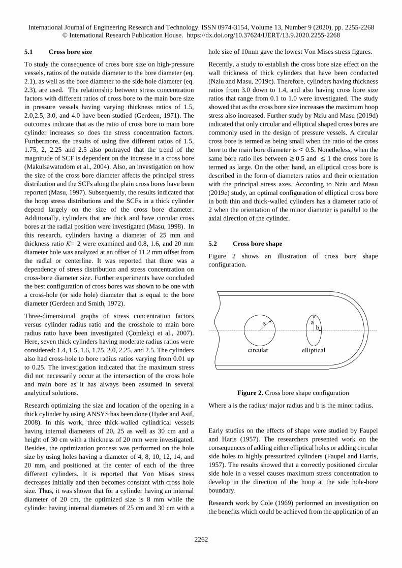
5.2 Cross bore shape
Figure 2 shows an illustration of cross bore shape
configuration.
Figure 2. Cross bore shape configuration
Where a is the radius/ major radius and b is the minor radius.
Early studies on the effects of shape were studied by Faupel
and Haris (1957). The researchers presented work on the
consequences of adding either elliptical holes or adding circular
side holes to highly pressurized cylinders (Faupel and Harris,
1957). The results showed that a correctly positioned circular
side hole in a vessel causes maximum stress concentration to
develop in the direction of the hoop at the side hole-bore
boundary.
Research work by Cole (1969) performed an investigation on
the benefits which could be achieved from the application of an

International Journal of Engineering Research and Technology. ISSN 0974-3154, Volume 13, Number 9 (2020), pp. 2255-2268
© International Research Publication House. https://dx.doi.org/10.37624/IJERT/13.9.2020.2255-2268
2263
oblique, or offset the axis for a hole for circular section, or the
effects of an elliptical cross-section. The study concluded that
there was the possibility to recover a large portion of the
capacity to handle the pressure that is ‘lost’ by the application
of a cross-bore elliptical cross-section. To decrease SCFs, the
measurements of the outlet ellipse that is shaped when the
cross-bore plunges into the main cylinder bore should be in a
way that there is equal major to minor axes for maximum stress
at the ends (Cole et al., 1976). To fulfill this need, an
approximate aspect ratio of 2 was established (Masu, 1997).
With the use of finite element analysis gaining popularity,
cylinders having optimally shaped elliptical radial cross bore
that is, radially positioned or offset circular cross bore were
analyzed (Masu, 1997). The results showed that a cylinder
having radial elliptical cross bore cylinders develops almost 1.5
times hoop stress than that of circular radial cross bore. This
result was later reinforced by Maskulwatudom (2004) where it
was reported that centered elliptical cross holes reduce the
SCFs considerably but in general lead to higher production
costs (Makulsawatudom et al., 2004). The research work went
further and reported that the offset circular cross hole which is
cheaper to manufacture, reduces the SCF effect however the
decease is much lesser than that of an elliptical cross-section
crosshole.
Additional study has been reported on the effect of small
transverse holes in cylinders having either chamfer or radius on
fatigue life of a thick-walled cylinder (Masu and Craggs, 1992).
The researchers we surprised that cross-bore cylinders that are
plain and having thick ratios K=1.4, as well as a thickness ratio
of 2.0, have a fatigue strength that is slightly more than similar
cylinders with blending characteristics. More research was
done on how size and chamfers affect stress distribution in a
thick-walled cylinder having cross bore cylinders that are
subjected to pressure and have been reported (Kihiu and Masu,
1995). In this work, by varying chamfer angle against a fixed
chamfer size and also varying the chamfer length against a
fixed chamfer angle, the reaction of stress distribution and
SCFs were investigated. The investigation also showed that by
introducing chamfers to cross bores in cylinders, stress starts to
redistribute. These findings matched a different investigation
conducted by Makulsawatudom et al (2004). With further
developments in finite element analysis and computer hardware
technology, Peters (2003) reevaluated many theories that had
been developed earlier. Hence, an investigation on the
application of a blend radius to the inside junction of a vessel
cross bore vicinity of the hole and stress concentrations
established around the hole was done (Peters, 2003). The
research gave mixed results from Masu and Craggs (1992)
work. It reported that small blend ratios can reduce stress
concentration by up to 6% in certain cases and also may
increase by up to 10%. Another study on elastic SCFs for
pressurized vessels having a radial circular, offset circular, and
elliptical shaped cross holes have been reported
(Makulsawatudom et al., 2004). In this work plain, chamfered,
and radius types of connection between the cross hole and main
bore were investigated. The study concluded that the
introduction of a blend radius or chamfer at the junction
diminishes the stress concentration at the main bore but has an
effect of introducing higher peak stress elsewhere in the blend
or chamfer area. Further investigation of universal SCFs and
optimal chamfering in cross bored cylinders have been
conducted (Kihiu et al., 2007). It was found that chamfers are
more suitable for thick cylinders than thick cylinders.
A study on stress concentration factors in pressure vessels with
elliptical cross bores has been done (Adenya and Kihiu, 2010).
The researchers observed a decrease of stress concentration
factor if an elliptical-shaped cross bore whose major axis was
normal to the cylinder axis and was rotated clockwise to the
longitudinal plane by 90 degrees. At this position, the minimum
stress concentration factor was found to be less than 2. The
investigation developed a conclusion that the maximum stress
concentration factors occurred when the major axis of the
elliptical cross bore lay in the longitudinal plane. While the
minimum SCFS developed when the major axis of the elliptical
cross bore lay in the transverse plane.
Stress concentration mitigation techniques have been reported
by Nagpal (2012). The paper reported that if you smoothen
stress flows lines around the vicinity, stress concentration in the
vicinity of singularity can be minimized (Nagpal et al., 2012).
The authors proposed some ways of mitigation which include
the elimination of material from the vicinity by introducing
auxiliary holes, hole shape optimization, and reinforcement of
the hole by introducing material. However, the authors noted
that shape discontinuities optimization for mitigation of stress
concentration may not always be practical because it can be
hampered by design constraints, like in case of bolt holes, rivets
holes among others.
Finally, analyses have been performed to establish the optimal
shape between circular and elliptical plain cross bore at radial
and offset positions in closed thick-walled cylinders (Nziu and
Masu, 2019b). The paper reported that elliptical shaped cross
bore predicted lower hoop stresses at a radial position than
circular ones, with a variation of 44.6% to 66.9% across the
studied ratios. The authors concluded that the optimal location
of elliptical cross bores reduces SCF magnitudes by 33% in
comparison to a similar cross bore.
5.3 Cross bore Location
Whenever a cross bore is positioned at the centroidal axis of the
cylinder is known as a radial cross bore(Nziu and Masu,
2019c). Whereas, offset cross bores refers to laying of the cross
bore in any other chord away from the centroidal axis. These
terminologies are illustrated in Figures 3 to 4.

International Journal of Engineering Research and Technology. ISSN 0974-3154, Volume 13, Number 9 (2020), pp. 2255-2268
© International Research Publication House. https://dx.doi.org/10.37624/IJERT/13.9.2020.2255-2268
2264
Figure 3. Radial cross bore Figure 4. Offset cross bore
Researchers have reported the effect of introducing elliptically
or circular shaped side holes to thick-walled cylinders (Faupel
and Harris, 1957), and equation 2.5 was the formula developed
by Morrison et al (1959), to obtain SCF at a radial position.
Identifying the right location of the holes henceforth developed
an incredible interest. Therefore, a study on the strength of
thick-walled vessels having offset or radial circular shaped
cross bores has been reported (Cole et al., 1976). The
investigation concluded that offsetting small cross bores from
the centerline in a cylinder can increase the fatigue life of a
vessel.
Investigations on the comparison of cylinders having either a
circular radial shaped cross bore and optimally circular cross
bore that is offset from the radial line has been reported (Masu,
1997). This research arose from the need for information on the
effect of location on stress distribution and stress concentration.
A circular cross bore having a diameter of 1.6 mm at the radial
position that has been offset by 11.2 mm from the centerline
was investigated. The author reported that changing the
configuration or offsetting the cross bore is reported to greatly
reduce the hoop stress in a plain cross bore cylinder. Therefore,
Masu (1997) supported experimentally that by offsetting a
cross bore by 11.2 mm from the radial centerline of the vessel,
there was a significant increase in the fatigue life of by up to
170%. Another work on an analysis of circular offset cross bore
cylinder has been reported by Masu(1998). Cylinders having
thickness ratios of K=2 with a diameter of 1.6mm and the hole
at radial position, 6 mm offset position, and also 11.2 mm from
the radial centerline were analyzed(Masu, 1998). Hence, by use
of finite element analysis, the study concluded that cylinder
stress analysis shows that the maximum hoop stresses in the
circular radial cross bore cylinders were reaching almost 1.73
times that of the cross-hole cylinder that has been offset by 11.2
mm. Additionally, Makulsawatudom (2004) reported that,
offset circular cross hole, which is cheaper to construct than
elliptical cross holes, reduces the stress concentration effect
however the reduction of stress concentration is lower than that
of an elliptical cross hole.
Research on stress concentration at radial cross holes in thick
cylinders that are pressurized has been presented (Çömlekçi et
al., 2007). The analysis showed that the location of maximum
stress does not necessarily occur at the intersection between the
bore and main cylinders, as is normally expected to be, but it
occurs elsewhere up the cross hole from the intersection.
Another work on location optimization for the opening in a
pressure vessel has been reported (Hyder and Asif, 2008).
Hence, an analysis of a hole having a diameter of 12mm hole
and is located at 0.0625, 0.125, 0.25, 0.375, 𝑎𝑛𝑑 0.5 away
from the top of the cylinder height in three different cylinders
of 20, 25 and 30 cm, for location optimization was carried out.
Results indicated that Von Mises stress is at peak at the radial
position which is location 0.5 location and is decreasing from
the center and however, the stress increases as the location are
changed from 0.125 𝑡𝑜 0.0625 from the cylinder due to the end
effects. Subsequently, the location of the hole that was
optimum was observed to be at the location 0.125 of the
cylinder height.
FEA has been conducted on an elastic pressurized thick-walled
cylinder to determine the optimal location for an elliptical-
shaped cross bore (Nziu and Masu, 2019d). The authors
established that the offsetting of an elliptically shaped cross
bore increases the magnitude of SCFs and noted that the lowest
SCF occurred at the radial position when K=2.5 with a
magnitude of 1.733. Additionally, the same authors researched
to determine the optimal location of a circular cross-bore in
thick-walled pressure vessels (Nziu and Masu, 2019e). The
research established that the offsetting of circular-shaped cross
bores appropriately reduces the magnitude of SCFs. Besides,
the optimal location was found to be at 0.9 offset position for a
thick-walled cylinder having a thickness ratio of 1.4, and stress
concentration factor of 2.312. This stress concentration factor
showed a decrease of pressure carrying capacity of the cylinder
by 56.7% as compared to the same plain cylinder without a
cross bore.
5.4 Cross bore obliquity
An oblique hole in a surface is a hole whose axis that is not
perpendicular to the plane of the surface (Stanley and Day,
International Journal of Engineering Research and Technology. ISSN 0974-3154, Volume 13, Number 9 (2020), pp. 2255-2268
© International Research Publication House. https://dx.doi.org/10.37624/IJERT/13.9.2020.2255-2268
2265
1990) and therefore the obliquity (α) angle which is the angle
between the hole axis and also the plate normal (Stanley and
Starr, 2000). Simpler configurations of the normal cross hole in
thick-walled cylinders are commonly available and the
application of oblique cross bore holes would be needed when
unusual constraints are considered which include applications
that have restrictive geometries, extraction probes or involving
specialized spargers (Nihous et al., 2008).
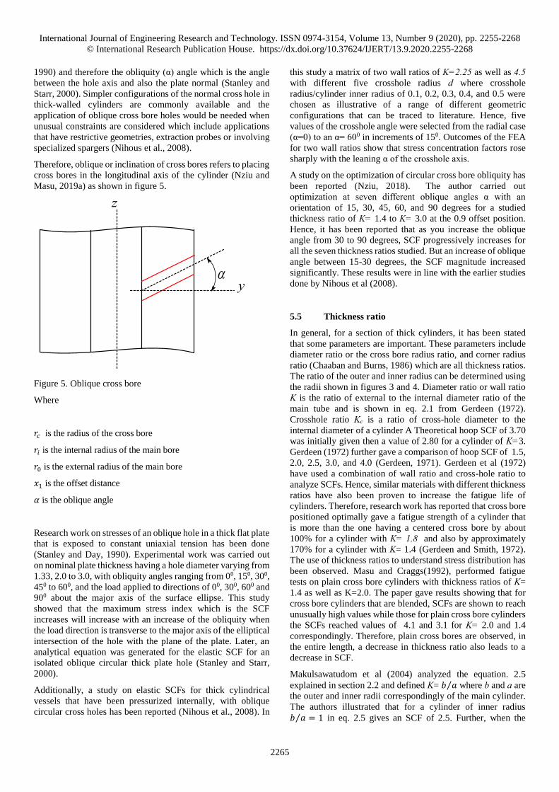
Therefore, oblique or inclination of cross bores refers to placing
cross bores in the longitudinal axis of the cylinder (Nziu and
Masu, 2019a) as shown in figure 5.
Figure 5. Oblique cross bore
Where
𝑟𝑐 is the radius of the cross bore
𝑟𝑖 is the internal radius of the main bore
𝑟0 is the external radius of the main bore
𝑥1 is the offset distance
𝛼 is the oblique angle
Research work on stresses of an oblique hole in a thick flat plate
that is exposed to constant uniaxial tension has been done
(Stanley and Day, 1990). Experimental work was carried out
on nominal plate thickness having a hole diameter varying from
1.33, 2.0 to 3.0, with obliquity angles ranging from 00, 150, 300,
450 to 600, and the load applied to directions of 00, 300, 600 and
900 about the major axis of the surface ellipse. This study
showed that the maximum stress index which is the SCF
increases will increase with an increase of the obliquity when
the load direction is transverse to the major axis of the elliptical
intersection of the hole with the plane of the plate. Later, an
analytical equation was generated for the elastic SCF for an
isolated oblique circular thick plate hole (Stanley and Starr,
2000).
Additionally, a study on elastic SCFs for thick cylindrical
vessels that have been pressurized internally, with oblique
circular cross holes has been reported (Nihous et al., 2008). In
this study a matrix of two wall ratios of K=2.25 as well as 4.5 with different five crosshole radius d where crosshole
radius/cylinder inner radius of 0.1, 0.2, 0.3, 0.4, and 0.5 were
chosen as illustrative of a range of different geometric
configurations that can be traced to literature. Hence, five
values of the crosshole angle were selected from the radial case
(α=0) to an α= 600 in increments of 150. Outcomes of the FEA
for two wall ratios show that stress concentration factors rose
sharply with the leaning α of the crosshole axis.
A study on the optimization of circular cross bore obliquity has
been reported (Nziu, 2018). The author carried out
optimization at seven different oblique angles α with an
orientation of 15, 30, 45, 60, and 90 degrees for a studied
thickness ratio of K= 1.4 to K= 3.0 at the 0.9 offset position.
Hence, it has been reported that as you increase the oblique
angle from 30 to 90 degrees, SCF progressively increases for
all the seven thickness ratios studied. But an increase of oblique
angle between 15-30 degrees, the SCF magnitude increased
significantly. These results were in line with the earlier studies
done by Nihous et al (2008).
5.5 Thickness ratio
In general, for a section of thick cylinders, it has been stated
that some parameters are important. These parameters include
diameter ratio or the cross bore radius ratio, and corner radius
ratio (Chaaban and Burns, 1986) which are all thickness ratios.
The ratio of the outer and inner radius can be determined using
the radii shown in figures 3 and 4. Diameter ratio or wall ratio
K is the ratio of external to the internal diameter ratio of the
main tube and is shown in eq. 2.1 from Gerdeen (1972).
Crosshole ratio Kc is a ratio of cross-hole diameter to the
internal diameter of a cylinder A Theoretical hoop SCF of 3.70
was initially given then a value of 2.80 for a cylinder of K=3.
Gerdeen (1972) further gave a comparison of hoop SCF of 1.5,
2.0, 2.5, 3.0, and 4.0 (Gerdeen, 1971). Gerdeen et al (1972)
have used a combination of wall ratio and cross-hole ratio to
analyze SCFs. Hence, similar materials with different thickness
ratios have also been proven to increase the fatigue life of
cylinders. Therefore, research work has reported that cross bore
positioned optimally gave a fatigue strength of a cylinder that
is more than the one having a centered cross bore by about
100% for a cylinder with K= 1.8 and also by approximately
170% for a cylinder with K= 1.4 (Gerdeen and Smith, 1972).
The use of thickness ratios to understand stress distribution has
been observed. Masu and Craggs(1992), performed fatigue
tests on plain cross bore cylinders with thickness ratios of K=
1.4 as well as K=2.0. The paper gave results showing that for
cross bore cylinders that are blended, SCFs are shown to reach
unusually high values while those for plain cross bore cylinders
the SCFs reached values of 4.1 and 3.1 for K= 2.0 and 1.4
correspondingly. Therefore, plain cross bores are observed, in
the entire length, a decrease in thickness ratio also leads to a
decrease in SCF.
Makulsawatudom et al (2004) analyzed the equation. 2.5
explained in section 2.2 and defined K= 𝑏 𝑎⁄ where b and a are
the outer and inner radii correspondingly of the main cylinder.
The authors illustrated that for a cylinder of inner radius
𝑏 𝑎 = 1⁄ in eq. 2.5 gives an SCF of 2.5. Further, when the

International Journal of Engineering Research and Technology. ISSN 0974-3154, Volume 13, Number 9 (2020), pp. 2255-2268
© International Research Publication House. https://dx.doi.org/10.37624/IJERT/13.9.2020.2255-2268
2266
thickness ratio increases, the SCF also increases. For example
a cylinder radius ratio 𝑏 𝑎 = 2⁄ has a maximum stress
concentration factor of 3.4. The researchers thus went further
to analyze five cylinders with different radius ratios of
𝑏 𝑎⁄ 𝑜𝑓 1.5, 1.75, 2, 2.25 𝑎𝑛𝑑 2.5. Also, two different circular
cross holes having different radii were analyzed where radius
Rc = 0.01b as well as Rc= 0.05b. The results gave an overall
conclusion that the SCF effect was more for the smaller hole,
however, a difference of 5% was observed.
Research on the investigation of SCFs as a function of the ratio
of cross bore radius to the cylinder internal radius where
K=0.01 varied to 0.07 for a variety of wall ratios of Ks= 1.5 to
5 using finite element method has been discussed (Dixon et al.,
2002). The paper presented charts detailing the effects of cross
bore radius ratios on hoop SCFs in cylinders and blocks. It was
concluded that the SCFs in blocks are very similar to those in
cylinders with cross bores.
A study on the effects of wall thickness on pressurized elastic
thick cylinders has been reported (Nziu and Masu, 2019c). The
study aimed to investigate the optimal SCFs as well as the
behavior of hoop stress. Cylinders having thickness ratios
varying from 3.0 up to 1.4 with cross bore to main bore ratio
starting from 0.1 to 1.0 were investigated. With the five circular
radial cross bore size ratios analyzed, the smallest cross bore
size ratio of 0.1, generated the minimum hoop stress while the
maximum stress occurred with a cross bore size of 1.0. Further,
the minimum SCF occurred in the smallest cross bore size ratio
of 0.1 at a thickness ratio of 2.25 with a stress concentration
factor of approximately 2.836.
In conclusion, it is clearly shown that geometric design
parameters of cross bore size, shape, location, obliquity, and
thickness ratios affect stress distribution and SCFs in pressure
vessels. Hence, the optimal configuration of these parameters
on compound thick compound cylinders becomes essential in
design.
6 SUMMARY DISCUSSION
This literature survey has reviewed three critical areas that help
in understanding the design of pressure vessels. They are Stress
Concentration Factors (SCF), measurement of stress
distribution, and geometric design parameters affecting stress
concentration in high-pressure vessels. Investigation of stress
distribution in high-pressure vessels can be measured by
experimental, analytical, or numerical techniques. Therefore,
numerical modeling using FEA Abaqus software will be used
to determine SCFs in thick compound cylinders with a cross
bore in this study. Furthermore, from the study on the literature
on compound cylinders, it is clearly shown that most
investigations and research tend towards the optimization of
compound cylinders based on specific parameters that affect
the design of compound cylinders like interference. The
parameters include shrink radius, diametral interference,
material, autofrettage, and other geometries. There is no
available information on the effects of cross bores in thick
compound cylinders. Additionally, it is also illustrated that
geometric design parameters of cross bore size, shape, location,
obliquity, and thickness ratios affect stress distribution and
SCFs in pressure vessels.
7 CONCLUSION STATEMENT
The optimal configuration of geometric design parameters on
compound thick compound cylinders is essential in design. It
is, therefore, noted that from the current review that there is no
available literature of study using finite element analysis of
thick compound cylinders having cross bores. Hence, this study
was justified to extensively investigate the effect of geometric
design parameters of cross bore size, shape, location, obliquity,
and thickness ratio on stress concentration in thick compound
cylinders and high-pressure vessels.
ABBREVIATION
SCF: Stress Concentration Factor; FEA: Finite Element
Analysis
ACKNOWLEDGMENT
This research work is supported by the Vaal University of
Technology. The authors wish to thank the Department of
Mechanical Engineering at the Vaal University of Technology
for facilitating this work.
Availability of data and material
All cited articles in this review article are available upon
request.
Authors’ contributions
All authors jointly contributed to the development of this
journal article.
Competing interests
The authors declare that they have no competing interests.
REFERENCES
Adenya, C.A. and Kihiu, J.M. (2010), “Stress Concentration
Factors in Thick Walled Cylinders With Elliptical Cross-
Bores”, Jomo Kenyatta University of Agriculture and Technology. Digital Repository, pp. 181–200.
Bahoum, K., Diany, M. and Mabrouki, M. (2017), “Stress
analysis of compound cylinders subjected to thermo-
mechanical loads”, Journal of Mechanical Science and Technology, Vol. 31 No. 4, pp. 1805–1811.
Chaaban, A. and Burns, D.J. (1986), “Design of high pressure
vessels with radial crossbores”, Physica B+C, North-
Holland, Vol. 139–140, pp. 766–772.
Cole, B.N. (1969), “Strategy for Cross-Bores in High Pressure
Containers”, Journal of Mechanical Engineering Science, IMECHE, Vol. 11 No. 2, pp. 151–161.
Cole, B.N., Craggs, G. and Ficenec, I. (1976), “Strength of
Cylinders Containing Radial or Offset Cross-Bores.”, J Mech Eng Sci, IMECHE, Vol. 18 No. 6, pp. 279–286.
International Journal of Engineering Research and Technology. ISSN 0974-3154, Volume 13, Number 9 (2020), pp. 2255-2268
© International Research Publication House. https://dx.doi.org/10.37624/IJERT/13.9.2020.2255-2268
2267
Çömlekçi, T., Mackenzie, D. and Wood, J. (2007), “Elastic
stress concentration at radial crossholes in pressurized
thick cylinders”, Journal of Strain Analysis for Engineering Design, Vol. 42, pp. 461–468.
Dharmin, P., Khushbu, P. and Chetan, J. (2012), “A Review on
Stress Analysis of an Infinite Plate with”, International Journal of Scientific and Research Publications, Vol. 2
No. 11, pp. 1–7.
Dixon, R.D., Peters, D.T. and Keltjens, J.G.M. (2002), “Stress
Concentration Factors of Cross-Bores in Thick Walled
Cylinders and Square Blocks”, ASME Pressure Vessels and Piping Conference, Vancouver BC, pp. 31–36.
Faupel, J.H. and Harris, D.B. (1957), “Stress Concentration in
Heavy-Walled Cylindrical Pressure Vessels - Effect of
Elliptic and Circular Side Holes”, Industrial & Engineering Chemistry, American Chemical Society,
Vol. 49 No. 12, pp. 1979–1986.
Fessler, H. and Lewin, B. (1956), “Stress distribution in a tee
junction of thick pipes”, British Journal of Applied Physics, Vol. 7, p. 76.
Ford, H. and Alexander, J. (1977), Advanced Mechanics of Material, Second Edi., John wiley and sons inc., Canada.
Gerdeen, J. (1971), “Analysis of stress concentrations in thick
cylinders with sideholes and crossholes”, ASME Pap 71-WA/PVP-9 for Meeting, Vol. 94 No. 3, p. 815.
Gerdeen, J.C. and Smith, R.E. (1972), “Experimental
determination of stress-concentration factors in thick-
walled cylinders with crossholes and sideholes”,
Experimental Mechanics, Vol. 12 No. 11, pp. 530–536.
Hearn, E. (1997), MECHANICS OF MATERIALS 2, 3rd ed.,
BUTTERWORTH HEINEMANN.
Hyder, M.J. and Asif, M. (2008), “Optimization of location and
size of opening in a pressure vessel cylinder using
ANSYS”, Engineering Failure Analysis, Vol. 15 No. 1,
pp. 1–19.
Kharat, A. and Kulkarni, V. (2013), “Stress Concentration at
Openings in Pressure Vessels–A Review”, Int. j. Innov. Res. Sci. Eng. Technol., Vol. 2 No. 3, pp. 670–678.
Kihiu, J.. (2002), Numerical Stress Characterization in Cross Bored Thick Walled Cylinders under Internal Pressure,
The University of Nairobi.
Kihiu, J. and Masu, L. (1995), “The effect of chamfer and size
on the stress distributions in a thick-walled cylinder with
a cross bore under internal pressure”, Jomo Kenyatta University of Agriculture and Technology. Digital Repository, Vol. 2 No. February, pp. 73–78.
Kihiu, J.M., Rading, G.O. and Mutuli, S.M. (2007), “Universal
SCFs and optimal chamfering in cross-bored cylinders”,
International Journal of Pressure Vessels and Piping,
Vol. 84 No. 6, pp. 396–404.
Kumaresan, M. and Chocklingam. (2018), “Stress Analysis in
Compound Cylinder and Autofrettaged Cylinders”,
International Journal of Engineering Research and Technology, Vol. 7 No. 4.
Majumder, T., Sarkar, S., Mondal, S. and Mandal, D. (2014),
“Optimum Design of Three Layer Compound Cylinder”,
IOSR Journal of Mechanical and Civil Engineering, Vol.
11, pp. 33–41.
Majzoobi, G.H., Farrahi, G.H., Pipelzadeh, M.K. and Akbari,
K. (2004), “Experimental and finite element prediction of
bursting pressure in compound cylinders”, International Journal of Pressure Vessels and Piping, Vol. 81 No. 12,
pp. 889–896.
Majzoobi, G.H. and Ghomi, A. (2006), “Optimization of
compound pressure cylinders”, Journal of Achievements in Materials and Manufacturing Engineering, Vol. 15.
Makulsawatudom, P., Mackenzie, D. and Hamilton, R. (2004),
“Stress concentration at crossholes in thick cylindrical
vessels”, The Journal of Strain Analysis for Engineering Design, IMECHE, Vol. 39 No. 5, pp. 471–481.
Masu, L.M. (1989), The Effect of Cross Bore Geometry on the Strength of Pressure Vessels, University of Leeds.
Masu, L.M. (1991), “Cross bore geometry effects on the
strength of pressure vessels”, Proceedings of the International Conference on Mechanics of Solids and Structures, Nayang Technological University,
Singapore, pp. 261–272.
Masu, L.M. (1997), “Cross bore configuration and size effects
on the stress distribution in thick-walled cylinders”,
International Journal of Pressure Vessels and Piping,
Vol. 72 No. 2, pp. 171–176.
Masu, L.M. (1998), “Numerical analysis of cylinders
containing circular offset cross-bores”, International Journal of Pressure Vessels and Piping, Vol. 75 No. 3,
pp. 191–196.
Masu, L.M. and Craggs, G. (1992), “Fatigue Strength of Thick-
Walled Cylinders Containing Cross Bores with Blending
Features”, Proceedings of the Institution of Mechanical Engineers, Part C: Journal of Mechanical Engineering Science, IMECHE, Vol. 206 No. 5, pp. 299–309.
Morrison, J.L.M., Fessler, H., Lewin, B.H., Crossland, B.,
Parry, J.S.C., Faupel, J.H., Harris, D.B., et al. (1959),
“Lake, G. F., Proc. Inst. Conf. Fatigue of Metals, Inst.
Mech. Engrs., London, 743 (1956).”, J. Ind. Chem., Vol.
7.
Nagpal, S., Jain, N. and Sanyal, S. (2012), “Stress
Concentration and Its Mitigation Techniques in Flat Plate
with Singularities - A Critical Review”, Engineering Journal, Vol. 16, pp. 1–16.
Nihous, G.C., Kinoshita, C.K. and Masutani, S.M. (2008),
“Stress concentration factors for oblique holes in
pressurized thick-walled cylinders”, Journal of Pressure Vessel Technology, Transactions of the ASME, Vol. 130
No. 2, pp. 0212021–0212027.
Nziu, P.K. (2018), Optimal Geometric Configuration of a Cross Bore in High Pressure Vessels. In Doctorate Thesis, Vaal University of Technology.
Nziu, P.K. and Masu, L.M. (2019a), “Cross bore geometry
configuration effects on stress concentration in high-
pressure vessels: a review”, International Journal of Mechanical and Materials Engineering, Vol. 14 No. 1, p.
6.
Nziu, P.K. and Masu, L.M. (2019b), “Configuration of optimal

International Journal of Engineering Research and Technology. ISSN 0974-3154, Volume 13, Number 9 (2020), pp. 2255-2268
© International Research Publication House. https://dx.doi.org/10.37624/IJERT/13.9.2020.2255-2268
2268
cross bore shape in elastic pressurized high pressure
vessels”, International Journal of Mechanical and Production Engineering Research and Development, Vol. 9 No. 5, pp. 197–210.
Nziu, P.K. and Masu, L.M. (2019c), “Cross bore size and wall
thickness effects on elastic pressurised thick cylinders”,
International Journal of Mechanical and Materials Engineering, Vol. 14 No. 1, p. 4.
Nziu, P.K. and Masu, L.M. (2019d), “An Optimal Location of
Elliptical Cross Bore in Elastic Pressurized Thick
Cylinders”, International Journal of Mechanical and Production Engineering Research and Development, Vol. 9, pp. 287–298.
Nziu, P.K. and Masu, L.M. (2019e), “Offsetting of Circular
Cross Bore Effects on Elastic Pressurized Thick
Cylinders”, International Journal of Mechanical and Production Engineering Research and Development, Vol. 9, pp. 71–82.
Patil, A. (2013), “Finite element analysis of optimized
compound cylinder”, Journal of Mechanical Engineering Research, Vol. 5 No. 5, pp. 90–96.
Peters, D. (2003), Effect of Blend Radius on Stress Concentration Factor of Crossbored Holes in Thick Walled Pressure Vessels, American Society of Mechanical Engineers, Pressure Vessels and Piping Division (Publication) PVP, Vol. 455.
Qadir, M. and Redekop, D. (2009), “SCF analysis of a
pressurized vessel–nozzle intersection with wall
thinning damage”, International Journal of Pressure Vessels and Piping, Vol. 86 No. 8, pp. 541–549.
Reghunath, R. and Sammon, K. (2014), “Analysis of Internally
Pressurised Thick Walled Cylinders”, Journal of Basic and Applied Engineering Research, Vol. 1 No. 2, pp. 83–
89.
Stanley, P. and Day, B. V. (1990), “Photoelastic investigation
of stresses at an oblique hole in a thick flat plate under
uniform uniaxial tension”, The Journal of Strain Analysis for Engineering Design, IMECHE, Vol. 25 No. 3, pp.
157–175.
Stanley, P. and Starr, A.G. (2000), “Stress concentrations at an
oblique hole in a thick plate”, The Journal of Strain Analysis for Engineering Design, IMECHE, Vol. 35 No.
2, pp. 143–147.
Zhang, Q., Wang, Z.W., Tang, C.Y., Hu, D.P., Liu, P.Q. and
Xia, L.Z. (2012), “Analytical solution of the thermo-
mechanical stresses in a multilayered composite pressure
vessel considering the influence of the closed ends”,
International Journal of Pressure Vessels and Piping,
Vol. 98, pp. 102–110.