streetscape policy and guidance - enfield
TRANSCRIPT

Streetscape Policy and Guidance
Volume 2
Guidance
Standards & Procedures Good Practice
Technical Specifications Standard Drawings
Approved March 2012

The Policy and Guidance Document is in two volumes. This volume (Volume 2 Guidance) contains four sections. Section 1: Standards and Procedures; provides general information on design, the standard specifications adopted in Enfield and procedures in relation to works on or affecting the public highway. Section 2: Good Practice; contains guidance and practices which can enhance the quality of street design and workmanship. Section 3: Technical Specifications; gives detailed specifications for specific elements of the streetscape and preferred design choices. It also contains references to recognised guidance documents and regulations. Section 4: Standard Drawings; covers the key requirements for specific items which differ from standard guidance or specifications.
Volume 1 Policy (separately bound) presents the Councils key streetscape policies and key aims and objectives with respect to the streetscape. It looks at the various streetscape components, how various elements of the street scene are treated and how they function in the public realm
Highway Services Environment Department London Borough of Enfield
1
Contents
Page Introduction to Volume 2 5
Standards and Procedures 7
Standard Streetscape Design Guidance 9 Standard Specifications 11 Street Layout and Alignment Design 13 Changes to the Existing Highway Network (New Developments) 15 Adoption of Highways and Highway Structures Under s38 of the Highways Act 19
Good Practice 21 Streetscape Design 23 Paved Footways 25 Footway Drainage 26 Street Furniture and Signs 27 Grass Areas 28 Trees 29 Shrub Beds and Hedges 31
Technical Specifications and Design Guidance 33 Footways:
Paving 35 Flexible 37 Block Paving 39 Tactile Paving 41 Granite Kerbs 43 Concrete Kerbs 45 Conservation Kerb 47 Chambers and Drawpits 49 Domestic Crossover 51 Heavy Duty Crossover 53
Carriageways:
Flexible Construction 55 High Friction Surfacing 57
Traffic Calming Measures 59

2
Signs:
Non Illuminated Traffic Signs 61 Illuminated Traffic Signs 63 Illuminated and Rebound Bollards 65 Pedestrian Direction Signs (Town Centres) 67 Pedestrian Signs (Footpaths, Bridleways and Public Rights of Way) 69 Street Nameplates 71 Standard Sign Posts and Brackets (Non Illuminated) 75 Standard Sign Posts and Brackets (Illuminated) 77 Passive Safety Posts (Non Illuminated) 79 Carriageway Markings 81
Street Furniture:
Cast Iron Bollard 83 Passive safety bollard 85 Timber Bollard 87 Seat (Timber) 89 Seat (Metal) 91 Pedestrian Guard Railing 93 Cycle Stands 95 Protection and Finishes 97
Soft Landscaping:
Grass Areas 99 Tree Species 101 Tree Protection 103 Shrub Beds and Hedges 105 Bulb Planting 107 Top Soil and Mulches 109
Street Lighting:
Lamp Columns and Lanterns 111 Drainage:
Manholes, Gullies, Pipes, etc 113 Hydraulic Data 115
Sustainable Urban Drainage Solutions 117

3
Standard Drawings 119
Footway Detail Drawing No. 01 Street Nameplate Drawing No. 02 Cast Iron Bollard Drawing No. 03 Seat (Timber) Drawing No. 04 Seat (Metal) Drawing No. 05 Tree Anchors (Below Ground) Drawing No. 06 Tree Support (Above Ground) Drawing No. 07 Gully Type 1 Drawing No. 08 Gully Type 2 Drawing No. 09 Gully Type 3 Drawing No. 10

4
Intentionally Blank

5
Introduction to Volume 2 Streets should be attractive places that meet the needs of all users. .Inclusive design principles place people at the heart of the design process, whilst providing sustainable environments that are safe, convenient and enjoyable to use. This part of the guidance is aimed at practitioners and provides more detailed information on procedures affecting those involved with highway issues. It provides technical information, and specifications for specific components of the streetscape, which are required when undertaking any highway works within the London Borough of Enfield. It contains practices and attention to details not necessarily covered in standard specifications, but, where adhered to, can improve the appearance and durability of the public realm and therefore should be considered not as guidance, but minimum standards to be achieved. Enfield recognises and supports the use of standard specifications and design guidance for many aspects of its highway design and construction, but where practices or choices of materials are specific to Enfield, specifications are provided and adherence is required. It is recognised that, in some situations, there will be difficulties in meeting these standards and alternative measures may be required. It is also recognised that the application of these standards may not be the appropriate treatment in all situations and special treatment may be appropriate or necessary. It is not the intention of this guidance to restrict innovation or apply a one size fits all approach regardless of suitability. Proposals should always be discussed and agreed with council officers. It is not the intention of this guidance to provide detailed directions on all aspects of highway design for new developments, but only those common elements which impact on the street scene. For example specific carriageway and footway widths are not given for various road categories, nor is the provision of bus and cycle route facilities covered, important those these are. These should be designed to meet the specific requirement and circumstances applicable in each individual case and in the case of new developments covered at planning stage and are covered in Enfield’s planning guidance. The specification sheets have been produced as separate sheets with version numbers and issue dates to allow for independent updates as required. They are not intended to be detailed contract specifications, but as direction to specific types and standards. Within the specification sections, some suppliers / products have been identified as meeting the specification. This is not a recommendation of a sole supplier and other suppliers / products may be available which meet the specification.

6
Intentionally Blank

7
Standards and
Procedures

8
Intentionally Blank

9
Standard Streetscape Design Guidance There exists a considerable amount of design guidance for street design and layout, applying the principles of contemporary thinking regarding the function of streets. Key technical design guidance and good practice is also available, which should be followed in order to not only meet wider concepts, but also provide fit for purpose roads and footways, where attention to detail can vastly improve the streetscape, its function and design life.
Planning Documents and Guidance: The Council is required to prepare a Local development Framework (LDF) by the Planning and Compulsory Purchase Act 2004. Enfield's LDF will contain a number of documents, one of which is the Enfield Design Guide. On the 15th December 2010, the Council adopted the Enfield Urban Design Declaration to formalise the Council's commitment to good urban design. The Declaration is to be supported by an Urban Design Strategy which will identify key principles and priorities and deliver the commitments made in the Declaration.
Department for Transport's Design Manual for Roads and Bridges: The Department for Transport's (DfT’s) Design Manual for Roads and Bridges (DMRB) sets out the requirements for the design and construction of UK Trunk Roads and Motorways. The Manual has been designed to be compatible with quality assurance schemes of both the DfT and design consultants. The Design Manual pulls together all the various previously published DfT documents, such as the Departmental Standards and Advice Notes within a structured manual system. It can be used for local road schemes to provide best guidance and as such is a fundamental document for highway design, particularly in respect of construction details. However, it should only be applied where appropriate and other documents may be more applicable to local road design particularly layout design.
Manual for Streets: Manual for Streets along with its predecessor document Design Bulletin 32 (and its companion document Places, Streets and People) provides guidance on residential street layout.
Manual for Streets aims to deliver Streets that -
Help to build and strengthen communities; Meet the need of all users; Form part of a well-connected network; Are attractive;

10
Are cost effective to construct and maintain, and are safe
In manual for Streets a street is defined as a highway that has important functions beyond the movement of traffic. Therefore most highways in the built up areas of Enfield can be considered as streets.
Manual for Streets 2: Manual for Streets 2 applies the principles contained in Manual for Streets to non residential roads. it does not supersede Manual for Streets.
Traffic Advisory Leaflets: These leaflets, published by the Department for Transport, provide information, guidance, legislative interpretation and good practice on a range of traffic management design and traffic calming.
Transport in the Urban Environment: Published by the Institution of Highways and Transportation and, although now over 10 years old, this remains a substantive guidance on traffic and transportation infrastructure provision.
Inclusive Mobility: Inclusive Mobility is the Department for Transport’s guidance on designing transport infrastructure for those with mobility and sight impairments. It should be read in conjunction with the DfT’s guidance on the use of tactile paving and this guidance document.

11
Standard Specifications Standard national guidance sets technical specifications covering a large range of products, materials and methods for highways. Enfield’s Streetscape Policy and Guidance sets out the preferred styles, types, material and finishes to be used in Enfield and, where applicable, good practice in order to achieve the high standard that is expected in order to create pleasant, functional and durable places within its road and footway network.
Department for Transport Specification for Highway Works: The Department for Transport Specification for Highway Works is the definitive specification for highways both hard and soft within Enfield. However, local practices and preferred treatments are set out in this guidance and should be followed.
Sewers for Adoption: The Water Authority’s document, sewers for adoption, has become the standard for the design and construction of sewers to adoptable standards and therefore sets out the standards acceptable for highway drainage. Sewers for Adoption does not, however, cover sustainable drainage systems (SUDS), which are now required following introduction of the Water and Flood Management Act 2010. There is currently no definitive design guidance for SUDS and therefore will need to be discussed at an early stage with Council Officers.
Trade Guidance and Suppliers’ Information: A wealth of information is produced by suppliers to support the installation of their products and also by trade organisations associated with the products. This should always be a point of reference when designing in and specifying specific products and is essential with products such as passive safety feature which must be installed correctly to function as intended.

12
Intentionally Blank
13
Street Layout and Alignment Design This general guide is not prescriptive as to the requirements for any given road, as it will rely on its specific function and environment. The street is a key part of the public realm and therefore, its design is as important as the buildings and facilities it serves and should be designed for both movement and the place function. This section is principally aimed at new developments where new roads are being planned, but the principles can be applied to existing roads when improvements and enhancements are considered. The Department for Transport’s design standards for link and junction design are primarily aimed at higher speed trunk roads. Some criteria contained within them is applicable, but in a vast majority of cases careful consideration needs to be given to the circumstances in which those standards should be applied to local roads. Manual for Streets gives guidance on local residential road layout and Manual for Streets 2 shows how the same principles can be applied to more general roads. New design considerations are encouraged, recognising the role of the street in the public realm and its function as a place as well as for movement. Traditional layout criteria can still be found in its predecessor document Design Bulletin 32. The London Borough of Enfield, through its planning guidance and design guides gives direction on the concepts to be applied when designing residential and mixed use developments. However, the format of any road layout and its form should be discussed with the London Borough of Enfield at an early stage in the development of a scheme, particularly if future adoption of the highway is intended under s38 of the Highways Act. Most industrial developments require roads that cater for large vehicles, and need to be designed to accommodate this need. However, certain developments, such as offices, may not generate significant lorry movements. In these cases, the geometry of the roads could be similar to that of residential estates. The road layout should be designed to help minimise the risks of access problems for the emergency services, residents and deliveries. The Council may, where necessary, approve non-standard proposals involving the geometry of the road, which is now supported in Manual for Streets. The increased use of public transport is a fundamental aspect of sustainable development. Therefore, when planning and designing new roads, the need for public transport access must be considered. Discussions should be held at an early stage with the London Borough of Enfield and, where appropriate, bus operators to determine the necessary measures to encourage a safe and efficient service.

14
Junctions: Junction type and design is a critical element as they are the locations where delay, accidents and vehicle emissions tend to be concentrated. The design should set out to minimise these impacts and will be dependant upon traffic flows, pedestrian flows and turning movements.
Footway Clear Zone: Footways must be wide enough to accommodate peak flows of pedestrians and allow for the presence of bus queues, street furniture etc. The concept of a clear zone, whereby a clear unobstructed route is achieved along the footway is sought and this will require careful planning of street furniture and other potential obstructions so that they are aligned.
Utility Services: The position of utility services within either the footway or the carriageway should be planned and coordinated at an early stage so as to ensure ease of future access for maintenance, without traffic or pedestrian disruption. Enhanced detailing of access covers within the paving design and avoidance of other highway features such as dropped kerbs or tactile paving makes a significant contribution to the standard and quality of the finished scheme.
Soft Landscaping: The street layout design should avoid small ‘left over’ areas, which in practice are abandoned or left for some form of soft landscaping. Soft landscaping should be designed in from the start as part of the public realm and streetscape strategy, particularly if it is to form part of the adopted highway and be maintained as such. The retention of existing trees and hedgerows is encouraged. However, rather than be retained in isolation, these need to be incorporated into the design. Commuted sums may be appropriate where planting takes place within the adoptable highway to cover ongoing maintenance costs

15
Changes to the Existing Road Network (New Developments)
A development (particularly where a new/revised access is involved) is likely to have a number of impacts on the adjoining public highway and in the case of major developments, possible changes to the existing road network. In addition to the main procedures that control the design of a highway and streetscape, there are a number of other procedures which are required to be followed. It is not the objective of this streetscape guidance to provide detailed guidance on all procedures, but those where streetscape issue may be affected are outlined in this section. It is important that all the effects on the highway are discussed and resolved at an early stage in the planning application process. Granting of planning permission is not approval to highway related issues even if they are indicated on approved plans. Elements affecting the highway cannot be implemented without the agreement of the Council, as Highway Authority. In addition to specific footway crossover and access requirements, typical issues which can arise are -
Street lighting affected; Street furniture affected; Plant of utility companies affected; Transport operators’ facilities affected; Signs required / affected; Parking restrictions affected; Highway structures affected; and Highway tree/s, shrubs and verges affected.
Circumstances can also change between the initial consideration of the planning application and the time when the permission is being implemented. The Highway includes all parts of adopted roads i.e. footway, verge/shrub bed and carriageway.
Works Undertaken on the Public Highway Under s278 of the Highways Act: Section 278 of the Highways Act covers modifications to the existing public highway as a result of the needs of a new development proposal in association with adjacent development works. Works under this section can be undertaken by the highway authority with a contribution from the developer or undertaken by the developer to the requirements laid down by the Highway Authority.

16
All such works are subject the developer entering into a suitable legal agreement with the Council under s278 of the Highways Act 1980. This is a legal agreement and does not cover the technical aspects in any great detail. Where the works are developer led, detailed calculations, plans, elevations and specifications need to be submitted for Technical Approval. In addition, because the works are taking place on the live network, all works must be undertaken to requirements stipulated by the Highway Authority, including compliance with New Roads and Street Works Act 1991 and Traffic Management Act 2004. This will include providing and obtaining approval to a Road Network Action Plan and noticing to Transport for London, where works affect the Strategic Road Network. Works on the public highway must be undertaken by approved contractors. Contact Highway Services for more details.
Highway Structures: In all cases where a structure (e.g. a retaining wall, bridge, culvert or other building) either supports the highway or land adjacent to the highway, it is necessary for the developer to satisfy the Council of the structural integrity of the structure. The developer is strongly advised to contact the Council at an early stage, regardless of the type of structure Details of the statutory procedures that are necessary before building a structure near the highway are contained in The Management of Highway Structures – A Code of Practice. In all cases of private structures (buildings) over highways, a licence under section 177 of the Highways Act must be obtained from the Council.
At the outset, it is necessary to establish the following:
whether Technical Approval is required for the structure; and
whether the structure is to be adopted by the Council. Irrespective of whether adoption takes place, Technical Approval is required for the following types of structure:
bridges and culverts with a span of 0.90 metres or greater;
walls supporting the highway with a retained height of 1.40 metres or greater, and
walls supporting land above the highway with a retained height of 1.40 metres or greater and closer to the highway than 3.70 metres.
The developer shall submit full drawings prepared and signed by a Chartered Engineer (Civil or Structural) together with a Certificate 1(A) to the Council before commencement of the works. (This is a statutory requirement under s167 of the Highways Act).

17
Street Lighting and Illuminated Signs: All street lighting in Enfield is operated and maintained under a PFI contract with ETDE Infrastructure Ltd. Street lighting, illuminated bollards (including non illuminated rebound bollard alternatives) and illuminated signs must comply with the requirements laid down by the PFI Contractor, who will advise on detailed specifications and approval procedures.
Traffic Signals: Transport for London (TfL) is the Traffic Authority for all traffic signal installations and the operation of London’s traffic signal control system. A proposal that involves a new traffic signal installation or modification of an existing installation must be discussed with TfL’s Traffic Signal Group via the London Borough of Enfield, Traffic and Transportation Services. The Traffic Signal Group will work closely with Enfield’s engineers and the developer’s consultants in properly considering proposals with the intention of identifying a traffic signal scheme that satisfies local authority aspirations, but meets wider strategic network considerations, overall operation of London’s Traffic Signal Control System, Network Management Duty and safety obligations. TfL’s Traffic Signal Group will prepare a Traffic Signals Supplementary Report which will form the basis of any required notification to TfL. A lot of the information to allow the report to be prepared will need to be provided by the developer’s consultants who may also be responsible for initial modelling work if not undertaken by TfL. Any work undertaken by TfL Traffic Signal Group will be at the developer’s expense. Traffic signal installations are complex specialist work and must meet the requirements of the Traffic Signal Group’s latest specification. Generally civil engineering installations, including signal poles will be undertaken by Enfield or the developers contractor to the specification and design requirements laid down by TfL. The signal installation and commissioning will be undertaken by TfL’s contractor.
Statutory Utility Company Apparatus: Works on the public highway can impact on the apparatus and service connections of the statutory utility companies. This may require diversion work to relocate plant or minor adjustment of their access chamber covers. The approved Code of Practice. ’Measures Necessary Where Apparatus is Affected by Major Works (Diversionary Works)’ June 1992 and in particular Appendix C sets out the recommended procedures to be adopted for consultation, planning and the

18
execution of any undertakers’ works which may be required as a result of highway works
Generally where minor modifications to the level of the cover of an access chamber is required this can be undertaken by the contractor undertaking the highway works, however, the specification of the relevant statutory utility must be adhered to, particularly with respect to the type of cover and in most instances where new covers are required these are supplied by the statutory utility company.
Strategic Road Network:
Certain roads in Enfield are designated part of the Strategic Routes Network (SRN) under the Traffic Management Act. These routes form a strategic route network throughout London and all schemes and works on them or near by and likely to affect traffic on them must be notified to and approved by Transport for London (TfL) Network Assurance Team. Roads in Enfield forming the SRN are as follows: -
A111 Stag Hill, Cockfosters Road, Chase Side, The Bourne, Bourne Hill and Hedge Lane. A110 Bramley Road, Enfield Road, Slades Hill, Windmill Hill, Church Street (and complementary one-way working in Enfield Town), Southbury Road, Nags Head Road and Lea Valley Road. A105 Green Lanes, Ridge Avenue, Park Avenue and London Road. A1010 Fore Street, Hertford Road and High Street (Ponders End)
Any promoter external to Enfield will need to make these notices through Enfield Council as they are made through a restricted web link. In order to avoid planning applications being approved without appropriate comment from TfL it is recommended that developers submit core information via L.B Enfield. Information provided with the Notice must be sufficient to allow TfL to understand the intent and impacts of the scheme. However, the level of information required needs to match the scale of impact of a particular scheme or works.

19
Adoption of Roads and Structures Under s38 of the Highways Act
Roads for Adoption Under s38 of the Highways Act: Planning consent for new development is granted by Enfield Council as the Local Planning Authority under the provisions of the Town and Country Planning Act 1990. However, planning consent does not necessarily mean that the Council would automatically accept for adoption the roads incorporated into the development proposals. Matters dealt with under planning legislation do not cover all the technical aspects of design and construction required by the Council. The developer should approach the Council to negotiate an Agreement under Section 38 of the Highways Act 1980. An Agreement ensures that the estate roads and footpaths will be adopted. This however, is a legal agreement and does not cover the technical aspects in any great detail. Detailed calculations, plans, elevations and specifications need to be submitted for Technical Approval. The developer will meet all the council’s costs of compiling the Agreement, approving designs and inspections. Works on site will be supervised during construction, on completion and 12 months after completion (at the end of the defects liability period) when the adoption will be approved and any bond released. Any highway therefore will be in use before being fully adopted. The Council will NOT adopt any road where the sewer beneath has not been adopted by Thames water as a public sewer. This is a prerequisite of any adoption.
Structures to be Adopted:
Any structure that supports the highway is considered to be part of the highway. The future maintenance responsibility of the structure, however, only passes to the Council if it is adopted under section 38 of the Highways Act.
The developer should approach the Council to negotiate an Agreement under Section 38 of the Highways Act 1980. An Agreement ensures that the structure will be adopted. This however, is a legal agreement and does cover the technical aspects in any great detail which are covered in the Technical Approval. A structure to be adopted will need to meet rigid requirements and must be safe, durable and designed for minimum ongoing maintenance. The developer will meet all the council’s costs of compiling the Agreement, approving designs and inspections.

20
Works on site will be supervised during construction, on completion and 12 months after completion (at the end of the defects liability period) when the adoption will be approved and any bond released. Any highway structure therefore will be in use before being fully adopted.
Street Lighting and Illuminated Signs: All street lighting in Enfield is operated and maintained under a PFI contract with ETDE Infrastructure Ltd. Street Lighting: Street lighting must comply with the requirements laid down by the PFI Contractor, who will advise on detailed specifications and approval procedures. Illuminated Traffic Signs: As with the street lighting columns, the maintenance of illuminated traffic signs falls under the PFI contract. Sign plates, posts, lanterns and electrical equipment must be in accordance with the PFI specification. Rebound bollards are also maintained by the PFI contractor as they are an alternative to illuminated bollards.

21
Good Practice

22
Intentionally Blank
23
Good Practice - Streetscape Design Getting the streetscape right is more than just the visual appearance. It is producing the right place for its intended activities and allows for changing requirements. In many instances street design is done from 500m above the ground, or put another way ‘on plan’. But this is not how the street is used and design must look at it from the perspective of the different users travelling through and using the street. Put yourself in the mind set of those using the street, remembering that those who use the street have a range of different objectives for being there and different needs and abilities. Good street design is very complex. It needs to meet defined objectives and strategies. The perception of what is good design is different for each and every user. Good street design needs to consider the following: -
Connectivity (network level) Permeability (local level) Legibility Accessibility Quality
Living Streets produced Community Street Audit guidelines for the assessment of existing streets covering eight street audit categories, however, the principle can be applied as a design check. 1) Road Layout and Space Allocation Look at the share of space allocated to different users and the relationship of different elements of the street to each other. Does the road layout work for all users? Does space allocation match the volume of users? Is there enough space for all user groups? Could space be reallocated or shared? Shared space / surfaces can create useful areas and less segregation, but is it always necessary and really only needs to be used when there is insufficient space for users separately. 2) Crossing Points and desire Lines Considering formal and informal crossing points and desire lines. Do they cater for all users and are they wide enough? Do they meet standards Do they match desire lines Are there sufficient crossing points?

24
3) Footway Surfaces and Obstructions Look at the quality and mix of materials Consider the need and position of street furniture Consider temporary obstructions in use such as parked vehicles, refuse etc. Are facilities and signage sensibly located and easy to understand and follow?
4) Maintenance and Enforcement Issues Is design easy maintenance? Are high levels of enforcement required? Can self enforcing features be introduced?
5) Personal Safety Are lighting levels adequate? Are sightlines clear of obstructions? Are there opportunities for natural surveillance? Are there natural escape routes? Can antisocial behaviour be designed out?
6) Aesthetics Look at surrounding townscape and features of beauty or interest. Look at surrounding townscape and features of ugliness and blandness What do people appreciate in the local area? What are the opportunities for improvement? Can negative feature be offset? Historic and conservation areas may need higher quality materials in order to enhance their setting. It is however, necessary to ensure that such places are accessible and not adapted because of their architectural or historic status. They are only worthy if everybody can use them and be connected with them.
7) Traffic Look at all traffic issues. Are there opportunities for better traffic management?
8) Inclusive Design Society has a responsibility; it is not an individual’s problem. Inclusive design can mean conflicting demands.

25
Good Practice - Paved Footways From a visual streetscape perspective paved footways can be significantly enhanced by attention to detail. Designers should consider the layout of paving to anticipate and minimise the amount of cuts that will be required. Particular care is required when dealing with changes in level and the cuts required to ‘fold’ the paving. Generally the number of cut lines on footway surfaces is to be kept to a minimum and a single straight cut line used as opposed to several cuts. Design may need to show fold lines in surfaces on drawings. Cuts resulting in less than 150mm of paving should be avoided wherever possible and slabs of various lengths used. Large mortar in fills must be avoided at the backs of kerbs or at building faces. The detailing around utility covers and posts etc can have a considerable effect on the appearance of the footway and needs to be carefully considered In order to achieve a high standard. Generally paving slabs should abut the edge of the cover frame as close as possible avoiding large mortar in fills. Covers with deeper frames should be used, allowing close laying of the footway material. There is usually some small element of flexibility to alter the orientation of ironwork within footways. Designers should therefore seek to align the orientation of the edges of a cover with that of the paving orientation. On new developments the placing of services by utility companies should be planned particularly in relation to their access boxes so that they allow for the orientation of ironwork within footways.
Particular care is needed in positioning inspection covers where changes in the level occur, particularly at dropped kerb locations. Not only is it difficult to install such covers without extensive changes in the surrounding paving, but can interrupt tactile paving layouts. When introducing new inspection covers onto the footway the appropriate cover must be used and situated within the footway in an inconspicuous manner and ideally should be positioned the cover to fall in a natural break in the bond of paving. Where possible the use of inset covers is encouraged, which allow matching paving to be inserted and are therefore far less conspicuous. When designing a section of footway where private forecourts, cellars or basements lights exist, particular care should be taken to ensure that the paving material chosen can join with these private areas without giving a patchwork effect. In some instances it may be advantageous to gain the owners consent to re-aligning or renewing small areas of private forecourt to improve the overall design of the footway. In such cases it is usual, if the forecourt area is to remain private, to define it by a row of brass studs along the line of the property boundary. See also Good Practice – Footway Drainage.

26
Good Practice - Footway Drainage Footway areas should drain into the carriageway channel, where run off finds its way into the highway drainage system. Where this cannot be achieved, such as in large areas of footway or where a back fall on the footway cannot be avoided, it may be necessary to provide some form of drainage within the footway. The preferred methods in Enfield are: -
Conventional independent footway gullies and/or Shallow open channels either connected to a footway gully or extended along the footway and in turn run into the carriageway channel.
The use of grated or slotted footway drainage systems should be avoided wherever possible. The gratings provide only small perforations that block easily. These systems can involve high maintenance, present cleansing problems and may be a trap for heels. Open channels should be created by either forming the footway surface into a straight shallow 'V' or flat channel 225mm wide. Footway drainage should be designed such that the footway will continue to drain satisfactorily in the event of one or more adjacent gullies become blocked. Cross fall: Typically 2.5% (1/40); maximum 3.3% (1/30), minimum 1.7% (1/60). Gradients greater than 3.3% (1/30) make it difficult to walk on, particularly when pushing buggies etc. Gradients below 1.7% (1/60) require very careful laying of paving slabs or bituminous macadam so as to ensure a constant fall without back falls and subsequent poor surface water run off.

27
Good Practice - Street Furniture and Signs Street furniture should be located so that people with visual impairments can anticipate their position. Alternative locations for existing and proposed street furniture may be considered. This could include combining elements of street furniture, e.g. traffic signal heads on lighting columns. With regard to street furniture it is very important to look at it from the perspective of the different users travelling through and using the street and consider both the usefulness and adverse effects of street furniture. Generally the presumption should be for the minimum amount of street furniture and signage needed to fulfill specific needs. These should be rationalized and multiple use of street furniture elements used. A footway clear zone should be maintained. This is a clear pedestrian route following desire lines which is clear of any street furniture. Bollards should only be used where there is no alternative means of keeping vehicles from the footway. Designers should consider the potential to relocate other essential items of street furniture, to replace the need for a bollard. Designers should question whether existing bollards are still needed. If vehicles are known to mount the edge of the footway only on rare occasions, designers should consider local strengthening of the footway 1m from the kerb rather than introducing bollards.
If motorists are known to regularly mount the edge of a footway along a length of kerb line the use of a high kerb face should also be considered as an alternative to using a line of bollards. A kerb face of 125mm - 140mm will usually stop motorists mounting the edge of the footway when stopping. However consideration needs to be given to associated changes to footway levels and cross falls, which could in turn create drainage problems. Additionally damage to the roots and stems of existing trees needs to be determined when raising kerb and footway levels. The use of cantilever post should be actively pursued where signs require two posts, allowing for the post to be mounted clear of pedestrian routes.

28
Good Practice – Grass Areas Enfield has many verges and grassed highway areas. Grass verges can be a cost effective means of adding open space to the street scene for a relatively low capital outlay providing grass is used in appropriate situations and is designed well. The following is good practice, which can enhance the design and improve the survival rate of newly planted grass. Grass verges and grass areas within Enfield should be designed as amenity verge which is managed to a high standard, with maintenance undertaken every two weeks in the growing season, or conservation grass situated within woodland settings which are cut less frequently allowing for a natural look. Sufficient depth and area is required to establish a good sward. Small areas of grass are difficult to cut and should be avoided. Kerb haunches and edging to pavements reduce the soil depth. Shallow soil increases the likelihood of grass dieing off in dry weather. Grass verges should not be less than 1.2m width and have a minimum soil depth of 150mm above subsoil, haunching or foundations.
Much of the degradation to verges is caused by wear from vehicular and pedestrian traffic. Wear may be designed out by discouraging desire lines across the verge, providing adequate space for vehicles and avoiding or rounding off corners. Smaller areas and corners tend to suffer the most. The use of bollards for protection should be considered as a last resort. Kerb and double height kerb protection should be considered. Salt (used in winter gritting operations) is highly alkaline and can kill grass. Grass should be raised above the level of the road to reduce the amount of salt that is accidentally spread onto the verge or salt being washed from the road onto the verge. Street trees, buildings and structures cast shade that may make it difficult to establish grass. Grass verges should be avoided in areas of dense shade. Grass areas require regular maintenance. They must is readily accessible for operatives and equipment. Avoid steep banks (12% or greater) and grass in raised beds or behind retaining walls and structures. Finish grass level should be slightly above adjoining paved surfaces, kerbs or service inspection chambers to prevent damage resulting from mower blades. Obstacles and obstructions add a great deal to the cost of the mowing of grass because they hinder the smooth operation of large machinery and trimming has to be completed as a separate operation. Obstacles should therefore be located off grass areas if possible. Adequate soil preparation and initial after care is essential if a quality sward is to be established in the challenging environments encountered on highway verges. Irrigation should not be overlooked. Stones should be removed after establishment and prior to the first cuts. Temporary fencing should be considered to protect newly laid grass areas until the grass is established as soft ground is easily damaged.

29
Good Practice - Trees
Enfield is justly proud of its many street trees. However, many need to survive in unnatural, hostile environments and the right choice of trees and their root growth is very important if later maintenance issues are to be avoided and the trees are to flourish and enhance the streetscape. The following is good practice, which can enhance the design and improve the survival rate of newly planted trees. The key is to provide adequate growing conditions for trees and ensure as far as practicable prevention of future damage to trees.
Selection of Trees: A list of suitable trees is given in the specification section. The following is general guidance: - Generally plant trees tolerant of exposure and avoid frost tender species
Low growing branches may cause an obstruction to vehicles and pedestrians. Therefore avoid trees with a weeping form, low crown or that are prone for producing growth from the base or trunk. Plant standard trees that are produced with a clear stem to about head height.
Principles:
Suitable for prevailing conditions Use of native species to encourage wildlife In keeping with local character
Suitable Trees in urban locations:
Small trees Narrow forms (Columnar, fastigate) Tolerant of pruning Tolerant of pollution Tolerant of exposed conditions
Unsuitable types of trees:
Large species (limited space) Spreading trees (branches cause obstructions) Fruit trees (fruit and nut drop can be a problem on footway surfaces) Trees with large leaves (leaf drop can block drainage channel) Water hungry trees (can cause subsidence in clay soils) Trees with shallow roots (can lift paving) Trees attacked by aphids, such as limes (causes honey dew)

30
Planting:
Plant trees as young as possible. Smaller trees are easier to establish. They can grow faster than more mature specimens and will out pace an older tree in time. The root system will also develop to suit the tree’s location. The use of large semi-mature trees should be limited to locations where an instant result is essential and there are sufficient resources for a long term maintenance programme. Trees require space in which to grow. Cramped conditions place stress on trees. Foundations and services may limit root space. This may affect the growth of the tree and may also cause instability when the tree is unable to produce an adequate root system to support the crown. Paving and compaction from traffic etc may restrict the amount of air and water that reaches the roots of a tree and can harm the growth. Anaerobic conditions may result from the lack of oxygen. Tree roots require oxygen otherwise they may suffocate. When planting trees or paving around trees, leave as much soil as possible around the tree and use irrigation tubes when planting in paved areas. Specialist root control systems may be necessary.
Excavations in the root zone of a tree should be avoided. If excavations are considered necessary and they are likely to result in large tree roots being severed then the Council’s Arboricultural Officer should be consulted. Regular pruning of street trees is required to ensure that trees do not cause obstructions on the highway. However, pruning can be reduced by careful selection of the tree for size and shape and by placing them in locations where the tree will not cause future problems.
Protection of Trees: Trees should be protected form the compaction caused by traffic and other causes. Excavations damage roots that can harm the tree’s ability to absorb nutrients and water. It may also cause instability as the structure of the tree is undermined. Soil should not be added to or removed from the base of existing trees. Additional soil may cut off the oxygen supply to the roots. Roots will dry out if they are exposed to the air. Retaining structures should be used to preserve the levels around trees that are to be retained. Stakes should be used to stabilise the tree until they are established and can support themselves.

31
Good Practice - Shrub Beds and Hedges
Good design of shrub beds and hedges and the right choice of plants is very important if later maintenance issues are to be avoided and such features are to enhance the streetscape. The following is good practice, which can enhance the design and improve the survival rate of newly planted shrubs. It is vital to maintain site lines and visibility at junctions, roundabouts and at entry points to driveways and property. Appropriately sized plants should be selected. Plants continue to grow and may obstruct paths and carriageways. Adequate space for growth must be provided. Although subsequent pruning can be carried out, this is both costly and can be detrimental to the form of the plants and therefore the need minimised from the outset.
Shrub Beds
Plant Selection and Shrub Bed Design: Plants should be selected to provide all year interest using a variety of flowering seasons, foliage effects, evergreen, stems. Large or vigorous plants should not be planted immediately adjacent to paths etc as they will require constant pruning. The shrubs will also resemble a hedge and lose their natural form. Larger shrubs may be planted in the centre of beds, surrounded by low ground cover. This will fill the bed whilst larger shrubs fill out. Small plants should be used in confined spaces, in sight lines and in front of signs etc. Use ground cover shrubs that suppress weed growth and avoid oversized shrubs that will require constant pruning. Native species are preferred in rural or semi rural locations. Establishment: Compost aids establishment and improves growth. An organic matter content of 10- 15% is optimum. Compost is now manufactured under controlled conditions from reclaimed green waste. This is an environmentally sustainable source. Peat is a limited resource extracted from sensitive environments; therefore the council’s policy is not to use peat for soil improvement. Mulch suppresses weed growth and helps to preserve water in the soil. This aids the establishment of shrubs whilst reducing the need for maintenance. Materials such as bark mulch, composted woodchip make ideal mulches. Non-organic mulches such as gravel or stone chip may also be used in some circumstances.

32
Plants will need to be watered in the first year of establishment. Provision for watering needs to be made. A bowser may be used if such works may be carried out without obstructing traffic and causing a hazard. It is often more cost effective and safer however, to provide a stand pipe on large schemes or difficult to access areas such as round-a-bouts. Maintenance: Regular weeding is required. Weeds compete for water, nutrients and light and can adversely affect the growth of plants. They also make beds appear unkempt and detract from the aesthetic qualities of the plants. Pruning is required for the following reasons:
Prevent shrubs from obstructing site lines, signs and furniture, foot paths or the carriage way To remove dead and diseased wood. To shape the shrub or encourage more flowering or other aesthetic reasons
Replacement planting is required from time to time to replace dead plants or to renew shrub beds. A programme of replacements on a 10 –12 year basis is required. Alternatively some shrubs can be regenerated by coppicing.
Hedges
Planting and Maintenance: Allow for 1.5 width hedge when mature. Hedges should not greatly exceed this amount other wise it is not possible to cut the centre of the hedge from ground level, which increases maintenance costs. Allow for a seasons growth and set back hedges from paths and carriageway and sight lines to prevent it from becoming an obstruction. Hedges should be shaped to a slight batter (3 degrees from vertical. This shape creates a narrower top that:
Allows light to the lower branches of hedge. Resists damage to the hedge from snow.
Hedges of 1.5 in height or less can be cut from ground level with out the need for access provision for safe working at height. Over grown hedges may be rejuvenated through hedge laying. Main stems are partially cut through, bent over and staked. This forms a barrier whilst new growth establishes from the base of the old stems. This technique is suitable for most native hedges and species that coppice. Hedge laying is preferable to grubbing up and replacing old hedge rows as it preserves the native species and wild plants that are associated with established hedges.

33
Technical Specifications

34
Intentionally Blank

35
Footways - Paving
Application: General artificial stone paving to footway Used in conjunction with ‘Tegula’ blocks to corners and crossovers.
Specification: Paving Slabs: Grey artificial stone paving Adjacent to carriageway: 63mm thick. Protected by verge or separate from carriageway: 50mm thick Where vehicle overrun is possible fibre reinforced slabs to be used over the entire footway width or where overrun takes place ie the first two courses. Preferred sizes 600 x 600mm
600 x 750mm 600 x 450mm for infill where cutting is required Small element paving (400 x 400mm and 450 x 450mm) shall not be used. 900 x 600mm are too large for manual handling. Foundations: Footway designers should take account of the possibility of Footway Parking (whether permitted or not) and ensure that construction is sufficient to withstand these loadings. This can be achieved by the use of in-situ verges, block work, use of concrete foundations, etc. Adjacent to carriageway – 150mm concrete. Protected by verge or separate from carriageway - 150mm Type 1 Cross fall: Typically 2.5% (1/40); maximum 3.3% (1/30), minimum 1.7% (1/60).

36
Standard Drawing: 01
Additional Information:
See specification sheet on block paving for Tegula block paving Feature paving has been used in some places in Enfield and can be considered for high profile schemes. Large new areas of paving should also be treated with anti gum treatment. See good practice guide for cutting and paving details. Identified supplier of paving meeting this specification is Mashalls www.mashalls.co.uk
Reference Documents: HD 39/01 Volume 7, Section 2 Part 5 of Design Manual for Roads and Bridges. BS EN 1339 2003 Concrete paving flags. Requirements and test methods. BS 7533-12:2006 Pavements constructed with clay, natural stone or concrete pavers.
Design guidance published by Interpave the Precast Concrete Paving & Kerb Association.
Version No:Date Issued / Updated: For Approval; March 2012

37
Footways – Flexible (Bituminous Macadam) Application: General flexible bituminous footways.
Specification: Surface course: 20mm thick 6mm DBM Binder course: 35mm thick 14mm DBM Foundation: Type 1, 150mm thick Crossfall: Typically 2.5% (1/40); maximum 3.3% (1/30), minimum 1.7% (1/60)
Drawings: No standard detail
Additional Information:
-
Reference Documents: HD 39/01 Volume 7, Section 2 Part 5 of Design Manual for Roads and Bridges.
Version No; Date Issued / Updated: For Approval; March 2012

38
Intentionally Blank
39
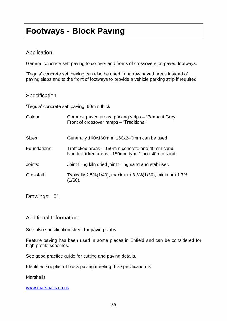
Footways - Block Paving
Application: General concrete sett paving to corners and fronts of crossovers on paved footways. ‘Tegula’ concrete sett paving can also be used in narrow paved areas instead of paving slabs and to the front of footways to provide a vehicle parking strip if required.
Specification: ‘Tegula’ concrete sett paving, 60mm thick Colour: Corners, paved areas, parking strips – ‘Pennant Grey’ Front of crossover ramps – ‘Traditional’ Sizes: Generally 160x160mm; 160x240mm can be used Foundations: Trafficked areas – 150mm concrete and 40mm sand Non trafficked areas - 150mm type 1 and 40mm sand Joints: Joint filing kiln dried joint filling sand and stabiliser. Crossfall: Typically 2.5%(1/40); maximum 3.3%(1/30), minimum 1.7% (1/60).
Drawings: 01
Additional Information:
See also specification sheet for paving slabs Feature paving has been used in some places in Enfield and can be considered for high profile schemes. See good practice guide for cutting and paving details. Identified supplier of block paving meeting this specification is Marshalls www.marshalls.co.uk

40
Reference Documents:
BS EN 1338 2003 Concrete paving blocks. Requirements and test methods.
BS 7533-2:2001 Pavements constructed with clay, natural stone or concrete pavers. HD 39/01 Volume 7, Section 2 Part 5 of Design Manual for Roads and Bridges.
Design guidance published by Interpave the Precast Concrete Paving & Kerb Association.
Version No; Date Issued / Updated: For Approval; March 2012

41
Footways - Tactile Paving
Application: Tactile paving for controlled and uncontrolled pedestrian crossings.
Specification: Tactile paving shall be blister type conforming with dimensions given in the DfT’s guidance on the use of tactile paving. Colour shall be grey on controlled crossings and buff on uncontrolled crossing points. On large radius curves the minimum depth of tactile paving may be reduced in order to avoid excessive depth of tactile paving overall. Slabs shall be 63mm thick with tactile features in accordance with Guidance on the use of Tactile Paving Surfaces, DETR 1998. Slabs only shall be used; vinyl or other ‘stick on’ materials shall not be used
Drawings: No standard detail; specific scheme layout plans required.
Refer to standard layouts in Guidance on the use of Tactile Paving Surfaces, DETR 1998
Additional Information: Design of tactile paving shall have due regard to the street scene whilst still providing sufficient information to those with sensory impairments.
Reference Documents: Guidance on the use of Tactile Paving Surfaces, DETR 1998
Version No; Date Issued / Updated: For Approval; March 2012

42
Intentionally Blank

43
Footways – Granite Kerb
Application: Kerbs to footways and central islands etc. Granite must be used where existing material is granite.
Detailed Specification: Upstand: Footways 125mm generally. Islands - 150mm Materials Granite – Good quality natural silver grey granite kerbs fine picked complying with the performance levels in European Standard BS EN 1343. Sizes to match existing; normally 300x200mm (flat) or 300x150mm (on edge) random lengths Foundation: 150mm concrete bed and haunch
Drawings: No standard detail
Additional Information: -
Reference Documents: BS EN 1343
Version No; Date Issued / Updated: For Approval; March 2012

44
Intentionally Blank

45
Footways – Concrete Kerb
Application: Kerbs to footways and central islands. Although concrete is acceptable in new construction, granite is preferred and must be used where existing material is granite.
Specification: Upstand: Footways 125mm generally. Islands - 150mm Materials Half battered smooth faced Sizes to match existing; Normal / residential – 235 x 125 mm Industrial areas – 305 x 150 mm Foundation: 150mm concrete bed and haunch
Drawings: No standard detail
Additional Information: -
Reference Documents: BS EN 1340 2003
Design guidance published by Interpave the Precast Concrete Paving & Kerb Association.
Version No; Date Issued / Updated: For Approval; March 2011

46
Intentionally Blank
47
Footways – Conservation Kerb
Application: Specific applications where the appearance of granite is required, but durability and strength of natural stone is not required i.e within speed tables.
Specification: Upstand: Footways 125mm generally. Islands - 150mm Materials Silver grey 145mm x 255mm Foundation: 150mm concrete bed and haunch
Drawings: No standard detail
Additional Information: Identified supplier of block paving meeting this specification is Marshalls www.marshalls.co.uk
Reference Documents: BS EN 1340 2003
Design guidance published by Interpave the Precast Concrete Paving & Kerb Association.
Version No; Date Issued / Updated: For Approval; March 2011

48
Intentionally Black

49
Footways – Chambers and Draw Pits
Application: Construction of chambers and draw pits within the footway or pedestrian areas.
Specification: Chambers: Chambers and draw pits in footways should be constructed of 225m brickwork, concrete or reinforced high density plastic with concrete backing. Plastic draw pits cannot be used on TfL signal installations. Their use has been removed from TfL’s Specification for the Installation of Traffic Signals and Associated Equipment. The detailed design of the draw pit will be to the plant / service provider’s specification. Minimum size of draw pit is generally 450 x 450mm, but in practice will be dependent on duct number, configuration, depth, cabling requirements and available space. Covers: Ductile iron covers are suitable for most applications. Inset covers are encouraged in town centres and for streetscape focal points, or where feature paving is used. Where such covers are used, tags with details of the plant / services within the chamber must be present.
Drawings: No standard detail
Additional Information: See good practice guide on footway paving for more information on chamber orientation and positioning. Alternatives: Subject to acceptance, chamber wall thickness may be reduced where necessitated by congestion with other underground services.
Design / Construction Reference Documents: -
Version No; Date Issued / Updated: For Approval; March 2012

50
Intentionally Blank

51
Footways - Domestic Crossover
Application: Crossovers serving a single domestic dwelling or shared drive between two properties. All off street parking must have a properly constructed vehicle crossover.
Specification: Within Paved Footways: Tegula blocks to ramp; colour –Traditional Fibre reinforced grey paving to rear. Foundation: 150mm concrete. Within Bituminous Macadam Footways: Bituminous macadam to same construction as footway
Drawings: standard detail in paved footway is shown on drawing No 1.
See L.B. Enfield Crossover Guidance Notes for layout and acceptable sizes
Additional Information: See specification sheets for paving and tegula concrete blocks A crossover will not be constructed unless a suitable parking area, meeting L.B. Enfield requirements is in place. Planning permission is required if parking areas are not constructed of impermeable material or cannot drain to soft landscaping and for crossovers on classified roads.
Reference Documents: L.B. Enfield Footway Crossover Application Form and Guidance Notes.
Version No; Date Issued / Updated: For Approval; March 2012

52
Intentionally Blank

53
Footways - Heavy Duty Crossover
Application: Crossovers serving more than a single residential property (or duel shared driveway) or commercial premises.
Specification: Standard Specification: 250mm thick C20 mesh reinforced concrete, 25mm HRA wearing course where crossover will be permanent. or 200mm type1, 200mm DBM roadbase, 60mm DBM basecourse, 40mm DBM wearing course. Alternative surfacing treatments to suit development streetscape objectives should be discussed with Highway Services.
Drawings: No standard detail
Additional Information: -
Reference Documents: -
Version No; Date Issued / Updated: For Approval; March 2011

54
Intentionally Blank

55
Carriageways - Flexible Construction
Application: All carriageways in Enfield, unless alternative construction specifically specified. Approval must be obtained from the Highway Authority to proposed road construction and levels.
Specification: The required thickness of sub-base will be dependant on the quality and CBR value of the sub grade. The total thickness of bituminous road construction will be related to the number and type of vehicle for the category of road. General Road categories to be considered: Principal Road Residential Road Industrial Road The foundation is to be designed in accordance with interim advice note 73/06 (Draft HD25) Design Guidance for Road Pavement Foundations. Asphalt shall be in accordance with BS EN 13108 Generally surfacing shall be 55/10 Design Mix HRA, 14mm chippings.
Drawings: No standard detail
Additional Information: Alternative Material: Other forms of asphalt or bituminous material such as modified asphalts will be considered for special applications. Other forms of carriageway construction to meet specific street scene objectives will be considered as replacement for binder and surfacing courses, but must be discussed with Highway Services.

56
Reference Documents: BS EN 13108 Interim advice note 73/06 (Draft HD25) Design Guidance for Road Pavement Foundations.
Version No; Date Issued / Updated: For Approval; March 2012

57
Carriageways – High Friction Surfacing
Application: Surfacing to be applied where specified at critical locations to increase the skid resistance of the road surface to vehicles.
Specification: Treatments may be hot applied or cold applied calcined bauxite. Colour – grey unless specifically instructed otherwise. Calcined bauxite. Minimum PSV 65 Cold applied treatment – resin formulations to be approved prior to use. Skid resistant surfacing should have a minimum skid resistance value (SRV) 70. All materials to be HAPAS approved
Standard Drawing: No standard detail
Additional Information: -
Reference Documents: HD 37/99 High Friction Surfacing HD 28/04 Skid Resistance
Version No; Date Issued / Updated: For Approval; March 2012

58
Intentionally Blank

59
Carriageways – Traffic Calming Measures
Application: Traffic calming
Specification: A variety of traffic calming features may be considered. Vertical deflections such as speed tables and cushions are preferred to humps. Speed tables shall be constructed in asphalt to match the carriageway surfacing and shall not be coloured. Speed cushions shall either be in asphalt or preformed rubber on sound road surface and foundation. Profiles shall be in accordance with the Traffic Calming Regulations.
Drawings: No standard detail
Additional Information: No vertical deflections shall be installed on Enfield’s Emergency Services network (see network Management Plan) A suitable supplier meeting the specification for rubber speed cushions is Rediweld Rubber and Plastics, rediweld.co.uk.
Reference Documents: The Highways (Traffic Calming) Regulations 1999 The Highways (Road Hump) Regulations 1999 Traffic Calming Measures for Buses. TfL Bus Priority Team Advice Note BP2/05.
Version No: Date Issued / Updated: For Approval; March 2012

60
Intentionally Blank

61
Signs – Non Illuminated Traffic Signs
Application: All traffic signs and other signs to traffic sign standard. See separate specification for street name plates.
Specification: Signs shall be manufactured from 11 swg / 3mm aluminium. Minimum two channels to reverse of sign riveted to signs at minimum 150mm centres. All signs to have rounded corners. Parking signs and non traffic signs – non reflective Class Ref 1 Engineer Grade General traffic sign application – Class Ref 2 High Intensity Prismatic At accident hotspots – DG3
Sign manufacturers to comply with BSI sector scheme 9a (manufacture) All traffic signs shall comply with the Traffic Signs Regulations and General Directions.
Standard Drawing: No standard detail
Additional Information: Alternative Types: In specific circumstances signs manufactured from glass reinforced polyester instead of aluminium will be allowed. Yellow backing to signs are only to be used in specialist circumstances requiring this additional safety feature. Fixing of Signs to Lamp Columns: The fixing of signs to columns is encouraged as it helps to reduce the number of posts installed. However, lighting columns are not designed for lateral loading and the wind resistance offered by even a modest size sign can increase lateral loading on a column considerably, which it may not be designed to take. The Street Lighting PFI

62
contractor is responsible for the maintenance of all street lighting in the borough and any proposal to fix signs to columns must be undertaken with approval of the PFI contractor and must be done in such a way so as not to damage any protective paint coatings. The fixed sign will need to be accrued on to xxx data base for asset management purposes.
Reference Documents: BS EN 12899-1 Road traffic signs and internally illuminated bollards. Specification for retroreflective and non-retroreflective signs
Traffic Signs General Directions Traffic Signs Manual
Version No; Date Issued / Updated: For Approval; March 2012
63
Signs – Illuminated Traffic Signs
Application: All illuminated traffic signs and other illuminated signs to traffic sign standard and their associated electrical works.
Specification: All street lighting and associated electrical works shall comply with L.B. Enfield’s specification for street lighting under its PFI contract and meet the requirements laid down by the PFI Contractor, ETDE Infrastructure Ltd. See separate street lightning developer’s guidance for detailed specification. All traffic signs shall comply with the Traffic Signs Regulations and General Directions.
Standard Drawing: No standard detail
Additional Information: Fixing of Signs to Lamp Columns: The fixing of signs to columns is encouraged as it helps to reduce the number of posts installed. However, lighting columns are not designed for lateral loading and the wind resistance offered by even a modest size sign can increase lateral loading on a column considerably, which it may not be designed to take. The Street Lighting PFI contractor is responsible for the maintenance of all street lighting in the borough and any proposal to fix signs to columns must be undertaken with approval of the PFI contractor and must be done in such a way so as not to damage any protective paint coatings.
Reference Documents: BS EN 12899-1 Road traffic signs and internally illuminated bollards. Specification for retroreflective and non-retroreflective signs
Traffic Signs General Directions Traffic Signs Manual
Version No; Date Issued / Updated: For Approval; March 2012

64
Intentionally Blank

65
Signs – Illuminated and Rebound Bollards
Application: All locations where an illuminated bollard is required.
Specification: All street lighting and associated electrical works shall comply with L.B. Enfield’s specification for street lighting under its PFI contract and meet the requirements laid down by the PFI Contractor,. See separate street lightning developer’s guidance for detailed specification. All traffic signs shall comply with the Traffic Signs Regulations and General Directions. L.B. Enfield has approval to use of non illuminated rebounded type bollards instead of traditional ‘haldo’ type bollards in specific circumstances as follows: -
On a central refuge or in the mouth of a side road (but backed up by a conventional illuminated sign to dia 610 or 611 mounted on a central island column). On a central refuge at the mouth of a side road containing traffic signals. On a central refuge at a zebra crossing (with central island column and two flashing beacons) On a build out (keep right sign) (with other priority working signage)
In all other circumstances base lit ‘haldo’ bollards shall be used. The use of a specific style of bollard for enhanced streetscape objectives needs to be approved in consultation with Highway Services.
Standard Drawing: No standard drawing
Additional Information: In furtherance of L.B. Enfield’s policy to minimise the amount of street furniture the need for the provision of keep left bollards where the direction of travel is obvious to a driver should be considered.

66
Reference Documents: Traffic Signs Regulations and General Directions Traffic Signs Manual
Version No; Date Issued / Updated: For Approval; March 2012

67
Signs - Pedestrian Direction Signs
(Town Centres)
Application: All pedestrian signs in town centres and on identified links between town centres. L.B. Enfield is promoting a pedestrian and cycling signing system based on the ‘Legible London’ format.
Specification: No specific format or specification has been adopted in Enfield and signs should be in keeping with the townscape or conservation area in which they are situated or match an existing format which has been adopted. However, L.B. Enfield is promoting a pedestrian and cycling signing system based on the ‘Legible London’ format and compliance with this signing strategy and format is likely to apply to a number of locations across Enfield and signs will be required to meet this format and specification. All pedestrian signs shall comply with the Traffic Signs Regulations and General Directions.
Standard Drawing: No standard drawing
Additional Information: -
Reference Documents: BS EN 12899-1 Road traffic signs and internally illuminated bollards. Specification for retroreflective and non-retroreflective signs
Traffic Signs General Directions Traffic Signs Manual Legible London Guidance documents
Version No; Date Issued / Updated: For Approval; March 2012

68
Intentionally Blank

69
Signs - Pedestrian Direction Signs
(Footpaths, Bridleways and
Public Rights of Way)
Application: All pedestrian signs on urban and rural footpaths, bridleways and public rights of way. L.B. Enfield is promoting a pedestrian and cycling signing system based on the ‘Legible London’ format and this may apply to some footpath locations.
Specification: Urban footpaths and rural footpaths where they intersect with the road network - Metal Signs: Material: 11 swg / 3mm aluminium. Reflective Class Ref 1 Engineer Grade Sign manufacturers to comply with BSI sector scheme 9a (manufacture) All pedestrian signs at highway intersections shall comply with the Traffic Signs Regulations and General Directions. Posts – standard circular steel, black finish. Rural footpaths - Timber Signs: Material: Hardwood Post size: 140mmm x 140mm Legend on arms and post to be machined into timber. Sponsorship information on disc to be inserted in routed out rebates on post. Environmentally sound practices should be followed and timber sourced from commercially managed, recognised, sustainable, renewable and ethically managed or approved forests such as those under the FSC scheme.

70
Way Markers and Posts: Way markers to be in accordance with the Traffic Signs Regulations and General Directions. Material plastic or alluminium discs. Posts: 1.5m, 100mm x 100mm tantalised timber with pointed (four way weathered) top cut to an angle of 45°.
Standard Drawings: No standard detail
Additional Information: Alternative Types: In specific circumstances aluminium signs may be manufactured from glass reinforced polyester. ‘Legible London’ type signs may be appropriate. Identified supplier, meeting this specification for timber signs is Woodscape Ltd www.woodscape.co.uk
Design Reference Documents: BS EN 12899-1 Road traffic signs and internally illuminated bollards. Specification for retroreflective and non-retroreflective signs
Traffic Signs Regulations and General Directions Legible London guidance documents
Version No: Date Issued / Updated: For Approval; March 2012

71
Signs – Street Nameplates
Application: All street nameplates.
Specification: Sign Format All street nameplates to be of standard format displaying Enfield heraldic beast and ‘Enfield’, post code. On all no through roads the street nameplate is to incorporate a sign to diag 816.1 of the Traffic Signs Regulations and General Directions on the right hand side of the plate. Sign to be full height of plate. All lettering to be uppercase (capitals) Lettering for street name; Black Kindersley, 89mm high. Full text to be used, i.e. no abbreviations Lettering for postcode: Red Kindersley 50mm high following road name. Enfield Heraldic Beast facing left on left hand side, screen printed red. Wording ‘ENFIELD’ below beast in red Ariel italics Colour Specification Red for beast logo, ‘ENFIELD’ and post code – PANTONE 485. When printing in cmyk colours - c0 m97 y100 k0 Black for street name and border - 1005 black cmyk c0 m0 y0 k100.
72
Materials and Finish Nameplates to be white non reflective background with 12 mm black border and rounded corners Conservation Areas: Die pressed 11 swg aluminium. Street name only to be embossed Other areas: 2.5mm polycarbonate / Perspex. Sizes Plate depth – Single line of text 200mm. Two lines of text 300mm. Maximum plate length is 1500mm. Fixing Street nameplate shall be either fixed to a backing board free standing on two posts or fixed directly to abutting property walls. Free Standing Signs Backing Boards: Backing boards and posts shall be supplied factory fixed to signs by sign manufacturer. Backing boards to be 30mm thick recycled black plastic and exact shape of street nameplate with radius corners. Sign securely fixed to backing board with glue and maximum 8 tamper proof screws through centre of black boarder capped with black coloured PVC caps. Post supports: 2 No, 1.35 thick, 75mm x 75mm recycled plastic with pyramid tops BACK MOUNTED to sign and backing board with 2 No. M8 s/s bolts per post. Bolt head and nut recessed into plastic and capped. Sign, backing board and posts to be installed in ground with 50mm concrete bed and 150mm concrete surround.

73
Signs fixed Directly to Walls Signs to be predrilled by sign manufacturer with 8 holes through centre of black boarder. Fixing on site to be with appropriate screws and plugs for material and condition. Screws to be capped with black coloured PVC caps. Mounting Heights and Location Preference is for street nameplates to be mounted directly on to adjoining properties if possible, thus reducing amount of street furniture within footway. If this is not possible then they should be mounted at the back of footway, although it is sometime necessary to place them in grass verges for visibility. Suitable locations need to be determined on an individual site basis. Mounting height to be determined in relation to local features, but generally between 550mm and 2000mm.
Standard Drawings: 02
Additional Information: Only standard street nameplates conforming to this specification are to be used throughout the borough. Suitable supplier meeting this specification is Signway Supplies (Datchet) Limited.
www.signway.co.uk
Reference Documents:
-
Version No; Date Issued / Updated: For Approval; March 2012

74
Intentionally Blank

75
Signs - Standard Sign Posts and Brackets
(Non Illuminated Signs)
Application: Sign posts for urban streets and roads subject to speed limits less than 30mph
Specification: Posts - circular hollow section of appropriate diameter to meet loading requirements, Minimum diameter 76mm. Black colour, plastic coated or painted over galvanised finish, unless a specific finish is being specified to meet street scene objectives. All posts shall have end caps Extension post and offset brackets must be manufactured to specific requirements and also finished in black. Planting depth and foundation requirements are dependent on sign size and loading. Wind loading of 1.2KN/m2. For exposed locations or where funnelling may occur a wind loading of 1.5KN/m2 should be applied.
Standard Drawings: No standard detail
Additional Information: For large signs requiring two posts, the use of cantilever signs on single posts should be used. For protective coatings and finishes see separate specification sheet.
Reference Documents: BS EN 12899-1:2007 Fixed, vertical road traffic signs. Fixed signs. Sign Structures Guide, Institute of Highway Engineers, Sept 2010.
Version No; Date Issued / Updated: For Approval ; March 2012

76
Intentionally Blank

77
Signs - Standard Sign Posts and Brackets
(Illuminated Signs)
Application: Sign posts for illuminated signs.
Specification: Posts - circular hollow section, wide bottom, of appropriate diameter to meet loading requirements, Minimum diameter 76mm, base diameter 140mm with tamper proof inspection hatch. Black colour, painted over galvanised finish. All posts shall have end caps Extension post and offset brackets must be manufactured to specific requirements and also finished in black. Planting depth and foundation requirements are dependent on sign size and loading. Wind loading of 1.2KN/m2. For exposed locations or where funnelling may occur a wind loading of 1.5KN/m2 should be applied. All illuminated sign posts shall comply with L.B. Enfield’s specification for street lighting under its PFI contract and meet the requirements laid down by the PFI Contractor, ETDE Infrastructure Ltd. See separate street lightning developer’s guidance for detailed specification.
Standard Drawings: No standard detail
Additional Information: For large signs requiring two posts, the use of cantilever signs on single posts should be used. For protective coatings and finishes see separate specification sheet.
Reference Documents: BS EN 12899-1:2007 Fixed, vertical road traffic signs. Fixed signs. BS ES ISO 146:1999 Hot dipped galvanising
Version No; Date Issued / Updated: For Approval; March 2012

78
Intentionally Blank

79
Signs - Passive Safety Posts
(Non Illuminated Signs)
Application: Sign posts for rural road and roads subject to speed limits greater than 30mph
Specification: Posts - circular, not lattice construction Posts to be frangible, passive safety posts. Class: 100 NE Posts shall be of appropriate diameter to meet loading requirements.
Material - steel, fibre glass composite, carbon fibre composite or aluminium. Colour - Black. All posts shall have end caps Post installation to be in accordance with manufacturer’s directions.
Standard Drawings: No standard detail
Additional Information: Suitable supplier meeting this specification is ASD Metal Services www.asdsignproducts.co.uk
Reference Documents: BS EN 12767:2007 Passive safety of support structures for road equipment. Requirements, classification and test methods. BS EN 12899-1:2007 Fixed, vertical road traffic signs. Fixed signs.

80
TD 89/08 Use of passively safe signposts, lighting columns and traffic signal posts to BS EN 12767: 2007. Sign Structures Guide, Institute of Highway Engineers, Sept 2010.
Version No; Date Issued / Updated: For Approval; March 2012

81
Signs - Carriageway Markings
Application: Carriageway and other markings on the highway
Specification: Thermoplastic shall be used for all new lining. Paint to be used for all refreshes. Road markings should be reflectorised with solid glass beads, conforming to BSEN1423. Narrow primrose yellow lines to be used in all conservation areas and on non principal roads. All markings shall comply with the Traffic Signs Regulations and General Directions and Traffic Signs Manual, where applicable to traffic direction. In addition to meeting the requirements of the Specification for Highway Works, road markings shall also comply with the performance requirements of BSEN1871 and BSEN1436. Road studs shall comply with BS873 and be depressible, self wiping, long type, either metallic or non metallic.
Standard Drawings: No standard detail
Additional Information: -
Reference Documents: Traffic Signs General Directions Traffic Signs Manual BSEN1872 and BSEN1436
Version No; Date Issued / Updated: For Approval; March 2011

82
Intentionally Blank

83
Street Furniture – Cast Iron Bollard
(Footways)
Application: Standard bollard for footway protection; most applications.
Specification: Style: Round, fluted sides with pillar box top ‘Doric’ style. Version 1 – fully fluted to top. Version 2 - smooth faced upper section for the fitting of red / white reflective bands. Material: cast iron or polyurethane elastomer with steel core, dependant upon vulnerability and application. Colour: black. Foundation: 150mm concrete bed and surround. Base plate fixing only to be used where deemed necessary. Anchor and rod fixing where deemed necessary.
Drawings: 03
Additional Information: Application The use of bollards should be carefully considered, as there use is contrary to the Council’s general policy to minimise street furniture. Other measures to deter or prevent vehicle overrun should be considered.

84
Alternative Types: Other types of bollard, such as bell bollards, may be acceptable where specialist protection is required. No other ‘style of bollard to be used for general purposes unless part of approved specific street scene theme. Lighter and heavy duty formats of the Doric bollard may be used in appropriate applications as well as adapted forms for supply pillars. Suppliers meeting this specification are: Version 1 cast iron - Doric 520 as supplied by Furnitubes International Ltd www.furnitubes.com Version 1 polyurethane elastomer with steel core – DO 0520 as supplied by Furnitubes International Ltd www.furnitubes.com Version 2 cast iron – BX1520 Blackburn as supplied by Broxap Ltd www.broxap.com
Design Reference Documents: -
Version No; Date Issued / Updated: For Approval; March 2012

85
Street Furniture – Passive Safety Bollard
(Footways)
Application: Standard bollard for footway protection where a passive safety product is required.
Specification: Style: Round, 150mm diameter plain bollard. smooth faced upper section for the fitting of red / white reflective bands. Material: Stabilised medium density polyethylene Colour: Black. Foundation: Standard fixing, surface (bolt down) fixing where insufficient depth for standard fixing or socket fixing where occasional removal is required.
Drawings: No standard detail
Additional Information: Application The use of bollards should be carefully considered, as there use is contrary to the Council’s general policy to minimise street furniture. Other measures to deter or prevent vehicle overrun should be considered.
The standard bollard for most applications is the ‘doric’ style bollard, detailed on previous sheet. This bollard should only be used where a passive safety product is required.

86
Alternative Types: Sign head versions may be used where signage is required. Suppliers meeting this specification are: Leafield Environmental – Heratige 150 www.leafieldhighway.com Glasdon – Neapolitan 150 www.glasdon.com
Design Reference Documents: -
Version No; Date Issued / Updated: For Approval; March 2012

87
Street Furniture – Timber Bollard
(Grass Verges & Shrub Beds)
Application: Standard bollard for protection of grass verges and other soft landscaped areas.
Additional Information: Provision: The use of bollards should be carefully considered as their use is contrary to the Council’s general policy to reduce and minimise street furniture. Other measures to deter or prevent vehicle overrun should be considered such as double height kerb. Environmentally sound practices should be followed and timber sourced from commercially managed, recognised, sustainable, renewable and ethically managed or approved forests such as those under the FSC scheme. Suitable supplier meeting this specification is: York bollard as supplied by Heritage Timber, www.heritagetimber.co.uk
Specification: Style: 175mm square with pointed (four way weathered) top cut to an angle of 45°. Material: Timber – oak or other acceptable hardwood. Treated softwood is not acceptable. Overall length 1200mm – 800mm above ground; 400mm below ground Foundation: 150mm concrete bed and surround
Standard Drawings: No standard detail

88
Design Reference Documents: -
Version No and Date Issued / Updated: For Approval; March 2012

89
Street Furniture – Seat (Timber)
Application: All timber construction seat to be used in green open spaces and similar areas within conservation areas.
Standard Drawing: 04
Additional Information: Provision: The provision of seats should be carefully considered, as they can be a gathering place for anti social behaviour. Seats will only be installed at the discretion of the Council, where there is an identified need. Alternative Types: Other types of timber seat will not be considered as an alternative to this type.
Specification: Material: Iroko hardwood, oiled finish. Style: Five slated seat, vertical slated back, curved back rail and front spandrels to ends Fixing: galvanised steel straps to bottom side rail embedded in concrete foundation.

90
Memorial Seats:
Where the seat is designated a memorial seat a small brass plaque can be fixed in accordance with the specification for memorial plaques.
Timber Source: Environmentally sound practices should be followed and timber sourced from commercially managed, recognised, sustainable, renewable and ethically managed or approved forests such as those under the FSC scheme. Identified supplier of timber seat meeting this specification is BX17 4021 Grosvenor seat supplied by Broxap Limited www.broxap.com
Reference Documents: -
Version No; Date Issued / Updated: For Approval; March 2012

91
Street Furniture – Seat (Metal)
Application: Traditional style slatted seat with metal ends to be used in urban areas and town centres.
Standard Drawing: 05
Additional Information: Provision: The provision of seats should be carefully considered, as they can be a gathering place for anti social behaviour. Seats will only be installed at the discretion of the Council where there is an identified need. Alternative Types: Other types of seat may be considered for specific locations and projects where the use of this standard seat is not appropriate.
Specification:
Slats –
Recycle Recycled material, ‘Environpol’ or similar; colour black End Supports – Recycled aluminum, ‘Armortec’ coated or similar; colour black Pattern – see drawing Enfield beast and ‘London Borough of Enfield’ to be incorporated in seat end Frame - Mild steel, ‘Armortec’ coated or similar; colour black
Fixing: Bolted to surface.

92
Memorial Seats: Where the seat is designated a memorial seat a small brass plaque can be fixed in accordance with the specification for memorial plaques. Identified supplier of metal seat meeting this specification is the ‘Stanford’ supplied by Glasdon Ltd. www.glasdon.com
Reference Documents: -
Version No; Date Issued / Updated: For Approval; March 2012

93
Street Furniture – Pedestrian Guard Railing
Application: All Pedestrian guard railing
Specification: Steel ‘visi rail’ with rod arrangement according to specific site requirements. Foundation: 150mm bed and surround to all posts Colour - Black painted over galvanised finish, or powder coated.
Drawings: No standard detail
Additional Information: Provision: The use of pedestrian guard railing should be carefully considered, as its use is contrary to the Council’s general policy to reduce and minimise street furniture. Formal risk assessments to determine whether guard railing is required using either the DfT or TfL methods should be undertaken. Alternative Types: In some areas of Enfield and enhanced more decorative type of PGR has been used and this should be matched.
Reference Documents: Local Transport Note 2/09 – Pedestrian Guard Railing Transport for London Guardrail Risk Assessment Form Guidance Note
Version No; Date Issued / Updated: For Approval; March 2012

94
Intentionally Blank

95
Street Furniture – Cycle Stands
Application: Provision of cycle parking facilities.
Specification: Style: Sheffield type hoop with mid point tapper rail meeting DDA requirements. Material: Polyurethane elastomer (with steel core) or stainless steel where appropriate. Overall length 700mm; height 875mm above ground, 300mm below ground Foundation: 150mm concrete bed and surround
Standard Drawings: No standard detail
Additional Information: Provision: Although cycle parking demand both actual and latent should be met, their provision and siting should be carefully considered as they can significantly add to the amount of street furniture on street, visual intrusion and obstruction. Alternative Provision: Specialists cycle stand fixed directly to street furniture. Cycle stands should be located and spaced 1000mm to 1200mm apart to allow for cycle parking on both sides of the stand. Identified supplier of Sheffield type cycle stands meeting this specification is: Furnitubes, www.furnitubes.com Polyurethane elastomer ‘Hammersmith’ HAM70 Stainless Steel ZEN 650 BP

96
Identified supplier of street furniture cycle bracket is Cyclehoop Ltd www.cyclehoop.com
Reference Documents: Local Transport Note 2/08 – Cycle Infrastructure Design
Version No; Date Issued / Updated: For Approval; March 2012

97
Street Furniture – Protection and Finishes
Application: Protection and finish to all street furniture. Paint specification for highway structures and specific drainage applications to be agreed with Highway Services.
Specification: The colour for all street furniture shall be black, unless otherwise specified for specific streetscape purposes. Pedestrian Guard Railing: Hot dipped galvanised and either powder coated or painted. Posts:
Hot dipped galvanised and painted Powder coated 0.4mm extruded plastic coating
Bollards: Cast iron – manufacturer applied primer or on site applied metal chromate primer. Paint finish to consist of - Preparation of surface by wire brush, wash or galvanise treatment if applicable Undercoat / basecoat (2 coats) Top coat – Hammerite paint manufactured by ICI or equivalent No painting to be carried out during extremes of temperature of in wet conditions.
Drawings: No standard detail

98
Additional Information: Other finishes such as stainless steel would be considered to meet specific streetscape objectives.
Reference Documents: Hot dipped galvanising to BS EN ISO1461;1999 Delux Trade Technical Advice Centre – Tel: 0870 2421100
Version No; Date Issued / Updated: For Approval; March 2012

99
Soft Landscaping – Grass Areas
Application: Grass seeded or turfed verges and open spaces.
Specification:
Grass seed: Grass seed shall comply with BS 4428 Grass seeding shall be sown during the period 1st September to 30th November, or 1st March to 31st May. The upper 50mm of soil shall be cultivated to a fine tilth in order to receive seeding. Mixture Type A – General amenity grass mix for verges and highway areas
35% Chopin Strong creeping red fescue 25% Barona hard fescue 20% Bardur Perennial ryegrass 12.5% bartender Smooth stalked meadow grass 5% Highland Browntop bent 2.5% Crusader White clover
Mixture Type B – Wild Flora Mix for conservation grass
20% British Seed Houses WF3 80% A18 Motorways/Road Verges mix.
Sowing rates
New areas 35g / m2 Top dressing 15g / m2 Wildflower mix 5g / m2
Turf: Turfing shall be carried out in accordance with BS 3969 and BS 4428 Turf type: Rolawn Medallion or equivalent

100
Turf laid at greater than 20 degree to the horizontal to be secured with propriety wire pins. Maintenance of new grass areas: Protection and water shall be provided as necessary to permit successful germination and establishment. Establishment cuts:
Seeded areas – 4 Turfed areas - 2 Cuts to be by cylinder mower and all cuttings to be removed.
Drawings: No standard detail
Additional Information: See good practice guidance.
Reference Documents: BS 4428 BS-3882
Version No; Date Issued / Updated: For Approval 1; March 2012

101
Soft Landscaping – Tree Species
Application: Tree species suitable for highway environments.
Specification: The type and variety of tree suitable and appropriate for highway purposes will be different depending on the location. Choice will need to take into account existing planting, local architecture and space. Choice of species should be discussed with the Council’s Highways Arboricultural Officer. Typical tree species for highway applications are given in the schedule under additional information.
Drawings: No standard detail
Additional Information: See good practice information on choice of tree type.
Schedule of Trees Suitable for Highway Purposes:
The trees listed overleaf cover suitability for a range of different highway situations, some will suit large grass areas and some will suit narrow pavement areas.

102
Acer campestre ' Queen Elizabeth' Ostrya carpinifolia
Acer campestre 'Elegant' Paulownia tomentosa
Acer campestre 'Elsrijk' Platinus x hispanica
Acer campestre 'Louisa Red Shine' Populus nigra
Acer platanoides 'Columnare' Populus tremula
Acer platanoides 'Princeton Gold' Prunus amanogawa
Acer rubrum Prunus avium 'Plena'
Aesculus carnea 'Briotii' Prunus cerasifera 'Nigra'
Aesculus hippocastanum Prunus padus 'Purple Queen'
Alnus cordata Prunus padus
Alnus glutinosa Prunus 'Pandora'
Amelanchier lamarkii Prunus 'Pink Perfection'
Arbutus unedo Prunus sargentii
Betula pendula Prunus sargentii 'Rancho'
Betula pendula 'Fastigiata' Prunus serrula 'Fructosa Globosa'
Betula utilis Prunus shimidsu sakura
Betula utulis jacuemontii 'Doorenbos' Prunus 'Tai Haku'
Carpinus betulus 'Pyramidalis' Prunus x subhirtella 'Autumnalis Rosea' Cataegus monogyna Pseudoplatanus spaethii
Crataegus laevigata 'Paul's Scarlet' Pyrus calleryana 'Chanticleer'
Crataegus monogyna 'Stricta' Pyrus calleryana 'Redspire'
Fagus sylvatica Quercus coccinia
Fagus sylvatica'Purpurea' Quercus ilex
Fagus sylvatica'Riversii' Quercus robur
Fraxinus excelsior 'Ornus' Quercus rubra
Fraxinus excelsior Salix alba
Ginko biloba Salix tristis
Gleditsia triacanthus Sorbus auccuparia 'Cardinal Royal'
Juglans regia Sorbus auccuparia 'Golden Wonder'
Liquidamber styraciflua Sorbus auccuparia 'Sheerwater Seedling' Liriodendrum tulipifera Sorbus torminalis
Malus 'Donald Wijman' Tilia cordata 'Greenspire'
Malus 'Rudolph'
Reference Documents -
Version; Date Issued / Updated: For Approval; March 2012

103
Soft Landscaping – Tree Protection
Application: All sub soil features and above ground support and protection to highway trees.
Specification:
Tree Protection and Surrounds:
Tree grills may be a trip hazard if not installed and maintained correctly. They also trap litter. The council policy is to avoid the use of tree grills and to use an open textured resin bound gravel instead. - ????? Tom’s Tree Ties Super Strimmer Guard shall be used to protect all trees planted in grass areas. Root barriers:
Root barriers are a geo-textile membrane (a synthetic woven fabric through which tree roots are not able to penetrate and used to protect paved areas from tree roots particular if pavements are built adjacent to shallow rooted trees. The following root barriers shall be used Individual trees in paved areas – Greenleaf Root Director Trees in planted areas adjacent to paved areas or structures – Greenleaf Re-Root 1000 Trees adjacent to deep services or utility company plant - Greenleaf Re-Root 2000 Staking:
Stakes are used to stabilise trees until they are established and can support themselves. Low stakes are preferred because they allow the trunk to flex in the wind with promotes the development of a strong trunk and root system.
Staking of extra heavy and heavy standard trees shall include the Playtpus Guy fixing system G2 unless otherwise directed. The securing of semi mature, extra heavy standard and heavy standard trees shall include the use of Platpus tree anchors dead man system ref No RF2RDM, unless otherwise directed. Irrigation:

104
Adequate water must be established during the trees early years. An irrigation tube should be installed to assist with watering. All trees shall be watered in as listed in the following table.
Tree Quantity (litres)
Whip size 10
Light standard 25
Standard 50
Heavy standard 105
Extra heavy standard 150
Semi mature 200
Irrigation systems shall be installed as listed in the following table
Size (Length) Irrigation Product
Standard – Heavy Standard – 3.0m
Greenleaf Root Rain Urban RRURB1
Extra Heavy Standard – Advanced Nursery Stock – 5.0m
Greenleaf Root Rain Urban RRURB2
Semi Mature – 8.0m Greenleaf Root Rain Urban RRURB3
Soils and Backfill: The back fill mixture for tree pits shall incorporate Broad leaf P4 at a rate in accordance with the manufacturer’s recommendations.
Drawings: 06 and 07
Additional Information:
See good practice guidance.
Reference Documents: -
Version No; Date Issued / Updated: For Approval; March 2011

105
Soft Landscaping – Shrub Beds and
Hedges
Application: Shrub beds in verges and open spaces and shrubs grown as hedges.
Specification: Shrub Beds: Planting schedule to be agreed by Highway Services. Generally 60% shrubs, 40% ground cover. Shrubs – 3 plants/m2; groundcover – 5 plants/m2; roses – 4 plants/m2 Grafted stock shall not be used. Native plants shall be supplied with a province certificate. All canes, labels and ties shall be removed immediately after planting. Climbing plants shall be secured to supports. Compost in accordance with PAS100 shall be applied to all planting areas. Broadleaf P4 shall be applied at the rate of 100g/m2. Bare rootstock shall only be planted after leaf fall or 1st November (which ever is later and before 31st March or bud break (which ever is later). Containerised plants planted during March to August shall be planted 25mm below nursery soil mark and a shallow depression formed to retain moisture. All planting trenches shall be backfilled prior to planting Shrubs should have a minimum topsoil depth of 450mm (18”). Foundations or hard ground should be broken below that depth to ensure free drainage. All planted areas shall be cultivated prior to planting. All beds are to be irrigated following planting to a depth of 50mm. Excavated material form planting holes shall be removed from site. On completion of planting the bed shall be lightly forked or hoed trough to remove any footprints and to leave a neat and tidy finish.

106
All shrub beds and planted areas shall be maintained by hand weeding during the establishment period. A total herbicide should be applied to ensure that problem perennial weeds such as couch grass are eradicated. It is almost impossible to remove such weeds after planting. A 10mm pea shingle drainage channel, 100mm x 100mm x 200mm deep shall be installed in new soft landscaping areas, against hard surface area, to assist in water retention and alleviate ponding and runoff. Hedges: Native hedge mix. Increase the proportion of shade tolerant species in shaded conditions Ornamental hedges - Other species may be suitable. Informal flowering species may also be used.
Drainage: A 10mm pea shingle drainage channel, 100mm x 100mm x 200mm deep shall be installed in new soft landscaping areas, against hard surface area, to assist in water retention and alleviate ponding and runoff.
Drawings: No standard detail
Additional Information: See good practice guidance. Planters: Planters and containers provide for planting in areas too restricted to accommodate beds. Enfield does not have a standard design / specification for planters. Planters should be of durable material, low maintenance and in keeping with its location and street scene.
Reference Documents: -
Version No; Date Issued / Updated: For Approval; March 2012

107
Soft Landscaping – Bulb Planting
Application: Bulb planting in verges and open spaces.
Specification:
Bulb planting schedule to be agreed by Highway Services. Typical planting density of bulbs shall be :
Bluebell 150/m2 Crocus 100/m2 Tulip (large) 50/m2 Narcissus (large) 60/m2 Small narcissus / tulip etc 60/m2
Planting depths of bulbs shall be in accordance with Royal Horticultural Society guidelines: 2-3 times the depth of the bulb.
Drawings: No standard detail
Additional Information: See good practice guidance.
Reference Documents: -
Version No; Date Issued / Updated: For Approval; March 2012

108
Intentionally Blank

109
Soft Landscaping – Topsoil and Mulches
Application: Topsoil and mulches for shrub beds and grass areas.
Specification:
Top soil shall be to BS-3882 (General Purpose Grade) with a medium loam texture within the range of 6.5 – 7.5 pH. The soil should be reasonably free of stones with a maximum stone size of 5mm in any dimension. Organic matter should not be less 4%, free of weed seeds, roots of perennial weeds, stick, subsoil and foreign matter. Imported peat shall not be used. Top soil shall be spread in layers not exceeding 150mm thick. Each layer shall be firmed before spreading the next. The upper 50mm of soil shall be cultivated to a fine tilth where seeds are to be sown. The use of tracked vehicles for laying is not permitted. Timber mulches shall be 100% organic and be from sustainable forests. Mulch sheets and mats shall be either photodegradable such as polythene, spunbound polypropylene or woven polypropylene, or biodegradable such as jute or hessian. Mulch mats and sheet mulches and shall be fixed with proprietary wire pegs.
Drawings: No standard detail
Additional Information:
See good practice guidance.
Reference Documents: BS 3882; 2007
Version No; Date Issued / Updated: For Consultation; March 2012

110
Intentionally Blank

111
Street Lighting – Lamp Columns & Lanterns
Application: All street lighting and associated electrical works.
Specification: All street lighting and associated electrical works shall comply with L.B. Enfield’s specification for street lighting under its PFI contract and meet the requirements laid down by the PFI Contractor, ETDE Infrastructure Ltd. See separate street lightning developer’s guidance for detailed specification. The lighting design will be in accordance with BS 5489 - 1 – 2003 Road Lighting Design. All lighting designs are required to meet the adoptable standards for the borough, either, S2, S1, ME2 or CE2 or others as detailed. Generally lighting columns shall be sited at the back of footways or verges and against the property line on property boundaries or building lines. In town centres, lanterns mounted on buildings is encouraged where routine maintenance can be easily accommodated.
The lighting column manufacturer shall be registered with and certified by either ‘BSI Quality Assurance Services’ or ‘Lloyds Registered Quality Assurance Limited’ for the manufacture, supply and verification of lighting columns under BSEN ISO 9002. All columns and brackets are to be galvanised and have further root protection. All columns and brackets are to be erected complete with a factory painted finish in black. Under the PFI contract and for a consistent approach across the borough two types of column and two types of lantern and column are specified – either plain standard or heritage style on designated routes.

112
Standard lanterns shall be WRTL arc. Heritage lanterns shall be HQI Lamps (Gladstone Lantern). Generally high pressure sodium lighting to be used except in town centres where ceramic metal halide white light is to be used. Light source shall have a minimum Ra value of 20 and should white light be used it shall have a minimum Ra of 80. Calculation shall be based on a maintenance factor determined by an appropriate pollution factor and the manufactures lumen output specification.
Drawings: Refer to standard details within separate street lighting developer’s
guidance.
Additional Information: Alternative Types: Special lighting will be considered for specific street scene applications, however, generally standard format lanterns and columns shall be used throughout the borough. Fixing of Signs to Lamp Columns: The fixing of signs to columns is encouraged as it helps to reduce the number of posts installed. However, lighting columns are not designed for lateral loading and the wind resistance offered by even a modest size sign can increase lateral loading on a column considerably, which it may not be designed to take. The Street Lighting PFI contractor is responsible for the maintenance of all street lighting in the borough and any proposal to fix signs to columns must be undertaken with approval of the PFI contractor and must be done in such a way so as not to damage any protective paint coatings.
Reference Documents: BS 5489 - 1 – 2003 Road Lighting Design.
Version No; Date Issued / Updated: For Approval; March 2012

113
Drainage - Manholes, Pipes, Gullies etc
Application: Drainage items relating to highways.
Specification: Drainage items relating to highways shall be in accordance with the Specification for Highways Works and Sewers for Adoption. The principle adopted for all highway drainage should be simple straight sections with simple trapped gully pots and gravity operated, ie no need for pumping. Where it is not possible to install a gully pot, a catch pit connected to a gully is permissible. Where drainage is to a TWU sewer generally each gully pot will have its own connection to that sewer. In exceptional circumstances short lengths of highway rider sewer will be allowed. Pipes shall be flexible jointed clay or, for larger pipes, concrete. Plastic pipes shall not be used. All access chambers shall be designed and constructed in accordance with Sewers for Adoption. Gullies shall be constructed in accordance with the appropriate standard detail and be of concrete. Plastic or clay shall not be used. Gully covers shall be hinged, not lift out.
Drawings: Gully type 1; Drawing No: 08 Gully type 2; Drawing No: 09 Gully type 3; Drawing No: 10
Additional Information: Alternative methods: Where non standard drainage is required or necessary, proposals must be agreed with L.B. Enfield Engineers. See also section on sustainable drainage solutions.

114
Reference Documents: The Water Authority’s document, sewers for adoption, has become the standard for the design and construction of sewers to adoptable standards and therefore sets out the standards acceptable for highway drainage.
Version No; Date Issued / Updated: For Approval; March 2012

115
Drainage – Hydraulic Data
Application: Drainage relating to highways.
Specification: The hydraulic design for surface water drainage shall use the following parameters; - Method Wallingford procedure Storm frequency: 1 in 2 years (pipe full conditions – no surcharge) Flooding Where acceptable 1 in 100 year design storm plus 20% Impermeability Assume 100% Minimum velocity 1 m/s (pipe full flow) Pipe roughness Ks 0.6 mm
Drawings: No standard detail
Additional Information: -
Reference Documents:
Version No; Date Issued / Updated: For Approval; March 2012

116
Intentionally Blank

117
Drainage – Sustainable Urban Drainage
Solutions
Application: Drainage relating to highways.
Specification: Sustainable drainage systems (SUDS) are now required following introduction of the Water and Flood Management Act 2010. There is currently no definitive design guidance for SUDS and therefore designs will need to be discussed at an early stage with Highway Services. Approval must be obtained from the Highway Authority for the proposed surface and sub surface drainage systems.
Traditionally, surface water has been rapidly removed from site via a network of pipes. This tends to concentrate water flows, which can cause flooding and pollution at, or beyond, the point of outfall. A more sustainable approach is to deal with much of the water on, or near, the site. This can be achieved by using a combination of methods, including: -
Swales Filter drains Perforated pipes Soakaways Drainage basins / ponds Permeable surfaces
Drawings: No standard detail
Additional Information: Normally any drainage system will be contained within the adoptable highway. When this is not possible, wayleave arrangements must be in place, to the satisfaction of the Highway Authority, giving all necessary rights to enter the land for future inspections and maintenance.
Reference Documents:
-
Version No; Date Issued / Updated: For Approval; March 2012

118
Intentionally Blank

119
Standard Drawings

120
Intentionally Blank

121

122
Intentionally Blank

123

124
Intentionally Blank
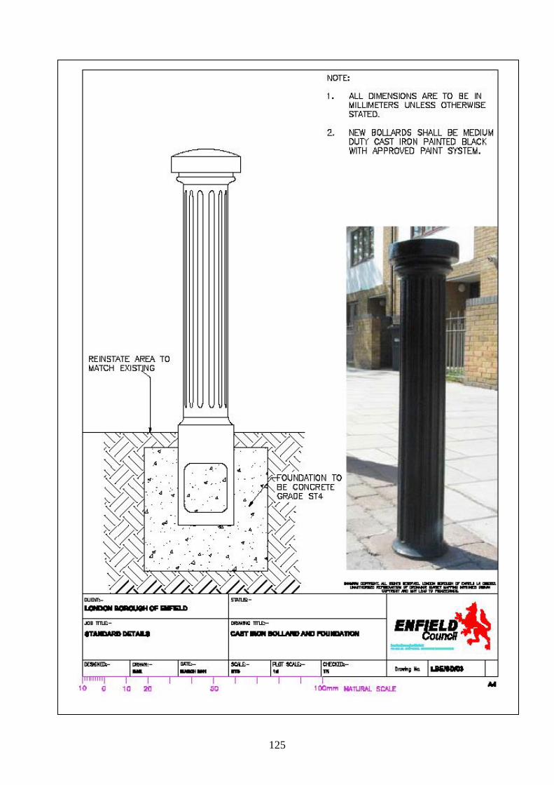
125
Intentionally Blank

126
Intentionally Blank

127

128
Intentionally Blank

129

130
Intentionally Blank

131

132
Intentionally Blank

133

134
Intentionally Blank

135

136
Intentionally Blank

137

138
Intentionally Blank

139