7 technical guidance: footways and carriagewaysplangate.no/areal-transport/london/streetscape/7 -...
TRANSCRIPT
7.1
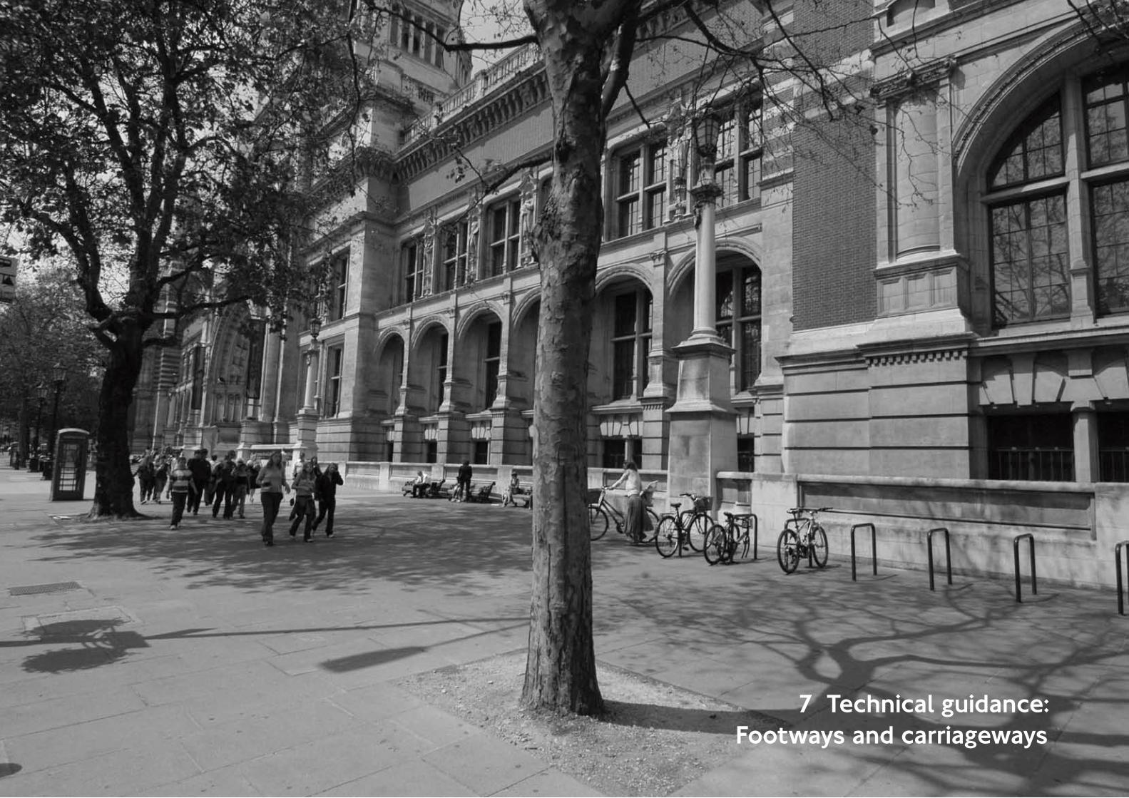
7 Technical guidance:Footways and carriageways

7.2
7 Technical guidance: footway surfaces
Introduction
It is the aim of TfL to provide high quality footways on the TLRN to promote walking as a sustainable method of transport.
The correct implementation and supervision of footway works by adequately skilled personnel is essential.
Good paving design forms an important element of any public highway. Good footway design with suitable materials can successfully enhance an area’s visual appearance.
New footway paving should be in keeping with the streetscape character area and take into account local distinctiveness in special areas. Good quality paving design and materials and an uncluttered street furniture layout aids legibility and enhances pedestrians’ perceptions of the built environment.
Footway construction must be able to cope with the loads, forces and foreseeable uses acting upon it. A properly constructed footway, with a foundation appropriate for its use, will be more durable over time and avoid failures leading to uneven paving and trip hazards for users.
Design criteria
The range of materials can be grouped into the following two categories:
Paving units
Paving units are defined as either precast concrete flags or natural stone flags.
Precast concrete flags are the most common paving type on the TLRN.
Concrete flags emulate but cannot match the weathered natural look of natural stone paving and are not as durable over time.
900mm x 600mm concrete flags are preferred for the TLRN, especially for extensive areas of new paving.
Concrete flags should be laid with a regular transverse bond across the footway at 90 degrees to the kerb. The minimum bond stagger should be 150mm.
Chamfered edge concrete flags should not be used. Small unit paving, such as 300 x 300mm units and 200 x 100mm units, should not be used.
For special areas, natural stone slabs may be appropriate. Natural Yorkstone and granite are more expensive in the short term but, when designed with an appropriate construction for their use, are generally more durable in the long term. They are usually supplied with a distinctive striation or finish and range of textures and are available from a variety of sources.
Asphalt paving
Asphalt is the most commonly used term for bituminous mixtures. Asphalt is usually applied on a Type 1 granular material sub-base, typically over expansive areas of footway on streets with grassed verges in suburban or suburban-rural fringe areas.
Mastic asphalt is used extensively in central London locations. It gives excellent durability and inherent strength as well as excellent waterproofing qualities. It is typically used in thicknesses of up to 25mm and laid on a concrete base. Mastic asphalt is expensive but can be an ideal material to use where structures such as basements, cellars or bridges exist under the footway.
These paving types should not be regarded as inferior. When designed and executed well, in conjunction with high quality kerbs and other elements, these materials can produce fine results.
Good practice
Footways must be wide enough to accommodate peak flows of pedestrians and allow for the presence of bus queues etc.
Surfaces should be smooth and non-slip and the gradient should allow for the drainage of surface water and be comfortable to walk upon.
Where vehicles are known to illegally mount footways to park or load, high kerbs should be used to prevent this behaviour. Design teams should take into account the difficulties that this may cause less mobile pedestrians and make suitable provision of dropped kerbs to assist pedestrians cross the carriageway where necessary.
Design teams should take into account barriers on the footway, ramps and steps, basements, cellars, street furniture and other potential obstructions.
Footway surfaces must provide a firm, even, slip resistant surface in both wet and dry conditions and avoid surface reflection of materials, which may affect pedestrians with visual impairments.
Design teams should consider the layout of paving to anticipate and minimise the amount of cuts that will be required.
Technical guidance
Core drilled flag

7.3
Particular care is required when dealing with changes in level. Design teams may need to show fold lines in surfaces on drawings. Generally the number of cut lines on footway surfaces is to be kept to a minimum and a single straight cut line used as opposed to several cuts. Cuts less than 150mm should be avoided wherever possible and slabs of constant width and various lengths used.
Mortar infills must be avoided at the backs of kerbs, at building faces and around utility covers, to achieve a high quality footway.
Mortar infills should also be kept to an absolute minimum around posts. The use of special paving (core drilled flags) is recommended.
Close butt joints should be provided wherever possible, for paving units to provide a high quality continuous surface, without a visible network of mortar joints.
The form of the bond must be considered where footways constructed with paving units turn corners, normally at junctions.
Careful cutting of paving units will be required to achieve a neat joint at the kerb edge and back of footway.
Square edged footway materials should be used wherever possible to ensure visual continuity.
Design teams may require a sample panel to be constructed for all footway paving materials to establish specified standards of workmanship for the scheme. The sample panel then becomes a benchmark which demonstrates the quality required. A typical trial area would cover about 30 square metres of footway and should include a kerb edge, a building line, several inspection covers, a radius and at least one dropped kerb.
Maintenance covers, gratings and tactile paving are an essential component of footways and as such have to be considered at the initial design stage. TfL advocates the use of inset covers help hide covers but these are expensive and utility companies will not maintain them.
When designing a section of footway that has private forecourts, cellars or basement lights particular care should be taken to ensure that the paving material chosen can join with these private areas without giving a patchwork effect.
In some instances it may be advantageous to gain the consent of the owner to re-aligning or renewing small areas of private forecourt to improve the overall design of the footway. In such cases it is usual to define it by fixing metal studs into the surface along the line of the property boundary, if the forecourt area is to remain private.
With reference to the use of new products on the TLRN, TfL has an internal procedure. Approval from the Streetscape Review Group should be obtained before the product is used.
References
Commission for Architecture and the Built Environment (CABE):
Paving the way. How we achieve clean, safe •and attractive streets, 2002
English Heritage:
Streets for All, 2005 •
Transport for London:
Making London a Walkable City. •The Walking Plan for London, 2004
Streetscape Guidance:
Palette of materials, Footways •
Streetscape Guidance details:
TfL/SG01, SG04, SG05, SG06, SG07, SG08, •SG09, SG10, SG11, SG12, SG13, SG14, SG15, SG16, SG17, SG18, SG21, SG24, SG25, SG26, SG28 and SG29
Footways and carriageways

7.4
Shared surfaces
Introduction
Shared surfaces are streets where traffic, pedestrians and cyclists mix, providing a dramatically changed public realm by removing the separation between the footway and carriageway. They have become a topical urban design issue, highlighted by examples such as Drachten in the Netherlands. These schemes also remove most of the standard signs and street furniture, giving designers much more flexibility and opportunity to create new forms of public realm.
There are many benefits produced by shared surfaces but there are also concerns for certain groups which need to be addressed to ensure fully inclusive design. The key groups which may be disadvantaged are people who are blind or partially sighted, who require the traditional delineators, such as kerbs, to guide them safely along a street. A report by the Guide Dogs for the Blind Association concludes that the confidence and independence of blind and partially sighted people are undermined by shared surfaces, with parts of some towns having become no-go areas. There are other people, such as those with no or limited hearing, children and elderly people, for example, who may become confused without a conventional street layout to follow.
Design criteria
Guidance on shared surfaces is being developed by TfL. Until this is published, any proposals to use shared surfaces on the TLRN will need to be approved by the Streetscape Review Group.
Good practice
TfL has set up a research group, entitled the Shared Surface and BVI165 Guidance and Research Group to identify, discuss and develop good practice to shared surface schemes.
The Shared Surface and BVI165 Guidance and Research Group includes members of the Greater London Authority group who have a particular interest in shared surface schemes and BVI165. The group will develop suitable actions and, where appropriate, shape good working practice.
References
University College London Pedestrian Accessibility and Movement Environment Laboratory (PAMELA):
Testing proposed delineators to demarcate •pedestrian paths in a shared space environment – Report of design trials conducted at University College London Pedestrian Accessibility and Movement Environment Laboratory (PAMELA), 2007
Guide Dogs for the Blind Association:
Shared Surface Street Design Research Project, •The Issues: Report of Focus Groups, 2006
Technical guidance

7.5
Tactile paving
Introduction
With increasing focus on the role of public space, social interaction by all members of the public has become an important issue. The special information needs of those members of society who are blind or partially sighted must be given particular consideration.
Tactile paving is available in a number of different textured and coloured surfaces depending on its intended application.
The most common use on the TLRN is the blister paving used to indicate to pedestrians with visual impairments that they are passing from a footway to a carriageway.
Blister surface should be installed at both controlled and uncontrolled crossing points where the footway has been dropped flush with the carriageway or the carriageway has been raised to the level of the footway.
Corduroy hazard warning surface should be used for any situation where visually impaired people need to be warned of a specific hazard (top and bottom of steps, foot of a ramp, when a footway or footpath joins a shared area, etc). This surface should not be used to warn of obstacles, such as cycle stands.
Lozenge warning surface should be used at the edge of an on-street light rapid transit platform.
Ladder and tramline warning surfaces should be used on segregated shared footway and cycle tracks to indicate to visually impaired pedestrians on which side they should walk. The Ladder pattern, with raised bars across the direction of travel, is used on the footway side; the Tramline pattern, with raised bars in the same direction as travel, is used on the cycle track. The DfT’s publication Inclusive Mobility and DETR’s Guidance on the use of tactile paving surfaces are important reference documents.
Design criteria
Where a crossing point is in the direct line of travel (eg, at a junction), the tactile surface should extend for the full width of the dropped kerb and for a depth of at least 1200mm.
Where a crossing point is not in the direct line of travel, a depth of at least 800mm should be provided.
At controlled crossings only, a stem of blister paving, 1200mm wide, should extend from the main area of tactile paving to the back of the footway to indicate to visually impaired pedestrians the existence of the crossing facility.
The colour of the tactile paving needs to contrast with surrounding paving to assist partially sighted people to distinguish the presence of the crossing point. Red tactile paving must be used at all controlled crossings and charcoal grey at uncontrolled crossings on the TLRN.
The requirement for red tactile paving may be relaxed in conservation areas, subject to expert advice. The decision should be documented.
Footways and carriageways
Tactile paving is available for the following applications:
Pedestrian crossings: •Parallel rows of flat-topped blisters that are 5mm high, 25mm in diameter and have a pitch of 64-67mm
Hazard warning surface: •Corduroy consisting in rounded bars 6mm high, 20mm wide and spaced 50mm apart
Segregated shared cycle track and footway •surface ladder and tramline pattern of flat-topped bars 5mm high, 30mm wide, and 70mm apart
On street platform edge: •Rows of lozenge shape 6mm high with rounded edges 150-83mm in plan
The following are to be used only in exceptional circumstances on the TLRN and subject to expert advice:
Guidance path surface: •Series of flat-topped bars (pedestrian travel direction) – 5.5mm high – 35mm wide and 45mm apart
Information surface: •No raised profile but detectable underfoot (softer) – matt finish and slip resistant

7.6
Good practice
The most important streetscape aspect of the use of tactile paving (other than compliance with the technical guidance on its shape and use) is the neatness of finish and care in its laying.
The presence of inspection covers and the changes in gradient associated with dropped crossings can make this difficult to achieve. The use of inset covers and the careful design of fold and cut lines in the footway surfacing material will be frequently required and the application of streetscape guidance details will need to be adapted at many locations.
Borders should not be provided around areas of tactile paving.
The careful design of the gradient of dropped kerbs and the use of quadrant kerb returns can simplify the design and produce a neat finish. They can, however, only be used when the design of any dropped kerbs and the vertical alignment (and height of kerb face) of the footway are well integrated so as to avoid trips.
References
Department for Transport:
Inclusive Mobility – A Guide to Best Practice •on Access to Pedestrian and Transport Infrastructure, 2002
Department of Environment, Transport and the Regions:
Guidance on the use of Tactile Paving •Surfaces, 1998
Institute of Highways and Transportation:
Guidelines for Reducing Mobility Handicaps – •Towards a Barrier-Free Environment, 1991
Streetscape Guidance:
Palette of materials: Tactile paving •
Streetscape Guidance details:
TfL/SG01, SG02, SG03, SG04, SG05, SG06, •SG07, SG08, SG09, SG10, SG11, SG12, SG17, SG18, SG22, SG25, SG26, SG27 and SG28
Technical guidance

7.7
Inspection covers
Introduction
Inspection covers, chambers and stop taps etc. are located in the carriageway. Collectively, they are often referred to as ironwork. Utility companies own the majority of ironwork that appears on the public highway.
A small proportion is owned by the highway authority and these relate to traffic signalling, drainage and CCTV surveillance equipment.
The utility company mainly predetermines the size and location of their ironwork to suit their own purposes. A highway authority can arrange to have a utility relocate its underground services, the costs of which may be high.
TfL supports the use of deep frames for utility access to achieve greater consistency of footway surface materials.
Good practice
The use of inset covers helps to hide the presence of inspection covers. The cost of these covers and their future maintenance will need to be borne by the highway authority. Inset covers will therefore only be justified to allow for tactile paving or in areas of natural stone paving where there is a particular case for consistency.
Attention given to the detailing around covers can have a considerable effect on the safety and appearance of the footway and needs to be carefully described on construction drawings and details.
The designer should ensure that the footway surface abuts the edge of the cover frame to avoid the need for unsightly cement infill. Where the structure of the frame is such that this cannot be achieved with rigid surfacing materials, the below ground masonry should be lowered and replaced with a deep frame to give increased depth. This allows close laying of the footway material, and the retention of the shallow infill cover.
There is usually a small element of flexibility to alter the orientation of ironwork within footways. Design teams should therefore seek to align the orientation of the edges of a cover with that of the bond employed on rigid footway surfaces.
Utilities have a right of access to their plant. Care is therefore needed to ensure that access to chambers is not impeded by the location of street furniture.
In high security areas, inspection covers may need to be marked. Advice should be sought from TfL’s Transport Community Safety Managers within the Community Safety, Enforcement and Policing directorate.
Special care is needed in the detailing of rigid footway surfaces that contain inspection covers where changes in the level occur, particularly where dropped kerbs are required. Ironwork cannot be made to fall in two directions (unlike flexible surfaces) and therefore careful consideration must be given to where rigid surfaces are folded.
This may require changes in level to be made more gradually than normal or a new cut line introduced into the surface (See Footway Surfaces section for good practice in relation to cut lines). When introducing new inspection covers onto the footway (eg, for traffic signal duct work) the design team must ensure that an appropriate cover is used and it is situated within the footway in an inconspicuous manner. This can be achieved by detailing the cover to be positioned to fall in a natural break in the bond of paving.
Responsibility
Installation and maintenance of inspection covers, etc, is the responsibility of the service owner. However, if a highway authority replaces the cover with an inset cover, the highway authority will assume the maintenance responsibility for the cover from that day forward.
References
Legislation:
New Roads and Streetworks Act 1991 •
British Standards:
BS 7903: Guide to selection and use of gully •tops and manhole covers for installation within the highway
BS EN 124: Gully tops and manhole tops for •vehicular and pedestrian areas
Streetscape Guidance details:
TfL/SG12, SG21 and SG22 •
Footways and carriageways
7.8
Kerbs and drainage
Introduction
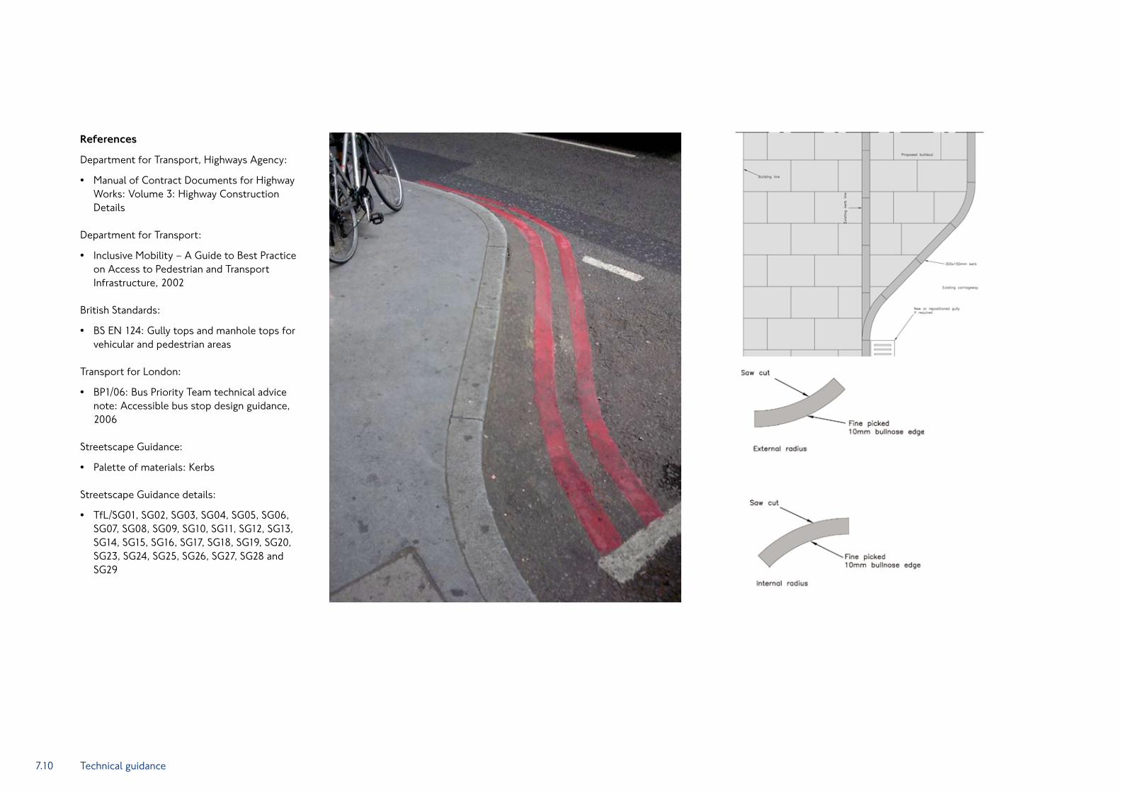
Kerbs are a significant visual element in the streetscape. Traditional granite kerbs, which are TfL’s ‘standard’, generally have a longer lifespan than other streetscape materials and therefore justify careful attention at design stage.
A kerb face (or upstand) of between 125mm and 140mm normally delineates the boundary of a carriageway. This provides a visible boundary for vehicular traffic and pedestrians and also channels surface water run off.
A smooth channel is provided adjacent to the kerb in the carriageway to assist cleansing. The channel is formed using either the same material as the carriageway surface, or occasionally from the same material as the kerb.
Effective surface water removal is essential for road safety and the comfort of all road users.
Drainage of the carriageway is usually achieved by the installation of gullies along the channel. Footway gullies are sometimes provided when a cross-fall across the footway into the channel cannot be achieved. To avoid ponding, the vertical alignment of the footway and carriageway surfaces must be designed so that surface water flows to the gullies.
Kerbs
Kerbs should typically have an upstand of 125mm. Higher kerb upstands can be used but careful consideration must be given to how people with mobility impairments gain access to the carriageway. Kerb upstands at bus stops should preferably be 140mm.
Gullies should be avoided along the length of dropped kerbs provided at pedestrian crossings (see also – at grade pedestrian crossings). Ideally, a gully should be installed immediately upstream of a pedestrian crossing to intercept runoff prior to the crossing.
Dropped kerbs should provide a gentle slope to minimise uneven footway surfaces. Internal and external radiussed kerbs should be used for all changes in kerb direction up to a radius of 12m to achieve smooth lines.
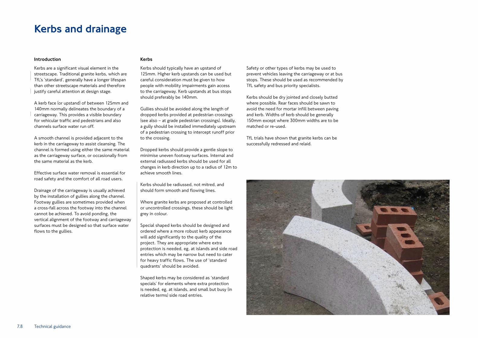
Kerbs should be radiussed, not mitred, and should form smooth and flowing lines.
Where granite kerbs are proposed at controlled or uncontrolled crossings, these should be light grey in colour.
Special shaped kerbs should be designed and ordered where a more robust kerb appearance will add significantly to the quality of the project. They are appropriate where extra protection is needed, eg, at islands and side road entries which may be narrow but need to cater for heavy traffic flows. The use of ‘standard quadrants’ should be avoided.
Shaped kerbs may be considered as ‘standard specials’ for elements where extra protection is needed, eg, at islands, and small but busy (in relative terms) side road entries.
Technical guidance
Safety or other types of kerbs may be used to prevent vehicles leaving the carriageway or at bus stops. These should be used as recommended by TfL safety and bus priority specialists.
Kerbs should be dry jointed and closely butted where possible. Rear faces should be sawn to avoid the need for mortar infill between paving and kerb. Widths of kerb should be generally 150mm except where 300mm widths are to be matched or re-used.
TfL trials have shown that granite kerbs can be successfully redressed and relaid.

7.9
Drainage
A conventional highway is constructed to have a camber or cross-fall on the carriageway and a cross-fall across the footway to the channel. Precast concrete trapped gully pots, installed along the channel, are connected to 150mm diameter pipe connections that discharge either directly to the nearest appropriate sewer or via a highway drainage pipe system. Gully pots should be positioned to drain a highway catchment area of approximately 200m.
Where the highway has a steep longitudinal fall, a storm gully cover and frame may be used in preference to a standard cover in order to reduce the tendency of the run-off to overshoot the gully. These covers are ‘handed’ and must be installed correctly in relation to the direction of flow of the run off.
Where there is little longitudinal fall, false summits should be introduced along the channel to encourage water to flow into the gullies.
On some highway structures, it is not always possible to use conventional gully pots due to insufficient construction depth. Alternative drainage systems should be designed into the structure in these circumstances. One alternative is to use combined kerb drainage blocks where water flows at minimum depth, within a perforated kerb unit. There is an expectation that these are easily blocked and require a higher level of maintenance but they have proved very effective on the A13.
Special attention should be given to providing adequate drainage where there are traffic calming features such as side road entry treatments and where the footway is being extended into the carriageway. These types of feature often change the vertical alignment of the carriageway and trap water, creating ponding.
Footways should drain into the channel, where run off finds its way into the carriageway drainage system. Where this cannot be achieved, such as in large areas of footway or where a back fall on the footway cannot be avoided, it may be necessary to provide some form of drainage within the footway. This may take one of three forms:
Conventional footway gullies or smaller •‘yard gullies’.
Shallow open channels which can either •connect to a footway gully or extend along the footway and turn run off water into the carriageway channel using changes of level afforded by the long fall of the highway.
A ‘U’ shaped channel covered with a •perforated metal grid.
Good practice
The use of footway drainage systems should be avoided wherever possible.
The gratings on footway and yard gullies provide only small perforations that block easily. Similar problems occur with ‘U’ shaped channels with the metal covers blocking. These systems also present cleansing problems and may be a trap for heels.
If the footway cannot be drained into the channel by means of a simple crossfall across the footway, design teams should design the footway surface to form an open channel. Rain water collecting in this channel should then be directed into the carriageway by using the highway longfall and turning the formed channel into the carriageway edge where the footway crossfall allows.
If an open channel is used on the footway, the channel may be created by forming the footway surface into a straight shallow ‘V’.
Carriageway drainage should be designed so that both the footway and carriageway will continue to drain satisfactorily if one or more gullies become blocked with litter. This is particularly important in areas adjacent to pedestrian crossings.
Footways and carriageways
7.10
References
Department for Transport, Highways Agency:
Manual of Contract Documents for Highway •Works: Volume 3: Highway Construction Details
Department for Transport:
Inclusive Mobility – A Guide to Best Practice •on Access to Pedestrian and Transport Infrastructure, 2002
British Standards:
BS EN 124: Gully tops and manhole tops for •vehicular and pedestrian areas
Transport for London:
BP1/06: Bus Priority Team technical advice •note: Accessible bus stop design guidance, 2006
Streetscape Guidance:
Palette of materials: Kerbs •
Streetscape Guidance details:
TfL/SG01, SG02, SG03, SG04, SG05, SG06, •SG07, SG08, SG09, SG10, SG11, SG12, SG13, SG14, SG15, SG16, SG17, SG18, SG19, SG20, SG23, SG24, SG25, SG26, SG27, SG28 and SG29
Technical guidance
7.11
Introduction
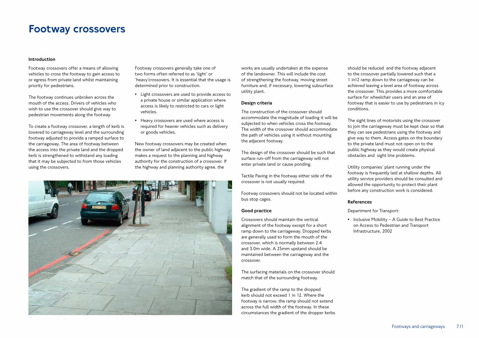
Footway crossovers offer a means of allowing vehicles to cross the footway to gain access to or egress from private land whilst maintaining priority for pedestrians.
The footway continues unbroken across the mouth of the access. Drivers of vehicles who wish to use the crossover should give way to pedestrian movements along the footway.
To create a footway crossover, a length of kerb is lowered to carriageway level and the surrounding footway adjusted to provide a ramped surface to the carriageway. The area of footway between the access into the private land and the dropped kerb is strengthened to withstand any loading that it may be subjected to from those vehicles using the crossovers.
Footway crossovers generally take one of two forms often referred to as ‘light’ or ‘heavy’crossovers. It is essential that the usage is determined prior to construction.
Light crossovers are used to provide access to •a private house or similar application where access is likely to restricted to cars or light vehicles.
Heavy crossovers are used where access is •required for heavier vehicles such as delivery or goods vehicles.
New footway crossovers may be created when the owner of land adjacent to the public highway makes a request to the planning and highway authority for the construction of a crossover. If the highway and planning authority agree, the
works are usually undertaken at the expense of the landowner. This will include the cost of strengthening the footway, moving street furniture and, if necessary, lowering subsurface utility plant.
Design criteria
The construction of the crossover should accommodate the magnitude of loading it will be subjected to when vehicles cross the footway. The width of the crossover should accommodate the path of vehicles using it without mounting the adjacent footway.
The design of the crossover should be such that surface run-off from the carriageway will not enter private land or cause ponding.
Tactile Paving in the footway either side of the crossover is not usually required.
Footway crossovers should not be located within bus stop cages.
Good practice
Crossovers should maintain the vertical alignment of the footway except for a short ramp down to the carriageway. Dropped kerbs are generally used to form the mouth of the crossover, which is normally between 2.4 and 3.0m wide. A 25mm upstand should be maintained between the carriageway and the crossover.
The surfacing materials on the crossover should match that of the surrounding footway.
The gradient of the ramp to the dropped kerb should not exceed 1 in 12. Where the footway is narrow, the ramp should not extend across the full width of the footway. In these circumstances the gradient of the dropper kerbs
should be reduced and the footway adjacent to the crossover partially lowered such that a 1 in12 ramp down to the carriageway can be achieved leaving a level area of footway across the crossover. This provides a more comfortable surface for wheelchair users and an area of footway that is easier to use by pedestrians in icy conditions.
The sight lines of motorists using the crossover to join the carriageway must be kept clear so that they can see pedestrians using the footway and give way to them. Access gates on the boundary to the private land must not open on to the public highway as they would create physical obstacles and sight line problems.
Utility companies’ plant running under the footway is frequently laid at shallow depths. All utility service providers should be consulted and allowed the opportunity to protect their plant before any construction work is considered.
References
Department for Transport:
Inclusive Mobility – A Guide to Best Practice •on Access to Pedestrian and Transport Infrastructure, 2002
Footway crossovers
Footways and carriageways
7.12
Side road entry treatments
Introduction
An entry treatment may be described as a traffic calming device which is normally placed across a minor road junction with a major road, either at the entrance to the junction or within a short distance of it. Entry treatments are generally used to denote the change in the character between a main traffic route and a road of a lower order, such as a residential street or access road.
Entry treatment seeks to achieve a combination of objectives, in particular, providing for easier pedestrian movement by raising carriageway level up to footway level, slowing vehicle speeds by reducing corner radii and deterring parking close to junctions by narrowing the carriageway.
Entry treatments aim to create a strong visual threshold for traffic leaving or entering the minor road, and to indicate to motorists the need to change their driving behaviour to accord with the different traffic conditions they are about to encounter.
Their use has been shown to reduce the numbers of accidents to vulnerable road users.
Design criteria
Raised entry treatments should be considered as an uncontrolled crossing and have tactile paving designed accordingly. The width of the raised crossing area should be at least 2.4m and the raised crossing area should be flush with the footway. If items of street furniture are to be incorporated into the entry treatment, they should be provided in accordance with the general design principles for street furniture. In many cases, additional drainage arrangements will be required.
Vertical deflection
It is common practice to use a flat-topped road hump to create the raised area. Such raised areas will invariably cause the vertical deflection to exceed the 75mm height that is more normal for road humps. Therefore particular consideration must be given to ensuring that the ramp gradients and length of raised area are sufficient to avoid grounding of vehicles. Vertical deflections must not prevent reasonable access by emergency services. Bus access and HGV delivery also need to be considered.
Materials
Asphalt should be used. Concrete or granite kerbs, matching the footway kerbs, may be used to make a clearly defined and neat junction between walking surface and ramps.
Carriageway narrowing
The extent to which the carriageway might be narrowed will depend on local circumstances including traffic flows, vehicle sizes, vehicle types (eg, emergency vehicles) and turning movements.
Where the side road forms a one-way street, carriageway widths should normally be sufficient only for single vehicle access or egress, typically in the range of 3.5-4.0m. If the side road has two-way flow a minimum width of 5.5m should be provided.
Care should be taken to reform kerblines and to relocate drainage gullies when the carriageways are narrowed.
Radius kerb alignments should be used, with the angle of kerb return no greater than 45 degrees.
Location
Entry treatments are normally only used in urban areas. Depending on the features they incorporate, they may be used alone or to indicate the start of a series of traffic calming measures.
They can be an effective means of identifying the beginning of 20mph zones.
Entry treatments should be located so that they do not interfere with vehicle access to frontage properties. They should not be used adjacent to roads where vehicle speeds are high, as vehicles turning onto the ramp and raised table will be moving at low speeds.
Good practice
Appropriate ‘give-way’ markings and signs must still be provided where traffic may emerge from a side road. These signs and markings must comply with Traffic Signs Regulations and General Directions. In order to control the speed of vehicles turning into side roads the kerb radii should be small (approximately 3m).
The side road entry area should be adequately illuminated in accordance with BS5489 and BS EN13201.
References
Legislation:
Highways Act 1980 •
Traffic Calming Act 1992 •
Statutory Instruments:
Traffic Signs Regulations and •General Directions 2002
Highways (Road Hump) Regulations 1999 •
Department for Transport:
Traffic Advisory Leaflet 02/94: •Entry Treatments
Traffic Advisory Leaflet 13/93: •Gateways
Traffic Advisory Leaflet 3/93: •Traffic Calming Special Authorisations
Traffic Advisory Leaflet 7/96: •Highways (Road Hump)
Department for Environment Transport and the Regions:
Guidance on the Use of Tactile Paving •Surfaces, 1998
British Standards:
BS 5489-1: Code of practice for the design of •road lighting
BS EN 13201: Road lighting •
Streetscape Guidance:
Palette of materials: •Side road entry treatments
Streetscape Guidance details:
TfL/SG06, SG07, SG08, SG09, SG10, SG11, •SG12 and SG28
Technical guidance

7.13Footways and carriageways
Road markings
Introduction
Road markings are the lines, patterns, words or other devices, applied or attached to the carriageway for controlling, warning, guiding and informing the road user.
They can also act as a psychological barrier, signify the delineation of traffic lanes and provide lateral clearance from traffic hazards for the safe movement of traffic.
Road markings are vital to ensure smooth and orderly flow of traffic and for promoting road safety.
Reflective road studs supplement linear road markings and can be particularly effective at night in enhancing the objectives of warning and guiding road users.
Design criteria
Road markings are normally made from a hot applied thermoplastic screed with glass beads applied to provide a retro-reflective surface. Durable paints are also used but typically do not provide the same retro-reflective quality that can be achieved with thermoplastic.
Skid resistance is an important consideration, particularly when markings are applied to larger areas of the carriageway. Metal road studs should be avoided as they can cause particular problems for two wheeled vehicles.
All markings and colours should be in accordance with the regulations, British Standards and TfL’s specification.
The Traffic Signs Manual Chapter 5 allows minimum widths of lines. TfL considers 50mm to be appropriate for design speeds of 30mph which should be used where the design team considers that it is appropriate to do so, taking specialist
advice as necessary. 100mm lines are to be used for roads of higher design speeds.
Design teams should, however, take account of enforcement requirements and the need for consistency.
Good practice
The extent of road marking is to be kept to the minimum necessary to:
Ensure safety •
Achieve compliance with traffic regulations •
Provide sufficient information for lane •discipline
Sprayed paint may be used instead of thermoplastic but is much less hard wearing and will require more frequent maintenance.
Thermoplastics should be avoided on concrete blocks and natural stone and will require more frequent replacement.
Specialist hard wearing pre-formed thermoplastic paints that adhere to concrete and stone are available but expert advice should be sought before specifying these products.
During routine maintenance when road markings are often re-marked it is important to ensure the new surface is accurately applied over the old material so that the edges of the markings remain crisp and of the desired width.
Poorly maintained road markings are much more unsightly than well-maintained markings and detract from the streetscape. The excessive build up of thermoplastic, which can lead to ponding of surface water, should also be avoided.
When road markings are removed, it is important that all the thermoplastic or road paint is removed. Ghost images of old markings are unsightly, detract from the streetscape and can have an impact upon road safety.
The bulk of road marking material should be removed by mechanical means, and there are environmentally-friendly sand blasting techniques now available that can remove road markings cleanly without damaging the road surface.
Hard wearing highly reflective preformed thermoplastic markings are available but expert advice should be sought before specifying these products. The use of preformed markings is preferred when forming more complex shapes and symbols, such as for cycle routes and speed limit roundels.
Yellow boxed areas can look unsightly and consideration should be given to using advisory ‘KEEP CLEAR’ white text markings where legal enforcement is not necessary.
References
Statutory Instruments:
Traffic Signs, Regulations and General •Directions 2002: Section 4 and Schedule 6 (Road markings)
Department for Transport:
Traffic Signs Manual, Chapter 5: Road Markings •
7.14
Bus lanes
Introduction
A bus lane is a traffic lane on the public highway which is reserved for buses and other specified modes of transport. Some bus lanes operate at designated times.
In some situations, heavy goods vehicles are also permitted to use bus lanes. TfL is also trialling the use of bus lanes by motorcyclists.
Taxis and cyclists are usually permitted to use bus lanes. If it is required to specifically exclude cyclists, special authorisation from DfT isrequired and alternative provision must be made for cyclists.
Bus lanes
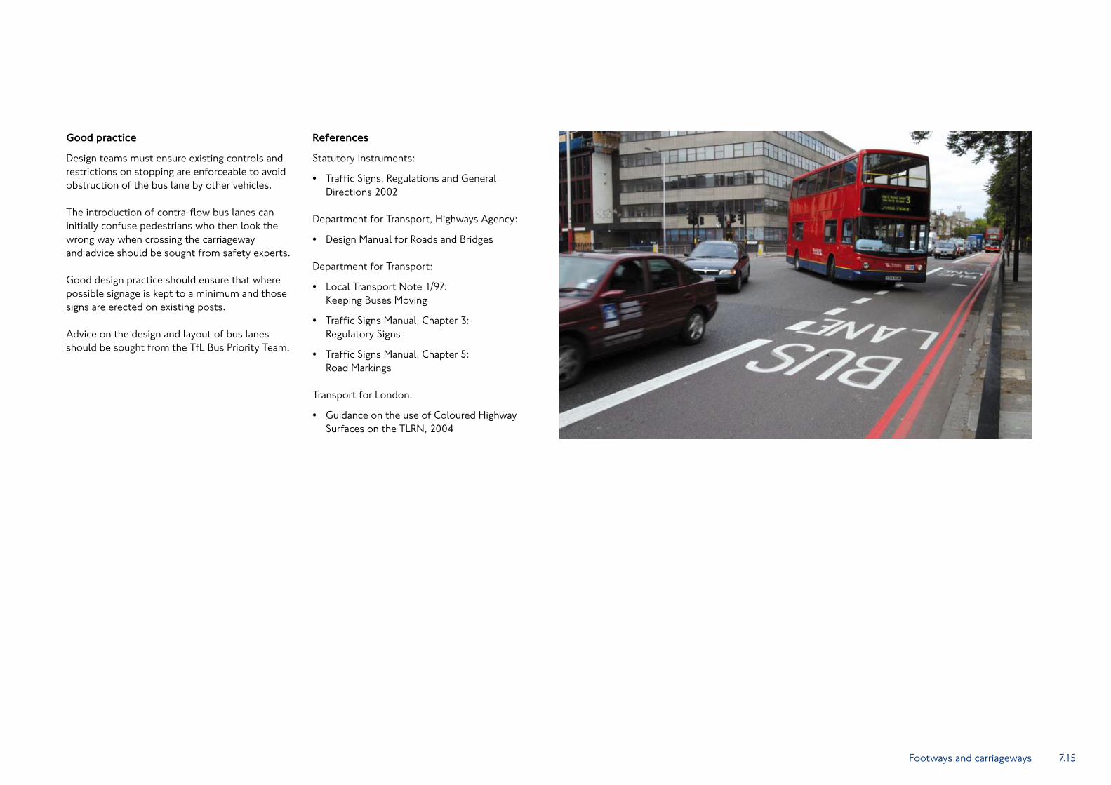
Bus lanes are usually located at the kerbside, in order to serve bus stops. Their primary purpose is to give buses priority at the locations and times most needed whilst minimising disruption to general traffic.
TfL policy is to use venetian red coloured surfacing to bus lanes since this has been found to aid compliance with bus lane traffic regulations by making the bus lane more conspicuous. The preferred treatment for bus lanes is a pigmented thin surface course system, unless site conditions or location demand an alternative approach.
Bus lanes are only enforceable when the road markings and signing comply with the Traffic Signs Regulations and General Directions (TSRGD). Design teams will need to consider how the signing can be introduced without unnecessarily increasing street clutter by, for example, introducing more posts onto the footway.
The above may involve erecting the signs on lamp columns (see also the Traffic Signs and Street Lighting sections). Where this is being considered, it should be noted that the signs used at the start of the bus lane (and as repeaters following side road junctions) are too large to be erected on standard strength lamp columns (see also the Traffic Signs and Street Lighting sections). In these circumstances, it may be necessary to replace the lamp column with a higher strength column.
The selection for the location of the start and end points of a bus lane is critical to its success and safety. Lanes should start upstream of the predicted traffic conflict (queues) and be located to ensure that excluded traffic has a safe distance to merge into alternative lanes. When determining the precise position of these points, the coordination of the regulatory signing with other street furniture must be considered (see above).
Minor amendment of the bus lane design, moving the start and finish points by a few metres, may enable the use of existing street furniture to locate regulatory signing, thus minimising clutter.
The use of cycles in bus lanes
There should be a general presumption that cycles will be allowed to use bus lanes. Only where a contra-flow, or a with-flow offside bus lane is being planned, and there is a concern for the safety of cyclists, should their exclusion be considered. Even here though, a comparison should be made with the relative risks that they might face on the alternative route.
Design criteria
In determining the practicability and feasibility of implementing a bus lane within the existing built environment and infrastructure, consideration should be given to:
The volume of potential bus users •
The carriageway width •
The overall capacity of the carriageway •
The proximity of street trees to the •carriageway
If the above considerations satisfy and warrant the need for design, the following points must be implemented where possible:
Signage – existing and proposed regulatory •signage should be consistent along the route, clear, unobstructed and in accordance with TSRGD
Road markings – need to be modified as •appropriate in accordance with TSRGD
Pigmentation – where coloured surfaces •are appropriate, pigmentation should be Venetian red (BS381C – Colour 1434)
Technical guidance
7.15
Good practice
Design teams must ensure existing controls and restrictions on stopping are enforceable to avoid obstruction of the bus lane by other vehicles.
The introduction of contra-flow bus lanes can initially confuse pedestrians who then look the wrong way when crossing the carriageway and advice should be sought from safety experts.
Good design practice should ensure that where possible signage is kept to a minimum and those signs are erected on existing posts.
Advice on the design and layout of bus lanes should be sought from the TfL Bus Priority Team.
References
Statutory Instruments:
Traffic Signs, Regulations and General •Directions 2002
Department for Transport, Highways Agency:
Design Manual for Roads and Bridges •
Department for Transport:
Local Transport Note 1/97: •Keeping Buses Moving
Traffic Signs Manual, Chapter 3: •Regulatory Signs
Traffic Signs Manual, Chapter 5: •Road Markings
Transport for London:
Guidance on the use of Coloured Highway •Surfaces on the TLRN, 2004
Footways and carriageways

7.16
Cycle lanes and cycle tracks
Introduction
A variety of different types of cycle facility will need to be incorporated on the road network. These will include on-carriageway cycle lanes, and off-carriageway cycle tracks, adjacent and shared paths.
At junctions and crossing points special cycle crossings or Toucan (shared pedestrian and cycle crossings) may be required as part of the range of measures that are needed to cater for cyclists.
A summary of key points relating to the links (excluding junctions and crossings) is contained within the following section.
Cycle facilities should be installed with careful consideration of the needs of cyclists in context with other priorities. High quality cycling conditions encourage this environmentally-friendly mode of transport.
Wherever cycling takes place, the surface conditions must be suitable, this means that suitable maintenance procedures must be put in place.
Any designer of cycling facilities should refer to the London Cycle Design Standards (TfL 2005) which is available on the TfL website.
Cycle lanes (on-carriageway)
Cycle lanes are parts of the carriageway reserved for cyclists. They may be either mandatory or advisory. Mandatory cycle lanes are enforceable, excluding all other vehicles for all, or part, of the day.
Cycle lanes usually provide for travel in one direction only, and this will generally be the same direction as other vehicles. But contra-flow cycle lanes, against the flow of other vehicles, can be provided in certain circumstances.
Cycle lanes can also give the impression to drivers of other vehicles that this is where cyclists belong, resulting in danger for those cyclists who legitimately need to leave the lane. The visual impact of signs and road markings associated with cycle lanes should be considered.
Shared bus and cycle lanes are dealt with in the Bus lanes section.
A solid white line in reflective thermoplastic must be used to mark the boundary of a mandatory cycle lane. A broken line marks the boundary of an advisory cycle lane.
When designing a cycle lane, a width of 1.5m should normally be used. This ensures that cyclists can avoid riding over road gullies and along channel lines that may be uneven, wet or icy. If carriageway width allows, design teams should consider increasing the cycle lane width to 2.0m where cycle flows are high. Gully gratings must never be parallel to the cyclists’ direction of travel.
Cycle tracks (off-carriageway)
Cycle tracks are facilities dedicated for cyclists that are separated from the carriageway. Shared paths that can be used by pedestrians and cyclists can also be provided.
As a general principle, the presumption is that the footway along the TLRN should only be used by pedestrians.
In some circumstances, however, cyclists may be permitted to use the footway. This requires a change in the legal status of the footway to cycle track together with the appropriate signage and any necessary construction works. These circumstances include:
Where the footway is wide enough to •accommodate both pedestrian and cyclists with adequate segregation and without lowering the level of service provided to the pedestrian
Where a cycle route crosses the TLRN and •the crossing movement of cyclists cannot be safely accommodated in the carriageway
Where the width of the carriageway is •insufficient to safely accommodate general traffic and cyclists and the pedestrian flow along the footway is low
Where cycle tracks are provided the appropriate signing must be erected, but consideration must be given to minimising street clutter. The height of signing above the footway/cycle track must be checked to ensure adequate clearance for cyclists. Where cyclists pass under any signage a clearance height of 2.4m must be provided. For cycle routes that pass under obstacles less than 23m in length, a minimum headroom of 2.4m should be provided. Obstacles greater than 23m in length require a minimum headroom of 2.7m.
For equestrian routes, a minimum headroom of 3.4m should be provided for horses with riders and 2.8m for horses being led.
Design criteria
A prime factor in determining whether to provide mandatory or advisory cycle lanes is the need for other vehicles to gain access to the kerbside for loading and parking purposes. Where double red lines exist and adequate carriageway width is available, mandatory cycle lanes are preferred.
Consideration must also be given to introducing advanced stop lines (ASLs) at traffic signals to improve cycling conditions at junctions.
When providing cycle lanes or cycle tracks within the streetscape other factors that must be considered at the design stage include:
Route design – cycle lanes and tracks should •be convenient to use, coherent, direct, attractive, safe and comfortable with good running surfaces. This requires special attention to: road geometry that does not present a hazard; skid resistance; continuity; good signing (where necessary); ironwork and maintenance
Technical guidance

7.17
Plants – the choice of trees and shrubs in •planting areas must take into account future growth and future maintenance requirements. Cyclists may leave cycle lanes and tracks to avoid overhanging vegetation growth and travel into the path of pedestrians and vehicles.
Design teams should seek advice from TfL’s Route Managers – Arboriculture and Landscape, with regard to the maintenance regime. Plants with thorns should be avoided as pruning can result in cycle punctures.
Street lighting columns – most segregated •cycle tracks run close to the kerb edge where street lighting columns are usually placed throughout London. Design teams will need to seek advice on the positioning of street lighting columns at an early stage in the design process to ensure that adequate widths for both pedestrians and cyclists can be achieved, whilst maintaining lighting levels on the footway, cycle track and main carriageway, without columns causing a physical obstruction. In some circumstances, it may only be possible to achieve adequate width for pedestrians and cyclists by moving the lamp column
Signage and road markings – candatory cycle •lanes and cycle tracks are only enforceable when the appropriate road markings and signing comply with the TSRGD. Design teams will need to consider carefully how the signing can be introduced without increasing street clutter. This may involve erecting the signs on lamp columns. Where other signing already exists on suitably located columns, the additional signing may cause wind loading to exceed the tolerance of standard strength lamp columns
It may in these circumstances be necessary to replace the lamp column with one of higher strength, but with the same appearance or seek opportunities to relocate the existing signing to other existing posts or columns (see also the Traffic Signs and Street Lighting sections).
The consideration of how and where signs are to be erected for cyclists and cycle facilities must therefore be carefully considered at the design stage of both the introduction of cycle facilities and when changing street lighting.
Road signs and markings must be •placed correctly
Dropped kerbs – where cycle tracks or shared •paths are provided, flush kerbs must be incorporated at entry and exit points to assist cyclists on to and off the carriageway
Coloured surfacing may be applied to cycle •lanes to increase conspicuity of the facility for all road users. TfL policy is only to provide green surfacing to mandatory cycle lanes, to advisory cycle lanes across side road junctions, to advanced stop line areas and other areas of potential cycle conflict
However, the provision of highly conspicuous surfacing can detract from the aesthetics of the streetscape and may not be appropriate in special or conservation areas. Advice should be sought from TfL’s Cycling Centre of Excellence.
Where coloured surfaces are appropriate, pigmentation should be deep chrome green (BS381C – Colour 267).
Footways and carriageways
Good practice
The London Cycle Design Standards (LCDS) are the definitive guide to design for cycling in London.
The attractiveness of the route is important to existing cyclists and can also attract new users. Design teams should therefore consider the total experience of the cyclist on the journey. This means paying attention to the environmental quality of the route and engineering details.
Cycling facilities should enhance the area through which a route passes, not detract from it. Good quality urban design is therefore essential. Enforcement of stopping regulations, to avoid obstruction by other vehicles of specialfacilities such as cycle lanes and shared bus and cycle lanes, must be achieved if the benefits to cyclists are to be realised.
When designers use the cycle symbol to TSRGD diagram 1057 they should use preformed road markings. Hand-formed cycle symbols invariably have a poor appearance.
The slots in gully grates should be set so as not to align with bicycle wheels. All gully grates should be flush with the road surface.
The skid resistance of surface materials is very important to cyclists and design teams should ensure materials comply with appropriate standards.

7.18
References
Statutory Instruments:
Traffic Signs, Regulations and General •Directions 2002
Department for Transport, Highways Agency:
Design Manual for Roads and Bridges, Volume •5, Section 2, Part 4 TA 91/05: Provision for Non-motorised Users
Design Manual for Roads and Bridges: Volume •6 Section 3, Part 5 TA 90/05: The Geometric Design of Pedestrian Cycle and Equestrian Routes
Design Manual for Roads and Bridges, Volume •6, Section 3, Part 1 TD 36/93: Subways for Pedestrian and Pedal Cyclists Layout and Dimensions
Department for Transport:
Traffic Signs Manual, Chapter 5: Road Markings •
Local Transport Note 1/04 Policy Planning and •Design for Walking and Cycling
Local Transport Note 2/04 Adjacent and •Shared Use by Pedestrians and Cyclists
Transport for London:
London Cycling Design Standards, 2005 •
Guidance on the use of Coloured •Highway Surfaces on the TLRN, 2004
London Cycling Action Plan, 2004 •
Streetscape Guidance:
Palette of materials: •Cycle tracks, Cycle lanes, Shared surfaces
Streetscape Guidance details:
TfL/SG04, SG05, SG10 and SG11 •
Technical guidance
7.19Footways and carriageways
Subways
Introduction
Subways are most common on high speed roads on the TLRN. From a road safety perspective, subway crossings are considered safer although they can cause difficulties for people with mobility impairments. They may also give rise to concerns about pedestrian personal security or simply present an unpleasant environment. As a result, some pedestrians will endeavour to cross heavily trafficked carriageways in an effort to avoid using them.
Closure of subways
When reviewing the streetscape of the TLRN, opportunities for introducing safe new at-grade pedestrian crossings as alternatives to subways should be explored.
Good practice
New subway crossings should be located where there is high demand to provide a pedestrian crossing and where a safe at-grade facility cannot be provided because of the speed of vehicles or without causing excessive congestion and delay to public transport. In these circumstances, they should be located as close as possible to where pedestrian desire lines cross the carriageway. To help pedestrians find and use the subway, appropriate information signing may be required directing them to the crossing.
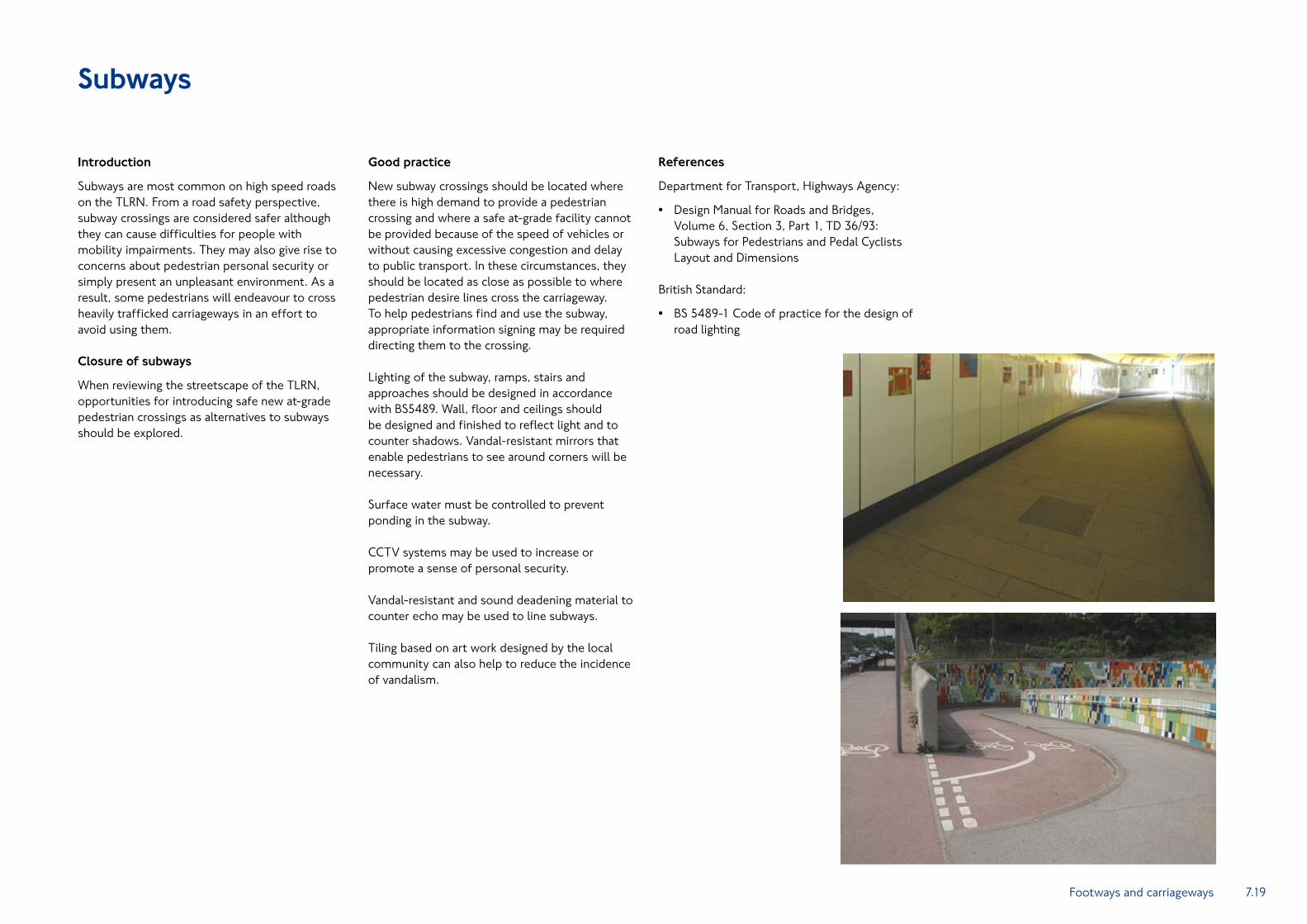
Lighting of the subway, ramps, stairs and approaches should be designed in accordance with BS5489. Wall, floor and ceilings should be designed and finished to reflect light and to counter shadows. Vandal-resistant mirrors that enable pedestrians to see around corners will be necessary.
Surface water must be controlled to prevent ponding in the subway.
CCTV systems may be used to increase or promote a sense of personal security.
Vandal-resistant and sound deadening material to counter echo may be used to line subways.
Tiling based on art work designed by the local community can also help to reduce the incidence of vandalism.
References
Department for Transport, Highways Agency:
Design Manual for Roads and Bridges, •Volume 6, Section 3, Part 1, TD 36/93: Subways for Pedestrians and Pedal Cyclists Layout and Dimensions
British Standard:
BS 5489-1 Code of practice for the design of •road lighting

7.20
Parking and loading bays
Introduction
The use of parking or loading bays marked within the carriageway should be used to provide for servicing where no other alternative for servicing exists.
Parking or loading bays defined by means of an appropriate Traffic Regulation Order can be designed to operate for all or part of the day. They can be similarly controlled to restrict the maximum duration of stay within a box.
It is important that designers understand the differences between parking activities and loading activities.
A loading activity is generally where a driver causes their vehicle to stop on a highway for the purposes of delivering and collecting goods between a nearby property and a vehicle.
A parking activity is when a driver decides to stop their vehicle on a highway for any other purpose (and typically the driver leaves the vehicle).Parking or loading bays in which vehicles are
permitted to stop for the entire period that adjacent single red line controls operate are marked with broken white lines.
Parking or loading bays in which vehicles are permitted to stop for a restricted part of the time that adjacent single red line controls operate are marked in broken red lines.
The nature of the activity, time of day and the duration for which an activity is permitted must be indicated on a sign erected adjacent to the box for the controls to be enforceable.
Parking bays can be specifically dedicated for use by a particular type of vehicle eg, buses, coaches or motorcycles.
Parking bays can be reserved for particular types of user eg, Blue Badge holders or doctors.
Design criteria
The allocation of kerb space to allow loading or, where appropriate, parking is important for the operation of business and commercial interests.
Stopping, parking and loading controls should be used to assist the free and safe flow of traffic, particularly buses. Parking or loading bays should be designed to ensure that their use (and turnover of use) is appropriate to the land use and streetscape.
Minimum widths for on-street bays for various vehicles and activity are:
1.8m for parking motorcycles, taxis and cars •
2.4m for vehicles to load and unload •
2.7m for bays reserved for Blue Badge holders •
Minimum lengths for on-street parking bays for various vehicles are:
6.6m for bays for Blue Badge holders •
No restrictions for other vehicles •
The nature of the land use adjacent to the carriageway will determine the type and duration of the parking and loading activity that may be required to take place in bays on the carriageway. The periods during the day when that activity may be permitted to take place is largely determined by the capacity of the highway and the potential of creating avoidable congestion.
Changes in usage may occur over time. Design and operation teams will need to react to changes.
Designers must consider how permitting a vehicle to stop on the carriageway will affect the sightlines and safety of people crossing, travelling along and stopping on the carriageway.
Designers must provide for accessibility to the footway especially when introducing loading or Blue Badge parking bays. The introduction of a dropped kerb within or next to the box must be considered, especially where the use of trolleys and other heavy and bulky goods is likely to occur.
Technical guidance

7.21
Location criteria
Bays that permit people to stop vehicles should only be introduced where there is no viable alternative location to stop off the highway.
Only in exceptional circumstances should the introduction of inset bays be considered. Such circumstances usually involve a wide footway, a clear demand for loading or servicing, and a particular need to keep traffic lanes unobstructed.
The convenience of motorists is not a suitable reason for a parking box within the footway. Where designers feel that installing bays should be considered on the footway, TfL must be consulted and agreement sought.
When designers consider that a need exists to provide bays, they should be located in side roads adjacent to the TLRN, wherever possible. Agreement must be obtained from the highway and traffic authority for the length of side road affected.
The following is given as guidance:
Loading bays – along or adjacent to streets •with commercial and/or industrial premises or at places where cash, mail or other valuables are delivered or collected
Parking bays – along streets with commercial, •industrial, residential premises
Disabled Bays – reserved for Blue Badge •holders must be considered close to local amenities. Local groups representing people with mobility impairments should be consulted when designing stopping controls and their suggestions for suitable locations for ‘disabled only’ bays sought
Parking should not normally be permitted within bus or mandatory cycle lanes during the hours in which the lanes operate. Loading may be permitted in certain circumstances, but must be carefully enforced to ensure that the facility is not compromised.
Good practice
When there is a need to place bays on the carriageway, designers must consider the signing required for enforcement.
The location of the box and its signing should take account of and co-ordinate with other street furniture to avoid clutter (see also the Traffic Signs section). The following must be considered:
Parking and loading facilities should be located •for the convenience and safety of all road users, not just motorists
Bays must be visible to motorists and •pedestrians through the use of appropriate markings
Parking bays should not be introduced in the •carriageway where there are suitable off-street opportunities for motorists to park
Parking and loading bays should be constructed using radiussed kerbs and their surfaces should be asphalt.
When designing the signing associated with bays, the smallest allowable text size ‘X’ height available should be used to keep the size of the sign to a minimum.
Designers should orientate the signs as required by the Traffic Signs Manual.
The colour of the backs of signs and any dedicated poles supporting them should be consistent with other street furniture, ie. black or grey in accordance with the palette.
References
Statutory Instruments:
Traffic Signs, Regulations and General •Directions 2002: Section 4 and Schedule 6 (Road Markings)
Department for Transport:
Delivering the Goods: •Guidance on Delivery Restrictions
Inclusive Mobility – A Guide to Best Practice •on Access to Pedestrian and Transport Infrastructure, 2002
Traffic Signs Manual, Chapter 5: Road Markings •
Transport for London:
Kerbside Loading Guidance •
Streetscape Guidance details:
TfL/SG13 •
Footways and carriageways

7.22
At-grade pedestrian crossings
Introduction
When seeking to create a high quality walking environment, it is essential that safe pedestrian crossings be provided where pedestrian desire lines cross the carriageway. Desire lines should be ‘true’, not perceived, and take account of safety.
The design team should consider the impact of the crossing point on the appearance of the streetscape, and ensure it is integrated into the overall design and co-ordinated with other features such as lighting, tree planting, building entrances and side roads.
Whilst crossing points can change pedestrian desire lines, they will not be successful if they radically change the direction of flow. The provision of pedestrian guard rail to control pedestrian movement in order to counter poor design is not acceptable to TfL.
Design criteria
Several different forms of pedestrian crossings exist and are found on the TLRN.
Uncontrolled crossings where pedestrians do •not have priority over vehicles and must make a decision when it is safe to cross. Examples include pedestrian refuge islands, side road junctions, and signal controlled junctions without pedestrian phases
Pedestrian refuge islands provide a safe place for pedestrians to stand within the carriageway whilst waiting for a sufficiently large enough gap in vehicular traffic flows to cross one or more traffic lanes.
Controlled crossings where pedestrians can •establish priority over vehicles. Examples include zebras, pelicans, puffins, toucans and signal-controlled junctions with pedestrian phases
Controlled pedestrian crossings should be located on pedestrian desire lines, where sight lines and/or speed of vehicular traffic will not endanger pedestrians crossing the carriageway and where they will not cause severe congestion and delay public transport.
At junctions controlled by traffic signals, pedestrian phases are frequently introduced to provide a safe means to cross the carriageway. Pedestrians are invited to cross by farside signal heads.
Zebra crossings are indicated by alternating •black and white bands within a controlled area marked by zigzag lines accompanied by flashing belisha beacons. Pedestrians only have right of way once on the zebra crossing markings. This type of crossing is therefore not suitable when vehicle speeds are high
Pelican traffic signal controlled crossings are •marked with studs within a controlled area marked by zigzag lines. Pedestrians activate the crossing by pushing a button and waiting for vehicular traffic to be stopped by a red signal. Farside signal heads are used to invite pedestrians to cross when it is safe to do so. These are appropriate where pedestrian flows are high and/or vehicles travelling at relatively high speeds
Puffin (‘pedestrian user friendly intelligent’) •crossings are similar to pelican crossings but have near side pedestrian signal heads, kerb side detection of pedestrians to cancel pedestrian demands which are no longer required, and infra red on-crossing detectors to extend the all red period. This type of crossing is planned to replace the pelican type
Zebra, pelican and puffin crossings must have a minimum crossing width (between two rows of studs) of 2.4m.
Toucan (‘two can cross’) signal controlled •crossings combine pedestrian and cycle movements across the carriageway. These crossings have both nearside and farside pedestrian and cycle heads
Toucan crossings should have a minimum crossing width of 4m. No regulations define a minimum crossing width at pedestrian refuge islands. It is essential that the refuge island is large enough to contain the number of pedestrians and cycles (where applicable) likely to use the crossing, and there should be sufficient carriageway remaining to prevent vehicles passing too close to the island or footway, which can intimidate pedestrians.
Dropped kerbs and appropriately coloured tactile paving must be used to assist pedestrians, refer to sections Tactile paving and kerbs and drainage.
Technical guidance

7.23
Good practice
Good practice principles associated with the introduction of street furniture, footway surfaces and tactile paving apply.
This can be achieved by locating traffic signalling equipment on other items of street furniture (street lighting columns), careful design of dropped kerbs and using inset covers to hide ironwork and the correct design of tactile paving.
Anti-skid surfacing should not be applied to the carriageway surface between the crossing studs as pedestrians with mobility impairment can experience difficulties in crossing. Coloured surfacing should not be used, unless green surfacing is required to assist in defining a cycle route at a toucan crossing.
Careful consideration must be given to the need to provide kerbside pedestrian guard railing. This should only be introduced where there is evidence that pedestrian safety could otherwise be compromised.
Carriageway drainage gullies should be located away from the pedestrian route across the crossing and outside any area enclosed by studs. Carriageway finished levels must enable surface water to drain away from the crossing point to prevent ponding at dropped kerbs.
Design teams must ensure that there is sufficient storage space on the footway adjacent to the crossing to permit waiting pedestrians to stand without obstructing the free movement of other pedestrians. This can usually be achieved by using a 5m crossing width on footways 2m to 3m wide.
When pedestrian crossings are introduced at locations where very large pedestrian flows exist (eg, outside public transport interchanges), it may be necessary to increase storage capacity by widening the footway into the carriageway and increasing the width of the crossing above 5m. Carriageway lane widths and signal timings need to be considered as part of this calculation.
When designing controlled pedestrian crossings, straight across arrangements are more sympathetic to creating uncluttered streetscapes than staggered crossings (with two independent crossings over each half of the carriageway) and should be the desired solution. Staggered crossings require a pedestrian holding place in the centre of the carriageway, which is either defined by kerbs or pedestrian guard railing and can also mean additional street furniture such as signal poles.
Where crossing distances are greater than 15m, the use of staggered crossings cannot be avoided without creating extended vehicle stopping time to allow pedestrians to walk across the road in one movement. To achieve straight-across crossings, design teams should consider analysis of signal timings over a section of highway to create even flows of traffic, preventing congestion at any one crossing.
When staggered crossings are unavoidable, design must be as simple and uncluttered as possible with the layout of stagger such that pedestrians on the island face on-coming traffic.
Crossings should be adequately illuminated in accordance with BS 5489 and BS EN 13201.
In making decisions about whether to install a pedestrian crossing, a recommended site assessment framework is described in LTN 1/95.
References
Statutory Instruments:
Zebra, Pelican and Puffin Pedestrian Crossings •Regulations and General Directions 1997
Department for Transport:
Local Transport Note 2/95: •The Design of Pedestrian Crossings
Local Transport Note 1/95: •The Assessment of Pedestrian Crossings
Local Transport Note 1/98: •The Installation of Traffic Signals and Associated Equipment
Traffic Advisory Leaflet 1/01: •Puffin Pedestrian Crossings
Traffic Advisory Leaflet 1/02: •The Installation of Puffin Pedestrian Crossings
Traffic Signs Manual, Chapter 5: Road Markings •
British Standards:
BS 5489-1: Code of practice for the design of •road lighting
BS EN 13201: Road lighting •
Streetscape Guidance details:
TfL/SG01, SG02, SG03, SG04, SG05, SG06, •SG07, SG08, SG09, SG10, SG11, SG12, SG17, SG18, SG26, SG27 and SG28
Footways and carriageways