strategy op operation and theme for control a …
TRANSCRIPT

STRATEGY OP OPERATION AND THEME FOR CONTROL
OF A SOLAR-FOSSIL HYBRID ELECTRIC PLANT
by
KARAN LEA WATSON, B.S. IN E.E., M.S. IN E.E.
A DISSERTATION
IN
ELECTRICAL ENGINEERING
Submitted to the Graduate Faculty of Texas Tech University in Partial Fulfillment of the Requirements for
the Degree of
DOCTOR OP PHILOSOPHY
Approved
Accepted
December, 1982

f\i^ /'-y fA
TV
ACKNOWLEDGEMENTS
I would like to express my sincere appreciation to
Dr. John D. Reichert and the rest of my committee. Dr.
John Craig, Dr. Wayne Ford and Dr. John Murray, for their
guidance with my research. I am also Indebted to Travis
Simpson who helped make working for the Crosbyton Solar
Power Project such an enjoyable experience.
Very special gratitude is extended to Sandra and Melvln
Branch, Rose Kuehler, Brenda Coker, and Tom Zolnerowlch
for far surpassing the title of friends by helping to get
this paper into print.
I could not finish my acknowledgements without express
ing my gratefulness to my Mother and Father for the strong
foundation they have provided for my life, and offering
my thankfulness to God.
11

CONTENTS
ACKNOWLEDGEMENTS 11
ABSTRACT vli
LIST OP TABLES ix
LIST OP FIGURES x
CHAPTER I THE SOLAR-HYBRID ELECTRIC POWER PLANT 1
CHAPTER II THE PROPOSED POWER PLANT 10
2.1 The Solar Gridiron Concept 11
2.2 Plant Operation 27
2.2.1 Typical Daytime Plant Operation 29
2.2.2 Fossil Fuel Operation 32
2.2.3 Stand Alone Solar
Operation 33
2.2.4 Special Operations 34
2.3 The Plant Equipment 39
2.3.1 Water Treatment Complex 4 0
2.3.2 The Deaerator 4l
2.3.3 The Peedwater Pumps 43
2.3.4 The Trublne/Generator
System 43
2.3.5 The Condenser 46
2.3.6 The Cooling Tower 46
2.3.7 The Auxiliary Superheater... 47
2.3.8 The Steam Storage Tank 4 9
ill
2.3-9 The Desuperheater 49
2.3.10 The Contact Cooler 50
2.3.11 The Fossil Boiler 50
2.3.12 The Plash Tank 53
2.3.13 The Solar Collectors 54
2.3.14 The Solar Boilers 57
2.3.15 The Plant Piping 58
CHAPTER III SOLAR BOILER OPERATION STRATEGY 62
3.1 The Solar Boiler Operation Modes.... 63
3.1.1 The Quality Mode 63
3.1.2 The Default Mode 65
3.1.3 The Auxiliary Modes 66
3.2 The Annual Solar Penetration 68
3.2.1 The Annual Energy Required by the Turbine 68
3.2.1a Continuous Pull Load 70
3.2.1b Daytime Pull Load-Nighttime Half Load. 73
3.2.1c Daytime Full Load-Nighttime No Load... 75
3.2.Id Relationship Between ALERT and Energy Consumption 76
3.2.2 The Annual Energy Captured by the Solar Boilers 80
3.2.2a Power Delivered by the Solar Boilers-Power Tables 84
IV

3.2.2b Frequency Tables-The Bright Eyes Tables 95
3.2.3 Evaluation of the Solar Penetration 102
3.3 The Strategies of Operation IO8
3.3.1 The Q Strategies 109
3.3.1a The QD Strategy Il4
3.3.1b The QAD Strategies.. II6
3.3.1c The QCAD Strategies. 120
3.3.2 The D Strategies 120
3.3.2a The DQ Strategy 126
3.3.2b The DAQ Strategy 127
3.3.3 Comparison of Strategies.... 128
CHAPTER IV TACTICS FOR SOLAR BOILER CONTROL 135
4.1 Basic Control Philosophy I38
4.2 The Control System Model l42
4.2.1 The TMR System Model l44
4.2.1a Model Performance -Small Perturbations. l46
4.2.1b Model Performance -
Large Perturbations. 148
4.2.2 The TMRW System Model l48
4.2.2a Model Performance -Small Perturbations. I65
4.2.2b Model Performance -Large Perturbations. I67
4.3 The Controllers I67
v

4.3.1 The T Controller 172
4.3.2 The M Controller I87
4.3.3 Comparisons Between T and M Controllers 204
CHAPTER V RECOMMENDATIONS 209
REFERENCES 2l4
APPENDIX A THE TMR EQUATIONS 215
APPENDIX B THE TMRP EQUATIONS 217
APPENDIX C THE POWER FACTOR TABLES COMPUTER CODE 219
APPENDIX D STUDY OP NUMBER OP GRIDIRONS TO USE IN
THE PLANT 224
APPENDIX E THE STEAM TABLE CURVE PIT 230
APPENDIX P THE VALVE RESPONSE CURVES 232
APPENDIX G THE CONTROLLER COMPUTER CODE 236
APPENDIX H RESPONSE CURVES FOR VARIOUS CONTROLLERS.. 244
VI

IBSTRACT
The Crosbyton Solar Power Project has proposed a design
for a solar-fossil hybrid elctric power plant„ Tnis plant
will utilize ten Solar Gridirons and a fossil fuel boiler to
produce 5 MWe on a steady and reliable basis. Before the
final design for this plant can be made, detailed
operational procedures must be defined. This study
considers strategies, methods, and procedures for operating
and controlling the Solar Gridiron. Specifically, two
elements of sclar boiler operation were investigated.
The f irst effort was to develop a basis for selecting
the solar boiler operation modes for use under various
conditions. A mode is defined by the state of the fluid
exiting the boilers. A criterion for switching from one
mode to another, in order to improve plant performance, is
referred to as a solar boiler operational strategy. for
this study several strategies were investigated in an effort
to find procedures which provide the most effective capture
vn

, ; * « 5 ^
and u t i l i z a t i o n of s o l a r energy for t h e p l a n t . Severa l
s t r a t e g i e s were found which improve t he expected ^ l an t
performance. However, the f i n a l d e c i s i o n between tnese
s t r a t e g i e s nJust u l t i m a t e l y i n c o r p o r a t e eco:nomic
c o n s i d e r a t i o n s beyond the scope of t h i s s t u d y .
The second e f f o r t r e l a t e l t o b o i l e r o p e r a t i o n ,
considered in t h i s stu(3y, d e a l t with c o n t r o l of the f l u id
through t h e b o i l e r s . A c o n t r o l system provid ing r a p i d , yet
s a f e , c o n t r o l of the s o l a r b o i l e r s i s fundamental ly
d i f f e r e n t t han a c o n t r o l system fo r a f o s s i l b o i l e r . for
f o s s i l b o i l e r s , an o p e r a t o r can c o n t r o l the f i r i n j r a t e to
produce the airount and q u a l i t y of steam d e s i r e d . For s o l a r
b o i l e r s , s o l a r a v a i l a b i l i t y d i r e c t l y i n f l u e n c e s the b o i l e r
ou tpu t , and t h e r e i s no way to e f f e c t i v e l y c o n t r o l the s o l a r
power r each ing the G r i d i r o n . An e f f e c t i v e and v e r s a t i l e
con t ro l scheme for t h e s o l a r b o i l e r s , developed dar ing t h i s
s tudy, i s d e s c r i b e d in d e t a i l .
v m

LIST OP TABLES
3.1 Annual Energy Requirements for the Turbine -ALERT 77
3.2 Power Table: T^^^ = 1000°P 89
3.3 Power Table: T • = 900°P 90
3.4 Power Table: T , = 800°P 9I - out ^
3.5 Power Table: T = 700°P 92
3.6 Power Table: T ^ = 500°P 93
3.7 Annual Frequency Table for March, I98O -
March, I981 99
3.8 December, I98O Frequency Table 100
3.9 February, I98I Frequency Table 101
3.10 Approximate Mode Loss Penalty Factors IO6
3.11 Solar Penetration for Q and D Strategies 132
3.12 Comparison of Strategies 133
4.1 Favorable Parameters for the T Controller 178
4.2 Favorable Parameters for the MController 193
IX

LIST OP FIGURES
2.1 Spherical Reflector Ray Tracing. 13
2.2 Conical Focal Zone with a Cylindrical Receiver 15
2.3 Optical History on an Aligned Receiver for ^ = 0° 17
2.4 The Solar Gridiron 19
2.5 Solar Boiler Efficiency vs Solar Inclination... 26
2. 6 The Proposed Hybrid Power Plant 28
2.7 Fossil Boiler Heating of Solar Boiler Steam Lines 36
2.8 Solar Boiler Heating of Solar Boiler Steam Lines 37
2.9 Water Treatment System 42
2.10 Turbine Steam Requirements for Generating Electricity 45
2.11 Auxiliary Superheater 48
2.12 Fossil Boiler 51
2.13 Proposed Solar Gridiron 55
2.14 Solar Mirror Panel Configuration 56
2.15 Heat Loss in Insulated Pipe Carrying 900°P Steam 59
2.16 Temperature Loss in Insulated Steam Line Between Solar Receiver Outlet and Steam Storage Tanks 60
3.1 Turbine Cycle 78
3.2 ADVS Data and TMR Prediction 86
3.3 Decision Tree for Q Strategies 112
3.4 Annualized Average Power Capture for QD Strategies II5
3.5 Annualized Average Boiler Efficiency for QD Strategies II7
3.6 Annualized Average Power Capture for QAD Strategies II8
3.7 Annualized Average Boiler Efficiency for QAD Strategies 119
3.8 Annualized Average Power Capture for QCAD Strategies 121
3.9 Annualized Average Boiler Efficiency for QCAD Strategies 122
3.10 Decision Tree for D Strategies 125
3.11 Annualized Average Power Capture for QD Strategies With Different Frequency Tables.... 129
3.12 Annualized Average Power Capture for QAD Strategies With Different Frequency Tables (BETs) 130
3.13 Annualized Average Power Capture for QCAD Strategies With Different Frequency Tables.... I3I
4.1 Control Systems for the Regulation of Fluid Temperature at the Solar Boiler Outlet 137
4.2 Solar Boiler Process Loop for the ADVS 139
4.3 Solar Boiler Process Loop for Proposed Plant.. l40
4.4 Control System for a Solar Boiler l43
4.5 Plow Diagram for the TMR System Model 145
4.6 Actual Controller vs TMR Controller l47
4.7 Actual System vs TMR System Large Step Up in M 1 9
4.8 Actual System vs TMR System Large Step Down in M 150
XI
4.9 Actual System vs TMR System Large Step Down
i" IDN 151
4.10 Actual System vs TMR System Large Step Up
i^ ^DN 152
4.11 Plow Diagram for the TMRW System Model 153
4.12 Delayed Valve Performance 156
4.13 Optical History on an Aligned Receiver for xJ2. = 30° 159
4.14 Piecewise Linear Approximation of the Optical Profile on an Aligned Receiver for xJZ. = 0°.... I60
4.15 Actual Controller vs TMRW Controller I66
4.16 Actual System vs TMRW System Large Step Up in M 168
4.17 Actual System vs TMRW System Large Step Down in 11 I69
4.18 Actual System vs TMRW System Large Step Down in I „ 170
DN
4.19 Actual System vs TMRW System Large Step Up
in ^DN 171
4.20 The T Controller 173 4.21 The Response of the T Controller to Large
Step Up in I^^ 179
4.22 The Response of the T Controller to Large Step Down in I„„ I80
DN 4.23 The Response of the T Controller to Large
Ramp Up in I^^ 1^^ 4.24 T Controller Response to Large Ramp Down
in I 1 2 DN
4.25 The Response of the T Controller to Small Past Oscillations in I^^ ^^3
4.26 T Controller Response to Large Fast Oscilla-,. . - r l04
DN
xii

4.27 The Response of the TController to Small Slow Oscillations in I I85
4.28 The Response of the T Controller to Large Slow Oscillations in I_ „ I86
4.29 The Response of the T Controller to Large Step Down in T„ I88
s 4.30 The Response of the T Controller to Large Step
Up in T 189 ^ s
4.31 The M Controller 190 4.32 The Response of the M Controller to Large Step
up i" IDN 19^
4.33 The Response of the M Controller to Large Step Down in I 195
4.34 The Response of the M Controller to Large Ramp
up in IDN 19^ 4.35 The Response of the M Controller to Large Ramp
Down in I ,, 197 DN
4.36 The Response of the M Controller to Small Past Oscillations in I„„ 198
DN 4.37 The Response of the M Controller to Large Fast
Oscillations in I_ ^ 199 4.38 The Response of the M Controller to Small Slow
Oscillations in I .. 200 DN
4.39 The Response of the M Controller to Large Slow Oscillations in 1 ,, 201
4.40 The Response of the M Controller to Large Step Down in T 202
s 4.41 The Response of the M Controller to Large Step
Up in T 203 s
4.42 Alternate Response of the T Controller to Large Step Up in I^^ 206
Xlll
4.43 Alternate Response of the T Controller to Large Step Down in I 207
4.44 Alternate Response of the T Controller to Large Oscillations in I 208
xiv

CHAPTER I
THE SOLAR-HYBRID ELECTRIC POWEB PLANT
Since 1976 the Crosbyton Solar Power Project, CSPP, of
Texas Tech Dniversity has worked on a program to utilize
energy from the sun to produce high quality steam to drive a
turbine-generator for the production of electricity. The
CSPP incorporates the Solar Gridiron concept in the design
of an electric power plant. This concept is also known as
the Solar Bowl and Hemispherical Bowl concept. This concept
is emphasized by the CSPP because i t is one of the most
effective renewable energy conversion concepts providing
electricity to the public. The term effective implies high
technical performance at low costs.
For the private sector, the single most critical factor
for the acceptance of a renewable energy conversion concept
is the resulting price of the energy to be sold. Ti\e
technical aspects, such as efficiency of conversion, are
only important as they effect the cost of the proauct. In

t h i s study only t e c h n i c a l a s p e c t s of the power plant
proposed by the CSPP were d i scussed . In order to make a
comparison of t h i s concept with other renewable energy
conversion concepts a breakdown of the projected l i fe t ime
system costs can be found in CSPP Volume VIII .
The CSPP has already demonstrated the Solar Gridiron
concept with a sub-commercial s ca l e system, the Analog
Design Ver i f ica t ion System, ADVS. This system has been in
operation cont inuously s ince January , 1980. Data col lec ted
on t h i s system were used to ver i fy perfcrraance predic t ion
models of Solar Gr id i rons . Data and experience gained from
the ADVS lead to a prel iminary design of a 5 MWe hybrid
power p lan t . A hybrid plant u t i l i z e s both a renewable
energy source and a convent ional energy source.
All so l a r or wind energy conversion concepts are
handicapped by a low capaci ty f ac to r . Therefore they must
be coupled in some manner with a thermal energy s torage
system, and/or nuclear or f o s s i l fue l e l e c t r i c generation
(CP 8 ) . The ef fec t of thermal s torage on product c o s t s make
a plant which uses convent ional energy sources for backup.
r a t h e r than thermal s t o r a g e , more a c c e p t a b l e . The CSPP
proposes a s i n g l e - s i t e p l a n t for steam g e n e r a t i o n , with
so l a r and f o s s i l e n e r g y , fed t o a common t u r b i n e - gene ra to r
system.
Ten 20C foot d iamete r Solar Bowls have been
incorpora ted in t h e des ign of t h i s 5 MWe power p l a n t . The
ten s o l a r c o l l e c t o r s can p r o v i d e t h e steam t o produce 5 MWe
at peak t imes ( i . e . , op t imal p o s i t i o n and b r i g h t n e s s of the
sun) ; however, a t any o the r t ime t h e d e f i c i t of steam
a v a i l a b l e from the s o l a r c o l l e c t o r s w i l l be made-up by a
f o s s i l - f u e l e d b o i l e r . Because s o l a r b r i g h t n e s s , which can
be a r a p i d l y f l u c t u a t i n g p a r a m e t e r , d i r e c t l y i n f l u e n c e s the
amount of s team the s o l a r c o l l e c t o r s can p rov ide , a steam
s to rage tank i s u t i l i z e d in the p l a n t . The tank a l lows the
f o s s i l b o i l e r t o be tu rned up to c a r r y more load , in the
event of r e d u c t i o n of t he steam from the s o l a r iDoilers,
without d i s r u p t i n g t h e flow of steam to the t u r b i n e . This
tank i s t h e only t h e r m a l s t o r a g e element i n the proposed
s o l a r - f o s s i l hybr id p l a n t .

The goal of t h i s power p l an t i s t o supply as much as
poss ib le of the required load (up t o 5 MWe) from so l a r
energy. The percent of the t o t a l annual required energy
which can be provided by the s o l a r c o l l e c t o r s i s ca l l ed the
solar p e n e t r a t i o n . Once a concept for so la r energy
col lec t ion ( e . g . . Solar Bowls) has been chosen, the plant i s
operated in order t o maximize solar pene t ra t ion . This
maximizing procedure involves : 1) f inding the best modes
( i . e . , the temperature and pressure of the f lu id ex i t ing the
solar b o i l e r s ) ; 2) f inding the bes t s t r a tegy ( i . e . , the
switching from one mode of operat ion t o another) for the
operation of the s o l a r b o i l e r s ; and 3) finding the best
theme for c o n t r o l l i n g the s o l a r b o i l e r s ' output in the
desired modes.
The modes in which t o opera te the so la r bo i l e r s were
cpnsidered when the design of the in t e r f ac ing between so la r
and f o s s i l s i d e s of the proposed plant was done. The so la r
boi le rs in t h i s p lan t must produce steam at 1000°F, 900 psia
in order for the f l u id to go d i r e c t l y t o the steam storage
tank, SST. This i s referred to as the Quality Mode. Any
time the s o l a r b o i l e r s do not operate in the Quality Mode,
the exiting fluid must not be sent to the SST. In these
cases the exiting fluid can be used to preheat the feedwater
to either the fossil boiler or the solar boilers. These are
referred to as default modes. The only other modes in which
to operate the solar boilers that are plausii)le for this
plant are referred to as the Auxiliary Modes. In these
modes superheated steam is produced by the solar boilers but
below 1000°F. This steam must pass through a superheater
(the same one fossil boiler output passes through) before i t
enters the SST.
A strategy for operating the solar boilers establishes
under what solar conditions (brightness and position) to
switch from one solar boiler mode to another in order to
increase annual solar penetration. This study has defined
and analyzed strategies for increasing the solar penetration
of the proposed plant. Statistical data for solar
conditions during the year, March, 1980 through March, 1981,
have been used in the analysis of various strategies. These
data, collected at the ADVS in Croscyton, hdve been
organized in the form of Frequency Tables summarizing solar
brightness and solar inclination correlations. The annual
energy collectable by Solar Bowls is predicted. The plant,
including machine efficiency and operating points, described
in the next chapter was utilized to calculate the annual
energy required. All of this data provides the necessary
basis for calculating solar penetration under various
strategies. One final point which should be recognized is
that a relatively simple strategy for boiler operation is
desired. Nevertheless, the study includes five mode
strategies.
The evaluation of the strategies primarily involves
comparison of the resulting annual solar penetrations.
However, qualitative analysis of parasitics present in
various modes, which do not direclty effect solar
penetration, are also considered-
In calculating the solar penetration of various
strategies perfect control is assumed. That i s , the exact
state called for in a mode of operation is assumed to be
obtained instantaneously and continuously. While this is
the desired response of the system, in order to maximize
solar penetration, i t is not realizable. The control of the
f lu id s t a t e in the s o l a r b o i l e r s i s accomplished oy using a
d i g i t a l computer t o produce ac tua t ing s i g n a l s for the valves
which r egu la t e the amount of water en te r ing each b o i l e r .
The algori thms used in the computer are refer red to as the
c o n t r o l l e r .
The c o n t r o l l e r which allows the s h o r t e s t s e t t l i n g time
in the response of the f lu id s t a t e to any parameter
var ia t ion i s best for increas ing so la r pene t ra t ion .
However, because of the ma te r i a l s of the bo i l e r s and of the
ent i re system, l a rge overshoots cannot be t o l e r a t e d . Even
swings of ^Q% when operat ing in the 1000°F range put
excessive s t r e s s on the ma te r i a l s . Therefore, a c o n t r o l l e r
which minimizes s e t t l i n g t ime, overshoots , and o s c i l l a t i o n s
i s d e s i r a b l e . The I n t e g r a l of the Time mult ipl ied by the
Square of the Error , ITSE, index q u a n t i t a t e s these f ac to r s
well. In t h i s s tudy, a c o n t r o l l e r which minimizes the USE
was des i red .
The s o l a r b o i l e r model developed by Dr. John D.
Reichert and Dr. L. Davis Clements, and expanded to include
the e n t i r e c o n t r o l loop by Reichert and Enayet J iwani , has

8
been employed t o f i n d the b e s t c o n t r o l l e r . This model
i n c l u d e s s o l a r b r i g h t n e s s , s o l a r i n c l i n a t i o n , wind speed ,
and t h e mass flow r a t e of water e n t e r i n g the b o i l e r s . One
more improvement was neces sa ry i n o r d e r t o s tudy t ae
t r a n s i e n t r e sponse of a Solar Bowl sys tem. The t r a n s p o r t
delays as we l l a s t h e energy s t o r a g e c h a r a c t e r i s t i c s of the
system had t o be i n s t a l l e d in the model. This improvement
of t he model was a pr imary goal of the s t u d y .
Once t h e n e c e s s a r y improvements were made i n the system
model, two themes fo r c o n t r o l l e r s were i n v e s t i g a t e d . In the
f i r s t , c o n t r o l of the e r r o r i n the e x i t i n g f l u i d t empera ture
from t h e d e s i r e d ( s e t poin t ) t empera tu re has been ana lyzed .
Such a c o n t r o l l e r i s c u r r e n t l y being u t i l i z e d a t the ADVS.
In the second theme, c o n t r o l of the e r r o r in the mass flow
r a t e from t h e d e s i r e d mass flow r a t e i s s t u d i e d . Tae
des i red mass flow r a t e i s much harder t o determine than the
desired t e m p e r a t u r e because i t i s a f u n c t i o n of txie d e s i r e d
temperature of t h e e x i t i n g f l u i d , the s o l a r b r i g h t n e s s , the
so lar i n c l i n a t i o n , and o the r v a r i a b l e s -

A controller is defined by the theme which i t uses and
the values of gain parameters in the algorithm. Both or the
two controller themes are analyzed for different types of
solar brightness activity, such as large and small steps in
the intensity, rarap-like increases and decreases, and even
sinusoidal variations. Gain parameters which decrease ITSE
are found. At this point a switching function from tneme
to theme or from one value of gain parameters to another has
been devised. The optimum switching function is the
simplest function which significantly reduces the overall
error of the system response.
In the following chapter the hybrid plant proposed by
the CSPP has been described. Chapter III presents the
analytical procedures and results for operating strategies
for the solar boilers. Chapter IV outlines the procedures
and results of the analysis of various solar boiler control
tactics. The last chapter describes the recommended
operation of the 5 MWe hybrid power plant based on the
results found in Chapters III and IV.

CHAPTER II
THE PROPOSED POWER PLANT
The p l an t proposed by the Crosbyton Solar Power
Pro jec t , CSPP, i nco rpo ra t e s t en Solar Gridirons in tandem
with a f o s s i l fueled b o i l e r in order to produce steam for a
tu rb ine-genera tor system. This p lan t would be able to
provide more e l e c t r i c energy than i s present ly consuined by
the c i t y of Crosbyton, Texas. The p l an t i s to ae a unique
i l l u s t r a t i o n of newly developed technology in renewable
energy sources combined with convent ional technology in a
s i n g l e - s i t e e l e c t r i c generat ion system. The CSPP proposed
such a p l a n t , in 1974. Since then the Project has
constructed and operated a sub-commercial sca le Solar Bowl.
This sub-commercial system, known as the Analog Design
Veri f icat ion System, ADVS, has been in continuous operat ion
since January 23, 1980. The data co l l ec ted on the 65 foot
diameter Solar Bowl have been used to confirm the
performance model for Solar Bowls made in 1978. Confidence
10

11
in the system model as well as ADVS experience have allowed
the CSPP to prepare extensive design details for the
proposed 5 MWe hybrid power plant. These details and a cost
analysis of the proposed plant are reviewed in the CSPP
Report Volume VIII. A brief description of the Solar
Gridiron concept incorporated in the plant designed follows.
2-1 The Solar Gridiron Concept
The Solar Gridiron concept incorporates a quartersphere
reflective surface to collect and concentrate solar energy.
This energy is focused onto a solar receiver, or boiler.
The reflective surface does not move. Because the sun moves
some part of the system must move if concentrated energy is
to be captured. In the Solar Gridiron concept the small
solar receiver is the only system component which must track
the sun. The reflective surface, composed of mirror panels,
redirects sunlight passing through the aperture of the solar
collector to the focal region. The spherical nature of the
collector surface results in a line focus when the aperture
is illuminated by a point source. The focal line interval
lies on the line passing through from the center of

12
cu rva tu re of the c o l l e c t o r and t h e c e n t e r of t he s u n . The
focal l i n e i n t e r v a l e x t e n d s from the r e f l e c t i v e s u r f a c e na i f
way to the c e n t e r of c u r v a t u r e . As t h e po in t source moves,
the f o c a l l i n e moves a t the same angu la r r a t e .
The sun i s on ly approx ima te ly a p o i n t s o u r c e . The
ac tua l f oca l r eg ion i s a f rustum of a s l ende r cone wnose
ver tex angle i s e q u a l t o the angu la r s i z e of the sun . Tnis
con ica l f oca l zone i s cen t e red on the foca l l i n e (d i r ec ted
to the c e n t e r of t he sun) and l i k e w i s e moves as t a e s o l a r
pos i t i on changes with r e s p e c t t o t h e c o l l e c t o r s . The s o l a r
r e c e i v e r i s kept in t he f o c a l reg ion in order to cap ture
so la r energy ( f igure 2 . 1 ) .
The t e r m s s o l a r r e c e i v e r and s o l a r b o i l e r a r e often
used i n t e r c h a n g e a b l y . In a more g e n e r a l c o n t e x t , t he name
" rece ive r " should be used, because not a l l a p p l i c a t i o n s
involve b o i l i n g a f l u i d . In the p r e s e n t c o n t e x t , the s o l a r
r ece ive r i s a c t u a l l y formed of two components: 1) the
so lar b o i l e r and 2) the b o i l e r suppor t s t r u c t u r e which
maintains t h e b o i l e r shape or p r o f i l e . The shape i s
important in regard t o c a p t u r i n g t h e concen t ra t ed s o l a r

13
>XIALMAY
center of curvature
R<
nlfLtCTIHO tUfKfACl
. n iCI ivEn
Figure 2.1 Spherical Reflector Ray Tracing

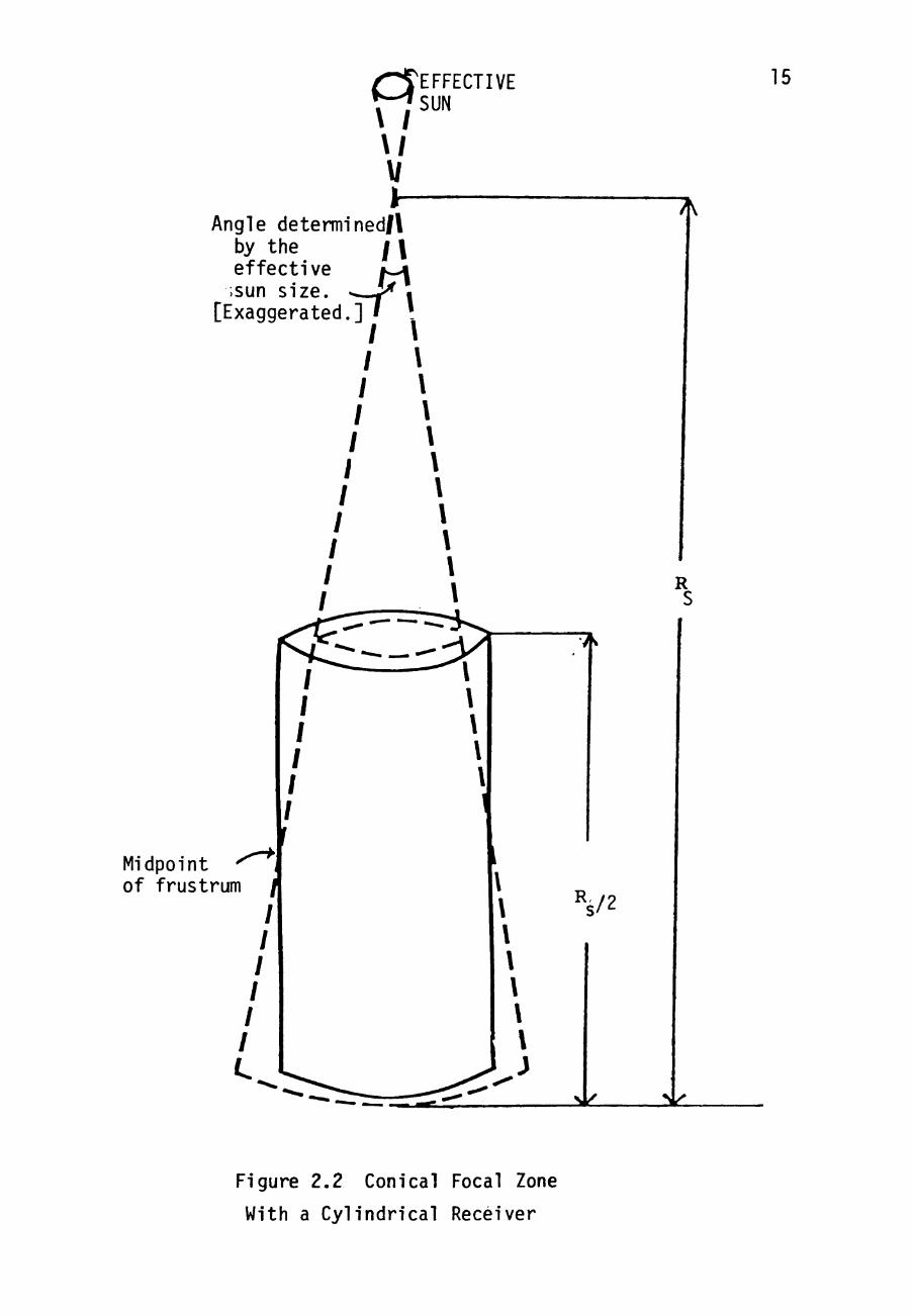
energy from the collector. To produce high quality steam,
the ideal solar receiver would be in the shape of a conical
frustum, matched to a perfectly spherical collector surface.
However, considerable cost savings can be achieved by the
use of a cylindrical receiver in the proposed Solar Bowls.
This means that some of the solar energy directed to the
conical focal region is not intercepted by the solar
receiver. Such a cylinder is illustrated in Figure 2.2.
[The angle is exaggerated in the figure to illustrate the
nature of the mismatched. ] Because perfect mirrors are not
required, the angulor size indicated in Figure 2.2 is
matched to an "effective sun size." It is convenient to
relate mirror surface imperfections to an effective (larger)
size of the solar disk. In other words, i t is convenient
for design purposes to pretend that the mirror surface is
perfect, but that the solar disk is imperfect; surface
errors are mapped to disk errors, effectively enlarging the
solar disk. It is cost effective to use mirror surfaces
with an RMS surface normal deviation of aDout 0.06°. This
provides a focal zone equivalent to that from perfect
mirrors with an effective solar disk diameter of 1 degree
(twice actual size).
a \ ;
V
Angle detemiined/\ by the / \ effective i ^ ;sun size. -^^ .
pd. 1 1 * [Exaggerated.]
EFFECTIVE SUN
15
7K
R
Midpoint of frustrum
/
/
/
/
/
/
Figure 2.2 Conical Focal Zone
With a Cylindrical Receiver

16 4
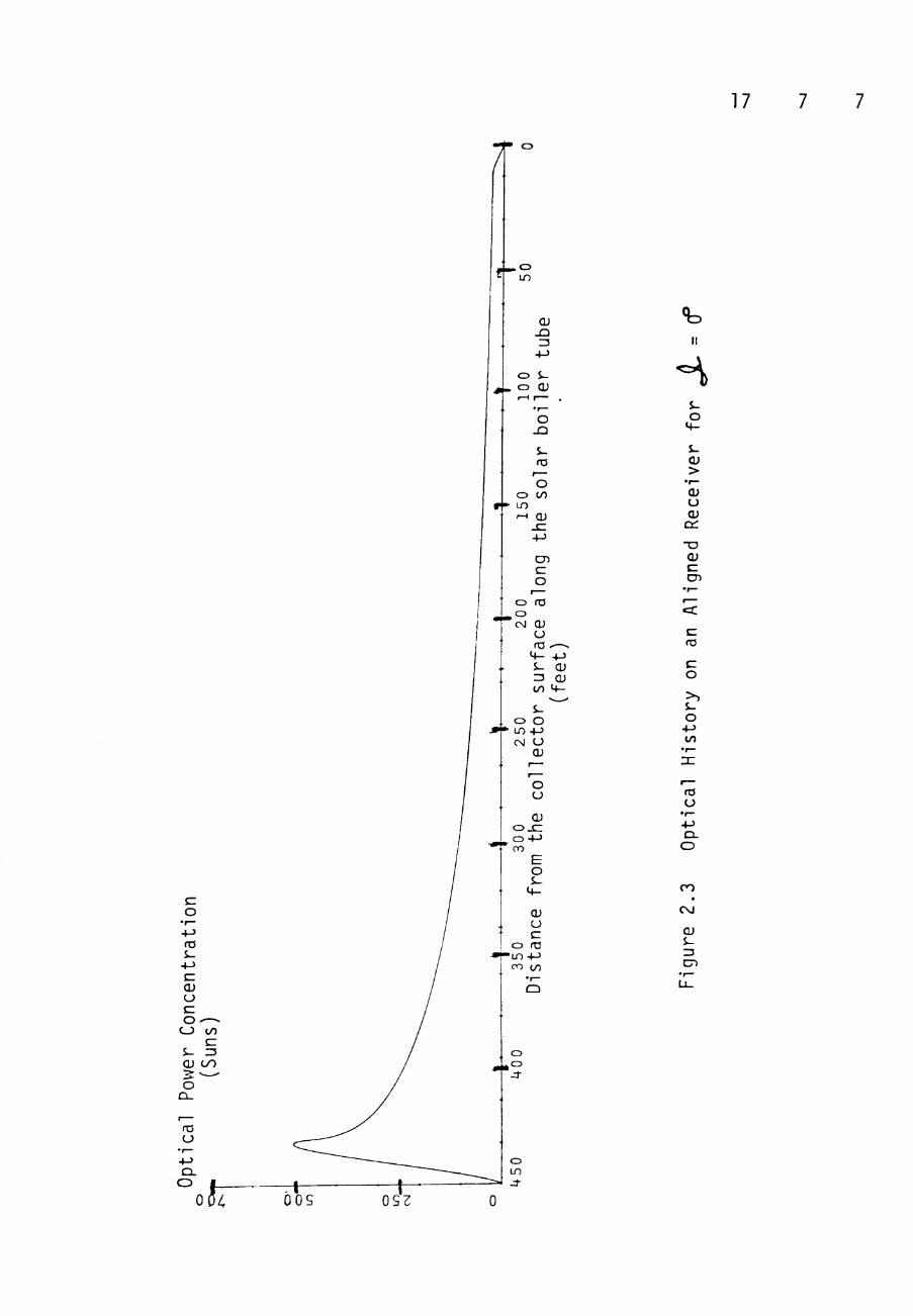
The concentration factor along the length of the focal
region when the sun is aligned with the aperture normal is
shown in Figure 2.3. Notice the low ratios at the end of
the receiver near the reflective surface. Due to lower
concentration ratios in the focal region near the reflective
surface, the mismatch between receiver shape and focal
region does not result in significant losses in total power
capture. Since the cylinder is slightly too large at the
top, the peak concentration is slightly reduced.
The support structure of the receiver is covered by
helically wound parallel tubes which compose the solar
boiler. Water is pumped through these tubes from the
bottom, the end nearest the mirrors, of the receiver to the
top, the end nearest the center of curvature of the Bowl, of
the receiver. The temperature of the fluid exiting the
solar boiler can be regulated by the mass flowrate of the
feedwater.
The position of the sun not only establishes where tae
solar receiver must be positioned, but also the total amount
of sun light which reaches the collector's reflective
I
17
O
+-> fO S-
-M
QJ
o-C_3 to
12 V
o
O t
p-CD Lf)
OJ JD 13
4-)
O S-o OJ r-^ r— .
•r— O
JD
S-03
f —
o O (/) LO r-H CU
J Z +J
en c o
1 ^
CD rO , C 3
CM O) ( J fC '—-
M - +-> S- CU =5 O) to ^ -
S-o O IT) +-) <N O
O) 1 —
r— o o OJ
o x : o +J CO
E o s
M-
(U CJ c
o fC i n + J ro CO
o , o J-
II
%-O
4 -
J-
> o OJ
cc • u cu c CD
ro
c o >> J-o
+-> (/)
«3
u
Q-O
CO
CM
O) J-
C7)
o in
oos 0S2

18
surface. The power en te r ing the bowl depends on the
aperture which the sun sees (Figure 2 . 4 ) . The aper tu re
appears pe r f ec t l y c i r c u l a r to the sun, due to per fec t
alignment along the ape r tu re normal, a t only two moments
during each year . This i s because the sun must not only be
in the proper plane with regard to the time of day
(east-west) , but a l s o in the proper plane with regard to the
day of the year (nor th -sou th) - The angle between the
aperture normal and the ray through the c o l l e c t o r center of
curvature and the cen t e r of the solar d isc in ca l l ed the
inc l ina t ion ang le , v=Jc_ . The aper ture area which the sun
sees i s e l l i p t i c a l most of the time and can be found by:
Aperture Area t he Sun sees
= (the c i r c u l a r aper tu re area) cos J 2 . . (2.1)
The c i r c u l a r aper tu re area has a 200 foot diameter for
the power g r i d i r o n s proposed for the Crosbyton p lan t . The
sub-commercial s c a l e ADVS has an ape r tu re diameter of
65 fee t . The value of Uc depends on the time of day, day
of the year, and l oca t i on and geometry of the Solar Bowl.
The i n c l i n a t i o n angle may be obtained from the formula:

19
c o J-
s-fO
o c/)
<u JZ
m
c\j
S-ZJ
U -

20
cos yJl_ = cos 6 c o s (x-y) COSx + s i n 6 s i n (A-y) (2.2)
where
6 = s o l a r d e c l i n a t i o n a n g l e (from c e l e s t i a l
e q u a t o r ) and i s e s s e n t i a l l y c o n s t a n t f o r any g iven
day [ V a l u e s o b t a i n e d from an Ephemer is t a b l e . J;
X = l a t i t u d e of t h e c o l l e c t o r s i t e (33.625 d e g r e e s
a t Crosyb ton) ;
Y = t h e t i l t a n g l e of t h e bowl , t h e a n g l e t h r o u g h
which t h e a p e r t u r e normal i s t i l t e d s o u t h of
v e r t i c a l ;
T = l o c a l a p p a r e n t t i m e ( t h e hour a n g l e of the sun
wi th r e s p e c t t o t h e l o c a l mer id ian ) .
The S o l a r G r i d i r o n s a r e t i l t e d t o improve a n n u a l s o l a r
c o l l e c t i o n . In t h e n o r t h e r n h e m i s p h e r e a s o u t h e r n t i l t i s
d e s i r a b l e . A t i l t e q u a l t o t h e l a t i t u d e of t h e bowl would
maximize a n n u a l e n e r g y c a p t u r e . At t h e Crosby ton l a t i t u d e ,
a t i l t of 15 d e g r e e s w i l l p roduce 85% of t h e pe r fo rmance of
a c o l l e c t o r t i l t e d t o t h e f u l l l a t i t u d e a n g l e . E f f e c t i v e
cos t r e d u c t i o n i s a c h i e v e d by s e l e c t i n g the t i l t a n g l e t o De
about 15 d e g r e e s .

21
The performance of a Solar Gridiron i s determined by
uncontro l lable f a c t o r s such as so la r pos i t i on , so la r
i n so l a t i on , and wind speed, and a lso by c o n t r o l l a b l e f a c t o r s
such as Gridiron design and maintenance, and mass f lowra te .
All of these f ac to r s are encompassed in the system model
developed for Solar Gridirons by the CSPP. The model i s
used to determine the amount of s o l a r power which i s
t ransferred t o , or captured by the bo i l e r feedwater.
The power captured by a s o l a r bo i l e r i s the amount of
power, Pp, t r an s f e r r ed i n t o the working f l u i d . Dr. L.
Davis Clements and Hariharan Shankar developed a computer
simulation which modeled the performance of Solar Gridiron
Boi lers . This model, r e f e r r ed t o as the Taermal Fluid
Analysis Program, TFAP, takes in to account parameters such
as: wall shape and t h i cknes s , m a t e r i a l s , pressure
var ia t ions , gas a c c e l e r a t i o n , f r i c t i o n f a c t o r s , void
f rac t ions , c e n t r i f u g a l e f f e c t s , l i qu id forced convect ion,
steam superheat ing , and film boi l ing (HS). The TFAP model
uses as i n p u t s : feedwater i n l e t temperature and p res su re ,
wind speed, phys ica l Solar Bowl parameters, d i r e c t normal
inso la t ion , as well as energy concentra t ion p r o f i l e s along

22
the r e c e i v e r . These p r o f i l e s of energy along the rece iver
were ca lcu la ted for various i n c l i n a t i o n angles by the
Approximate Azimuthal Average Approach, AAAA, computer code,
developed by Cr. John D. Reichert and Hipsua Leung (HL) .
Such p r o f i l e s are shown in Figure 2 . 3 . The TFAP model uses
these inputs for var ious mass f lowrates and i n c l i n a t i o n
angles to determine Pp.
Dr. John D. Reichert made "phenomenological" curve f i t s
to the data generated by the TFAP model in 1978 (EC). These
curve f i t s a r e r e f e r r ed to as the TMR equations and are
shown in Appendix A. The TMR equat ions model the power
captured by the f lu id in a so lar oo i le r with five
parameters. These parameters are the Solar Bowl attendance
fac tor , a ( u n i t l e s s ) , the d i r e c t normal i n s o l a t i o n ,
IrjM (KW/m ) , the s o l a r i n c l i n a t i o n angle , ^Jl- (degrees) ,
the wind speed, V (mph), and the mass flowrate of f lu id w
through the r e c e i v e r , M(lbm/hr). The attendance fac tor takes
in to account so lar energy losses which occur before the
energy reaches the s o l a r b o i l e r wal ls . Parameters such as
mirror r e f l e c t i v i t y , f r ac t ion of r e f l e c t o r surface shadowed,
receiver t r ack ing accuracy, and boi ler wall ab so rp t i v i t y are

23
a few of t h e f a c t o r s considered in a - An accura te
" t h e o r e t i c a l " value of a may be pred ic ted for a Solar
Gridiron once the f i n a l design i s complete. The measured
values observed for t h i s a w i l l vary only as tne system
qual i ty parameters change ( i . e . , mirror surface may become
d i r t y , thus decreasing r e f l e c t i v i t y ) . The value of a can be
considered as a very slowly varying function (constant for a
whole day) during normal Solar Gridiron opera t ion .
The a predic ted for the 65 foot diameter bowl at the
aovs was
oiju = 0-686.
For the pre l iminary design of the 200 foot diameter
gr idirons for the proposed p lant
"TH = 0 . 7 2 4
These ca lcu la t ions a re found in CSPP Volume 7. The r a t i o of
the actual a t tendance fac to r for a Bowl to the predic ted
attendance fac tor i s c a l l ed the spec i f i c a t tendance, a . Ihe
24
s p e c i f i c a t t e n d a n c e fo r the ADVS i s u s u a l l y between 90% and
1005i.
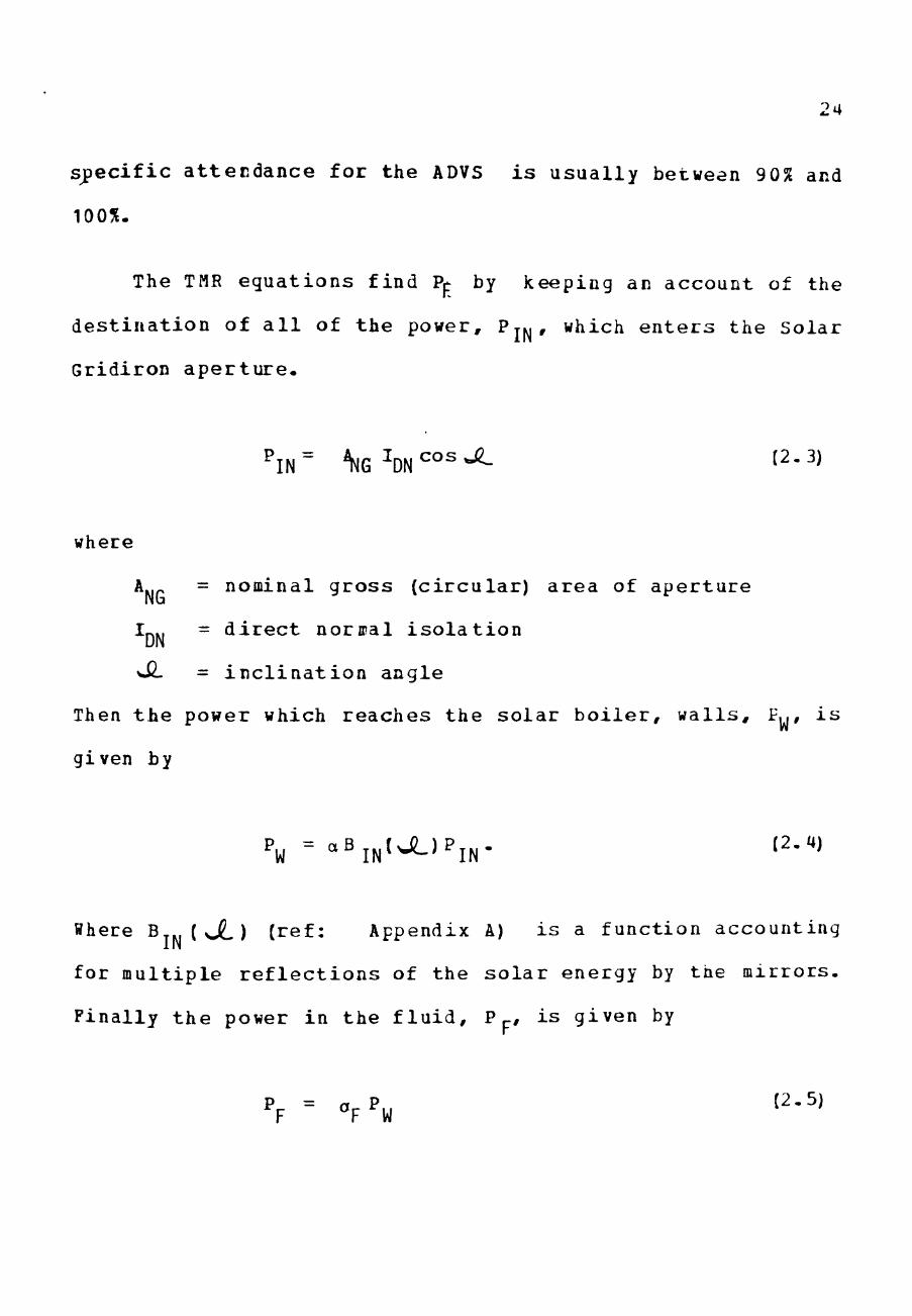
The TMR e q u a t i o n s f ind Pp by keeping an account of the
d e s t i n a t i o n of a l l of t he power, PJM* which e n t e r s the Solar
Gridiron a p e r t u r e .
where
AjP = nominal g r o s s ( c i r c u l a r ) a r e a of a p e r t u r e
Ip,., = d i r e c t normal i s o l a t i o n DN
\SL = i n c l i n a t i o n a n g l e
Then t h e power which r e a c h e s t h e s o l a r b o i l e r , w a l l s , P|,, i s
given by
P„ = a B j ^ , J L ) P i , . (2-a)
Where B ( o2-) ( r e f : Appendix A) i s a f u n c t i o n a c c o u n t i n g
for m u l t i p l e r e f l e c t i o n s of t h e s o l a r e n e r g y by t h e m i r r o r s .
F i n a l l y t h e power i n t h e f l u i d , P p, i s g i v e n by
P = a P J2.5) F " F W

25
where Op is the "fluid power captured factor", a complicated
function which models the solar boiler efficiency. The Or-
factor accounts for the radiative and convective losses of
the boiler.
Figure 2.5 illustrates the dependence of Or on several
of its parameters. For an insolation of 912 W/m , each
curve in the figure represents a different outlet
temperature of the solar boiler fluid. The vertical dashed
line on the graph shows that the boiler efficiency can be
varied, for constant solar insolation and inclination, by
changing the outlet temperature. A change in outlet
temperature is accomplished by manipulating the feedwater
mass flowrate. The management of the value of o^ ^s one
concern in the development of stategies for operation of a
solar electric power plant. The feedwater control in the
process loop must be accomplished in such a way that the
boilers perform as effectively as possible, consistent with
the function of the plant.
Because the performance of a Solar Gridiron system
depends on many uncontrollable factors, an electric power

26 Lf)
CVJ
LO
in C>J U 3
LO
LO
LO
CM LO
LO
LO
CM
LO
CO
LO 32
.
to O)
gre
(de
LO
CM
LO
CM CM
LO
LO
*
CM
LO
LO
CM
c:
CJ
o CO
(/) >
u c <u
•r—
o
o CO
i-
o CO LO
CM
(U S-3
cn
A'ouapL^j.3 jaL.Loa -i LOS
27
plant system must have the support of either an energy
storage capability or a reliable and controllable companion
energy source. The plant which CSPP has proposed utilizes
fossil fuel as a campanion energy source.
A schematic of the proposed Solar-Fossil Plant is shown
in Figure 2.6. There are various ways in which the plant
may be operated. The choice of how to operate the plant
depends greatly upon solar conditions. The path which the
feedvater takes to reach the turbine i s determined by how
the plant i s being operated. A description of plant
operation under various conditions follows.
2-2 Pl nt Operation
Steam for the turbine can be supplied completely by the
solar boilers, or completely by the fossil fueled boiler if
necessary. Typical daytime operation utilizes steam
provided both by the solar boilers and by the fossil fueled
boiler. There are special operational procedures which must
be observed during start up and shut down of the solar
boilers and at nighttime. These special procedures are
described in a subsequent section.

28
c
S -
o a.
$_
>> zc •o (/) o Q . O s -D-
CM
Qi J -
cn

29
2 . 2 . 1 T y p i c a l Dayt ime P l a n t O p e r a t i o n
During t y p i c a l day t ime p l a n t o p e r a t i o n , some
s u p e r h e a t e d s t e a m i s p r o v i d e d by t h e s o l a r b o i l e r s and t h e
r e s t i s p r o v i d e d by t h e f o s s i l b o i l e r . The p a t h of t h e
feedwater can be t r a c e d on F i g u r e 2 - 6 . The f e e d w a t e r f o r
t h e b o i l e r s i s p r e s s u r i z e d by t h e f e e d w a t e r pumps. The
f l o w r a t e t o each b o i l e r i s r e g u l a t e d by v a l v e s c o n t r o l l e d ijy
a computer o r s e n s o r s . Va lves on t h e i n l e t s i d e of t h e
s o l a r b o i l e r s a r e c o n t r o l l e d t o r e g u l a t e t h e t e m p e r a t u r e of
t h e e x i t s t e a m . The f l o w r a t e of f e e d w a t e r t o t n e f o s s i l
b o i l e r i s r e g u l a t e d by a v a l v e which r e s p o n d s t o a water
l e v e l s e n s o r i n t h e b o i l e r drum.
The s t e a m p r o d u c e d by t h e v a r i o u s b o i l e r s i s combined
in t h e steam s t o r a g e t a n k . The tank a l s o p r o v i d e s b u f f e r
s t o r a g e ; i . e . , s e r v e s a s a s m a l l energy s t o r a g e d e v i c e which
wi l l p e r m i t t ime f o r t h e f o s s i l b o i l e r t o i n c r e a s e i t s
f i r i n g r a t e , whenever s o l a r s t eam p r o d u c t i o n d r o p s , w i t h o u t
i n t e r r u p t i o n of t h e s t eam flow t o t h e t u r b i n e .
The f i r i n g r a t e of t h e f o s s i l b o i l e r chaa;^es i n o r d e r
to m a i n t a i n a s e t v a l u e cf t h e p r e s s u r e i n t h e s team s t o r a g e

30
tank. The set-point value is approximately 300 psi above
the pressure required at the turbine inlet. The pressure in
the steam storage tank also determines the pressure of steam
exiting the solar boilers. Thus, solar boiler exit pressure
is determined and regulated by the fossil boiler.
An auxiliary superheater lies in the flow path between
the boilers and the steam storage tank. This superheater is
necessary in crder to control and maintain the temperature
of steam entering the steam storage tank at a set value.
This set-point value i s about 50°F above the desired turbine
inlet temperature. Fossil boiler steam requires the
auxiliary superheater because the boiler itself works to
regulate steam pressure, not the temperature. Solar boiler
steam temperature is regulated by feedwater flowrate
control. However, i t i s more effective under some solar
conditions, due to solar boiler efficiency, Or , to produce
steam at temperatures lower than required by the steam
storage tank. If the solar steam is at tne desired
temperature, it is sent directly to the steam storage taD/..
If the solar steam needs additional heating, it passes
through the auxiliary superheater.

31
The steam which enters the turbine must be finely
controlled. The steam storage tank absorbs many of the rapid
transients in the steam state. The pressure of the turbiiie
inlet steam is fine tuned by the sensor controlled valve
following the steam storage tank. The temperature of the
turbine inlet steam is fine tuned by the desuperheater
preceeding the turbine. Precise control of the temperature
is obtained by a spray of feedwater, at 219°F, into the
steam exiting the steam storage tank.
Finally, steam passes through the turbine-generator
system. The flowrate through the turbine is controlled by a
governor. As the load on the generator varies the flowrate
through the turbine varies. The flow through the turbine
exits at a lower temperature and pressure than i t entered,
but i t is s t i l l steam. The steam exiting the turbine enters
the condenser where i t is condensed and cooled- This
condensate is then returned to the deaerator before i t is
cycled through the plant again.
32
2-1-2 Foss i l Fuel Operation
The p l an t can opera te in a mode in which the f o s s i l
fueled bo i l e r provides a l l of the t u rb ine steam. At such
times, the so la r b o i l e r s may be completely shut down or may
be producing hct water , r a the r than steam. If tae so la r
bo i l e r s a re shut down, during nightt ime operat ion for
example, the feedwater i s p ressur ized by the feedwater
pumps, and sent to the f o s s i l b o i l e r . The flow and i t s
control are ca r r i ed out in the exact ly the same manner as
for t y p i c a l daytime opera t ion , except tha t no steam i s
contributed by the s o l a r b o i l e r s . If the solar iDoilers are
operating as p rehea t e r s for the f o s s i l b o i l e r s , during low
insolat ion per iods during the day, for example, much or a l l
of the f o s s i l b o i l e r feedwater wil l pass through the so la r
boi le rs f i r s t . The water en ter ing the f o s s i l oo i l e r should
be at l e a s t 50°F below s a t u r a t i o n in order to prevent
excessive noise in t h e b o i l e r drum. Therefore, the fluid
exit ing the so la r b o i l e r s passes through the contact cooler
so t ha t the water can be cooled, if necessary, oefcre
entering the f o s s i l b o i l e r . The water i s evdporated and
superheated in the f o s s i l b o i l e r . Less f o s s i l fuel i s

33
required since the water has been preheated- The path of
the steam exiting the fossil boiler is identical to the path
followed when preheating is not available.
2.'1*1 Stand Alone Solar Operation
Only on rare occasions will the plant operate with
steam produced only by the solar boilers. Even when solar
conditions are sufficient for the solar boilers to provide
the required turbine steam load, the fossil boiler snould
not be completely shut off. Unlike solar boilers, fossil
boiler wall materials are not designed to endure frequent
thermal transients. Additionally, if the fossil boiler were
completely shut off and solar steam production was
interrupted, due to clouds for example, i t would take over
30 minutes to bring the fossil boiler up to handle the load.
Such operation would necessitate a huge steam storage
capacity in order to avoid interrupted service. Therefore,
the fossil boiler, should always operate and maintain i ts
temperature, even if i t is producing only a minimal amount
of steam. In the event of a fossil boiler failure, or
during a maintenance cycle, however, the solar boilers could
34
s t i l l opera te if s o l a r cond i t ions warranted. The feedwater
flowrate to the s o l a r b o i l e r s would be con t ro l l ed to
regulate t he steam temperature . The steam s torage tank
would s t i l l be used, and the a u x i l l i a r y superheater would
increase the economy of operat ion if used. The pressure
would be regula ted by the valve following the steam storage
tank ins tead of by the f o s s i l b o i l e r . The steam would flow
through the desuperheater , the t u r b i n e , and in to the
condenser. In t h i s operat ion mode, there i s no back-up for
the so la r b o i l e r s other than the small buffer provided by
the steam s to rage tank . Thus, any i n t e r r u p t i o n s of more
than a few minutes would i n t e r r u p t the p l a n t ' s e l e c t r i c a l
output. The p lan t i s designed to allow stand-alone
s o l a r - e l e c t r i c opera t ion on occasion, but not for basel ine
operation in such a mode.
2.2.JI Special Operat ions
At c e r t a i n t imes spec ia l ope ra t iona l procedures must be
followed to insure smoother system performance. These
procedures do not necessa r i ly have d i r ec t influence on the
p lan t ' s e l e c t r i c a l production, and therefore have been

35
neglected in the r e s t of the s tudy . However, they w i l l be
br ief ly reviewed h e r e . One of these procedures i s required
during the s t a r t up of the s o l a r b o i l e r s every day. ihe
insulat ion of the piping car ry ing steam from the so la r
boi lers has a heat s to rage capac i ty . If these pipes are
cold when steam f i r s t s t a r t s through them, the in su la t ion
will rob much of the s t eam ' s energy before i t can reach the
res t of the p l a n t . This could even r e s u l t in sa tura ted
rather than superheated f l u id reaching the p lan t .
Therefore, t he steam pipes must kept up to temperature a l l
night or must be heated every morning before the so lar
boi lers can provide steam for e l e c t r i c a l production. Tnese
pipes may be heated by passing steam from the f o s s i l bo i l e r
through the pipes and slowly bleeding i t out near the solar
bo i l e r s . Another method of hea t ing the pipes i s t o cycle
solar boi ler fluid through the steam pipes but not in to the
steam s to rage tank (or a u x i l i a r y superheater) u n t i l
superheated steam can be assured. In t h i s case tae so la r
boiler output completely bypasses the turb ine and re tu rns to
preheat the f lu id a t the s o l a r b o i l e r i n l e t . These
operational procedures are i l l u s t r a t e d m
Figures 2.7 and 2. 8.

36
</) <v c
0)
in s -0)
o CO J -ro O
t/7
cn e rC
o CO
to o
CM
$-3 cn

37
1/1 (V c
Qi
t o
J-<v
o CO i-rm
'o
o CD
ro (U zc i.. Qi
O
s -
ro
O to
00
CM
Q} J -Z3
cn

-•^^iSemu^
38
During cold weather a s p e c i a l procedure i s required to
insure t ha t no water f reezes in the s o l a r b o i l e r s a t night .
One method i s to completely dra in the f l u i d out of the so lar
bo i l e r s . A l t e r n a t e l y , warm water can be c i r cu l a t ed through
the so l a r b o i l e r s . There i s a bypass l i ne (not shown in
Figures 2.6-8) through which s o l a r b o i l e r feedwater can be
directed i n t o a heat exchanger assoc ia ted with the
condenser. Such water i s heated by ex t r ac t ing waste heat
from the t u r b i n e exhaus t , thus reducing the work load of the
cooling tower . The heated water can be cycled through the
solar bo i l e r s to e l imina te the danger of f reez ing . i f t h i s
option i s used the cooling tower water c i r c u l a t i o n can be
reduced or even s topped , depending on the amount of steam to
be cooled. This method i s a t t r a c t i v e i f the f o s s i l bo i le r
i s operat ing; i . e . , i f the p lan t i s operat ing a t n igh t . If
the fo s s i l bo i l e r i s not opera t ing , then there wi l l be no
exhaust steam to cool in the condenser. Thus, there would
be no hot water to c i r c u l a t e through the so la r b o i l e r s .
Under freezing c o n d i t i o n , one would then have to c i r c u l a t e
unheated water or dra in the r ece ive r s .

39
These e x a m p l e s of s p e c i a l o p e r a t i n g c o n d i t i o n s a r e
given t o i n d i c a t e t h a t c o m p l e t e p l a n t pe r fo rmance i n v o l v e s
many f a c t o r s — n o t j u s t t h e f a c t o r s d i r e c t l y i n f l u e n c i n g
e l e c t r i c a l p r o d u c t i o n . However t h e a n a l y s i s of p l a n t
performance made i n s u b s e q u e n t c h a p t e r s i s n o t conce rned
with t h e s p e c i a l o p e r a t i o n p r o c e d u r e s .
Z'A The P l a n t Equipment
Only a few p i e c e s of equipment have t o be used in t h e
p lan t t o merge t h e s o l a r s i d e of t h e p l a n t wi th t h e f o s s i l
s i d e . Much of t h e equipment i s s h a r e d by the two s i d e s of
the p l a n t . This i s an a d v a n t a g e of a s i n g l e s i t e with
renewable and c o n v e n t i o n a l e n e r g y s o u r c e s .
The major p i e c e s of equ ipmen t s h a r e d by t h e two s i d e s
of t h e p l a n t a r e : t h e wa t e r t r e a t m e n t complex , the
feedwater d e a e r a t o r , t h e f e e d w a t e r pump, t h e t u r b i n e -
g e n e r a t o r s y s t e m , t h e c o n d e n s e r , t h e c o o l i n g t o w e r , t h e
a u x i l i a r y s u p e r h e a t e r , and t h e c o n t r o l s y s t e m . The
equipment whose s o l e pu rpose i s t o s u p p l y an i n t e r f a c e
mechanism between t h e s o l a r and f o s s i l s i d e s of t h e p l a n t
a r e : t h e s t e a m s t o r a g e t a n k , t h e d e s u p e r h e a t e r , t h e c o n t a c t

40
cooler, and the heat exchanger associated with the condenser
(mentioned in the preceeding subsection) . This leaves the
fossil boiler and flash tank on the fossil side, and the
Solar Bowls on the solar side. Brief descriptions of each
of these major pieces of equipment follow.
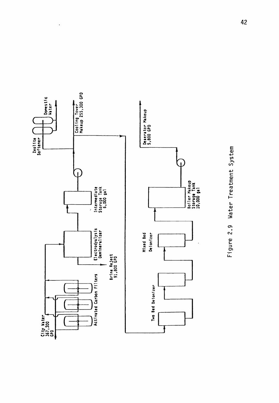
2.3.1 Water Treatment Complex
Service water from the city water supply is used for
make up water for the solar boilers and fossil boiler, to
supply the cooling tower water, and for domestic use at tae
plant site. The water is prefiltered by three charcoal
filters to remove chlorine, iron and rust, and other solids.
All the water is then treated in a demineralizer utilizing
an electro dialysis process. Chemical feeds are eliminated
during this stage. This water is then stored in an
intermediate storage tank.
Some water from the intermediate storage tanK is
utilized in the cooling water tower. In addition, some of
the water from the intermediate storage tank passes through
a softener to a reservoir for domestic services and for the
cleaning the gridiron mirror surface.

4 1
Boilers requ i re a high q u a l i t y water. The in termedia te
storage tank water t o be used by the b o i l e r s passes through
two ion exchange p o l i s h e r s which remove pos i t ive ly charged
ions and nega t ive ly charged ions from the water. This water
i s stored in a 10,000 gal lon tank and i s refer red to as the
make-up water . The water t reatment complex i s i l l u s t r a t e d
in Figure 2 . 9 .
2.3.2 The Deaerator
The deaerator removes a i r and noncondensible gases from
the boi ler feedwater. A s torage tank in the deaerator i s
maintained a t a cons tant water leve l by a con t ro l valve
operated in response t o a leve l cont ro l f l o a t . Therefore,
laake-up water can be added to the condensate from the
condenser to compensate for f o s s i l bo i l e r blowdown and other
system l o s s e s . Ext rac t ion steam from the turbine i s used to
heat the make-up water and condensate in a preheating
compartment. This water i s heated nearly to boi l ing
temperature t o remove the bulk of the noncondensiDle gases.
The water then passes through t r ays t o complete deaera t ion
before going to t he deaera tor s torage tank.
42
c c
•«< o
>•
o o. ca
o »- o > -O u l •— «rt
o> c a.
o -x o — «j a:
Q
E?8
—v
V
0 0 •»-» »^ 0
m o
^ L 1
/ f I i
-/
1
f , I '
f .
ectr
oc
&U
1
i on
F1U
j a
1
i
^
i
1 -m 0
^ «< «
0 • <
GC O O
3
o o. — 1 - 0
— CO
o u>
Q
1- o > ^ » « O
.— o -o • • ^ cn t/> ^^
TJ C w o
5 ^
(U 4->
CO
C
<u E -M ro O) S-
S-
• M ro
CT»
CM
<U S-3
cn
o «> o
o

43
2 .2 -1 The Feedwater Punrs
Three v e r t i c a l , s i n g l e s t a g e c e n t r i f u g a l pumps a r e
mounted in p a r a l l e l under t he d e a e r a t o r . Two of t he pumps
each handle ha l f of t h e feedwater flow for t he f o s s i l and
so lar b o i l e r s . The t h i r d pump i s on s t andby , and
au tomat i ca l ly s t a r t s on l o s s of e i t h e r one of the o p e r a t i n g
pumps. Since the pumps supply both f o s s i l and s o l a r
b o i l e r s , they o p e r a t e a t n e a r l y c o n s t a n t ou tpu t , r e g a r d l e s s
of t he s p l i t between f o s s i l and s o l a r p o r t i o n s . The nominal
o u t l e t p r e s s u r e of t h e pumps i s 1500 p s i a , in o rde r t o
supply the p r e s s u r e drop through the s o l a r b o i l e r s . The
f o s s i l b o i l e r does not have as g r e a t a p r e s s u r e drop as the
so lar b o i l e r s , so t h e e x t r a p r e s s u r e i s dropped a c r o s s a
feedwater va lve in f r o n t of the f o s s i l b o i l e r .
2'!'a The T u r b i n e / G e n e r a t o r System
The steam t u r b i n e o p e r a t e s a t a c o n s t a n t speed t o d r ive
the e l e c t r i c gene ra to r with a cons t an t frequency o u t p u t . A
tachometer on the t u r b i n e works i n con junc t ion with the
turbine governor t o c o n t r o l t h e steam f lowra te so t h a t a
constant t u r b i n e speed w i l l be maintained even under vary ing
generator l o a d s .
44
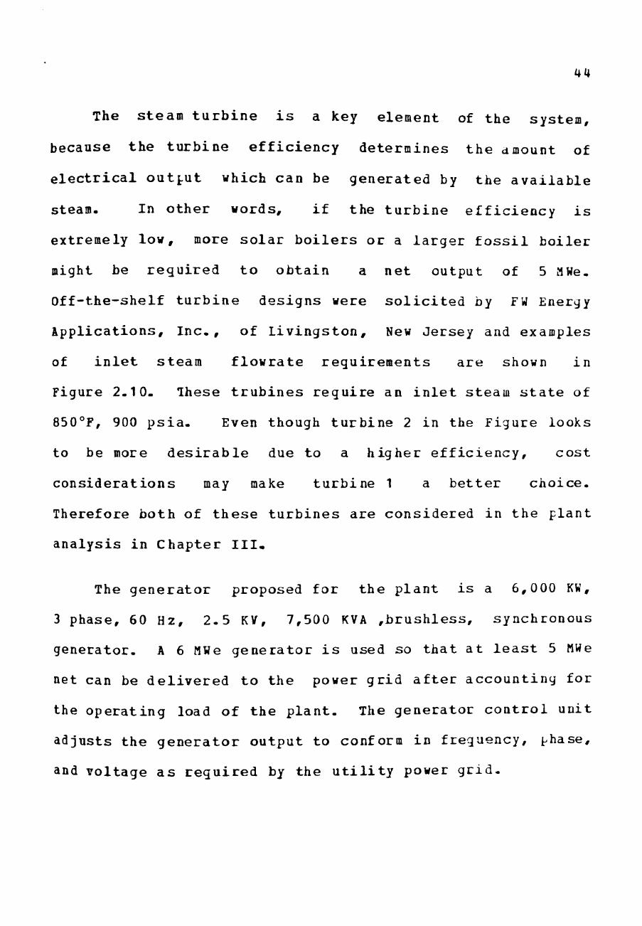
The steam t u r b i n e i s a key element of the system,
because the turb ine e f f ic iency determines the amount of
e l e c t r i c a l output which can be generated by the ava i l ab le
steam. In other words, i f the t u rb ine e f f ic iency i s
extremely low, more so la r b o i l e r s or a l a rger f o s s i l boi ler
might be requi red t o obtain a net output of 5 MWe.
Off-the-shelf t u rb ine designs were s o l i c i t e d by FW Energy
Applicat ions, I n c . , of Livingston, New Jersey and examples
of i n l e t steam f lowrate requirements are shown in
Figure 2.10. These t r u b i n e s requi re an i n l e t steam s t a t e of
850°F, 900 p s i a . Even though tu rb ine 2 in the Figure looks
to be more d e s i r a b l e due to a higher e f f ic iency , cost
considerat ions may make turbine 1 a be t t e r choice.
Therefore both of these tu rb ines are considered in the plant
analysis in Chapter I I I .
The generator proposed for the p lant i s a 6,000 KW,
3 phase, 60 Hz, 2 .5 KV, 7,500 KVA ,b rush le s s , synchronous
generator. A 6 MWe generator i s used so tha t a t l e a s t 5 MWe
net can be de l ive red to the power gr id a f t e r accounting for
the operat ing load of the p l a n t . The generator con t ro l unit
adjusts the genera tor output to conform in frequency, phase,
and voltage a s requi red by the u t i l i t y power g r i d .

45
E JP
O, O o
5 o
-E ta 0) -M to
O)
o
c JO u 3
l="Standard" turbine at 900 psia and 850°F
2=Special turbine at 900 psia and 850°F"
oL 1 2 3 4 5 6
Gross Generator Output. HW a t 0.8 PF
Figure 2.10 Turbine Steam Requirements for Generating Electricity

46
2.3-5 The Condenser
The condenser withdraws steam from the turbine ex i t and
condenses i t by r e j e c t i n g heat to the cooling tower water.
The condensate i s c o l l e c t e d in a hot wel l , a v e r t i c a l tank
located below the main condenser. Two pumps operate in
p a r a l l e l , responding t o a l iqu id l eve l sensor in the hot
well t o con t ro l the flow of condensate t o the deae ra to r . A
third pump i s a v a i l a b l e on standby. The temperature of the
condensate in the hot well i s con t ro l l ed by the flowrate of
the cooling tower water .
2.J.6 The Cooling Tower
The cooling tower cools the cooling tower water. The
flowrate of the cool ing tower water i s varied by a con t ro l
valve to r egu la t e the temperature of the condensate in the
condenser hot wel l . Three pumps pressur ize the cooling
water. Two of the pumps serve as 50% flow pumps, and tne
third pump i s on s tandby.
The cooling tower i s a dual module double-flow tower.
The tower has two 40 Hp 2-speed fans . Cooling water i s
cooled with a i r by r e j e c t i n g heat t o the atmosphere. The
47
cooling tower has a cont inuous blowdown of ^% to maintain
water q u a l i t y . There i s a l s o a 2% water l o s s t o evaporation
and a 0.255 l o s s t o d r i f t . These l o s s e s amount to anout
90,000 Ibm/hr and are compensated with water from the
intermediate s torage tank of the water t reatment system.
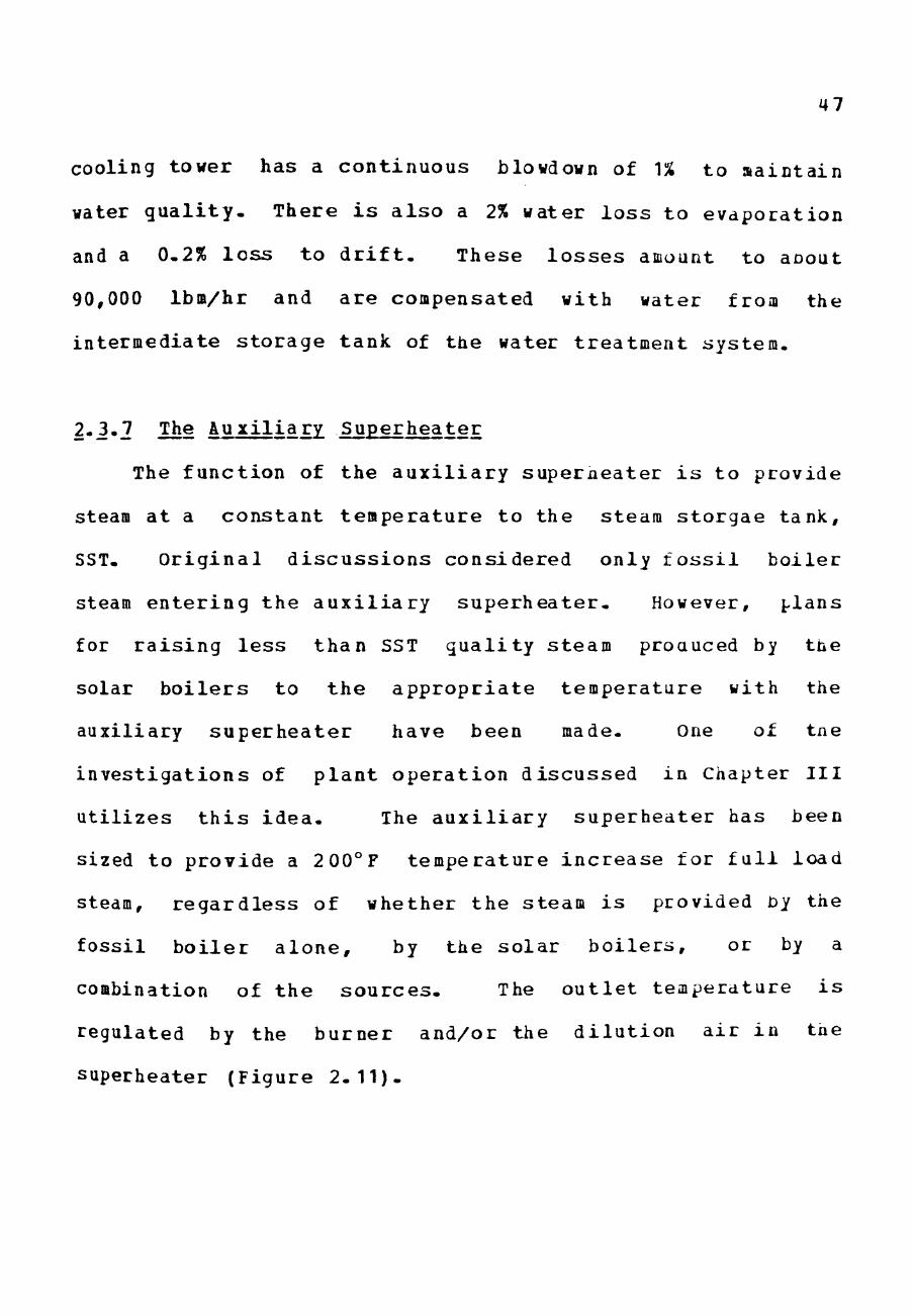
2.3.7 The Auxil iary Superheater
The function of the a u x i l i a r y superaeater i s to provide
steam at a constant temperature to the steam s torgae tank,
SST. Or ig ina l d i s cus s ions considered only f o s s i l boi le r
steam enter ing the a u x i l i a r y supe rhea te r . However, plans
for r a i s ing l e s s than SST qua l i ty steam proauced by the
solar b o i l e r s to the appropr i a t e temperature with the
auxiliary superhea te r have been made. One of tae
inves t iga t ions of p l an t opera t ion discussed in Chapter I I I
u t i l i z e s t h i s idea . Ihe a u x i l i a r y superheater has been
sized to provide a 200°F temperature inc rease for f u l l load
steam, regard less of whether the steam i s provided by the
fossi l bo i l e r a lone , by the so la r b o i l e r s , or by a
combination of the sources . The o u t l e t temperature i s
regulated by the burner and/or the d i l u t i o n a i r in tne
superheater (Figure 2 .11) .

48
Flue Gas Out
Hot Air In
Blower Air Preheater
To Steam Storage Tanks
Gas In
Auxiliary Superheater
- A A A A - ^ -roiD Fossil Boiler
Figure 2.11 Auxiliary Superheater
49
2.3-8 The Steaa Storage Tank
The s t e a a s torage tank, SST, a c t s as a "flywheel" in
the system as we l l as the i n t e r f a c e point of f o s s i l bo i l er
steam and s o l a r b o i l e r steam. The SST maintains a steady
steam supply for the turbine in s p i t e of f luc tua t ions in the
solar bo i l er outputs due to rapid i n s o l a t i o n f l u c t u a t i o n s .
The f o s s i l bo i l e r r e g u l a t e s the pressure in the steam
storage tank at approximately 1175 p s i a . In the event of a
drop in so lar steam production, the steam storage tank has a
capacity of approximately 10 minutes of f u l l load steam.
During t h i s t ime the f o s s i l b o i l e r increases i t s f i r i n g rate
in order to pick up the load, and continues at the increased
f iring rate u n t i l i t has recharged the SST.
2-2-9 The Desuperheater
The desuperheater and the control valve between i t and
the steam storage tank contro l the s t a t e of the steam at the
turbine i n l e t . The valve reduces the steam pressure about
300 psi under normal f u l l load or part load turbine
condit ions. The desuperheater maintains the turbine i n l e t
temperature. I t does t h i s by c o n t r o l l i n g the rate of 219°F
feedwater sprayed i n t o the superheated steam l i n e .

50
2- i - i9 The Contact Cooler
The contact cooler i s necessary because a t t imes the
output from the s o l a r b o i l e r s serves as preheated f lu id for
the f o s s i l b o i l e r drum. The contact cooler i s used to
ensure that t h e temperature of the water enter ing the f o s s i l
boiler drum i s beneath the sa tu ra t ion temperature (531°F a t
900 p s i a ) . The contac t cooler adds b o i l e r feedwater from
the deae ra to r , a t 219°F, to the preheated f lu id in order to
keep the temperature belcw s a t u r a t i o n . The advantages for
operating t h e s o l a r b o i l e r s as feedwater p rehea te r s are
discussed in Chapter I I I .
2-3.11 The F os s i l Boi le r
The f o s s i l b o i l e r , i l l u s t r a t e d in Figure 2.12 i s a
packaged steam genera tor which produces superheated steam
from boi ler feedwater. The bo i l e r has an evaporation
section and a superheat ing s e c t i o n . I t has a dual fuel
system so i t can operate on gas or o i l . Two spec ia l
requirements have been speci f ied for t h i s b o i l e r which are
not normally quoted by bo i l e r manufacturers. The f i r s t
special requirement i s a b o i l e r turndown r a t i o of 12-to-1

51
To Auxiliary Superheater Superheater
Wvn 1
From Contact Cooler
Drum Overflow to Flash Tank
Oil or Gas In
A- From Feed Pumps
Flue Gas Out
i Hot Air
IN
Air Preheater
Fossil Boiler
t^
81owdown to
Flash Tank
Figure 2.12 Fossil Boiler

52
rather than the usual 6 - to -1 quoted for o f f - t h e - s h e l f
turbines. This turndown r a t i o w i l l allow greater fuel
conservation during the t imes when the so lar b o i l e r s can
provide aost of the steam load. The second s p e c i a l
requirement i s a f a s t e r than usual rate of load change for
the b o i l e r . Normally, a maximum load change of 10%/minute
i s quoted by t o i l e r manufacturers. The des igners of tne
proposed p lant have asked for a larger rate of change so
that steam s torage can be kept to a minimum. That i s , i f
the f o s s i l bo i l e r i s f a s t e r to respond to increased load
demands, which can be very sudden due to f l u c t u a t i o n s in
inso la t ion , then l e s s steam need be stored in order to
provide a s teady steam flow to the turbine . The boi ler
manufacturers have increased the load change rate to
20Vininute through s p e c i a l burners and design. The f o s s i l
boiler can, t h e r e f o r e , increase from a minimum flow of
9000 Ibm/hr, to a maximum flow of 70,000 Ibm/hr, in about
5 minutes. This maximum flow provides not only tae required
turbine i n l e t at f u l l load but can a l s o , s imultaneously,
recharge the steam s torage tank.

53
The f i r i n g ra te of the f o s s i l bo i l er i s contro l led to
regulate the pressure in the steam storage tank. Tne amount
of feedwater entering the b o i l e r i s contro l l ed oy a valve
working i n conjunct ion with a water l e v e l sensor in the
f o s s i l b o i l e r drum. The i n l e t water can be between 219° F
and 531°F. Increased i n l e t temperature reduces the f o s s i l
fuel required to b o i l the water. However, t h i s a l so
decreases the heat a v a i l a b l e in the superheater s ec t ion of
the bo i l er . Thus, the o u t l e t temperature of the bo i ler
steaa w i l l be lower. The aux i l i ary superheater must
compensate with a higher f i r i n g ra te .
A continuous blowdown of about 3% of the operating
flowrate i s required i n the f o s s i l bo i ler - This i s
necessary to maintain water q u a l i t y . The blowdown water i s
about 570°F and i s used to heat the make-up water or the
boiler feedwater in the deaerator.
2'2'12 The Flash Tank
If an exces s of feedwater i s sent to the f o s s i l bo i ler
drum, due to a sudden increase in preheated feedwater from
the solar b o i l e r s , for example, the excess i s sent to the
54
flash tank. This avoids losing the high quality water. The
steam from the flash tank is sent to the condenser and added
to the turbine exhaust steam. The exit water is then sent
to the condenser hot well-
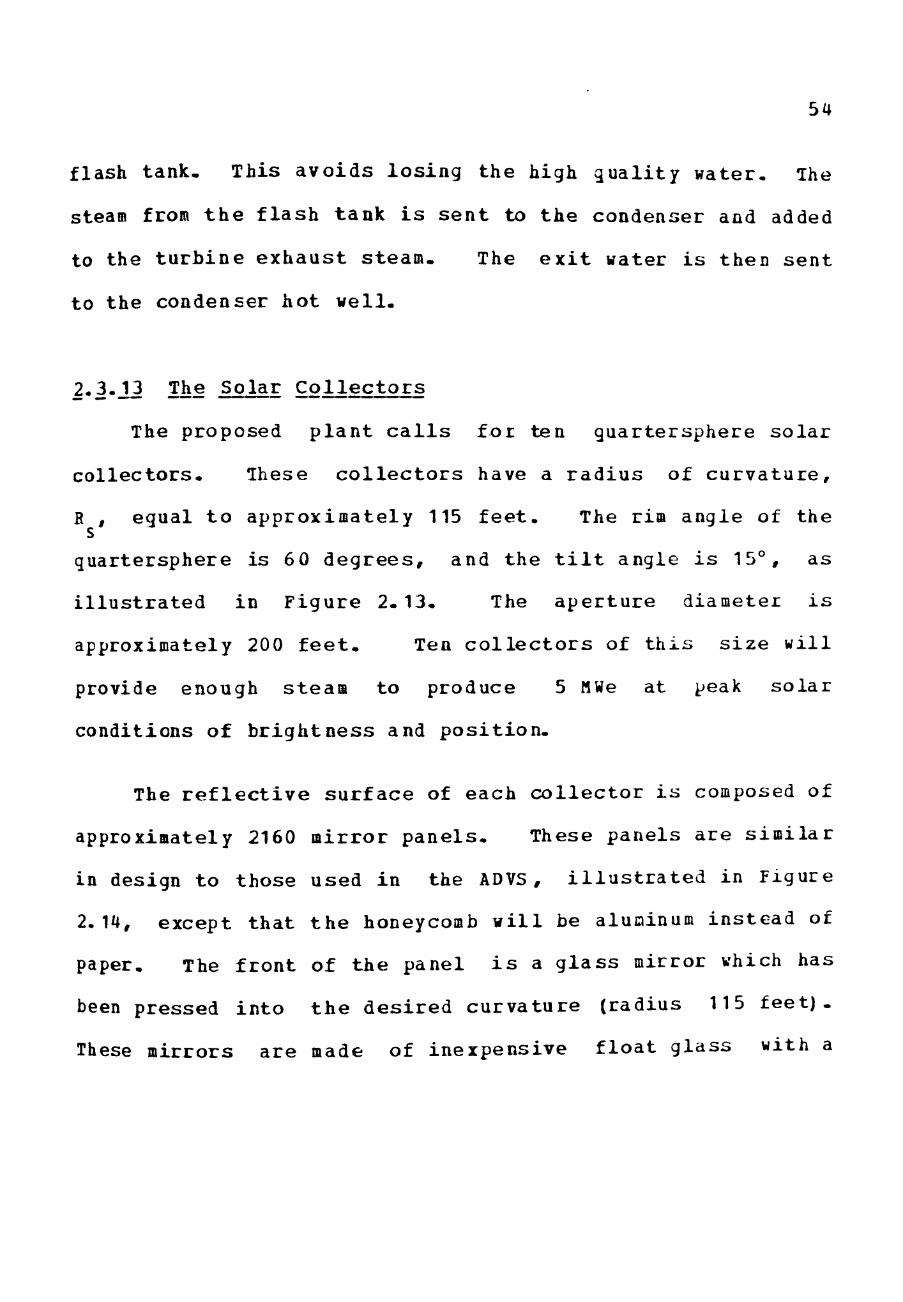
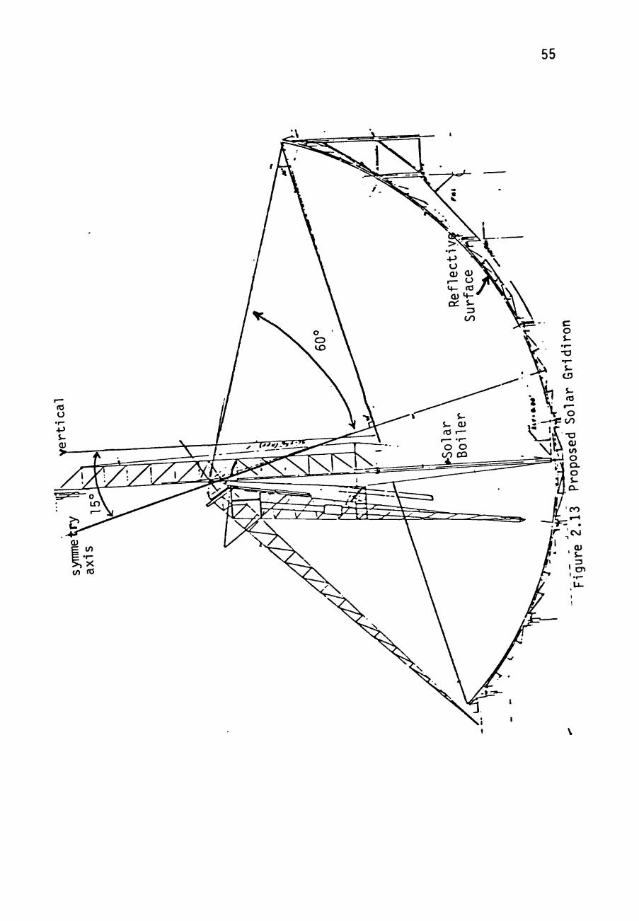
2-3.12 The Solar Collectors
The proposed plant calls for ten quartersphere solar
collectors. These collectors have a radius of curvature,
B , equal to approximately 115 feet. The rim angle of the
quartersphere is 60 degrees, and the tilt angle is 15°, as
illustrated in Figure 2.13. The aperture diameter is
approximately 200 feet. Ten collectors of this size will
provide enough steam to produce 5 MWe at peak solar
conditions of brightness and position.
The reflective surface of each collector is composed of
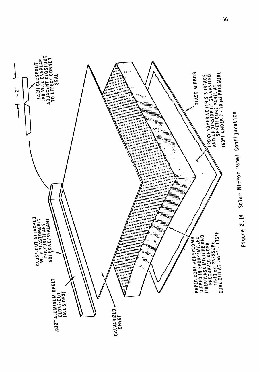
approximately 2160 mirror panels. These panels are similar
in design to those used in the ADVS, illustrated in Figure
2.14, except that the honeycomb will be aluminum instead of
paper. The front of the panel is a glass mirror which has
been pressed into the desired curvature (radius 115 feet).
These mirrors are made of inexpensive float glass with a
55
56
c o
.f—
+J ro $-3 cn
c o o
c ro a. i-o $-
rO
O t o
CM
3 cn

57
s i lvered backing. They demonstrate approximately 88%
r e f l e c t i v i t y . The nirror i s glued to an aluminum honeycomb
structure, which holds the mirrors in t h e i r curved form and
serves as a shock absorber for the mirror. Such panels can
withstand the impact of 1.5 inch diameter h a i l s t o n e s
travel ing i n excess of 100 MPH. This design claim was
tested in the laboratory and substant iated by the panel
performance on the ADVS. The CSPP has proposed an o n - s i t e
f a c i l i t y for the manufacture and r e h a b i l i t a t i o n of mirror
panels.
1-1*11 The Solar Boilers
Twenty tubes , each approximately 445 fee t long, with
0.375 inch outer diameter and 0-25 inch inner diameter make
up each so lar t o i l e r - To reduce c o s t s , the f i r s t 268 f e e t
(portion nearest the r e f l e c t o r surface) i s TP 439 s t a i n l e s s .
This i s the low temperature end of the b o i l e r . A small
plenum then connects the s t a i n l e s s s t e e l tubing with Inconel
617 s t e e l tubing for the l a s t 176 fee t of the tube. The
Inconel tubing i s able to withstand the s t r e s s high
temperatures and thermal cyc l ing which occur near the top of
the rece iver .

58
2.3.15 The Plant Piping
Not a l l of the plant piping w i l l be discussed here, but
the piping and i n s u l a t i o n running between the so lar b o i l e r s
and the c e n t r a l p lant are re levant . This piping i s
s ign i f i cant because the Solar Gridirons are s i tuated at much
greater than usual d i s t a n c e s between b o i l e r s and turbines .
Three pipe l i n € S serve the s o l a r b o i l e r s . One provides the
feedwater. Another c a r r i e s turbine bound steam to e i ther
the steam s torage tank or the a u x i l i a r y fuperheater. The
third c a r r i e s output f l u i d which can more e f f e c t i v e l y be
used as preheated feedwater for the f o s s i l b o i l e r . All of
th is piping i s i n s u l a t e d .
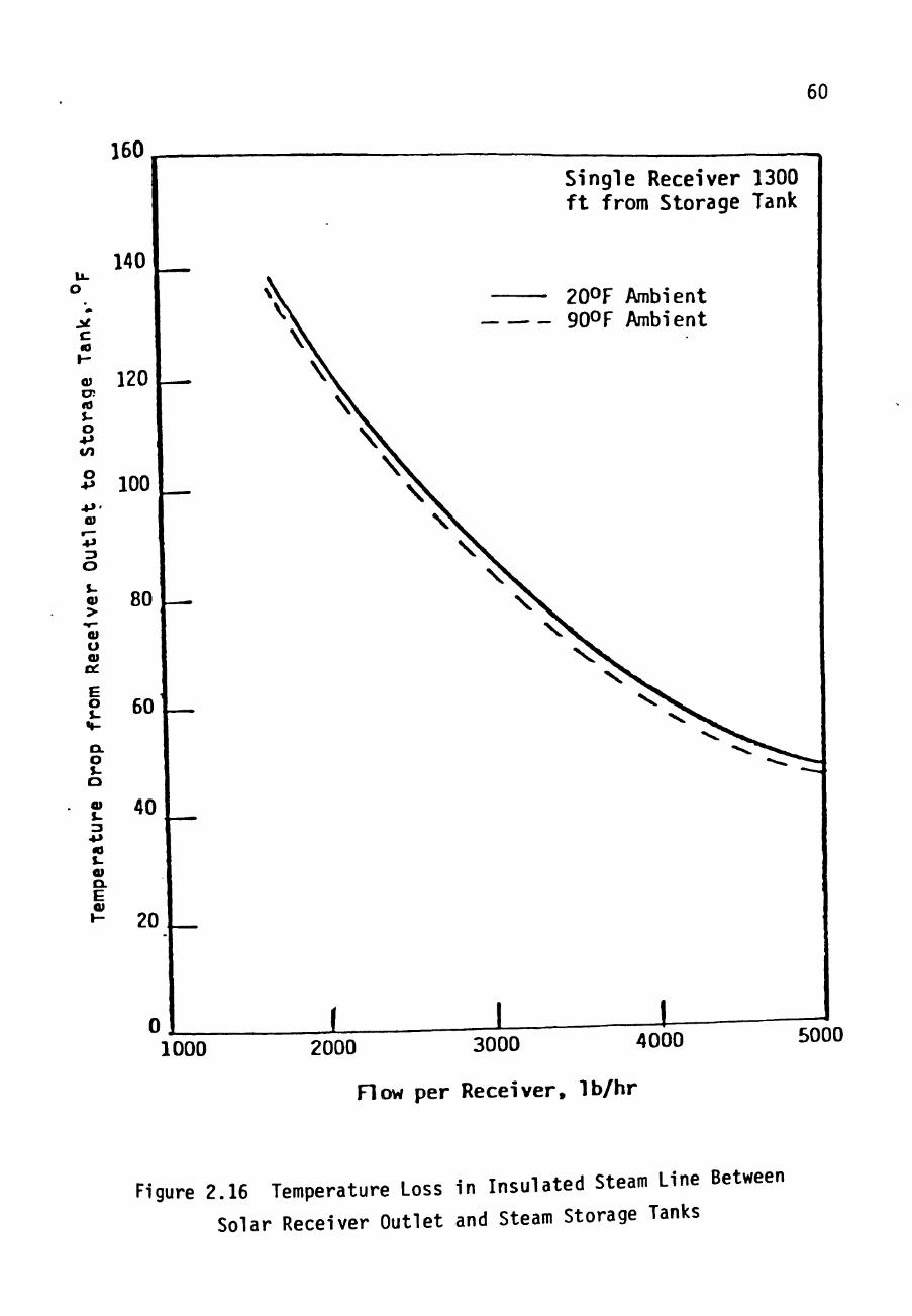
Because the steam pipe l i n e s from the so lar b o i l e r s the
steam storage tank are so long (maximum bo i l er d i s tance:
1300 feet) , the pipe diameters are varied to reduce heat
losses . Figure 2 .15 i l l u s t r a t e s heat l o s s e s to be expected
for d i f f e r e n t pipe diameters and insu la t ion th i cknes se s .
Figure 2.16 shows temperature l o s s e s expected for various
steam f lowrates from the s o l a r b o i l e r s . These l o s s e s are of
special concern because the s o l a r b o i l e r s must be operated
so that the temperature of the steam reaching the steam
storage tank i s above turbine qua l i ty .

59.
c
ro (U
+-> CO
o o o CT>
c •r->> i-i~ ro
<_)
Q) O.
•a <u •*-> ta
3
CO
o
ro
LO
o o O O CM
CM
<U i-
U i - J q / n j g ) adi^j j o ^ooj j a d SSOT ^PSH cn
60
160^
140
Single Receiver 1300 ft from Storage Tank
c to
O! <0 u o
o
o s->
CU
u
E o s-
CL o u o
s.
« S-<u o. E
120
100
20OF Ambient 90OF Ambient
80
60
40
20
0 J _ 1000 2000 3000 4000 5000
Flow per Receiver, Ib/hr
Figure 2.16 Temperature Loss in Insulated Steam Line Between
Solar Receiver Outlet and Steam Storage Tanks

61
The power p lan t b r i e f l y described in the preceding
subsection has been used t o analyze the opera t iona l
considerat ions for a hybrid p lant . The ana lys i s was
performed in order t o optimize the use of the renewable
energy source , the sun , and conserve the conventional energy
sources, o i l and g a s . The procedure and r e s u l t s of t h i s
analysis a re given in the next s ec t ion .

CHAPTER I I I
SOLAR BOILER OPERATION STRATEGY
The S o l a r G r i d i r o n s may be o p e r a t e d i n many modes. A
mode i s d e f i n e d by t h e i n t e n s i v e s t a t e of t h e steam e x i t i n g
the s o l a r b o i l e r ; i . e . , by t h e t e m p e r a t u r e and p r e s s u r e .
For e l e c t r i c power p l a n t s . . due t o t h e n a t u r e of the
r a d i a t i v e and c o n v e c t i v e l o s s e s of t h e s o l a r b o i l e r s , under
some s o l a r c o n d i t i o n s t he b o i l e r may be more e f f e c t i v e l y
used by p r o d u c i n g f l u i d a t l e s s than t u r b i n e q u a l i t y . T h i s
i s why a S o l a r B o i l e r O p e r a t i o n a l S t r a t e g y , S-30S, i s
n e c e s s a r y . A s t r a t e g y d e f i n e s the c o n d i t i o n s under which
the b o i l e r w i l l be s w i t c h e d from one mode to a n o t h e r ; e . g . ,
from a t u r b i n e - q u a l i t y mode t o a p r e s s u r i z e d ho t water mode.
S t r a t egy deve lopment and s e l e c t i o n i s d i r e c t e d toward
maximizing t h e s o l a r p e n e t r a t i o n of t h e power p l a n t .
Converse ly , t he p l a n t must be des igned t o f a c i l i t a t e use o t
s t r a t e g i e s p r o v i d i n g good p e n e t r a t i o n . The s o l a r
p e n e t r a t i o n , a , i s a r a t i o of t h e annua l energy d e l i v e r e d by
62

63
the s o l a r b o i l e r s t o the annual energy required by the
t u r b i n e . Only energy captured by the b o i l e r s which i s
usable by t h e p l a n t i s c o n s i d e r e d in the annual energy
de l ivery- The f i r s t s t e p t o f i n d i n g an o p e r a t i o n a l s t r a t e g y
i s to d e f i n e the modes of s o l a r b o i l e r o p e r a t i o n which can
be most e f f e c t i v e l y u t i l i z e d by the proposed p l a n t .
J - 1 ^h£ So lar B o i l e r Operation Modes
One of t h e advantages of the S o l a r Gridiron concept i s
the a b i l i t y t o produce t u r b i n e - q u a l i t y steam- The
d e f i n i t i o n of " t u r b i n e - q u a l i t y " depends on tae turb ine
s e l e c t e d f o r the p l a n t .
3-1-1 The Qua l i ty Mode
The s e l e c t i o n of a t u r b i n e for the proposed Crosbyton
plant i n v o l v e s h e a t ba lance as wel l a s c o s t a n a l y s i s . FW
Energy A p p l i c a t i o n s I n c . , obta ined pre l iminary b i d s from
turbine manufacturers and analyzed p lan t performance (FW) .
The present recommendation i s a t u r b i n e whose operat ing
i n l e t steam s t a t e i s 850°F, 900 p s i a . This s t a t e
e s t a b l i s h e s , f or p r e s e n t purposes , a lower l i m i t for the
64
temperature of the "turbine-quality steam mode". for
simplicity, this mode will be referred to as the Quality
Mode.
Another factor involved in the Quality Mode definition
is the long distance from the solar boiler outlet to the
turbine (ref: Chapter II). Figure 2.15 illustrates the
nature of losses to be expected from the piping between the
receivers and the steam storage tank. Figure 2.16 presents
various examples suggesting the temperature losses to be
expected. Depending upon conditions, a temperature drop
between 20° F and 140 °F can be anticipated. In the proposed
plant concept, the outlet pressure for the solar boilers is
determined directly by the turbine requirement. In the
guality mode this pressure will be set and regulated by the
fossil boiler. This pressure will be maintained at the
solar boiler outlet regardless of the exit temperature. For
a fixed fossil boiler pressure, the solar boiler modes are
then defined by the exit temperature. As mentioned in
Chapter II, however, the fossil boiler will not serve as the
regulator in all modes. Based upon the turbine and piping
losses, the Quality Bode, QM, for the solar boilers in the

65
proposed p lant i s de f ined t o be 1000°F, 900 ps ia a t the
bo i l e r e x i t .
3-1-2 The Defau l t Mode
I f q u a l i t y mode steam becomes i m p r a c t i c a l because of
high l o s s e s (very low f l o w r a t e s ) , then t h e s o l a r b o i l e r s can
be used a s f eedwate r p r e h e a t e r s for t h e f o s s i l b o i l e r . In
t h i s s i t u a t i o n enough water w i l l be s en t through the b o i l e r s
to assure t h a t t h e e x i t i n g f l u i d i s l i q u i d . Because the
boi l ing t e m p e r a t u r e of water a t 900 p s i a i s 531 °F, the
Default Mode, DM, i s defined fo r o p e r a t i o n of the s o l a r
boi ler with o u t p u t a t (not more than) 500°F. This lower
temperature i n s u r e s a dec rease in the r a d i a t i v e and
convective l o s s e s a t t h e s o l a r b o i l e r wa l l s and, t h e r e f o r e ,
greater b o i l e r e f f i c i e n c y ( r e f : F igure 2 . 5 ) . Under
automatic c o n t r o l , t h e DM i s def ined t o be 500°F, 900 p s i a ,
and the c o n t r o l sys tem w i l l main ta in t h a t e x i t s t a t e . In a
looser s e n s e , a l l e x i t f l u i d which can not be c l a s s i f i e d in
one of t he e t h e r def ined modes (during of t r a n s i e n t
condi t ions , f o r example) i s c a l l e d Defaul t Mode f l u i d and i s
directed t o the c o n t a c t c o o l e r and d e l i v e r e d as preheated
feedwater to the f o s s i l b o i l e r -

66
Based on the discussion above, one might think that the
solar boilers should always operate in the Default Mode so
that the boiler efficiency would be higher due to lower
losses. This i s not the case, however, because there i s a
limit on the flowrate of preheated water which can be used
by the fossil boiler. During peak solar conditions, if all
the solar boilers were to be operated in the DK, at least
three times tec much feedwater would be produced. because
all of this energy could not be utilized by the plant, the
excess would have to be thrown out. Only the energy used
can effect solar penetration.
3.1.3 The Aux iliary Modes
The presence of the auxiliary superheater at the fossil
boiler exit makes other solar boiler operation modes
plausible. Such modes produce steam, but below the
temperature level of the QM- Such steam must be transported
to the auxiliary superheater before entering tae steam
storage tank- Boiler outputs such as: 900°F, yOO psia;
800°F, 900 psia; and 700°F, 900 psia may be used to define
these auxiliary modes, AM. Use of AM's requires greater

67
complexity i n the contro l system for the aux i l i ary
superheater, AS. I f the AM«s are defined i sothermal ly , as
in the examples above, then the AS must respond to a time
varying f lowrate t o d e l i v e r isothermal output to the SST-
Alternately , i f the AM's are defined by fixed f lowrate
s p e c i f i c a t i o n s , then the AS must respond to time varying
in le t temperatures t o d e l i v e r isothermal output to the SST.
A c o s t - b e n e f i t a n a l y s i s i s necessary before committing to
the use of AM's: does the increased solar penetration
jus t i fy the increased complexity and cost of a more
complicated AS and a s s o c i a t e d contro l s? A proper ana lys i s
of the c o s t - b e n e f i t s i t u a t i o n for AM's was outs ide the scope
of the present s tudy .
The goal of t h i s study was to eva luate the switching
function, between modes or s t r a t e g y , for solar boi ler
operation. From t h i s point of view, the greater the annual
solar penetrat ion predicted for a s t ra tegy , the more
desirable the s t r a t e g y . Thus, a method for comparing
penetration was required .

68
3-2 The Annual So la r P e n e t r a t i o n
The annua l s o l a r p e n e t r a t i o n , a , i s the r a t i o of the
annual energy d e l i v e r e d by the s o l a r b o i l e r s t o t n e annual
energy used by t h e t u r b i n e . The energy cap tu red by the
bo i l e r s must be d e l i v e r e d i n t o the QM, the DM, or i n t o an
AM. If too much DM f l o w r a t e occurs (more than can be sen t
to the f o s s i l b o i l e r ) , then t h e excess does not c o n t r i b u t e
to the annua l energy d e l i v e r e d . The p rocedures fo r
p red ic t ing t h e energy r equ i r ed and the use fu l s o l a r energy
del ivered a r e d e s c r i b e d i n Subsec t i ons 3 . 2 . 1 and 3 . 2 . 2 ,
r e s p e c t i v e l y .
I'Z"! The Annual Energy Required by the Turbine
The annual energy r e q u i r e d by t h e t u r p i n e , ALERT,
depends on t h e e l e c t r i c load served by the g e n e r a t o r . The
generator load changes every t ime a sw i t ch i s thrown in the
load g r i d . T h e r e f o r e , a b a s i c assumption necessary in order
to pred ic t ALEET c o n c e r n s the g e n e r a t o r load- The e l e c t r i c
load s c e n a r i o may be assumed t o be almost a n y t a i n g .
However, some assumpt ions a re obvious ly c l o s e r t o what i s
expected of t h e p l a n t . The ALERT for t h r e e d i f f e r e n t annual

69
e l e c t r i c loads was considered. The three loads are: 1)
continuous f u l l l o a d , 6 flWe, supplied by the plant 24 hours
a day, 365 days a year; 2) f u l l load during the so lar
boiler operat ion-hours (defined below) and half load at a i l
other t imes; and 3) f u l l load during the so lar bo i l er
operating hours and no load the res t of the time. Ful l load
i s defined to be 6 MWe so that the plant can operate i t s own
pumps, l i g h t s , and other equipment, and s t i l l supply 5 MWe
net to the e l e c t r i c power gr id .
The meaning of "solar boi ler operation-hours" i s
determined by the Solar Gridiron design, not by i n s o l a t i o n
conditions. The operating time i s es tabl i shed by
considering only the sun»s p o s i t i o n . The sun must be high
enough in the sky so tha t the rece iver can he placed in the
focal reg ion , which l i e s on the l ine determined by the
Gridiron's center of curvature and the center of the so lar
disc. The CSPP Solar Gridiron system has been designed so
that the rece iver can track the sun whenever the i n c l i n a t i o n
angle, ^ , (ref: Eg. 2.2) i s l e s s than 75°. Operation of
the Gridiron outs ide of t h i s angular range would r e s u l t in
very l i t t l e a d d i t i o n a l energy capture. The number of so lar

70
boiler operat ion-hours in a year i s (for J? = 7 5 ° ) a MAX ' •
function of x and y , the l a t i t u d e and t i l t ang le . At
crosbyton, Texas ( ^ = 3 3 . 6 2 5 ) , for a 15 ° t i l t angle , there
are 3585 operat ion-hours i n a year. Thus the s o l a r sytem
Operation-Year = 3585 hours. (3, i)
3.2.1a Continuous F u l l Load
The bas ic d e f i n i t i o n of continuous f u l l e l e c t r i c load
i s : 6 MWe, 24 hours per day, 365 days per year. This
araounts to
(6 flWe) (24 hrs/day) (365 days/year) = 52,560 MWe-hr/year.
This i s a much greater annual e l e c t r i c load than the c i t y of
Crosbyton present ly requ ires . Therefore, i f tne plant i s to
operate e f f e c t i v e l y under t h i s assumption, a buyer for the
excess energy produced must be a v a i l a b l e . The CSPP plant i s
planned to serve a large g r i d , which, in turn, serves
Crosbyton.
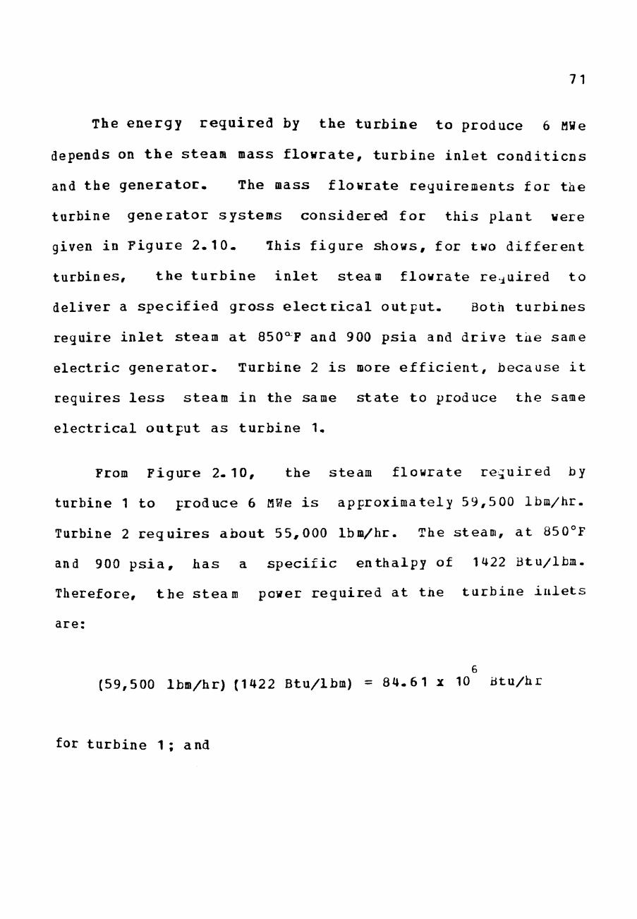
71
The energy r equ i r ed by the tu rb ine to produce 6 MWe
depends on t h e steam mass f lowra te , tu rb ine i n l e t condi t ions
and the genera to r . The mass flowrate requirements for the
turbine genera tor systems considered for t h i s plant were
given in Figure 2 . 1 0 . This f igure shows, for two d i f fe ren t
turbines, the t u r b i n e i n l e t steam flowrate required to
deliver a spec i f i ed gross e l e c t r i c a l output . Both tu rb ines
require i n l e t steam a t 850^F and 900 ps ia and dr ive t a e same
e lec t r i c gene ra to r . Turbine 2 i s more e f f i c i e n t , because i t
requires l e s s steam in the same s t a t e to produce the same
e lec t r i ca l output as tu rb ine 1.
From Figure 2 .10, the steam flowrate required by
turbine 1 to produce 6 MWe i s approximately 59,500 Ibm/hr.
Turbine 2 r equ i r e s about 55,000 Ibm/hr. The steam, a t 850°F
and 900 p s i a , has a spec i f i c enthalpy of 1422 Btu/lbm.
Therefore, t h e steam power required at the turb ine i n l e t s
are:
6 (59,500 Ibm/hr) (1422 Btu/lbm) = 84.6 1 x 10 Btu/hr
for turbine 1 ; and
72
6 (55,000 Ibm/hr) (1422 Btu/lbm) = 78 .21 x 10 Btu/hr
for turbine 2 .
The annual energy required by each turbine is found by
multiplying the power required to produce 6 MWe by the time
6 MWe is to be produced. Therefore the annual energy
required (at the inlet) by each turbine when 6 MWe is
continuously produced is:
6 ALERT = (84.61 x 10 Btu/hr) (24 hr/day) (365 days/year)
12 = C.7412 xlO Btu/year
for turbine 1; and
ALERT = (78.21 x 10 Btu/hr) (24 hr/day) (365 days/year)
12
= 0.6851 X 10 Btu/year
for turbine 2 .

73
3.2.1b Dayt ine F u l l Load - N ight t ime Half Load
In the event t h a t no p o t e n t i a l buyer e x i s t s for any
excess energy produced by the p l a n t , the product ion r a t e
wi l l vary d i r e c t l y with the Crosbyton demand. For the
present s t u d y , r a t h e r than model the Crosbyton demand in
great d e t a i l , a f u l l load demand of 6 MWe w i l l be assumed
for the s o l a r b o i l e r o p e r a t i o n a l hours and a h a l f load
demand of 3 MWe w i l l be assumed f o r the remaining nours of
the year. As mentioned in s e c t i o n 3 . 2 , t h e number of
operat ional hours i n a year i s 3585 hours . There are
5175 remaining hours i n a year .
The power r e q u i r e d at any t ime, by e i t h e r of the
turbines under c o n s i d e r a t i o n , to produce 6 MWe has a lready
been found i n t h e p r e v i o u s s e c t i o n . In the same manner,
using Figure 2.10 a g a i n , t h e steam power required t o produce
3 MWe i s a l s o found. For t u r b i n e 1 t h i s ( i n l e t ) power i s :
(32,500 Ibm/hr) (1422 Btu/lbm) = 4 6 . 2 2 x 10^ dtu/hr
and for t u r b i n e 2 t h e i n l e t power required to produce 3 MWe
i s

74
6 (29,000 Ibm/hr) (1422 Btu/lbm) = 41 .24 xlO B t u / h r .
The a n n u a l energy r e q u i r e d (a t t h e i n l e t ) i s found by
the sum of t h e p r o d u c t s of i n l e t power r equ i r ed and the t ime
t h i s power i s r e q u i r e d . The re fo re , t h e annual i n l e t energy
required fo r the two t u r b i n e s when the load has been halved
at n ight i s
ALERT = (84.61 x 10 Btu /hr ) (3585 h r s /yea r )
+ (46.22 X 10 Btu /hr ) (5175 h r s / y e a r ) 12
= 0.5425 X 10 Btu /year
for t u r b i n e 1; and
ALERT = (78.21 x 10^ Btu /hr ) (3585 h r s / y e a r )
+ (^1-24 X 10 Btu /hr ) (5175 h r s / y e a r ) 12
= 0.4938 X 10 Btu/year
for t u r b i n e 2 .

75
3.2.1c Daytime Full Load - Nighttime No load
The plant is assumed to operate during the solar boiler
operating hours at full load 6 MWe, and no load at night.
While this may or may not be an actual operating procedure
for the proposed plant, there is interest in this limit for
the calculation of solar penetration. This is because a
plant with essentially no energy storage capacity can not oe
expected to have any contribution from solar energy whenever
the Solar Gridirons cannot operate. Therefore, this
approach does not penalize the solar penetration for night
time hours when no solar energy could possibly be collected.
The calculation of the energy required by the turbine
calls for two factors. The power the turbine requires to
produce 6 MWe (ref: subsection 3.2-la) and the time the
plant produces 6 MWe, In this case, 6 MWe are produced
3585 hrs/year- Therefore, the annual energy required (at
the inlet) by the turbine is
6
ALERT = (84.61 xlO Btu/hr) (3585 hr/year) 12
= C.3033 X 10 Btu/year

76
for t u r b i n e 1 , and
6 ALERT = (78.21 xlO Btu/hr) (3585 hr/year)
12 = C.2804 X 10 Btu/year
for t u r b i n e 2 .
3-2-Id Relationship Between ALERT and Energy Consumption
The values for ALERT given in Table 3-1 represent the
energy reguired at the turbine inlets- Not all of this
energy is used by the turbine; some is recovered by the
cycle. In order to evaluate the solar penetration
(ref: Subsection 3.2.3), it is necessary to examine the
thermodynamic cycle and determine the energy used by the
turbine.
As illustrated in Figure 3-1, in the proposed plant
some steam is extracted from the turbine and mixed with the
turbine exhaust to produce 219°F feedwater- The temperature
of the extracted steam, T T ' ^^ less than d50°F, but
greater than 219° F- The work of the turbine is accomplished
across the teaperature difference between the 850 F inlet
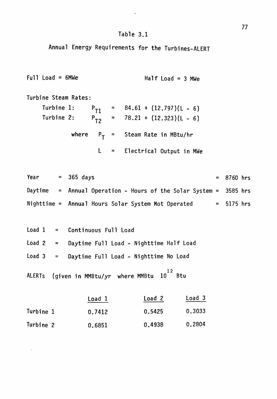
Table 3.1
Annual Energy Requirements for the Turbines-ALERT
77
Full Load = 6MWe Half Load = 3 MWe
Turbine Steam Rates
Turbine 1: P
Turbine 2: Tl
T2
where
84.61 + (12.797)(L - 6)
78.21 + (12.323)(L - 6)
Steam Rate in MBtu/hr
Electrical Output in MWe
Year = 365 days = 8760 hrs
Daytime = Annual Operation - Hours of the Solar System = 3585 hrs
Nighttime = Annual Hours Solar System Not Operated = 5175 hrs
Load 1
Load 2
Load 3
Continuous Full Load
Daytime Full Load - Nighttime Half Load
Daytime Full Load - Nighttime No Load
12 ALERTS (given in MMBtu/yr where MMBtu 10 Btu
Turbine 1
Turbine 2
Load 1
0.7412
0.6851
Load 2
0.5425
0.4938
Load 3
0.3033
0.2804

78
Steam from Desuperheater
m
EXT
Boiler Feedwater
Figure 3.1 Turbine Cycle

79
temperature and t h e exhaus t t e m p e r a t u r e , T ryn- The exhaus t
temperature i s l e s s t han 219° F t o i n c r e a s e t h e e f f i c i e n c y of
conversion of f l u i d energy to usefu l work in produc t ion of
e l e c t r i c i t y .
The net e f f e c t of t h i s c y c l e , however, i s t h a t the
steam mass f l o w r a t e , M , e n t e r s the t u r b i n e at d50°F an i s
re turned a s system feedwate r a t 219°F. Ihe steam r a t e , P ,
(ref: Table 3 . 1 , F i g u r e 2.10) and t h e s p e c i f i c e n t h a l p y ,
h ocn# of 850°F steam a t 900 p s i a may be used t o o b t a i n the 8 50
mass f l o w r a t e ^
"T = ' ' T / ^ 5 0 (3.2)
The t o t a l mass th rough the t u r b i n e i n a year , then , i s
M = ALERT / hg^p , ( 3.3)
and the energy consumed by the t u r b i n e i s :
E = M , r h - h l = ( ^850 " ' 219 \ ALERT
' 850
= ALERT / 1.143 . (3.4)
80
The q u a n t i t y , ^ jn ' r a t h e r than t h e ALERT, i s r e q u i r e d for
the computat ion of s o l a r p e n e t r a t i o n .
3-2.2 The Annual Energy Captured by t h e Solar B o i l e r s
In o rde r to p r o j e c t annual energy c a p t u r e d , AEC, by the
solar b o i l e r s , one must c o n s t r u c t or f a b r i c a t e a b a s e l i n e
year of i n s o l a t i o n and weather da t a for the s i t e - In order
to use, as much as p o s s i b l e , t he a c t u a l ADVS s i t e d a t e ,
severa l Models or E s t i m a t o r s have been devised for
project ion purpose (CP 7 and KW). The t h r e e t ypes of
es t imators which have been cons ide red in p r ev ious CSPP
anaylses a r e :
I . The P r o j e c t e d Operat ion-Day Average (PODA) Model
<p >P0^^ = 365/N I <Pp>j3 (HQPQ /3585 hrs) (3.5a) ^ '^^ N days
I I . The C lea r Sky F a c t o r (CSF) Model
CSF
III. The Statistical Projection (SP) Model

81
SP
<PF^AN,W = <^^F\>M * ^ F f ^ - ^ )
The q u a n t i t i e s <Pp>/\fyj# used i n Eqs . ( 3 . 5 ) , a r e a n n u a l i z e d
average powers ( f l u i d power , n o t e l e c t r i c a l power) added by
the s o l a r b o i l e r s , a v e r a g e d o v e r o p e r a t i o n - h o u r s o n l y . I n
o the r words
(3585 h r s ) <P p>/ f = AEC. (3.6)
The q u a n t i t y <Ep>pj, u s e d i n t he POCA and CSF models , i s t he
average power added t o t h e f l u i d f o r a s p e c i f i c day.
In t h e PODA Mode l , a s e l e c t e d s e t of N days i s used fo r
ave rag ing p u r p o s e s t o g e t t h e a v e r a g e d a i l y energy added t o
the working f l u i d . M u l t i p l i c a t i o n by 365 g i v e s the
p r o j e c t e d a n n u a l e n e r g y i n c r e a s e d e l i v e r e d , and d i v i s i o n by
3585 h o u r s , t h e n , p r o d u c e s t h e power averaged ove r t h e
o p e r a t i o n - h o u r s . The q u a n t i t y ^npj) ^^ ^'^^ number of
o p e r a t i o n - h o u r s i n t h e s p e c i f i c day c o r r e s p o n d i n g t o <Pp ^ -
The CSF Model p r o j e c t i o n i s based on the Pes t days of
o p e r a t i o n e v e r r e c o r d e d a t t h e ADVS s i t e . The q u a n t i t y
'^Pc>nuAv i s t h e l a r g e s t d a i l y power a v e r a g e obse rved from r UjMAX

82
the ADVS s y s t e m . One then argues t h a t the maximum observed
value i s t h e b e s t t h a t the s y s t e m - s i t e - o p e r a t i o n can
ach ieve , and t h i s must correspond to a "very good day of
i n s o l a t i o n " . Other days in the year w i l l not o f f e r as l a r g e
a value for <Pp>nf l a r g e l y because the i n s o l a t i o n i s not as
good. Roughly s p e a k i n g , the CSF f a c t o r , then, i s t o be an
es t imate of t h e p e r c e n t of the time during the
operat ion-year t h a t the sky i s a s c l e a r as i t was at the
ADVS s i t e on t h e day of maximum observed performance
(]L| Ti 955 watts/m^) , assuming that t h e sky i s t o t a l l y
overcast a t a l l t h e o ther t i m e s . Appropriate CSF f a c t o r s
for the ADVS s i t e are probably about 75-803^.
The SP Model i s a g e n e r a l i z a t i o n of the PODA MOdel in
which the s i t e i n s o l a t i o n data i s averaged with a we ight ing
method i n d i c a t e d by the s u b s c r i p t W. A grea t v a r e i t y of
data weight ing methods may be used , depending on the t a s t e
and judgement of t h e u s e r . The PODA Method, l i k e a i l SP
Models, i s b iased by the date w e i g h t i n g . In the PODA
Method, data ga thered on a c e r t a i n day i s used to e s t i m a t e
"the energy t h a t would have been gathered that very day, i f
the s p e c i f i e d s o l a r s t r a d e g y (modes s e l e c t i o n s t r a t e g y ) had

83
been used." Such da i l y energ ies are then given equal weight
over the s e l e c t e d N days . Thus, the PODA Method might be
described as an SP Model employing equal ly weignted dai ly
energies. I t sould be noted t h a t , in a l l cases , a "solar
operating s t r a t e g y ' must be s p e c i f i e d i n order to determine
<Pp>., or <?^>r^ from the i n s o l a t i o n data. S t r a t e g i e s of
operation w i l be def ined and explained l a t e r in t h i s
s ec t ion .
I t i s p o s s i b l e t o include a variance band in SP Model
ca lcu lat ions . The quantity Ap in Equation (3-5c) represents
a standard d e v i a t i o n , a rms dev iat ion from the average.
A.^ = «Pp' > > - [ « P ^ » ' J (3.7)
For the present s tudy , an SP Model was s e l e c t e d . This
i s computed in the usual way: The power was scaled to
represent a s i n g l e "200-foot" gr id i ron , and then multipl ied
by 10 for the s o l a r system of the proposed plant (ten
gridirons) . Power s c a l i n g i s accomplished in an obvious
fashion, using the s i z e - a t t e n d a n c e f a c t o r s .

84
3.2.2a Power Del ivered by the Solar Boilers-Power Tables
Whenever a S t a t i s t i c a l Project ion (SP) Model i s used to
compute an average power for a so lar gridiron system, the
computation can employ a formula of the form:
where P i s a known funct ion expressing the instantaneous
fluid power which would be added by a s o l a r gridiron bo i l er
at a s p e c i f i c va lues of I„,, and ^J2_ under a spec i f i ed DN
solar o p e r a t i n g s t r a t e g y . The average g iven by
Equation (3 .8 ) i s a t ime-averaged power, but the sum i s
ac tua l ly performed over v a r i a b l e s I , and ^J2. which occur DN
in F(Ipjj^, \J2- )r a frequency t a b l e r e p r e s e n t i n g a g iven time
period observed a t the s i t e . The weight f u n c t i o n
F (IHM r sJL ) i s a normal ized j o i n t d i s t r i b u t i o n f u n c t i o n of
IpjM and >JL over some s p e c i f i e d t ime span .
One of the g r e a t s u c c e s s e s of t h e CSPP has been the
predict ion and the v e r i f i c a t i o n of the i n s t a n t a n e o u s b o i l e r
power f u n c t i o n s , P . The P f u n c t i o n s are obta ined from
the TMR e q u a t i o n s , a s e t of curve f i t s t o the output or the

85
TFAP b o i l e r a n a l y s i s code deve loped by the CSPP ( r e f :
subsec t i on 2 . 1 ) . The TMR e q u a t i o n s ( r e f : Appendix A)
demons t ra t e r e m a r k a b l e a c c u r a c y i n p r e d i c t i n g a c t u a l
g r i d i r o n b o i l e r p e r f o r m a n c e , a s has been s t r o n g l y v e r i f i e d
by t h e ADVS d a t a . Th i s a g r e e m e n t i s i l l u s t r a t e d i n
Figure 3 . 2 . In t h e s e f i g u r e s t h e a c t u a l , measured b o i l e r
performance and t h e TMR v a l u e s f o r t he same s o l a r d a t a a r e
e x h i b i t e d on a d a y - l o n g b a s i s f o r t h r e e t y p i c a l d a y s . Such
agreement i s found f o r e v e r y day of o p e r a t i o n ! The TMR
equa t i ons e x p r e s s t h e f u n c t i o n Pp (Irj*^ , ^ #M,Vyj) , where M i s
the mass f l o w r a t e t h r o u g h t h e b o i l e r . I n o r d e r t o use t h i s
func t ion i n E q u a t i o n (3.8) t h e v a r i a b l e s V , and M must be
s p e c i f i e d .
Because i t was not c o n v e n i e n t to c o m p i l e t r i p l e j o i n t
d i s t r i b u t i o n t a b l e s , ^ (Ir,M / ^ ' W^ ' ^^^ J t i n i s ^eed , V^, i s
simply s e t a t t h e c o n s t a n t v a l u e of 15 mph. T h i s f i x e d
value i s v e r y a p p r o p r i a t e fo r t h e Crosbyton s i t e . The
c e n t r a l i s s u e , however , f o r u s ing t h e f u n c t i o n
P (I , > J i , H , V ) i n Equa t ion (3 .8) i s t h a t H must be F DN W
specified as a funct ion of J^^ and ^ . A complete
specif icat ion of M as a function of 1^^ and v^ i s ca l led a

86
a-g l > -J
8 = is
o
g
C <"
si 2
o •t— +-> o
• o cu S -
-a «3
fC +-> <KS
Q
OO > Q
CsJ
ro
cu
<J)
^ g g § g 8 i

87
"solar operat ion s t r a t e g y " . Comparison of s eve ra l so l a r
s t r a t eg ies i s one of the c e n t r a l i n t e n t i o n s of the present
study.
For t h e s t r a t e g i e s considered in t h i s study,
"isothermal modes" were used. In other words, the so lar
boiler feedwater f lowra te , M_, i s cont ro l led to maintain a
specified b o i l e r e x i t temperature , T^ ^ . For such purposes,
Reichert has developed the TMRF equat ions , which allow
simple computation of M as a function of 1-^^ , \JL , T -.-j- , and
the relevant p r e s su re s . These equat ions are accurate enough
that they could be used for open loop control of the ex i t
fluid s t a t e of s o l a r g r id i ron b o i l e r s . The TMRF equations
were obtained d i r e c t l y from the TMR equations oy solving for
the M values corresponding to various values of Pp.
Parametric curve f i t s were then made to the r e su l t i ng values
of H. The TMRF equat ions are given in Appendix B-
Although the TMRF equations are simple to use d i r e c t l y ,
for purposes such as the computation indicated in Equation
(3-8), i t i s of g r e a t u t i l i t y to work ou t , once and for a l l ,
matrices r ep resen t ing P (I^.^ , ^ ) for various values of

80
T . « i t h s u c h " P o w e r T a b l e s " a v a i l a b l e , c o m p u t a t i o n of
<P > from E q u a t i o n ( 3 . 8 ) i s e x t r e m e l y f a s t , and i t i s a
t r i v i a l m a t t e r t o r e p e a t t h e c a l c u l a t i o n w i t h e t h e r
f r e q u e n c y t a b l e s , F ( I p ^ , x X ) , ( r e f : S u b s e c t i o n 3 . 2 . 2 b ) o r
f o r o t h e r s o l a r s t r a t e g i e s ( r e f : S u b s e c t i o n 3 . 3 ) . E x a m p l e s
of s u c h Power T a b l e s a r e g i v e n i n T a b l e s 3 . 2 - 3 . 6 .
The Power T a b l e s shown c o r r e s p o n d t o t h e f i v e v a l u e s of
T - 1000° F , 900 ° F , 800° F , 700° F , and 500°F - r e l e v a n t t o
t h e b o i l e r modes c o n s i d e r e d i n S u b s e c t i o n 3 . 3 . The c o d e
used t o g e n e r a t e t h e s e t a b l e s i s l i s t e d i n Append ix C. I h e
e n t r i e s i n t h e t a b l e s show t h e power ( i n K B t u / h r ) added t o
t h e f e e d w a t e r by t h e s o l a r b o i l e r i n a s i n g l e " 2 0 0 - f o o t "
s o l a r g r i d i r o n . T h i s i s t h e f l u i d power g a i n : e x i t
e n t h a l p i c power m i n u s t h e e n t h a l p i c p o w e r of t h e f e e d w a t e r .
[ " E n t h a l p i c p o w e r " i s mass f l o w r a t e ( i n I b m / h r ) t i m e s t h e
s p e c i f i c e n t h a l p y ( i n B t u / l b m ) . ] The f l u i d power g a i n s were
computed f o r a =95?i (a = 0 . 6 8 8 ) , V^ = 15 MFH,
^OUT ^ ^ ° ^ p s i a , and 1^^ = 219° F .
The 42 r o w s c o r r e s p o n d t o v a l u e s of 1 ^^ from
0-012 KW/m^ t o 1 .037 KW/m^ i n s t e p s of 0 - 0 2 5 KW/ia^. The 15

89
fO
to Q .
O O CT>
II
• • - >
3 O
D_
U -o (J) r— C\J
II
• 1—
o O O o
II
C\J
CO
cu
J:I
I -
+-> Z3 O
h-
(U
JZi
i-(U
o O-
1
a j j -
•iJ •z,-t-^-r^ s r T\ o—sz t.-y ^—-Nj"!-" r,-^o —cDi-«>- - .^ i -^r^* .
O
J * . . „ „ j ; - ;
- J
z>
•
„ - ] ~ - , ^ - r , - ) — . » - i — * - « T ; i ^ - ^ « > - ^ ~ > -O-^O ^rr,0— T O ~ * — 0 5 / ^ - I
IT r>iX>
^ o rf> > * • » r o * " f^l
^ , ^ - : , i ; o * o o < ; < ; o « ; « ; o ^ < 5 o * o * < i i > o o o o o o o o o o o o o o o o o o o o o
*- a

90
ft3
CO O -
o o CT>
II
+-> :3 o
Q-
U -o CD r— CVJ
II
• 1—
.:
rC
• A .
( M S J ^ ' J •>! x '^4 . s f -g 'v j -^ -« - -< -4 • « - . t - < - . - ^ - . - 4 " - ^ ' ^ - « • «
1
^ ' «^ rto J *» A S J«^A«D -^o^—"^ ceo-*"^ o jo—*\ o-s . • - • f > a - 0 - 0 * - * l ' ' X l * ' ^ l N i ^ - « 0 0 ' 9 - D " - ^ O A * r . s — •^»-«0
+J o c: cu i -r3
to J-c;
r ^ • r—
o XJ
s-fO
1 —
o to
o SI \—
c o
•r— •4-' fC c
• r -r— O c
•r— ' ' •
CU to cu
sz •4->
- P 03
(U +J 03 S-CU Q-O
to <U 13
1 —
fO >
c -^-^ O Li- CQ • r - O
•+-> O X «3 CD 'r-
I— cr> "O o c to II cu C -MQ-
•r- :3Q-
- a 1— c: o rtJ o +->
x: to +-> S-cu cu
r - C ^ cr< OJ cu C ^ Di fO i S - —
CO
ro
0 O O cn II
4-> ZJ
o
i A * m ^ - < _ O ? 3 — • * A • n-o-^-< <•? — . - " " ^ A * - "
-XI
or
: i A
(U
J O
CU
JZi «3
(U
o
T O
o z
A - >
I
A ^ o s ) j . ^ - j 4 - A J 5 r > - —'•jy 'A'^iDD
OA Jr^•^/o:^B>"-•''A-r •^ •v i - 'Oy
t
* ^ i : * •
o
A O O C ^ A X O f ^ A S O n AS)-- f»> c
I
.to-
o A A
o r j A . ^ w ' J i-rgosr^iA O ' A ^A<—<o
1 1 ( • 1 ' 1 ' IZ.
»CD O A - T f A - . : J 7 ' t D A lA^»r%-<0 3 • I D C • A * J p - .
>-&
I ^ r
• -v . • A —
• ^ -A T <n
—<f~ A * A r > — • ! » A ' J — 1
" . l A O A
9 CO O A
> • » • » •
t t
r - i A r \
43 J ^ 1A«A - ^ O - i
C D . - « * " ^ -
I
X W A I A
-+-
. ( i V ~ - v r - r » T > o» r - f » » » ^ •
O
? | 2 ! - o o « ; < ^ c ; c ; o o o o c ; c ^ ' o o c ^ < ; c ; ^ o o o o a o o o o o o o o o o o o o

fO
to Q -
CZ» O CTI
II
+-> Z3 O
u_ o (T> 1—1
C\J
II
i •r
• " ^ - • e o AO A(> J-o- »•(^ A X ) - l j > - > . . ^ , , ^ i _
r-p»>r»»-.4.-j>jngwr\J-M-vrj-wW-WW ^Z,Z,..4..,^^Zt-.^2iZi.i
<V
U. O O O 00
! I • • • • • •
.^2'!^':^'i'^*^^'—'o>o-N.-.,•,,Ao-oc^"a-."-AJ•o • r— •o- '>J" i 'M-« ; jy j= -3£^* - i%, -o>-^SoAj -^^ '
OO
CU
XI
•M
O
CU
JD «3
cu
o a.
f-^7 iJ, A":; 2i: i ^ i " - - =•""-^'^'^---^ =^ a A 7-.^-ri: :A
^ *_••_* • . 4 ^ « l ' ^ i i ( ' ^ ' 3 - ; A J - A I \ < - . » . - ) . . * y - ^ r J _ : X I - « A ' ^ rsi — o 3- -^ C l
- *-A fAi\/-«-<o:^oor-« A*-»^-J-l.o^.r.- e A ^ n-.*—•^o"-
- " v - ^ i M C - o n n y ^ j lATi A J -"A•J^-J.-—>^«^X).*^^TO.'^D. '^—c . .
Arf- .AiAA#^^j-^y^-* \ -* i - .Nr-^n.%/.>r>' "•
X
•
X Z
"^'^j*Vi'si'^r>rf—•——•-—•
D i A - ^ a A . - . X l A ' ^ 3 - ' ^ - 4 X A ^ ^ I D A f ^ ' XIArvK>kr^.g01A'Va) A * V f f l ^ l^>tV>V 9\.fCi -o "^"^ *.> o> ^ o A-^K- va>^ ^jv-^^fMcc "n > rv O O »Nf*- ^^ •# 0-4>—'^ • > O) .CIA^OAIO^ «) lAlA'NiO^ ^^rV-AAlO >^"^»Amr\#C 0"^*-O lA'*%AiC
Z « N * r - iA*<n—Oeor» iA* '^ -<» •>r-r^^•^<''0~<D4>'A<n^M>'7'S>«»^.•^A*c HO<0''
^ ; :
X
Z-o
• o o o o o o o o o o o o o o o o o o o o o o o o o o o o o o o o o o o o o o o o

^2
f > > I A » V A > •A J » A - ^ J - - r
f O
to Q.
900
II
out
Ll_ 21
9°
II
i
o O O
II
LO
CO
cu
JQ to
h-
4-> ZJ
o ^-
cu JZl ta
h-
s-cu
o
z o
AiMo«. r v « r » . # > i » ^ . ^ , * ^ J , ^ J - !^!Sk
03
" D CU
- : _3
fO
s-cu
03 r ^
O to
c • 1 —
Q - - 0 O
• 4-»
c cr
w , cu S-03
to S-
cu 1 —
•r—
o J D
i~ <X3
r—
o tn
u
CO r j
r—
• Li_ 0
c n o c ta
c o
• 1 —
-t->
CD
r->.
II
. ^ CO
X • I —
- ^ ^ 3
zxz cxv
ta\—
c •r—
O
c ' I —
cu to
cu • • SZ . c
\- +->
c a
JZ
^ to
a
a. a.
<Z
o +-> i-QJ
13 M -
n >
O C<
- J ; J • •,* • ' ' '
- . : _ : - - . \ . : j ' " j ; *
^ - 2 ^ f ^ ^ ] ' ^ g r ^ ^ ^ ^ = ' > ' ^ « » • ~ - « > = > - 0 • » • • ' - < 3 ' e : . C A r ^ I i , cl _ - ' ^ • ' ^ " • ' - " O - ^ •o»Ay •n-.r.-r- x - ~ o T O - J — 3 * ^ ^ A J - « - \ J ^ >
z ^ - , C ~ — * •-.*»••*-«*— ••—^*/i«—i^^f-i^^i,-' ir» - J -^ r* ~. - ™i cn ^ o*
^'Zt^^*~ * ' ' • » fM-'^O- X > 0 * - * - A - . 0 3 3 0iA t-T»_t3 y - > * i A » r r v - i ~ -'•'"•^'^•*'"«'-»'«•••••» -t •»''Ar>-ir>--.r>m-A-\j.w\j-w ^f.^>-ff-t • — .. T I. •
* - " * * ' ' * - " ^ ^ *•»• -"^c A .H^^«»tvxr>y *o»iA-3 o—r- -v^-ic> * o-
^ * - ' —-y — ^ A x e c A r j y j J5-0-AO-0A. , - - j - o " »-«= r-.«o o. j * ' A * j O ' y » £ A ^px-wo o*- .o>r-"Ai- . tyx ' - iA-x 'A- .oD-- - ««" fn"^.^" "-*".Atr ^ • ^ J r •* ^-» ."-A" ^"A^^i.^'^ ' V ' f - r - i ' I f I -1 I i'
P -'•
z
•c • *
r .O JU3 A-.~^.^<» <|V^^ ^OO'AT-J^-— J i J />rM - iri_i«-fA »a-f—*A • - * ^ ^^ :J
—• *^'*^AiAj-\A-y*^c"i*-*y^'*^»^in^^'^' '»-j->j '*jf ,*^-^-j(
'•O- T Zi P-.~- n > * J O—•r— CO •» O ^"- r - iAX ^r^rf%—..- "^ O-I O A-."^ y ^^<A<AA<oi^»-o»A»A-wO(yr-^uvArw3ty~-^WM»irwo<yr-^»v>». ^ o 1
rv^AiAJ^ AiT 11 .T 9 •* 9 9 Ar"»-A-. -ArA-^^rj- trst-^^'jr.i , - -i, - , - -
•^ X 'Atr?* J " * O'AO'C-^^<v^rMi0AX^'>-fN0 *r»-^o-rf.-rsrf—-^ X * A 9-^ > ^
^ O «MAr L'VaAlAIA-r « « ^ # • • lA-n lA'A lA •A rMr,r^>j.>jr-J-• — , - — • , » .
•>o »« 0-^r-«\r~ A#r-iM^»»vi)t»ia>»A«>»A<y<-ff-* x - a r f \ O i A 3 * \ o w \ — • * - « ^ • Oa>"»iA*A<».y-«)OiAiA/>«0 t>^- ** IA—o«>f-«^*»A».o«)r»iA*r»—•»
fvfC «.%ruA«\aAr>-r • • * • * • • »^'A-A»^-ArV^'*»-VI'^rx-«r»AI'>J-.
» ^ — I «"«.-• x> O-^-^OJ 0 ' A - « « - «'A..ff>^'A.—C OiA—a>^ A.>a>'4>-'v_>-o^' k — • D O ' - . — • O O O O
X Z x - ^ O O C y O O O O O O O O O O O O O O O O O O O O O O O O O O O O O O O O O O O O O

93
-<" - -A» r t 0'>t»* > « - ^ - ^ j i A - . ~ ^ • # j « " . < i ) # o « - < ' » « > A — < - • . A p » , > A ^ 0»V"»-*»> r 3 A - . « 4 »«>» « 3 0-<">.N'O#> A 3 « - < " " AO # 1
to Q .
O O CJ>
II
•^ eO€ a->4 O-* « > * > » - - . O j # o ' ^ r > ' . A > A . » - g 0 O r S • * • — . A r Afw-W o l »'A-> ' 4 - . ^ ' > - j > s o"*»" o 04^ r # A '^x -< -« J j » > a - " ~ o ^ A r r . A ' A x l
o CT»
C\J
II
rA> A>^ O'XS * • D O - . f - • A ( ^ l A O 1A» 3-X » A«- 3 0^"AvAaxf f ' -« -A
• - r r A N - ^ J a - e y x"-a"Xi » I A - > < > J - . j > * ar-0«- . ->JT>Af~»O"VAA o'x>'3-»-r\-e or-y]
+-> 13 O
CL.
L o - ^ O J A > A r - - < / N > # a r M O O »• a> A*~-«<AO'-A~-Al O O <• a> • r f a - « A » - ' * 1 r - . . A C I A P - X - 3 > y : » ' 3 0 - » - . - < A » - > j * e A » » • . . A iA o O - o r - * ~ t o - " y y > ^ 3 " ' " * ; ^ ' ^ i f C ^ ; ?
. j > x ~ o - A r r « n - M ^ o » ' D ~ . o < A i - A i v ^ o y s ' - o x i * ' A > i - " — o y 3 ^ « A x ' ^ ' v .-M A *>-%•*«•»•. A A .n-A I
m
rm«i-<-. s— a A< 9-t f-* » A-AfAA"
o o o LO
1 JAf^AJ-V^rg >><of fM-«->J- . - • -« . ^ - 4 . » - < - • -
ArA
II
ro
(U
+->
o
cu
z o
JZI <a
cu
o D_
7 I M —tA
z
ix: .
? * . - ; : ^ : < : ^ x ^ * - t 7 * A - > A . A A T , A n > * J - M - M J M . V — - — • — -
I
y i ^ ^ ^ A i A ? * 4 - J * 4 - - « - ^ - A - i A m r > A A . - j r v ^ J w - - r ^ — O J - A
£ A »• r - f A y ir
_<AI
o
. 2 - S - j r - . ^ A O . A j y r<y r UJ A J o — a - r — M - ^ O K ^ x T ; ^ ^ 5 A m - J O > - - O ^ A . - . r i y > - - D * i A - . - > c c > - t f N * A , - < y x
" • . a y y - r y 0»A*^
A O A O - A ' _ — a — i s > a A
o;j;o;-:c:^;>:.;—o^^^o^--o-^2-Ar7s?*r;:'^A^ 3 42a3iA^A.' *^^?^^- ' '"^-"" ' '-^"' ' '—'-'"^
tf^>^rr.^--^or«^^--ao^y2-J^;S^S2,l^:i;r^-P£a^«-^-^^ •O a O-0lAW^J•.lf^ Arf> T J-•» * r^-^t^-^'

94
columns c o r r e s p o n d t o v a l u e s of t h e i n c l i n a t i o n a n g l e , UL ,
from 2 . 5 ° t o 7 2 . 5 ° i n s t e p s of 5 ° . These t a b l e s a r e
c o n v e n i e n t l y r e p r e s e n t e d a s m a t r i c e s indejced by i and j :
(^p)ij where i C £ 1 ,42] and j ^ £ 1 ,15] (3.9a)
where
I^^ = £ 0 . 0 1 2 + ( i - 1) (0 .025) ] KW/m (3 . 9D)
and
^ = 2.5 + ( j - 1 ) ( 5 ° ) . (3.9c)
These Power Table matr ices are conveniently used in
conjunction with the Freguency Tables , discussed iu the next
subsection, to compute the annual power delivered by solar
gridiron b o i l e r s .
95
3 .2 .2b F requency T a b l e s - The B r i g h t Eyes T a b l e s
As i n d i c a t e d in t h e p r e v i o u s s u b s e c t i o n , E g u a t i o n (3-8)
may be used t o compute t h e a n n u a l a v e r a g e power c o n t r i b u t e d
by a s o l a r g r i d i r o n b o i l e r . Th i s app roach r e q u i r e s the
func t ion F(Ipj^y s^ ) , a n o r m a l i z e d j o i i n t d i s t r i b u t i o n
func t ion of 1^^ and V»A-. o v e r some s p e c i f i e d t ime s p a n .
The CSPP f o r m u l a t e s and s t o r e s such a f r equency t a b l e ,
c a l l e d a B r i g h t Eyes T a b l e , BET, f o r t h e ADVS s i t e ( co-
l o c a t e d with t h e s i t e of t h e of t h e p roposed p l a n t ) fo r
every day f o r which a_t l e a s t f i v e h o u r s of ADVS o p e r a t i o n
data were t a k e n . U n f o r t u n a t i e y , t he ADVS s i t e p r o c e d u r e s
have been s u c h t h a t 'L.^ , ^JL d a t a i s n o t g a t h e r e d when t h e
r e c e i v e r i s i n t h e " s tow p o s i t i o n " . Al though t h e ADVS has
been o p e r a t e d eve ry day s i n c e J a n u a r y 2 3 , 1980, t h e r e c e i v e r
i s o f t e n s towed d u r i n g p e r i o d s of low i n s o l a t i o n
2
(I < 0.4 KW/m ) • T h u s , f o r a p p r o x i m a t e l y o n e - t h i r d of tne
days d a t a was g a t h e r e d i n t e r m i t t a n t l y f o r a t o t a l r e c o r d
length of l e s s t h a n f i v e h o u r s .
I n c l u d e d in t h e ADVS o p e r a t i o n da t a a r e r e a d i n g s of 1^
and t h e t i m e of day , r e c o r d e d e v e r y 20 s e c o n d s . The va lue
of ^ may be o b t a i n e d from t h e time ( r e f : Eg. ( 2 . 2 ) ) cy

96
c o n v e r t i n g t o l o c a l a p p a r e n t t i m e . To form a BET f o r a
given day , t h e v a l u e s of I and sJL. a r e ave raged over 15
c o n s e c u t i v e r e a d i n g (5 minu te i n t e r v a l s of t i m e ) . The
r e s u l t i n g v a l u e s , ^^nN^ ^"^^ ^ ^^ ^' ^^^ t hen used t o
l o c a t e a c e l l i n t h e same m a t r i x fo rmat used f o r t h e Power
Tables ( r e f : T a b l e s 3 . 2 - 3 . 6 and Eqs. ( 3 . 9 ) ) . In o t h e r
words, c e l l i n d i c e s i and j a r e d e t e r m i n e d suca t h a t
i ^ £ l , 4 2 ] and j ^ £ 1 , 1 5 ] (3.10a)
i > <^DN^/ 0 -0255 K8/m^ > ( i - 1) (3.10b)
j > < yJL >/5° > ( j - 1 ) . (3.10c)
The mat r ix F . . , of s u c h c e l l s i s used t o coun t t h e number of
occu r rences of t h e v a r i o u s <lnM>r ^ ^=^ ^ p a i r s . The F -j
matrix i s i n i t i a l i z e d t o z e r o , and t h e n the a p p r o p r i a t e
element i s i r c r e m e n t a e d by one fo r each 5 minute t ime
i n t e r v a l of d a t a . Such a t a b l e , comple ted f o r t h e e n t i r e
data r e c o r d f o r t h e day i s c a l l e d a UBET, unnormai ized BET.
The n o r m a l i z e d v e r s i o n , t h e BET, i s formed by d i v i d i n g each
t ry in t h e BET by t h e t o t a l number of e n t r i e s fo r t h e day . en

97
There a r e numerous ways t o combine s i n g l e day f r e g u e n c y
t a b l e s to r e p r e s e n t l o n g e r p e r i o d s of t i m e . I f one s imply
adds t h e n o r i a l i z e d BET m a t r i c e s f o r a number of days and
d i v i d e s by t h e number of d a y s , t h e r e s u l t i n g BET c o r r e s p o n d s
to " e q u a l l y w e i g h t e d d a i l y a v e r a g e p o w e r s " . I f , i n s t e a d ,
one a v e r a g e s n o r m a l i z e d BETs f o r a number of days with
averaging w e i g h t s based on t h e c o r r e s p o n d i n g
o p e r a t i o n - d a y l e n t h s , t h e n a PODA Model r e s u l t s
( ref : Eq. ( 3 - 5 a ) ) : " e q u a l l y we igh ted d a i l y e n e r g i e s " . I f
the OBETs f o r a number of d a y s a r e added and, t h e n , the
r e s u l t i n g TIBET i s n o r m a l i z e d , t h e n one h a s " e q u a l l y weighted
5-minute d a t a i n t e r v a l s " . T h e s e , and a l l o t h e r DETs, a r e
biased in one way o r a n o t h e r , as a r e a l l e f f o r t s t o
" c o n s t r u c t a t y p i c a l y e a r " .
For t h e p u r p o s e s of t n e p r e s e n t s t u d y , t h r e e BETs were
assembled, a l l by add ing d a i l y UBETs and n o r m a l i z i n g the
f ina l m a t r i x . The f i r s t , c a l l e d t h e " a n n u a l f re- juercy
t ab l e " was coirposed by add ing a l l of t h e UBETs from t h e 242
a v a i l a b l e d a y s be tween March 1, 1980 and March 1, 1981- The
second, c a l l e d t h e " F e b r u a r y , 198 1 f r eguency t a b l e " was
composed i n a s i m i l a r f a s h i o n from the a v a i l a b l e days from

98
t h a t month. The t h i r d , formed i n t h e same f a s h i o n , i s
c a l l e d t h e "December , 1980 f r e q u e n c y t a b l e " . These t n r e e
BETs a r e shown i n T a b l e s 3 . 7 - 3 . 9 . These BETs a r e r a t h e r
d i f f e r e n t from e a c h o t h e r , o f f e r i n g d i f f e r e n t p e r s p e c t i v e s
on the ADVS s i t e i n s o l a t i o n c h a r a c t e r i s t i c s . The d i v e r s i t y
of t h e s e t h r e e e BETs i s used to check the c o n c l u s i o n s
reached i n S u b s e c t i o n 3 - 3 -
Osing ( n o r m a l i z e d ) Bet m a t r i c e s o rgan i zed i n t he
fashion i n d i c a t e d by Eqs- (3 .10) and Power Tajj les i n the
format shown i n E ^ s . ( 3 - 9 ) , t h e formula given i n EQ. (3.8)
may be w r i t t e n :
42 15 P - .
<P > = .1 I ( p ) . . F . . = JTLIP'CM • (3.11) F i«l j=l ^ F'lj i j ^^ \ F [
The l a s t form shown p r e s e n t s t h e c o m p u t a t i o n a s e v a l u a t i n g
the t r a c e of t h e p r o d u c t of one of t h e m a t r i c e s witn t ne
t r anspose of t h e o t h e r -
I f t h e Power T a b l e m a t r i x i n E g u a t i o n (3.11) i s t aken
to be an " i s o t h e r m a l e x i t s t a t e " t a b l e , such as one of t h o s e
i l l u s t r a t e d i n T a b l e s 3-2 - 3 - 6 , t hen t h e a v e r a g e power
evaluated would c o r r e s p o n d to a " s i n g l e mode s t r a t e g y " .

99
^ • • " ; » - « ' ^ ^ » * - « . * # ^ ^ i A O O - . i a n o J 0 0 3 3 0 j o o o o v ^ a o o o a J o o a o o o o o o o S o o o o o o o o o o
0 3 .oo.ooooooo„,.ooooooro^^4SSS^SSo^^^^^^ - oooooo^oooo D^a :,oooo ooo^oooo'o*^ Jooo'ooJoo^o'oo
C 5 - . ^ i ^ i * " * A>^>,A » ••#rf»«V-AAI'w-..A-<-«3-..«-n'A A
CO CJ)
u i-03
I
o 00 cn
I ^ •
ro
cu r— JD <a
o u to
s: S-
o M-
CU
JZi ta
>) o c cu zs cr (U S-
03 ZJ c c <
' " ^ ^ ..^.^.Ai.—_ ^ o ^ o o o ^ o o o o o a o o o o o o o o o o o o o o o o a a _. 0 0 ^ ^ - ^ 0 0 ^ , 0 0 0 0 ^ 0 3 0 0 3 3 0 0 ^ 0 0 3 0 0 0 0 3 5 o ? S 5 5 ? 3 ? S § 2 S o « 3 0 . > o o o o 3 o o o 3 » » o o * o o o J j < J < ^ a o o J o : J 3 J o o ^ o o 3 0 o o o o
O A r . ^ / - . - . ? S S S S 2 ^ 0 0 0 0 0 0 0 0 O O O O O O O O O O O O O O T O O O O O O ° . ° ^ ° ^ ^ ^ ^ ^ ° ^ ^ ^ ° 0 0 0 0 0 0 0 0 0 0 0 0 0 0 0 0 0 0 0 0 0 0 0 0 0 3 0 0
O O O O O O O O O O O O O o o o o o o o o o o o o o o o o o o o o o o o o o o o o o o
A<(y A•Ai^^ # a «a-'->'v^OA«-o-^—».x>< # A'«4r-A.#-A'^-MX a . . A a # O O " > 4 A f ^ r ^ a a A A i > d - ^ - \ « _ . _ - , 0 o O O O 0 O 0 0 0 0 O 0 0 0 0 0 0 0 0 *
_ _ _ _ „ o o o o o o o o o o o o o o o o o o o o o o o o o o o o o o o o o o o o o o o o o o o o o o o o o o o o o o o o o o o o o o o o o o o o o o o o o o o o o o o o
o o o o o o o o o o o o o o o o o o o o o o o o o o o o o o o o o o o o o o o o o o o
o o ^_^_^ „^
o o o o o o o o o o o o o o o o o o o o o o o o o o o o o o o o o o o o o o o o o o o
o o o o o o o o o o o o o o o o o o o o o o o o o o o o o o o o o o o o o o o o o o o O * * * '0>iAa.ao'AA'na»'no'~s».>« 's iASiAO'>9r>r^>A^.r a ^ . , ' - e s A o-«rAa>o«>f« c ^ * \ A - < n — — » - . « _ , o o o o o o o o - < o o o o o o o o o i o o o a
•j% o o o o o o o o o o o o o o o o o o o o o o o o o o o o o o o o o o o o o o o o o o o o o o o o o o o o o o o o o o o o o o o o o o o o o o o o o o o o o o o o o o o o o o o o o o o o o o o o o o o o o o o o o o o o o o o o © o o o o o o o o o o o o o
"*«>A- -•a•~ -oa'»* A .- #»-.^a3>/^'«sr-'^i> ( a»oo' r->-A'A#09'ly'/t 0-**Off-a>r- a'~<N.r<M—...o-«-<oooot: 0-<0 00 0 0-«000000-<00« o o o-< oooo ooooo ooootaoooo ooo ooo ooooooooooooo
o o ooo ocooooooocooooo.io ooooo ooooo oooo ooooo oo ooooooooo ooo ooooo ooooooooo ooo ooo oo ooooo oooo
.A.-v
IK
z o
z.-< — 1 ^
C\,"
uo CXJ CvJ
II to
u o
JO
BO>A.^i>inr-OOa'V9>A»- '>4- .—•^-•^KMOeoa-.s.~aD•~lA^-«v—•0<^9-<>.0- . -4# ' « a a ' v ^ a > a « a ^ A ^ , ^ ^ - . . . ^ . 4 0 - ' - ' - . o o - ^ o o o o o o - ' - 4 " o 3-'-'—••^-'—' o o — — t - ^ O o o o o o o o o o o o o o o o o o o o o o o o o 0 0 0 0 0 0 0 0 0 0 - .
o o o o o o o o o o o o o o o o o o o o o o o o o o o o o o o o o o o o o o o o o o o
o o o o o o o o o o o o o o o o o o o o o o o o o o o o o o o o o o o o o o o o o o o
All^^O»••••'A^^<^Ai>-A(^^A>•^•^-a»f—^-lA a a a > r f \ 9 . o a a ' ^ • • •A* .#^»MA*>f^. -«r-a g)'A«] corv ». o s « AIM !>*—•»\.—«_«ooo o o o o o o o o o o o o o o o o o o o o o o a ~ » o o o - < o o o o o o o o o o o o o o o o o o o o o o o o o o o o o o o o o o o o o o o o o o o o o o o o o o o o o o o o o o o o o o o o o o o o o o o o o o o o o o o o . . . . . . . . . . . . . . . . . . . . . . . . . . . . . . . . . . . . . . . . . . .
o o o o o o o o o o o o o o o o o o o o o o o o o o o o o o o o o o o o o o o o o o o
.««.w 00 4>i<.o^>.tA«>i-.—i>-_i-.—o-«oo-'0 o o o o o o o o o o o o o o o o o - . o o o o o o o o o o o o O o o o o o o o o o o o o o o o o o o o o o o o o o o o o
O o o o o o o o o o o o o o o o o o o o o o o o o o o o o o o o o o o o o o o o o o o o o o o o o o o o o o o o o o o o o o o o o o o o o o o o o o o o o o o o o o o o o o
*\^^a^iA.^-^rs<^^-a'^-^f* »aoo•90r f^*^ lA»-^ #rf^•^lAo^*>rf^»A*»A^a'A•a'A —fvA ^ a s> r - . « ' « A r j . ^ . . - > o o o - . o o - ' o o o o - . o o o o o o o o o o o o o o oo* o o o o o o o o o o o o o o o o o o o o o o o o o o o o o o o o o o o o o o o o 3
o o o o o o o o o o o o o o o o o o o o o o o o o o o o o o o o o o o o o o o o o o o
o o o o o o o o o o o o o o o o o o o o o o o o o o o o o o o o o o o o o o o o o o o
.^#s3aoe*^«%a *«>"~'xo» a a a o •*»- »\«>'>**«^'A^iAr-iA^iA»nDA*a* af~ O o o ' ( • A lA a « > n r > i - . > ~ > - . O o o O o o o o O O O O o o O O O o o O O o o o o o OA«
^ o o o o o o o o o O S O J O O O O > 0 0 O ' S O O O o o o o J O o o o ' J O O O O O O ' a
. o o o o o o o o o o o o o o o o o o o o o o o o o o o o o o o o o o o o o o o o o o o ^^ o o o o o o o o o o o o o o o o o o o o o o o o o o o o o o o o o o o o o o o o o o o
»MiA»^ A - ^ - ^ O ^ X - . — • • ^ O a ^ ^ * ^ a * .#• "> ^ ^ "A Al».( AJ fSJ ^ ^ « > n « ^ . « i A « A ' ^ a - . 9 'oo—"VIA a a A».N»>«<>,-.——ooo o o o o o o o o o o o o o o o o o o 0 0 0 0 0 0 - .
«\ o o o OOOOO OOO OOO OOO o o o O O O O O O O O O O O O O O O O O o o o o o • o o o o o o o o o o o o o o o o o o o o o o o o o o o o o o o o o o o o o o o o o o o
. . o o o o o o o o o o o o o o o o o o o o o o o o o o o o o o o o o o o o o o o o o o o
cu JD
E Z3
03 +-> o
o o o — ' A rf^*^^^'>.——.—o o o o o o o o o o o o o o OS o o o o o o o o o o o o o — j o o o o o o o 3 0 0 0 0 0 0 o o o o o o o O o o o o o o o o o o o o o o o o o o o o
. 0 0 0 0 0 0 0 0 0 0 0 0 0 0 0 0 0 0 0 0 0 0 0 0 0 0 0 0 0 0 0 0 0 0 0 0 0 0 0 0 0 0 0 o o o o o o o o o o o o o o o o o o o o o o o o o o o o o o o o o o o o o o o o o o o
0..«'tf \«%>Ar>.- .—tOOOOOOOOOOOOOOOO ^OOOOOOOOOOOOO ^ OOOOOOOOO O o o OOOO o o o OOOOOOO 3 o c o o o o o o o r>c<o > . 0 0 0 0 0 0 OOOOO OOO OOOOOOOO OOO OOO OOO OOOOOOOOO o o o ' S o o € > o o o o o o o o o o o o o o o o o o o o o o o o o o o o o o o o o o o o o < ^oo
^-.^-.x a****^a» >^**'^*' ' • r o o v » • * • • • • < « > • • " ' z - • ' * o o o o o o o o
. O O O ' . _ ^ » V . . ^ ,^-> — » « •«•—•> •<>-A—^ * '
^ • c ; o - o * « i ^ o o * c ; < ; o - , ; < J o o o o o o o o o o o o o c
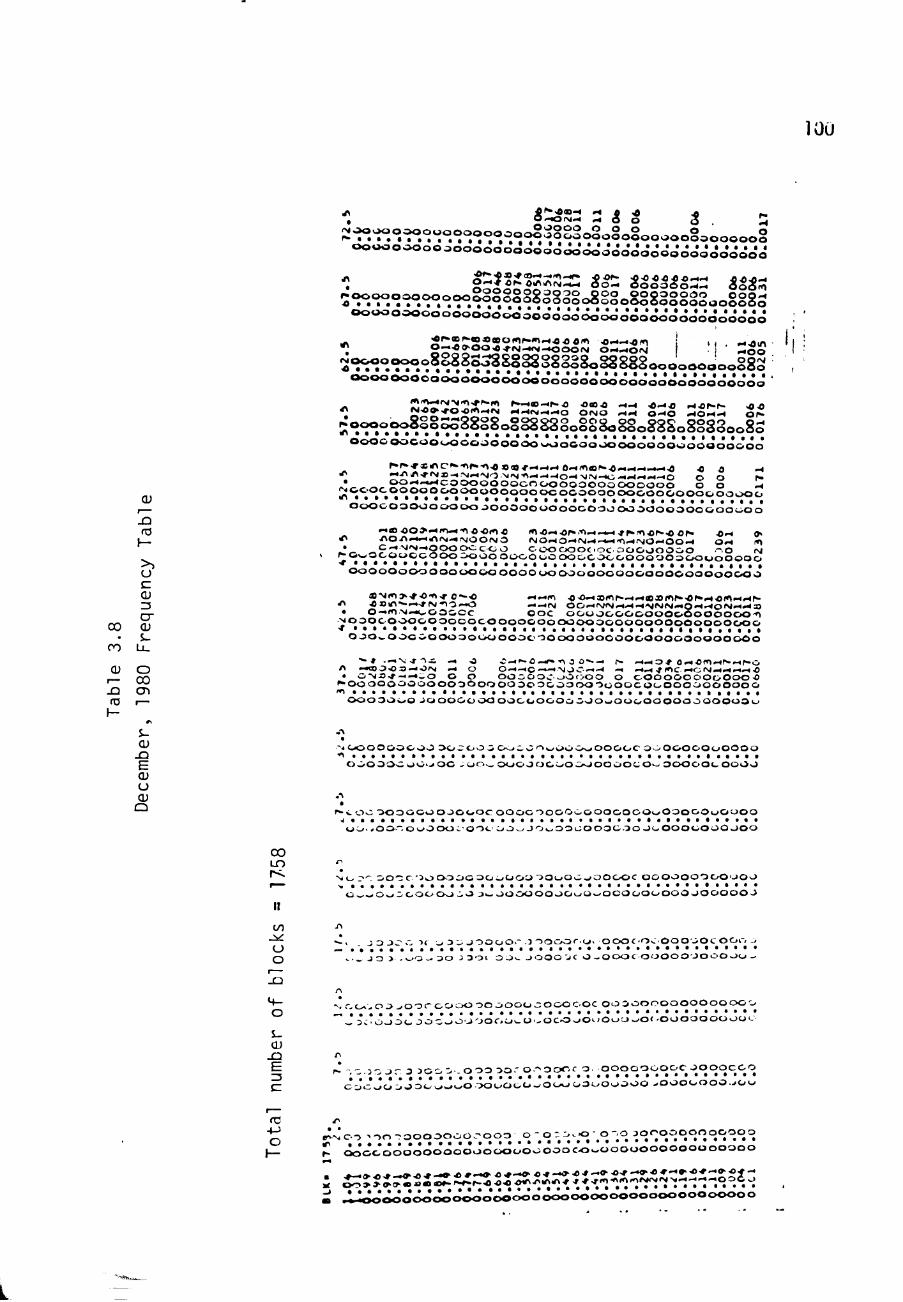
100
^ ^ ^ ' * * ^ "^ J8 * •s f
; 2 V . ^ . ° . ^ . ° ^ « ° < ^ ° o o ^ . O ' : j o i § 2 l o i o § o l o o o o o S o o o o o o § oo«oooooooooooooooooo«i3*<i3*ooo'oo*o*oo'ooo*oo*oooo
•S^.*^.°^.r'.-r^.?2§§§§8g§3§o8§§o§§8§g§g2oo§§§S o o o o o o o o o o o o o o ' o * c J o ' o o o - o c ^ * . ^ * c i i o o o < ; o - o o o * o o o . i o < ; < i
^ IsliSol?^:;;:)::^^^^ i::zt:i j ' i • ::52 2'fi*;°*r^.'^8?2.?S^SS§2§§gS8o§8882ooooooooo§83
t a o o o o o o c o o o o o o o o o o o o o o o o o c x j o o o o o o o o o o o o o o o '
>\ S'^Jt^'^rif'^i'*"'^ ^.-^«-^^•a a a a .^.^ -o-^a i-iaf-r- .oa
rf\ ^
o o o o o o c o o o o o o o o o d o o J o d o o o o o o o o d o o J o o o o o o o o
^r»T«rfNc*.Af»-A<»(0*-«-^-< o-</A«^-a-«.H-4-.—a a a .^ '^^i«>-» ' '^»-«^-< 'NOM'v4AO-t - IO-<>JlM-«0- . -4-«-<—O O O P-(»!«-«-^/-S2^;^?2S202°o<^'^*-^oo=30oooooooo O o -<
|^<=;<^o<^oooooooooooooooocooooooooooooooo& o o o o o o o o o o o o o o o o o o o o o o o o o o o o o o o o o o o o o o o o o o o o o o o
JZl «3 ^ -««>ao>»</A-«Aaa(Aa lAa^^a^'A——.H^r-^ar^-aar* aw »>
I "^ AO.A-.—rfMN<-«iMOOrMO NO.^O-^rg .^ ' - t . - i 'AWNiO^oo .^ 0 . 4 lA J - _ 9 ^ ^ 2 ? ~ * 2 0 o o o c o o c o o o o o c i o c . O O O O O O O O - .o IM
V ^ O i ^ O C O O O C O O O - K J O O O O O O O O O O O C O C / O O O O O O O O O O O O O O O
( J o o o o o o o o o o o O O O O O O O O o o o o o o o o o o o o o o o o o o o o o o o
OJ « N i A > ^ a ' A ^ ©"-•a -<—m aa^smr-—w«sfAr . -or>> i4a i<>>« .4^-13 ' ' aOlA""-—-rPV A O — O — — A( o o —rs/AI>HW>H'NAIIMMO'4-<OI>4.4.^S
cu
cr
CU O CU
0 - « ( n > J — t ^ O O C C C O O C O O U O O O O C O O O O O O O O O O O A QQ _ . ^ o o o c o o o o o o o c o c o o o o o o o o o o o o o o o o o o o o o o o o o o o o
• S- O O O w O O G O O O O O O O O O O O O O O O O O O O O O O O O O O O O O O O O O O O CO u .
"• » , — v j - i i — -a c — f - a —«» A 3 o»--< >. w — o * 0 —a(A»<r» —r»c> QJ O '^ - « O O ^ X —OfM — o O —— O — < N J C — - < -< -<.^-flAC . < 0 ( M - 4 . ^ — a
, rf\ * 0 - v j X ^ - < . . i O O O O O O O O C - > 0 f > 0 0 O O O O O O O O O O O O O O _ ) ~ ^ooooooooooooooooooooooooooooocoooooooooooo
^ CD < A . . . . 1 a ro I o o o o o o o J O O O O O O O O O O O O O O o O O O w O O C / O O O O O O O O O O O o
\-
QJ ^ . O O O O O O O O O o o ^ o o i O O C O ' A W O O O > J O O O O C O O O O O O O O O O O O - Q A
^ ooooOwoo»oc oo._ ooooocooc/oooooco^ OOOooi-OOOO
00 ID
I I
to
A-s. o o O O O a o o o J O O O C o o o c o o o o o o o o o o o o o o o o o o o O o o o
o o - ^ o o " . o o o o o c - o o c o j ^ j o ^ o o u o o o o o o J O o o o o o o o o o o
^ i o ;>^- o o ' : ; c ' i o o o o o o t j o o o o o o o o o ^ o o o o c o o o o o o o o o o o o
. . . . . . . . . . . . . . . . . . . . . . . . . . . . . . . . . . . . . . . . . . . . O w - ' O ^ j . Z ' O O O o o o o J>- O O O O O O O O u O ^ O C O O O O O O O J O O O O O J
^ , J O JJ~ r •>< ;_, 3 ;> J O O O O . " J ~>0C>0(".O' O O O f ' O C O O O J O t o o o ->
Q ^ ._ J o > . . - -O-- J O J 3 0 1 O J ' ) 0 0 0 "JC O - O O O C O O O O O ' J O O O O O --
_Q
JI5
. wo. o j^ooroooooo joooooooooc ooo ooooooooooooo • • • • • * , * • • •
- 3 C. o o o o J O O o O J ' J O C - O ^ O . - O C O J O O O O U ^ O < - O O O O O O O O O ' .
. - - 3 O J - 3 3 O O 0 o o o O O ' o A o o r - r o o o o o o o o o c j o o q c c o
: . . . . . . . . .. • • • • • • • • / • C O O O O J O JO o o o O O O O O O O - . O O O o o o o o o o o ^ o o o o o o o J O O
ta ^ . *
h- r- oooooooooooooooooooooooco^oooooooooooooooo
• ,»—»^^—«'^*—•a*—••a^-^a-r—<ya-r-o-a^—o-a^-o-^^-OKa*--
5 ?^.>>?-22^-*;^^;-.a-.o-^-.-i-V.*.-----'^ i . : J « ; « ; « ; « ; O < J < 5 O O O O O O O O O O O O O O O O O O O O O O O O O O O O O O O O O

101
a> •
00
cu t—
JD <a
JD <a
\— >, o c: cu 13 cr cu S-
u_ r— 00 <J>
. ift A^A/^ w Ain "^ o o o o o o o
i ^ ' ^ " ^ r ^ i ' ^ ° ^ ' ^ ^ ' ^ ^ " ^ . ' ^ i ^ " ^ ° o S o o o o o o o o o o o o o o o o > j o o o o
o o o o o o o - o o o o o o o o o o o o o o o o o o o o ' o o o o J o o o o o o o o o o
. O - J N r A.A>i-«-.0 o O 0-<M • O O O O O O O O - " . ) 0 O <!1 i i /i i^O o o o O O O O O O O O O O O O O O O O O © O O O O O O O O O O O O O O O O O O O O
o o o o o o o o o o o o o o o o o o o o o o o o o o o o o o o o o o o o o J o o o o
iAar>^ift^a)iNr- a'A^^a-* —lAJ lA lA i 4 4 A>n«4w.N •^ O.^A(*»«A.** —0-<-«^ —ooo O iH •-•OO'HIM^ < ^ O O ^ O O O o S § 1 § ^ 8 S i g o g 3 S § 3 o 8 8 S 3 o O § 0 0 0 0 § 0 § : j g § 8 S
O O O O O O O O O O O O O O O O O O O O O O O O O O O O O O O O O O O O O O O O O O
a- * r"> .4Aaar» i c ^ a - ' - ^ lO .^ -^IAIA IA >O a a a lA (Vi»{<l.>:Mar>4 >jrA OA-«'4>4 O ^ r 4 0 0 O -< .<N-« • _ ^ OO-*<-•-«OOOO o o o o o o c o o o o o OOC
p ^ o o o o o o o o o o o o o o o o o o o o o o o o o o o o o o o o o o o o o o o o o o o o ^ o o o O o o o o o o o o o o o o o o o o o o o o o o o o o o o o o o o o o o o
4<7>aa.4-^sai>-<'4'4«4>i.H ,AIA M •^.H aa^^wiA IA m a •TV •«««• WMIVJ 4'A-<0-<»^ —WA«^ o o Al i-<w -4M.4WO O O IM • o o w.N.400wOOOOOOO o o O o o OOOOO o o o
<MOoo o o o o o o o o o o o o o o o o o o o o o o o o o o o o o o o o o o o o o o o ( ^ • • • • • • • • • • • • • a t a v a a a a a a . • • « . • * • • • • • . • • • • • •
(U O .:«oo oooo ooo oooo ooooooo ooo oooo oooo ooooooooo
IMi-«l>r>a3(Aa<-<-4 IAwa .4 .4 i- tA A.4IA lAlAa •Ot\ lA l A ^ a i A N «A T<>4^*ainM.<o o—rM.4-4 .^o O « H O O O > H W O O O W W O A • Qw—•>. - O ' O O CQG^a O O o o o O p O o o O O O O Q Q
r>'Oooooooo o o o o o o o o o OOOOOOOOOOOOOOOOOOOOOOOOO ^ a . a . a a a . a . a l a a a . a . a . a a a a a a a a a a a a . a a a
O O O O O O O O O O O O O o o o o o o o o o o o o o o o o o o o o o o o O O O O O O
Air-Nf~-rf~ lA lAa—oor^aA IA IA^—rf^ IAIAWWIAIAIAIA lAiAiAa ^ ^ A J ^ A r > - ^ O OrvJ—-<w<^—O O o O — o O O W ^ O O O O OOO— • • c-«IM doo o OOOOOOOO o OOOO OOOOOOOO OOOO ^OOOOOOOOOOOOOOOOOoooOOOOOOOOOOoooooooooooo T a . a . a i a . a a a . a . a . a . a a a . a . a a a a a a a . a a a a a . a a a a
o o o o o o o o o>^ o o o o o > w O o o o o o o o o o o o o o o OOOOOOOO o o o o A c a s c ^ a o - H o A — ^-« — - . W , - \ A a A—-«w rtw -«WWA A A A IA
^ ~,«o—."N-^aA —"g-<—o-«-<t;w w-<<Hoo wowNwowAjwwo o o o o . o — ' A N - i O o o ^ o o o o o c o o J O 3 0 o o o o o o o o o o o o o o o
^ ooooooos jo ooooo o o o o o 3 o o o o o OOOOOOOO o o o o o o o o o A a . a . a a . . a i . . a . . a . . . . a . . > a . a . a . . a . . . . » « a a a a
O o o o o o o o o o o o o o o o o o o o o o o o o O O O O O O O O O O O O 3 & 0 0 0
wf-j^.f r><Tir>»,Nr" Aa owar-— IAWO o w w a A w w w a • ^^i-/''iXf-^A'A^(AA.-<-<'J-^fA-^ t>»-4-.-^ -.*^--«0»-4i-*«-. ^
• > ^ a:i-. r-(j.- —ov oooOOOOO oooooooc ioooo ?__* i%0 00--.0 JOOOO J 3000000000000000000000000000000
fO 'OCO 30JO J0~/000 oooooooooooooooocooooooooooo
:3 i - o o o ^ ^MiM o-"aaw-«-<r.-«—aAiA-« oaw— wawwiAa
- Q ir\ —.-^w f A A A-<--J-<wMr>jrr , -«- , iwOo-< NJ—<NJN -Hi-irgwOW m a —in r — — O o o o o J O ' _ > o o o o o o o o o o c o o o o o o o ^ ^ - ^
• ~ P-OC J ^ O ^ O O O ^ O JO O O O O O O O O 3 0 0 0 0 0 0 0 0 0 0 0 0 0 0 0 0 0 0 0 C J , * 3 * 0 0 O J O w O J O J o o o >0 0 0 0 0 - ^ 0 3 0 o o o J OO J O O O 3 0 J O O
• » . « J O W A A lA A — O V r *•.% w O O J
r - ' J J o . ! J J o J o o J - ^ o ' J Jo*o-*o'J * o o j ' o o o ' J o J o o o o o j o o o o o o
•S ^o :3 ' j ; j :o . ' J : * ' 'oo I J O J O O : O * J O O O . J O O . O .O . O O O .
o
^ _ Ao n . , o > J - 0 0 0 . ^ 0 . O J . O O O O O O O O C O ^ O O O O J O . . O . O O O O
O - o : c • J - J J o J - ' J ^ J - c o - J o - J - J j - J o J 3 0 0 0 , . 0 0 0 0 r . . 0 . 0 0 0 .
s -QJ
-^ J - 3 > ^ . ^ . 0 0 0 3 ^ 0 3 ' , 0 ^ < - . - 0 - ^ J ' 0 - 3 0 O > 0 0 3. q 0 - 3 0 . -
^ J , o J J J - > - > oo - O O J O J J J J«joo ^^ cr
fO . . , , , - - . - , - , 3 ' > o r - , o . O ( ' 0 ' 5 T " o o ' ' < " > > 4_) - . - ^ 3 . - - • ^ - ' - " i •: ; a ; V . ; ^ a i i • • • •
O ^ c : - 3 * J J : . : J * O ^ J O O J O O O O O O O O . > O O O O O O O > . O O O O O . . O O O J
7 r - > a ^ - < ^ A r - > a * - c ^ a * - > o * - J a * - » ^ 4 . - > a * - * a * - . > o * -
5 • • * J J J - L 4 r > r t r x » 0 0 0 0 0 0 0 0 0 0 0 0 0 0 0 0 0 0 0
a . . - . o o o o o o o c^'"'^^"'""^'"'"'^*''^""-''-^

102
such strategies are very poor for a solar-electric power
plant- The Strategies considered in Subsection 3,3 are
"fflultimode strategies". A "strategy decision function" is
used in multiicde strategies to switch from one Power Table
(from one controlled exit fluid state) to another, bajed upon
various test cr i ter ia related to 1^^ and ^.^ Once a
strategy has been selected, i t i s possible to devise a
single (nonisothermal) Power Table matrix for guickly
evaluating that strategy against various insolation
characteristics , (by using various matrices F-• in
Eg. (3.11)).
1-2.2 Evaluation of the Solar Penetration
The solar penetration a i s the fraction of the plant* s
a£2§s annual electrical energy which is derived from energy
delivered by the solar boilers. The penetration may also be
viewed as the fraction of the plant's overall fossil fuel
requirements which i s saved due to the presence of the solar
gridiron component-
Because the penetration is based on the gross
electrical power, and because the turbine is operated in tne

103
same thermodynamic cyc le a t a l l t imes , the penet ra t ion may
be computed as the r a t i o of the expected annual gr id i ron
energy used by the t u r b i n e to the t o t a l annual energy used
by the t u r b i n e . The t o t a l energy consumed by the tu rb ine i s
the quan t i ty ,
. '^850 " "219 \ ALERT
"850
given i n E q u a t i o n ( 3 - 4 ) . The ALERTs f o r t h e two t u r b i n e s
for each of t h e ' t h r e e l o a d s c o n s i d e r e d a r e g i v e n i n
Table 3 . 1 -
The g r i d i r o n e n e r g y used by the t u r b i n e i s s m a l l e r than
the q u a n t i t y .
AEC = <Tp>rtM (3585 OP-HRS)
defined in E q u a t i o n ( 3 - 6 ) , due t o l o s s e s o c c u r r i n g i n t h e
long f l u i d l i n e s from t h e s o l a r b o i l e r s t o t h e c e n t r a l
p lan t . For each of t h e s e modes t h e e n e r g y used by the
t u r b i n e i s g i v e n by
\ H -^<VH - «S.M'"H - "ML ' ^ ' " « ^ ''^=' " • ' ' '

104
where
<Pr>M • (3585 h r s ) i s t h e a n n u a l ene rgy d e l i v e r e d by the F M
s o l a r b o i l e r i n t o mode M ( b o i l e r e x i t t e m p e r a t u r e , T ) ,
M i s t h e a v e r a g e s o l a r b o i l e r mass f l o w r a t e whi le S,M
d e l i v e r i n g i n t o mode M,
h„ i s t h e s p e c i f i c e n t h a l p y (in Btu/lbm) of 900 p s i a M
f l u i d a t t e m p e r a t u r e T|^, and
h „, i s t h e s p e c i f i c e n t h a l p y of 900 p s i a f l u i d a t the ML
t e m p e r a t u r e T ML remaining a f te r l i n e losses,
The average mass flowrate for each mode i s given by
M S,M
<PF-M
hjVi - ^219
(3.13)
so that Equation 3.12 may be wr i t ten
S,M 1 -
^M " ^ L
hf - ^219
[<Pj_>j (3585 hrs)]
• ML • ^219
h ^ - h2 i9 J (AEC)
M
(3 . 14)

105
where (AEC)| i s t h e annua l s o l a r energy d e l i v e r e d i n t o mode
The s o l a r p e n e t r a t i o n r e s u l t i n g from mode M i s , t h e n .
M I
(1.143)
^ML " ^^219 ^850 \ (AEC)^
h850 - h2 i9 ALERT
h| j_ - 178 Btu/lbm
hj - 178 Btu/lbm
The t o t a l s o l a r p e n e t r a t i o n i s
(AEC) M
ALERT (3.15)
I ^ = M M ' (3.16)
where the sum i s over a l l modes used . The q u a n t i t i e s
(AEC)w a r e determined from the q u a n t i t i e s <Pp >^ , which
are obta ined in t h e cou r se of computa t ions of <Pp > under
any s t r a t e g y - The averaqe powers for each mode a re
considered in Subsec t ion 3 . 3 .
In t he absence of a complete f i n a l design for t he CSPP
plant , however, t h e r e i s some u n c e r t a i n t y in the l i n e l o s s e s
to be expected- In o t h e r words, the t e m p e r a t u r e s , T j^|_ , are
not Icnown a c c u r a t e l y - Seasonable v a l u e s , assurabed fo r the
various modes a r e shown in Table 3 . 1 0 , along with tne
corresponding va lues of t h e f a c t o r

106
Table 3.10 Approximate Mode Loss Penalty Factors
Assumed I'luuc a n
(at 900
QM
AM^
AM2
AM3
DM
psia) ^M
1000°F
900° F
800° F
700° F
500° F
"'"ML
900° F
820°F
740°F
660°F
480°F
Loss* -r
' AT
100°F 80° F
60°F
40°F
20°F
> Eq.(3.17))
1.095
1.102
1.108
1.116
1.056

107
hM| - h 2 i 9 \ / heso \ / h -178Btu/lbm^ % = I — =1.143M|^ 1(3.17)
h, - h2i9/ 1^850-^219/ \ h^""' ^ Btu/lbm,
in square b r a c k e t s i n Equation (3 .15 ) .
Because the mode l o s s pena l t y f a c t o r s , W , a re not
accura te ly known, f o r pu rposes of t h e p r e s e n t s tudy a
simplifying approx imat ion was made. The values of W» shewn
in Table 3-10 do no t e x h i b i t a l a r g e v a a r i a t i o n , and the
value shown for t h e DM i s probably u n r e a l i s t i c a l l y low.
Therefore, t h e va lue
¥ ^ = 1 .08 , (3- 18) M
independent of mode was used for the r e s u l t s presented in
Subsection 3 . 3 - Under t h i s assumpt ion , t he formulas given
in Eqs. (3.15 and 16) reduce t o :
a - (1.08) ^ ^ ^M (3.19a) ^ ALERT
and
„ . (1.08) ^ ^ ^ = (1.08) - ^ (3-19b) M ALERT ALERT

108
where AEC i s the t o t a l annual so l a r energy capture defined
in Equation (3-6)
1*1 The S t r a t e g i e s of Operation
There a r e two reasons for switching the so la r b o i l e r s
from one operat ing mode to another . The f i r s t i s to try to
aaximize the annual s o l a r pene t ra t ion , a. At f i r s t i t might
seem tha t opera t ing the so l a r b o i l e r s in the most e f f i c i e n t
manner a t each i n s t a n t would increase so lar pene t ra t ion .
However, t h i s s t r a t e gy would r e s u l t in an over production of
hot water to be d i r e c t e d to the f o s s i l bo i l e r . Since any
excess water (above the turbine requirements) could not be
used by the f o s s i l b o i l e r (at constant l o a d ) , i t would not
contribute t o a . Therefore, the s t r a t egy capturing the
greatest amount of usable s c l a r energy wil l maximize o, not
the instantaneous b o i l e r e f f i c i ency , Op.
The second reason for switching from one mode to
another i s t o prolong the l i fe t ime of the so la r b o i l e r s .
During periods when the solar bo i l e r s a re operating with a
low eff iciency the temperature of the outer walls of tne
boilers are higher than the temperatures occurring a t higher

109
b o i l e r e f f i c i e n c i e s . T h i s c r e a t e s g r e a t e r s t r e s s on t h e
b o i l e r m a t e r i a l s and i n c r e a s e d t h e r m a l c y c l i n g . Thus , the
s o l a r b o i l e r e f f e c i e n c y , Op , should no t be a l lowed t o be
too smal l b e c a u s e t h e b o i l e r l i f e t i m e w i l l be d e c r e a s e d .
With t h e s e m o t i v a t i o n s f o r s t r a t e g i e s in mind, f i v e
bas i c s t r a t e g i e s were i n v e s t i g a t e d . The f i r s t t n r e e were
biased toward t h e Q u a l i t y Mode, QM. T h a t i s , t h e y a t t e m p t e d
to o u t p u t QM f l u i d u n l e s s t h e d e c i s i o n f u n c t i o n (CP 8}
forced the o p e r a t i o n t o an A u x i l i a r y , AM, or De fau l t Mode,
DM. These s t r a t e g i e s a r e r e f e r r e d t o a s Q s t r a t e g i e s . The
other two s t r a t e g i e s f a v o r e d t h e DM. They a t t e m p t e d t o
output DM f l u i d u n l e s s t h e d e c i s i o n f u n c t i o n s w i t c h e d the
b o i l e r s t o a n o t h e r mode of o p e r a t i o n . These s t r a t e g i e s a re
r e f e r r e d t o a s D s t r a t e g i e s .
1-J - l The 2 S t r a t e g i e s
The t h r e e b a s i c Q s t r a t e g i e s d i f f e r only i n t h e number
of modes u s e d : a two-mode s t r a t e g y , a th ree-mode s t r a t e g y ,
and a f i v e - m o d e s t r a t e g y . In each ca se t h e s t r a t e g y
dec i s ion f u n c t i o n ( r e f : Vol . V I I I , CSPP) was caosen to be
u . (I , >cJ^ , V , T ) w i t h V, f i x e d (for p u r p o s e s of -F * DN ' W ' OUT ' W

no
analysis only) a t 15 MPH- The s t r a t egy "decision funct ion"
i s the function which c o n t r o l s the mode s e l e c t i o n and
t r ans i t i on -
As explained in Subsection 3 .2 .2a , the function a i s
known well for s o l a r g r id i ron b o i l e r s , and relevant formulas
are given in Appendices A and B. As a matter of f a c t , for
the condi t ions
Vyj = 1 5 MPH
PQIJJ = 90 0 p s i a
T, . = 219 F (3.20) IN D« = 200 feet = gridiron aperture diameter
a = 955S (i-e-, a-n. = 0.688) I n
the values of Op (Ip^ , y j ^ ) may be obtained from
Tables 3.2 - 3.6, s e l e c t i n g the tab le appropriate to the
exit temperature of the mode. To obtain the value of Op,
one uses the fact t h a t : (tabular value of Pp) , «!)
g =
P
where (ref: Appendix A) the value of P, (for a s ing le
gridiron boi le r ) i s :
•"w = " C A „ g B j „ ( J L ) I D N " ^ - « -
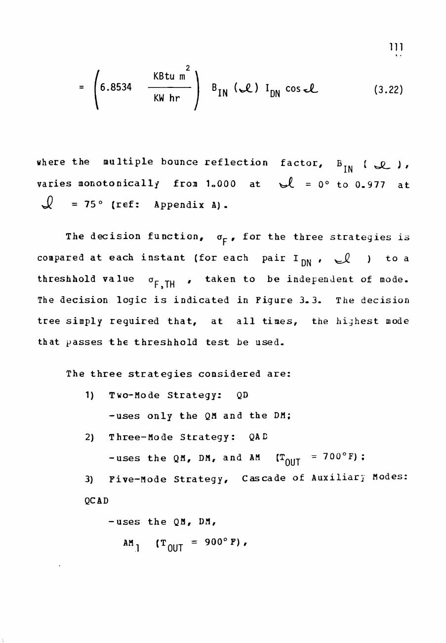
Ill
2 KBtu m
' • ' " ' l ^ r ^ \ ' IN(^) IDN"^^ (3-22)
where the multiple bounce reflection factor, B ( ^ j ^ ) ,
varies monotonically froa 1„000 at >Ji = 0° to 0.977 at
J? =75° (ref: Appendix A).
The decision function, Oj-, for the three strategies is
compared at each instant (for each pair I pj , _J2 ) to a
threshhold value a TU * taken to be independent of mode. r , IH
The decision logic i s indicated in Figure 3-3. The decision
tree simply required that, at a l l times, the highest mode
that passes the threshhold test be used.
The three strategies considered are:
1) Two-Mode S t r a t e g y : QD
- u s e s o n l y t h e QM a n d t h e DM;
2) T h r e e - M o d e S t r a t e g y : QAD
- u s e s t h e QM, DM, a n d AM (T^^^ = 700°F) ;
3) F i v e - M o d e S t r a t e g y , C a s c a d e of A u x i l i a r y Modes:
QCAD
- u s e s t h e QM, DM,
*«1 t OUT = ^ ° ° ° ^ ' '

112
r
v_
5£r :5oiJ\R,
BoiL£RS IN
ReS£r EPILBKS To JLOXJJE K
jies_
M£^ ruRU OFF jgcxiXjs so ToTfiL SOLfiK FLDO<Slcc»^ 1
FIND
PF
use £Q. 3. To
FIND </2r>
5: XHPor
Figure 3.3 Decision Tree for Q Strategies

113
AM (T^^^ = 800° F) , and
Each of t h e s e s t r a t e g i e s i s paramet r ized by tne s i n g l e
parameter o^ j ^ , t h e b o i l e r e f f i c i e n c y th reshho ld -
The goal of t h e fo l lowing a n a l y s i s was to f ind the bes t
switching p o i n t , o^ j ^ , i n order t o maximize and
prolong the b o i l e r l i f e t i m e . I t should be mentioned t h a t
the a n a l y s i s accoun t s fo r a n o t h e r swi tching funct ion appl ied
by CSPP t o i t s s o l a r g r i d i r o n b o i l e r s - As may be noted from
gaps in the Power Tab les of s e c t i o n 3 .2 .2 t he re a r e some
values of I_ | and \JL fo r which QM w i l l never be used.
This i s because t h e f l o w r a t e c a l l e d fo r by these p a r t i c u l a r
condi t ions i s benea th a minimum f lowra t e th reshhold- In
order to a s s u r e t h a t no i n l e t va lves t o the s o l a r b o i l e r can
ever ge t s t uck i n a p o s i t i o n which complete ly shu t s off flow
to the b o i l e r , t h e va lves a r e not allowed t o c l o s e
completely. T h e r e f o r e , t he re i s a minimum flow which can be
provided t o t h e b o i l e r s . I f any mode c a l l s for a f lowra te
below t h i s minimum f low, then the mode of ope ra t ion must be
changed to one which w i l l not c a l l for such a low flow. The
miniiDua f lowra te t o a 200 foo t g r i d i r o n was taken t o be 800

114
Ibm/hr in t h i s s t u d y - This number was based on exper ience
with t he ADVS-
3.3.1a The QD S t r a t e g y
In the QD s t r a t e g y t he s o l a r b o i l e r s are opera ted in
the QM (1000°F, 900 p s i a ) , u n l e s s t h e value of o^ r a i l s
below a p r e - s e t t h r e s h o l d v a l u e , a- ^^ - If Or- in the QM i s
below Qp j ^ then t h e s o l a r b o i l e r i s opera ted in
the DM (500°F, 900 p s i a ) . The amount of DM water i s
compared with the maximum amount of water which the f o s s i l
boi ler can u s e . T h i s maximum a l lowab le f lowra te to the
f o s s i l b o i l e r i s taken to be 59,000 Ibm/hr (CP 8 ) ,
corresponding roughly t o t he c h a r a c t e r i s t i c s of t u r b i n e 1
(ref: Subsect ion 3 . 2 . 1 ) - I f more flow i s produced than
could be used by t h e f o s s i l b o i l e r , then the s t r a t e g y shuts
down g r i d i r o n b o i l e r s , one a t a t i m e , u n t i l t h e r e i s no
excess water produced.
Based on t h i s o p e r a t i o n s t r a t e g y t h e annual ized average
of the power c a p t u r e d , 1 0<P >, by a l l t en Solar Bowls could
be found. F igure 3-U, shows the v a l u e s of <Pp > for QD
s t r a t e g i e s which have o^ j ^ from 0 t o 1. The peak in the

o o
o
115
.
o CXD
O
r>*
o t o
o un
o ^
o ro
O C\J
^ • ^
4-> fZ CU u S-cu Q .
c • 1 —
to cu
stra
tegi
Q
re fo
r Q
13 • M C^ ro
O
S-CU
s o O-
cu cn <a
Zi-P^O)
»«> L i_< :
t>
nnua
lize
d
< :
ure
3.4
CD
Ll_
o CO CVJ
CO m CVJ CJ) to m c\j
- M/n^aW < d> X 01

116
<P_>/ 26 ,225 K B t u / h r , which would a l s o r e s u l t i n t h e peak i n
a , o c c u r s when a p ^ ^ i s 0 . 5 . T h e r e f o r e , t he QD s t r a t e g y
which o p e r a t e s t h e s o l a r b o i l e r s i n the QM a s long a s a i s
50% o r g r e a t e r would p r o v i d e t h e b e s t s o l a r p e n e t r a t i o n . I f
the b o i l e r e f f i c i e n c y f a l l s below 50% then DM wate r i s
produced by t h e s o l a r b o i l e r s . F i g u r e 3 . 5 shows t h e a v e r a g e
value of Or f o r each QD s t r a t e g y .
3.3.1b The QAE S t r a t e g i e s
In t h e QAD s t r a t e g i e s t h e s o l a r b o i l e r s a r e o p e r a t e d i n
the QM u n t i l Or f a l l s below a d e s i g n a t e d Op y,, - When t h i s
occurs t h e b o i l e r s a t t e m p t t o o p e r a t e i n t he 700°F, 900 p s i a
AM. I f Or i s s t i l l below Op jLj,: t h e n t h e b o i l e r i s o p e r a t e d
in the DM- As b e f o r e , i f an e x c e s s of DM water i s produced
Solar G r i d i r o n s a r e s h u t down, one a t a t i m e u n t i l no e x c e s s
water i s s u p p l i e d .
The a n n u a l i z e d a v e r a g e power f o r QAD s t r a t e g i e s wi th
flp-j-^ r a n g i n g from 0 t o 1 i s shown i n F i g u r e 3 . 6 . The QAD
s t r a t e g y w i th Or- ju e q u a l t o 0 . 7 2 maximize t h e <Pp>, 28,020
KBtu/hr. F i g u r e 3 . 7 shows t h e a v e r a g e o^ fo r eacn CAD
s t r a t e g y .

117
o o
LO
o o
•S -.
C>J
to O)
CD (U
4-> ro i -
4-> CO
Q cy $-o
O
(U •r-CJ
• I — « f -< < -UJ
s -(U
o oo cu C7> ro S-cu >
<c (U N
ZJ c c
<:
un m
Qi i-Z3 CJ)
d CD
O o
o tn
LO CM
00 L ^<iD>

'^^/n^m Od> x oi

119 .-, o o
i n
" "
o o
t n
to cu
• r -CD CU
+-> ro i-+J t>0
czy
s_ o
^ -
>^ o c <u
•r— CJ
LU
CU
o CO
. tn C\J
cu CD ro J-cu >
•a: • a cu N
ro
C= C
cu S-Z3 CD
o o IT) o
i n i n CSJ
OOL X <^D>

120
3.3-lc The QCAD Strategies
In the QCAD strategies the solar boilers are operated
in the QM unless the value of a falls below a a . 1 1 the • F ,TH
boiler can not operate in the QM with a above the a_ _^ then r F, TrT
t h e b o i l e r i s o p e r a t e d i n an a u x i l i a r y mode which i s 100°F
below t h e QM t e m p e r a t u r e . I f Op i s s t i l l n o t a o o v e Op - rn then
an o p e r a t i n g p o i n t 100° F l o w e r i s t r i e d . The b o i l e r
o p e r a t i n g mode i s l o w e r e d i n t e m p e r a t u r e i n 100° f s t e p s i n
an a t t e m p t t o r a i s e o^ a b o v e ^cjit- I f t h e o p e r a t i n g p o i n t
r e a c h e s 700° F and o^ is s t i l l l o w e r t h a n o^ ju t h e n t h e
b o i l e r i s s w i t c h e d t o t h e DM.
The QCAD s t r a t e g i e s w e r e t e s t e d w i t h a r TU fi-'om 0 t o 1 . r , IH
The <Pp> v a l u e f o r t h e s e s t r a t e g i e s a r e shown i n F i g u r e 3 . 8 .
The peak v a l u e of <Pj .>, 2 7 , 6 2 0 K B t u / h r , o c c u r r e d when t h e
apTuWas 0 . 7 2 . The a v e r a g e o,- f o r t h e s e s t r a t e g i e s a r e r, In r
shown i n F i g u r e 3 . 9 -
hl'2 The D S t r a t e g i e s
The two D s t r a t e g i e s i n v e s t i g a t e d d i f f e r o n l y i n t h e
number of modes u s e d : a two-mode s t r a t e g y and a t h r e e mode
s t r a t e g y . i n e a c h c a s e t h e s t r a t e g y d e c i s i o n f u n c t i o n was

121 ro to
to Q.
O O CJ)
#\ u_ 0
o o cri II
1 —
to a .
o o cy>
9\
L L o O o 00 11 CM
to CL
O O CJ>
o o o II
CO
o o 1 °
o
o CO
o
o to
o un
•+-) c cu u i . cu
to cu
CD cu
+•> ta i-
-M <n Q cC CD
cy S-o
<+.
Qi i-Z3
+-> CL
ta CD
- cu
— O
o
o ro
O CM
Li_ CU b CD
ro S-cu >
<: •CJ cu N
ro zz c
00
cn
cu i -13 cn
O
CJ) t o CO
'4/n;aw <^d> OL

122
o <3
LO I —
CD CD
o x; LO
, L O CM
to CU
•I— CD CU
-(J ro
4-> C>0
Q < : c_> CJ
i-o
<+.
>) CJ c cu
•r—
u <+^
cu
o CQ
cu cn ro
cu >
<c • a cu N
ro Z3
c <c CD
OO
cu S-Z3 CD
o o LO CD
LO LO CM
OOL x < ^ D >

123
based on t h e irass flow r a t e , M, through the s o l a r b o i l e r s .
The value of M can be p r e d i c t e d for any I ^ ^ , Jl^ , and
T c o n d i t i o n s by us ing t h e TMRF formulas found i n
Appendix B. The same c o n d i t i o n s (Eg. 3.20) assumed for the
Q s t r a t e g i e s were a l s o used for the D s t r a t e g i e s . With
these c o n d i t i o n s t h e va lues of M may be obta ined from Tables
3 .2 -3 .5 . S e l e c t i n g t h e t a b l e a p p r o p r i a t e t o tne e x i t
temperature of t he mode the value of M i s
( tabular value of Pr) M = ^ (3-23)
Ah
where
Ah = t h e change in s p e c i f i c en tha lapy of f l u i d s througn
t h e s o l a r b o i l e r and can be found on each t a b l e .
In t h e D s t r a t e g i e s the va lue of M Deing produced Dy
a l l ten bowls i s compared with a maximum al lowable K va lue .
This maximum value i s based on the f u l l load tlow
requirement for t u r b i n e 1,
' MAX " 59,000 Ibm/hr . (3.24)

124
If too ffluch flow i s o c c u r r i n g then t h e bowls a re switched
one by one t o a mode with lower flow r a t e s u n t i l the t o t a l
ten bowl M i s below f ^ . i f a l l t e n bowls a r e in the QM
and too much water i s s t i l l be ing produced then the bowls
are shut off one by one. As long as only ten bowls a re
considered t h e p r o c e s s of s h u t i n g off bowls i s not r equ i r ed
by t h i s p l a n t -
The d e c i s i o n f u n c t i o n fo r D s t r a t e g i e s r e q u i r e s t h a t
the mode or modes producing the g r e a t e s t combined bowl f low,
Hj be used, but never exceeding M ny . The dec i s i on t r e e
for t he s t r a t e g i e s i s found in Figure 3 .10 . The two
s t r a t e g i e s c o n s i d e r e d a r e :
1.) Two mode S t r a t e g y : DQ
- u s e s only t h e DM and t he QM
2.) Three Mode S t r a t e g y : DAQ
- u s e s t h e DM, QM and AM3 (TQ^J = 700 °F) .
For t h e s e s t r a t e g i e s t he value of the s o l a r b o i l e r
e f f ic iency , o^ , was not the b a s i s for any d e c i s i o n s . Even
though Or i s impor tan t to b o i l e r l i f e t i m e , these s t r a t e g i e s
favored t h e mode o r modes with the h ighes t Op va lues
au toma t i ca l ly .
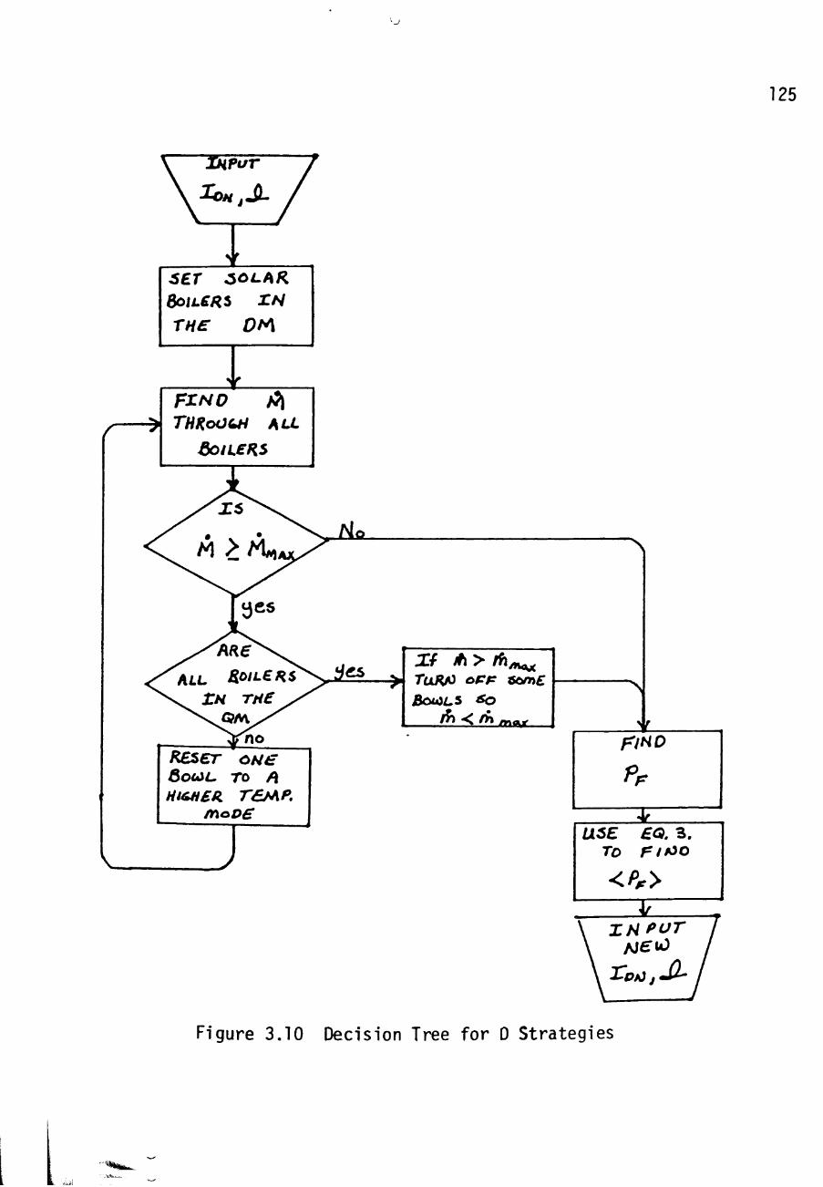
125
6ET ^OLAR BoiLCRi rN
rne DfA
I THRoOQH AU
eoiLeRs
REser SouiL, Ht&H£^
oNe ro /J r£MP.
/noDS
J
• >
PF
USE £0. 3 . To rif^o
<Pr>
Figure 3.10 Decision Tree for D Strategies

^J
126
3.3 .2a The DQ S t r a t e g y
In the DQ s t r a t e g y the s o l a r b o i l e r s are operated in the
DM as long a s M , t h e combined f l o w r a t e from a l l ten bowls ,
i s l e s s than M , t h e maximum f l o w r a t e regu ired by the
turbine (Eq. 3 - 2 4 ) - I f M e x c e e d s M„.^ for any I-.^. and
yJl^ c o n d i t i o n , t h e n one bowl a t a t ime i s swi tched to the
QH u n t i l M i s a g a i n l e s s than M .
The average annual f l u i d power captured x)y the DQ
strategy was fcund t o be
DQ <P > = 29,513 KBtu/hr.
The average b o i l e r e f f i c i e n c y was
DQ <ap> = 98.4%
It was a l s o found t h a t 48.1% of the <P p > "^^ from DM output
and the remaining 51.9% from the 1000°F QM o u t p u t . At no
time did any s o l a r b o i l e r s have t o be shut down due to an
excess of output f low.
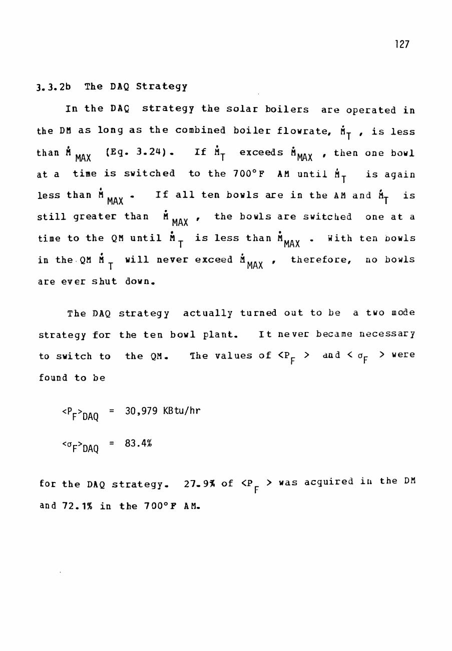
127
3.3.2b The DAQ S t r a t e g y
In t h e DAQ s t r a t e g y t h e s o l a r b o i l e r s a re opera ted in
the DM as long a s t h e combined b o i l e r f l owra t e , M , i s l e s s
than M ^ j . (Eq- 3 . 2 4 ) - I f M-j. exceeds Mj w , then one bowl
at a time i s swi tched to the 700° F AM u n t i l M-j- i s again
l e s s than M ,,.„ - I f a l l t en bowls are in the AM and M,- i s MAX I
s t i l l g r e a t e r than M ...^ , the bowls a r e switched one a t a MAX
time t o the QM u n t i l M^ i s l e s s than M,,.^ . With ten bowls T MAX
in t h e QM M^ w i l l n e v e r exceed M.,.„ , t h e r e f o r e , no bowls T MAX
are ever s h u t down-
The DAQ s t r a t e g y a c t u a l l y turned out to be a two mode
s t r a t egy for the t e n bowl p l a n t . I t never became necessary
to switch to the QM- The va lues of <P > and < Op > were
found t o be
<Pp>P^Q = 30,979 KBtu/hr
"^F^DAQ = ^^-"^^
for t he DAQ s t r a t e g y - 27-9% of <P > was acquired in the DM
and 72.1% in the 700°F AM-

128
3 . 3 - 2 C o m p a r i s o n of S t r a t e g i e s
B e f o r e t h e c o m p a r i s o n of t h e s t r a t e g i e s was made i t had
t o b e shown t h a t t h e c o m p a r i s o n was v a l i d even when
d i f f e r e n t B r i g h t Eye T a b l e s , BETs , w e r e u s e d . I n o t h e r
words , would t h e s t r a t e g i e s s t i l l c o m p a r e i n t h e same way i f
t h e I^., a n d ^j2_ c h a r a c t e r i s t i c s were s i g n i f i c a n t l y ON
d i f f e r e n t f rom t h o s e o f M a r c h , 1 9 8 0 - M a r c h , 1 9 8 1 . T h e r e f o r e ,
t h e s t r a t e g i e s w e r e a n a l y z e d u s i n g BETs w i t h s i g n i f i c a n t l y
d i f f e r e n t c h a r a c t e r i s t i c s t h a n s e e n i n t h e Annua l T a b l e
(Table 3 . 7 ) . T a b l e s 3 . 8 and 3 . 9 were u s e d . The r e s u l t s
i l l u s t r a t e d i n F i g u r e s 3 . 1 1 - 3 . 1 3 ^ o w t h a t t h e o v e r a l l
s c a l i n g o f t h e o p e r a t i o n a l r e s u l t s c h a n g e w i t h d i f f e r e n t
BETs b u t t h e r e l a t i o n s h i p s b e t w e e n s t r a t e g i e s s t a y b a s i c a l l y
t h e s ame .
The s o l a r p e n e t r a t i o n s f rom t h e s t r a t e g i e s a r e shown i n
Table 3 . 1 1 . T a b l e 3 - 1 2 s h o w s o t h e r i n t e r e s t i n g s t r a t e g y
c o m p a r i s o n s . The s i g n i f i c a n t r e s u l t i s t h a t t h e D
s t r a t e g i e s p r o v i d e t h e b e s t s o l a r p e n e t r a t i o n . I t i s a l s o
i m p o r t a n t t o r e c o g n i z e t h a t a p l a n t d e s i g n e d f o r a D
s t r a t e g y c a n be o p e r a t e d w i t h a Q s t r a t e g y w i t h t h e same
nodes . T h i s r e q u i r e s o n l y a s o f t w a r e c h a n g e i n t h e

129 o o
o CT»
O CO
o
.a ta
>> (J c ZJ cr <u
ro 13
c:
o (L)
r— CO -Q CT» »—
# 1
J-(U
^ E <U O (U
fO
(— >> o c cu r3 cr (U S-
o to
4-> E CU o
_ J -
LO Q .
(O (U
CD Qi
+-> <o S-
• M 0 0 C/)
<U Q 1 —
CO $- H-o
M- > , o
<U c s- cu
•!-> c r a. Qi to s-(_) u_
Q uu
1
C J - 4-> •r- <U C v _ . ^ CU
o s-- - CL. <V
o •".. oi,*^
0) sz > 4->
eC •!-
-o O M
CO • ! -
ro
cz c:
<x. CD CM • —
CO
CD
O CO CM CM
• — CO CM r—
i n CM cy» to ro
- M/n aW <^d> X OL
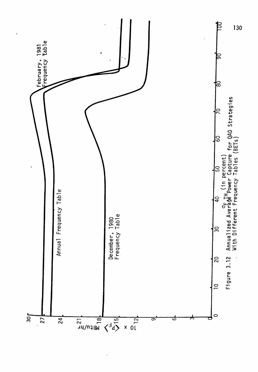
130
- o CO
. o r^
o t o
o i n
CD ";d-
o CO
o CM
to <U
•r— CD cu
+ J 03 J -+-> CO
Q <X. cy-^
tn J - H -O LU
M- DQ
^-^ 0) 4-> S- lO C 13 CU <U -M f— O CLJD S- ro ro CU <-) 1— C3.
J - >> C <U CJ
•r- 5 C «— O CU
CL 3 :r cr 1—CU CU
"Oi J -Li-fO U -
D i-cu •*-> > c
<c cu s.
-o cu Qi **-M t f -
•f— .f—
1 — Q ro 13 - C C •»-> C - f -
<C 3
CM •-; CO
(U J -ZJ CD
*JM/n: aw <'^d> X OL

m
*^4/n;aw <' d> X 01

132
to cu
•r— CJ) Qi 4-> ro $-
00
T3 C »o
o
c o
" I —
+-> ro s-
4-> CU c cu
s-fO
o 00
CO
cu
ro
c cu o s-cu
_4
cir < Q
CM
o II
Q ZC <C h-o cy u-
CM
• o II
Q za <C J—
Li_
G
O LO
• o II
c=r J—
D
umpt
ion
Tu
rbin
e
16.1
8
17.5
1
15
.42
16.6
8
14.4
3
15.6
1
14.6
4
15.8
4
13.6
9
14.8
2
i-H CM h- » -
-o ro O
22.1
1
24
.29
21.0
6
23
.14
19.7
1
21
.66
20
.00
21
.97
18.7
2
20.5
6
I-H CM h- 1 -
39
.55
42
.78
37
.68
40
.75
35.2
6
38.1
4
35.7
7
38.6
9
33
.48
36.2
1
1-4 CM 1 - 1 -
to to
<C
-a ta CJ
o
O <U
-a ro o
_ J
,— ( — 3
U -1
>^ ro
O
-o ro O
_ J
r— r— 3
U_ 1
4->
x : CD
•r— ^
1 —
3 U_
t o Z3 O r j
c •r— + J
c o
C J
-o ro
- O O ro - J O
f— rO
Z3 U.
1 >> ro
O
1 4-> - C CD
*r—
:^
-O "O ro ro O O
I s: > , CD ro •<-
CD -Z.

133
{/)
Qi
CD CU +-> fO $--M CO
M-O
c o to
• 1 —
S-rO Q . E O o
CM
• CO
cu Xi ta
h -
^^
cu c
.,— JD i-3
4->
ro O
_ J
r ^ ,— ^3
U_
to 13
nuo
•r—
o c_>
i ^ _ ^
"
C 1— O - r -
• r - O <U 4-> . Q 3 O ro -O +-> I- s-<U n3 c S-Q-f— 2 CU • O O O •!-> S-
to "O ro <U M- 2.— o Jz: +-> - r -
O 13 t/) o 4-> ro . C t O j a c: cu (o (u <U CJi— O lO to X - i -S- S- - I - CD to cu 3 to Q . O S- O O
- C <U 4->M-
: > •
Q
CO
s: (U <c -a t> o
s : • ^
JD
c o
• 1 —
4 J CM ro s : s- c i 4-> t ) (U c
O -
ro 1 — 1 ^
o ^ CO ca;
D
21 cy
t>
>-CD LU 1— c t cic: I—
r^ •
CM
CO
m m
"—
o o
• o
o o
• CD
o o
• o
t o CO
• CM
o l O
• o II Q re
cy h-
CO •
r^
o 1 —
. •—
o 1 —
. 1 —
^ ^
. r—
r>~ i n
• 1 —
CM
• 1 CT> 1
CM
• o
O II <C zn (ZJ
^ •
t o
i n o
• CM
^ 1 —
• t o
o o
• o
o o
• o
CO '= . \ t o
CM
• o
O II <: =n cy f—
#1
o o
CM «;i-
r^
o o
• o
CJ o
• o
<z> o
• CD
O o
• 1 0 0
cy o
o o
LO •
^^
r>. t o
. 1 —
1 —
c=> CJ
• o
o o
• CD
O O
• o
cy •a: o
1
oo

134
con t ro l l e r . If t he bes t s t r a t e g y , DAQ, in terms of so lar
penetrat ion i s chosen so the p lan t can a l s o operate with the
QAD s t r a t e g y .
Before leaving the d i scuss ion of s t r a t e g i e s i t should
be mentioned tha t one more highly s i g n i f i c a n t study was
made. This s tudy, however, analyzed the r e s u l t s of the CAQ
strategy when var ious number of so l a r bowls were used in the
plant. The r e s u l t s are given in Appendix D- This study was
made for the DAQ s t r a t e g y because i t was the s t r a t egy wnich
indicated the most favorable pene t ra t ion r e s u l t s .

CHAPTER IV
TACTICS FOB SOLAR BOILER CONTROL
The previous chapter demonstrated the importance of
control l ing the f l u id ex i t ing the so la r bo i l e r s in a ce r ta in
mode. The annual s o l a r pene t ra t ion of the plant depends
upon the s o l a r b o i l e r operat ion s t ra tegy and tne solar
condit ions. A s t r a t e g y i s chosen for operat ing the plant
based on how ituch s o l a r pene t ra t ion can be increased. Ihe
calculat ion of s o l a r pene t ra t ion for each s t ra tegy assumed
perfect c o n t r o l of the so l a r b o i l e r modes. That i s , if the
strategy c a l l s for a c e r t a i n output mode, tha t mode i s
produced i n s t a n t l y and s t ead i l y u n t i l the s t ra tegy c a l l s for
a mode change. Such per fec t con t ro l i s not r e a l i z ab l e in an
actual plant due to response t imes involved in the systera.
A control system i s required which wi l l bring the output
laode to the des i red mode as rapidly as possible without
damage to t h e b o i l e r . The b o i l e r can be damaged by large
overshoots in temperature or pressure .
135

136
In the proposed plant the fossil boiler controls the
output pressure of the solar boiler whenever superheated
steam is produced by the solar boiler- The ability to
regulate large pressure pulses from the solar boiler must be
incorporated in the pressure control system since large
pulses can occur due to abrupt insolation changes. This
control system utilizes a steam storage tank to buffer
against pressure variations and surges. Control of the
pressure i s an important concern in the plant and must be
studied in order to see if the fossil boiler control system
can respond appropriately to large pressure variations.
However, experience has shown that when the output mode
temperature is controlled in order to eliminate large
overshoots the overshoots in pressure are also greatly
reduced. In this study the control of the solar boiler
output temperature is investigated: adequate control of
pressure is assumed for this study.
The control system for solar boiler temperature
involves the positioning of a valve in order to regulate the
mass flow rate to the solar boiler. This Xind of control
can be obtained in numerous ways. Figure 4.1 gives examples
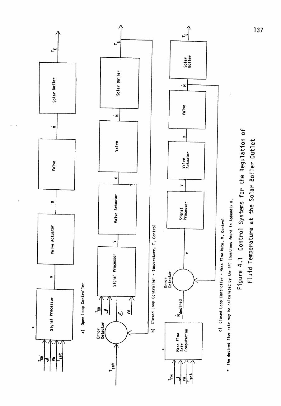
^
A 137
m r—
'o'o CO ca
1 .
o 00
01
> r— •o
1. o *J •0 3
•»J
u > • • £
<D
o
»
c
0)
o
o u o. o o
o. o
7r7K7r 4-> 01
« 4 -
o Qi
tro
l c o u
. X
» s n
£ U .
1
t .
ntr
ol
o (-> o. o o _ j
• D
O
, m X
"O c
a o. C
c 3
I t .
4/1 c o
3 o
UJ
L..
>s JO
• o Of
u *— u
w ^ >> '£
ta T—
3 cr> Qi cc Qi c~
-M
S-o
M-
to E CU
+J t/1 >>
CO
r—
o $-
-M C o
CJ
• ^ cu S-3 CJ1
• r -Ll_
ZJ o s-cu
^
o CO
s. ro — o
Ol - C • M
-M ro (U s-ZJ
• M ro J -<U Q . E Qi
•XJ •r -ZJ
r— L i -

138
of a few of the c o n t r o l schemes which a re f e a s i b l e . The
open loop con t ro l system in Figure 4.1a i s des i rab le but not
p r a c t i c a l . This i s because the valve and the plant do not
operate in exac t ly the same way a l l year : A manual valve
may be turned which wi l l change the plant response; the
valves themselves may erode and change c h a r a c t e r i s t i c s ; the
valve ac tua to r may change s l i g h t l y due to aging in the
e l ec t ron ic s . All of these lead t o the conclusion tha t a
system with feedback i s des i red . In t h i s study, both of tne
feeback c o n t r o l l e r s i n Figure 4.1 are analyzed. F i r s t ,
however, the exact system con t ro l philosophy and process
loop are reviewed.
i*-l Basic Control Philosophy
The b a s i c c o n t r o l philosophy of the process loop of the
solar b o i l e r s in the proposed plant i s the same as the
philosophy which has been applied to process control for the
ADVS boi le r - The process loop a t the ADVS i s i l l u s t r a t e d in
block diagram form in Figure 4 . 2 . The corresponding loop
for the proposed p lan t i s shown in Figure 4 .3 . The only
difference between the two, other than the number of solar
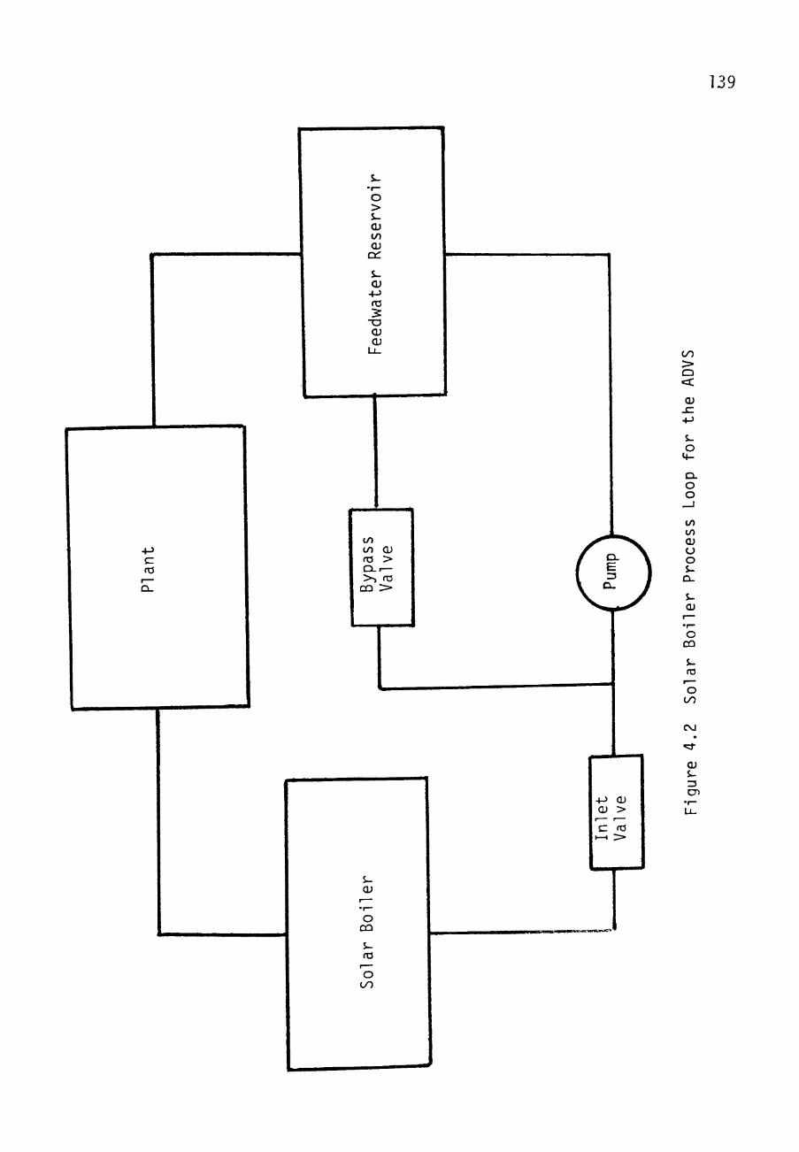
139
o > cu t o cu
ct:
i-cu
4-> ro
- a cu cu
c (O
to to cu fO > Q . I —
>, ro CQ >
W i
cu
o CQ
S-ro
O tyO
00 > Q <C
Qi SZ +-> S-
o
CL o o
to to cu CJ o s-
CL.
s-cu
o CQ
$-ro
O OO
CM
CU
s-CD
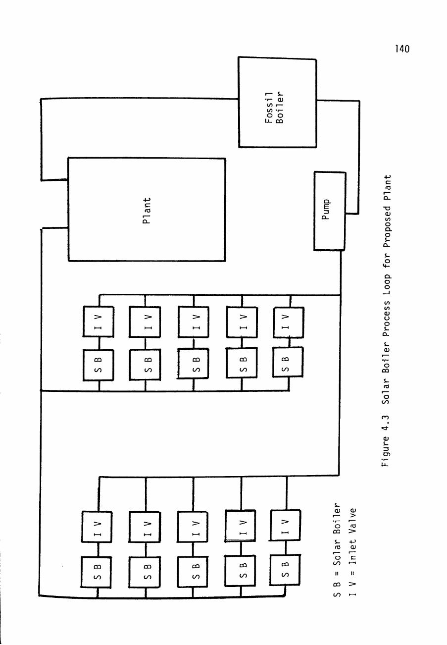
140
I — $ -• r - OJ ( / ) I — to • ! -O O
U_ CD
s-cu
r— • r-O
CQ
i-ro
r—
o tyO
II
CQ
OO
CU >
r— ta
>• 4 J CU
1 —
c t - H
II
>
» — 1
ro
CU to O CL O $ -
a. s-o
CL o o
to to cu o o S-
OL.
s-cu
o CQ
s_ ro
O OO
CO
cu s_ Z3
en

141
bo i l e r s , i s the absence of a bypass path in the la rge
system.
The bypass path i s necessary in the ADVS oecause a
constant speed pump i s u t i l i z e d . Since the pump pressur izes
the feedwater to a r e l a t i v e l y constant mass flow r a t e , and
since a constant mass flow r a t e i s not desired a t the
boi ler , pa r t cf the pressur ized feedwater i s sent back to
the r e s e r v o i r - The con t ro l of the amount of water bypassed
is accomplished by the i n l e t valve and the bypass valve.
The bypass valve i s regula ted by a s t a t i c pressure l i ne from
the i n l e t valve , so t h a t the two valves operate in tandem.
As the i n l e t valve i s adjusted, the bypass valve
automatically ad jus t s in an at tempt to hold the pressure
drop across the i n l e t valve cons tan t . The r e s u l t of the
tandem adjustment of va lves i s an almost l inear r e l a t i o n s h i p
between i n l e t valve pos i t i on and mass flow rate to the so lar
boiler.
In the la rge system there i s a bypass loop for the
solar bo i l e r s in t he form of the f o s s i l boi ler path. The
fossil bo i l e r has i t s own i n l e t valve which r egu la t e s i t s

142
mass flow r a t e . In a d d i t i o n , the pump speed can be varied
so t h a t , when l e s s flow i s needed due to lower generator
loads, the punps slow down. This e l imina tes any need for
bypassing water back t o the deaera tor r e se rvo i r .
In the proposed p lant each so l a r bo i l e r i s indiv idual ly
controlled with i t s own i n l e t valve and sensors . The mass
flow r a t e through t h e b o i l e r i s varied by manipulation of
the i n l e t va lve . The con t ro l system diagrammed in
Figure 4.4 shows the c o n t r o l system u t i l i z e d for each solar
boiler- Here a l l computational operat ions , tae error
detector and the s i g n a l processor shown in Figure 4 . 1 , are
incorporated into the s ing l e d i g i t a l computer of Figure 4 .4 .
This system diagram i s i d e n t i c a l to the one used for the
ADVS. Each block i n the diagram was modeled and the model
was compared with a c t u a l performance recorded a t the ACVS.
H'Z The Control System Model
In the con t ro l system shown i n Figure 4.4 the solar
boiler i s t h e component which i s the most d i f f i c u l t to
model. As nentioned in sec t ion 2 . 1 , the TMR equations
provide a good model for the s o l a r b o i l e r . This model was

143
a s. ^ Ol tz CL E
1 -
s - $ -ro CU r— r— O - 1 -co o
CQ
1
• s:
S-CU O 4-> cu > 4-> -O CU >
1— ro C r— e— ro 3 ro E fO
> 4-> I-H > O
<c
(U -o cr E ro ro +-> E r -E O O >
t J
^>
f— J-fO O 4-> 4-» •r- 3 CD Q-•-- E Q O
C_)
J 4J OJ t/;
H
^ A> 1
"ST. Q
t—1
<^
^
(U
o CQ
ro
O OO
ro
J-O
E CU •M to >-)
OO
o J -
+-> c o CJ
*
cu s -CD

144
used by Enayet J iwani i n a system model which wi l l be
referred to as the TMR System Model. This system model
included no time delay f a c t o r s ; t he re fo re , an improved
system model was made which included time delays and which
shall be r e fe r r ed to a s the TMRW System Model.
i - 2 . 1 The TMj System Model
Enayet Jiwani developed the Simulation Model shown in
Figure 4 . 5 . This model included the TMR equations to model
the bo i le r performance. These equations had been tested
against a c tua l ADVS performance and were superb for modeling
boiler performance, e spec i a l l y under condi t ions of steam
output from the b o i l e r . Jiwani made curve f i t s for the
performance record ings of the boi le r i n l e t valve for the
ADVS. The c o n t r o l a lgor i thms Jiwani used were i den t i ca l to
the ones used at the ADVS. These algori thms (discussed in
section 4.3) vary the voltage s ignal sent to pos i t ion the
valve, based on an e r ro r between actual and desired
temperatures a t the b o i l e r e x i t . Since the IMB eyuaticns
determine the f l u id power ex i t ing the rece iver , not the
fluid temperature, a curve f i t from steam tab les was made so
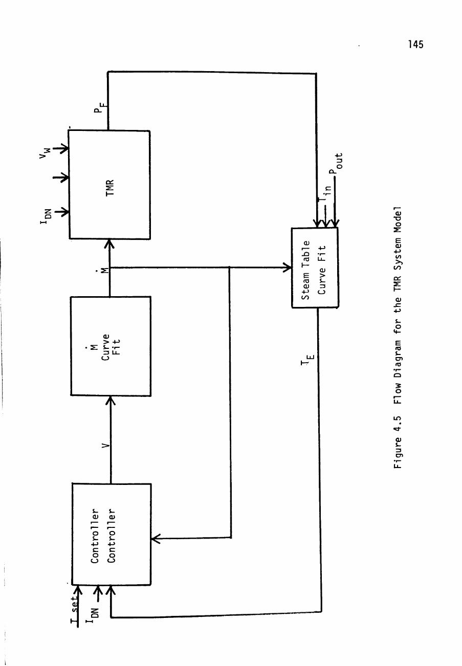
145
u. a.
1
- >
^
- >
TMR
>
• 2 :
V
(U > -M
. s : s- - 1 -Z3 U_
CJ
y
>
1
^
$- J -cu cu
r^ ^— r-~ r— 0 0 s- $-c c 0 0
0 0
A / ) . / a V 2 r
0
V
-M Z5 0
Ci-
h -
>-
^ < .
\fy/yf
Qi r— -M J 3 •«-ro U .
1— CU
E > ro S-CU Z3
•*-> 0 CO
LLJ
1—
(U •a o
cu to >>
00
CU .E +->
o
E ro $-CD ro
O
LO
Qi J-
CD

146
that temperatures could be found. With exception of the TMfi
equations a l l other system component models were formulated
from data collected at the ADVS. Examples of tne algorithms
used to simulate the valve performance are shown in
Appendix E. Appendix F l i s t s various curve f i ts for tne
steam tables- Jiwani used this model to see if i t could
simulate the control of the fluid state in the same way the
actual system controls the fluid.
4.2.1a Model Performance - Small Perturbations
The TMR System Model shown in Figure 4.5 was given the
same solar information measured as i t occured at the ADVS
system- The simulated temperature of the steam exiting the
boiler and the actual temperature recorded at the ADVS are
plotted in Figure 4-6 (EJ) - In addition to temperature the
simulated and actual voltage signals sent to the valve
actuator are shown in the figure- The simulated and actual
performance are in very close agreement, observation
indicating that the simulated temperature slightly leads the
actual temperature. This i s not an unexpected result since
there are no time delays in the model.
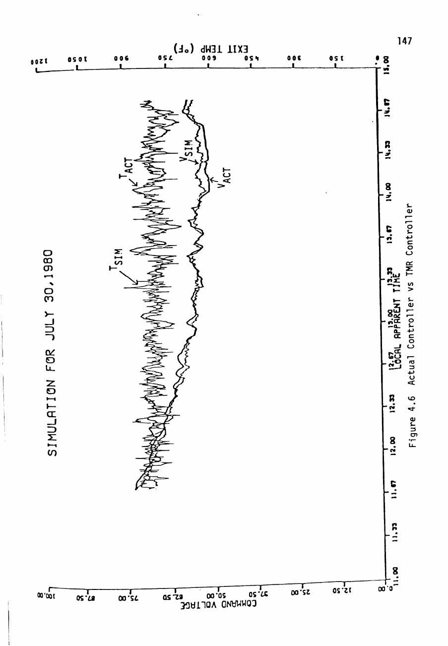
oozi OSOl _ _ l
0 0 6 I
(Jo) dW3i 11X3 0S£ 009 OS<i
_ ! I L_
147
OOC I
O S l _ l
O CO CD
O CO
O »—I
I— cr ID
I — «
in
OO'OOt I OO'Sd
T QSia 00'OS o s * «
30«iioA GNywwoo
T" OO'SJ
I OS'21
• 8
8
- n n
cu
o s-+J E o
CJ
to >
8( 3 I— 0 ^ I—
a. -M CC E
O _ i CJ
. - O ro
O <c
t o
cu s-Z3 CD 8 -
8
OO'O
148
a .2- lb Model Performance - Large P e r t u r b a t i o n s
F igures 4-7 - 4-10 show the performance of t he TMR
system model in comparison with a c t u a l system performance.
Large s t e p s i n mass flow r a t e , up and down, were forced on
the system while s o l a r i n s o l a t i o n remained s t eady in
Figures 4 .7 and 4 - 8 . In F i g u r e s 4-9 and 4.10 l a r g e s t eps
in d i r e c t normal i n s o l a t i o n were s imula ted by t ak ing the
solar b o i l e r out of t h e f o c a l r eg ion and by p lac ing i t back
into the f o c a l r e g i o n . Even though t h e a c t u a l performance
and s imula ted performance converge a f t e r some t ime, the re
are l a r g e d i s c r e p a n c i e s in the two, p e r s i s t i n g from one to
almost four n i n u t e s . Such d i s c r e p a n c i e s were the major
reason for making an improved model.
i-2-2 The TMRJ System Model
The TMR Model g i v e s a c c u r a t e s teady s t a t e and small
per turbat ion s i m u l a t i o n s , but improvement during l a rge
t r a n s i e n t s was needed . There fore , the TMRW System Model
shown in F igu re 4.11 has been developed- Each block t h a t
d i f fers between t h e two models r e p r e s e n t s a time d e l a y . The
computational time de lay i n c l u d e s t h e process ing time for a

149
o o V A(
SZ . E
JD JJ
in o «* o CO t o
II
CM
to o
o II
cu 4-) to
t/J
ro
CJ
<C
o CTv
/
CU +-> to >) oo oz
LO
/ /
/
/ /
/ /
/ /
/
o to
(J cu (/)
LO
CU
E
/ o CO
"DrtDT "Ufe 005 (Jo) aun:^pjaduja:; :;LX3
LO
092
cu +-> to >)
00
QZ
to >
E Qi 4-> to >>
OO
t—
ta 13
•4-> O
< :
r>v.
• ^
cu s-
E •t—
CL ZD
a. Qi
• M tn
Qi CD i . ro
_ J
CD

150
E CU -P to > i to •:: 2:
\
/
cu +J to
CO
ro
<C
0 0 V Al
+-> -M
- E JC
"E^^E JD JD 1 — I —
LO CJ CM «::J-t o CO
CM
E 3 : :i^
-
cn 0
II
o CM
\
\
o CO
CJ LO
CJ CM
to 13 0
• r ^
> CU S-a. 0
-M
cu zs
-a cu s-13
•4->
ro S-cu Q-E cu
+ J
JZZ CD
• 1 —
S-cu
r— • 1 —
0 j Q
CU JZ + J
14-0
to CD E
• 1 —
-M fO CU
E (U
+-> to >>
00 ct:
0 cr>
,—^ <j Qi to
cu E
•r— 1—
to >
E CU +-> to >^
oo 1—
ta Z3
+J 0 <c
E •r—
E S 0
Q
CU +-> 00
CU CD
ro
o to
CO
cu J-Z3 CD
CJ CO
000 L 05Z 00s 05Z

151
o o
o o V Al
+-> +-S
CM CM
to o o Cr> CJ
o o II
o CO
f E cu
+J to
>J lO
Qi
LO
/
zr II
cu +-> to >) to
ro
a
cu 4-> to
OO
CJ LO
o cu to
cu
LO CM
to >
E CU
4-> to >^
OO
r—
ro 3
4-> O
<:
CD
^
CU s-
E •r—
E S O
Q
Q . a;
4-> tyO
cu CD S-ro
_ J
CD
000 L 1 1
05Z 009 ,093 (Jo) a^nq.Bv4aduja:; :^LX3

152 o
- I 0 0 CM
\
CO >-oo
\
\
o o
4-> 4 J
CM CM
O r— O CT>
• • o o
o CM
\
o CO
II
o o CM
CO >-CO
a: s: 1-
o to
\
\
CJ cu to
\
\
cu s-:J
4-> ro S-
cu
>+-O
CD E
• 1 —
+-) ro CU
C L J E E CU
4->
1 —
ro • f —
+-> •r— E
•r—
- E CD
• 1 —
- E
to 13 O
• I —
> CU S-Q .
O
+-) OJ Z3
T 3
S_ CU
,— • 1 —
o JD
s-03
r—
o to
CU JZ
+->
o CM
E CU
+-> to >>
m or 21 h-
to >
E CU
+-> to
>> oo r—
ro 13
+-> O
<c
•Zi Q
1—1
E •r—
Q . rD
Q . CU
+ J OO
CU CD s-ro
CJ 0 0
CU S-ZJ CD
o
000 L 09Z 009 092 ( 3 o ) 9^n:^pj9duj9:^ :;].X3
0

153
ct:
cu
oiz. ca , . ^ . ^ _ _ _ _
1 ' ^ I "^ ''"i cu
CU
> 13
QJ
ro
CU X 5
S-
<v
CD i -+-> E O
C_)
LU
4 ^ ^ Qi to
CU
o
cu -M to
t /1
I—
cu . E 4->
o
fO i_ CD ro
•r— Q
cu S-Z5 cr.

154
d i g i t a l computer t o analyze a sensor s i g n a l and c a l c u l a t e a
new actuator s i g n a l . In most c a s e s , t h i s delay depends on
the computer used and the cyc le time reguested. For the
ADVS the delay t ime i s 0-8 seconds. For the proposed plant
the delay should a l s o be in the 1 second range.
The valve delay block inc ludes severa l delays . The
transmission time for the ac tua to r s i g n a l to reach the
actuator may be represen ted here ; however, t h i s i s a
negligible time for both the ADVS and the proposed plant .
The actuator response time i s included in th i s block. The
fflain idea i s to model a smooth, ra ther than ins tan taneous ,
change in valve p o s i t i o n . This smoothing was accomplished
by using an a lgor i thm such as :
Vy tt) = ^A^^"^^ * G^(V(t)- V;^(t-1)) (4.1)
where
VA = ac tua l vo l tage for pos i t ioning the valve
V = vol tage t ransmi t ted by the process con t ro l l e r
t = time in seconds
G = a cons tan t which r e g u l a t e s response time.
Based on ADVS ac tua to r performance, G was se lec ted to ue

155
G, = 0 .33 3-A
This causes a valve performance such as shown in Figure 4.12
when the t r a n s m i t t e d vo l t age to the a c t u a t o r changes by
100%-
The two remaining t ime de lay b locks s imula te response
times of the s o l a r b o i l e r . The models £ u i l t for these
blocks are e m p i r i c a l and a t t empt only t o s imula te measured
performance. While some -physical e x p l a n a t i o n s for the
delays helped t o i n i t i a t e the models, i n depth q u a n t i t a t i v e
understanding of t h e t r a n s i e n t behavior of the u o i l e r has
not been s t u d i e d .
The b lock l a b e l e d "water l i n e de lay" models t h e lack of
any b o i l e r response t o i n s o l a t i o n or flow caanges for a
f i n i t e t ime, a deadband. In p a r t , t h i s delay time can be
a t t r i bu t ed t o a d i f f e r e n t mass flow r a t e occuring at the
in le t and t h e e x i t ends of the b o i l e r . This i s due to the
vast d i f f e r e n c e i n v e l o c i t i e s of s t eaa and water in tae
tubes and t h e c o m p r e s s i b i l i t y of steam. To approximate tue
delay, c rude assumpt ions were made to s impl i fy a c t u a l f lu id
performance.

00 156
to
LO
a cu to
cu E
CO
CU
u E ro E S-
o 4 -X-cu
QL.
cu > ro
CU
ro
CU Q
CM
CU S-Z3 CD
CM
OOL H 1 9Z 09
(%) pupuiuoo aALPA 9Z

157
The f l u i d i n t h e b o i l e r was assumed t o be water a t the
i n l e t t e m p e r a t u r e or s t e a m . T h e r e f o r e , t h e r e i s a water
l i n e r a t h e r t h a n a two p h a s e r e g i o n i n t h e D o i l e r . T h i s
l i n e moves a t a v e l o c i t y based on the i n l e t t e m p e r a t u r e and
the b o i l e r t u b e d i a m e t e r a s w e l l a s t h e mass flow r a t e of
f e e d w a t e r . T h i s v e l o c i t y can be app rox ima ted by
v e l =JP A/(3600*M.,) (4.2) it
where
jf = w a t e r d e n s i t y a t t h e i n l e t t e m p e r a t u r e
( Ibm/ f t )
A = c r o s s s e c t i o n a l a r e a of b o i l e r t u b e s ( f t )
and
M = mass flow r a t e p e r b o i l e r tube ( I b m / h r ) , t
3600 c o n v e r t s h o u r s t o s econds .
The p o s i t i o n of t h e wa te r l i n e depends on t h e s o l a r
i n s o l a t i o n , t h e c o n c e n t r a t i o n p r o f i l e on the b o i l e r , and the
mass flow r a t e . The c o n c e n t r a t i o n p r o f i l e for a o o i i e r a t
^ = 0° i s shown i n F i g u r e 2 . 3 . T h i s p r o f i l e was used for
modeling p u r p o s e . The p r o f i l e a t o t h e r i n c l i n a t i o n a n g l e s

158
differ from this one as can be seen by the profile for
Ji =30° shown in Figure 4.13. To account for these
differences the model assumes a symmetrically illuminated
boiler { v*^ =C°), but an insolation of:
I^^ cos V^ , (4.3)
A piecewise linear approximation of the profile in
Figure 2-3 was made and is shown in Figure 4-14. with this
approximated profile and an insolation and inclination
reading the solar energy along the boiler tubes can be
simulated- Based on another assumption—that 80% of the
energy reaching the boiler wall i s absorbed and transmitted
to the liquid water in the boiler—the location of the
boilinq line for the model can be calculated. This i s done
by finding the enthalpic energy required by the fluid to
bring i t from the inlet temperature to lOO/i steam at the
saturation temperature. For water at 219° F and 900 psia the
enthalpy i s approximately 188 Btu/lbm (ST). For 100% steam
at the saturation temperature with 900 psia the enthalpy is
1195 Btu/lbm (£T). Therefore, the fluid must gain:

159
o O CO II
i o
M -
S-cu >
cu o cu oz • o Qi E CD
E ro
E O
>, i-o +-> to
ro O
+-> CL
o
CO t—I
•
cu
Z3 CD
00/,

160
cu
*+-o E O
•r— +J ro E
•r—
X o S-Q. a.
<c S-ro CU E
•r— _ J
<u to
• r -
^ CU o cu
• 1 —
D.
^ r-H
CU s-Zi CD r—
J -
c^l i >' s-o
^-S-cu >
•F—
cu o Qi
Ol
T3 Q) E CD
• r -r— <C E ro E O
CU r— 1—
M-O J-
O^
,— ro O
•r—
• M Q. o

161
OUT " ^IN " 1195 - 188 = 1007 B t u / l b m . (u.14)
The t o t a l power r e q u i r e d t o b o i l t he i n l e t water would be
M (1007 Btu / lbm) j4_ 5j
where M i s f e e d w a t e r mass flow r a t e p e r b o i l e r t u b e i n
pounds pe r h o u r . The s o l a r power t r a n s m i t t e d to t h e f l u i d
can be found ty
* DN ^""^ iJi ) 9^^^ " ^^ t'*-^)
where
"^ = the assumed efficiency for the water end of
the boiler ( = 0.8)
Ipjl = direct normal insolation (Btu/hr-ft /sun)
>JL = solar inclination angle (degrees)
^(L) = profile along the receiver (suns)
V = width of sclar boiler tubes
L = distance from solar boiler tube inlet to
the water line.

162
The distance is found from the boiler inlet to the place
where sufficient energy has been transmitted to the fluid in
order to boi l . This i s done by integrating Equation 4.6
from 0 to L, where L ranges from 0 to 430 f t . , until the
power found from Equation 4.6 equals the power found in
Equation 4.5, or L = 430, whichever is smaller. The water
line is positioned at the distance d from the boiler inlet .
This whole procedure leads to the modeling of a water
line position based on I , \Jl. , and M. Any changes in
l^.,, ^ , and M a l te rs d- In the water line delay model,
d can only move at the velocity of the feedwater found in
Equation 4.2- The solar boiler model, TMR Equations, sees
no change in I^ or M until the water line is allowed enough
time to reach i t s proper position.
This computation results in a deaduand which
approximates the observed system deadband. It must be noted
again that th i s water line delay is not believed to be the
only cause of the deadband. Many other factors are involved
such as the conduction time of energy through the boiler
wail. Even though the delay factor was simulated r y

163
e q u a t i o n s from a c t u a l c o n d i t i o n s which can occur i n t he
b o i l e r t h e r e s u l t i n g d e l a y e q u a t i o n s s h o u l d be c o n s i d e r e d
only a s m a t h e m a t i c a l e q u a t i o n s model ing an observed
per fo rmance , and n o t a s e x p l a n a t i o n s f o r t h e pe r fo rmance .
The f i n a l d e l a y b l o c k i n t h e TMRW model a c c o u n t s fo r
the f a c t t h a t t h e b o i l e r w a l l h a s a c e r t a i n c a p a c i t a n c e for
s o l a r e n e r g y . Also^ t ime i s i n v o l v e d b e f o r e energy can be
t r a n s m i t t e d from t h e b o i l e r i n n e r w a l l t o t h e f l u i d . Th i s
a c t i v i t y i s a very d i f f i c u l t b e h a v i o r t o model. The o lock
l a b e l e d t e m p e r a t u r e d e l a y r e c e i v e s a s i n p u t s t n e TMR based
c a l c u l a t i o n s of power i n t h e f l u i d , P , t h e mass flow r a t e
of the b o i l e r f l u i d , M, t h e i n l e t t e m p e r a t u r e of t h e f l u i d
to the b o i l e r , T , t h e p r e s s u r e of t h e f l u i d e x i t i n g the IN
b o i l e r , P , and t h e t e m p e r a t u r e of f l u i d e x i t i n g the OUT
b o i l e r one second a g o , T ( t - 1 ) . The s p e c i f i c e n t h a l p y of
the f l u i d e n t e r i n g t h e b o i l e r , h^^., and e x i t i n g the b o i l e r , IN
h , i s c a l c u l a t e d
" I N = ^ I N - 32 '^-^»
^ OUTC = ^ P / " * '' IN ( 4 . 8 )

164
However, the assumption i s made tha t the enthalpy of the
exi t ing f lu id goes through smooth, not discontinuous, changes.
Thus the a c t u a l enthalpy of the ex i t ing f lu id n^..^ i s found
by
^OUT^^^ = ^OUT^^-^^ * ^/^^ ^^OUTC~ SUT^^-^^J ^''"^
where
t = time in seconds
R = v a r i a b l e based on mass flow r a t e
C = va r i ab l e based on previous exi t temperature
The value of C i s found by
T ^ ( t - I ) < TgQjL
0 .6 T £ ( t - 1 ) > TgoiL
(4 .10 )

165
where T . i s found by
^ A C T = ^ ' ' ' ' ' ^OUT ^ ' ' ' ' '
"^BOIL = ^Q"^ - lO^IPpACT ) - 37(PpACT f - (4 .11)
The v a l u e of R i s f o u n d by
R = 15 ^ 2 5 0 e-f'^/SOO) (4 .12)
These va lues were determined from da t a c o l l e c t e d a t tae
ADVS. Appendix G shows the computer l i s t i n g for t he TMRW
model.
4.2.2a Model Performance - Small P e r t u r b a t i o n s
The THR» Model of F igure 4 .11 was used with a c t u a l data
co l lec ted a t the ADVS to s i m u l a t e p r o c e s s loop behavior .
This s i m u l a t i o n i s compared to a c t u a l ADVS performance in
Figure 4 . 1 5 . The F i g u r e shows t h a t the system performance
was a c c u r a t e l y modeled by the model- The TMRW Model shows
smoother t e m p e r a t u r e r e l a t i o n s t h a t a r e more nea r ly in phase
with t h e a c t u a l da ta than the TMB Models r e s u l t s
(Figure 4-6) .

8 - 166
O OO CD
8
o cn
o LL.
o » — « J — cr _ j ID •—I
CO
E • 1 —
to J— II cu > s_ ZJ u
.^ J -ro
CJ
+-> o ro
1— II CU > J -Z3 o +-> .cz CD
•r—
_ J 2 ;
cu
o
+-> E o o
CcT
Q t J
-r icr —a.
a. cr _ j
C o -' 3
"~~^
R •
to
> S.-
<v '— 1 —
o -t-J
E o <_) ,— fO 13
-M U
c t
LO
""
-i cu 13 CT'
(Jo) ciW31 11X3 OS H "~r~"
O O C
^ — o ; (
S
3

167
4.2.2b Model Performance - Large Perturbations
The TMRW model was used to simulate system performance
when faced with large changes in insolation or mass flow
rate. Comparisons of simulated performance to actual
performance are seen in Figures 4.16 - 4.19. While tne
simulation i s far from perfect i t i s superior to the
simulations obtained from the TMR System model faced with
large perturbations. In particular the TMRW System Model
can simulate some of the problems faced in response times
during large transients. If these response times are
ignored, a simulated control system can look much better
than the actual control system. That is , when the
computational operations, or controller, i s developed witn
no time delays, the actual use of this controller might be
totally unacceptable. However, when time delays are
considered, a more useful controller may oe found-
ii-3 The Controllers
The reason for developing a system model is to try to
find ways to improve the system response. The easiest way
to improve the system in Figure 4.11 is to find the best

168
o o V A|
+->+-) CM
O cn
LO
o to
cu +-> to
>, oo Cr:
LO
to > E CU
-M to >>
OO
1 — fO Z2
-M CJ
CC
E • i—
CL r j
CL. CD
-M OO
cu CD S-fO
CD CO
t o
CU S-13 CD
vtmr -0^ Qite 09T ( d o ) 9'>in:;ej9diii9:; : ; L X 3
LO

169
cu to >^ t/0
s o: ^. \ — •
to >
E cu +-> to >^ t/O
1 —
fO =3
-«->
o «3:
E ••-
E ^ O Q
D. cu +-> tyO
CD <J^ i-ra
OJ
Z3
cr>
000 L 009 092 (Jo) s^nr Buadujaq. :;LX3

170
o o V A
CM CM
to o CT»
c-> 1
CJ o o
» v ^
E J 3 I —
o <d-co
to >>> to
3 D i ^' h /
E CU
+-> to >
00
on
to >
E CU
-M to >
tyO
1 —
ro 13 +-> U
< :
E • /—
E S O
Q
E cu
4-> t/O
cu c S-fO
0 0
cu
005 D9T (Jo) 9^n:^pjadui3:; :;LX3
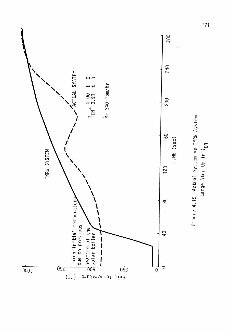
171
CJ 0 0 CM
O
CM
O CZ> CM
CJ to (J
CU to
cu +-> to
oo
CC
CJ CM
13 \ +J \ ro \ S - ^ CU CL
E cu
+-> to Z3
I— o ro -r-
•r- > +-> CU • 1 - s^ E CL
• I —
o sz 4-> CD
• I - CU JZ Z3
-a
<v ^ sz -(-> S-
cu <+- t— O - 1 -
o CDXJ E
•r- i_ +J n3 ro 1— CU O
- E to
to > E CU +-> to >,
cn t—
<a Z5
+-> o <c
1—1
E • f—
n. r j
Q -CU
-!-> OO
CU CD S-ro
o 00
CD
QJ
000 L ite D(te^ 092 ( j o ) ajn:;ej8duj9:; q.LX3
CD
0

172
algorithms i n the process computer. The a lgor i thms are
referred to as t he c o n t r o l l e r and two t a c t i c s for con t ro l
were i n v e s t i g a t e d . The f i r s t t a c t i c u t i l i z e s a c o n t r o l l e r
which opera te s on an e r r o r in the measured (or simulated)
solar bo i l e r output temperature and the des i red , or s e t
point, tempera ture . A c o n t r o l l e r of t h i s type i s p re sen t ly
in use a t t he ADVS- The second t a c t i c for c o n t r o l l e r s i s to
operate on an e r ro r between the measured (or simulated) mass
flow r a t e and the mass flow r a t e ca lcu la ted by the RFC
equations (Appendix B) required for a ce r t a in temperature
output from the s o l a r b o i l e r s . These two t a c t i c s are
discussed below.
i - i - 1 The T Ccn t ro i l e r
The T C o n t r o l l e r i s i l l u s t r a t e d in Figure 4 .20. This
control ler i s c u r r e n t l y being u t i l i z e d a t the ADVS. This
par t icular s e t of a lgor i thms was developed by Dr. John D.
Reichert and i t s development i s explained in J i w a n i ' s work
(EJ) . The e r ro r in the valve actuator s igna l i s determined
by

173
vJ I I
A v
CU
o 4-> E O
CJ
(U
o CM
(U
CD

174
where
I ., = direct noriral insolation DN
<I Pl>.> = a sliding average of I
T = neasured temperature at the boiler output
T,. = desired temperature at the boiler output,
A sliding average of a term simply means that current inputs
are weighted more heavily than previous inputs when
averaging the value. This type of averaging can be done by
an algorithm such as
<x>{t) = <x>(t-1) •G (x(t) - <x>(t-1)) (4.14)
or
t
<x>{t) = f G [x(t) - <x>(t-1)J dt / G [x(t)
J ^ to
The factor G„ determines how heavily the most resent data is
weighted. The larger G. ,the more heavily current data is
weighed so the value of <x> would approach the current value
of X more quickly. The sliding average of I is found by:
DN
< ^ D N " ^ " ^ = < ^ D N " ^ ^ - ^ ^ " ^i^^DN^^^ - ^ ^ m ^ ^ ' - ' ^ ^ ' ^'-''^
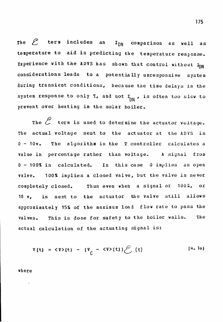
175
The ^ t e r n i n c l u d e s an l^^ comparison as wel l a s
temperature t o a i d i n p r e d i c t i n g the t empe ra tu r e r e s p o n s e .
Experience wi th t h e ADVS h a s shown t h a t c o n t r o l without IQM
c o n s i d e r a t i o n s l e a d s t o a p o t e n t i a l l y unresponsive system
during t r a n s i e n t c o n d i t i o n s , because the t ime de lays in the
system re sponse t o on ly T, and not I , i s of ten too slew t o
prevent over hea t ing i n the s o l a r b o i l e r -
The o term i s used to determine t h e a c t u a t o r v o l t a g e .
The a c t u a l v o l t a g e s e a t to t he a c t u a t o r a t the ADVS i s
0 - lOv. The a l g o r i t h m in t he T c o n t r o l l e r c a l c u l a t e s a
value i n p e r c e n t a g e r a t h e r than v o l t a g e . A s i g n a l from
0 - 100% in c a l c u l a t e d . In t h i s case 0 impl ies an open
valve. 100% i m p l i e s a c losed v a l v e , but the valve i s never
completely c l o s e d - Thus even when a s i g n a l of 100^, or
10 V, i s s e n t t o t h e a c t u a t o r the valve s t i l l a l lows
approximately 15% of t h e maximum load flow r a t e to pass the
valves- This i s done fo r s a f e t y to t h e b o i l e r w a l l s . The
actual c a l c u l a t i o n of t he a c t u a t i n g s i g n a l i s :
V(t) = <V>{t) - (V - < V > ( t ) ) ^ (t) t4. 1o)
where

176
V (t) = ac tuat ing s i g n a l in %
<V>(t) = a s l i d i n g average of V
V = a cons tant .
The s l i d i n g average for V i s found by
< V > ( t ) = < V > ( t - 1 ) + G^ ( V ( t ) - < V > ( t - 1 ) ) . (4 -17 )
The values of V and <V> are always clipped so that they are
never greater than 100 or less than 0. If one of the limits
-0 or 100- is calculated for V the value of G is increased. V
This will bring the value of <V> closer to V.
The value of V^ in the equation must always be greater
than the value of <V>(t) if the proper command - more open
or more closed - called for by the cL^ term is to be sent to
the valve. In practice Vp is usually kept greater than 100
to assure this. The T controller, listed in Appendix G, was
used in conjunction with the rest of the TMRW System Model
for the large system in order to find the best values of G^,
G , and V to be used in the contrcller.

177
Tes t ing the T c o n t r o l l e r involved s imula t ing va r i ous
DN c o n d i t i o n s . The c o n t r o l l e r was t e s t e d while i t had a Tr
of 1000°F. This was done because overshoots i n t h i s range
must be l i m i t e d f o r t he sake of the b o i l e r . A maximum
overshoot of 1260°F i s a l lowed. Various va lues of G - GT^ V 1
and Vp were t e s t e d and the I n t e r g r a l of Time m u l t i p l i e d by
the Square of the E r r o r index , ITSE, was c a l c u l a t e d . Ihe
ITSE index p r o v i d e s a s i n g l e c a l c u l a t i o n r e l a t i n g
overshoots , u n d e r s h o o t s , and s e t t l i n g t i m e . In reducing the
ITSE index t h e s e t h r e e system responses are a l l cons idered
and usua l ly reduced- The ITSE i s found by
ITSE = / t E dt (4. 18)
where
E = 1 - T^ . (^.1^)
Table 4-1 shows t h e v a l u e s of G^, G^, and V^ which are
favorable f o r e i g h t d i f f e r e n t i n s o l a t i o n v a r i a t i o n s .
Figure 4-2 1 - 4.28 show the p r e d i c t e d temperature response

Table 4.1
Favorable Parameters for the T Controller
178
' J ^ 0.01 t 10
^ 1.0 t 10 T^= 1000
^ , _ 1.0 t 10 DN ' 0.01 t 10
T^= 1000 3
Ipf^=t/1200
T^= 1000
4 Ipf^=l-t/1200
T^= 1000
^ t Ip^=.9+.lsin(^)
1^=1000
6 t Ip^=.6+-4sin(^)
T =1000
7 t Iorj=.9+.lsin(gQ)
T^=1000
^ t Io^=.6+.4sin(gQ)
T^=1000
J 1000 t 10
^ 500 t 10
' I = 0 9 ^DN ^'^
J ^ 500 t 10 s 1000 t 10
^c
250
250
250
250
250
250
250
250
250
250
^I
0.4
0.4
0-4
0.4
0.4
0.4
0.4
0.4
0.4
0.4
S
0.015
0.015
0.05
0.05
0.05
0.015
0.05
0.05
0.05
0.05
ITSE
0-4 E9
385.4E9
40. E9
1.33 E9
60.7 E9
0.6 E9
2.0 E9
9.8 E9
0.34 E9
0-05 E9
^MAX
1000
1000
1239
1260
1113
1039
1241
1147
1069
1000
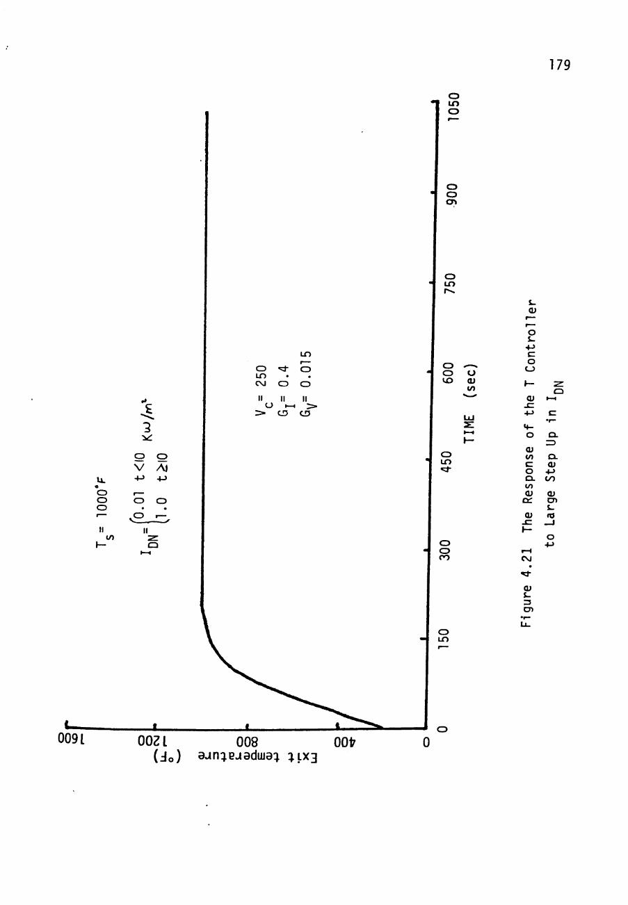
179
o i n o
o o CTt
« o o o
to
2
o o V AJ
4-> 4->
O O
• • II •z.
CJ
o LO
250
II
0.4
II
to
0.0
1
II o
CD CD t o
O CU to
cu
o s-+-> E o
CJ
CO CD
Q Qi K-1
SI +J E
O t n
cu to E o a. to cu az Qi
Q . cu
• M I/O
O) CD s-ro
o CD CO
009 L
CM
Qi S-3 CD
o LO
o 002 L 008 0017
(Jo) - n: eJ^dllJ : :^LX3 0
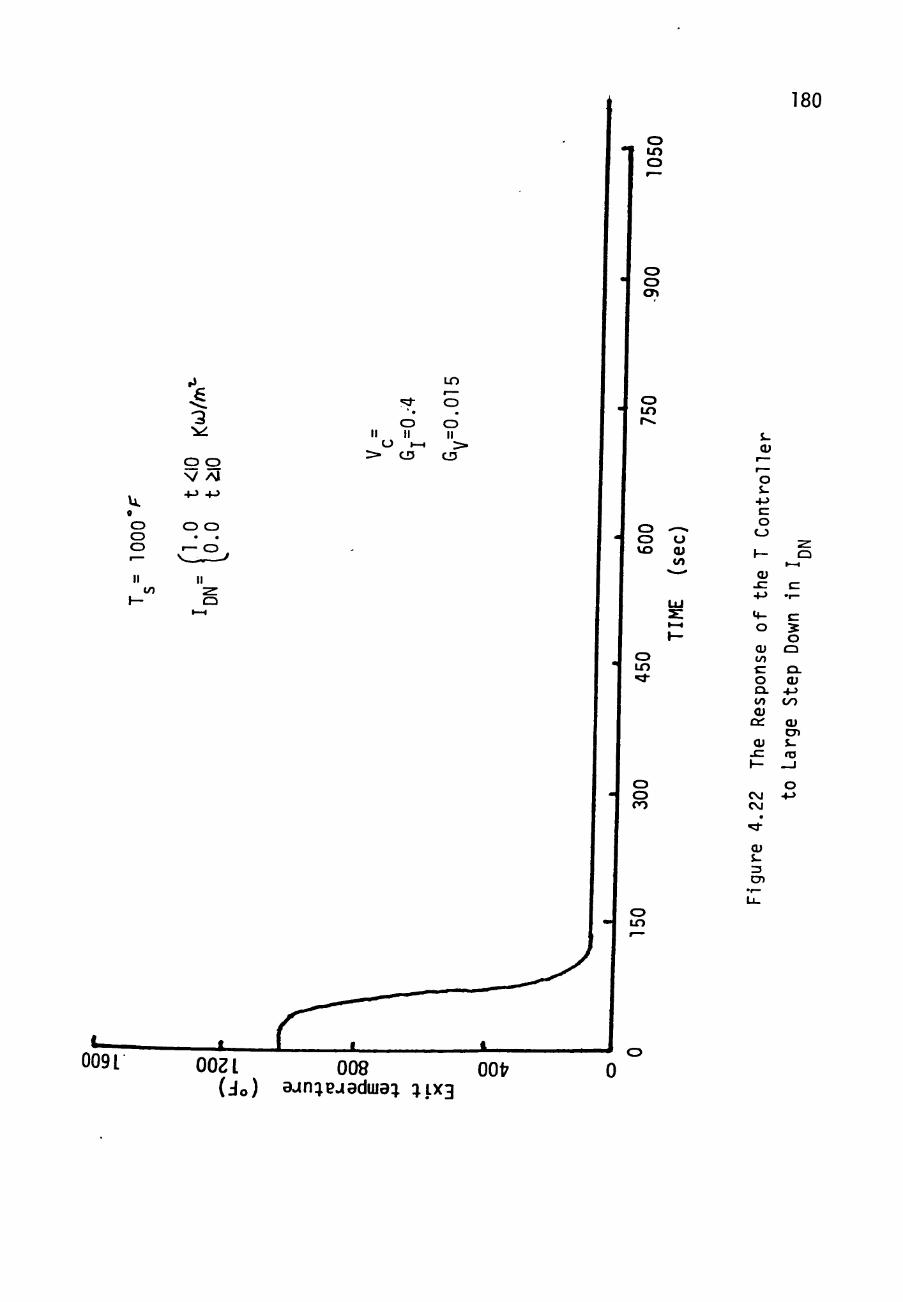
180
o to o
« o o o
3
o o V /M
O II II
O •—t > CD
lO
O
CD II >
CD
O O crt
o i n
t/) Q
O CD VO
U cu
J -cu
o S-
4-> E o
CD
CU s: a 4-> • ! -
CD in
o o CO
M-O
CU to E o QL to CU
CC
Qi SZ h-
CM CM
•
CU J-3 CD
E S O
CD
Q . (U
-t-J OO
Qi CD S-ro
1
O •4-J
0091 (Jo) 9-in:jpjaduja^ :^LX3

181
o i n o
o o cn
CD LO CM
II O
>
^ •
o II
(—1 CD
O •
o II
CD
0091
o i n r^
o o t o
o LO «:*•
o o CO
^—> CJ CU to
" ^ • ^
LU s: t—•
1—
on
tro
lle
r
CD
\—
Qi JE 4->
^-O
CU to E o a. to cu
CtZ
Qi . E 1—
CO
re
4.2
z: CJ
I - H
E
CL ZJ
o. E ro
Q :
cu CD
ro _ J
o +->
CD
CD i n
OOZL 008 OOfr (Jo) 9v»n:^ejaduja; : LX3
o 0

182
o o CM
o O O O o
o +->
cu to E o Q. to CU
DC S-
cu
o J -
4-> E O
CJ
E
O Q
ro CC
CU CD
^ S-CM ro
CU i -3 CD
0091 OOZL ( Jo )
008 00t7 ajn:jpjadiiJ9q. :^LX3
0

o i n o
o o CT»
183
o LO CM
II O
>•
" * •
o II
1—t CD
LO O
• o M
• * !
CD
O i n r
^ o t o
CD i n
':;r
o o CO
*•— u CU tn
• ^ - ^
LU S i—t
I—
ntr
olle
r
o t_3
h -
CU . E +-> M-O
Qi to E O Q . to Qi
CC
Qi SZ 1—
LO CM
«et
Qi S-3 CD
C I -H
c
V) E O
+J ro
^~ •r—
o to o + j t/) ro
LL.
^__ ro E
OO
o
CD LO
009 L OOZL • 008 0017 (Jo) 9«»n:;ejadui9^ ^1x3
0

184
o i n o
o o CT»
i n
o ^ o i n CM o o
O I—I > >" CD CD
o i n
E •r-to
O
O + o o to
to
•
o o vo
o i n «*
o o CO
'""^ o cu to "-
LU S •—I
1—
Qi 10 E o o. to Qi
DC
S-Qi
t—
t—
O s-
+J E O
CJ
h-
vo CM
• «;J-
Qi i-3 CD
s ^ CJ
I - H
E . r—
to E O
• f—
-M ro
^^ r— . f —
U to o
ast
LL.
Qi CD t -ro
—J
o i n
0091 OOZL. 008 0017 (Jo) 9^n: euaduj9:; 1.1x3
185
o ^ i n CM o II II
CJ • - . > cn
i n CO
o II *>.
CD
009 L
o i n o
o o
•
o LO
CD CD
vo u (U to
i. Qi
o •M ^ E CJ O I-H
O E
a;
CD i n
cu to E O Q . to CU
OC
to E O
• I — • ! ->
ro
O to
O
o
o CJ CO
cu 00
ro r CM
• <d-
cu J -3 CD
E oo o
•M
CD LO
OOZ L 008 0017 ( J o ) 9un:^PJ^duJ^:^ 5.^x3
0

4-> o to
o LO CM II
O >
•vf •
o II
1—1 CD
LO O
. o II
CD
o O O O
to
o + to
• o II
to Q
o tn o
186
CD CD cn
o LO
CD '—-CD O to cu
to
CD LO
CJ CD CO
J^ cu
r—
— O s-
+J E O
CD
I—
CU s: +-> ^-o CU to E O C^ to cu
CC
Qi sz \—
CO CM
• "Cf
cu S-3 CD
•r—
u.
c 1—1
E ••-
to E O
•r— •4-> ro —
t— •r—
o to o
s o ^— oo cu CD S-ro
_ J
O +J
CD LO
009 L OOZ L 008 0017 ( J o ) 9.4n:;BJ9diu9:^ :^LX3
0

187
when these values are used during the ind ica ted I
va r i a t i on . Also shown in Table 4.1 i s the response of the
system t o changes in the se t point temperature.
Figures 4.29 and 4.30 show the response curves for these
va r i a t i ons . Other f i g u r e s , in Appendix H, show the
temperature behavior for these 1^^ and T changes whenever
other values of G^, Gj , and V a re used.
4.3.2 The M C c n t r o l l e r
The H Con t ro l l e r (Figure 4.31) operates on tiie
pr inciple t h a t i t can pred ic t the mass flow r a t e necessary
for a c e r t a i n ou tput s t a t e a t the so l a r boiler if i t knows
the Ipji and N - ^ va lues- This predic t ion i s accomplished
by the use of the RFC equat ions in Appendix B. If the i n l e t
valve behavior could be modeled with 100?i ce r t a in ty then the
exact ac tua t ing s i g n a l t o cause the predicted flow r a t e
could be computed. However, experience indicated tha t the
exact behavior of the valves cannot be described with
las t ing accuracy. For one thing, other valves in the system

188
o •1 in
o
o o cn
4->
O
o O CD
A)
o O CD LO
CM
to
cn CJ
II
^z Q
O CU to
cu
o s-
4J E o
CJ
(U s: 4->
CU to E O Cl. to cu
OC
Qi
cn CM
cu 3 CD
to
E
o CJ
CL Qi
•*->
cn Qi CD i-ta
o • M
0091 OOZ L 008 0017
(Jo) 9-»n:^ejaduja:; :}LX3
0

189
o • I LO
o
o o cn
o lO r
V +->
50
0°F
II
A\ 4-5
U_ O o CJ o • "
to
CM E
.9 K
W/
o II ZL
o
O ^ LO LO . O CM O
O II II II
U t—I > > • CD CD
0091
o o to
o cu to
o LO
CJ o CO
i . Qi
o S -
+-) E o
CJ
a; JZ • M <+-O
CU to E O ex. to cu
DC
Qi
CJ CO
CU J-3 CD
to
o. cu
OO
CU CD i . ro
CD LO
o OOZ L 008 0017
(Jo) 9-in:^pjadiua:j :^LX3
0

190
V-J I I
u ro O
to ro CU
S -
cu
o s-
4-> E O
CD
CU
CO
cu S-3 CD
rx~inn?r

191
sometiae c a u s e t h e i n l e t va lve M versus V curve to change.
Also, with t ime , va lve e r o s i o n and d r i f t in e l e c t r o n i c
elements in the a c t u a t o r cause the M versus V curve t o
change. T h e r e f o r e , feedback i s s t i l l d e s i r e d in the rt
c o n t r o l l e r .
The feedback s i g n a l in t h e M c o n t r o l l e r i s the mass
flow r a t e r e a d i n g t o a b c i l e r . The reason an rt c o n t r o l l e r
has never been u t i l i z e d a t the ADVS i s because ao r e l i a b l e
feedback s i g n a l a t t he low flow r a t e s c a l l e d fo r i s
a v a i l a b l e - However, with t he l a r g e system flow ne te r
producers have a s s u r e d much g r e a t e r r e l i a b i l i t y from the
flow meters-
The feedback flow reading i s used to de r ive an e r r o r
terra:
e = ( M Q / M ) - 1 (4 .20 )
where
fl = t h e flow r a t e des i r ed by the RFC equa t i ons
M = t h e measured flow r a t e t o the b o i l e r .

192
T h i s e r r o r t e r m i s u s e d i n much t h e same way a s t h e ^ t e r m
of t h e T c o n t r o l l e r - T h a t i s , t h e a c t u a t i n g s i g n a l i s
c a l c u l a t e d b y :
V ( t ) = < V > ( t ) - Ke ( 4 . 2 1 )
where <V> i s found by E g u a t i o n 4 . 17 . The v a l u e s of V and
<V> a r e s t i l l c l i p p e d t o r e m a i n w i t h i n 0 t o 100%. A l i s t i n g
of t h e c o m p u t e r c o d e f o r t h e M c o n t r o l l e r i s found i n
Appendix G .
The M c o n t r o l l e r was t e s t e d a g a i n s t t h e same Igt. and Tr
v a r i a t i o n s a s t h e T C o n t r o l l e r . T a b l e 4 . 2 shows t h e
f a v o r a b l e v a l u e s of K, and G f o r t h e s e c o n d i t i o n s . I h e
ITSE was a g a i n f o u n d by E g u a t i o n 4 . 1 8 , a n d t h e maximum
t e m p e r a t u r e o v e r s h o o t was a g a i n l i m i t e d t o 1260 F-
F i g u r e s 4 . 3 2 - 4 . 4 1 show t h e t e m p e r a t u r e r e s p o n s e c u r v e s f o r
each o f t h e c o n d i t i o n s i n T a b l e 4 . 2 . A l s o i n Apper .d ix H a r e
F i g u r e s s h o w i n g t h e r e s p o n s e of t h e s y s t e m wi th M c o n t r o l l e r
us ing v a r i o u s o t h e r K a n d G v a l u e s .

Table 4.2
Favorable Parameters for the M Controller
193
" J ^fo.oi t<10 ^^ l i .o t^lo
Tg= 1000
^ I =0-0 t<io ^ lo.oi t>10
T^= 1000 3
Ipj^=t/1200
T = 1000 s 4
Ip^=l-t /1200
T = 1000 s
V.9+.lsin(f^) T3=1000
\ ^ = . 6 4 - . 4 s i n ( ^ )
T =1000
7 ^ Io^^=.9+.lsin(gQ)
T =1000 s 8 ^ Ij3^=.6+.4sin(gQ)
T =1000 s
J OOOO t - ' lO
H 500 t ^ i o ' " I = 0 9 DN ^'^
J ^C500 t < 1 0 s (lOOO t > 1 0
K
100
100
20
5
20
5
5
100
5
100
Gw
0.8
0.8
0.8
0.2
0.8
0.2
0.8
0.2
0.011
0.5
ITSE
9.2 E9
385,4:E9
83.8E9
42.2E9
15.9E9
22.9E9
20.8E9
2.1 E9
•2.4 E9
22.5E9
'MAY
1000
1000
1184
1260
1260
825
1260
1077
1000
1259

194
o i n o
o o cn
o LO
o O o o
o o
-M +->
O O • •
o -—
II
o CD — II
l i ^
0 0 •
o II
CD
to
CJ o vo
o cu to
LU
o LO
o o CO
CD to
009 L OOZL 008 0017 (Jo) 9wl : euadLua: :n.X3
0
s-cu
r— r—
o S--M E O
CD
:E
cu sz +-> V*-O
CU to E o Cl-to cu
Q :
cu - E 1—
CM CO
• ^ CU s-
^ 1—
I-H
E •r—
CL =3
O . CU 4-» OO
CU CD J-ro
_ J
O • M
CD

195
o tn o
o o en
O 00 o I— o II II v: >
CD
o O CJ o
o tn s-
cu
o S -
+-> E o
CJ CJ o to cu
to
to
o LO
o CD CO
cu - E •M
H-O
CU to E O Q . to CU
DC
Qi SZ \—
CO CO
• 'd -
<u s_ 3 CD
E • 1 —
E 5 O
Q
CL <V
-M OO
CU CD J-ro
_ J
O •4->
CD LO
009 L OOZ L 008 0017 (Jo) aun:^ejaduja:t :^,LX3
0

196
o LO o
•
o o cn
CD LO r>.
cu to
cu
o s_ 4-> E o
CJ
cu
*4-O
cu to E O Q. to CU
DC
Qi
CO
CU
s-3 CD
ro CC
CU CD J-ro
009 L ) aJn: eJadllJa: :;,LX3

197
o i n o
o o en
CD
m
cu
o o o o
o o CM
4-> I
o cu to
o S -
• M E
o CD
:r Qi
«4-O
CU to E O CL to (U
DC
CU j ^
1—
LO CO
•
CU S-3 CD
E S-O
CJ
a. F ro
OC
Oi CD S-«o
_ J
o • M
009 L (Jo) 9un: euaduJa: :JLX3

198
o i n o
o o cn
Ll_ o O O O •—
II to
1—
+-> v» o
I, E
• f—
to —-
. CJ
+ cn •
CJ
II •z. Q
0 0 CD CM O II II
^ > CD
O LO rv.
CD o to
o cu to
o LO
o o CO
o lO
009 L OOZ L 008 0017 (Jo) 9un:^euadiija:^ :^_LX3
J o 0
s-cu
r— r— o S--M E O
CJ
s: cu
JC 4->
M-O
CU to E O CL to CU
DC
CU SZ \-
to CO
^
cu S-
z: Q
1—t
E •"-
to E O
• r -4-> ro
t—
1—
• 1 —
O to o
+-> to ro
LL.
1 —
— ro E
OO
o • M
CD

199
o i n CD
CD CD
cn
CD LO r>.
CD CD t o
LO II
:^
CM
o II
CD"
o cu to
o CD O O
to
CJ + vo o II
CD LO
to Q CJ CD CO
s-cu
r— — o i -
+-> E O
C J
2 :
cu J Z
+-> <4-0
CU to E 0
a. to
cu CC
Qi - E 1—
r CO
«d-
cu I -3 CD
2r CJ
t—t
E •>-
to E 0
• 1 —
•J-J
ro r— 1 —
• 1 —
0 to
0
• M to ro
Li
eu CD J -ro
_ J
0 +•>
CD LO
0091 OOZ L 008 0017 (Jo) 9un:;ejaduja:j :;_LX3
J o 0

:uo
o i n o
•
o o cn
o LO
0 0
LO CD II II
CD
U)
O CD VO
O CU to
o
000
II t o
J—
•
9+0
o II
z: CD
o LO
S-cu
r— f ^
O J-
4-> E O
CD
2 !
CU JZ 4-J
<4-O
CU to E O o. to a
DC
"z. CD
1—1
E ••-
to E O
•r— 4J ro —
r— •r— U to
O
^ O
CU tn
o o CO
00 CO
cu S-3 CD
ro E
t/O
o 4->
o LO
009 L OOZ L 008 0017 (Jo) ajn:jeJaduJa:^ : _LX3
0
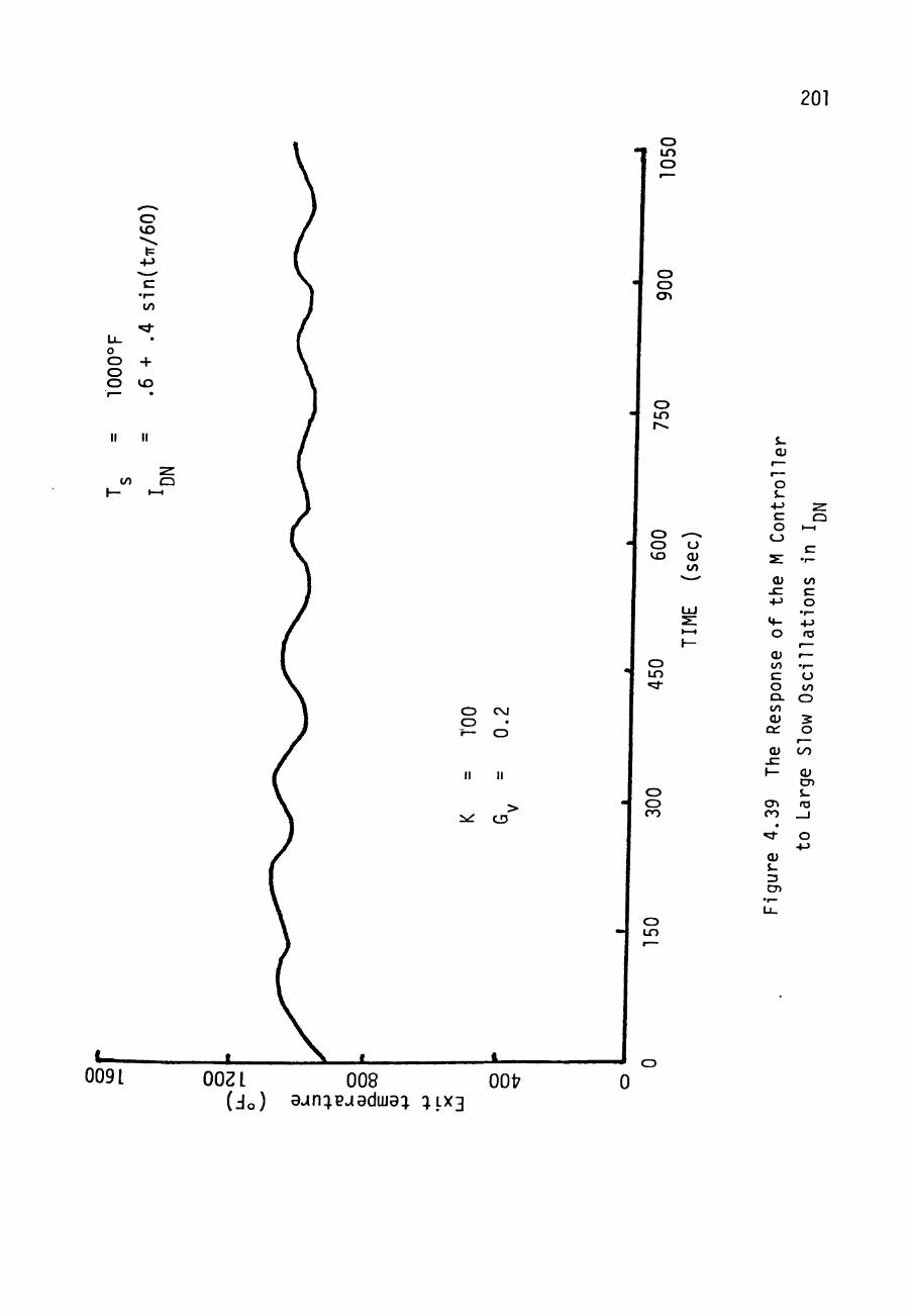
201
o t n CD
o vo
t= 4->
E •r—
I/)
O O + O
o vo
o CJ cn
to a
CD LO
CD CD t o
o cu to
.
O CM CD r— O
II II
^iC CD
CD LO
CD
^ o CO
J -
cu 1 —
r— O s-
4-5 E O
CD
s: cu
- E
+-> *f-
o cu to E
o CL to CU
C3C
Qi jz: \—
CD CO
• ^
CU S-3 CD
C 1—1
E • ' -
to E O
•r— 4-» ro
t—
r— •t—
U to
o s o
r-^ 0 0
cu CD S-ro
_ l
o -»->
CD t o
0091 OOZ L 008 OOt ( J o ) ^«ln:;eJ^duJa:^ : ; L X 3
0

202
o -I in
o
o o en
o in
LO
II
o o
II
C D '
V | A |
•*-> 4 ->
CD CD VO
U CU to
o LO
o o o o
o o o in
cn CD
to
o o CO
cu
o S -
• M E O
CJ
cu s: +->
M -O
CU to E O a. to cu
DC
Qi
O
CU i -3 CD
to
o CJ
a. cu
4->
(n Qi CD j -ro
O • M
CD LO
O
009 L OOZL 008 0017
(Jo) 9^n:jpuadLija:^ : _LX3
0
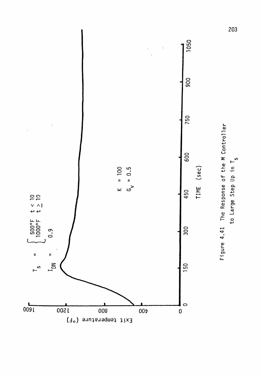
203
o •t in
o
o o cn
o LO r«^
o in o I— o
II II
^ CD
O O
V A I
CD CD t o
U CU to
CD LO
4-> 4 J
U_ L l .
j 50
0°
1000
°
II
to
•
0.9
II
CD ' I-H
i • ^ •
-
•
s. cu
r—
^— o $-+J E O
CJ
2 :
CU . E +-> Cf-
o cu to E o CL to Qi
CC
t \-E
•r—
Q . ZD
Q . CU
- fJ OO
CU CD S-ro
to
CD CD CO
OJ
Qi S-3 CD
o LO
009 L OOZ L 008 0017
(Jo) 9jn:^pjadiua:^ :^_LX3
0

204
4.3.3 Comparisons Between T and M Con t ro l l e r s
A comparison of Tables 4.1 and 4.2 as well as the
f igures of the previous s e c t i o n s demonstrate acceptable
control of t he s o l a r b o i l e r s t a t e by a number of ways.
There are two reasons for favoring a T c o n t r o l l e r . The
f i r s t i s t h a t , even though Figures 4.20 and 4.31 do not make
i t obvious, the T c o n t r o l l e r requ i res l e s s memory spiace and
computational time than the M c o n t r o l l e r . The second reason
i s t ha t the M c o n t r o l l e r seems to outperform the T
con t ro l l e r i n only two cases . Both of these cases have
o s c i l l i t o r y I cond i t i ons . I t i s very hard to bui ld a DN
switching funct ion around condi t ions such as these s ince i t
cannot be known to be o s c i l l i t o r y un t i l a f te r the f a c t . I t
i s recognized tha t an M c o n t r o l l e r may reen te r the
considered c o n t r o l l e r s whenever the pressure cont ro l
guestion i s cons idered , but a t t h i s time the T c o n t r o l l e r i s
recommended.
The u t i l i z a t i o n of a switching function for the G
parameters in the T c o n t r o l l e r might be used based on large
pos i t ive values for the de r iva t i ve s in 1^^ . However, i t
does not appear to be necessary for the c o n t r o l l e r to switch
205
parameters i f
V = 250
^ = 0 .4
G = 0 . 0 5 .
This w i l l change t h e response l i s t e d i n the prev ious s e c t i o n
for only l a r g e s t e p s i n I^^ and t h e l a r g e f a s t l^^
o s c i l l a t i o n s . The response of the suggested c o n t r o l l e r fo r
these c o n d i t i o n s i s shown in F igures 4.42 - 4 . 4 4 . The
response has not s i g n i f i c a n t l y d e t e r i a t e d .
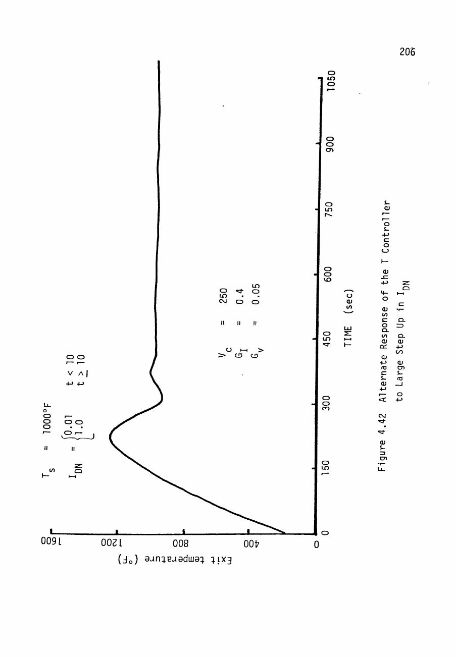
206
o •t in
o
o o cn
Qi
O S-
• M E O
CJ
CU
o cu to
+-> Cf-O
CU to E o CL to CU
DC
CU • M ro E S-CU
• M r— ca:
CM ^
• ^
CU J-
^ CJ
I -H
E •r—
Q. rD
Q L
CU +-> OO
CU CD J-ro
_ J
O +->
CD
0 0 9 L OOZL 008 (Jo) 9-in:;pjadiija: : LX3
OOt 0

o LO o
o o cn
207
o LO
O "51-i n CM o
II II
O t—1
> cu
0.05
II
> cu
V A I 4-> -»->
O CD VO
O CU to
o LO
o O O O
to
o o CO
o LO
O
009 L OOZ L 008 OOt
( J o ) a-«n:^pjadiua:j : ; L X 3 0
S-cu
r— r— O S-
+-> E O
CD
t—
CU - E 4->
M-O
CU to E O CL to CU
DC
CU - • - » ro E S-cu
• M r— <C
CO
cu J-
^ o
I -H
, E
E 5 O
CD
O . CU
+-> OO
CU CD i . ro
_ J
O +->
CD
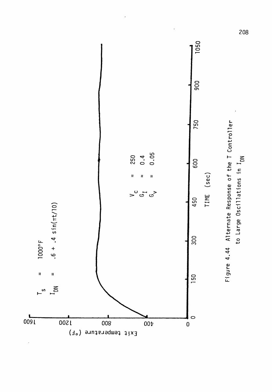
208
o •1 LO
o
o o cn
.
tn o ^ o LO CM O O
II II II
O I-H > > • CD CD
o o o o
4-> t=
E
to
+ VO
to
o LO r<
o CD vo
CD LO ^d-
CD CJ CO
o LO
^if-^^
u cu to
V <•
LU 2 : I - H
h—
J-cu
Co
ntr
oll
1—
cu JC •«->
«f-0
<u to E 0 Q . to CU
DC
Qi +-> ro E i-Qi
•»->
f —
< :
ure
4.4
4
CD •r— • t
^ Q
I - H
E •r—
to E 0
•r— 4-> ro
r— 1—
•r—
0 to 0
CU CD S-ta
_ i
0 +->
0 0 9 L OOZL 008 OOfr
(Jo) 9Jn:^pjaduja:; :JLX3
Jo 0

CHAPTER V
BECOHHENDATIONS
The f i n a l d e s i g n of t h e S o l a r F o s s i l - Hybrid P l a n t by
t he C r o s b y t o n S o l a r Power P r o j e c t w i l l be u n d e r t a k e n in t h e
next few a o n t h s . The r e s u l t s from t h i s s t u d y p r o v i d e u s e f u l
i n f o r m a t i o n f o r t h e f i n a l d e s i g n . S e v e r a l s t r a t e g i e s f o r
o p e r a t i n g s o l a r b o i l e r s have been i n v e s t i g a t e d and two
t a c t i c s f o r c o n t r o l l i n g t h e p r o c e s s l o o p of t h e s o l a r
b o i l e r s have been a n a l y z e d .
The s t u d y of o p e r a t i n g s t r a t e g i e s i n c l u d e d f i v e m u l t i -
mode s t r a t e g i e s . The n o s t f a v o r a b l e s t r a t e g y i n t e rms of
annual s o l a r p e n e t r a t i o n and s o l a r b o i l e r l i f e t i m e was t he
DAQ s t r a t e g y . Th i s s t r a t e g y h a s t h e s o l a r b o i l e r s p roduce
500°F, 900 p s i a w a t e r t o be used by t h e f o s s i l b o i l e r . I f
too much w a t e r can be c i r c u l a t e d th rough t h e s o l a r b o i l e r s
( l i m i t s e t by maximum f low r e g u i r e d by the t u r b i n e ) , t hen
some of t h e t o i l e r s a r e s w i t c h e d to t h e 700 °F, 900 p s i a
A u x i l i a r y Mode. The number of b o i l e r s s w i t c h e d t o t h e
209
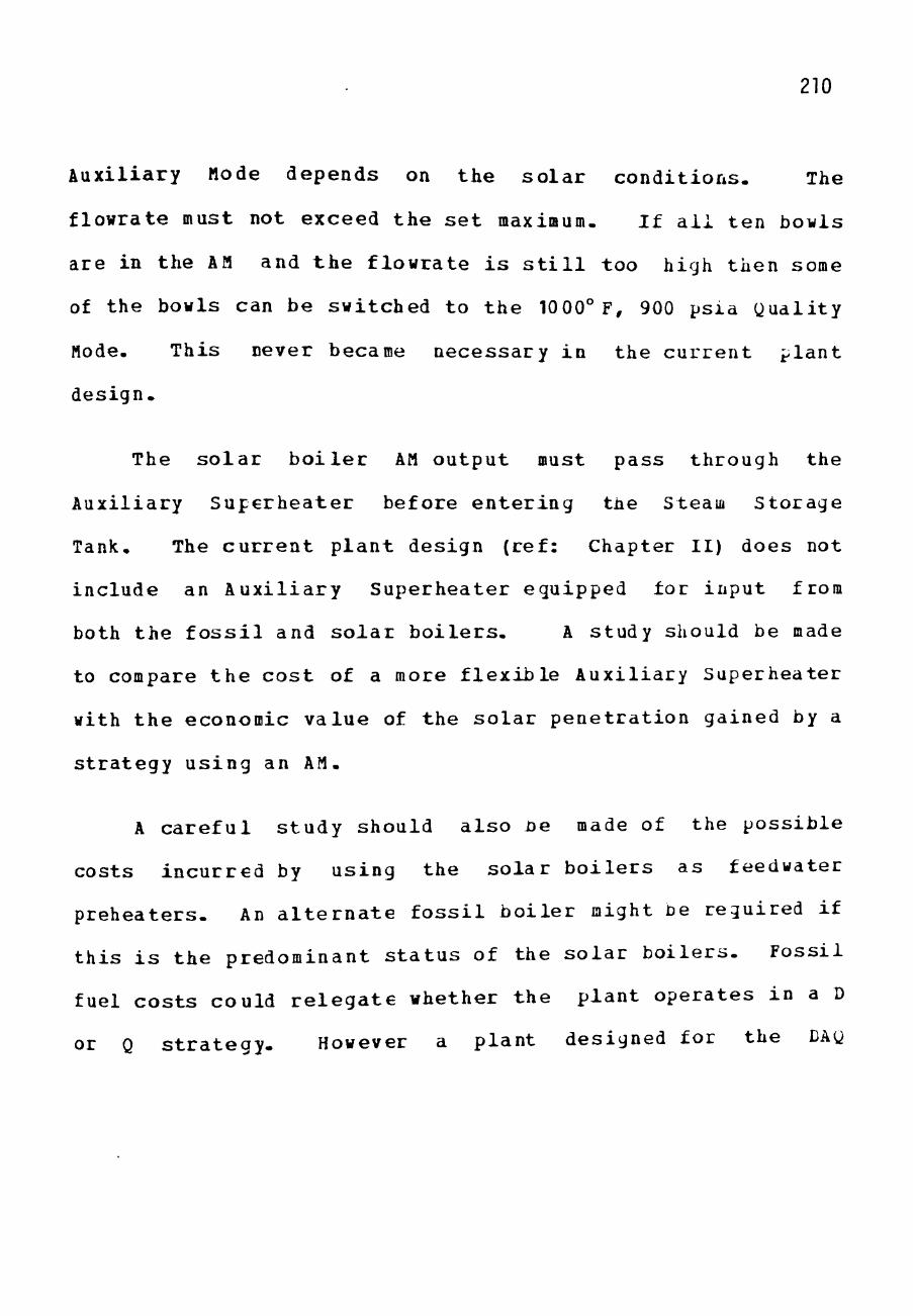
210
Auxi l i a ry Mode depends on t he s o l a r c o n d i t i o n s . The
f lowra te must not exceed t h e s e t maximum. I f a l l t en bowls
are in the AM and t h e f l o w r a t e i s s t i l l too high then some
of the bowls can be swi tched to t h e 1000° F, 900 ps ia Qua l i ty
Mode. This never became necessa ry i n the c u r r e n t p l a n t
des ign-
The s o l a r b o i l e r AM ou tpu t must pass through the
Auxi l ia ry S u p e r h e a t e r before e n t e r i n g the Steam Storage
Tank. The c u r r e n t p l a n t design (ref : Chapter I I ) does not
inc lude an A u x i l i a r y Superhea te r equipped for inpu t from
both t he f o s s i l and s o l a r b o i l e r s . A study should be made
to compare t h e c o s t of a more f l e x i b l e Auxi l i a ry Superhea ter
with t h e economic v a l u e of t he s o l a r p e n e t r a t i o n gained by a
s t r a t e g y u s i n g an AM.
A c a r e f u l s t u d y should a l s o he made of the p o s s i b l e
cos t s i n c u r r e d by us ing the s o l a r b o i l e r s as feedwater
p r e h e a t e r s . An a l t e r n a t e f o s s i l b o i l e r might be r egui red i f
t h i s i s t he predominant s t a t u s of the s o l a r b o i l e r s . F o s s i l
fuel c o s t s could r e l e g a t e whether t h e p l a n t o p e r a t e s in a D
or Q s t r a t e g y . However a p l a n t designed for the DAQ

211
strategy needs only software changes to operate with the QAD
strategy.
The study of strategies also lead to other possible
changes in the plant design. Highly significant results are
shown in Appendix D which could promote altering the number
of Solar Gridirons utilized in the plant. This study shows
important penetration per Gridiron values for the DAQ
strategy- These values in consideration with economic worth
of solar penetration and capital cost of Gridirons should be
carefully reviewed before the final plant design is done.
Without considering the cost to build a Gridiron, the
results indicate that 18 Gridirons should be incorporated in
the Hybrid plant. This is because a good value for solar
penetration per Gridiron, 1.43, is availible with 18
Gridirons. The plant with 10 Gridirons does get a
penetration of 1.62/Gridiron; however, the total penetration
(continuous load; turbine 1) is only 16-18 compared to the
18 Gridiron total penetration of 26. 12-
Whichever strategy is chosen, the fluid exiting the
solar boilers must be controlled at certain temperature and

212
pressure l e v e l s . The f o s s i l bo i le r works to regula te
p ressure . The i n l e t va lves to the s o l a r bo i le r s regu la te
the mass flow ra te of feedwater through the bo i l e r s and thus
the temperature e x i t i n g the b o i l e r . Two t a c t i c s for
con t ro l l i ng t h e i n l e t valves were s tud ied . The f i r s t , the T
c o n t r o l l e r , which c o n t r o l l e d the e r ro r between the desired
temperature and the measured temperature seems more su i t ab l e
than t h e second which con t ro l s the e r r o r between desired
mass flow r a t e and t h e measured mass flow r a t e . I t was a lso
noted t h a t switching the parameter values in the T
con t ro l l e r scheme based on inso la t ion behavior does not
s i g n i f i c a n t l y improve the response of the so lar bo i le r ex i t
temperature. Therefore , a T c o n t r o l l e r with one set of
parameters i s recommended-
This recommendation provides information for the memory
space which the p lan t conro l l ing computer must have-
However, f l e x i b i l i t y must s t i l l be provided since the actual
plant b u i l t might s i g n i f i c a n t l y a l t e r the system model used
to analyze the c o n t r o l l e r . A change in the model might
r e su l t in t h e d e s i r e for d i f f e r en t T c o n t r o l l e r parameters
or even t h e use of the mass flow r a t e c o n t r o l l e r . Also,

213
there are other control schemes which have not been studied.
Ihe present study does indicate that either a T or «
controller can do an adequate job of controll ing the solar
boiler out let temperature-

REFERENCES
(CP 8) "The Crosbyton Solar Power Project," Volume VIII: Preliminary Design of 5 MWe Solar-Fossil Hybrid Electric Power Plant at Crosbyton, Texas, Texas Tech University, Lubbock, Texas, USDOE Contract No. DE-ACO4-76ET20255, February 1982.
(HS) Shankar, Hariharan, "Simulation of the Receiver in a Fixed-Mirror Distributed Focus Solar Power System," M.S. Thesis, Texas Tech University, Lubbock, Texas, August 1981.
(HL) Leung, Hip Sum, "Optical Power Concentrations on Aligned and Misaligned Receivers in Solar Gridiron Power Systems," M.S. Thesis, Texas Tech University, Lubbock, Texas, August 1978.
(RC) Reichert, Dr. John D. and Clements, Dr. L. Davis, "Informal Description of the Performance of a Solar Gridiron Collector/Boiler," CSP-RPS-1, Texas Tech University, Lubbock, Texas, December 1978.
(ST) Reynolds, William C , "Table B-2; Properties of Superheated Steam," Thermodynamics, second edition, McGraw-Hill Book Company, pp. 466-467, 1968.
(CP 7) "Crosbyton Solar Power Project," Volume VII: Performance and Cost of Solar Gridiron Electric Power Plant, Texas Tech University, Lubbock, Texas USDOE Contract No- DE-ACO4-76ET20255, February 1981.
(KW) Watson, Karan, "Performance Analysis of a Solar Gridiron Design Verification System," M.S. Thesis, Texas Tech University, Lubbock, Texas, May 198I.
214

APPENDIX A THE TMR EQUATIONS
Key: M = mass flow rate of the fluid through all tubes of
the solar boiler (Ibm/hr) 2
Ij = direct normal insolation (KW/M )
^ = solar inclination angle (degrees)
V„ = wind speed (MPH) W
(X = the Solar Bowl's attendance factor (\initless) 2
Ang= nominal gross aperture area (ft ) 2
' . e x . n Ol TAo KBtu M C = c o n v e r s i o n f a c t o r : 0.3170 8 KW f t^ hr
P = power (KBtu/hr)
Equat ions:
Y = M/(300 Ij^^)
Sl^ = S/15'
Power t o t h e w a l l of t h e r e c e i v e r , P^ :
PQ = C AngO<Ij^j^ cos J ?
P = P B. ! Ld) W 0 i n ^'
where B. is the multiple reflections factor m
Bi_ (i))= 1 - (0.045jp) / (1 + 0.972jp^)
Power lost by convection, P^L-
^CLM= 1 + 6 exp[-1.1705 Yl
p n 1-75
CUl= 1 + 0.366j;p
^CLW= 0.267 + 0.733 (V^ / 10) 21S
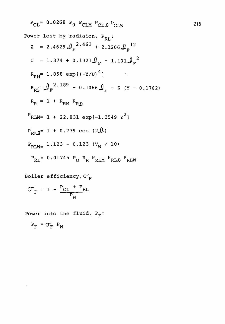
PCL= 0-0268 PQ P C L M P C L ^ ^ C L W 216
Power l o s t by r a d i a i o n , P : RL
Z = 2 .4629 J l^^-"^^^ + 2 . 1 2 0 6 j ^ - ^ ^
U = 1.374 + 0 . 1 3 2 l j l p - l . l O l J p ^
R^^ 1 .858 e x p [ ( - Y / U ) ^ ]
R = Jlp^''^^^ - 0 . 1 0 6 6 j l p - Z (Y - 0 .1762) Ril
^R " ^ " ^RM ^Ri).
^RLM= 1 + 22.831 exp[-1.3549 Y^]
Pj j = 1 + 0.739, cos (2il)
PRLW= i-.i ^ - ^-123 (V^ / 10)
PRL= 0-01745 PQ RJ V^^^ P J ^ PJ^^
Boiler efficiency, G „
Cr^ = 1 - ^CL " RL
Power into the fluid, P^:

Appendix B The TMRF EQUATIONS
The TMRF e q u a t i o n s assume a wind speed of 15 l MPH
Key:
T = Temperature of the steam exiting the solar boiler (°F)
T. = Temperature of the water entering the solar boiler (°F)
T- = Reference temperature, 100°F
M = mass flow rate of water through all tubes of the solar boiler (Ibm/hr)
2 I = direct normal insolation (KW/M )
J. = solar inclination angle (degrees)
P = pressure of the fluid exiting the solar boiler (PSIA)
PQ = reference pressure, 1000 PSIA
h = specific enthalpy (Btu/lbm)
To find the specific enthalpy for fluid with temperature, T, in °F and pressure, P , in PSIA:
1) Find the saturation temperature for P
^^ ,1400 - Px -3-7 ,1400 - P,4 ^SAT= 5^^ - ^^^ ^ 1000 ^ - ^^ ^ 1000 ^
2) If T<T3^^
h(T,P)= T - 32
3) I f T > T ^ , ^ A 1400 - P ^ _ ]50n - T D) ±T L ^ SAT, p = —yoOO ' " 1000
^ ^ ^ r.rr c f^ ' 140,^^4 h ( T , P ) = 1 7 8 5 + 1 2 . 5 p - (562 - 35p) t - 9 5 . 6 ( J^QQQ ^^
217

n 2^^ To find M(T^^ P^^ ^DN,'^ ^ ^^^ steam is being produced by solar boiler:
Y = (Tg - 700) / 150
AQ = 464.5 - 41.16Y + 2.475Y^ - 0.825Y^
BQ = 460.7 - 3.867Y - 14.6502Y^ + 7.0017Y^
* C = ^DN (^ -^O]^ 75)1-8)
M = M^[h (Tg, PQ) - h (TQ, PQ)]
Lh (T _, P^) - h (T^^, P )] E' E' 'IN' E'
To find M(500°F, P^, I ^ , ) when 500°F water is being
produced by solar boiler:
M^ = Ip^ (1513 - 1169 ('/ 75) ^'^)
m
M = M^, (h (T^, Pg) - h (TQ, Pg))
(h (Tg, Pg) - h (T.^, P^))
Range of validity for RFC equations:
The TFAP model as well as experience with the ADVS identified a range of J- and M in which it is best for boiler lifetime not to operate. This range is identified by:
and
where J ^ = 117 - T^ / 150 ^ ^
and ^ „.M ^ 40 (Ibm/hr)/ tube in the boiler.

APPENDIX C
THE POWER FACTOR TABLES COMPUTER CODE
The Power Factor Tables show the expected power in the
working fluid for given ^ , I^^, and outlet temperature for
solar boiler. The following code was used to calculate the tables.
In the code the RFC equations are used to find the required flow-
rate for a given inlet and exit temperature for the solar boiler
of a 200 foot diameter Solar Gridiron. The flowrate was found for
various inclination angles and insolation values for each exit
temperature. The data generated has been stored on a tape, CSPBF3,
kept at the Texas Tech Computer Center.
219

220
I
Hi
z *^ I
^ ' 1
flL t.M
t>o^-
t
I—ti/V
- C M
m o o •. 1/1 h-
•-• 1 T. • • X
^ M » »
<M 1 - 4 0 - 4 >0<Om-4 CO • • •
• • • • • • • »
• 3 • • • • •• •> « . •• rv -\ ri
.-•vOs}--4 ^ • • •
A I •
0 0 - 0
;23U.
rz-" « : > - < » -o r< » - Z o 2
< V _ l
'x i -JZ
o zz r
' > ^ ' - Z Z X UJO H - 3 > » - » - O • ' X •• u'><MtN'N<Nt/> ••CjU.t / )
z«-i?—UJ •—-o —>-cofvj>c—«NOr-«>-«Lnr-»-HUj .^•-•'jXh-o^in •'f-*z —*>-<f^rif\jo • ••ox
1 O m i A Z - 1
(j^ • • • ( \ j • fc • . • .
V i A c M f M f M
V) rt.
a c Z - X
<x-« 0 0 O X 3 XJZ CO
z o • X X - ^ a J O K t/1
V U J Z O
• • o r v j « M A i o n
• . - I f — Z > > • • •
o • •ur-Of^J
zn • - * •
Z V J UJ •.
CD TC oD t3 i o £ : : >v
= > : 3 D D 0 3 D n V ^ H — » - » — » — ^ H • • 13-E CD(13 OD-Q 31 O O
^-OOOCO O O O 0!A' ro o ^ O o t o -t •
> f m m N j ( \ » . - i * > ^ •
• II II II II II )i tl •-r^ 0-2:3 L u x x x x x x r o •• <zyD-i'y) < o •
_lt/> ot- j<z z z z z ZZ<-NIO X - f • f -<ct> I— Q Z X U J ' U ' J J ' i / ' U J U L U •. •» Z l / > Z ^ O O O L 9 i > O i ) ' J . T ) • L U L U < < Z Z Z Z Z Z Z > 0 0
_»> < U J < < X < < < < < i \ i o «-.nu.«-» x r r c r x r "O z < - (/>a::o'_)<Joooo-< •
• • •-» • N . O J h - > Q . O •• • • •• •• • • X O t ^ l A O C —« 'XOJ'ULUUJUJiUJJaOO •4A'-AiniA -* • i . iu j<NO x x x r x x r — « o
O LU K ^ • — H - V - " — r - m o — ^ n ^ •!-#
Z U . j < V - i — m < ' - : • • • • ••eg A H-. I—*-Z>"DD D Z ) 3 D • •
-• <C)a »—•O'—' . . • • . . . * -ij-* •r- v > < < x x x x x x r - o o 3 0 t / l • 0 < - < O a : Z ' - « ' A ' A ' A l A Z ^ r - L L - H O T H - l - l - l - H - r — J - O O O - J ^ - - - Z i O Z * " O Q • • r - r - > - h - > - i i A O C i ^ O 4/^lU ^ . - «
•-« x»-<o •?!»-• ro-^u-—*lA00moom • "O O^<-^P. I • •.-* D i y ) Q . - I K • • 4 - . - I r ^ r - V A O s l O • < ^ I A U I U S r U - U - l L U - U - U - L L — i •. :ozx:(/)u. •"-^^^mo •m » • • •a* •• • _J_IQUJ- - • « • - • •••
o«A3 -<r4Q.«.-azo •.».•. •._iiA'vji—<*-"-«i—ooooooooo t / > ' - < » H O < / ) Q 4 ' o o o • I A I A ! A I A ' J > • O - l O I > O O O O O O O m O »-»K » - 4 ( / ) K ^ — Z a L C D » - « — • O j ' N r j c v j Z f v J •"•-• C D — 1 » — ( M » - < O O a o r - l A tCvJ
< U L Q C < Z O U J » — S . i - l s O — • > 0 < ' S l A I D •) l l . Z f - < r H ^ • . - • 3 r i 5 D < 2 : c i f C 3 » - i • C 0 < Z a 5 U ^ m o O • t n o r o i L u l l 11 II II l | f l l l l r - « S ^ O > UJh-it /> — * - ! _ J Q • • • • Z Z f * - l l i X O a : » — K » - K K V - l - \ JJ • O T L U Q O O Z » - * 0 » - « • • • • • • • . C > - « l A L U > K Z U J l - i H - i > - » » - i t - H » - i i - t X K O O JJ • . U J I U _ l l u m < C / ) l A t A l A l A * - " • -3 f ' -« * - i U _ X X X X X V X O C 3 a i i x i a : » - » — < ^ — » — z < ^ - ^ • ^ - ^ - ^ — < ^ A < a J O ^ - u _ u J U J U J ' J J ^ J J U J l i J < < o Qfof a . . i i < Z ' ± i > - i Q - < » - « i — m c o m a o < « — • o > - ' - « ^ - " » — » — i — K I — i — K » — K ii Q . X ( - o > _ j > - « a : O Q - O < c o ! A m o z < f ^ i t > o u j X Q < < < « J J
K ( - i O UJ a : 3 • • • • t - iQ iAULiQ^aru j Q O C L • - •UJZO—J t-«_J O CDUJKtU r-«<\J m^^ lA-O f^ I X K ^ U J < X O Z < X < X t ^
o o o o o LXJ UL^<J<J<JL><.}LJL>l.y.JLJ
1
; 1
1 t t
i
1 t
1
i ' A ; 1*-' »
U-! '-J • Z
•—t '. ¥• i >N . r-1 (T-
m
•f
• .'^—• l A - ^ -J -V f • r-HJ_ O O
• z • * - •
l A — i f
r—)«A
: « • < 1
o r .3 w^z U - l - «
! a < i -• J 1
0 - * -3 Qu j y ) 1
" C X I - * iLOyico ;
o c o O f ^ '
Z - v)'-« O O m t - « O a f • K ^ D — < I J - J ^ O - J
OD^r* -O U - X I L •
-1 r* ' < i J Z ^ K^Z>0 • 1
' - J - H t n , I L K t O v O O x > o ^ m v-i »— UJ'-J 3
_ i > m - 1 Z < Z * ' ' X r - » O D — •
— « 0 ' A _ J a » Q t - * O - J X <U U U J • < » — t/>n[r'a: — 3 C 0 3 3 - ~ 3
' u — > ^ i : v -t / ) X O ^ f N I U J Z i-i>—UJ r^ j ^
OL • • - ' K X < — D h -<r < II cD>-( X S Z U L o : • 1 OJloC/i
'< V ' < X J ^ X < 3 - » ^ I A O L - U H - D <
lAv—'>trvj #00^ CD I/Is: r - t - t - ^oo >tco<<2<r
- " - J Z • *»i\ o»— r-t ,-• —. H-r—i- i O >-1/> Z 1 — <
II n o — 1 II ^.-aCV>'-« X
^ - ^ z o o ••-• o ot:*-•-•o«-« Q t Q c t : a j u >
O i A l l O — O i U ' j j O n f l S a ' o r - u . II II r - c D > < O U J
0 1 1 . 0 - X"-*!- a ^ a a z o ^ 0 3 c ^ - u t o o QO»-ia.a.Qz»^Zcic II a
1
0 » U J X M u i » - : 2 Q . U _
x<-o<o a. O O f - i - i X i i . (Nl i ( ro.'
o o o o o o o
221
Q
JJ
a.
J z
I , •u
irv
K v - i UL U
u. ; -I >^z
O. i Z X • - £ 3 — ^ •-• Q.>-» LL O O l A l L I I — OL O ^
• : i ^ : « - ^ II u j u j .-4 •
I A » " - J — - ) . ^ Z -JUJ O O t-H J . X M-H —« — • r * a — * • - < > — f — o u - j II II ^ - 1 3 : — z z - f i — •
o 1 : 0 - J II » - o a > ^ » - » Q.Q. Q .<U_ 11 .0 o i l OC U-
o a a . -J-x*-*
' J m
• (
^ X
Z 3
I "-•A
II
'A O - - - I
2-23 •• ^ X S.rM 13 • K -CD —
- ^ • • X
u. z -a
• - i II - -^
y > w
>• ^ o a . JJ •
Uziia.
X'JJA K 3 r ^ z: L U Z X
-tm z -»zm
3 • U»i-«lA o»—U. Z < " < ^ x
II
tAi
-5
<M
Z
n
ll
X
rvj
Z - Q
• t—<
(I - ^
_j_u . ; orujx)
JJO _JQ—I _ l •-
<zx • 5 - . m
O o.
3 Z -1 —< — O • -H —"n
•• o ^ h - x —» JJ < •.
• - l ^ < M Q . _ J ~ • o - J - o • J
o»i j . - i iu r ju jmxi tiiJLC\nj jji-^'.j ' ' - •_)^^_J.-#_J..^_|r-»_I^^_(,_# • i^ ^ - « Q - - " O - • 3 - » C - • 3 - » . D e n - • Z ' X Z X Z X Z X Z X Z X Z ' -U — — X - « " J »—•—• 1—»—I , ^ . , _ » >-»T\ •• Csi (J—J •*-' ^ 3 "CQ : r 3 2 3 T 3 Tt'*. r - « ^ ^ J - J " I — - - ^ ^ v^ . U J Z X i Z X i Z ' - U Z L U Z - U Z X ) —Nf -U2^t «-' O Z •• i Z 4 -Q ^ x i r i t j x i c t i i j j a f x i a JJO'JJ a'»"^J^->-«X'^ » — ^ • - • r - i X ' - i ^
- < ^ x l l } — \ - ^ X — i i H - \
o ^ ^ ^ < M r i m m > r ^ j - i A i A o ^ o m o - H • < ' — o - - •o»-» • • < ^ —'^H.-Ir-«>-«.-^—«—«.-(r-i^,-1-4 . o •>- - I X mr«-'—lA •— _ J x
' ^ ^ O f ' T r 3 ^ 0 3 t 7 G f ' 7 ' 2 r o " y x • • r * - o " - u r - L I ^ • • I A - y) •-x i ' j j i j j ' j j i u ' j j x i ' . u a J x i ' j J u j U L * — O r - t — ' - ^ 3 « - » - < — ^ ' - < ^ - —«
• • • • • > • • • • < • • • • ) — — . " ^ • »2r—>—<i—^- •>)— •• • _ l _ l _J _ l _ J _ J - I - I _ f - I _ l _ J - J < J J . - t < X > t ' - « L U X < i U i - « < X > t
- ^ ^ . ^ ^ — — . w ^ — S T J — I I 5 : o i j _ t - > — s i h - I I s i o x x a: ' - 'OJ a : lA > - z •-• 3 0^ >-• CM a: t A - - o Q
x x x x x x x x x x x x x a a : : ~ 7 0 • ' i A 3 a : z O a : ~ > 3 • ' ^ i — z K _ I-H I-H »-••-<»-) I-H I-H »-«»-< I-H -4 X "iZ • ^ X \ » - « O l £ X X 3 • X \ . - t t / > X
O l A o o o
O O
o
O O m
o r> m

222
M I t
1
\ J > _ . •
t J
K
z
z o HH *"^ K 3 Q
s: nc O X
F K »-—<
XIU_
0 . •"'JJ
O Q ^ Z 3
-*o •^
J J - * ' r -
» o zz Q » - " T •"-tUO • . — O X 3Ci 5 : 0 ( / l » - » M X
U- o UJ z
X I Z •- • Z « - i •« . - H K 2
! i 4
I
i
1 1
( 1
•
m * : • * ;
V • <f •
mr^ : ; • o
i # O ; > - » '
* o ; 00 •»• ;
• • ! 1 <\| f
! • * ' AJ *
» > : * • » • ;
r * > . f - * '-«»oao
' 1 lA'TS • O f - O r - f j - ^ . ^ t
• > ! • *
O N ^ X 0 + 1 o
• > v z O — I f * • - • I A • O > 0 »
«-<o-» o o \ 0 •con - » O ^ • 1
• •^J•mo o » - 1 1 <
•o_i'Ar-—' • — O Q O f * - • • • *
^ ^ • - " - ^ * l i J > ^ O Z
' 1 1
*
>4' • i *
K
* -^ *
• CJ
1! o. a. •— • » '
o 'A O P;
•' 1
a: K * •
0 6 Q j
• I A m 1 •
r j >o
• AJA •
•
n-OC
- »
•
o >f
. - . 4
1 UJ a. • » -
4-O I A 0^ O
• 1
'£ K * «^ r-*
CL
• 'r\ m 1 •
^J •O ' A .^^
C O — O 1 O O 1 O O O a C O
r-i
Q. r - « - I Q . , H l . — W * \ I A • - » — l A - ^ O X J aUJ
• 0 0 "JvO
Q . » - > N i a . ^ 1 1 1 t - ^ l
• •+ • + 0 • X
i
1
i
I
1
1
{
[ t
'. f
*
) •
4
' - .*
.30 •
» * X o z t - H
- ;<•
•
o >0
I - H
r H
1 •
m —«
l A . - 1 •
o o • O i A — O — ' f M o o i A O o o * .-i-»f m 4 ' l A 0 0 > i - f ^ 2 :
1 ; X I u
1 X X
1
1
• K K 1
i j j o o • *•) -<
, o • < : 3 ,
O.JLJ ' X t ' U
! cnz ' ; t o UJ ' • ar-x ! • O '' : O K ; ; o < i o r ' ! :s •
1 t z • i J 1 ^ _ 1
1 K < < !
' ' X ' 3
o ' z u j !
- • X 3Ch-
-^o — - l a :
• _ I G i < M D X ' m x 1 i / i ;
— Z U J < t . • - « X !£
O O K V - • v O — Q « J 1 1 z-u:^
0 0 < - i K O Xo: <co — X O _ J * — ^ 3 -X N . O O T
z 1 os - f -o roo-n -z O O C r v j x i j — O v O O X I . - < . - i p ^ . - i . - i II O O U J X II 0 3 < c v i • a : area _ii i i ..t>fHHK——r-i— cCD < z ' ^ H II l i II
l l l - t — > - • » - I I K O I - O o o If II II I I o a
Z>ooxi»-H i iu .ooxoc^a :Or - f 11 I I O O X O < t r H l - 0
Q ^ ' O O X O O ^ Q I K t — I I X J Z *^ Q^K>-»-«<£C2:a.a.K-xQ-Xxo2:xxX2:x</)QfX?x:uj
</) *-« X h -
I
1 f^ ^ H
3 0 x i - ^ x
> X -4 f - x s :
; I ;. !
; t
o OULJ

223
1
fU ; 'm
111 • Z
O U - l O
• -HJQ C L X
• " y i i l - I ^ S
<ax - -o O—«uj
Km>: •u. •>
*m • tl
• z 3 u O Q O • II D
a.x - ' I II
-J^T < 3 X K ""O O ' - ^ x ; K m c ^
• X »
; ^ II
m < i i ! i l
• i Z O t U 0 3 O * 11 ID
ax *m!i
—1»-»2:
<ox C ^ - u K m a :
• X •>
O'XJ p u j - 1 3 L i Q o •• o •• 1133 11 13
;!. J- Q - x »//> II . - i / i II
-ih-t-z —IK-?: < Q X < O X *— • • O I— "SO O—^JJ O^—JJ K m - j i ; ^mc^
• x^ » •u. » o o a " ^ - ^ o "H'A —. o g^ r> —«:> CQ • A — o (o u v ^ O 0 L ^ K O a - > t K JiA. 4 - K O f l L s J - K O a <J-K r s l l / V D O ^ c O O O O o O O 3 0 W < ) 0 3 JOt/OOO r-i O f A O ^ O A O _ ! O ^ O O O ' A O O O - A O UJ i l j l l •^JJ 11 II -OJ i n i .^JJ II II a JJ 11 II «. KOf iX I •+—O^'XI . . f - Q ^ i j »4_Q|^LU •4_£^UJ •> X U J f > U X I U ' N I _J U. UJrsI _J X tU^sl _ l X UJ ^ l O
Q.4/>HH</)Q.t/)»-t«/)a to* -«v ia - t / ) i - i ( / )a -co»-KO
< 2 ^ ^ < 2r>«f-M < z vf m < 22«f >r < z vf 'A f - M _ l o t - » - « _ l vO »-»-i_J >0 K » - i O >0 K<-i—l-O < < a i — < ' < c D — ' < < / i j . ^ < < n 3 — < < f O ^ -O K •• II O K • l l Q » - (.11 3 » — • . t l Q H - • . l l (/)«U'A _Jt/) UJ'A _|O0XI IA _Jt / )Xl iA _IC/>UJIA_I < f3^» i -a j < c x r ^ - a x f Y r ^ - x ' O s T ^ - a K a r ^ ^ ' j j t/> •O<r500 " O c C ' / ) •OcOoO •OcD' - / ) •'OoQ
• II U J ' A < II U J I A < ll U J I A < II U J I A < II I U I A < Z K II - I Z K I I _ I Z K II _ J Z K | | _ J Z K II _ i « /><_J ••CO < 0 • < > 0 < _ | • M / ) < _ J • • ( />< _ | •> 0 > O J U 3 > O H J 3 > 0 U J Q > O U J Q > O a J
t-fUJO. »-«'-iJa •" • IX IQL »-tUJQ. t-HXIQ. OcrTot < 3 of a : < Q a r o : «t Oofcx: < Q « i ^ < O o — l K 3 X - l » - 3 a I I - O 0 . - I K Q Q . - I K ^ II 11 K ^ II II K--« II II y-^ rt II »-• - • 11 II K O —J (D •-• O —I "J)«-! O O (C •-* O - i f l 3 <-• O O i ) t-« ooozooozooozooozoooz X > Q 3 t L > Q 3 X > a O X > 0 3 X > 0 3 o ' '-• r j m 4"
; m m ro ; II II : II
- Z ^ - -Z • ' Z Q o j O ' j J O U J - I Q - 1 3 - 1 3 o •• o •• o ^ 11 33 H :D II 20 o-x Q-X a x
•'Vl (I •C^ II •</) II - 1 ^ 2 : - 1 ^ 5 : _ j^ - t5 -< 3 X < O X < Q X »— ""O H- • ' O i— " O O ' - x i O ' -J iJ O - ^ J J h-rOa; h-mj< i-moi^
• X •> ' X •• • x » O cn lA-^ O CD 'A -^ JJ r O O ^ O Q. > J - t - O f l , 4 - K _ I C L 0 K r - o o o 3 (A c o o 3 aD t/1 m 3 o o i A o o c y - A o < O^O o JJ 11 il --JJ tl II . "K 11 II •" KOf'JU • •»—QOU •'TCctrxi •> X t U f v l - l XUiisJ _ l O X l r v I O Q. CO *-!(/) a . «/)•-«'/)QL t/)»-«vo
• •.•>> • . • •*/) •• • • ' / I ^ < z -<^-o < 2r>«: r - < t z >Kf 00 )—>-*_l>OKi-»—l>OK»-« - i O < •< aD "-^ < <CD —• < •< i U - -3 1 - • ' I I 3 K • " f^* - - " O0UJiA-J( / )XI iA _ J ( / ) U J O _ l <t 0^ 4 X l < OTvf UJ < Q Q UJ 00 • o o a t / ) • O c o o o ••mcD II U J I A < II U J I A < II UJsO<
Z » - II - I Z K II - I Z » - II - » » / ) < _ J • ' t /><—I fct/XO •• Q > O a i Q > « J UJ 3 > OiJJ
•-Hxia. I -HUJO- i - i u j a . o of c^ < Q a : cr: <f o OC QC < Q Q L _ I » - 3 Q . - I H - Q C L - J K
II II ~ II —• II II K ^ II II K«-« II II K O - I CD »-• O - l < D •-• O - I ro -H O O O Z O O O Z O O O Z X > Q 3 X > Q 3 X > 0 3 lA >0 S
X •
O
X
o X • o o
K. X «
o o X o o
X o o
X o o
4
i

APPENDIX D
STUDY OF NUMBER OF GRIDIRONS TO USE IN THE PLANT
As mentioned is section 3.3.2b, the DAQ strategy is a three
mode D strategy which utilized two modes when ten solar bowls
are in the plant. A study was made to see how many bowls caused
the strategy to utilize its third mode. This is also interesting to
see the solar penetration per bowl for the plant as the number of
bowls in the plant changes. This is a particularly interesting result
when the cost analysis of the plant is done. The additional solar
penetration a bowl can supply for the plant can be compared with the
cost per bowl.
In this study, the number of solar bowls available to the plant
was varied from one to ninety. The plant was operated in order to
have the maximum flow through the solar boilers without exceeding
59,000 Ibm./hr. Only three output modes are allowed, 500°F, 700°F
and 1000°F along with 900 psia.
In the cases where there were many bowls in the system, the
average solar boiler effeciency, <ar>, was fairly low. This condition
would threaten the boiler lifetime. Therefore, one more feature
was added to the basic DAQ strategy. This feature would not allow
the boilers to be operated in a mode which cause the boiler efficiency
to be lower than 50%. This efficiency limiting strategy is referred
to as the DAQ-SNAP strategy. The following figures illustrate many of
the results seen in this study.
224

225
-^_ ^ m' vpj ^rfW^'T^Eff^ 4-4-
^^SKSK^^CTF^"^iI
rrr;::::
~^nH^
1 — • — r ;:l: — 1 _ . . .
. • I . • • • i


228


APPENDIX E
THE STEAM TABLE CURVE FIT
Table G was generaged by Enayet Jiwani with the SAS program
at the Texas Tech Computer Center. The table applies to the
equation
T^ = a + bP + cP + dH + eH^ + fPH + gPH^ + hP^ + iH^
where
Tj. = temperature of fluid exiting the solar boiler (°F)
P = pressure of fluid exiting the solar boiler (psi)
H = enthalpy per unit mass of fluid exiting the solar
boiler (Btu/lbm)
230

231
X •JJ
DC O
O
UJ _ J CQ
UJ K CO
L L I
C I
• ^
cr>
M-
.93
2
^
1 ' 1
^ 1
• o CO
un vo
• • "
CJ
JD
K3
u^ cn o
• o
0 0 0 0 VO
• r^ 0 0 i n r—
• < 3 z:
cy l i j
f —
.855
«d-
1
CO ID VD
• • "
CVJ CVJ vo
• CVJ
1
CO ro r—
. o
CM r— r—
. CD O VO r ^
1
CVJ
618
•
r«^ O 1
• o ID r—
1 X
0 0 1
CVJ o
X
CVJ l o
ID X
CVJ
o o CD
1
CVJ o o o
\D
. f —
1
o ^ CO
• tn 1
CJ^ 0 0 vo
• - 1 ID CO VO
• VO 0 0
1
. rn
785
CM
1 j 1 t
-
..
cn CD CD CD
CD 1
CD CD CD
CD
!->.. CD CM
• 1
xn-• o
r^ r^ CM
1
oo CD VO
• CD
^d-CD ro
• uo ^3-1 ^
1
* ' ^

APPENIDX F
THE VALVE RESPONSE CURVES
Figure H shows the mass flowrate, M, verses actuator voltage
command, V, for the inlet valve at the ADVS. Two curves for
different days, July 5 and July 30, illustrate how the valve
characteristics drift from day to day.
Tables H-1 and H-2 were generated by Enayet Jiwani with the
SAS program at the Texas Tech Computer Center. The table applies
to the equation
M = a + bV + cV^ + dV^ + eP + fP^ + gT + hT^ + iVP + jVT + kPT
where
M = mass flow rate (Ibm/hr)
V = voltage command to actuator (V)
P = pressure of fluid through the inlet valve
T = temperature of fluid through the inlet valve
232

o 00
i n
•-J
OC o
OC =D O
DEV
o tn
JiC
••->
JZ
cn
M-
OJ
T3
O
-Q
1 1 1
ta
o "^ cy UJ
.113
in
1^ r— ro
•
r 1
en vo cn .
r— r— 00
r—
1
.135
o
•^ CM 1 —
. O 1
o 00 r •
I —
t—
^_
en o
•
ro cn
CM
1
.532
cn
in CD
-0.0
ro ro CD »
'
00 in en •
\D
r 1
vo in •
'd-00 CM CM
* ro
155
cn
ro
0.00
^ ^ CM .
o 1
CJ) r— 1 —
• CD 1
^_ r^ CM •
00
CD t—
cn •
^ 00 ro
^
554
• cn
ro CM o •
o 1
o in 1 —
• o
vo ^ ro •
LO r—
VO o in •
•^
1
in
392
•
r
0.00
^ r> in .
CD 1
CD 1 —
in •
ro r— 1
r r— CM •
CM VO ro
vo
774
•
CM
-0.000
00
0.03
CM
0.00
en
0.08
cn vo
-21.7
CM
.0000
vo ro •
CD '
in 00 CD •
o
CTi VO ^ •
o
r*. CM ro •
in CM r>.
r.
233

o CO cn
o ro
ID
CC
o
DC
o
STD DEV
_v
•>—)
- 1 —
sz
cn
M-
(U
"O
o
- Q
ta
EQ NO
21.3
37
-7.945
866.686
—
13.7
22
LL
L'O
-
8.17
2 307.057
CM
10.7
16
-.005
1.00
5 -70.406
2110
.301
cn
20.083
0.003
-0.226
-10.443
1041.049
«3-
10.860
10.863
-0.003
0.004
-0.3
18
-0.1
26
7.480
489.481
uo
0.004
0.19
5 -0
.317
-0
.127
7.869
462.947
vo
10.205
-0.001
0.083
.002
•
CD
-30.416
0.0002
-0.265
-0.1
05
-4.1
85
2604.442
r^
234
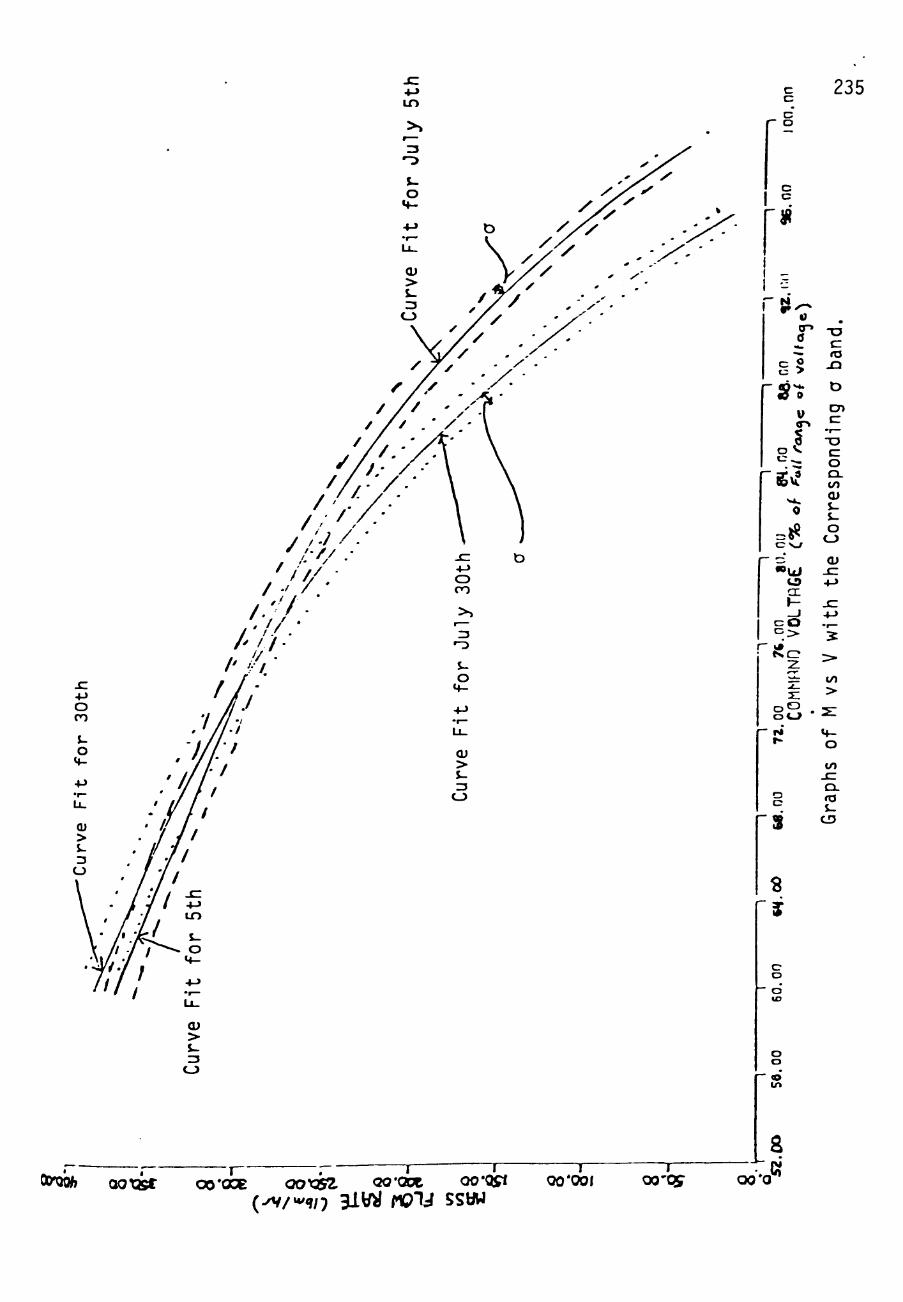
i n
OJ > $-ZJ
c c
o
c c
235
Oiyoi* aoxjst J J J—
OO'OOe. QOy^Stl QQ'OOt QO'QSi
{^/^in 3iy>i nO"U SSOW
^ » 0
0
**» g5
- » ^
a c:
"S
-;
< P V
ll 0
i C N ^
— c; fO
c c
- - k *
U i o a: h-_ i o >
N.Cr 2
o o
- r» t -
"S
«
- j
c o
•" o t o
o o
~ « i n
*-r-i ^
z: o o •
• • a c: ta
JD
D
cn cr 'r~-
-a c CD CL (/) OJ
o CD Qi
. C +-> JC +->
i >•
to >
2 1
«4-O
ta u CD
I 00*001 oo'cy
a oo-o^

APPENDIX G
THE CONTROLLER COMPUTER CODE
This computer used the ITMR equations to test the response of
the system to various transient conditions. The code listed is
for the M controller: however, by substituting the COMP M
subroutine with the COMP T subroutine, the same tests may be run
for the T controller.
236

237
J < a.
" . . . . . .^. . . " ^ * • ^ A r » r > i r « / ^ > n rf^lArf^tf^.^/^onx>.rtrtv^^lA^
•O
.•> •A N ") — A
t UJ
. r
r
^ J GO
II
O l
^ •< o
lA u
13
O i
I <— D Z - u.
. Q U J
>-»/>
<H
^ £ » >-« o o (M » 1
... Df Z a .-•
«« r> « > o » -*
o 'Jl
»><
•V -J :0 _J —-< A — I - O 4> ^ ••O .
• a f i - - I Z 2 - ~ V - • 3 > - r- - » t - .< • — I -» »— • - ^
»- oCi- 3 O "3 r— o a
. Q "XI I • *• a. — I - • if\
• - - . ^ • • i - » o a > » wj« — — • ri J\ o Z O > »- . « K o ^ o • 3 i l J O » ~ ~ O • «o — 2 _ 3 . I " H I M ^ . . < O * l_> M O h- 'H O) ^ * - '•* O O w U. * — Z " Z • T) < — o oDJO a. X . >- —-H o I - A 0 ^ 5 X *^ -< -< • • v — O » • - • J D . O Z • -I v s . . «) — CO ~ — I — o r-
Z o j - ^ •— »» (7>(> . ^ . . • ^ o> » 2 > -^ a. A •-• >si o ixj in in Of»i V • O N . IA— — o » . r - » m < af •-• o — . - ^ r H o I ' l A o ^^ —"w z — — <j-<»n -< X TT. i^-i- " O * ^ O K O • N < i A •t'O a " H - — - u > •
^ ^ - . .-.—.^4/> v-t.^ ' ^ o o • I K - . .HNfc *^ - * - ^ — * ^ . O o -J •-• —>Z — s < O K • . V < .^<M K _ J , f . K • K a f •-• I .-<K . 1-1 IA
-< O " O • (*>(•» — u . • . ^iw^ C I * - I — Z 1 K « ^ • O U £ a . Z O < N I Z * * K O . • » o o • v . — — — T O K — N . 0 - 0 OD Q r T — 1 U . - 1 T < < D » o < A n I -I . a . O T ""< — K — O O i J t - K l - X M/>—K 3 0 O • »VO »- . » — O — iB "Z " Z Q V Z — o •
(Dae—I—K • i/it/) a i A • • ( ^ — o D — o z K i - — . D O — • < - < • if> o ^ O i ^ D a C — ^ * I O • • o^^^^<^'-*'-* • »*-K<Mp-lTrf^ •'^r— r- O o j T t Z O » Q I > / lZ tr^ O . ^ ' ^ • . i O . o * ! / ) 1/1 > — — ro I I • »DO • — t / » A > 3 . > j _ i r i - — O r J O — O l - < — F H Z I — a c # z > - — T n f * — . O l i i A — o D _ i — . - l u j • ( > . (> .— o r - o i / ) . O • " O " X • y n / > o > ^ Q — u j a T — K K K . K ^ o it . ^
_J — I / I Z K I A O * • - ' U . » » 0 ' * - ^ • • ^ < » - l A O O Z . i - i a — > . M — K — — O t - i l l — • ^ O U J Z I - O M O II X • — CO—-0-»-0-<00 ' l A X • — 0 0 " * U . » : t - l - i O — Z K . IJUJ H O M O -^ir<K < < o O i - « « a c . r o > o — H o n r g . - i r - o > o — > A O S > K * # • of H O" II O " < u o i K t i D o ' - i ^ i A — m • — _ i 3C K n f i - i - v i u i r - i ^ f r i - * - r > — r v i r - . ii *< -< '^ i i i i o i ^ O aTKi - i < — • — o — > O Q f 2 i - « Q Z i > i . - « — K . o z < u j z ' . s .(M H—»^ i i . H . H p n o i A r . o f n i i K - J O i-t^^ . . - < K O » K M K fo O i i i o o o * o * o — O K 0 0 _ J ^ « / M i J a i r O 1 1 — t C — — II II 11 - ^ H K • . K O - ^ - ^ ^ ^ H B O ^ ^ K H 11 OT — Z — - i _ J _ J _ J - I I O II — I l r - K K K O K K —
-< aCO < K r K H Z — Z O f — U i O f Z O M < _ l l l M 3 < 0 H K K t M i n n » O - ^ O i j O Z - J — - l - l - I M Z <M—— — — — M T) U. <N Q. . • l u — Z i i — — o r — K X T i / ) ' X O > i i i - i — O u . ( O i / l 4 - < - l - < — 0 ^ « i / 1 Z Z r - < 0 4 > < 4 ' « O O O U - U u. i i O a i O < - < O O i - i
« r - a f " O — Q . K T X > K K K > l < 0 O O « / I Q . f t . K K O O K O H K O — U . — O O O J O X i - i I ' - ' — — K I S K O ^ I O «1 • • • •
_ l — 1 ^ 7 l i i T O O > K u . a r "A IA r- o o QJ ^4 -4 IN IA -J o o o
:£ -< rgrH j - i r t ^ K a x h O ^ r g f l - r i A - O K c o o o — < N i ( * i ^ i A O r - « ^ 0 - < r > j ' * < ^ m i O r - D f f - O — i N C ' ^ i A O K o n o - o — r s i « i K O o o o o o o o o —•-•r - — .-ii-i^'-<—'-<'^'^Ajr^rg<M(Mrx«V'M(»(<«>«»\fnfOr0'O /*< Ofn«r ^ . t ^ . / * J- T J J-iAiAU-iA a' o ooor ooooooooooooooooooooooo •JOiooooo oiooooc-Jiooc^or.oo o o ooocooooocooooooooooooooooooooooooo ooooooooooooooooo
-r
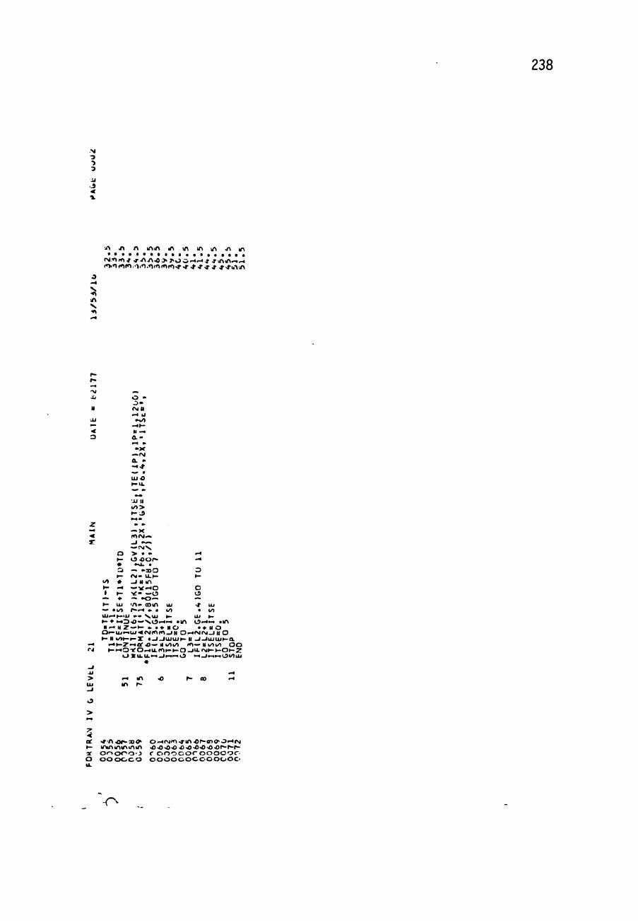
238
N
•J
^ i^ A lAiA lA 1A IA lA >A 10
rM.*»(»(^ J - - A i > 0 7>0 0 ' < ' - < * * X V i A — ^
O j
H
.IJ
.. < 3
0 » o» (MN -< U
• 0 - « K H — a.-.-« » • X —(M a. • — •t
UJO
Ol II «/)> K J
z • • - " — X < lOAJ— a: _i "—
O > . • '^ K O oor * -^ • »u. . Q — " j o O O K ( M - U . K K
</t * - J U lA K -^ — " ^ ' 4 0 O • K • ^ - — ( J O
— • — . < 5 — — K UJ ' A " a)IA UJ •* UJ *.* •!/> r-^^ • . «/) . t/i UJ^.K>U • " V U J K UJ K K • • - • 0 0 " » V 0 ^ 4 ' - » "IA O ' ^ i - i . IA H ' ^ M Z — K « . • N O . • M O
O K U j — u j < A j ( « \ r n _ l H 0 — A < r g _ i i t O K H i n t - K X « -J_ IUJ IUK It - l - I U J U J K a .
— i-«KZ«-«or.o—it*/)t/i ro—itm«o 0 0 '•J K « - « O < O ^ U . « 0 K K O _ I U . A J K K O K Z
O X O . U . ' i — J i ^ ' ^ O i-i-Ji-ia-ilJX/IUJ
IA r~
>
z < ot ^ ' A O l ^ n < ^ o-H<^J«^^^AOP-eo<^Ol- l^g K lAiAlAIAlAlA ^ < 0 - 0 4 ^ ^ • 0 < 0 < 0 ' O r » ^ r -af o»-»oooo r ooocoroooooc. o ooooco oooococoooooc> u.
r

239
3
3
<
A N
f*' »
-. J •i
II
-u .--* 3
- • « < 1
r r z •• o > - 0 - i » u -. •^ t
— t ^ - - I J
•>~) .1 -J)
l^UI o •a: u.
z -t - • t K O JJ — • I
K X K r > i a z a.a: a - U J . j - i i / ) Z _ l JJ
o -r ^H
1 o. • « o l A
a> o . 1
•J.
K • —. U. o. « y> m 1
••o
— 3 M ( M - o i - I — ,0
Z I - J J C — " : : z . i f o o —
5 " — I ) TWO I
^ - I O l — M a . o s : — < _ j r — » o Q O _j - > m — ( N O <Ci/>0'i^ — . K .
Kxiaf »— rg—o C " K K O O —>h- O
i / X Z O O • II . . o K J O J ' I N • — o o o — — D O » - « l A f - O O O N . Q-J: o— D — o o — . i: —i/>3"o r - o - i — « K O Ol/>— » > — > — X N O l A o x o < tt < o — — O M
> U K Z > —>3) io i / ia .N. U J Z '-1 a. — K K K I — Z — . » Z K •»< • I I . o i-lK-^-i^CJ U. . K - ) 0 0 4 ^ KT) o — o c t t . o _ i o o o r - » . _ 2 0 i L — - o u i »iu . iA,r ,r I v > - . * o z z i — o o x - — > > o — K K Z Otjf o z o u . .t<oi-<-^—»/i» • i . o o x i o o i ' i O K — o o — — < < o — — — o c (x:ai _j u u j K K K K . > v ^ 4 - - < u . u L K i - i K X II 11 r It > o > > s - + > > o
—" a D Q < 3 ' K — I I II li — II II H II It II II M II II 2 0 — < — > t-—.->-a <^ '^•y* < t D - i Z X u . u . O O — II r\jr»1 D O o O — O J i ^ ——OU.>u.<u.U- II —ij.u.uJZ
»/> ujQcOi-ii i .——KQ.a.>-v>- « • D X i i o x x i n c — o — > — — u j > — o r a l 1/1 K
- I —1/1 uj X Z o o > K— O — UJ rg rM
7" < aC i-< AJfO ' *^Or»a>(>0 -H(M( 'V>r iA 'OKQDO> O —'^r»>-»- lA.Of^*0>0'^<MfO>t lA.O K O O O O O O O O O i - « ^ . » - « « ^ ' - i M i - . —f-i—r\j<M(\j(M<M'>J'M<MfM(Mr»liT>r<MOfriiTifri < O - J O O O O O O O O O O O O O O O O O "Jv-^OOOOOOOOCQOOC O O O O O O C O O O O O O O O O O O O O O O O O O O O O O O O O O O O O O O C
p» f O M
v o » o >A • rg(^— UJ-f 3D
. rv j .
1 V — r>j» » >-r\j«-* O — lAiA • r-.oin •r i / ^ • -J-X
' N J — J
• 1 z > v — • • —-
*— K • ~ D
• O r - * i / ) 0 — o O K a
• A C C . » ^H • 1 ^-^
•fmoo-o. 1 1 <
*-3} t
-4
» • —» * IA
r-V o z HH
•— « (> <c r - t
•H
1 fO r-<
tf% • » O M .
\nr—OC: ——rM • . • K K r g « ro
** z ^^ X 1
)-i .
x o —o vco — H
• o CO J • o r 1 —
o > l O —o
. # 0 0 <>JlJ • ( f l l K 1 • -1
2 • •
II K O <—o > J - < 0 > H • — <—o . > — II
O 1 •• — . — K —
•JJK — • _ l—OK • >> —
— < o K » > > —< —< >> •> . O O — or- fo • o——o • K . • . — K K
UJ
•
. o o r ^
u . —o — M ••• —
K — — • > K
• > l^O — • 1
o o o _ i — o > . • 1 M < — —
. > t ^ . H -
1 K i k ^ r
O • — O . *
K K - 0 0 _ l
UJ II •• .f K > O — K K - '< • - •—,-> — • O O N . II
. . <-•«-..t-^ • •
-r-
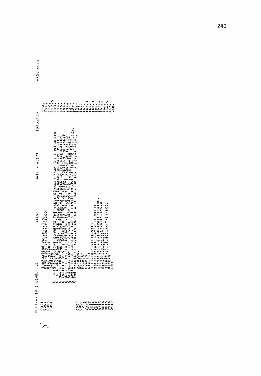
240
o <
-t - 4 M lA
0 - « N ^ J " ^ T A 0-^r: T - O - i . M - T O f f - \ A A O Or-a . A A ^ A . A . A . A A , ' ^ r f ^ A ^ . ' ^ 0 0 0 • 0 0 • 0 • 0 O-OO O 3 O O
. 1 N tr\
r -r -^H •J 9
II
JJ r"
< •3
UJ
> _ i 4
•>
t - l
'— O O
—IM •Z-t
— K >
— » > — — O •JJO ^ ( M _l —
< — >< — > o •JJ o
. JJ a: «g UJ 1 UJ *^ • -i-£z>a 1 - i - j _ I O O _ l K — — > O U - P - K l / l l j - l a C ' 3 f K > . U Z < < — • u < T O " — > z a j u j - « o ^ O t ) l K 3-• J J J O K U J O <
> J u._;i— JJ JJ _ l < z o — z r t J D r j - >
K > —,- . XT ^ l U K Z -1
X Z X — - D • K < " ) 0 K ; / 1 0 ' J J at O X > u . a : u. " ^ z a . < _ / : 3 3
u -« .* u. CS/1 - J U J > K z o < K za. < i l ' j J D — J i r J O r i / i K z r T 1 T i - O D O — K X ^ U O M < u . < 3 O «/l l/> <
Z — J J < i y o a j X JUD I O K > — < K U J T t —JJ - » » - • > . ^ o z Q i : < < K < * — J J > - I Z O K \ L I
" 3 0 Z a UJOl / ) - J 0 4 4 I _ l < i/) _ j :)t J K <JJ*^»- iQ</ )
O c t X JJO <^ > U J V Z K u j u j r a c - t < ot rxujo-3>-UJ —KWOKVO >
> o</» -o T . . < ~ D LIK- » O J J ^ O K .- Z •> o K ^ u i o ' x < a :
< 0 ' 0 ' < K • u i a t < u j y i > Z io u r z < • 1 "«'JJ-^ X K O
Z Z < M K K 0 I K O U . »-iO ^^ K - < — I
• 0 _ < K > o o ofrtlu^ . Z ' U (
D ^ X u i o C S U . Z < 3 J ' / ) ( O z 1 O T S i / I O O i - i uj< o t j j _ i u j D . / > a f » D D ' 2 ) X < K t < 0 < U . Q ' J J O K _ l
o — O O • -^.-4 . O K PI O O — —I I 30 < — — II > • M — I K •» —
— — K •» K < — K
>< — K > — > r > • O O K . 11 <<0 • —1> —ts—o-«o K • • • > a 3 — K K # » 0 - 0 - l > K > — « . X - l — < — • . — > — > —
. II • <> < — ( < I O — K K II
l / )QQf« _ . ' ^ • " t O K - J I UJ T Z i / l _ l i / ) o t U J K O < Z — U J U X
K X M ' K a C ^ K
O O O O O O O O
of i - . N f ' l ^ l A o r - O J J - O —rJ<»l•*^A•0^-K o o o o o o o O O ' - — ^ « - t ' < , - i _ i — ct nooo ooooooooooooo o oooo ooooooooooooo u.

241
o i
o • (
0.
• 0 - l - V j > J I J - A O K X > - . - < - l - . V J ^ , f ^ ^ p . ^ ; y ,
o
A N, •O
- . i -»r> j x i N .1 M.-N-vrvi xj M,M,A(IM.->J ^ ' M ^ fM-N N r g ^ r y j l M , ^ - • J -J M ^ fSI .Mfsl g r s / N fM "J-NJ M M - . | r \ J . \ i - J J , J N CM <| M- .J N-NJ-M ."•J "NJ
O > => "
1" _l 4J JJ >
5 - ^ ^ U . O — ^ 1
2 : K '-U -0 or- — JJ ar x>- I- x ^ _ i D Z K i o r o u .< a i - i O i l 'X ^r-^-r:-< . K — D - i T o j ••./I a
r- O a i x UJ _3^ < > - K ; U O X r- ^ Q ^ . </i £ . z _ i i:y) >y) D -< < . u i < j > — rr . ^ ^ Q _ ^ •' - > • ) — ! o '. r ^ • > < < 4 : u . T , -o O O J _ ) ; N Y Z J J X O < O - < a
II r- — _l V u rrpuj a . O - Q i O Z <.y)i/) .—. o I o o t z o. K x d r
•u — T - i i / 1 ^ 0 p- K • -1 < I U - U J O r- K -t < : i r> Q II -It K I . O ar t » > < u r — 1/1 t J 3 a : j J 2 K - M y ) X
O Dt O z Q 2 K O - E — — <Z-l 3 •? - > ; - i L U ^ K -1 z V, 3 3 K UJUJ 0. o o 3 a . _ i r o UJ - n i - i u. z—iujQxz ^ — - < O L I - : J I : ^ I U . I — Q t o < i — » < j j i < 0 a j , u j j > / 1 2 o t - l u < r a t ~ — .tl
T t o r z O o t K at - I 3 J J I m o x - yi — OL ?"Z t / i K O z - i < Q. UI r — U J D V O K O < aj U.
"—' •-< " I D Tt »J ^ K N l/)|—• K ' < ) I 'U Q. "s o - • v O Q . o . O Q t - i J j o > - < 0 3 o r u. Q. Z— • UJ3UJUJ iJ _ J l O K XUJ 33 r S, I — O ' U Z Z O o t JJ Z < K K 33 UJ IUJ Q O liJ Q. <N •o z—u 'i. a X z o K i u i T T t z • — 4
ZfNi p - i _ i a . T > - >-i u-^-i o lu K X « « U - -< • —— X O — - I J J O i - U J K i U O K — » J K _J IN r « a. —— - u j Q — < I < £D K — a . z • » Q I • fsi •'•' -^ X I - J K D rS^J— • K O — X —JJ UJ i o i / l - t y z a j h - x - r < :7 K u o ot < o o o o D t ./i a x * X I » 0 • / > O X _ J i : J i ) y j a ) - i J _ J « j t O < » * « Q Z — 4 U - - H - K 1-1 UJ UJ 1-1 > U J < D U . X ' / 1 X — O . N
- • » l o r - . j z . o o i K ' ^ . N z ^ T > i i D < a . — o x O < \ I I - M i—Z a. i z u i X tn Z K < < a f -^ O-D — z O Q j t JJ T.^— —— - ^ — O — 2 — H — I X J J a O l A O O Z U l U - X '.i S. # • rsiv X — O r s i O . _ I Z _ J O O U . K > * r- —-i-Jt • x O ' - i 0 - i » — i • O - ^ V —"v K UJ O Tt-^ (.J O • -^K D ^ I O i X U J U K ^ K O » l N IM— < \ga j (_^ - r -^ UJ 2- iJUj Z « / i o u j < . ^ ^ Z O - t o I — • — o f _ I O — X — — l U J J r - O O O i r D > L j — — : 3 t : u J < D D i / ) 0 .1/1 D J ^ — • X l O — K i / J O Z O c c UJ UI ujQJ-^uj — < K X - I K . X I "H/I Z i J ( M X eO . r — o(M - l a o z o t . 3 : « K - i j £ ^ i / ) i - u . . < z — x o o \ » — — . . —
—> Q u - a . _ i i i j < z i - i o ^ Q t i j i k / ) o O u j » m > j j - » Qi/1 —•<a — » - < — 0 0 1 JJ— o j J i i — . 3 I N U J X — i j j i j j (>o*<M'-< J i/> t-i i/i K * O' lof o r r * Z o t K Z K > K O C D D ^ U l X l Q f l 1A» X X N J - -5Z1t —X lA UJ < o . O X * — Q « — O l M — r C Z o o < r \ ; a J X X — - I K K iA — i ' * v « > Z o u j O'^ iA <M lA a o — r j f i o z tN « — o w o . n — X O — ' O t — o < i x i D u j — o o i _j|—•JJO JJ (MO •J ' ^ x : i » ' - < o > o a t i . . • .fsj . 0 0 0 0 0 0 0 — K K i Q - . K n i - — u ) o x U J l / 1 — - I K a t X i / l — 10 O Z r u . — 0 0 — Z ^ 3 - 1 p-lOu. r - O O O • . l A i A - J X X W - l - i K - l o f l l / i r / _ J » . r t I •» O i^zt— < < K Q - I I otQ2uJcr ' ' -<»-Om . .11— u-Ootuj - O J O - ^ I A ^ O ^ A . •o i />o —rj(»i o c . o — t o . lAO—— 'T t_JUjU<LU—<:! ~ ~ ~ " • - • — — — - - • — - . . _ . _
• - I f f ) . •J On
:3X U J l / 1 — - I K a t X i / l — 10 O Z r u . — 0 0 — Z ^ 3 - 1 p-iOu. r - O O O • . u - v i A - I X X W - l - i K - l o f l l / i r / _ J » . r t I •» D i^Zt— < < K Q - I I o t Q 2 u J c r ' ' - < » - O m . . 1 1 — u - O o t u j - o i O - ^ I A •o •A . • o i / > o —rj (» i o c . o — t o . l A O — — i t_ i UJ u<Li j—1:1 l x i » — o t u j o II r o i o - Z M - i < o . a o i N — — — r s i c o r - — i z i r x i o o o o n o 11 o . i / i i i o D < K X O X O t O i / 5 . ' :>_/" IX K O U - Z • < I I Z I I —cn-J-IUJl/ l i lJ . II II II 11 11 11 II 11 JJ II ll II II X K O O — II — O—1— II 11 I^JO Diu Z ^ ^ O K O . K I - < O L U O II •'IJ O n i o n II K — — a . o O O a t Z r Y r o o O — — I N C V I ' ' . • ' i r > ' - : ' - - r j ' ' ' i > - a j H I L - H O n i j a fvi -1 3 n ' l . T ' i ^ O — l - ) f j i ) n o r g T ^ J ' ^ - n n c u i a a - U - i / P U l L i / P 0 0 O I O X 0 1 0 J < ' ^ t - o t / > ^ o u j O ' - P c r ' ' / > 0 0 — t < Q r u 1 Q
X n " - 1 — K O - < > — — U J 0 I . / U " i / i i x U J K X Z - J UJ JJ UJoO_lr i^ - U U J K < 0 i/> p-p X — a — u j K X x z i ^ < n Q- X X —/'puot K K K O ^ K P - — K < - t a u. K i — I — r u .
oooooo -J oooooo o oooooo
at '^^r•^ rry.f tn -O p-ooO^O'^ " J r O > » i A O h - U O O —rsjf^-^ vA • O K 3D C^O' - fMl< l , r in K O O O O O O 0 0 0 » ^ H » - i 1-1 ' ^ , ^ . - • ' . • - 1 — • - - r J r g n j r g r s j ' ^ j r / ' M r g l^Jf<^'<^^•<^mmf<^ i ' O O C O O o o o o o O O O O O O ' . 0 0 O O O O - , - > ^ - ^ r - | - l O ' - : ' : - 0 0 o O O O O o o O O O O O o O O O O O O O O o o o o O O O O O O O o O O O
r

242
N J
J t
a.
—* -^nj<| o
•A Or».Oi». -.OJ.'-. .J-A-0K^».T3 3a5> O-llA O K ^ O O -< N / I - * | ' A . A J > O O O ^ 0 O O O OOO^OOOOf~"~Kf«'Nf*OOXMCO (MN'-IAI JAJpNjIN •giM-.jr.t.-^J'MM'M'MrM^.N MfMPXJAj W "-JINl N.">J
O
>. fO lA • >.. O
o :3
z H . O
O o JJ Z JJ K O iA < — o 3 — U. ^
O. y) a; U . — JJ V K a. UJ u. I rn <
< K UI — z • : — m J- . _j
—</i N o X I N * 1-1 UJ U. a. I . AJ • rg J — I m
UJ — . I d -o X .- 1V o** —
i ^ O » rO I — o t
O —P^J*
w
z 1 - 1
If n-r UJ . . K S O O < — ( M
m 1 1 I II O 3 U . U . Q J J II JJ . .
O U . O O
Ul V K U.
z 1 - 1
4 0 0 - 1 I I
— O K
. z — — o o o o _ i
a
5 IA p-l — _ l K
UJ <
o > O K 1 _»0 II U J _ I 0 _ ( > ouj<*> :z — > — U J -
—k
K
> at .^ • — K Z K O
Z o
•At Org —X O — X * — » • < _ AJAJOI fOu. — : N O O Q — _ i — • — —p-<
A l o O X * «AOO . . o u . — O U J .o_iJJQf 11 II Q Q * — O m O D UJKcn • - i K O > — . O X X - ~ X—Q • . IA—XO-* . V _ l O N , K • — — V - l K MK II —O II — II 'HK .1——yjfMKK . .li.</>0-J^/)< .—I— —• lM-~ + »-. 0 _ l « a t | • • o o — Z Z * O U J C C D O M .—VI—K — K - i Z Q .AJO—pgO . o — X O . I <QOO-«- —•••—O'*' —•••« II a < C / 1 l l o n O O K K II K O H I I K Q K K a f K K O C K O
t v — I I M < < \ O f < 1 — - t — l _ J — l l < r g — _ 2 — Z — K Q Ou-rApAo i lO'J.-UUlxujuju.ooQu.u. _!-< at OO Of o - I IxiZ O—<of i ' lQQi - i>—1- .>> — Q O K — — O * X —OXi-iOof UJ
K UJ UJ -^ I X - I K O K O lA O
' H .-« (M
O
Z •< ot O f ~ ' J O < > O r - i A J ( « » - r ^ O K C D O - O ' H l N l f r i ^ I A O K . B O O . M K r1 ' *^(<MO • r • * • ! ' f • » • • * • * **•>»• s J - l A l A i A I A l A l A l A l A l A l A o o -< O O O O O O O ' . ^ '" o o COOr..-10P3 OOC o o o f . o O o o o o o o o o o o o O O O C . O C O O O O O O O O O
• o

243
.A . ^ N N n .•f4
w.-« • g » < r A O " » « < > 0 ' < " g - « 1 * A O K 3 3 0 O O . » ' > » ' O — A I - O ^ T A O O o O O J O O O O o - H ' ^ ' H ^ - * - « — . — — — - . — — ' H - H i - i i N A i ' v ^ ' g ^ p g
V
M
UJ .XJ 33 J X ^ z
JJ < — Z — D J 3 . 1 -J —
•n z K« J. o o ~ 4 u o K > 0 -J UJ J -• xr<>-c;< J- >^z N r — J Z - t - I z o — ; o - J Z X I Z — >-
X . X J _ I 3 0 . V j t Pi X a.— -I X o -J—
XlO 3-H AJr— . X Q . -M a . O Z X T X Z T f K K Z'U • — _ J — O — — O -1 ujJt -< < -.J Z.n yi^-> V ^ 3 f < — I 3 — X - I - O - P Y J ^ O — Y — —
— 0 4 — 0 .J - u J D > •— • • Y Z K Z a . O - I J t O O -p — f l
> . i j f — Y — 0 0 . ^ 0 < • » • — O ' O _ ; — l I u O - — a c Y ^ x i - . r H — • > o • •4 3 O u X ' - i- UJO 0 0 II K O < —
— - j j Y i O t . x a o - •<—o z.» 3 0 0 4 0 - » J _ I K X X O > 0 — 0 - 0 . r _ i O D O o K > o > M . — K
O— X - - ' U . X O Y 0 0 — • « — 0 1 — > v ' > » - i r u . o — >— K uji/1 . > — M Z N .
4 X . . ^ I Z ~ JJ -^ot o I • — Q — xi > 0 3 - 1 — U J o O O i / ) X — u . — 1 - — • • .
, . — — —OJJ —O O i - i - -JK UJK—•»—O—C •^ «/l JJ . i X X — "NO UJ _ J — O K * «'>'»-00 a. — ^ Q I V O P - X 4 O — a > - X X . > > — — O K — • X - J J — 4 X o - Z U ^ 4 z - r < ! £ ' £ > - • - : ' ' < = ' C x O i - 1 - I O X O X P M O - " ••Lt —O K » > > * ' » 0 — H O — Z 0 2 X O Z O — > K 4 K— —.« — 4 — U J > 0 —
^ f - O o j o i - 4 Z O -o:». - 1 1 > > • > K K 4 K O Z K ar x ^ o u - o > x a . I > — . j o — — > — K o z o ^ j j — ^ - 1 > - X K l u i ut- 9 t » o . o * i > — — - i ^ - O X JJW0O4 - T O K X — o — ^ o > — o — > — O O — c Z J Z O O Q >-•— K O ' K . ' i ^ ^ • ~ • : . ^ a . o i _ J ^ a t O K O I ot — > . — K K Z K — 0 0 r—3-0 OOZ—-•-wo-I o » 0 4 o o o o o — 1 0 . O O . x u - O ^ »o—or4 O— > z o > • .—o——o O S U O - I Y J J U ' X O O - X Z - I N 4 3 - ' ^ - " " ^ • - J J
2 _IC:*^i/<CZ —> O <x> >p-' . > —— — 4—KK
2 — < i o x :»./» - t - z x i / ) 0(*^ 'H'H o — K K « o > « «
- 2 ^ ; i ' ^ r z O Q o r S K - i - o noy - • o . » - v > o v j
O i - — X o o . 0 4 • J Z > - a t — 3 Q * • " O 4 « > 0 — f'' a O C X X X a > _ J U X 4 K M _ l k ^ U J K K K I ^ > 0 > > 4 — 0 > > 0 a-y, K - i K i / ) I < K r _ i z o - t > ' « J H — — 4 — > ~ ' ~ ? ~ " ' * ~ 7 ~ - v x i - r 4 - O Y x Z — J J O O O O - O x a . > u 4 X X O M - U . U . y i o X - ^ i X Z XI a ' — a Q O K i j . 4 X K — O — > — ' < u j > — < - •
K Q UJZ oruj
- * I—0^— 1 I m i ^ O t O - ' K i l I a : UJUJ u j u » -K U . - J O ^ J J — < I X X f a .
0 4 J U j O r - _ l K K K K O
'.J^'^'JiJ^l.f-J <~>^ 0 0 0
z 4 ^ ^ . Al . * l ^ lA OKaxj-O—Airo *iAOf-a>0-0
K O r^ Z, OC O C
- o 0 0 0 o
0 0 0 O o t . 0 0 — — — ^ ' ^ ' ^ . •HPSi
O O o < - D O O O O O ' J O C O O
0 0 OC-oooo o o o o o o o
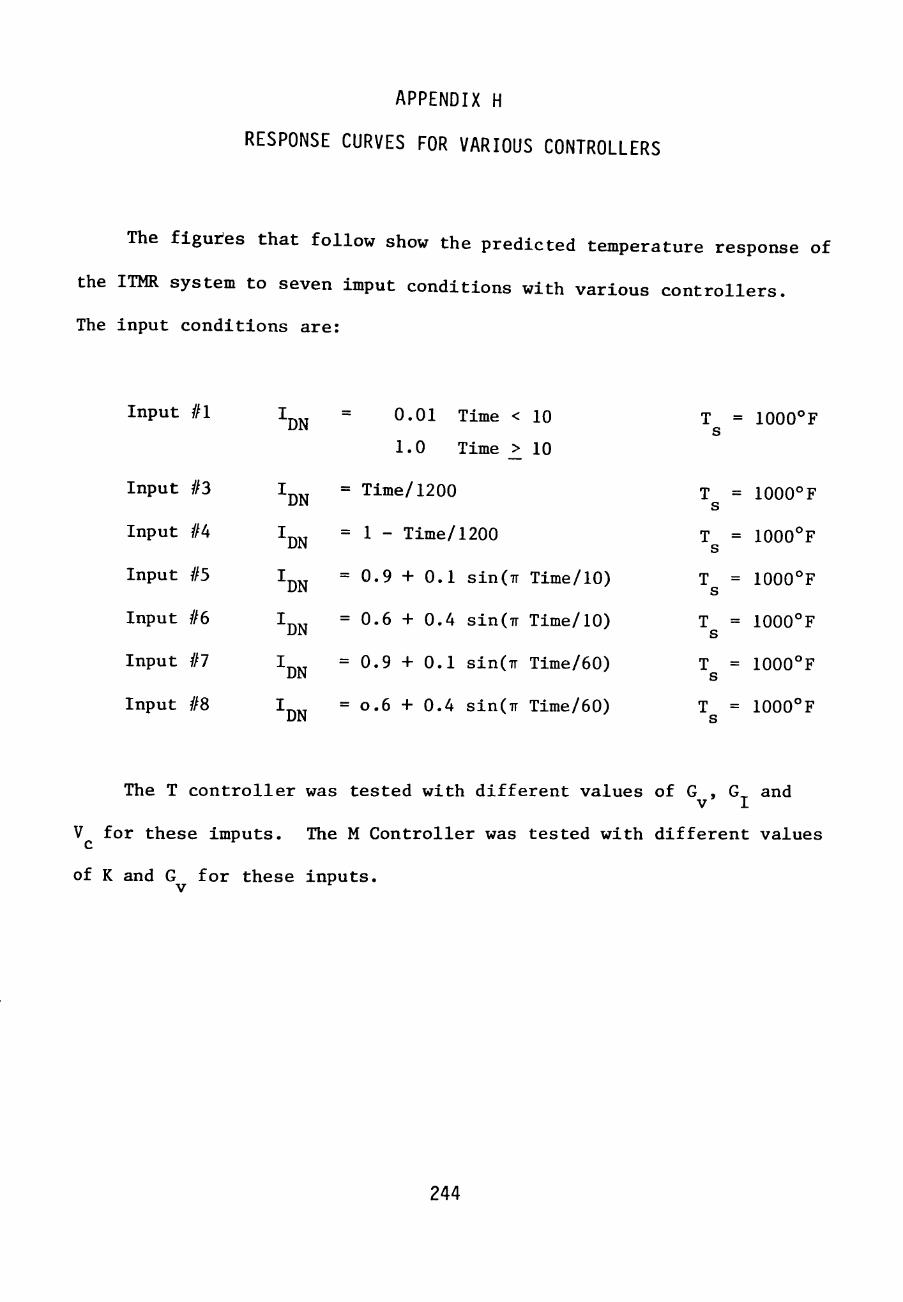
APPENDIX H
RESPONSE CURVES FOR VARIOUS CONTROLLERS
The figutes that follow show the predicted temperature response of
the ITMR system to seven imput conditions with various controllers.
The input conditions are:
Input #1
Input #3
Input #4
Input #5
Input #6
Input #7
Input #8
DN
'DN
"DN
"DN
"DN
"DN
"DN
0.01 Time < 10
1.0 Time >_ 10
= Time/1200
= 1 - Time/1200
= 0.9 + 0.1 sin(7r Time/10)
= 0.6 + 0.4 sin(Tr Time/10)
= 0.9 + 0.1 sin(7T Time/60)
= 0.6 + 0.4 sin(TT Time/60)
T = 1000°F
T = 1000°F
T =
T =
T =
T =
T =
1000°F
1000°F
1000°F
1000°F
1000°F
The T controller was tested with different values of G , G^ and V I
V for these imputs. The M Controller was tested with different values
of K and G for these inputs.
244

245


247 • I I I
•—* • t T
—1—1—r— t 1 4
- ;— »--T-r-4-
f - U -. . . 1 -
h-"H
- -.-p-i ! !
- • • •
- , - ^
xxS^
i ^ • r t -; -
t 1—i
1 u at
•V -f -
-J—1
-I— tf ti'4^
"tl L4-X
••v\
;)tt 1 . Ji
IT —1—[4
t •
"' i~ " '
^f ' 1
> i 1 » — 1 — 1 _ _
. 1, 4 . ,-_-_z .. : 1 ' ] t — iLTasD (r_. i : • 4 -H M • - f - j 4 - -.-J-- - - - Gv = C . i i - u }
\ '.-I • '-I i J l - - - " " ^ ^ .
•4--- •>----( 4 - *-* - 1-- - / \ i 1 • i ' X —
_-^J-U . - -1-• l—i ^ 1 7 '^' ^ J 1 I __ T ^ t - i - r - - - r 4 - J - - 1 - ; - - • • ! , / ^
- _p _ . ..
1 v.^^Bjjt^'^^:.: ; T ~::~: I 1
1
"hZ\ #^======"==::::±::=-=—^ - '4^^-114-.4 4 - 4 1 , 1 •4,' _ T 7 ''< --^r-.,..!-..
X:-:4J--.;X|::t::i-|::v.rX| _ _»_^ I I .. ^ ; . 4- U -_J_-4==' 1 i i / _ . _ . _ ^ , j 1 ^i^-4—t~T 1 t ^ * i 4— " ' ""
^ - 1 - - Jr^ • - - ' • - I t -t '^ \ 1 1 * : \y'\ 1 1 \ ' ' ' _ t i L " '—1 "^
y^ ^ j i ' ^ ^ ' j p _] 1 ! I /<T^-rr5--I .|--- -(|--| [I 4" - • I-—
i ' ' M t • ' I i t . . . - - - - J -
.^JIiii"lLT i 1 - " ' • • - i M / , r a l ^ o . l - - ^ • j ^ l ^ c L ' -
" T l T ' " ~\^^'-riK^ 'i\ri-\ L^ 4 \ ^ - - - - L . ^ - . i - ^ ^ J - . J
- - ^ ^ ^ ~ n £ f 5 x r i " x - -
1
]
. .-- .
CSS f O i > ' " « • *
ITT T C<:>r:v^pFK'^r'^ . ,. -t t 1 ] ; ^ ^ 1 1
|Hi'~"'t iiuir"! -.-- -i-11 ~i 1 [ i l l < . - I P X . , . 1 ""•" _ - - v .
1— <i^''£n ^ _^_ ^-'''\e^ \
<;,,: ^>.P;^ / ' ' >
_.Sr : ^ L J Z ' V ' ' \
44 f"^^" ' r • "x:>/'VJ''"^XJ' " ^ ^ i ^ ' ^ ' v - > - "
-+ + + - 2 ^ Jt-^—=-= '• ^ Ix t If " '^^pi.£ ^~'~i>+;-h "^rr- +4-1 ^ - ft
-p ^* -^ - i - -p "XXX- -ft ^ " X ~ - j - -(--t- - - -L-j -•(- - T-f-t- - - - - - ^ -
XXX 1 j j — n • I t t 1 7 - | ^ 1 - - • 1 -(-* J- ^ I ^ ^ T Y " ^ " " i . .. - ^ --- -• . -
j • i ' 1 1 {^-T? \ t 1 1 ' ' I - M p>*~ ' ' L • ' L / ' ' ' ^ — ' ' ! 4 _,
' 1 j ' ^ ^ ' l ~A ' 1 1 4!4--*' • ' I 1
-].-[ 1111 \\\-\t -ttii-t-H]-[IT"HMM 11 MThH'' \'W'\ 11111111111H1 Hitl i 'H'H^^^ "t I 1 '" " T r ' " \'' ' ' . . I X X I •1—4-4 '— — 1 - 4 ' —f-4—• -t—»-- *- - - - - - - ' ]
1 _|^ 4-- -f—../n.t4 J 4 ^r> - - -Xn-- .n^- - , _ 7 ' V ' j r t n f " ' t l IX M f ' - i t - t* ' "' ' — I " " X x " --4-iX--t-4 • U4 • *^ M ' M M ! ~ " • ' ^TMl i i t 1 M l vM ^^\y) 4 -t • M
:=Xt|iiXi Hi X ^ ^ i ^ M -r—1—^1-! -r-t - '^M"! " t l 'T l \\ 1 ' ^ ' . 1 M I I M

1
- -
n^ t
1
4
Xtt;|_^----"+-t--^- ^ "-' "^H;i^"[ |1 '^ T-_T- •-H.T-TT :T: _TT ' ' ^ : , 1 " " - • ,
T - t - f - ^ r ' " " ' z—-^=v.^--,<^ --^-^ . - - -f-! i / • .y
_ _ i _ X '" " .-'"^^ ^ ^ "25-Oj_2 [ j i r f l • , . ' ' ' / — 1 ' 1 ' jp ' /
1 | l i l * ; ^ . • . ^
M l ! ' ' ' ' [ i ! _ L L -4- • • i V • / ' 4^ /:^ ' y:"V ' y^' "^^ ^ =
I X '' ' ' / / ^ / X -< \ ^ . ,-= . . C'l 1 1 f ^ ^ ^ / ^ ^ ^ - - u X ' -X ^ ^ ^ ^ ^ - . - _._ ^^]^4X ' 1 ^ l^T - • -'- ^ '-;'^ — ^ X - / i , « i c ' ! V j j • - » ' . . "tj J - 'r T M r ' 1 ^ ' j _ 1
' M ' • • ' ' i I y Zt6d. - - -M ' V ^ - ^ " X ^ p ! ; ' V ' 1 " ' - ^ "" ' 1 * I ' 1 1
M vii ! : 1M ' • "G /4 i ^ . ^ - ^ - t -
-f-
4
[ ' ' ' i 1 ! i ' ' 4 1 ' ! ; ! " L " " " j b / M r - E i - _ . , . _ • . . . -l-l r- +--H - 1- - - - - ^ J j i 1=X - - - •
' . ; l i p —t— —
-: H*<*-r-H—H f ^ X ^ T =i i- -—r--!--_j_; - j r i 'T, "" " " • "" """"i 4^ iX 1 - - • - -'
" T 1 4 i i I i j ' 1 tX i X ~ — — •
- r - » - - r - - 4 -•••--» f^ "'' • • • ] • - 1 . . . 1 . -4 t 1 ! - - -- M - t • ' M " M - - • - - - ^
-T—-1—ip-p t . • 1 , - M 1 \\' ! i IJ 4,^' " " ~ T ^ " ' T i r ; ' I B » * ^-^
1111111M11111111111 lfcttfflfiii]JL-lJ4i 11111 ITlTi 1111111111 Mimii 11 :fc4l^^|f |t| j||4||4| ^^A -ffl-J1'fflt 1111111111! 11111 mfflffli]

249 _t|-- } - - I -4-- t -X-- X- • " r x x
- --'--f - -I- j - r - - j - - . - - - _ ,- . . . 1
-^^•1 ffl r ^ + I H +14414114 H I I I 1J L J ' M ll ll 111111111111111111111111 "" T'HffHix H"hf 4"f1T-fflWi#l4ml4l144IJ4411111111111111111111111 , ; _L_ (•.,:tK<tL ' " 'T "
- ^ -T^- T - - - X - - ^ _.- thtui-^^_^X: -;__ I . _-; - ^ r- -TT -~T~--T7^"^~-"-"="=""=~""~--n-T±ttx :"": : : - -" : - : : :" - --t------ - 1 X / i • 4 y4_. „ ^ -, 1 XX 4
""Mil XtiWfflHiWfl^ mMHi - 'WIwH i dwIHtHi -tt?:::rXTyX5;;X:cXX- 'X.v^^^MI XXX. ;X--=~ -r-T—-.^ »-t- -Hf^tir"*' f^X'-1 ^•.•- \ - -/- - - t T - M t-t-t - ~ - - —
' I I 1 • * • • 'T '" ' . ' * ' • / ; " '• -'' •'•• 1—p-l (—
—, i . w -L i 4 .,^ fcV _ I J l i e ' ' ^ . - . - . - . . . .
• 1 ' 1 r t- X- . . . - - . . . . \]^ _ , _ ^ _ . .-. , X - ^ - . - - J - 4 - — • •" _ __ T i l t : ' 4 - 4 . X "1 ! ' ^
1 " ^ M i -1 " T"""*" M ; M 1 "" T r ^ j T " ' • " "
' 1 , 1 1 1 .. _ j _
.X M 1 •' 1 ' 1 -ifL mm -«a « a ^^ ^ ^ ''»<&---
, ; 1 , _ i _ - Xil^Ti. Aj.tC\ _L -
' ' ! ] ! _ ' '^ .ornNTSA c_'' n , X -"t""'!! " " - - - - - ,
; T X - . . - - i - i - ^ : • ^ , . .
_' ~l^ t t \_ " 1 - - - . . - - - . . _ _ . • - — 1 t ^ ^ " - * ' * ^
1 ! i _, X _ ^ ,^ j ^ : a3£. - - - ' I 1 , ;? " v 1 1 1 . , j . ^ ..., /^^^.. X ^'j^'^jcr ' " s " - - -- 1 1 ' yi/Lc^ > iv S
j -5^ -f 4- i _4 T j ; / \ ' ^ ' ^ V • X-I ' U . I I f I- / / ^ ^ ' , c - ' St. L~. ' ^ ^ ^*> 1 —1 ^ ^ ^ ^
, ^ 1 1 t f * / X ,, A X " " ' ^ ^...-••-•5..-p«--«i*---i = , ;4»^-"*"«S^* 'B»^-*« "'•'• ' "S" M / ' - C ^ '• ' •' 1
1 p , 1 1 t ^ i j | i i D i l 0
M 5 r" \ / / M %\ M / / M ! ^ ^ K h ' / 1 ' I ' • ' 1 ' T P , ' : 1 ! [ I 1 y i
1 ) 1 / • ' ' ' M .* / I 1
I 1 4. * ' I ' 1 1
' 1 > 1 t
M j j t ' ' " .- .„ • 1 1 — » — - ^ • 1 I — — -t— — =3 — T ' ) 1 1 1 1 - ; ; ? " ' " • " " ~ ~ a : : y *" ~ " t * T 3 1 1~
1 j ,» / u >i>c . -yn .*'?| —j— _42ai s * ><k- _ ^ ' M i - jhtlL li>-:z:\ jlltl-.X, - - . t i -' ' ' ' 4 . • • • • • - • - — 1 - - 1
; M 1 • - . _ , . , - 1 ^^'Z—^ 7 H^ - t^ i r f - * • • . - . / /Ur - - - -1 • • ' ' t 1 ^•Xo'^Tf\oi\f^ .4X4- .- —- -- . ' — — 1 -^^-- '- - ^' M T r t r t ^ ^ + ^ ^ J . X: .-

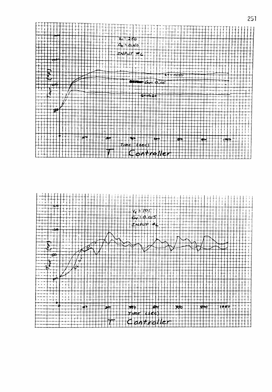

• ? 1 • r -4 -
- 4 - , -
1 ! —r T - t
-r+-r-rx - ^ P 4
i
' 1 1
—^-r — - t — • . — . —
-XXX : k _
- ^ ' • H t ' - ' ! ! : 1
; ' 1 • 1
: 1 I i
1 1
' ' 1 1
t i l 1 t 4 t
1 M^ 4 - . ^ 4 -
1 ^
-1
:
-pi
?
- 4 [ -—1 h-
m ' ! I 4 -1 t -
B * 1 1
-fxxr' xx ^ I ! |
K r
1——1-4.- -U
isrl -If I-
\ - —
-44x--r-; i ! 1
' 1 T4 1 ;
4imi[lJj4[iUJM4Jllili1 ---. -. 4-
- T — T
wM^MIiffi 1-4?r--- ^-r?v.4gli- - ---4-i j--- " - / - ! l^.^'X",-. ^ TT^s~'A'/'--v;~~4-=----='©"
K- .---fC<X-1 ' 1 4 XX T^f-^ai-
^•'P-^44:^===-:=i=-^^-:|t.-4bs-=i: ^4^-t—t—-=- 3td.S. p-X-[.! „ii- -l_.x '~-s^'y.fur_^u.:':~:. r-\ f-T-i—(-44- 4 -
; 1 I , i 7"!"
1 M ' 1 1 i 1 1 1 _|— -._— —-.__..___ .|. 1|_ . t 1 7'^ ' •• J?" 4ir" < ) ^ " •
! [ . 7 1
X i y ^ ' ' " ' ' ^ ' ''•i^Y ' ' • ' ' ——' ^ , ^ 1
252
- _-. - - ' . . i " ' -]Jw»-»•-- - -~T-4T===-| - | I Xj
- xp .-.- |.:[. ---. 1 1 11 1 1 X-' n
XL T xrti _- . . X
1 4 — 1 — 1
4 . --.4
—4 ]
a * '49?' - ^9^ ' - -
_^- ^X - ^ ' ' m^Cj'i''riO/ttii'' 1 -— -M - ^ -. : ! M 1 , . . ! I J-

Htt+r I I I I I I f
1_4— ;. 1 I • ' • 1 '
T^TM-! I • ' '. !
-rrt-44^ . 1 ' - ^ 1 ^ - - '
4- . -1 U , -1 MX T-M M V , ;
' ' ' % / t ' ' ' ! ' ! 1 t ; 1 r '*• T ' -
' ' 1 1 1 1
—^-44'-^ _x.-i-4.i*r
' ' • M ' M l - • - 4 - 1 1 *•
.rxrrt-! 1 1 ' - ' - ^ r - i
! . ; I ^ T - ^ ' -
©S4-i-'-"1—41411 If jjl j ji4i#tf [tl^itt^ (lliiil Xxjxr , -j: - J i iS?~-" f l irX4:Tt-t + ::'M - _ r' ___Ji.5;ivc>: Mr^ :M i--:-4
M l M ' J ^.m iMlk J: T . I f 7.17^ ^ 1 J ^ t 1 j j j t ~^^^ - ^ ^ ( j ^ | C t -E - iLA'^^'-^ ^-^ - - - - -
'-V -1 4 X 4—X / " V /'' ^ ^ ' ' 1 4 _
' \ i / ' > Pp. \ S. ^ - ^ ^ ' ' 1 y 1 j \ X y ' ^ > >* '" ' \ y ^ " ^ -^ -^ - ^ - ^ ,<i-*:i <:^*rf ' ' '
. \ / / y ^^i^ .^-^^^^'^ ' . * - ^ s ?- -.>45^ ^^'^x^- _. t /" ly r ^-""^ ' N^*;/> ~ 1 ^J
r-lA'l^^-/---"-'--"^--="'~'^^--=-'^ 1 M L / .' - ' -
! /yT y~7/ t ^ / _l 'Y I / 1
/] \ 1
X'l • Xz^} • ^ ' M l ••
M ' ' ( ' ' ' ' M t ' ' ' ' ! ;
_,—1—1 J—p-(
, M ! 1 1 . « » " *<»i - iS'-- - -t»* j s i . » « | loa
r - - • 4 . - . .
• ^ ^ 4 - -.. .. __ -.- . --. 1 • • t " t ' " . • • 1 1,1 . , , - - . - - - .
"""4;::£E:E:t£±iX-=i'^^E41';i::::::i:::::;:::i:-:.;--J

-p-j—r-n- :
! 1 ' ' ^ ' •
I I t "' " •" • - - - - - • - - - ^ ^ ^ : j ^
11 r i i ''• "" " " ' - -1 i g ^ , .. , |.,..
X1M-[MM,M. | -:I.M:M_ II ^^s,i=.^y^^74= .:
-r-^---U1- \M - i T ' ITi""/ Y /
' ' ' 1 ' jA y _/t \ / 1 / \ /! L
rttir- iX^^iX-n-X-AX/"X'X-^--444-;|_+ ^/\ A / - - M Jc7«i^-/ Ky
"^" 4 1 l l : 1
-•—'—X M ' i t 4 XTrT^tXlt .]- I- - - II--1 J_---p 1 1—H*-' 1 p 1 — — -1 - f - - " T " ' — . "
; . i : M ' » - M t 4 < * t •"* ^ 4r**^ • • • i - x i t x x i ^ i ••• 1 , r ^ i ^ - --|--^|-l-r-l- -r-M——4-T"__.. .. . _ 4 - 4 4 ^ 4 1 1 ' M I M i \ \\ 1 J.- -X- 4i 4- - i i^ /*+W . . 1 | 4 - | .,. -1 + t- -M t- / 1 - ' - ' V ' / J T i ' ^
—I—1—1—I—1—I—I—I—f—I—x~\—1—1—r~i—I—1—7—I—1—I—I—7—1—I—T—I—\—r~i—V
i r o - ^ ^ XLS' r «=(_ . . " • '4
' / \ y v -t\ j \ f l v J Z.\ t
\ / \ 1 \ / \ i \ / I', --/ \ z X Ti -\ \ ^ \ ^ \ y J
_j , 1 _ 1 11
--/^ ' MT. / \ "T/s::.: ;- -.it:: ' / \ > / \ -* --^ / \ ' / \ J X J J -1 J. \ , . - 4 l 4 l
7 ' % t t V - A - 4 t 4 4 I ^ '^ J ^ 1 \ - -itir _ ^7' - 12 X^ 1\\.X^
1 K4-I-
1 I i ____4-"—4= 4-4- 4- l t -4?" \^ f ><> i*i«^ --^-- - 1 * £ - : 4 I I I 1 4 •• : M M t ! _ ^ 1-4-1-T i t -- •--. .il
I l / i . .p 4 O f / ^ f ^ - .- . . . ->-• 1

1 ' '
' ' ' f • t
1 ' 1
' ! 1 ! 1 !
'
[
T T - -' '
* -T4-
1 i»<-4 -r t-
- t 4 — r — r > 1 4 ^ ! IH. M
' K- t
-r*r
1 • : • I—-r
j ' ''Y — • • M p 1
^44X1 —t—.—r—•—•—r—•—
XXTX iXt--xrrrttt —.— f ~ ^
p
M i l '" 1 1 j 1 ' '
' 1 — — — t —
]lj~\] • ' ' ••-
p-4 4 ^ 4 ^ t-b---^—-< 1 ; j?t -_. .^- .^"- - . . . i - - .
i ^X . :4> f i , ^^^x - : : : x : xx : T i T jr/l ^ ^ ^ \ u ^ ' ) / ^ ^ ' •'• ~ ~ '
'{I/^\^^ " ' --^xH r " ^. . . .4 1- ...|-T i-T- • t ' ^ t t T " "'"•" = = "= 1 ; 1 t p ' 1 M — 1 1— —J—
M . 1 t 1 I 4 T]1 M P i l l I I 1 1 1 ~ t ~ — r r - H - i
4^4M-^*VH- - i t ^ n x i — -t ' ' - • M t r M i ' - 1 -iU.Ti4|4-|xil--.-^/^
1 i M 1
"•-^ ! .. - . 4;:T_q^-
1 J 4 - " • • 41 4 -= r -4^^
T ' *— ' 1 — ~ = = ^ T i j - = i
^ 1 1 - f l i J-U44-' M^ ' « 0 i l i T X 1 -- -, ^ tO . - . l . > - 4 - - M ; t -- — . t--4r4 "^-^''^— -
:::::-"-:jt^4M^:^^^-----: :s3:c i i :4"4"--"=T-~""" -^g!t:M:4,5Tz,:,:=:„
-'"• 1 1: ^4"' ^ _ ) _ 1
'^'ll'lr" •!' t"4 HI 4*»- i **<> I t — ( " " t X - t — * * ' — TfiUcf - (M<-<11: M t l - l i
i M -4-4 4 - - i 4 - 4 ' A^ L ^ * i t ' - tH==XXX_XI4I " C i M f r^^i lC/nxXtxxt _i—i—,—,—,—i—t—t—• -i * -«—"—•—'—'——^' ' ' '
. - . - -.
.ra. - . .
— -.
- -
t' 1 .-_ .- .-- .r i i
1 1 ; r l ( t ! ._i<ida . 1 ,
. -
- — . -. -. - -1
1 1 1 1 1 t 1 1 1 • — 1 -

'•^-r ^T^.—rr^--
• • '
!._ ,_. -—* '
^-,—-
1 • ' —•—r—•—
1 • - T
- 4 4 ... . ,.,,
t ' i x
' 3 P* -4 W _ 4 -
- —4 4
. . _
t p '
Mf • . . .
^ 4 - 4 -
' — T — ^ -
p >•»>
7 T - * -
- 1 . 1 - 4 ^
• I P * < 4 - • '
1<4 4 1 4-
XI 4 - • • - » , -
t-1 t •
rX-r-
• * ] t —
tr i4 . j - ^
— -1-4—
IIX-X--44-4 -
. - ^ - ^
—'—r"t—1 1 i
256 • " " l i t r { I
iX±---:+4:r:—4---— - 4 - - - 4 > ^ - - . "" ' -^»y<i>iC3ft = = i ^ i 1-
HxttOTlitf^^ iil&MttMXttwMxfi \j/A\ 1 t H ^ 1 i ^ p c S I D " -U4f^4-+--i- ^'X 4T ' - . xT tT l4 "
t ^ ^ - t — t ff- aU/pIfn .. 4'-M ^ ^ t 4 - . f ^ - 4 i ^4 : - - - -T - - ^+ t ^U . - t , - . f 4^ . -44 t - | - - , - - i i - . - . -- I t : ' 1 1 I I I ; ^
- ' - -p - 4— .- - 1 -T-. - 4 ~ t -t - . - f -* . 4 1- - 4 - ( 4 - - -
L:-" -^Vttx--- f t - . t.-r-'-t '-' 1 1 i 1
^ T I L4-4-—4-4-4- + 4 tx :x - 4 1 : ^ 1 t - 4 - 4 - t . x t • t- --..- - -
t l 4 ~ ^ ' X t i M i ' ^" --; : 1 , 1 1 ' : 1 1 M
-4-14-- — ^^"" X~l 4 'J" " " " '"' ' • • '
; 1 1 , 1 1 _, X I -1 , I , .. . _. t i t ! i M-|j:b-4 -44-*'«'} -. - ^^*--t. ,A* - - M 1 ^ r"/fnT <- i'r^v
"T4T- -^ + - - . . -' 1 1 ! 1 i<A /" Ir.^ 4 1 r r l ' - -C i / iT^ct , i*:,--
1 1 1
., \
: - - _ - - ^ \__}}J^<>^
TT^mtrttinW - 4 - - 4 -4-r- -4 1
— —W- 4~T4T- — ~t^ n ^ ^ '"'" i 1
! 1 t 1 I j
I l^xt =4 ... -1 ' ;
1 1 ^
, "1 - _- . 1
4 - -7 rV ^ 9 1 ) / >< ^
.
-
^ ±
1 I
1
• i ' . I '
-*"T:-• ! ;
—r—•—.—
- — ^ ,_^
1 • .
* - r - ;
' ' 1
MXX, -^^.-.-
T 1 1
^t> 'W
x~*f
1^:: • l > « '
— » - i ^ -
1 ' ^ ^ r ^
— — • I • • 1
- — \ - -—
- - - M , _ , •--XI t x :
f - . -—. -
xfe ' ' 1 ! 1
IT" 1 ' 1
ixJ: — - f - 1 -
X4-t-• t •
-4 ' — 1 — 1 — • — 1
; ! '
M 1 M I f '
1 ' i M 1 • ' ! 1 M ! 1
' —4 ! i - J. .1 ir t — - . M h :: JS ^ a S t J?
T[" xc 4';r " ?ki-: ;:"-..^^' ' ' i .,_4g"Xi±^' -•X. — - - -^^ ' - ^ - ' ' ^ ' • ' ^ t l—^ - i - L - - i - V t ----— ^ — ' I T ' " '^^j^::-zZ'^''--^^^^'i^—'—-.'s^U':i\ .
. • " ; -4 - . - . - - - - - . 1 y(/ \ j 1 7~t r - — X \ZAY/ I ! 1 [' |. j . -- ^ ^ — . - - i4T
^4^4 rV \_ M\\\ --v S: S XXXjxtt_::::: ^ .---^.4I,----J1^----J---^:,P ''-'-''\ • ' ' y r ^ " " 1 ~ , "" • 1 I j 1 , ,
j^.Sr'Mit: ' '^ =4- • - - J E ^ T X t x t :
_ ^ pH - P ^ , 4 ^ ^
""^ i t H-J—-t-t—-— -:7H—r-T—c-'-n—r--is 4
T : t :r==^=x=i======r{::^-2j^'^::i===4i±^
XIi444=X-4E^^l;:ftfc::.|i:g:Mft-tTlt

1 1 1
— 1 — • — 1 —
p 1 1
p 1 i
-MI4-• - r r 4
1 1 - } j -p t 1
~ r 4 - " f ; - • -
! t
^ ' I . ' '
i 1 —r +—
't^\-1 #fc»B
1
'
Mi-1 a *
M-j ' f t
•s 1
t1 . • i - I W "
-r - •" • ' ! ' • ' 1 : 1 ' • ! ! 1
'
'"> t t~ • 1 -1 .
— »—t—1—
-4 t 4 4 - 4
Tit M M
XiX-1 ' ) *
' ' ' i
•-T r -
] 1 f ( 1
- — 1 - 1 —
- - 1 •
—, -, -
! f
XJIT
-. i i 1 M ! i ; X.] xx r - -r- - r j r ^
- J -1
444 -!4 :-.
t ' 1
t t~ 4 : 1
1 , : t t : - » 1 1 -
1 1 I
- , - ; J -
4 1 '
~4f-r 1 ' 4
p-i—1— -
>- - T --i-T \ f
1 4 ^
4T4- .T|-^- , l l , . . . ' ' " - t t - . t -J44--I-XXT - . - T - - - z' " ' ~ ' \ 11^ M I ' , ! ; —f- -f - •
4-^-1 i_|- t - 4 X-- - i ^ ? ^ 5 " - 4 4 .'-. - M M . . 4. - - - J. ^ - — ,-4 -T - - \-\ \ 4- ^ 2p^fi/r-f5d. -
s^'%^4^X::4^-^-=^:""" '^ [ - i i i iM iMiMM- i i iTM' -4 -4- : M : : : : i 1 t^^XX"^—1=-! j p ^ — " " " i : ! " ' ' ' ___i.Ji.k4ii<J--_ M 1 J j-j- j J . . 1 X- 4 - - ' iv^i^x^-- -1 i l l ! 1 ! ! ! ' i t j 1 ! ' M [ t 1 i t ' ' ' 4 1 4 M l ' ' ' i_
_! L 4 X ^ -1 4-^4- " ~ :--- • - ' " " t t -1 4 4 t" 4 - 4 -^'' ' ' ' " i t M 1 - • 11 U - j - 4- ~" •' -- 4 - 1
' 1 ! 1 i '
1:4- "T||—p t l " " - - - - i- .- - I t ' ' M i l L i L J l i
! 1 '
" T - - _ | - , . 1 . ^ ^
f 1 j J
_i Zixti .jt» - - vn ,. .4.>«-i__ ja> »* . - nf' . . -p - - - t" ' ' ^ '"r ' - • ' * - ' _i_ 1 f 1 T [ 1 I
. 1 "'"' M ' 4 _^ - -.- -iJit-^ • / ' t 14 - ^ i J t ^ - -- -.- -..41
/^ k-onrr.s I M J ^ — 44} - 1 — " H ' - r i 11 MMj J IJ i i i n i j

258
