str3 - applied-motion.com · 3.1.4 en input ... 12521 1.3 safety instructions. only qualified...
TRANSCRIPT
920-0102 RevE01/25/2018
STR3

2
STR3 Hardware Manual920-0102 Rev.E01/25/2018
Contents1 Introduction.............................................................................................................................................................................................................4
1.1 Features ........................................................................................................................................................................................................41.2 Block Diagram ...............................................................................................................................................................................................41.3 Safety Instructions .........................................................................................................................................................................................5
2 Getting Started ........................................................................................................................................................................................................62.1 Mounting the Hardware .................................................................................................................................................................................62.2 Choosing a Power Supply .............................................................................................................................................................................6
2.2.1 Supply Voltage ................................................................................................................................................................................ 62.2.2 Supply Current ................................................................................................................................................................................. 62.2.3 Multiple Drives Sharing One Power Supply .....................................................................................................................................7
3 Connections ............................................................................................................................................................................................................83.1 Connector Signals .........................................................................................................................................................................................8
3.1.1 Connect Main Power Supply ...........................................................................................................................................................93.1.2 Connector Pin Diagram ................................................................................................................................................................... 103.1.3 STEP and DIR Inputs ....................................................................................................................................................................... 103.1.4 EN Input ........................................................................................................................................................................................11
3.2 Switch Selecting ..........................................................................................................................................................................................123.2.1 Running Current ............................................................................................................................................................................123.2.2 Idle Current .................................................................................................................................................................................... 133.2.3 MicroStep Setting ..........................................................................................................................................................................133.2.4 Self Test .........................................................................................................................................................................................143.2.5 Step Smoothing Filter ....................................................................................................................................................................143.2.6 Control Mode .................................................................................................................................................................................143.2.7 Step Noise Filter ............................................................................................................................................................................. 14
4 Motor Selection......................................................................................................................................................................................................155 Troubleshooting ..................................................................................................................................................................................................... 166 Reference Materials ............................................................................................................................................................................................... 17
6.1 Mechanical Outline ......................................................................................................................................................................................176.2 Technical Specifications ...............................................................................................................................................................................186.3 Torque Curves ..............................................................................................................................................................................................196.4 Motor Heating ..............................................................................................................................................................................................21
3
STR3 Hardware Manual920-0102 Rev. E
01/25/2018
(This page intentionally left blank)

4
STR3 Hardware Manual920-0102 Rev.E01/25/2018
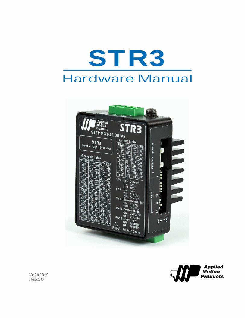
1 IntroductionThank you for selecting the Applied Motion Products STR3 step motor drive. We hope our commitment to performance, quality and economy will make a successful motion control project. The STR3 Step motor drive is a cost-effective, high performance drive. The design is based on advanced digital current control technology, and features high torque, low noise and low vibration. Running current, microstep resolution, and other parameters are switch selectable so software configuration is not required.
1.1 Features• Power Supply - Operates from a 12 to 48 volt DC power supply• Inputs - 3 optically isolated digital inputs, 5 to 24 volts• Speed Range - up to 3000 rpm• Current Control - 3 piano switch setting running current, 3 Amps peak maximum• Idle Current - Switch selectable for reduction to 50% or 90% of running current 1 second after the motor stops• Self Test - Performs a 2 rev, 1 rps, CW/CCW move test, switch selectable: ON or OFF• Control Mode - Step & Direction mode, CW/CCW mode• Microstep Resolution - 4 piano Switch selectable, 16 settings: 200, 400, 800, 1600, 3200, 6400, 12800, 25600, 1000,
2000, 4000, 5000, 6000, 8000, 10000, 20000 steps/rev
1.2 Block Diagram

5
STR3 Hardware Manual920-0102 Rev. E
01/25/2018
1.3 Safety InstructionsOnly qualified personnel should transport, assemble, install, operate, or maintain this equipment. Properly qualified personnel are persons who are familiar with the transport, assembly, installation, operation, and maintenance of motors, and who meet the appropriate qualifications for their jobs.
To minimize the risk of potential safety problems, all applicable local and national codes regulating the installation and opera-tion of equipment should be followed. These codes may vary from area to area and it is the responsibility of the operating personnel to determine which codes should be followed, and to verify that the equipment, installation, and operation are in compliance with the latest revision of these codes.
Equipment damage or serious injury to personnel can result from the failure to follow all applicable codes and standards. Ap-plied Motion Products does not guarantee the products described in this publication are suitable for a particular application, nor do they assume any responsibility for product design, installation, or operation.
• Read all available documentation before assembly and operation. Incorrect handling of the products referenced in this manual can result in injury and damage to persons and machinery. All technical information concerning the installation requirements must be strictly adhered to.
• It is vital to ensure that all system components are connected to earth ground. Electrical safety is impossible without a low-resistance earth connection.
• This product contains electrostatically sensitive components that can be damaged by incorrect handling.• Follow qualified anti-static procedures before touching the product.• During operation keep all covers and cabinet doors shut to avoid any hazards that could possibly cause severe damage to
the product or personal health.• During operation the product may have components that are live or have hot surfaces.• Never plug in or unplug the step motor drive while the system is live. The possibility of electric arcing can cause damage.
Be alert to the potential for personal injury. Follow all recommended precautions and safe operating practices. Safety notices in this manual provide important information. Read and be familiar with these instructions before attempting installation, opera-tion, or maintenance.The purpose of this section is to alert users to the possible safety hazards associated with this equipment and the precautions necessary to reduce the risk of personal injury and damage to equipment. Failure to observe these precautions could result in serious bodily injury, damage to the equipment, or operational difficulty.

6
STR3 Hardware Manual920-0102 Rev.E01/25/2018
2 Getting StartedTo use the STR3 step motor drive, the following items are needed:• A 12 - 48 volt DC power supply, see the section below entitled “Choosing a Power Supply” for help in choosing the right
one• Step & Direction signals• A small flat blade screwdriver for configuring the switches (included) 2.1 Mounting the HardwareAs with any step motor, the STR3 must be mounted so as to provide maximum heat sinking and airflow. Keep enough space around the Step motor drive to allow for airflow.
• Never use the drive where there is no airflow or where other devices cause the surrounding air to be more than 40°C (104°F).• Never put the drive where it can get wet.• Never use the drive where metal or other electrically conductive particles can infiltrate the drive.• Always provide airflow around the drive.
2.2 Choosing a Power SupplyWhen choosing a power supply, there are many things to consider. If you are manufacturing equipment that will be sold to oth-ers, you probably want a supply with all the safety agency approvals. If size and weight are an issue get a switching supply.Also, you must decide what size of power supply (in terms of voltage and current) is needed for your application.Applied Motion offers three powers supplies that are excellent matches for the STR3 drive: PS50A24 (24V, 2.1A), PS150A24 (24V, 6.3A) and PS320A48 (48V, 6.7A).
2.2.1 Supply Voltage Your motor can provide more torque at higher speeds if a higher power supply voltage is used. Please consult the speed-torque curves later in this manual for guidance.If you choose an unregulated power supply, make sure the no load voltage of the supply does not exceed the drive’s maximum input voltage specification.
2.2.2 Supply CurrentThe maximum supply current you could ever need is two times the motor current. However, you will generally need a lot less than that, depending on the motor type, voltage, speed and load conditions. That’s because the STR uses a switching amplifier, converting a high voltage and low current into lower voltage and higher current. The more the power supply voltage exceeds the motor voltage, the less current you’ll need from the power supply. A motor running from a 48 volt supply can be expected to draw only half the supply current that it would with a 24 volt supply.

7
STR3 Hardware Manual920-0102 Rev. E
01/25/2018
We recommend the following selection procedure:1. If you plan to use only a few drives, get a power supply with at least twice “per phase” current rating of the step motor. Example: for a motor that’s rated for 2 A/phase use a 4A power supply.2. If you are designing for mass production and must minimize cost, get one power supply with more than twice the rated cur-rent of the motor. Install the motor in the application and monitor the current coming out of the power supply and into the drive at various motor loads. This will tell you how much current you really need so you can design in a lower cost power supply.
The table below list the maximum current required for each motor at several common power supply voltages. Please consider this information when choosing a power supply.
Motor Connection Current Setting (A)
Max Power Supply Current (A)
12VDC 24VDC 48VDC
HT08-020 4 leads 0.40 0.95A 0.95A N/A
HT08-021 4 leads 0.40 0.95A 0.95A N/A
HT11-012 4 leads 1.20 0.6A 0.6A N/A
HT11-013 4 leads 1.20 0.95A 0.95A N/A
HT17-268 parallel 1.60 1.0A 1.0A 1.0A
HT17-271 parallel 2.00 1.3A 1.3A 1.3A
HT17-275 parallel 2.00 1.32A 1.32A 1.32A
HT23-595 series 2.40 1.36A 1.36A 1.36A
HT23-598 series 2.40 1.56A 1.56A 1.56A
HT23-601 series 2.40 1.4A 1.4A 1.4A
HT23-394 parallel 3.0 N/A 2.0A 3A
HT24-100 4 leads 3.0 N/A 1.2A 1.75A
2.2.3 Multiple Drives Sharing One Power SupplyYou can use one supply to power multiple drives. The worst case condition occurs when all the drives are running simultaneously. In this case, just add up the power supply currents for each to determine the total power supply current requirement.

8
STR3 Hardware Manual920-0102 Rev.E01/25/2018
3 Connections3.1 Connector Signals

9
STR3 Hardware Manual920-0102 Rev. E
01/25/2018
3.1.1 Connect Main Power Supply If the power supply does not have a fuse on the output or some kind of short circuit current limiting device a fast acting fuse is required. A 3 Amp fast acting fuse should be installed in line with the “+” power supply lead.
Connect the power supply “+” terminal to the drive “ V+” terminal. Connect the power supply “-” terminal to the drive “ V-” terminal.
Be careful not to reverse the “+” and “-” wires. Reversing the connection may open the internal fuse on the drive and void the warranty.
If a regulated power supply is being used, there may be a problem with regeneration. When a load decelerates rapidly from a high speed, some of the kinetic energy of the load is transferred back to the power supply, possibly tripping the over-voltage protection of a regulated power supply, causing it to shut down. This problem can be solved with the use of A Applied Motion Products RC880 Regeneration Clamp. It is recommended that an RC880 initially be installed in an application. If the “regen” LED on the RC880 never flashes, the clamp is not necessary.

10
STR3 Hardware Manual920-0102 Rev.E01/25/2018
3.1.2 Connector Pin Diagram
3.1.3 STEP and DIR InputsThe STR3 step motor drive has two high speed optically isolated inputs called STEP and DIR. They accept 5 to 24 volt single-ended or differential signals, up to 500KHz. The maximum voltage that can be applied to the input is 28V.
The motor executes one step when the STEP input closes.
The direction of rotation is controlled by the DIR input state. A closed input (logic “0”) will result in clockwise rotation, and an open input (logic “1”) will result in counterclockwise rotation.

11
STR3 Hardware Manual920-0102 Rev. E
01/25/2018
3.1.4 EN Input The EN input enables or disables the drive Amplifier. It is an optically isolated input that acceptsa 5 to 24 volt single-ended or differential signal. The maximum voltage that can be applied to the input is 28V.
When EN input is closed, the drive Amplifier is deactivated. All the MOSFETs will shut down, andthe motor is free. When EN input is open, the drive is activated.
When the drive has encountered an error and the fault is removed from system, a falling signalinto the EN input will reset the error status and activate the drive Amplifier again.

12
STR3 Hardware Manual920-0102 Rev.E01/25/2018
3.2 Switch SelectingThe EN input enables or disables the drive Amplifier. It is an optically isolated input that acceptsa 5 to 24 volt single-ended or differential signal. The maximum voltage that can be applied to the input is
3.2.1 Running CurrentThe output current of the STR3 step motor drive is set by the SW1, SW2 and SW3 switches and can be changed as necessary. There are 8 settings available according to the ON/OFF combination of the switches.

13
STR3 Hardware Manual920-0102 Rev. E
01/25/2018
3.2.2 Idle CurrentThe running current of the STR3 is automatically reduced whenever the motor isn’t moving. Setting the SW4 switch to ON maintains 50% of the running current. Setting this switch to OFF maintains 90% of the running current. This 90% setting is useful when a high holding torque is required. To minimize motor and drive heating it is highly recommended that the idle current reduction feature be set to 50% unless the application requires the higher setting.
3.2.3 MicroStep SettingSTR3 setting switch SW5, SW6, SW7, SW8. There are 16 settings.

14
STR3 Hardware Manual920-0102 Rev.E01/25/2018
3.2.4 Self TestA built-in self-test feature is available on the STR3 to check the physical operation of the motor. Setting switch SW9 to ON after the drive is powered up will cause the drive to perform a self test move of 2 revolutions both CW and CCW at 1rps. Setting switch SW9 to OFF disables this feature.
3.2.5 Step Smoothing FilterCommand signal smoothing can soften the effect of immediate changes in velocity and direction, making the motion of the motor less jerky. An added advantage is that it can reduce the wear on mechanical components. SW10 selects this function - ON enables it, OFF disables it.
This function can cause a small delay in following the control signal, and it should be used with that in mind
3.2.6 Control ModeSwitch SW11 sets control mode. Switch OFF sets the Step & Dir mode. Switch ON sets the CW/ CCW mode
3.2.7 Step Noise FilterSwitch SW12 sets the digital signal filter. The STEP and DIR signal inputs have built-in digital filters and this setting will reduce external noise. If the system works on the low microstep, select the 150 KHz (ON) setting. If the system works on the high microstep, select the 500KHz (OFF) setting

15
STR3 Hardware Manual920-0102 Rev. E
01/25/2018
4 Motor SelectionMotor wires setting:

16
STR3 Hardware Manual920-0102 Rev.E01/25/2018
5 Troubleshooting LED ERROR CODES
The STR3 has one bicolor (red/green) LED to indicate status and errors. When the motor is enabled, the LED slowly flashes green. When the LED is solid green, the motor is disabled. If the LED flashes red, an error has occurred. Errors are indicated by a combination of red and green flashes as follows:

17
STR3 Hardware Manual920-0102 Rev. E
01/25/2018
6 Reference Materials
6.1 Mechanical Outline

18
STR3 Hardware Manual920-0102 Rev.E01/25/2018
6.2 Technical SpecificationsPower AmplifierAmplifier Type Dual H-Bridge, 4 QuadrantCurrent Control 4 state PWM at 16 KHzPower Supply External 12 - 48 volt power supply requiredInput Voltage Range 10 - 53 volts min/max (nominal 12 - 48 volts), voltages outside
this range will cause driver faults and/or may damage the driveProtection Over-voltage, over-current, under-voltage, over-temp, internal mo-
tor shorts (phase-to-phase, phase-to-ground)Ambient Temperature 0 - 40°C (32 - 104°F) when mounted to a suitable heat sinkHumidity 90% non-condensing
ControllerCurrent Control Advanced digital current control provides excellent high speed
torqueSpeed Range Speeds up to 3000 rpmAuto Setup Measures motor parameters to configure current control and anti-
resonance gain settingsStep Input STEP+/- Inputs: optically isolated, 5 - 24 volts, min. pulse width 250 us.,
max. pulse frequency 500KHz; motor executes one step when the STEP input closes
Direction Input DIR+/- Inputs: optically isolated, 5 - 24 volts, min. pulse width 62.5 us., max. pulse frequency 500KHz; direction of rotation is controlled by the DIR input state
Enable Input EN+/- Inputs: optically isolated, 5 - 24 volts, min. pulse width 500 us., max. pulse frequency 10 KHz; enables or disables the drive Ampli-fier
Running Current Switch selectable, 8 settings: 3 Amps peak maximumIdle Current Reduction Automatically reduces the current 1 second after the motor stops;
switch selectable, 2 settings: 50% or 90% of the running currentMicrostep Resolution Switch selectable, 16 settings: 200, 400, 800, 1600, 3200,
6400, 12800, 25600, 1000, 2000, 4000, 5000, 6000, 8000, 10000, 20000 steps/rev
Self Test Checks internal and external power supply voltages, 2 rev move both CW and CCW at 1rps, switch selectable, ON or OFF
Modes Of Control Step & Direction, CW/CCW control

19
STR3 Hardware Manual920-0102 Rev. E
01/25/2018
6.3 Torque Curves

20
STR3 Hardware Manual920-0102 Rev.E01/25/2018

21
STR3 Hardware Manual920-0102 Rev. E
01/25/2018
6.4 Motor HeatingStep motors convert electrical power from the driver into mechanical power to move a load. Because step motors are not per-fectly efficient, some of the electrical power turns into heat on its way through the motor. This heating is not so much depen-dent on the load being driven but rather the motor speed and power supply voltage. There are certain combinations of speed and voltage at which a motor cannot be continuously operated without damage.
We have characterized the recommended motors in our lab and provided a table and several curves showing the maximum duty cycle versus speed for each motor at commonly used power supply voltages. Please refer to this information when planning your application.
Please also keep in mind that a step motor typically reaches maximum temperature after 30 to 45 minutes of operation. If you run the motor for one minute then let it sit idle for one minute that is a 50% duty cycle. Five minutes on and five minutes off is also 50% duty. However, one hour on and one hour off has the effect of 100% duty because during the first hour the motor will reach full (and possibly excessive) temperature.
The actual temperature of the motor depends on how much heat is conducted, convected or radiated out of it. Our measure-ments were made in a 40°C (104°F) environment with the motor mounted to an aluminum plate sized to provide a surface area consistent with the motor power dissipation. Your results may vary.
Motor Connection Current Setting (A)
Max Duty Cycle at 40°C Ambient12VDC 24VDC 48VDC
HT08-020 4 leads 0.4 100% 100% NRHT08-021 4 leads 0.4 100% 100% NRHT11-012 4 leads 1.20 100% 100% NRHT11-013 4 leads 1.20 100% 100% NRHT17-268 parallel 1.6 100% 100% see chartHT17-271 parallel 2.0 100% 100% see chartHT17-275 parallel 2.0 100% 100% see chartHT23-595 series 2.40 100% 100% 100%HT23-598 series 2.40 100% 100% 100%HT23-601 series 2.40 100% 100% 100%HT24-100 4 leads 3 100% 100% 100%

22
STR3 Hardware Manual920-0102 Rev.E01/25/2018

23
STR3 Hardware Manual920-0102 Rev. E
01/25/2018
Applied Motion Products, Inc.404 Westridge Drive Watsonville, CA 95076
Tel (831) 761-6555 (800) 525-1609www.applied-motion.com