stormwater management - sswm · handbook stormwater management the commonwealth of massachusetts...
TRANSCRIPT

March 1997
Prepared by:
Stormwater ManagementVolume Two: Stormwater Technical
Handbook
MA Department of Environmental Protection
MA Office of Coastal Zone Management

March 1997
Volume Two: Stormwater TechnicalHandbook
Stormwater Management
The Commonwealth of MassachusettsWilliam F. Weld, Governor
Argeo Paul Cellucci, Lieutenant Governor
Executive Office of Environmental AffairsTrudy Coxe, Secretary
Department of Environmental ProtectionDavid B. Struhs, Commissioner
Bureau of Resource ProtectionArleen O’Donnell, Assistant Commissioner
This information is available in alternate formats upon request.
Printed on recycled paper.
Funding for this document was provided by:w Massachusetts Department of Environmental Protection,w Massachusetts Office of Coastal Zone Management, andw U.S. Environmental Protection Agency.
The document also was partially funded by a grant from the Office ofOcean and Coastal Resources Management, National Oceanic andAtmospheric Administration, U.S. Department of Commerce. The viewsexpressed are those of the author(s) and do not necessarily reflect theviews of NOAA or any of its subagencies.

Stormwater Management (Volume Two)
Table of Contents
Table of Contents
CHAPTER 1: Hydrology and Stormwater Runoff ...........1-1The Hydrologic Cycle................................................................................ 1-1Stormwater Runoff .................................................................................... 1-2Development and Stormwater Quantity .................................................... 1-2Development and Stormwater Quality ...................................................... 1-5Controlling Stormwater Runoff .................................................................. 1-7
CHAPTER 2: Site Planning and NonstructuralApproaches ....................................................................2-1Site Planning ............................................................................................ 2-1Site Planning Techniques that will Minimize Runoff .................................. 2-2Nonstructural Approaches: Source Controls and Pollution Prevention .... 2-7
CHAPTER 3: Structural Best Management Practices ...3-1The BMP Selection Process ..................................................................... 3-2The BMP Sizing Process ....................................................................... 3-10[Extended] Detention Basins ................................................................. 3.A-1Wet [Retention] Ponds .......................................................................... 3.B-1Constructed [Stormwater] Wetlands ......................................................3.C-1Water Quality Swales ............................................................................3.D-1Infiltration Trenches ............................................................................... 3.E-1Infiltration Basins ................................................................................... 3.F-1Dry Wells .............................................................................................. 3.G-1Sand Filters/Organic Filters ...................................................................3.H-1Water Quality Inlets/Deep Sump Catch Basins ...................................... 3.I-1Sediment Traps [Forebays].................................................................... 3.J-1Drainage Channels ................................................................................ 3.K-1
APPENDIX A: Glossary ............................................................................ A-1APPENDIX B: Bibliography ...................................................................... B-1APPENDIX C: Contacts............................................................................C-1APPENDIX D: Reviewing and Conditioning InnovativeStormwater Control BMPs ........................................................................D-1APPENDIX E: NPDES Stormwater Permit Program ................................E-1

Stormwater Management (Volume Two)
Hydrology and Stormwater Runoff
1-1
CHAPTER 1: Hydrology and Stormwater Runoff
The Hydrologic CycleHydrology is the movement of water. In the hydrologic cycle, rain or snowfrom clouds falls to the ground, and as water or snow melt:w infiltrates or seeps into the ground, a process called percolation;w is taken up by the trees and vegetation and is returned to the atmo-
sphere through transpiration, or evaporation of water from all surfaces;or
w runs over the ground surface.
Water that seeps into the ground travels underground until eventuallyreaching the groundwater table and possibly surface waters such as a lake,stream, or the ocean. This process, called groundwater recharge, helpsmaintain water flow in streams and wetlands and preserves water tablelevels that support drinking water supplies. The amount of recharge thatoccurs on a site is based on slope, soil type, vegetation and other cover, aswell as precipitation and evapotranspiration rates. Sites with naturalground cover, such as forest, meadow, or shrubs, typically have greaterrecharge rates, less runoff, and higher transpiration than sites with pave-ment and buildings.
The water that runs off the ground surface as overland flow is runoff.Through evaporation from surface waters, water is returned to the atmo-sphere, new clouds are formed, and the hydrologic cycle begins again.
The hydrologic cycle (Massachusetts Audubon Society, 1983)

Stormwater Management (Volume Two)
Hydrology and Stormwater Runoff
1-2
Stormwater RunoffRunoff is a natural part of the hydrologic cycle. The volume and speed ofrunoff depends on the size of the storm (how much water falls in whatamount of time) and the land features at the site. The size of the contribut-ing drainage area, the slope of the land, the types of soils, and the surfaceconditions (such as woods or pavement) affect water movement. Thecontributing drainage area establishes the boundary limits for the move-ment of runoff - from the highest elevations to the lowest point. A water-shed is a region that consists of one or more contributing drainage areas toa body of water.
In a natural, undeveloped setting, the ground’s surface often is pervious,meaning water can percolate down into the soil. In developed areas,ground surfaces are often asphalt, concrete, and other materials which areimpervious and prevent water from infiltrating into the soil. Water whichcannot be absorbed into the ground becomes runoff. Water that falls duringand immediately after a storm and flows over impervious surfaces orotherwise cannot be absorbed into the ground is called stormwater runoff.
Stormwater runoff that flows into and is discharged through a pipe, ditch,channel, or other structure is considered a point source discharge. Con-taminated stormwater runoff that flows over land and is not directed into adefined channel is considered nonpoint source pollution. Both point andnonpoint source pollution significantly degrade water quality and aquatichabitat. The difference between nonpoint and point source types of pollu-tion becomes less clear when stormwater flows over land and then intostorm drains and other types of collection systems before it is dischargedthrough a pipe to a water body. In these cases, stormwater runoff begins asa nonpoint source and becomes a point source discharge.
Development and Stormwater QuantityDevelopment - the construction of homes and other buildings, streets,parking lots, and other man-made features - can alter the hydrology of thelandscape and adversely affect water quality. Development changes landuse and generally increases the amount of stormwater runoff from a site.Stormwater runoff can cause erosion and flooding. Development canchange water flow and the percolation of water into the soil, which affectshow much water can infiltrate into the ground to maintain water levels instreams, wetlands, and groundwater aquifers. Stormwater runoff alsoaffects water quality, which can have adverse impacts on aquatic plants andanimals.
During development, vegetated and forested land with pervious surfacesare replaced by land uses with impervious surfaces. Impervious surfacestransform hydrology and impact aquatic habitats by changing the rate andvolume of runoff and altering natural drainage features, including ground-water levels. Changes in water quantity begin with the initial site clearing

Stormwater Management (Volume Two)
Hydrology and Stormwater Runoff
1-3
and grading. Vegetation which intercepted rainfall and reduced runoff isremoved. Natural depressions which provided temporary storage of rainfallare filled and graded. Soils are exposed and compacted resulting in in-creased sedimentation and decreased infiltration. Having lost much of itsnatural storage capacity, the cleared, graded site allows rainfall to rapidlybecome runoff.
Once the development has been completed, the increase in impervious area(rooftops, roads, driveways, and parking lots) reduces the amount ofrainfall that can be infiltrated, which increases the volume of runoff. Figure1.1 shows the relationship of runoff, infiltration, and evaporation withvarying degrees of impervious cover. Table 1.1 indicates the typical per-centages of impervious cover for various land uses. The percentage ofimperviousness in a watershed is a useful measure of land developmentimpacts on streams and aquatic systems. Studies show that hydraulic andbiological changes to streams occur when 10 to 20 percent of a watershedhas impervious surfaces. Moreover, efforts to restore stream flow andwater quality to pre-development conditions appear to be less successfulwhen levels of impervious cover exceed 30 percent.
Figure 1.1: Typical Changes in Runoff Flows Resulting From Paved Surfaces(Minnesota Pollution Control Agency (MPCA), 1989)

Stormwater Management (Volume Two)
Hydrology and Stormwater Runoff
1-4
Table 1.1: Typical Impervious Area Percentages (MPCA, 1989)
Land Use % Impervious Cover
Business District or Shopping Center 95-100
Residential, High Density 45-60
Residential, Medium Density 35-45
Residential, Low Density 20-40
Open Areas 0-10
The impacts of development on hydrology may include:
w Increased peak discharges of runoff compared to pre-developmentlevels;
w Increased volume of runoff produced by each storm in comparison topre-development conditions;
w Decreased time in which runoff reaches the stream, particularly if exten-sive drainage changes are made;
w Increased frequency and severity of offsite downstream flooding;
w Reduced stream flow and lower water table levels during prolongedperiods of dry weather due to reduced infiltration in the watershed;
w Loss of wetlands and aquatic habitats due to lower water table levelsduring dry weather;
w Greater runoff velocity during storms due to increased impervious areas,which move greater volumes of runoff at a faster rate; and
w Increased frequencies and prolonged periods of high stream flow veloci-ties that can significantly increase stream channel erosion.
Stormwater Management (Volume Two)
Hydrology and Stormwater Runoff
1-5
Development and Stormwater QualityStormwater runoff carries a variety of contaminants that affect waterquality. These contaminants come from different residential, commercial,and industrial land uses within a watershed. People’s daily activities leavepollutants, such as pesticides, fertilizers, animal wastes, sediments, nutri-ents, and heavy metals, on the surface of the ground. Stormwater runoffcarries the pollutants on the ground into nearby water bodies and water-ways. As development increases and activities change and intensify, theconcentrations and types of contaminants also increase. Although all landuses can affect water quality, in undeveloped areas natural processes canlessen the impacts of contaminants or even remove contaminants fromrunoff through infiltration and evaporation. Impervious areas reduce theopportunity for natural processes to treat stormwater. Therefore, stormwa-ter runoff must be adequately controlled and treated to reduce pollutantsbefore it is discharged to surface water, groundwater, or wetlands.
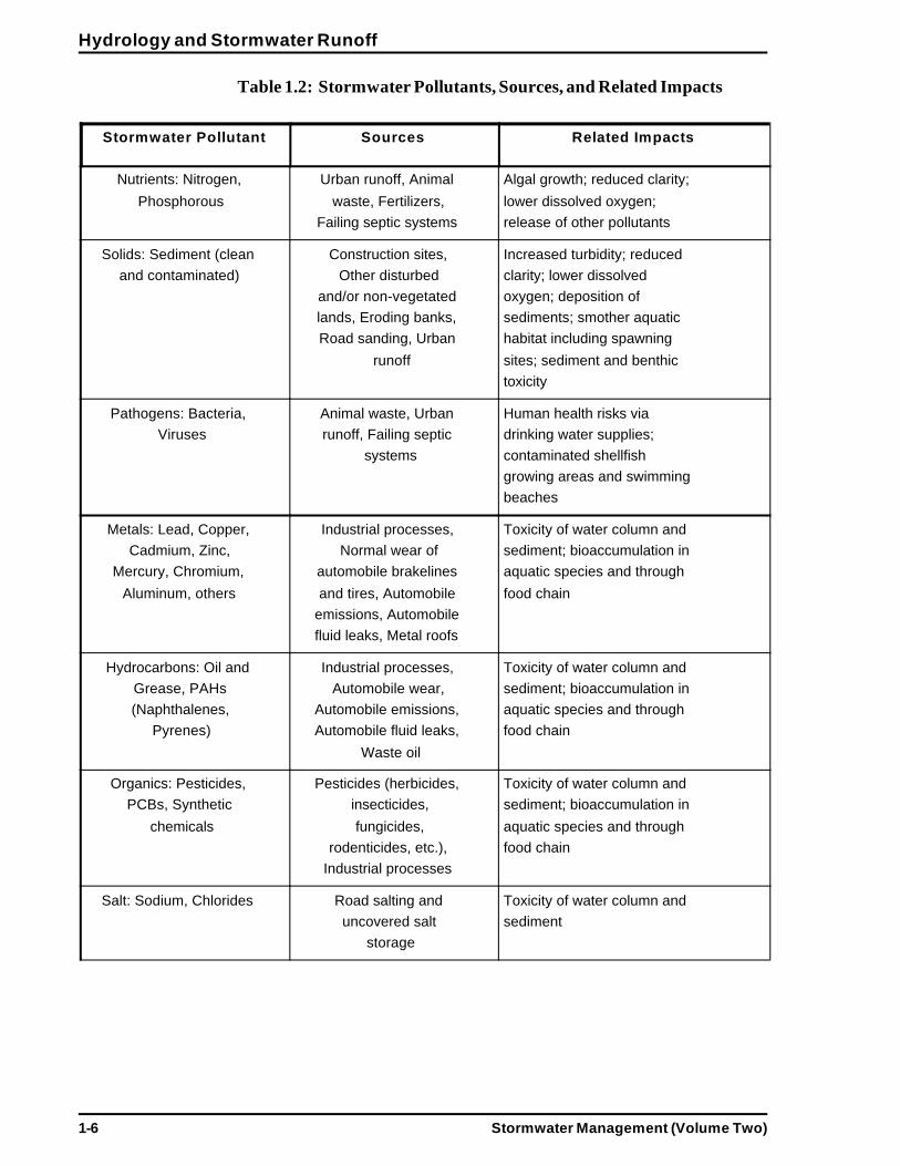
A summary of the principal pollutants found in runoff, their sources, andrelated impacts is provided in Table 1.2. DEP’s Nonpoint Source Manage-ment Manual (1993) provides a detailed description of land use activitiesthat are major contributors of nonpoint source pollution (see Appendix Cfor more information).
Stormwater Management (Volume Two)
Hydrology and Stormwater Runoff
1-6
Table 1.2: Stormwater Pollutants, Sources, and Related Impacts
Stormwater Pollutant Sources Related Impacts
Nutrients: Nitrogen,Phosphorous
Urban runoff, Animalwaste, Fertilizers,
Failing septic systems
Algal growth; reduced clarity;lower dissolved oxygen;release of other pollutants
Solids: Sediment (cleanand contaminated)
Construction sites,Other disturbed
and/or non-vegetatedlands, Eroding banks,Road sanding, Urban
runoff
Increased turbidity; reducedclarity; lower dissolvedoxygen; deposition ofsediments; smother aquatichabitat including spawningsites; sediment and benthictoxicity
Pathogens: Bacteria,Viruses
Animal waste, Urbanrunoff, Failing septic
systems
Human health risks viadrinking water supplies;contaminated shellfishgrowing areas and swimmingbeaches
Metals: Lead, Copper,Cadmium, Zinc,
Mercury, Chromium,Aluminum, others
Industrial processes,Normal wear of
automobile brakelinesand tires, Automobile
emissions, Automobilefluid leaks, Metal roofs
Toxicity of water column andsediment; bioaccumulation inaquatic species and throughfood chain
Hydrocarbons: Oil andGrease, PAHs(Naphthalenes,
Pyrenes)
Industrial processes,Automobile wear,
Automobile emissions,Automobile fluid leaks,
Waste oil
Toxicity of water column andsediment; bioaccumulation inaquatic species and throughfood chain
Organics: Pesticides,PCBs, Synthetic
chemicals
Pesticides (herbicides,insecticides,fungicides,
rodenticides, etc.),Industrial processes
Toxicity of water column andsediment; bioaccumulation inaquatic species and throughfood chain
Salt: Sodium, Chlorides Road salting anduncovered salt
storage
Toxicity of water column andsediment
Stormwater Management (Volume Two)
Hydrology and Stormwater Runoff
1-7
Controlling Stormwater RunoffThere are a variety of controls to manage stormwater runoff from a site.These control measures may address different aspects of runoff: storage ofrunoff water, infiltration of stormwater to groundwater, and treatment ofthe pollutants in stormwater. Proper peak runoff rate control helps preventadverse impacts such as stream channel scouring and bank alteration andminimizes downstream flooding and stream bank erosion. In general,protection from stream bank erosion requires the control of frequentflooding events (i.e., the 2-year and smaller storm events). These stormshave the most influence on stream channel formation. Protection from lesscommon, offsite flooding requires the control of storm events whichexceed stream channel bankfull capacity (i.e., the 10-year and higherevents).
Engineers may design drainage systems or other physical structures, suchas detention and infiltration basins, pretreatment devices, and swales, tomanage stormwater. Nonstructural approaches also may control or reducestormwater runoff. For example, by reducing the building footprint whileincreasing the building height, more grassy areas can be preserved and newimpervious surfaces can be minimized.
Nonstructural and structural Best Management Practices (BMPs) arerecognized as the most effective and practical measures to reduce orprevent pollutants from reaching water bodies and to control the quantityof runoff from a site. However, stormwater BMP technologies range intheir ability and effectiveness to treat specific pollutant types. Dependingon the receiving resources, the pollutant type of concern will vary. Fordrinking water supplies, inorganic compounds, volatile organic compounds,pesticides, herbicides, and pathogens (bacteria and viruses) are the mainconcern. For shellfish growing areas and recreation areas, bacterial con-tamination and nutrients are primary concerns, while temperature and pHare the major concerns for cold water fisheries.
The Stormwater Management Standards require the use of BMPs based ondifferent site conditions and establish post-development goals for stormwa-ter controls. Applicants have the flexibility to choose the most appropriatecontrols for a particular site.

Stormwater Management (Volume Two) 2 - 1
Site Planning and Nonstructural Approaches
CHAPTER 2: Site Planning andNonstructural Approaches
To meet the Stormwater Management Standards, a project proponent mayutilize three basic methods in this order:
w Design the development utilizing site planning techniques to minimizerunoff;
w Utilize nonstructural techniques, including pollution prevention andsource reduction to minimize the type of treatment the stormwaterneeds; and
w Construct and maintain structural Best Management Practices (BMPs) tocapture and treat the stormwater runoff.
Applicants may select the methodology to meet the Stormwater Manage-ment Standards. However, the most cost-effective means is often throughsite planning and the nonstructural approaches discussed in this Chapter.Maintaining pre-development hydrologic conditions through proper siteplanning and nonstructural approaches, including implementing erosion andsediment controls, are highly effective pollution prevention and reductionmeasures which can reduce or even eliminate the need for structural BMPs.This approach will result in a well designed development plan and associ-ated stormwater management system that suits land constraints and mini-mizes costs.
Site PlanningSite planning that integrates comprehensive stormwater management intothe site development process from the outset is the most effective approachto reduce and prevent potential pollution and flooding problems. Earlystormwater management planning will generally minimize the size and costof structural solutions. Stormwater management efforts which incorporateBMP structural technologies into the site design at the final stages fre-quently result in the construction of unnecessarily large and costly facilities,which may fail due to improper design, siting, engineering, or operation.
Who Does Site Planning for Stormwater?Site planning is the responsibility of the project proponent. The StormwaterManagement Standards will not be the only applicable requirementsprojects must meet. Certain components of site planning may requiretechnical (hydrology or engineering) expertise, and in such cases, compre-hensive site planning should be done by professional consultants and/ordesign engineers. Before and during the permit review process, collabora-tive efforts among various parties, including developers, consultants,technical staff, planning boards, and conservation commissions will fre-quently lead to final design plans that meet mutual goals.

Stormwater Management (Volume Two)2 - 2
Site Planning and Nonstructural Approaches
How is Site Planning Required and Who Reviews Site Plans forStormwater Management?
In most cases, site plan review is conducted at the local level by the plan-ning board and additionally by the conservation commission pursuant to theWetlands Protection Act when the project is located in a wetland resourcearea.
Planning boards also ensure proper stormwater management is accom-plished through site plan review conducted under the authority of theSubdivision Control Act or local regulations. Local zoning bylaws, forexample, may establish special requirements for additional review throughzoning districts or special permits that may require more stringent protec-tion than the Stormwater Management Standards in order to minimize thecreation of new runoff or provide a higher level of protection for drinkingwater supplies and other critical resources, such as nitrogen sensitiveembayments. The Nonpoint Source Management Manual published byDEP (1993) provides additional information on site plan review and storm-water planning.
Site Planning Techniques that will Minimize RunoffComprehensive site planning is critical to stormwater management becauseit can eliminate unnecessary increases in runoff and reduce sediment/erosion problems. Modern stormwater management and sediment/erosioncontrol have replaced the former approach of treating stormwater aswastewater and moving runoff offsite as quickly as possible with little or noregard for downstream consequences and long-term hydrologic and waterquality impacts. Careful site designs will minimize the size and relatedmaterial, construction, and maintenance costs of structural stormwatercontrols.
Site planning should include the preparation of accurate and complete siteplan maps and narratives. Stormwater controls must be developed for bothconstruction activities and post-construction conditions, which should beaddressed separately in the plans and narrative descriptions provided withthe Notice of Intent under the Wetlands Protection Act. Site planningtechniques that will minimize the creation of new runoff and provideremoval of some suspended solids include:
Minimize Impervious SurfacesReplacing natural cover and soils with impervious surfaces will lead toincreased runoff volume and velocity, larger pollutant loads, and mayadversely affect long-term hydrology and natural systems through floodingand channel erosion. Research demonstrates a marked drop in fish, amphib-ian, and insect species when the percent imperviousness within a watershedexceeds the 10 to 15% range. Careful site planning can reduce the impervi-ous area created by pavement and roofs and the volume of runoff andpollutant loading requiring control.

Stormwater Management (Volume Two) 2 - 3
Site Planning and Nonstructural Approaches
Moreover, as the impervious surface area of a development increases, thesize and expense of the quantity control facilities also increase. Techniquesto reduce runoff volumes and velocities, such as the minimization of imper-vious surfaces, will help mitigate this issue. Local zoning codes and devel-opment standards, such as road widths or cluster zoning, affect the amountof runoff generated by projects. Development practices that require morethan the minimum necessary area of impervious surface and use extensiveconveyance networks that increase the flow of stormwater runoff intoreceiving waters, often end up creating more costly problems than theysolve.
While it is generally important to minimize the creation of impervioussurfaces, it is absolutely essential in certain recharge areas. Note that theMassachusetts Drinking Water Regulations (310 CMR 22.00) require thedelineation of recharge areas (Zone IIs) and place land use prohibitions andrestrictions in those areas for new wells (rated for >100,000 gallons perday) and for existing wells that increase pumping by 100,000 gallons perday. One restriction prohibits land uses which render impervious more than15% or 2,500 square feet of a lot, whichever is greater, unless a system forartificial recharge of precipitation is provided that will not result in thedegradation of groundwater quality.
Certain site planning methods will minimize impervious surfaces andreduce the volume of runoff. These include:
w Maintain natural buffers and drainageways: Natural buffers locatedbetween development sites and wetlands infiltrate runoff, reduce runoffvelocity, and remove some suspended solids. Natural depressions andchannels act to slow and store water, promote sheet flow and infiltra-tion, and filter pollutants.
w Minimize the creation of steep slopes: Steep slopes have significantpotential for erosion and increasing sediment loading. Slopes steeperthan 2:1 should be avoided unless stringent stabilization methods areemployed.
w Minimize placement of new structures or roads over porous or erodiblesoils: Porous soils provide the best and cheapest mechanism for infiltrat-ing stormwater and reducing runoff volume and peak discharge, as wellas providing ground water recharge and treatment by infiltration andadsorption through the soil strata. Disturbance of unstable soils shouldbe avoided due to their greater erosion potential.
w Reduce frontage and other setbacks.
w Establish Planned Unit Developments through zoning that limits thedensity of development while maximizing the amount of undisturbedopen space.

Stormwater Management (Volume Two)2 - 4
Site Planning and Nonstructural Approaches
w Establish Cluster Developments through zoning that clusters or groupsbuildings closer together to maximize the amount of undisturbed openspace.
w Reduce the horizontal footprint of buildings and parking areas. Foot-print size can be reduced by constructing a taller building, includingparking facilities within the building itself, while maintaining the samefloor to area (FAR) ratio.
w Reduce to one lane, or eliminate if practical, on-street parking lanes onlocal access roads.
w Limit sidewalks to one side, or eliminate if practical, on local low trafficroads.
w Use shallow grassed roadside swales and parking lot islands with checkdams instead of curb and gutter storm drainage systems to handle runoffand snow storage. Guidelines for the use of drainage channels and waterquality swales can be found in Chapter 3 of this Volume.
w Utilize “turf pavers,” gravel, or other porous surfaces when possible forsidewalks, driveways, transition areas between pavement edge andswales, or overflow parking areas.
w Maintain as much of the pre-development vegetation as possible, espe-cially larger trees that may be on site. Vegetation absorbs water, whichwill reduce the amount of stormwater runoff. Proposed structuresshould be sited to minimize shading effects on vegetation and rootsshould be protected from damage during the construction phase.
Fit the Development to the TerrainRoad patterns should match the landform. For example, in rolling terrain,local streets should branch from collector streets, ending in short loops orcul-de-sacs along ridgelines. In areas where the topography is characteristi-cally flat, the use of grids may be more appropriate. In these schemes,natural drainageways are preserved by interrupting and bending the roadgrid around them. Grassed waterways, vegetated drainage channels, orwater quality swales may then be constructed along street right-of-ways oron the back of lots to channel runoff without abrupt changes in the direc-tion of flow.
Preserve and Utilize Natural Drainage SystemsThe standard approach of using curbing on streets and parking areasimpairs natural drainage systems. Curbs are widely held to be the signatureof quality development; they provide a neat, “improved” appearance andalso help delineate roadway edges. Because curb and gutter streets traprunoff in the roadbed, storm inlets and drains are logical solutions toproviding good drainage for the roadbed.

Stormwater Management (Volume Two) 2 - 5
Site Planning and Nonstructural Approaches
Unfortunately, a requirement for curb and gutter streets can create signifi-cant stormwater management problems. Because storm drains operate ongravity flow principles, their efficiency is maximized if they are located inthe lowest areas of the site. Storm drain pipes are usually located in thevalleys and low areas, destroying natural drainageways. Natural filtrationand infiltration capacities are lost in the most strategic locations.
Further, in most instances, storm drains are designed for short duration,high frequency storms (1-hour duration with 2, 5, or 10-year return peri-ods) and not for flood flows (24-hour duration, 50 and 100-year returnperiod), which are handled by street and gutter flows after the storm draincapacity is exceeded. The result is that the natural drainageways are con-verted from slow moving, permeable, absorptive, vegetated waterways tofast moving, impervious, self cleaning, paved waterways. Hydraulic effi-ciency is increased, as are peak discharges and flood volumes. If the naturalwaterways are paved and specifically designed to be quickly drained bystorm drains, channel storage time is minimized and base flows togetherwith ground water recharge may be sharply reduced. When examined in thecontext of site planning, the net effect of a seemingly beneficial decision touse curbs can initiate a snowball effect which amplifies the extremes in thehydrologic cycle, increasing flood flows and reducing base flows.
This scenario also has important effects on water quality. Trace metalsfrom automobile emissions and hydrocarbons from automobile crankcaseoil and fuel spillage are directly deposited on paved surfaces of the site. Forthe most frequent rainfalls, the first flush of stormwater runoff washesthese deposits into the storm drain system, which is designed to keep insuspension the particles to which the pollutants adhere. The particlestogether with their attached pollutants are delivered via the runoff water toreceiving waters where changes in velocity permit them to settle out.Nutrient rich runoff from surrounding lawns also is quickly moved throughthe paved system with no opportunity to come into contact with plant rootsand soil surfaces. The result is often rapid delivery of these contaminants tolakes, streams, estuaries, and wetlands at the discharge point.
If natural vegetated drainageways are preserved, flood volumes, peakdischarges, and base flow will be maintained at pre-development levels.Trace metals, hydrocarbons, and other pollutants will bind to the underly-ing soils and organic matter. The infiltration process would allow separa-tion of the nutrients and other contaminants from the stormwater, whichwould percolate through the subsurface soils.
Reproduce Pre-development Hydrologic ConditionsThe goal of matching pre-development hydrologic conditions can beaddressed at the site planning level. The full spectrum of hydrologic condi-tions, including peak discharge, runoff volume, infiltration capacity, baseflow levels, groundwater recharge, and maintenance of water quality, canbe examined through a comprehensive approach involving the entire site
Stormwater Management (Volume Two)2 - 6
Site Planning and Nonstructural Approaches
and even offsite areas contributing runoff to the site. Peak discharges,runoff volume, infiltration recharge, and water quality are directly relatedto the amount and location of impervious area required by developmentplans.
Past efforts focused on the reduction of the frequency and severity offlooding, primarily by lowering peak discharges to match pre-developmentlevels with adequate storage (e.g., detention systems). Some waterwayswere deliberately designed to increase runoff removal with higher flowrates and smooth conveyances (e.g., storm drains, paved gutters, andwaterways) so as to be self-cleaning, while ignoring infiltration and waterquality issues. These “solutions” are no longer recommended.
Current recommendations are to maximize infiltration when runoff qualityis acceptable and as soil conditions and available space allow, in order tomaintain base flow and groundwater recharge. Infiltration of stormwaterthrough the soil will generally remove pollutants and sediments and im-prove water quality. Infiltration systems require pretreatment of the storm-water to remove larger sediments which could cause the infiltration systemto clog and fail. To provide the storage and release of stormwater that mostclosely matches pre-development conditions, infiltration options should beexplored before detention/retention systems.
Examine Specific Structural BMP RequirementsSite planning is essential when planning the installation of structural BMPtechnologies. Some systems, such as infiltration BMPs, have very specificsite and construction requirements. Site constraints, such as depth togroundwater, nearby septic systems, or wells, must be identified throughthe planning process so the BMP will not fail, or cause the septic system orwell to malfunction. Site planning will assist in locating the most appropri-ate point on the site to direct the discharge from the BMP. For instance,discharge points should be located on low slopes and stable soils back fromthe edge of a wetland to avoid erosion. Failure to meet these requirementswill most likely result in the failure of the system. Infiltration trenches forsurface runoff and dry wells for roof runoff should be used where suitable,and the separate collection and treatment of contaminated and uncontami-nated runoff should be encouraged. The costs of rehabilitating or retrofit-ting failed systems can be significant. By addressing stormwater runoffmanagement at the beginning of development planning, the BMP optionsavailable for the site are clear. With careful planning, the developer shouldbe able to design a system of multiple structural technologies for the sitewhich collectively meet the Stormwater Management Standards, reducethe cost of stormwater management, and reduce long-term maintenancerequirements, while enhancing the marketability and aesthetic qualities ofthe property. The BMP selection process is discussed in Chapter 3 of thisVolume.

Stormwater Management (Volume Two) 2 - 7
Site Planning and Nonstructural Approaches
Nonstructural Approaches: Source Controls and Pollution PreventionSource controls can reduce the types and concentrations of contaminants instormwater runoff, which, in turn, can improve water quality. Sourcecontrols cover a wide range of practices, including local bylaws and regula-tions, materials management at industrial sites, fertilizer management inresidential areas, reduced road salting in winter, erosion and sedimentcontrols at construction sites, and comprehensive snow management.Effective site planning as described earlier can be considered anonstructural source control, since, by reducing runoff volumes, the trans-port of pollutants is reduced also. The guiding principle for pollutionprevention and nonstructural controls is to minimize the volume of runoffand to minimize contact of stormwater with potential pollutants. Sincenonstructural practices can reduce the stormwater pollutant loads andquantities, the size and expense of BMPs, or in rare cases even the need forstructural BMPs, some of the benefits of nonstructural controls are sub-stantial cost savings in developing structural BMPs and reduced mainte-nance expenses.
Chapter 1 of this Volume provides a summary of the pollutants associatedwith runoff, and the Massachusetts Nonpoint Source Management Manual(DEP, 1993) provides a detailed summary of the pollutants associated withspecific land use activities. These summaries can be used to identify thepotential pollutants at a site, so that suitable controls can be implemented.
Street and Parking Lot SweepingOne effective nonstructural source control is street (and parking lot)sweeping. Many municipalities and some private entities (commercialshopping areas or office parks) already have street sweeping programs ineffect. Typically, these street sweeping efforts generally are conducted oncea month during the late spring, summer, and early fall seasons. These streetsweeping programs provide important nonpoint source pollution control,although, in many instances, peak sediment loads are not captured. Theperiod immediately following winter snowmelt, when road sand and otheraccumulated sediment is washed off, is frequently missed by street sweep-ing programs.
The ability of street sweeping efforts to remove pollutants which accumu-late on road and parking lot surfaces varies according to frequency, type ofsweeping equipment, and the amount of pollutants present. Based on datacollected from different areas of the country, total suspended solids (TSS)removal for street sweeping practices range from negligible (<5%) tomoderately effective (50-80%). Data indicate that infrequent sweepings(less than 20 times per year) with conventional mechanical sweepers resultsin average TSS removal efficiencies no greater than 20%. Newer vacuum-type sweepers have demonstrated higher removal efficiencies.
Because this nonstructural control has proven to be an effective sourcereduction tool, a credit towards the 80% TSS removal standard may be

Stormwater Management (Volume Two)2 - 8
Site Planning and Nonstructural Approaches
available. Projects subject to the Stormwater Management Standards mayincorporate a street sweeping plan, which includes mechanisms to ensurethat sweeping is completed on a regular basis and that accumulated sedi-ment is disposed of properly. At the discretion of the issuing authority,such a street sweeping program is eligible to receive a 10% credit towardsthe 80% TSS removal standard. Additional information is available inChapter 3 (see Table 3.2 and the BMP Sizing Process section).
Pollution Prevention PlansOne tool to identify the potential pollutant source(s) and associated controlrequirement(s) at a site is through the preparation of a Stormwater Pollu-tion Prevention Plan. Under the EPA NPDES Stormwater Permit Program,industrial stormwater dischargers and construction sites with 5 acres ormore of land-disturbing activities are required to develop and implementStormwater Pollution Prevention Plans for their facilities. These plans areintended to:
w Identify potential sources of pollution which may reasonably be expectedto affect the quality of stormwater discharges, and
w Describe and ensure the implementation of practices which are to beused to reduce the pollutants in stormwater discharges.
The components of these plans include:
w Identification of a pollution prevention teamw Listing of spills and leaksw Description of potential pollution sourcesw Inventory of exposed materialsw Identification of non-stormwater dischargesw Visual inspectionsw Identification of stormwater controlsw Good housekeeping practicesw Development of a preventive maintenance programw Employee trainingw Spill prevention and response proceduresw Sediment and erosion controlw Comprehensive site compliance evaluationw Record keeping
These plans are required for stormwater discharges for projects whichmeet the federal permit thresholds described above, but are recommendedfor other land use activities below the thresholds. Information in PollutionPrevention Plans may also assist towns in evaluating developments andmanaging runoff once the community accepts responsibility for the roadsand drainage systems. By reducing pollutant loads from the site, the devel-oper will increase the likelihood that the stormwater control systems willcomply with the Stormwater Management Standards. In addition, by

Stormwater Management (Volume Two) 2 - 9
Site Planning and Nonstructural Approaches
reducing the pollutant load to a BMP structure, the developer also maydecrease maintenance burdens and associated costs, reduce the risk ofBMP failure, and prolong the life of the structure.
Additional information on preparing and implementing pollution preventionplans is contained in Stormwater Management for Industrial Activities:Developing Pollution Prevention Plans and Best Management Practices(EPA-832-R-92-006) or Stormwater Management for Construction Activi-ties: Developing Pollution Prevention Plans and Best Management Prac-tices (EPA-832-R-92-005), available through Office of Water ResourceCenter at (202) 260-7786, NTIS at (703) 487-4650, or the EducationalResource Information Center/Clearinghouse at (614) 292-6717.
Catch Basin CleaningBoth private development managers and local public work managersshould incorporate catch basin cleaning into BMP maintenance and sourcereduction efforts. Street sweeping and catch basin cleaning (or other similarBMP maintenance) often may be required as part of stormwater manage-ment or pollution prevention plans. Some municipalities already engage inregular catch basin cleaning. Typically, these efforts are conducted in thesummer. In many cases, during a winter thaw or with the onset of an earlyspring, these activities should be conducted significantly earlier. It is criticalto remove the accumulated sediment from the winter months as soon aspossible before heavy and frequent spring precipitation, especially for catchbasins without deep sumps or basins that have not been maintained inyears.
Snow and Snowmelt ManagementProper management of snow and snow melt, in terms of snow removal andstorage, use of de-icing compounds, and other practices can prevent orminimize the major runoff and pollutant loading impacts. Please see theDEP “Snow Disposal Guidance” and “Deicing Chemical (Road Salt)Storage” fact sheet. The following techniques can be utilized for compre-hensive snow management:
w Use of de-icing compounds- Use alternative de-icing compounds such as CaCl
2 and calcium magne
sium acetate (CMA);- Designate “low salt” areas on local roads adjacent to streams and wetlands (for state highways, contact MHD for information on desig nating a low salt area); and- Reduce use of de-icing compounds through better driver training, equipment calibration, and careful application.
w Storage of de-icing compounds- Store compounds on sheltered (protected from precipitation and wind), impervious pads;- Direct internal flow within the shelter to a collection system and route external flow around the shelter; and
Stormwater Management (Volume Two)2 - 10
Site Planning and Nonstructural Approaches
- Uncovered storage of salt is forbidden by the Massachusetts General Laws Chapter 85, Section 7A in areas that would threaten water supplies.
w Snow removal and storage- Place plowed snow in pervious areas where it can slowly infiltrate;- Remove sediments from the snow storage areas every spring; and
- Choose areas with adequate soil permeability to prevent ponding.
w Blow snow from paved areas to grassed or pervious areas
w Use level spreaders and berms to spread meltwater evenly over veg- etated areas
w Plan intensive street and catch basin cleaning in early spring(as cited above)
Local Bylaws and RegulationsLocal bylaws, ordinances, and regulations are one of the best mechanismsto institute nonstructural controls, since they can cover a range of issuessuch as pollution prevention plans for site development that falls belowfederal thresholds; requirements for earth removal during construction,including the phasing and timing of earth disturbing activities; pet wastebylaws; septic system inspections and maintenance requirements; road saltstorage and use; and general stormwater bylaws adapted to local condi-tions and resource protection needs.
Zoning and land management bylaws are commonly used by local govern-ments to institute nonpoint pollution controls. These bylaws generally areproposed by planning boards or conservation commissions, in consultationwith other local officials.
Stormwater bylaws and earth removal or sediment and erosion controlbylaws are among the most common types of local initiatives. Stormwaterbylaws establish requirements for site planning and pollution preventionplans in conjunction with design and construction activities. Earth removalor erosion and sediment control bylaws focus specifically on constructionactivities and controlling soil erosion problems. Pet waste control bylawshave been put in place by a number of local boards of health.
The Nonpoint Source Management Manual offers a number of generalsuggestions for developing various types of bylaws for nonpoint pollutioncontrol, including erosion and sediment controls, impervious surface (or lotclearing) limitations, nutrient loading standards, site plan review, wetlandsprotection, road salt management, and others. Technical assistance with thedevelopment of local bylaws is available from DEP’s Division of WatershedManagement, the Massachusetts Coastal Zone Management Office, or theNRCS Community Assistance Program. Other groups such as regional
Stormwater Management (Volume Two) 2 - 11
Site Planning and Nonstructural Approaches
planning agencies or nonprofit groups such as Massachusetts Associationof Conservation Commissions or the Massachusetts Audubon Society maybe able to provide assistance with bylaw development.
Public EducationEducating the public on ways to minimize the impacts of their daily house-hold activities can significantly reduce nonpoint pollution. The publicshould be informed about state regulations and local bylaws for controllingnonpoint pollution and why these controls were instituted. Guidelines onhow to minimize impacts from non-regulated, but pollution-causing activi-ties, such as through the use of setbacks or careful chemical use, can alsoeducate the public.
Examples of education materials are brochures explaining steps to maintainseptic systems and why requirements for septic system inspections havebeen instituted (i.e., to ensure that the system is functioning properly sincethis cannot be verified from the surface and to protect new homebuyersfrom faulty systems) or local bylaw requirements for cleaning up pet wastesand why the requirement was instituted (i.e., to protect local shellfish beds,beaches, aesthetics, etc.).
Many educational materials are available from state agencies such as DEPand MCZM and other sources like nonprofit and professional organiza-tions. Other materials which are specific to local bylaws may need to bedeveloped but often can be adapted from existing materials. State agenciesand other groups often can provide speakers for community meetings.Additional suggestions for public education efforts are contained in DEP’sNonpoint Source Management Manual.
The following types of activities need special attention:
w Lawn and garden activities, including application and disposal of lawnand garden care products, and proper disposal of leaves and yard trim-mings. Proper pesticide and fertilizer application should be encouraged,including timing application reduction. Buffer areas (preferably naturalvegetation) between surface waters and all lawn and garden activitiesshould be encouraged. Limited lawn watering and climate-suitablelandscaping should be encouraged. Guidelines for what to expect fromlandscaping and lawn care professionals should be provided.Composting guidelines, if not covered elsewhere under solid wasteefforts, should be given.
w Turf management on golf courses, parks, and recreation areas. Many ofthe same guidelines described above are applicable to turf managementbut need to be targeted to caretakers responsible for golf courses andparks and recreation areas (municipal employees, in some cases).

Stormwater Management (Volume Two)2 - 12
Site Planning and Nonstructural Approaches
w Pet waste managementPooper-scooper laws for pets need to be explained. Priority resourceareas, such as swimming beaches and shellfish beds, may need to ex-clude pets at least for summer months or other critical use times. Spe-cific controls for horses and the control of manure may be needed.
w Proper storage, use, and disposal of household hazardous chemicals,including automobile fluids, pesticides, paints, solvents, etc. Informationshould be provided on chemicals of concern, proper use, and disposaloptions. Household hazardous waste collection days should be spon-sored whenever feasible. Recycling programs for used motor oil, anti-freeze, and other products should be developed and promoted. Also,techniques such as stencilling the street by a catch basin with the nameof the receiving wetland or waterway may increase public awareness.
w Proper operation and maintenance of septic systemsKnowledge of proper operation and maintenance of septic systemsshould be promoted to avoid serious failures.
w Commercial operations and activities, including parking lots, gasstations, and other local businesses. Recycling, spill prevention andresponse plans, and proper material storage and disposal should bepromoted. Using dry floor cleaners and absorbent materials and limitingthe use of water to clean driveways and walkways should be encour-aged. Care should be taken to avoid accidental disposal of hazardousmaterials down floor drains. Floor drains should be inventoried.
w Other efforts, including water conservation and litter control, can betied to nonpoint pollution control.

Stormwater Management (Volume Two) 3 - 1
Structural Best Management Practices
CHAPTER 3: Structural Best ManagementPractices
The chapter presents information about stormwater management tech-niques that are considered Best Management Practices (BMPs) for achiev-ing the Stormwater Management Standards in the Stormwater PolicyHandbook, Volume 1: Chapter 1. This chapter should be used whenselecting and evaluating BMPs for appropriate siting, design, constructionand maintenance requirements. Conservation commissions and otherissuing authorities will want to become familiar with the informationpresented. The level of understanding should make it possible to decidewhen a BMP is appropriate for a project site; when a drainage system willmeet the Stormwater Management Standards; and when maintenancerequirements are reasonable.
The first section in the chapter lays out the basic issues that should beconsidered when choosing a BMP. Stormwater quantity and qualitymanagement issues are summarized. Issues relating to site suitability,maintenance and cost effectiveness are also considered for BMPs ingeneral. The second section provides the basic calculations needed todesign a BMP for conformance with the Standards. The steps for estimat-ing the TSS removal rate of the stormwater drainage system are described.Calculations are provided for determining the volume of runoff to betreated for water quality. A procedure also is given for estimating thevolume of runoff that should be infiltrated into the ground; it is based onhydrologic soil classification. Lastly, the steps for calculating peak runoffdischarge rates are reviewed.
The final section groups individual BMP technologies according to theprincipal methods of stormwater management: detention/retention, infiltra-tion, filtration and pretreatment. For each BMP, there is a discussion on itspurpose, advantages and disadvantages, applicability, expected range ofpollutant removal effectiveness, planning considerations, design andconstruction issues and operation and maintenance concerns. At the end ofeach discussion is a summary table of the most important points. It shouldbe noted that this section explains most of the current stormwater tech-nologies, but is not an exhaustive review. Increased awareness and atten-tion to stormwater management has encouraged the research and develop-ment of new technologies. The three-ring format of this handbook allowsfor periodic updates on new technologies.
Detention/Retention and Vegetated Treatment:3.A [Extended] Detention Basins3.B Wet [Retention] Ponds3.C Constructed Stormwater Wetlands3.D Water Quality Swales

Stormwater Management (Volume Two)3 - 2
Structural Best Management Practices
Infiltration: 3.E Infiltration Trenches3.F Infiltration Basins3.G Dry Wells [Rooftop Infiltration]
Filtration: 3.H Sand Filters and Organic Filters
Pretreatment: 3.I Water Quality Inlets, Hooded andDeep Sump Catch Basins
3.J Sediment Traps [Forebays]3.K Drainage Channels
The BMP Selection ProcessSite planning and nonstructural practices outlined in Volume 2: Chapter 2should precede structural BMP controls that are needed for stormwatermanagement. The following sections provide guidance for choosing theappropriate structural BMPs for a site by explaining the basic consider-ations for their use. Each BMP technology has certain limitations. Whendesigning a stormwater management system for any site, the projectproponent, working together with planners and design engineers, shouldask the following questions:
How can the stormwater management system be designed to meet thestandards for stormwater quantity and quality most effectively?
What are the opportunities to meet the stormwater quality standardsandthe stormwater recharge and peak discharge standards simulta-neously?
What are the opportunities to utilize comprehensive site planning inorder to minimize the need for structural controls?
Are there critical areas on or adjacent to the project site?
Does the project involve stormwater discharge from an area with ahigher potential pollutant load?
What are the physical site constraints?
Is the future maintenance reasonable and acceptable for this type ofBMP?
Is the BMP option cost effective?
The project proponent should consider whether a system of several BMPsis more appropriate for a site than a single BMP structure. Too often,stormwater controls are added into a site plan in its final stages. Planningfor stormwater management as an afterthought does not take into account

Stormwater Management (Volume Two) 3 - 3
Structural Best Management Practices
the fact that a system of BMPs may be a more effective way to controlrunoff from a site. For example, dry wells could be used for infiltratingroof runoff thereby decreasing the flow to downstream BMPs. Waterquality swales might be used in place of curbs and gutters for conveyingflow to downstream BMPs, resulting in additional treatment of the runoffand reducing costs for conveying runoff. Infiltration trenches may be usedbefore detention basins or wet ponds to provide recharge, thereby decreas-ing the size of basins or ponds required for managing runoff volume.Clearly, the focus of site planning and stormwater system design should beon examining the entire site to take advantage of the best available areaswhere runoff can be reduced, infiltrated, and treated in an integratedstormwater management system.
Stormwater Quantity ManagementBecause increased post-development runoff rates and volume can result inflooding and channel erosion, controlling post-development stormwaterrates and volumes to approximate a site’s pre-development (natural cover)hydrology is the primary goal of stormwater quantity management.
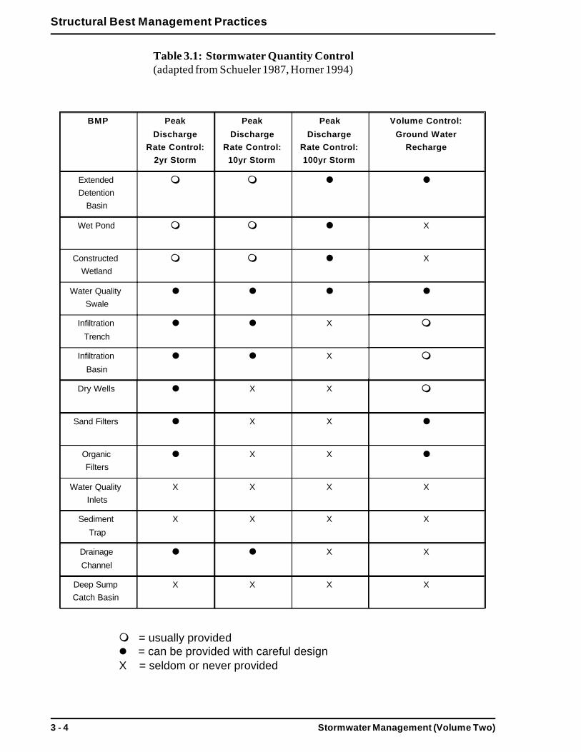
Controlling a site’s post-development hydrology can be achieved througha combination of streambank/channel erosion control (2-year stormevents), flood control (10 and 100-year storm events), and volume control(groundwater recharge). Table 3.1 indicates the types of quantity controlsprovided by specific BMPs. The following section, the BMP SizingProcess provides basic calculations to be used for compliance with theStormwater Management Standards.
Stormwater Management (Volume Two)3 - 4
Structural Best Management Practices
Table 3.1: Stormwater Quantity Control(adapted from Schueler 1987, Horner 1994)
= usually provided= can be provided with careful design
X = seldom or never provided
BMP Peak
DischargeRate Control:
2yr Storm
Peak
DischargeRate Control:10yr Storm
Peak
DischargeRate Control:100yr Storm
Volume Control:
Ground WaterRecharge
ExtendedDetention
Basin
Wet Pond X
ConstructedWetland
X
Water QualitySwale
Infiltration
Trench
X
Infiltration
Basin
X
Dry Wells X X
Sand Filters X X
OrganicFilters
X X
Water QualityInlets
X X X X
Sediment
Trap
X X X X
Drainage
Channel
X X
Deep SumpCatch Basin
X X X X

Stormwater Management (Volume Two) 3 - 5
Structural Best Management Practices
Stormwater Quality ManagementWhen designing stormwater management systems and screening BMPtechnologies to meet the water quality management standards, the engi-neer must answer the following questions:
Does the project affect a sensitive resource?
Based on existing and post-development conditions, what are the peakrunoff rates and volumes of stormwater to be treated for water quality?Is the water quality volume based on 0.5 inch or 1.0 inch of runofftimes the impervious area?
Based on existing and post-development conditions and soil types,what is the volume of stormwater to be recharged to groundwater?
Given the site conditions, which BMP types (e.g., detention, filtration)are most suitable?
What combination of BMP technologies and non-structural practicescan be utilized to achieve an 80% reduction of TSS loadings on anaverage annual basis?
Site Suitability/BMP SuitabilityIn choosing an effective BMP system, it is necessary to determine thetype(s) of BMP(s) technologies that are suitable for the characteristics ofthe site. Table 3.1 and Table 3.2 address a number of factors that should beconsidered when selecting BMPs. The basic site requirements for eachtechnology have been included in this handbook.
Site suitability is a major factor in choosing BMPs. Physical constraints ata site may include soil conditions, watershed size, depth to water table,depth to bedrock and slope. In some cases, a BMP may be eliminated asan option because of site constraints. Often, however, BMPs can bemodified or combined with other BMPs to adapt to site conditions and tocreate an efficient system capable of meeting the water quality and quan-tity standards.
The following sections briefly discuss the physical site conditions whichwill affect BMP selection.
Soil SuitabilityBasic soil requirements for each technology type have been included in thespecific technology sections in Chapter 3. Generally, detention/retentiontechnologies are applicable to a broad range of soil conditions, but wetponds may have difficulty maintaining water levels in very sandy soils.
Soil type is of particular importance to infiltration BMPs, and soils inMassachusetts may be too restrictive for wide application of infiltration

Stormwater Management (Volume Two)3 - 6
Structural Best Management Practices
practices. Specifically, infiltration technologies should not be applied inareas with soils exhibiting low permeability. This would exclude most “D”soil groups, as defined by the Natural Resources Conservation Service.Where infiltration technologies are planned, soils must be checked andadequate permeability confirmed.
Soil types and characteristics are less important to filtration technologies,as they do not need to maintain water levels or provide recharge. In somecases, where proper soils are present, filtration technologies may be usedto recharge a portion of the treated stormwater.
Drainage Area/Watershed To Be ServedThe size of the contributing area may be a limiting factor in selecting theappropriate BMP technology. Recommendations for appropriate contribut-ing watershed area requirements have been included in the discussion foreach technology. Through proper site planning, area constraints may oftenbe overcome.
Pond BMPs typically require large contributing drainage areas in order tofunction properly, while infiltration BMPs require smaller drainage areas.For technologies that require large contributing watersheds, additionaloffsite runoff may be routed to the BMP to increase flows. Conversely,portions of the total runoff can be routed to smaller individual BMPs toallow for the use of lower capacity BMPs. Keep in mind that use of anumber of individual BMPs in one drainage area may increase the mainte-nance and inspection requirements.
Depth to Water TableDepth to the seasonal high water table is an important factor for stormwa-ter technologies, especially infiltration BMPs. If the seasonal high watertable extends to within two feet of the bottom of an infiltration BMP, thesite is seldom considered suitable. The water table acts as an effectivebarrier to exfiltration through the BMP media and soils below and canreduce the ability of an infiltration BMP to drain properly. Contaminationpotential of the water table is of concern. Depending on soil conditions,depth to groundwater table is also an important factor in reducing the riskof microbial contamination.
For constructed wetlands and wet ponds, a water table at or near thesurface is desirable. Areas with high water tables are generally moreconducive to siting these types of detention/retention BMPs.
Depth to BedrockThe depth to bedrock (or other impermeable layers) is a consideration forfacilities which rely upon infiltration. The downward exfiltration of storm-water is impeded by bedrock that is near the surface, because infiltrationBMPs will not drain properly. A site is generally not suitable for infiltra-tion BMPs if the bedrock is within two feet of the bottom of the BMP.

Stormwater Management (Volume Two) 3 - 7
Structural Best Management Practices
Similarly, pond BMPs are not feasible if bedrock lies within the area thatmust be excavated to provide stormwater storage due to the expense ofexcavation.
SlopesThe slope of a site can restrict the type of BMP that can be used. Waterquality swales and infiltration trenches are not practical when slopesexceed 20%. To achieve water quality benefits, wet and dry swales anddrainage channels must not be sited on slopes greater than 5%. Wherethere are slopes, the BMPs must be very carefully designed to avoiderosion and flooding off site due to runoff discharges that bypass waterquality treatment BMPs.
Thermal EnhancementWet ponds and shallow marshes warm up rapidly in summer months.Warm water released from BMPs can be lethal to cold water aquaticorganisms. Unless design modifications such as the use of deep pools canmitigate for thermal impacts, these BMPs should not be considered for usein areas adjacent to designated cold water streams.
Proximity to Wells and FoundationsInfiltration of stormwater can cause seepage into foundations when BMPsare located too close to buildings; a ten foot setback is recommended.
Maintenance RequirementsBMPs must be maintained in order to operate properly. For this reason, theStormwater Management Standards require that all stormwater manage-ment facilities have an operation and maintenance plan. At a minimum,operation and maintenance plans should identify:
BMP(s) owner(s);
Party or parties responsible for operation and maintenance;
Source(s) of funding for continued operation and maintenance of theBMP(s);
Schedule for inspection and maintenance; and
Routine and infrequent maintenance tasks.
Too often, BMPs are constructed without plans or obligations for longterm maintenance. The maintenance requirements for BMP structuresmust be considered during the selection process, and the operation andmaintenance plan must be submitted for review along with the BMPdesign.
The basic maintenance requirements for each structural control have beenincluded in this chapter. For most BMPs, the maintenance requirements

Stormwater Management (Volume Two)3 - 8
Structural Best Management Practices
include visual tasks (e.g., inspection of sediment chambers/traps) andphysical upkeep tasks (e.g., sediment removal and disposal, and mowingof grassed swales).
For the developer, the most difficult part of developing a maintenance planmay be identifying a responsible party to perform and pay for the longterm maintenance of the BMP. The plan must clearly address the follow-ing BMP maintenance issues: how and when maintenance is to be per-formed, how and when inspections will be performed, and how these taskswill be financed.
For the above reasons, BMPs should be designed to minimize mainte-nance needs, wherever possible. Future maintenance problems should beanticipated and plans should be developed to alleviate them as much aspossible. Preventative design measures, such as the use of forebays to trapsediment inputs, can reduce the future maintenance costs and require-ments.
Public AcceptanceAesthetics are important in gaining acceptance of BMPs. BMPs can eitherenhance or degrade the amenities of the natural environment and theadjacent community. Careful planning, landscaping and maintenance canmake a BMP an asset to a site. Frequently, ownership and maintenanceresponsibilities for BMPs in new developments fall on adjacent propertyowners. If adjacent residents will be expected to pay for maintenance,education and acceptance of the BMP are necessary.
Cost EffectivenessProviding the most effective BMP system for the least cost should be thegoal of stormwater system designers. When comparing costs for variousBMPs, the designer must take into consideration the long term mainte-nance expenses, as well as the land acquisition, engineering and construc-tion costs. Table 3.2 summarizes the priority issues associated with BMPtechnology selection.
Note: This Table is for reference and summary only and is not intended tobe used without important narrative, guidelines, and requirements con-tained in this and other chapters.

Stormwater Management (Volume Two) 3 - 9
Structural Best Management Practices
Table 3.2: Comparison of Issues for BMP Selection (adapted from MWCOG, 1992)
BMP PollutantRemovalReliability
Longevity MaintenanceRequirement
Applicabilityto Sites
EnvironmentalConcerns
ComparativeCost
SpecialConsiderations
[Extended]Detention
Basin
Moderate 20+ years Low Widelyapplicable,
largerdrainage
areas (10+acres)
Possibledownstreamwarming; low
bacteria removal
Low toModerate
Available landarea; design
considerations;sediment forebay
Wet[Retention]
Pond
Moderate to high 20+ years Low tomoderate
Widelyapplicable,
largerdrainageareas (7+
acres)
Possibledownstreamwarming; low
bacteria removal
Moderate tohigh
Available landarea; design
considerations;sediment forebay
ConstructedStormwater
Wetland
Moderate to high 20+ years Low tomoderate
Widelyapplicable,
larger
drainageareas (7+
acres)
Possibledownstream
warming; wildlife
benefits
Marginallyhigher thanwet ponds
Available landarea; design
considerations;
sediment forebay
Water QualitySwale
Moderate 20+ years Low tomoderate
Widelyapplicable
Restricted use forhotspots
Low toModerate
Pretreatment;check dams;
careful design
InfiltrationTrench
Moderate to high High ratesof failure
within first 5years
High Highlyrestricted:small sites,
proper soils,depth to water
table and
bedrock,slopes
Potential forground watercontamination;
restricted use forhotspots
High;rehabilitationcosts can beconsiderable
Recommendedwith careful site
(soils) evaluationand pretreatment
InfiltrationBasin
Moderate High ratesof failure
within first 5years
High Highlyrestricted:small sites,
proper soils,depth to water
table andbedrock,slopes
Potential forground watercontamination;
restricted use forhotspots
Moderate;rehabilitationcosts can be
high
Not widelyrecommendeduntil longevity is
improved
Organic Filters Moderate to high 20+ years High Widely
applicable forsmall sites
Minor High; frequent
maintenance
Recommended
with carefuldesign;
pretreatment
Sand Filters Moderate to high 20+ years High Widelyapplicable for
small sites
Minor High; frequentmaintenance
Recommendedwith careful
design;pretreatment
Water QualityInlets
Low 20+ years Moderate tohigh
Small, highlyimperviousareas (< 2
acres)
Resuspension ofPAH loadings.
Disposal ofresiduals.
Moderate toHigh
Pretreatmenttechnology,
off-line
SedimentTrap [Forebay]
Low 20+ years Moderate Widelyapplicable aspretreatment
Resuspension ofaccumulated
sediment if notmaintained
Low tomoderate
Pretreatmenttechnology
DrainageChannel
Low 20+ years Low tomoderate
Low densitydevelopment
and roads
Erosion,resuspension
Low Pretreatmenttechnology, with
check dams
Deep Sump[Modified]
Catch Basin
Low 20+ years Moderate Small, highlyimperviousareas (< 2
acres)
Resuspension ofaccumulated
sediment if notmaintained
Low toModerate
Pretreatmenttechnology, design
modified withsump

Stormwater Management (Volume Two)3 - 10
Structural Best Management Practices
The BMP Sizing ProcessDesigning a stormwater management system requires precise sizing toensure that runoff is controlled at the project site. This section presents thesteps for designing a stormwater system that will comply with the Storm-water Management Standards. The following is a list of the types ofcalculations that are included to address both the water quality and volu-metric standards:
Water Quality and Recharge Calculations
I. The expected TSS removal with selected BMPs;
II. The volume of stormwater that is to be treated for water quality;
III. The volume of stormwater that is to be recharged into the groundwa-ter; and
Peak Discharge Rate Calculations
IV. The peak discharge rates from pre- and post-development conditions,and the volume of stormwater that must be retained onsite to control peakdischarge rates during specified storm events.
Water Quality and Recharge Calculations
NOTE: I. TSS Removal, II. Water Quality Volume, and III. Stormwa-ter RechargeThe following steps are used to select and size BMPs. The calculationsprovide the TSS removal rate of a stormwater management system, andthey also identify the necessary volumes to meet water quality and re-charge standards. Both the 0.5" and the 1.0" of impervious area runoffrules are referenced.
I. TSS Removal and BMP Selection
NOTE: The application of this standard has been simplified to estimate asite’s annual TSS load for compliance with this standard. The calculationshave been set up so that every site’s annual TSS load entering the firstBMP in the system is 1 (i.e. 100 %).
(1) For each drainage area, list the stormwater management BMPs andtheir order in the engineered system, beginning with the first BMPcollecting stormwater from the site. For example, pretreatment andconveyance BMPs will typically precede the removal BMPs. For eachdrainage area, list the BMPs in their respective order with their esti-mated TSS removal rates from the Stormwater Management Policy(Volume 1: Chapter 1).

Stormwater Management (Volume Two) 3 - 11
Structural Best Management Practices
(2) The TSS removal rates are not additive from one BMP to the next,instead the estimated removal rates must be applied consecutively asthe TSS load passes through each BMP technology. For the purposesof this calculation, and comply with the Stormwater ManagementStandards, represent the estimated annual TSS load as 1.00(i.e., 100 %).
(3) For each drainage area, apply the BMP estimated removal rate in theorder in which they occur in the stormwater system. The equation forthis calculation is:Final TSS Removal Rate = (TSS Average Annual Load * BMP1Removal Rate) + (Remaining TSS Load After Preceding BMP *BMP2 Removal Rate) + (Remaining TSS After Preceding BMP *BMP3 Removal Rate).
(4) After all of the BMPs in the initial stormwater system design havebeen accounted for and their estimated removal rates applied, the FinalTSS Removal Rate for each drainage area should be equal to or betterthan 80% (0.80). If the Final TSS Removal Rate is lower than 80% forany of the drainage areas, the system should be redesigned in order tomeet the Standards.
Note: It is imperative to compute the Final TSS Removal Rates for eachindividual drainage area. Rooftops, if serviced solely by their own BMPs,such as dry wells, should be considered a separate drainage system.
Example 1:A preliminary stormwater management system design calls for 8 deepsump catch basins to collect runoff from a small commercial parking lot.Stormwater will then be routed to a wet pond for final quantity and qualitycontrol. A rigorous parking lot sweeping plan will be followed Rooftoprunoff will be infiltrated through dry wells for recharge.
For parking lot and sidewalk drainage area:
Parking lot sweeping 10% (discretionary)Deep sump catch basins 25%Wet pond 80%
First, apply the parking lot sweeping credit:Average Annual Load (1.00) * BMP1 Removal Rate (0.10) = 0.10[TSS load estimated to be removed].0.90 of the TSS load remains (1.00 - 0.10).
Next, apply the deep sump catch basin removal:TSS load remaining (0.90) * BMP2 Removal Rate (0.25) = 0.225[TSS load estimated to be removed].0.675 of the TSS load remains (0.90 - 0.225).

Stormwater Management (Volume Two)3 - 12
Structural Best Management Practices
Then, apply the wet pond removal:TSS load remaining (0.675) * BMP3 Removal Rate (0.80) = 0.54[TSS load estimated to be removed].0.135 of the TSS load remains (0.675 - 0.54).
Lastly, the remaining TSS load is subtracted from the initial TSS load toderive the Final TSS Removal Rate: 1.00 - 0.135 = 0.865.The Final TSS Removal Rate can be estimated by adding sediment loadsremoved by each BMP. For this example, that would be: (0.10 + 0.225 +0.54) which totals 0.865 or 86.5%.
For this drainage area, this system as designed will remove an estimated86.5% of the annual TSS load and therefore will meet the TSS removalstandard if properly sized, designed, and maintained.
For the rooftop drainage area:
Dry well: 80% (uncontaminated)
Applying the dry well removal rate to the average annual load, results in80%: Average Annual Load (1.00) * BMP1 Removal Rate (0.80) = 0.80
Relying on dry wells to infiltrate uncontaminated rooftop runoff willremove an estimated 80% of the annual TSS load, and therefore thisrooftop system will meet the TSS removal standard. The volume of storm-water infiltrated through dry wells will also be applied to the rechargevolume requirement. This is explained below.
Example 2:
Proposed Stormwater Management System: The stormwater manage-ment system directs runoff from the parking and roadway areas to catchbasins with deep sumps (25% TSS removal). Drainage pipes convey thestormwater to sediment traps (25% TSS removal) and an extended deten-tion basin (60% TSS removal). Discharged runoff from the basin enters adrainage channel (25% TSS removal) with an outlet in the buffer zone.
TSS Removal Requirement: To meet Stormwater Management Standard#4, the system must remove 80 % (0.8 of 1) the average annual load ofTSS. To easily compute TSS removal, the average annual TSS loadentering the stormwater system from any site is set at 1 (i.e., 100 percent)of the total suspended solids.

Stormwater Management (Volume Two) 3 - 13
Structural Best Management Practices
Calculation of TSS Removal for the BMPs proposed:
STEP #1. Compute the TSS removed by each BMP, using the followingformula:(Removal rate %) X ( annual TSS load entering the BMP)
i. BMP1 - Catch basin with deep sump: (.25) X (1) = 25 % of TSSremoved by BMP 1
ii. BMP2 - Sediment trap: (.25) X ((1)(total TSS) - (.25)(TSS removed byBMP 1))
(.25) X (.75) = 18.7% TSS removed by BMP 2
iii. BMP3 - Extended detention basin (.60) X (.75-.187) (.60) X (.60) X (.56) =33.8 % TSS removed by BMP 3
iv. BMP 4 - Drainage channel (.25) X (.56-.338) (.25) X (.222) = 5.5 % of TSS removed.
STEP #2. Add together the amounts removed by each BMP to get the 80% TSS removal that is required in the Stormwater Management Standards.The formula is as follows:(TSS removed by BMP1) + (TSS removed by BMP2) + (TSS removedby BMP3) + (TSS removed by each additional BMP) = 80 % of thetotal annual TSS for the site.
i. (25 % removed) + (18.7 % removed) + (33.8% removed) + (5.5 %removed) = 83 % of TSS removed by the entire system. Since the 80 %removal is required, the stormwater system will achieve the TSS Manage-ment Standard when sized to handle either the required 0.5 inch or 1 inchof runoff.
II. Water Quality Volume
WQV = water quality volumeReV = recharge volumeI = total impervious area (including rooftop)Ir = rooftop impervious areaRR = rooftop runoff
(1) Compute total site area in acres (A).
(2) Compute total impervious area including roofs (I) in acres.

Stormwater Management (Volume Two)3 - 14
Structural Best Management Practices
(3) Find WQV:(a) Using 0.5" rule: WQV = 0.5" * I (acres)(b) Using 1.0" rule: WQV = 1.0" * I (acres)(c) WQV value will be in acre-inches.
(4) Convert to acre feet: WQV divided by 12 (inches).(a) WQV value now in acre-feet.
III. Stormwater Recharge
(5) Compute areas of different Hydrologic Group soils and the area ofimpervious surfaces overlying these soil types in acres: (Note thatHydrologic Group D soils are omitted.)
(a) Find total area of Hydrologic Group A soils on site = Aa(acres)
(b) Find total impervious area overlying A soils = Ia (acres)(c) Find total area of Hydrologic Group B soils on site = Ab
(acres)(d) Find total impervious area overlying B soils = Ib (acres)(e) Find total area of Hydrologic Group C soils on site = Ac
(acres)(f) Find total impervious area overlying C soils = Ic (acres)
(6) Compute the recharge volume required for each Hydrologic Groupsoil:
(a) Find recharge volume for A soils (ReVa): ReVa = Ia *0.40
(b) Find recharge volume for B soils (ReVb): ReVb = Ib *0.25
(c) Find recharge volume for C soils (ReVc): ReVc = Ic * 0.10(d) Total recharge volume: ReV = ReVa + ReVb = ReVc
(acre-inches)(e) Convert to acre-feet: ReV divided by 12
(7) Compute rooftop runoff (RR):(a) Compute rooftop area in acres (Ir)(b) Rooftop runoff (RR)
(0.5" rule) RR = Ir * 0.5"(1.0" rule) RR = Ir * 1.0"
(c) Covert to acre-feet: RR divided by 12
(8) Identify how much of recharge volume (ReV) requirement can be metby infiltrating rooftop runoff (RR) [ReV - RR] and remaining rechargevolume (if any) to be infiltrated. [NOTE: The remaining volume to berecharged should be runoff that has been conveyed through waterquality BMPs.]

Stormwater Management (Volume Two) 3 - 15
Structural Best Management Practices
(9) Subtract the rooftop runoff volume (RR) from the total water qualityvolume (WQV) to get the volume of stormwater that must be treatedfor water quality.
Peak Discharge Rate Calculations
To Calculate Peak Discharge Rates and Volumes of Stormwater toRetain OnsiteThe following is a list of the basic steps to be taken in order to calculatethe peak discharge rates from pre- and post-development conditions andthe volume of stormwater that must be retained onsite to control for peakdischarge rates from specified storms. In many cases, engineers will utilizemodels to conduct these calculations. The NRCS TR-55 is widely uti-lized, and many of the steps below have been automated with a com-puter program and requires only data input. For a more detailedaccount refer to the NRCS publication, Urban Hydrology for SmallWatersheds.
Steps for the Peak Discharge Rate(calculated for pre- and post-development):
Am = contributing drainage area to siteRCN = runoff curve numberTc = time of concentrationP = 24-hour site rainfall from specified eventIa = initial abstractionQu = unit peak dischargeQ = site runoffFp = pond and wetland adjustment factorQp = peak discharge
(1) Calculate the contributing drainage area to site (Am).(a) Use USGS topographic maps and site visits.
(2) Calculate the Runoff Curve Number (RCN).(a) Use NRCS maps and site visits to determine soils and types
within Am.(b) Determine the Hydrologic Soils Group (HSG) for the soils
identified in (a).(c) Determine land use, cover type, treatment, hydrologic
condition, % impervious, and % connected/unconnectedimpervious area ratio.
(d) Develop a composite land use and HSG map from theinformation in (a)-(c).
(d) Select RCNs from appropriate charts (TR-55).(e) Compute a weighted RCN for the entire drainage area.

Stormwater Management (Volume Two)3 - 16
Structural Best Management Practices
(3) Calculate the site Time of Concentration (Tc).(a) Determine sheet flow, shallow concentrated flow and
channel flow from the most hydraulically distant point inthe drainage area to the drainage discharge point at theboundary site.
(4) Determine rainfall distribution type:(a) Use Type III for Massachusetts.
(5) Determine percentage of ponds and wetlands in the drainage area:(a) Measure from USGS topographic sheet.
(6) Select design frequency storms to be evaluated:(a) 2-year, 10- year, 100-year as in Standards and Basis for
Evaluations.(b) Other designs storms commonly evaluated are the 25-year
and the 50-year.
(7) Determine the 24-hour site rainfall amounts (P) for each design storm.(a) From US Weather Bureau charts and listed in TR-55.
(8) Determine Initial Abstraction (Ia). Initial abstraction is a representationof interception, initial infiltration, surface depression storage, andevapotranspiration.
(a) This value obtained from TR-55 chart based on the site’sRCN.
(9) Calculate the Ia/P ratio.
(10) Determine the Unit Peak Discharge (Qu).(a) This value obtained from TR-55 chart based on the Ia/P
ratio and the Tc.
(11) Determine the site runoff (Q).(a) This value obtained from TR-55 based on the RCN and the
rainfall P.
(12) Determine the Pond and Wetland Adjustment Factor (Fp).(a) This value obtained from TR-55 chart based on percentage
of ponds and wetlands in Am.
(13) Calculate the final Peak Discharge Rate (Qp) for the site.(a) Qp = (Qu) * (Am) * (Q) * (Fp)(b) Calculate pre-development Qp.
Calculate post-development Qp.

Stormwater Management (Volume Two) 3 - 17
Structural Best Management Practices
IV. Steps to Calculate Volume to Store Onsite for Control of PeakDischarge Rates:
Qo = peak outflow from detention systemQi = peak inflow to detention systemVs = volume of storage for detention systemVr = volume of runoff
(14) Calculate the contributing drainage area (Am).(a) Use value from (1) above.
(15) Determine rainfall distribution type.(a) Use Type III for Massachusetts.
(16) Select design frequency storms to be evaluated:(a) 2-year, 10-year, 100-year as in Standards and Basis for
Evaluations.(b) Other designs storms commonly evaluated are the 25-year
and the 50-year.
(17) Determine the peak inflow (Qi) to the water quantity facility(BMP).
(a) This value is typically the post-development peak dischargerate (Qp) from (12) above.
(18) Determine the peak outflow (Qo) from the water quantity facility(BMP).(a) This value is the pre-development peak discharge (Qp)
from (12) above.
(19) Calculate the outflow to inflow ratio (Qo/Qi).
(20) Find the volume of storage to volume of runoff (Vs/Vr) ratio.(a) This curve value obtained from TR-55 graph/chart based on
the Qo/Qi ratio and the rainfall distribution type. The Vs/Vrratio will be a value between 0.1 and 0.6.
(21) Determine the site runoff (Q).(a) Use value from (10) above.
(22) Calculate the runoff volume (Vr).(a) Vr = (Q) * (Am)

Stormwater Management (Volume Two)3 - 18
Structural Best Management Practices
(23) Calculate the storage volume (Vs) to be allocated for the waterquantity facility (BMP). This is the volume that must be storedonsite to maintain the peak discharge rates from the specifiedfrequency storm events.(a) Vs = (Vr) * (Vs/Vr) [Vs/Vr from (19) above].
(24) Repeat steps (16)-(23) to determine the required storage volumesfor the design storm frequencies from (6).
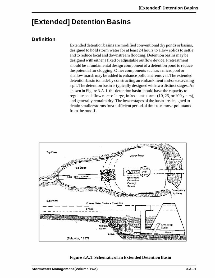
Stormwater Management (Volume Two) 3.A - 1
[Extended] Detention Basins
[Extended] Detention Basins
DefinitionExtended detention basins are modified conventional dry ponds or basins,designed to hold storm water for at least 24 hours to allow solids to settleand to reduce local and downstream flooding. Detention basins may bedesigned with either a fixed or adjustable outflow device. Pretreatmentshould be a fundamental design component of a detention pond to reducethe potential for clogging. Other components such as a micropool orshallow marsh may be added to enhance pollutant removal. The extendeddetention basin is made by constructing an embankment and/or excavatinga pit. The detention basin is typically designed with two distinct stages. Asshown in Figure 3.A.1, the detention basin should have the capacity toregulate peak flow rates of large, infrequent storms (10, 25, or 100 years),and generally remains dry. The lower stages of the basin are designed todetain smaller storms for a sufficient period of time to remove pollutantsfrom the runoff.
Figure 3.A.1: Schematic of an Extended Detention Basin

Stormwater Management (Volume Two)3.A - 2
[Extended] Detention Basins
PurposeTo reduce peak discharge rates and reduce occurrence of erosivedownstream flooding.
To remove particulate pollutants from runoff.
AdvantagesLeast costly BMP that controls both stormwater quantity and quality.
Good retrofitting option for existing basins.
Can remove significant levels of sediment and sorbed pollutants.
Potential for beneficial terrestrial and aquatic habitat.
Less potential for hazards than deeper permanent pools.
Disadvantages Infiltration and groundwater recharge is negligible, resulting in minimal
runoff volume reduction.
Removal of soluble pollutants is minimal.
Requires relatively large land area.
Moderate to high maintenance requirements.
Potential contributor to downstream warming.
Sediment can be resuspended after large storms if not removed.
ApplicabilityGenerally, detention basins are not practical if the contributing watershedarea is less than ten acres. Four acres of drainage area are recommendedfor each acre-foot of storage in the basin.
Detention basins can be used at residential, commercial and industrial sites.Because they have a limited capability for removing soluble pollutants,detention basins are more suitable for commercial applications where thereare high loadings of sediment, metals and hydrocarbons. At low densityresidential areas, where soluble nutrients from pesticides and fertilizers maybe a concern, the use of detention basins alone should be considered verycarefully. Combining detention basins with a shallow marsh system or otherBMPs may be more appropriate.
Existing basins can be retrofitted as detention basins by modifying theoutlet structure, at a relatively low cost. Because of the land requirements

Stormwater Management (Volume Two) 3.A - 3
[Extended] Detention Basins
for detention basins, they are not feasible at sites where land costs or spaceis at a premium, however. Soils, depth to bedrock, and depth to water tableshould be investigated before designing a detention basin for a site. At siteswhere bedrock is close to the surface, high excavation costs may makedetention basins infeasible. If soils on site are relatively impermeable, suchas a soil group D, (as defined by the Natural Resource ConservationService (NRCS)), a detention basin may experience problems with standingwater. In this case, the use of a wet [retention] pond may be more appro-priate. If the water table is within two feet of the bottom of the detentionbasin, it can also create problems with standing water. On the other hand, ifthe soils are highly permeable, such as well drained sandy and gravely soils(NRCS Soil Group A), it will be difficult to establish a shallow marshcomponent in the basin.
EffectivenessPollutant removal rates and design requirements for detention basins are inthe Stormwater Management Policy (Volume 1, Chapter 1) . The primarypollutant removal mechanism in dry detention basins is settling; therefore,the degree of pollutant removal is dependent upon whether the pollutant isin the particulate or soluble form. Limited removal can be expected forsoluble pollutants, while high removal rates can be expected for particulatepollutants. Removal of soluble pollutants can be enhanced in the lowerstage of the basin, if it is maintained as a shallow wetland, where naturalbiological removal processes occur. The degree of removal by such wet-lands appears to be dependent upon wetland size in relation to loading.
When designed properly, detention basins are effective in reducing pollut-ant loads and controlling post-development peak discharge rates. Detentionbasins can be used to meet the Stormwater Management Standards. Use ofdetention basins will not, however, reduce post-development increases inrunoff volume.
Planning ConsiderationsSoils, depth to bedrock and depth to water table should be checked beforedesigning a detention basin. At sites where bedrock is close to the surface,high excavation costs may make detention basins infeasible. If soils on siteare relatively impermeable, a detention basin may experience problems withstanding water. If the water table is within two feet of the bottom of adetention basin, it can also have problems with standing water. If the soilsare highly permeable, it will be difficult to establish a shallow marsh com-ponent in the basin, unless a liner is used.
Maximum depth of the detention basins may range from 3 to 12 feet. Thedepth of the basin may be limited by groundwater conditions or by soils.Detention basins should be above normal groundwater elevation (i.e.should not intercept groundwater). The effects of seepage on the basinneed to be investigated, if the basin is to intercept the groundwater table.

Stormwater Management (Volume Two)3.A - 4
[Extended] Detention Basins
To be effective in reducing peak runoff rates, the basin must be locatedwhere it can intercept most of the runoff from the site. Usually, this loca-tion is found at the lowest elevation of the site where freshwater wetlandsare frequently found. The effects of a detention basin on wetland resourcesmust be examined. Altered wetland resources must be mitigated accordingto local, state and federal regulations. Under the requirements of the state’s401 Water Quality Certification regulations, no detention ponds or otherstormwater controls may be located in natural wetlands.
Embankments, or dams, created to store more than 15 acre-feet, or that aremore than 6 feet in height, are under the jurisdiction of the state Office ofDam Safety and are subject to regulation.
DesignSee the following document for complete design references: Design ofStormwater Pond Systems. 1996. Schueler. Center for Watershed Protec-tion.
Detention basin design must account for large, infrequent storm events forrunoff quantity control, as well as small, frequent storm events for runoffquality control.
Typically, the first flush of runoff contains the highest concentrations ofpollutants. Thus, detention basins should be designed to maximize thedetention time for the most frequent storms. Routing calculations for arange of storms should provide the designer with the optimal basin size.Generally, most particulates settle within the first 12 hours of detention;however, additional time is required to settle finer particulates. Twenty fourhours is the minimum detention time necessary for optimal pollutant re-moval.
The design should provide an average of 24 hours detention time for theexpected storm events in each year. This can be achieved by setting themaximum detention time for the greatest runoff volume at approximately40 hours. The average detention time for very small storms should be noless than 6 hours. By incorporating multiple exit points at different eleva-tions, the designer can attain longer detention times for smaller storms.
In determining the size of the basin, the critical parameters are the storagecapacity and the maximum rate of runoff released from the basin. Thestorage volume can be estimated in a number of ways. A typical approachis to limit the peak rate outflow to some predetermined level, such as thepre-development peak level.
To maximize sedimentation, the detention basin should be designed tolengthen the flow path, thereby increasing detention time. To maximize thedetention time, the inflow points should be as far from the outlet structureas possible. Long, narrow configurations, with length to width ratios of 2:1

Stormwater Management (Volume Two) 3.A - 5
[Extended] Detention Basins
or 3:1, are recommended. Shallow basins with large surface areas alsoprovide better removal efficiencies than small deep basins.
By reducing inflow velocity, detention time is lengthened, resuspension ofsettled pollutants is minimized, and sedimentation of incoming runoff isenhanced. All inflow points should be designed with riprap or other energydissipators, such as a baffle below the inflow structure. A sediment forebaywill enhance the removal rates of particulates, decrease the velocity ofincoming runoff, and reduce the potential for failure due to clogging.Sediment forebays should be designed for ease of maintenance. Hardbottom forebays make sediment removal easier, and forebays should beaccessible by heavy machinery, if necessary.
A low flow channel routes the last remaining runoff, dry weather flow andgroundwater to the outlet, which should be installed in the upper stage ofthe basin to ensure that the basin drys out completely. Pervious or impervi-ous channel lining may be used. A pervious lining allows interaction of therunoff with the soil and grass, resulting in increased sorption of pollutants.Design velocities in pervious low flow channels should be high enough toprevent sedimentation and low enough to prevent scouring and erosion. Nominimum low flow channel velocity is needed if a forebay is utilized priorto the low flow channel. The maximum flow velocity (which should be setat the 2-year peak discharge rate) is dependent on the nature of the mate-rial used to line the channel
Impervious channels are simple to construct, easy to maintain, and emptycompletely after a storm event. Impervious channels can be undermined byrunoff flow and differential settling if not constructed and maintainedproperly. The top of the impervious channel lining should be located at orbelow the level of the adjacent grassed areas to ensure thorough drainageof these areas. When designing the channels, settlement of the lining andthe adjacent areas must be taken into account; the potential for frostimpacts on the lining should also be considered. Impervious lining shouldbe provided with broken stone foundations and weep holes. The potentialfor erosion or scour along the edges of the lining caused by bankfull veloci-ties must be taken into consideration, when designing a channel. A lowoutflow discharge rate should be maintained at the downstream end of thechannel to ensure sufficient treatment of runoff, which backs up and over-flows onto the grassed basin bottom.
Low flow underdrains, connected to the principal outlet structure or otherdownstream discharge point, are recommended to promote thoroughdrying of the channel and the basin bottom. Depth of the low flow channelmust be taken into account when preparing the final bottom grading plan.
Establishing wetland vegetation in a shallow marsh component or on anaquatic bench in the lower stage of the detention basin will enhance re-moval of soluble nutrients, increase sediment trapping, prevent sediment
Stormwater Management (Volume Two)3.A - 6
[Extended] Detention Basins
resuspension, and provide wildlife and waterfowl habitat. Proper soils andsurface or groundwater depth are needed to maintain wetland vegetation.For additional information on establishing wetlands vegetation see Section3.C.
Detention basin side slopes should be no steeper than 3:1, and the use ofintermittent benches is recommended both for vegetation and for safety.Flatter slopes help to prevent erosion of the banks during larger storms,make routine bank maintenance tasks (such as mowing) easier, and allowaccess to the basin.
A multi-stage outlet structure is necessary to provide an adequate level ofwater quality and flood control. To meet the water quantity control stan-dards, the required design storm runoff rates should be used as outletrelease rates. For water quality control, the release rate will vary with thedesign storm selected. When used in conjunction with other BMPs to meetthe water quality control standards, the release rate for the detention basinmay be designed for a smaller storm (i.e., 1-year). For detention basinswith shallow marshes or permanent pools, the lowest stage outlet must beplaced to allow for the maintenance of a permanent pool of water.
The type of outlet structure will depend on factors, such as the type ofspillway, basin configuration and extended detention outflow rate. Theoutlet must be designed to control the outflow rate without clogging. Theoutlet structure should be located in the embankment for maintenance,access, safety and aesthetics. The outlet should be designed to facilitatemaintenance; the vital parts of the structures should be accessible duringnormal maintenance and emergency situations. It also should contain adrain-down valve for complete detention basin draining within 24 hours.
To prevent scour at the outlet, a flow transition structure, such as a linedapron or plunge pad, is needed to absorb the initial impact of the flow andreduce the velocity to a level that will not erode the receiving channel orarea.
Embankments and spillways should be designed in conformance with thestate regulations for Dam Safety (302 CMR 10.00). All detention basinsmust have an emergency spillway capable of bypassing runoff from largestorms without damaging to the impounding structure.
An access for maintenance, minimum width of 10 feet and a maximumslope of 5:1, must be provided by public or private right-of-way. Thisaccess should extend to the forebay, safety bench and outflow structure,and should never cross the emergency spillway, unless the spillway hasbeen designed for that purpose.
Vegetative buffers around the perimeter of the basin are recommended forerosion control and additional sediment and nutrient removal.

Stormwater Management (Volume Two) 3.A - 7
[Extended] Detention Basins
MaintenanceDetention basins should be inspected at least once per year to ensure thatthe basins are operating as intended. Inspections conducted at intervalsduring and after the storm will help to determine if the basin is meeting theexpected detention times. The outlet structure should be inspected forevidence of clogging or outflow release velocities that are greater thandesign flow. Potential problems that should be checked include: subsidence,erosion, cracking or tree growth on the embankment; damage to theemergency spillway; sediment accumulation around the outlet; inadequacyof the inlet/outlet channel erosion control measures; changes in the condi-tion of the pilot channel; and erosion within the basin and banks. Anynecessary repairs should be made immediately. During inspections, changesto the detention basin or the contributing watershed should be noted, asthese may affect basin performance.
The upper-stage, side slopes, embankment, and emergency spillway shouldbe mowed at least twice per year. Trash and debris should also be removedat this time.
Sediment should be removed from the basin as necessary, and at least onceevery 5 years. Providing for an on-site sediment disposal area will reducethe overall sediment removal costs.
Summary: Guidelines for [Extended] Detention Basins
Site CriteriaFor each acre-foot of storage in a detention basin, four acres of drainage area are recommended. The contributing drainage area to anyindividual detention basin should be at least 20 acres if a permanentpool or wetland is part of the design.
Soils, depth to bedrock and depth to water table at the proposedlocation of the detention basin must be investigated. Site conditionsmust be suited to the siting of the detention basin:
-- Poorly drained soils may result in standing water.-- Bedrock close to surface may prevent excavation.
The following minimum setback requirements should apply to detentionbasin installations:
-- Distance from a septic system leach field - 50 feet.-- Distance from a septic system tank - 25 feet.-- Distance from a private well - 50 feet-- Distance from the property line -10 feet.

Stormwater Management (Volume Two)3.A - 8
[Extended] Detention Basins
Design CriteriaDesign of the detention basin should target a 24 hour average detentiontime for the entire spectrum of storm events in each year. The longestdetention time for the maximum runoff volume should be set at ap-proximately 40 hours. The average detention time for very small stormsshould be no less than 6 hours.
The size of the detention basin is based on the volume of runoff thatneeds to be detained over a specific period of time.
The original design of the detention basin should account for gradualaccumulation of sediment.
Distance between inlets and outlets should be as great as possible tolengthen the flow path and increase detention time.
Detention basins should be wedge-shaped, if possible, narrowest at theinlet and widest at the outlet.
Inflow points should be designed with energy dissipators to reduceinflow velocity.
The inlet should be designed with a forebay or settling zone to trapcoarse sediments.
Detention basin side slopes should be no steeper than 3:1.
A multi-stage outlet structure is necessary to provide an adequate levelof water quality and flood control. For detention basins with shallowmarshes or permanent micropools, the lowest stage orifice must beplaced to allow for the maintenance of a permanent pool of water.
The use of a shallow marsh with the detention basin will enhance thepollutant removal performance of the basin. At least 6 to 12 inches ofwater depth are needed for optimum wetland vegetation growth.
A low flow channel should be installed in the top stage of the basin toensure that the basin drys out completely.
The type of outlet structure used will depend on factors such as thetype of spillway, basin configuration, and extended detention outflowrate. The outlet must control the outflow rate effectively, and also beprotected from clogging.
The outlet structure should be designed to facilitate maintenance;structures should be accessible to maintenance personnel during normaland emergency conditions.

Stormwater Management (Volume Two) 3.A - 9
[Extended] Detention Basins
The outlet structure should contain a drain-down valve which willallow complete draining of the detention basin within 24 hours foremergency purposes or routine maintenance.
Embankments and spillways should be designed in conformance withthe state dam safety regulations and criteria. All detention basins musthave an emergency spillway capable of bypassing runoff from largestorms without damaging the impounding structure.
To prevent scour at the outlet, a flow transition structure, such as alined apron or plunge pad, is needed to absorb the initial impact of theflow, and reduce the velocity to a level that will not erode the receivingchannel or area.
An access for maintenance, minimum width of 10 feet and a maximumslope of 15%, must be provided by public or private right-of-way. Thisaccess should never cross the emergency spillway, unless the spillwayhas been designed for that purpose.
Maintenance CriteriaMaintenance is required for the proper operation of detention basins;plans for detention basins should identify owners, parties responsiblefor maintenance, and an inspection and maintenance schedule.
Detention basins should be inspected at least once per year to ensurethat the basin is operating as intended. Inspections should be conductedduring wet weather to determine if the basin is meeting the targeteddetention times.
At least twice during the growing season the upper-stage, side slopes,embankment, and emergency spillway should be mowed, and accumu-lated trash and debris removed.
Sediment should be removed from the basin as necessary, and at leastonce every 10 years.
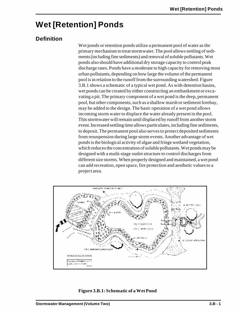
Stormwater Management (Volume Two) 3.B - 1
Wet [Retention] Ponds
Wet [Retention] Ponds
DefinitionWet ponds or retention ponds utilize a permanent pool of water as theprimary mechanism to treat stormwater. The pool allows settling of sedi-ments (including fine sediments) and removal of soluble pollutants. Wetponds also should have additional dry storage capacity to control peakdischarge rates. Ponds have a moderate to high capacity for removing mosturban pollutants, depending on how large the volume of the permanentpool is in relation to the runoff from the surrounding watershed. Figure3.B.1 shows a schematic of a typical wet pond. As with detention basins,wet ponds can be created by either constructing an embankment or exca-vating a pit. The primary component of a wet pond is the deep, permanentpool, but other components, such as a shallow marsh or sediment forebay,may be added to the design. The basic operation of a wet pond allowsincoming storm water to displace the water already present in the pool.This stormwater will remain until displaced by runoff from another stormevent. Increased settling time allows particulates, including fine sediments,to deposit. The permanent pool also serves to protect deposited sedimentsfrom resuspension during large storm events. Another advantage of wetponds is the biological activity of algae and fringe wetland vegetation,which reduces the concentration of soluble pollutants. Wet ponds may bedesigned with a multi-stage outlet structure to control discharges fromdifferent size storms. When properly designed and maintained, a wet pondcan add recreation, open space, fire protection and aesthetic values to aproject area.
Figure 3.B.1: Schematic of a Wet Pond
STORAGE ALLOCATION:

Stormwater Management (Volume Two)3.B - 2
Wet [Retention] Ponds
PurposeTo remove particulate pollutants from runoff.
To reduce peak discharge and the occurrence of erosive downstreamflows. [Note: Wet ponds must be designed with detention storagecapacity to meet this goal]
AdvantagesCapable of removing both solid and soluble pollutants.
Aesthetically pleasing BMP.
Can increase adjacent property values when planned and sited properly.
Pond sediment removal schedule is generally less frequent than forother BMPs.
DisadvantagesMore costly than extended detention basins.
Larger storage volumes for the permanent pool and flood controlrequire more land area.
Infiltration and groundwater recharge is minimal, therefore runoffvolume control is negligible.
Requires relatively large land area.
Moderate to high maintenance requirements.
Potential for contributing to downstream warming.
ApplicabilityGenerally, dry weather base flow and/or large contributing drainage areasare required to maintain pool elevations. Minimum contributing drainagearea should be at least 10 acres, but not more than one square mile. Siteswith less than 10 acres of contributing drainage area may be suitable ifsufficient groundwater flow is available.
Wet ponds can be used at residential, commercial and industrial sites. Sincewet ponds have the capability of removing soluble pollutants, they aresuitable for sites where nutrient loadings are expected to be high.
As for other stormwater BMPs, soils, depth to bedrock, and depth to watertable must be investigated before designing a wet pond. At sites wherebedrock is close to the surface, high excavation costs may make wet pondsinfeasible. If the soils on site are relatively permeable or well drained, such

Stormwater Management (Volume Two) 3.B - 3
Wet [Retention] Ponds
as a soil type in Hydrologic Group A (as defined by the Natural ResourceConservation Service), it will be difficult to maintain a permanent pool. Inthis situation, it may be necessary to line the bottom of the wet pond toreduce infiltration.
EffectivenessTable 5.2 shows the range of removal efficiencies for wet ponds. When thewet pond is well planned, designed, constructed, and maintained, pollutantloading reduction should be at the high end of the reported values. Wetponds can be used to meet the Stormwater Management Standards.
If designed with proper storage capacities, wet ponds may be effective incontrolling post-development peak discharge rates at desired pre-develop-ment levels. The highest degree of flood control can be attained whenmultiple design storms are controlled. The upper stages of wet pondsshould be designed to provide temporary storage of larger storms (i.e., 10,25, and 100-year storms). Wet ponds are generally ineffective in controllingthe post-development increase in runoff volume, although some infiltrationdoes occur, as well as evaporation in summer months.
Planning ConsiderationsSoils and depth to bedrock must be checked before designing a wet pondfor a site. At sites where bedrock is close to the surface, high excavationcosts may make wet ponds infeasible. If the soils are permeable (A and Bsoils), heavy drawdown of the pond may occur during dry periods. In thesesituations, the potential for drawdown may be minimized by installing aliner at the bottom of the pond or by compacting the pond soils. Specifica-tions for pond liner materials are as follows (in order of decreasing costs):
6 inch claypolyvinyl linerbentontite6 inches of silt loam or finer.
To be effective in reducing peak runoff rates, the pond must be locatedwhere it can intercept most of the runoff from the site. Usually this locationis found at the lowest elevation of the site where freshwater wetlands aremost often located. The effects of the wet pond on wetland resources mustbe examined. Altered wetland resources must be mitigated according tolocal, state, and federal regulations.
Embankments or dams created to store more than 15 acre-feet, or that aremore than 6 feet in height, are under the jurisdiction of the state Office ofDam Safety and should be constructed, inspected and maintained accordingto agency guidelines.
Stormwater Management (Volume Two)3.B - 4
Wet [Retention] Ponds
DesignSee the following for complete design references:
Wet Extended Detention Pond Design: Step by Step Design. 1995. Calytor.Center for Watershed Protection.
Design of stormwater pond systems. 1996. Schueler. Center for WatershedProtection.
Volume and geometry are the critical parameters in a wet pond designbecause of the relationship of the volume in the permanent pool to thecontributing runoff volume directly affects pollutant removal rates. Gener-ally, bigger is better; however, after a certain threshold size, increasing thepool size results in only marginal increases in pollutant removal. To achievea meaningful reduction in pollutant loading, the ratio of pool volume torunoff volume must be greater than 2, and preferably 4. The pool: runoffratio of 4 or greater is recommended for the control of nutrient pollution.A pool:runoff ratio of 4 equates to a hydrologic residence time of approxi-mately two weeks, and is estimated to achieve about 85-90% sedimentremoval.
For each acre-foot of storage in an wet pond, 4 acres of drainage area arerecommended. Generally, dry weather base flow and/or large contributingdrainage areas are required to maintain pool elevations. Minimum contrib-uting drainage areas should be at least of 10 acres, but should not exceedone square mile. Sites with less than ten acres of contributing drainage areamay be suitable if sufficient groundwater flow is available.
Pool depth is an important design factor, especially for sediment deposi-tion. An average pool depth of 3 to 6 feet is recommended. Settling col-umn studies and modeling analyses have shown that shallow ponds havehigher solids removal than deeper ones. However, resuspension of settledmaterials by wind may be a problem in shallow ponds that are less than 2feet in depth. Depths in excess of 8 feet may result in thermal stratification.Stratified pools tend to become anoxic (low or no oxygen) more often thanshallower ponds.
It is desirable to vary depths throughout the pond. Intermittent benchesaround the perimeter of the pond are recommended for safety and topromote vegetation. The safety bench should be designed to be at least 10feet wide and located above normal pool elevations. The aquatic benchshould be a minimum of ten feet wide and depths of 12-18 inches should bemaintained at normal elevations to support aquatic vegetation. Shallowdepths near the inlet will concentrate sediment deposition in a smaller,more accessible area. Deeper depths near the outlet will yield coolerbottom water discharges that may mitigate downstream thermal effects.

Stormwater Management (Volume Two) 3.B - 5
Wet [Retention] Ponds
A minimum pool surface area of 0.25 acres is recommended. Performanceof the wet pond may be enhanced by enlarging the surface area to increasevolume, as opposed to deepening the pool. This may result in higher watertemperatures and increased evaporation rates, however.
The original design of wet pond depths and volumes should take intoaccount the gradual accumulation of sediment. Accumulation of sedimentin the pool will result in a loss of volume and a reduction in pollutantremoval efficiency.
As for detention basins, the use of a sediment forebay is highly recom-mended. Forebays serve to trap sediments before the runoff enters theprimary pool, effectively enhancing removal rates and minimizing long termoperation and maintenance problems. Periodic sediment removal from theforebay is easier and less costly than removal from the wet pond pool.Sediment forebays should be designed for ease of maintenance. Hardbottom forebays make sediment removal easier, and forebays should beaccessible by heavy machinery, if necessary.
To avoid reducing the pollutant removal capability and to maximize traveldistance, the inflow points should be as far from the outlet structure aspossible. To maximize stormwater contact and retention time in the pool, alength to width ratio of 3:1 is recommended.
The invert elevation of the inlet pipe should be set at or below the surfaceof the permanent pool; preferably, within one foot of the pool. Pipes whichdischarge above the pool can erode the banks and side slopes. All inflowpoints should be designed with riprap or other energy dissipators to reducethe inflow velocity.
Establishing wetland vegetation on the aquatic bench will enhance removalof soluble nutrients, enhance sediment trapping, prevent sedimentresuspension, provide wildlife and waterfowl habitat and conceal trash anddebris that may accumulate near the outlet. Six to eighteen inches of waterdepth are needed for wetland vegetation growth. Additional information onplanting wetlands vegetation is in Section 3.C, Constructed StormwaterWetlands.
Slopes of the pools should be no steeper than 3:1. Flatter slopes help toprevent erosion of the banks during larger storms and make routine bankmaintenance tasks, such as mowing, easier. Flat slopes also provide forpublic safety, and allow easier access. Furthermore, the sides of the poolthat extend below the safety and aquatic benches to the bottom of the poolshould be at a slope that will remain stable, usually no steeper than 2:1(horizontal: vertical).
The invert of the wet pond outlet pipe should be designed to conveystormwater from approximately one foot below the pool surface and to
Stormwater Management (Volume Two)3.B - 6
Wet [Retention] Ponds
discharge into the riser in the pond embankment. To prevent clogging,trash racks or hoods should be installed on the riser. To facilitate access formaintenance, the riser should be installed within the embankment. Anti-seep collars or filter and drainage diaphragms should be installed on theoutlet barrel to prevent seepage and pipe failure.
The outlet structure should be designed to facilitate maintenance; the vitalparts of the structures should be accessible to maintenance personnelduring normal and emergency conditions. A bottom drain pipe should beinstalled for complete draining of the wet pond in case of emergencies orroutine maintenance. Both the outlet pipe and the bottom drain pipe shouldbe fitted with adjustable valves at the outer end of the outlet. These valvescan be used to adjust the detention time, if necessary. To prevent scour atthe outlet, a flow transition structure, such as a lined apron or plunge pad,is needed to absorb the initial impact of the flow and reduce the velocity toa level that will not erode the receiving channel or area.
Embankments and spillways should be designed in conformance with thestate guidelines for Dam Safety. All wet ponds must have an emergencyspillway capable of bypassing runoff from large storms without damagingthe impounding structure.
An access for maintenance, with a minimum width of 10 feet and a maxi-mum slope of 15%, must be provided by public or private right-of-way.This access should extend to the forebay, safety bench, and outflow struc-ture and should never cross the emergency spillway, unless the spillway hasbeen designed for that purpose.
Vegetative buffers around the perimeter of the wet pond are recommendedfor erosion control and additional sediment and nutrient removal.
MaintenanceWet ponds should be inspected at least once per year to ensure that it isoperating as designed. The outlet structure should be inspected for evi-dence of clogging or too rapid an outflow release. Potential problems thatshould be checked include: subsidence, erosion, cracking or tree growth onthe embankment, damage to the emergency spillway, sediment accumula-tion around the outlet, inadequacy of the inlet/outlet channel erosioncontrol measures, changes in the condition of the pilot channel and erosionwithin the pond and banks. Any necessary repairs should be made immedi-ately. During inspections, changes to the wet pond or the contributingwatershed area should be noted as these may affect pond performance.
At least twice a year the upper-stage, side slopes, embankment and emer-gency spillway should be mowed. At this time, the sediment forebay shouldalso be checked. Accumulated sediment should be removed from theforebay at least once a year. Trash and debris should also be removed atthis time.

Stormwater Management (Volume Two) 3.B - 7
Wet [Retention] Ponds
Sediment should be removed from the pond as necessary, and at least onceevery 10 years. Providing an on-site sediment disposal area will reduce theoverall sediment removal costs.
Summary: Guidelines for Wet Ponds
Site CriteriaBase flow and/or large contributing drainage areas are necessary tosupport pool elevations in wet ponds.
The contributing drainage area to any individual wet pond should be atleast 10 acres. Wet ponds should not be utilized for sites with drainageareas of less than 10 acres unless adequate groundwater flow ispresent.
For each acre-foot of storage in an wet pond, four acres of drainagearea are recommended.
Soils, depth to bedrock and depth to water table at the proposedlocation of the wet pond must be investigated. Site conditions must besuited to the siting of a wet pond:
-- Well-drained soils will not support surface water; sites with these soil types will require the use of lining material.-- Bedrock close to the surface may prevent excavation, due to cost.
The following minimum setback requirements should apply to wet pondinstallations:
-- Distance from a septic system leach field - 50 feet.-- Distance from a septic system tank - 25 feet.-- Distance from a property line - 10 feet.
-- Distance from a private well - 50 feet.
The wet pond outfall should not discharge directly to, or cause erosionin, wetland resources or waterways of the Commonwealth.
Design CriteriaWet ponds should not be designed or utilized to treat runoff generatedduring site disturbance or construction.
The ratio of the wet pond pool volume to runoff volume should be asclose to 4 as possible, to achieve effective pollutant removal rates.
An average wet pond pool depth of 3 to 6 feet is recommended toachieve optimum settling of particulates. Varying depths throughout thepond are recommended. Intermittent benches around the perimeter ofthe pond are recommended to enhance public safety and to promote thegrowth of aquatic vegetation.
Stormwater Management (Volume Two)3.B - 8
Wet [Retention] Ponds
Deeper depths near the riser will yield cooler water bottom discharges,which may mitigate downstream thermal effects.
A sediment forebay or similar pretreatment device is highly recom-mended to enhance pollutant removal and to prolong pond effective-ness.
A minimum pool surface area of 0.25 acres is recommended based onthe typical drainage area size required to sustain a permanent poolduring summer months.
The original design volume of the wet pond should take into accountgradual sediment accumulation.
Inlets should be as far removed from outlet structures as possible tolengthen the flow path and increase detention time. To maximizestormwater contact and retention time in the pool, a length to widthratio of 3:1 is recommended.
Reverse slope pipes should be set to discharge stormwater approxi-mately one foot below the normal surface elevation of the permanentpool.
Inflow points should be designed with energy dissipators to reduceinflow velocity.
Establishing wetland vegetation on the aquatic bench and in the lowerstage of the wet pond will enhance the pollutant removal performanceof the pond. Six to eighteen inches of water are needed for optimumwetland vegetation growth.
Slopes leading to the pond should be no steeper than 3:1.
To prevent clogging, trash racks or hoods should be installed on theriser. To facilitate access for maintenance, the riser should be installedwithin the embankment. Anti-seep collars should be installed on theoutlet barrel to prevent seeping losses and pipe failure.
The outlet structure should be designed to facilitate maintenance; thevital parts of the structures should be accessible to maintenance person-nel during normal and emergency conditions.
A bottom drain pipe with an inverted elbow should be installed toprevent sedimentation and for complete draining of the pond in case ofemergencies or routine maintenance.

Stormwater Management (Volume Two) 3.B - 9
Wet [Retention] Ponds
Both the outlet pipe and the bottom drain pipe should be fitted withadjustable valves at the end of the outlet. These valves can be used toadjust the target detention times if necessary.
To prevent scour at the outlet, a flow transition structure, such as alined apron or plunge pad, is needed to absorb the initial impact of theflow and reduce the velocity to a level that will not erode the receivingchannel or area.
Embankments and spillways should be designed in conformance withthe state Dam Safety regulations and criteria. All wet ponds must havean emergency spillway capable of bypassing runoff from large stormswithout damaging the impounding structure.
An access for maintenance, minimum width of 10 feet and a maximumslope of 15%, must be provided by public or private right-of-way. Thisaccess should never cross the emergency spillway, unless the spillwayhas been designed for that purpose.
Vegetative buffers around the perimeter of the wet pond are recom-mended for erosion control and additional sediment and nutrient re-moval.
Maintenance CriteriaMaintenance is required for the proper operation of wet ponds. Plansfor wet ponds should identify owners, parties responsible for mainte-nance, and an inspection and maintenance schedule for wet ponds.
Once constructed, the wet pond should be inspected after several stormevents to confirm drainage system functions, bank stability, and vegeta-tion growth. Problems should be addressed immediately.
Wet ponds should be inspected at least once per year to ensure thatthey are operating as designed.
At least twice during the growing season, side slopes, embankment andemergency spillway should be mowed, and accumulated trash anddebris removed. Accumulated sediment in the forebay should also beremoved at this time.
Sediment should be removed from the pond as necessary, and at leastonce every 10 years.

Stormwater Management (Volume Two) 3.C - 1
Constructed [Stormwater] Wetlands
Constructed [Stormwater] Wetlands
DefinitionStormwater wetlands are constructed wetland systems designed to maximizethe removal of pollutants from stormwater runoff through wetland vegetationuptake, retention and settling. Stormwater wetlands temporarily store runoff inshallow pools that support conditions suitable for the growth of wetland plants.Like detention basins and wet ponds, stormwater wetlands may be used inconnection with other BMP components, such as sediment forebays andmicropools.
Stormwater wetlands should not be located within natural wetland areas. Theseengineered wetlands differ from wetlands constructed for compensatory storagepurposes and wetlands created for restoration. Typically, stormwater wetlandswill not have the full range of ecological functions of natural wetlands;stormwater wetlands are designed specifically for flood control and waterquality purposes.
Similar to wet ponds, stormwater wetlands require relatively large contributingdrainage areas and/or dry weather base flow. Minimum contributing drainageareas should be at least ten acres, although pocket type wetlands may appropri-ate for smaller sites if sufficient ground water flow is available.
There are four basic stormwater wetland design types:
Shallow marsh systems - Figure 3.C.1Most shallow marsh systems consist of pools ranging from 6 to 18 inches duringnormal conditions. Shallow marshes may be configured with different low marshand high marsh areas, which are referred to as cells. Shallow marshes aredesigned with sinuous pathways to increase retention time and contact area.Shallow marshes may require larger contributing drainage areas than othersystems, as runoff volumes are stored primarily within the marshes, not indeeper pools where flow may be regulated and controlled over longer periodsof time.
Pond/wetland systems - Figure 3.C.2Multiple cell systems, such as pond/wetland systems, utilize at least one pondcomponent in conjunction with a shallow marsh component. The first cell istypically the wet pond which provides for particulate pollutant removal. The wetpond is also used to reduce the velocity of the runoff entering the system. Theshallow marsh provides additional treatment of the runoff, particularly forsoluble pollutants. These systems require less space than the shallow marshsystems and generally achieve a higher pollutant removal rate than otherstormwater wetland systems.
Extended detention wetlands - Figure 3.C.3
Stormwater Management (Volume Two)3.C - 2
Constructed [Stormwater] Wetlands
Extended detention wetlands provide a greater degree of downstream channelprotection. These systems require less space than the shallow marsh systems,since temporary vertical storage is substituted for shallow marsh storage. Theadditional vertical storage area also provides extra runoff detention above thenormal elevations. Water levels in the extended detention wetlands may increaseby as much as three feet after a storm event and return gradually to normalwithin 24 hours of the rain event. The growing area in extended detentionwetlands expands from the normal pool elevation to the maximum surface waterelevation. Wetlands plants that tolerate intermittent flooding and dry periodsshould be selected for the extended detention area above the shallow marshelevations.
Pocket wetlands - Figure 3.C.4These systems may be utilized for smaller sites of one to ten acres. To maintainadequate water levels, pocket wetlands are generally excavated down to thegroundwater table. Pocket wetlands which are supported exclusively bystormwater runoff generally will have difficulty maintaining marsh vegetation dueto extended periods of drought.
In urban settings, natural wetlands can be altered by increases in runoff volumeand rates resulting from upstream development. The existing functions andstructure of the natural wetland can be altered severely when runoff becomes amajor component of the natural wetland hydrological regime (or water balance).Ultimately, natural wetlands that have been altered by runoff function more likeconstructed wetlands systems than natural systems. One of the primary goals ofcomprehensive stormwater management is to protect natural wetlands from theimpacts of development and increases in runoff.
PurposeTo allow for the settlement of particulate pollutants.
To allow for the biological uptake of pollutants by wetland plants.
To reduce peak discharges and reduce occurrence of downstream flooding.[Note: Detention storage capacity must be part of the design in orderto meet this goal.]

Stormwater Management (Volume Two) 3.C - 3
Constructed [Stormwater] Wetlands
Figure 3.C.1: Schematic of a Shallow Marsh System
Figure 3.C.2: Schematic of a Pond/Wetland System
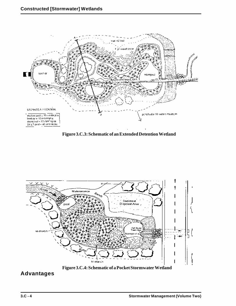
Stormwater Management (Volume Two)3.C - 4
Constructed [Stormwater] Wetlands
Figure 3.C.3: Schematic of an Extended Detention Wetland
Figure 3.C.4: Schematic of a Pocket Stormwater WetlandAdvantages

Stormwater Management (Volume Two) 3.C - 5
Constructed [Stormwater] Wetlands
Relatively low maintenance costs.
Has high pollutant removal efficiency.
Can enhance the aesthetics of a site and provide recreational benefits.
DisadvantagesDepending upon design, larger land requirements than for other BMPs.
Until vegetation is well established, pollutant removal efficiencies may belower than anticipated.
Relatively high construction costs in comparison to other BMPs.
ApplicabilityAs for other stormwater BMPs, stormwater wetlands should not be used tomanage the runoff during construction and site disturbance.
The use of stormwater wetlands is limited by a number of site constraints,including soils types, depth to groundwater, contributing drainage area, andavailable land area at site. Where land area is not a limiting factor, the use ofseveral wetland design types is possible; where land area is limited, the use ofthe pocket type wetland design may be possible.
Soils, depth to bedrock, and depth to water table must be investigated beforedesigning and siting stormwater wetlands. Medium-fine texture soils (such asloams and silt loams) are best to establish vegetation, retain surface water,permit groundwater discharge, and capture pollutants. At sites where infiltrationis too rapid to sustain permanent soil saturation, an impermeable liner may berequired. Where the potential for groundwater contamination is high, such asrunoff from sites with a high potential pollutant load, the use of liners should berequired.
At sites where bedrock is close to the surface, high excavation costs may makestormwater wetlands infeasible.
The recommended minimum design criteria for stormwater wetlands are listed inthe design section, Table 3.C.1.
EffectivenessTable 3.2 shows the range of removal efficiencies for stormwater wetlands.When the stormwater wetland is well planned, designed, constructed andmaintained, then the reduction of the pollutant loadings should be at the high endof the reported values.A review of the existing performance data indicates that the removal efficiencies

Stormwater Management (Volume Two)3.C - 6
Constructed [Stormwater] Wetlands
of stormwater wetlands are slightly higher than those of conventional pondsystems, e.g. as wet ponds or dry extended detention ponds. Of the fourdesigns described above, the pond/wetland system has shown the most reliablein terms of overall performance. It should be noted that the performance ofpocket wetlands has not been thoroughly monitored or reported. Removalefficiencies of pocket wetlands may be lower than other stormwater wetlanddesigns, when they lack forebays. Pocket wetlands maybe prone toresuspension problems, may lack the dense vegetative cover of otherstormwater wetland designs, and may lose volume to the groundwater.
Studies have also indicated that removal efficiencies of stormwater wetlandsdecline if they are covered by ice or receive snow melt. Performance alsodeclines during the non-growing season and during the fall when the vegetationdies back. Until vegetation is well established, pollutant removal efficiencies maybe lower than expected.
However, properly designed stormwater wetlands can be used to meet theStormwater Management Standards. An off-line stormwater wetland design, forrunoff quality treatment, in combination with an on-line runoff quantity controlBMP may be preferred because large surges of water can damage stormwaterwetlands. Furthermore, the shallow depths required to maintain the wetlands areat odds with the storage of large volumes, which are required to control runoffquantity.
Planning ConsiderationsSites must be carefully evaluated when planning stormwater wetlands. Soils,depth to bedrock, and depth to water table must be investigated before design-ing and siting stormwater wetlands.
A “pondscaping plan” should be developed for each stormwater wetland. Thisplan should include hydrological calculations (or water budget), a wetlanddesign and configuration, elevations and grades, a site/soil analysis, and esti-mated depth zones. The plan should also contain the location, quantity, andpropagation methods for the stormwater wetland plants. Site preparationrequirements, maintenance requirements and a maintenance schedule are alsonecessary components of the plan.
The water budget should demonstrate that there will be a continuous supply ofwater to sustain the stormwater wetland. The water budget should be devel-oped during site selection and checked after preliminary site design. Dryingperiods of longer than two months have been shown to adversely effect plantcommunity richness, so the water balance should confirm that drying will notexceed two months.Establishment and maintenance of the wetland vegetation is an importantconsideration when planning a stormwater wetland. Horner et al. (1994)

Stormwater Management (Volume Two) 3.C - 7
Constructed [Stormwater] Wetlands
compiled the following list of recommendations for creating wetlands:
In selecting plants, consider the prospects for success more than the specificpollutant capabilities. Plant uptake is an important removal mechanism fornutrients, but not for other pollutants. Information on vegetative pollutantremoval has been compiled, however. The most versatile genera, withspecies throughout the country, for pollutant removal appear to be Carex,Scirpus, Juncus, Lemna, and Typha.
Selection of native species should avoid those that invade vigorously.
Since diversification will occur naturally, use a minimum of species adapt-able to the various elevation zones within the stormwater wetland.
Give priority to perennial species that establish rapidly.
Select species adaptable to the broadest ranges of depth, frequency andduration of inundation (hydroperiod).
Match site conditions to the environmental requirements of plant selections.
Take into account hydroperiod and light conditions.
Give priority to species that have already been used successfully in con-structed wetlands and that are commercially available.
Avoid using only species that are foraged by the wildlife expected on site.
Establishment of woody species should follow herbaceous species.
Add vegetation that will achieve other objectives, in addition to pollutioncontrol.
The plant community will develop best when the soils are enriched with plantroots, rhizomes, and seed banks. Use of “wetlands mulch” enhances the diver-sity of the plant community and speeds establishment. Wetlands mulch is hydricsoil that contains vegetative plant material. This mulch can be obtained wherewetlands soils are removed during dredging, maintenance of highway ditches,swales, sedimentation ponds, retention/detention ponds, clogged infiltrationbasins, or from natural wetlands that are scheduled to be filled under permit.Wetland soils are also available commercially. The upper 5.9 inches of donorsoil should be obtained at the end of the growing season, and kept moist untilinstallation.Drawbacks to using wetlands mulch are its unpredictable content, limited donorsites, and the potential for the introduction of exotic, opportunistic species.Stormwater wetland vegetation development can also be enhanced through thenatural recruitment of species from nearby wetland sites. However, transplantingwetland vegetation is still the most reliable method of propagating stormwater

Stormwater Management (Volume Two)3.C - 8
Constructed [Stormwater] Wetlands
wetland vegetation, and it provides cover quickly. Plants are commerciallyavailable through wetland plant nurseries.
DesignSee the following reference for complete design references:
Design of stormwater wetland systems. 1992. Schueler. MWCOG Informa-tion Center.
Stormwater wetlands can be constructed on-line, to control the runoff volumesfrom design storms, in conjunction with off-line runoff quality control compo-nents. The off-line design requires two pond components and adds tostormwater system costs. Stormwater wetlands may also be designed as on-linesystems with a permanent pool area for treatment and a storage area for peakrunoff rate control.
Schueler (1992) cites the following basic stormwater wetland design sizingcriteria to follow to for optimum pollutant removal. These stormwater wetlanddesign criteria and additional considerations are summarized in Table 3.C.1.
Size for the prescribed water quality treatment volume.
Have a minimum surface area in relation to the contributing watershed area.The reliability of pollutant removal tends to increase as the stormwaterwetland to watershed ratio increases, although this relationship is not alwaysconsistent. The ratios of stormwater wetland to watershed listed in Table3.C.1 may be reduced when it can be demonstrated that the internalflowpath and microtopography in the stormwater wetland will increase thestorage area to volume ratio.
Design the stormwater wetlands with the recommended proportion of“depth zones.” Each of the four stormwater wetland designs has depthzone allocations which are given as a percentage of the stormwater wetlandsurface area. Target allocations for the four stormwater wetland designs arelisted in Table 3.C.2. The four basic depth zones are:
Deepwater zoneFrom 1.5 to six feet deep. This zone supports little emergent vegetation, but may support submerged or floating vegetation. This
zone can be further broken down into forebay, micropool anddeepwater channels.
Low marsh zoneRanges from 18 to six inches below the normal pool. This area issuitable for the growth of several emergent wetland plant species.
High marsh zoneRanges from six inches below the pool up to the normal pool. This

Stormwater Management (Volume Two) 3.C - 9
Constructed [Stormwater] Wetlands
zone will support a greater density and diversity of emergentwetland species than the low marsh zone. The high marsh zone shouldhave a higher surface area to volume ratio than the low marsh zone.
Semi-wet zoneAre those areas above the permanent pool that are inundated on anirregular basis that can be expected to support wetland plants.
Design each stormwater wetland with the recommended proportion oftreatment volumes, which have been represented as a percentage of thethree basic depth zones (pool, marsh, extended detention). The allocationsof treatment volume per zone are in both Table 3.C.1 and 3.C.2.
Meet, at least, a minimum standard for the internal flow path through thestormwater wetland. This is intended to create the longest possible flowpath through the stormwater wetland, and thereby increase the contact timeover the surface area of the marsh. The stormwater wetland should bedesigned to achieve a dry weather flow path of 2:1 (length: width) orgreater. A shorter flow path may be allowable for pocket wetlands.
Prepare a water budget to demonstrate that the water supply to thestormwater wetland is greater than the expected loss rate.
Provide extended detention for smaller storms (ED wetlands only). Schuelerlists the following design standards for ED wetlands:
-- The volume of the extended detention should be no morethan 50% of the total treatment volume.
-- The target ED detention time for this volume should be 12to 24 hours.
-- To ensure constant detention time for all storm events theuse of V-shaped or proportional weirs is encouraged.
-- Extended detention is defined here as the retention andgradual release of a fixed volume of stormwater runoff. ForED wetlands of less than 100 acres, the extended detentionvolume can be assumed to fill instantaneously.-- When using a reverse slope pipe, the actual diameter of the
orifice should be increased to the next greatest diameter onthe standard pipe schedule, since the pipe will be equippedwith a gate valve.
-- The ED orifice should be well protected from clogging.
-- The maximum extended detention water surface elevationshould not be greater than three feet above the normal pool.
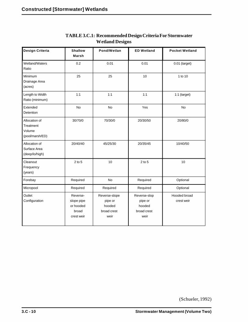
Stormwater Management (Volume Two)3.C - 10
Constructed [Stormwater] Wetlands
TABLE 3.C.1: Recommended Design Criteria For Stormwater Wetland Designs
Design Criteria ShallowMarsh
Pond/Wetlan ED Wetland Pocket Wetland
Wetland/WatersRatio
0.2 0.01 0.01 0.01 (target)
MinimumDrainage Area(acres)
25 25 10 1 to 10
Length to WidthRatio (minimum)
1:1 1:1 1:1 1:1 (target)
ExtendedDetention
No No Yes No
Allocation ofTreatmentVolume(pool/marsh/ED)
30/70/0 70/30/0 20/30/50 20/80/0
Allocation ofSurface Area(deep/lo/high)
20/40/40 45/25/30 20/35/45 10/40/50
CleanoutFrequency(years)
2 to 5 10 2 to 5 10
Forebay Required No Required Optional
Micropool Required Required Required Optional
OutletConfiguration
Reverse-slope pipeor hooded
broadcrest weir
Reverse-slopepipe orhooded
broad crestweir
Reverse-sloppipe orhooded
broad crestweir
Hooded broadcrest weir
(Schueler, 1992)

Stormwater Management (Volume Two) 3.C - 11
Constructed [Stormwater] Wetlands
TABLE 3.C.2: Recommended Allocation of Volumes for Stormwater Wetlands
(Schueler, 1992)
The following are approximate depth ranges cited by Schueler (1992) for thevarious stormwater wetland designs:
Shallow marsh 0.5 to 1.5 feetPond/marsh 2.0 to 2.8 feetED Wetland
Permanent pool 0.8 to 1.0 feetExtended detention zone 3.3 feet
Pocket wetland 0.5 to 1.3 feet
Each stormwater wetland should be designed with a separate cell near the inletto act as a sediment forebay. This forebay should have a capacity of at least10% of the total treatment volume, have a direct and convenient access forcleanout, and will normally have a depth of 4 to 6 feet.
A safety bench, with a minimum width of ten feet, should surround all deepwater cells; it should have a depth of zero to 18 inches below the normal waterelevation of the pool.
TargetAllocations
ShallowMarsh
Pond/Wetlan ED Wetland Pocket Wetland
% of SurfaceArea
Forebay 5 0 5 0
Micropool 5 5 5 0
Deepwater 5 40 0 5
Lo Marsh 40 25 40 50
Hi Marsh 40 25 40 40
Semi-wet 5 5 10 5
% of
TreatmentVolume
Forebay 10 0 10 0
Micropool 10 10 10 0
Deepwater 10 60 -- 20
Lo Marsh 45 20 20 55
Hi Marsh 25 10 10 25
Semi-wet 0 0 50 0

Stormwater Management (Volume Two)3.C - 12
Constructed [Stormwater] Wetlands
Above ground berms or high marsh wedges should be placed at approximately50 foot intervals, at right angles to the direction of the flow to increase the dryweather flow path within the stormwater wetland.
Before the outlet, a four to six foot deep micropool, (having a capacity of atleast ten percent of the total treatment volume), should be included in the designto prevent the outlet from clogging. A reverse slope pipe or a hooded, broadcrested weir is the recommended outlet control. The outlet from the micropoolshould be located at least one foot below the normal pool surface. To preventclogging, trash racks or hoods should be installed on the riser. To facilitateaccess for maintenance, the riser should be installed within the embankment.Anti-seep collars should be installed on the outlet barrel to prevent seepinglosses and pipe failures.
A bottom drain pipe with an inverted elbow to prevent sediment clogging shouldbe installed for complete draining of the stormwater wetland and for emergencypurposes or routine maintenance. Both the outlet pipe and the bottom drain pipeshould be fitted with adjustable valves at the outlet ends to regulate flows.
Embankments and spillways should be designed in conformance with the stateregulations and criteria for Dam Safety. All stormwater wetlands must have anemergency spillway capable of bypassing runoff from large storms withoutdamage to the impounding structure.
An access for maintenance, with a minimum width of 15 feet and a maximumslope of 15%, must be provided by public or private right-of-way. This accessshould extend to the forebay, safety bench and outflow structure and shouldnever cross the emergency spillway unless the spillway has been designed andconstructed for this purpose.
Vegetative buffers around the perimeter of the stormwater wetland are recom-mended for erosion control and additional sediment and nutrient removal.
ConstructionSchueler (1992) lists a seven step process for preparation of the wetland bedprior to planting:
Prepare final pondscaping and grading plans for the stormwater wetland. Atthis time order wetland plant stock from aquatic nurseries.
Once the stormwater wetland volume has been excavated, the wetlandshould be graded to create the major internal features (pool, aquatic bench,deep water channels, etc.).
Top soil and/or wetland mulch are added to the stormwater wetland exca-vation. Since deep subsoils often lack the nutrients and organic matter to
Stormwater Management (Volume Two) 3.C - 13
Constructed [Stormwater] Wetlands
support vigorous plant growth, the addition of mulch or topsoil is important.If it is available, wetland mulch is preferable to topsoil.
After the mulch or topsoil has been added, the stormwater wetland needs tobe graded to its final elevations. All wetland features above the normal poolshould be stabilized temporarily.
After grading to final elevations, the pond drain should be closed and thepool allowed to fill. A good design recommendation is to evaluate thewetland elevations during a standing period of approximately six months.During this time the stormwater wetland can experience stormflows andinundation, so that it can be determined where the pondscaping zones arelocated and whether or not the final grade and microtopography will persistover time.
Before planting, the stormwater wetland depths should be measured to thenearest inch to confirm planting depth. The pondscape plan may be modi-fied at this time to reflect altered depths or availability of plant stock.
Erosion controls should be strictly applied during the standing and plantingperiods. All areas above the normal pool elevation should be vegetativelystabilized during the standing period, usually with hydroseeding.
The stormwater wetland should be de-watered at least three days beforeplanting, as a dry wetland is easier to plant than a wet one.
MaintenanceStormwater wetlands require considerable routine maintenance, but do notrequire large, infrequent sediment removal, unlike conventional pond systemsthat require relatively minor routine maintenance and expensive sedimentremoval at infrequent intervals.
Careful observation of the system over time is required. In the first three yearsafter construction, twice a year inspections are needed during both the growingand non-growing season. Data gathered during these inspections should berecorded, mapped and assessed. The following observations should be madeduring the inspections:
Types and distribution of dominant wetland plants in the marsh;
The presence and distribution of planted wetland species; the presence anddistribution of volunteer wetland species; signs that volunteer species arereplacing the planted wetland species;
Percentage of unvegetated standing water (excluding the deep water cellswhich are not suitable for emergent plant growth);
The maximum elevation and the vegetative condition in this zone, if thedesign elevation of the normal pool is being maintained for wetlands with
Stormwater Management (Volume Two)3.C - 14
Constructed [Stormwater] Wetlands
extended zones.
Stability of the original depth zones and the microtopographic features;
Accumulation of sediment in the forebay and micropool; and
Survival rate of plants in the wetland buffer.
Regulating the sediment input to the wetland is the priority maintenance activity.The majority of sediments should be trapped and removed before they reachthe wetlands either in the forebay or in a pond component. Gradual sedimentaccumulation in the wetland results in reduced water depths and changes in thegrowing conditions for the emergent plants. Furthermore, sediment removalwithin the wetland can destroy the wetland plant community.
Shallow marsh and extended detention wetland designs include forebays to trapsediment before reaching the wetland. These forebays should be cleaned outevery year.
Pond/wetland system designs do not include forebays as the wet pond itself actsas an oversized forebay. Sediment cleanout of pond/wetland systems is neededevery 10 years.
Summary: Constructed [Stormwater] Wetland Guidelines
Site CriteriaStormwater wetlands require at least ten acres of contributing drainage areaand may require dry weather base flow in order to maintain appropriateshallow marsh water elevations.
The contributing drainage area to any individual pocket wetland may be oneto ten acres. Pocket type design wetlands should be excavated to ground-water.
Sites should be carefully evaluated before planning stormwater wetlands.Soils, depth to bedrock, and depth to water table must be investigatedbefore siting stormwater wetlands.The following minimum setback requirements should apply to stormwaterwetland installations:
-- Distance from a septic system leach field - 50 feet.-- Distance from a septic system tank - 25 feet.-- Distance from a property line - 10 feet.-- Distance from a private well - 50 feet.
Stormwater Management (Volume Two) 3.C - 15
Constructed [Stormwater] Wetlands
Design CriteriaBefore designing the stormwater wetland, a water budget should be devel-oped to ensure that there is an adequate and steady supply of water tomaintain the water elevations. A detailed plan should also be developed foreach stormwater wetland.
Stormwater wetlands should be sized to treat the prescribed water qualityvolumes and control the peak discharge rates from the 2 and 10 yearfrequency storm events.
The surface area and treatment volume of the stormwater wetland should beallocated to meet targets for the depth of components in the wetland (SeeTable 3.C.2).
The stormwater wetland should be designed to achieve a dry weather flowpath of 2:1 (length:width) or greater. A shorter flow path may be allowablefor pocket wetlands.
Each stormwater wetland should be designed with a separate cell near theinlet to act as a sediment forebay. This forebay should have a capacity of atleast 10% of the total treatment volume, have a convenient access forcleanout, and will normally have a depth of 4 to 6 feet.
A safety bench, with a minimum width of ten feet, should surround all deepwater cells; the bench should be at a depth of zero to 18 inches below thenormal water elevation of the pool.
Above ground berms or high marsh wedges should be placed at approxi-mately 50 foot intervals, and at right angles to the direction of the flow toincrease the dry weather flow path within the stormwater wetland.
At the outlet, include a 4 to 6 foot deep micropool, having a capacity of atleast ten percent of the total treatment volume, to prevent the outlet fromclogging. A reverse slope pipe or a hooded, broad crested weir is therecommended outlet control. The outlet from the micropool should belocated at least one foot below the normal pool surface.
To prevent clogging, trash racks or hoods should be installed on the riser.To facilitate access for maintenance, the riser should be installed near orwithin the embankment. Anti-seep collars should be installed on the outletbarrel to prevent seeping losses and pipe failures.
A bottom drain pipe with an inverted elbow should be installed for completedraining of the stormwater wetland for emergency purposes or routine

Stormwater Management (Volume Two)3.C - 16
Constructed [Stormwater] Wetlands
maintenance. Both the outlet pipe and the bottom drain pipe should befitted with adjustable valves at the outlet ends to regulate flows.
Embankments and spillways should be designed in conformance with thecriteria in the state Dam Safety regulations. All stormwater wetlands musthave an emergency spillway capable of bypassing runoff from large stormswithout damage to the impounding structure.
An access for maintenance, with a minimum width of 15 feet and a maxi-mum slope of 15%, must be provided by public or private right-of-way.Access must extend to forebays, safety bench and outflow structure.
Vegetative buffers around the perimeter of the stormwater wetland arerecommended for erosion control and additional sediment and nutrientremoval.
Construction CriteriaOnce the stormwater wetland volume has been excavated, the wetlandshould be graded to create the major internal features (pool, aquatic bench,deep water channels, etc.). Top soil and/or wetland mulch are added to thestormwater wetland excavation, and the stormwater wetland is graded to itsfinal elevations. All wetland features above the normal pool should bestabilized temporarily.
After grading to final elevations, the pond drain should be closed and thepool allowed to fill. Usually nothing should be done to the stormwaterwetland for six to nine months or until the next planting season. During thistime the stormwater wetland can experience stormflows and inundation, sothat it can be determined where the pondscaping zones are located andwhether or not the final grade and microtopography will persist over time.
Before planting, the stormwater wetland depths should be measured to thenearest inch to confirm planting depth. The pondscape plan may be modi-fied at this time to reflect altered depths or availability of plant stock.
The stormwater wetland should be de-watered at least three days beforeplanting, as a dry wetland is easier to plant than a wet one.
Maintenance CriteriaMaintenance is required for the proper operation of stormwater wetlands.Plans for stormwater wetlands should identify owners, parties responsiblefor maintenance, and an inspection and maintenance schedule.
Stormwater wetlands require considerable routine maintenance, but do notrequire large, infrequent sediment removal.
Regulating the sediment input to the wetland is the priority maintenanceactivity. The majority of sediments should be trapped and removed beforethey reach the wetland. Sediment accumulation in the wetland gradually

Stormwater Management (Volume Two) 3.C - 17
Constructed [Stormwater] Wetlands
results in reduced water depths and changes in the growing conditions forthe emergent plants. In addition, sediment removal within the wetland candestroy the wetland plant community.
Shallow marsh and ED wetland designs should include forebays to trapsediment before reaching the wetland. These forebays should be cleanedout every year.
Pond/wetland system designs may not include forebays as the wet ponditself acts as an oversized forebay. Sediment cleanout of pond/wetlandsystems is needed every 10 years.
Careful observation of the system development over time is required. In thefirst three years after construction, twice a year inspections are requiredduring both the growing and non-growing seasons. Data gathered duringthese inspections should be recorded, mapped and assessed.

Stormwater Management (Volume Two) 3.D - 1
Water Quality Swales
Water Quality Swales
DefinitionThe difference between water quality swales and drainage channels is in thedesign and planned use of the open channel conveyance.
Water quality swales are designed primarily for the prescribed stormwaterwater quality volume and have incorporated specific features to enhancetheir stormwater pollutant removal effectiveness. Pollutant removal ratesare significantly higher for water quality swales than for drainage channels.Water quality swales include dry swales, wet swales, and grassed swales or“biofilters”.
Drainage channels, on the other hand, are designed with sufficient capacityto convey runoff safely, without erosion, during large (10-year frequency)storm events. Other than basic channel size and geometry, there are nospecific design modifications to enhance pollutant removal capabilities.Typically, pollutant removal efficiency is very low for drainage channels.See section 3.K for a discussion on drainage channel design.
Figure 3.D.1 provides a schematic of a dry swale, Figure 3.D.2 depicts atypical wet swale, and Figure 3.D.3 illustrates a grassed “biofilter” swale.
Figure 3.D.1: Schematic of a Dry Swale
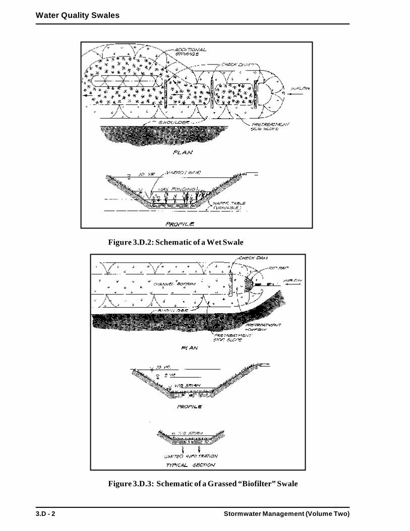
Stormwater Management (Volume Two)3.D - 2
Water Quality Swales
Figure 3.D.2: Schematic of a Wet Swale
Figure 3.D.3: Schematic of a Grassed “Biofilter” Swale
ROAD
ROAD
ROAD
Stormwater Management (Volume Two) 3.D - 3
Water Quality Swales
PurposeTo provide control for certain peak runoff rates by retarding andimpounding stormwater and conveying it downstream at velocities lowenough to protect against channel and streambank erosion.
To provide runoff volume control, (especially for dry swales), by meansof gradual infiltration of stormwater, as it passes through the waterquality swale.
To provide moderate to high pollutant removal through sedimentation,filtration, nutrient uptake, and infiltration.
AdvantagesControls peak discharges by reducing runoff velocity and promotinginfiltration (especially for dry swales).
Provides pretreatment by trapping, filtering and infiltrating particulateand associated pollutants.
Generally less expensive than curb and gutter systems.
Roadside swales provide water quality and quantity control benefits,while reducing driving hazards by keeping stormwater flows away fromstreet surfaces.
Accent natural landscape.
DisadvantagesHigher degree of maintenance required than for curb and gutter sys-tems.
Roadside swales are subject to damage from off street parking andsnow removal.
ApplicabilityWater quality swales are widely applicable, especially the three types ofmodified designs. Swales are most applicable to residential and institutionalareas of low to moderate density. The percentage of impervious cover inthe contributing areas should be relatively small, however. Water qualityswales can also be used in parking lots to break up areas of imperviouscover.
It should be noted that wet swales may not be desirable for some residen-tial applications, such as frontage lots, because standing and stagnant watermay be present at times.
Along the edge of smaller roadways, water quality swales can be used inplace of curb and gutter systems. Water quality swales may be used in
Stormwater Management (Volume Two)3.D - 4
Water Quality Swales
connection with drainage channels to overcome space and other con-straints. Water quality swales may not be applicable to sites with manydriveway culverts or extensive sidewalk systems. When using water qualityswales in combination with roadways and sidewalks, it is most appropriateto place the swale between the two impervious areas.
The topography and soils on the site will determine the applicability ofcertain design modifications for water quality swales. The topographyshould allow for the design of a swale with sufficient slope and cross-sectional area to maintain nonerosive flow velocities. Porous soils lendthemselves to the use of dry swales and grassed “biofilter” swales, whilesoils with poor drainage are more suited to wet swales. Water qualityswales are designed to retain and treat the entire water quality volume, butmay also be able to convey additional runoff volume to otherdowngradient BMPs.
EffectivenessTable 3.2 shows the range of pollutant removal efficiencies for waterquality swales. When the swale is well planned, designed, constructed andmaintained, then the reduction of pollutant loadings should be at the highend of the reported values. Based on the probable range of results, carefulconsideration must be given to design and proper siting to meet the Storm-water Management Standards. Pretreatment devices, such as forebaysbehind checkdams are necessary.
Water quality swales assist in controlling runoff volumes and peak dis-charge rates in several ways, depending on the type of swale. Dry swalesrely primarily on infiltration through existing or imported soils. Wet swalesachieve pollutant removal both from sediment accumulation and mechani-cal removal, and through trapping and uptake by wetland vegetation.Grassed swales also utilize biological uptake, in addition to sedimenttrapping.
Planning ConsiderationsWhen designing a water quality swale, the primary considerations are soils,capacity, erosion resistance and vegetation. Site conditions and designspecifications limit the use of water quality swales. Generally, at least oneof the three basic swale types will be suited to the development site.
Swale capacity should be based on the maximum expected reduction invelocity which occurs during the annual peak growth period. Usually themaximum expected drop in velocity occurs when vegetation is at its maxi-mum growth for the year. The minimum level should be used when check-ing velocity through the swale. This usually occurs during the early grow-ing season and dormant periods.
Other important factors to be considered when planning for water qualityswales are land availability, maintenance requirements and soil characteris-
Stormwater Management (Volume Two) 3.D - 5
Water Quality Swales
tics. The topography of the site should allow for the design of a swale withsufficient slope and cross-sectional area to maintain a nonerosive flow rate,and to retain/detain the prescribed water quality runoff volume. The longi-tudinal slope of the swale should be as close to zero as possible and notgreater than 5%.
The grass or vegetation types used in swales should be suited to soil andwater conditions. Wetland hydrophytes or obligate species are generallymore water tolerant than facultative species and are good selections forwet swales, while grassed swales should be planted with species thatproduce fine and dense cover and are adapted to varying moisture condi-tions.
DesignSee the following for complete design references:Site Planning for Urban Stream Protection. 1995. Schueler. Center forWatershed Protection.
Watershed Protection Techniques, Volume 2, Number 2, 1996. Center forWatershed Protection.
Biofiltration swale performance, recommendations, and design consider-ations. 1992. Metro Seattle: Water Pollution Control Department, Seattle,WA.
Dry SwalesDry swales should be sized to infiltrate the entire prescribed water qualityrunoff volume, allowing for full filtering or infiltration through the bottomof the swale. It is often necessary to modify the parent soils to improvetheir infiltration rate.
Dry swales should have a soil bed that is 30 inches deep and composed ofapproximately 50% sand and 50% loam.
Pretreatment is required to protect the filtering and infiltration capacity ofthe swale bed. Pretreatment is generally a sediment forebay behind acheckdam with a pipe inlet. For lateral inflows, gentle slopes or a peagravel diaphragm may be used.
Where soils do not permit full infiltration, a longitudinal perforatedunderpipe should be placed on the bottom of the swale bed.
Dry swales are parabolic or trapezoidal in cross-section, with side slopesno greater than 3:1 (horizontal:vertical) and bottom widths ranging from 2to 8 feet.
Channels should be sized to convey the 10-year storm and channel slopes
Stormwater Management (Volume Two)3.D - 6
Water Quality Swales
and backs should be designed to prevent erosions during the 2-year event.Seasonal high water table should not be within 2-4 feet of planned dryswale bottom.
Outlet protection must be used at any discharge point from a water qualityswale to prevent scour at the outlet.
Wet SwalesWet swales should be sized to retain the entire prescribed water qualityrunoff volume.
Wet swales should only be used where the water table is at or near the soilsurface or where soil types are poorly drained. When the channel is exca-vated, the swale bed soils should be saturated most of the time.
Pretreatment is required to protect the filtering and infiltration capacity ofthe swale bed. Pretreatment is generally a sediment forebay behind acheckdam with a pipe inlet. For lateral inflows, gentle slopes or a peagravel diaphragm may be used.
Check dams are used in wet swales to achieve multiple cells. V-notchedweirs in the check dams can be utilized to direct low flow volumes.
Emergent vegetation should be planted, or wetland soils may be spread, onthe swale bottom for seed stock.
Wet swales are parabolic or trapezoidal in cross-section, with side slopesno greater than 3:1 (horizontal:vertical) and bottom widths ranging from 2to 8 feet.
Channels should be sized to convey the 10 year storm and channel slopesshould be designed to prevent erosion during the 2 year event.
Outlet protection must be used at any discharge point from water qualityswales to prevent scour at the outlet.
Grassed “Biofilter” SwalesGrassed swales should be sized to retain the entire prescribed water qualityvolume.
Longitudinal slopes should be as close to zero as possible and not exceed4%.
The preferred grassed swale geometry avoids sharp corners and has atrapezoidal or parabolic cross-section with side slopes no greater than 3:1.
Swale bottoms should not exceed 8 feet in width.

Stormwater Management (Volume Two) 3.D - 7
Water Quality Swales
Channels should be sized to convey the 10 year storm and channel slopesshould be designed to prevent erosion during the 2 year event.
Soils should generally be sandy loam, with an organic matter of 10-20%and no more than 20% clay. Parent soils may be augmented to achievenecessary conditions.
Grass species that produce fine, uniform, and dense cover that can with-stand prevailing moisture conditions should be selected. Poorly drainedsoils may require wetland adapted species.
Outlet protection must be used at discharge points from water qualityswales to prevent scour at the outlet.
ConstructionTemporary erosion and sediment controls should be utilized during con-struction. The vegetation mix should be selected to suit the characteristicsof the site. Seeding will require mulching with appropriate materials, suchas, mulch matting, straw, and wood chips. Mulch should be anchoredimmediately after seeding. New seedlings should be watered well untilthey are established. Refer to “Massachusetts Erosion and Sediment Con-trol Guidelines for Urban and Suburban Areas: A Guide for Planners,Designers, and Municipal Officials” on sediment/erosion control for infor-mation regarding seeding and mulching.
MaintenanceA maintenance and inspection schedule should be incorporated into thedesign to ensure the effectiveness of water quality swales. Swales should beinspected on a semi-annual basis; additional inspections should be sched-uled during the first few months to make sure that the vegetation in theswales becomes adequately established. The water quality swales should beinspected for slope integrity, soil moisture, vegetative health, soil stability,soil compaction, soil erosion, ponding and sedimentation.
Regular maintenance tasks include mowing, fertilizing, liming, watering,pruning, and weed and pest control. Swales should be mowed at least onceper year. The grass must not be cut shorter than four inches because theeffectiveness of the vegetation in reducing flow velocity and pollutantremoval may be reduced.
Sediment and debris should be removed manually, at least once per year,and periodic reseeding may be required to maintain the dense growth ofvegetation. Care should be taken to protect water quality swales fromsnow removal and disposal practices and off street parking. Since swalesmay be located on private residential property, it is important for develop-ers to clearly outline the maintenance requirements to property purchasers.
Stormwater Management (Volume Two)3.D - 8
Water Quality Swales
Summary: Guidelines for Water Quality Swales
Site CriteriaThe topography of the site should allow for a longitudinal slope of nogreater than 5%.
Soils are a consideration for the type of water quality swale planned. Insome cases, parent soil may need to be augmented to utilize dry swalesand grassed “biofilter” swales.
Widely applicable to residential and low density commercial and indus-trial sites. Road applications excellent.
Design CriteriaPretreatment is typically a forebay behind a checkdam. Gentle slopes orpea gravel diaphragms for lateral inflows.
Water quality swales should be designed to capture and treat the entireprescribed stormwater runoff water quality volume.
The longitudinal slope in the water quality swale should not exceed5%.
Side slopes of 3:1 or flatter are recommended for maintenance and toprevent side slope erosion. Runoff velocities should not cause erosionfor the 2 year stormwater runoff event. The swale should be sized toconvey the 10 year storm volume.
Dry swales require 30 inch deep bed of well drained soils, consisting ofabout 50% sand and 50% loam. Onsite soils may be enhanced, andwhere well drained soils do not exist, a perforated underdrain should beutilized.
Wet swales require saturated soil conditions to support wetland vegeta-tion. Check dams must be utilized to establish multiple cells.
Grassed swales should be sandy loam or a similar soil type with nomore than 20% clay. Soil augmentation may be necessary. Dense grasscover must be achieved.
Outlet protection must be used at any discharge point from a waterquality swales to prevent scour.
Construction CriteriaTemporary erosion and sediment controls should be utilized duringconstruction.
Mulch anchoring should be done immediately after seeding.

Stormwater Management (Volume Two) 3.D - 9
Water Quality Swales
Maintenance CriteriaMaintenance is required for the proper operation of water qualityswales. Plans for water quality swales should identify owners, partiesresponsible for maintenance, and an inspection and maintenance sched-ule.
Water quality swales should be inspected at least semi-annually, andmaintenance and repairs made as necessary. Additional inspectionsshould be scheduled during the first few months to make sure thevegetation becomes adequately established. Repairs and reseedingshould be done as required.
Swales should be mowed at least once per year. Grass clippings shouldbe removed. The grass must not be cut too often or shorter than fourinches, in order to maintain the effectiveness of the swale.
Sediment and debris should be removed manually, at least once peryear, before the vegetation is adversely impacted.
Care should be taken to protect water quality swales from snow re-moval and disposal practices and off street parking.
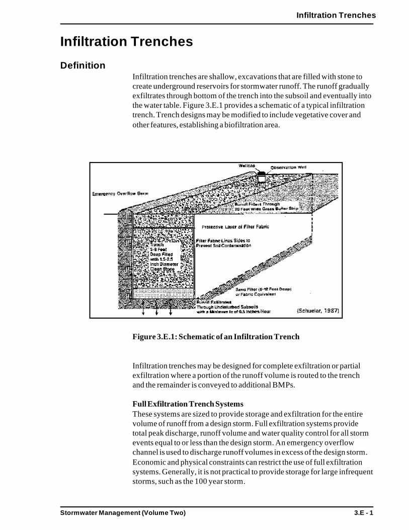
Stormwater Management (Volume Two) 3.E - 1
Infiltration Trenches
Infiltration Trenches
DefinitionInfiltration trenches are shallow, excavations that are filled with stone tocreate underground reservoirs for stormwater runoff. The runoff graduallyexfiltrates through bottom of the trench into the subsoil and eventually intothe water table. Figure 3.E.1 provides a schematic of a typical infiltrationtrench. Trench designs may be modified to include vegetative cover andother features, establishing a biofiltration area.
Figure 3.E.1: Schematic of an Infiltration Trench
Infiltration trenches may be designed for complete exfiltration or partialexfiltration where a portion of the runoff volume is routed to the trenchand the remainder is conveyed to additional BMPs.
Full Exfiltration Trench SystemsThese systems are sized to provide storage and exfiltration for the entirevolume of runoff from a design storm. Full exfiltration systems providetotal peak discharge, runoff volume and water quality control for all stormevents equal to or less than the design storm. An emergency overflowchannel is used to discharge runoff volumes in excess of the design storm.Economic and physical constraints can restrict the use of full exfiltrationsystems. Generally, it is not practical to provide storage for large infrequentstorms, such as the 100 year storm.

3.E - 2 Stormwater Management (Volume Two)
Infiltration Trenches
Partial or Water Quality Exfiltration Trench SystemsThis design exfiltrates a portion of the runoff, while the remainder isconveyed to additional BMPs. Two methods of partial infiltration arerecommended. The first relies on off-line treatment where a portion of therunoff, or the “first-flush,” is routed from the main channel into the trenchby means of a weir structure or other diversion. The second method is on-line, and utilizes a perforated pipe at the top of the trench. When the trenchhas filled to capacity, the excess runoff volumes are discharged through theperforated pipe to other BMP structures.
PurposeTo reduce runoff volume and peak discharge through infiltration(groundwater recharge).
To remove soluble and particulate pollutants from runoff.
AdvantagesPromotes groundwater recharge.
Reduces downstream flooding and protects streambank integrity.
Preserves the natural water balance of the site.
Provides a high degree of runoff pollution control when properlydesigned and maintained.
Reduces the size and cost of downstream stormwater control facilitiesand/or storm drain systems by infiltrating stormwater in upland areas.
Utilized where space is limited.
DisadvantagesHigh failure rates due to improper siting, design, construction andmaintenance.
Generally, use is restricted to small drainage areas.
Depending on soil conditions and aquifer susceptibility, a slight risk ofgroundwater contamination exists.
Requires frequent maintenance.
Susceptible to clogging by sediment.
ApplicabilityInfiltration trenches are feasible at sites with gentle slopes, permeable soils,and where bedrock and seasonal high groundwater levels are at least four

Stormwater Management (Volume Two) 3.E - 3
Infiltration Trenches
feet below surface. Contributing drainage areas should be relatively small,and should not exceed 5 acres. Infiltration trenches are suitable for parkinglots, rooftop areas and small residential developments.
Infiltration trenches should always be constructed with pretreatment. Theuse of infiltration technologies should be avoided in high potential pollutantloading areas. In groundwater drinking supply recharge areas (Zone II andInterim Wellhead Protection Areas (IWPA)), infiltration technologies maybe used for uncontaminated rooftop runoff only.
With these considerations in mind, the most efficient way to encourageinfiltration and reduce pollutant loadings in a cost efficient manner is toseparate contaminated runoff from uncontaminated runoff. Uncontami-nated stormwater runoff may be infiltrated directly, while contaminatedrunoff (such as from roads, parking areas and driveways) must be collectedand treated using an appropriate BMP or BMP combination, and thensubsequently routed (after treatment) back into infiltration facilities. In thismanner, the infiltration facilities perform double-duty: 1) they infiltrateuncontaminated stormwater during and immediately following the stormevent, and 2) they provide infiltration for pretreated stormwater frompolluted areas following an appropriate detention/treatment time for theselected design.
Infiltration trenches should always be constructed with pretreatment. Theuse of infiltration technologies should be avoided in high potential pollutantloading areas. In groundwater drinking supply recharge areas (Zone II andInterim Wellhead Protection Areas (IWPA)), infiltration technologies maybe used for uncontaminated rooftop runoff only.
Infiltration trenches are adaptable to many sites because of their thinprofile. The recommended site criteria are listed in Table 3.E.1.
Infiltration trenches can be used in upland areas of larger sites to reduce theoverall amount of runoff and improve water quality in the lower areas ofthese sites, thereby reducing the size requirements and costs for down-stream BMPs.
With the addition of water tolerant plant species and other design modifica-tions, pollutant removal performance, aesthetic value, and wildlife benefitsmay be enhanced. This type of biofiltration is a cross between an infiltrationtrench and an infiltration basin.
EffectivenessInfiltration trenches are not intended to remove coarse particulate pollut-ants; these must be removed by a pretreatment device before entering thetrench. The pollutant removal efficiency is dependent upon how muchrunoff is exfiltrated by the trench. Thus, full exfiltration systems providegreater pollutant removal than partial exfiltration systems, which, in turn,

3.E - 4 Stormwater Management (Volume Two)
Infiltration Trenches
are more efficient than water quality exfiltration systems.Infiltration trenches can be used to meet the stormwater quantity standardsunder optimum site conditions. Infiltration trenches have the potential tonearly reproduce the natural, pre-development hydrological regime at asite. Full exfiltration systems, that have been carefully designed, may becapable of controlling the 2 and 10 year peak discharge rate.
With pretreatment components, infiltration trenches can be used to meetthe Stormwater Management Standards. Full exfiltration systems should beable to meet the quantity standards, but careful design and site investiga-tion are warranted.
Planning ConsiderationsSites must be evaluated carefully before planning infiltration trenches.Soils, depth to bedrock, and depth to water table must be investigated.Soils should have a minimum percolation rate of 0.5 inches per hour.
Slopes of the contributing drainage area should not be steep, an generallyshould not exceed 5%.
Infiltration trenches have an extremely high failure rate which is usually dueto clogging. Pretreatment (water quality inlets or deep sump catch basins,swales with check dams, or sediment forebays/traps) should be a funda-mental component of any BMP system relying on infiltration. Infiltrationtrenches are not intended to remove coarse particulate pollutants, andgenerally are difficult to rehabilitate once clogged. It is important to notethat this general practice applies also when infiltrating rooftop runoff, eventhough in most cases it is presumed to be uncontaminated. It is a practicaldecision to implement some form of pretreatment to remove sediments,leaf litter, and debris. This pretreatment will help to ensure the properfunctioning of the infiltrating facility and allow for longer periods betweenmaintenance. Some examples of pretreatment controls include waterquality inlets, vegetated drainage systems, and sediment traps. Thesecontrols, when designed properly, may remove some 25-30% of sedimentloads. These pretreatment controls alone will not suffice to meet the 80%standard.
The appropriateness of infiltration methods for stormwater managementshould be considered in recharge areas. Depending on the potential risk ofgroundwater contamination from polluted runoff, it may be necessary torestrict rooftop runoff for groundwater drinking water supply rechargeareas (Zone II and IWPA). Infiltration trenches need to be setback outsideZone I and Zone A for public drinking water supplies (400 feet from thesource and 100 feet from the tributaries.)

Stormwater Management (Volume Two) 3.E - 5
Infiltration Trenches
Designing trenches for accessibility and ease of maintenance is important.Design
See the following for complete design references:
Stormwater Infiltration. 1994. Ferguson. CRC Press. 2000 CorporateBlvd. NW, Boca Raton, FL. 33431.
Standards and Specifications for Infiltration Practices. 1984. MarylandDept. of Environment. Baltimore, MD.
The volume and surface area of an infiltration trench relate to the quantityof runoff entering the trench from the contributing area, the void space, andthe infiltration rate. Since the infiltration trench is filled with stone, only thespace between the stone is available for runoff storage. Infiltration trenchesare to be filled with 1.5 - 3.0 inch diameter, clean washed stone. The finalsoil infiltration rate below the trench is determined by a geotechnical study.A minimum of two borings should be taken for each infiltration trench.Trenches over 100 feet in length should include at least one additionalsample for each 50 foot increment. Borings should be taken at the actuallocation of the proposed infiltration trench to identify localized soil condi-tions. The design of the infiltration trench should be based on the slowestrate obtained from the infiltration tests performed at the site. The minimumacceptable rate is 0.5 inches per hour.
The maximum depth of the trench must be at least two feet above theseasonal high water table or bedrock, and below the frost line.
Pretreatment is required to remove sediment and oil and grease which mayprematurely clog the trench. A water quality inlet (oil and grease separatoror sump pit) or a vegetated swale may be utilized for pretreatment. Inaddition, a vegetated buffer (20 foot minimum) around surface trenches isrecommended. Permeable filter fabric should be placed 6 to 12 inchesbelow the surface of the trench, along the sides, and at the bottom of thetrench. Using filter fabric, especially at the surface will help prevent clog-ging; if failure does occur, it can be alleviated without reconstructing theinfiltration trench. Twelve inches of sand may also be used at the bottom ofthe trench.
An observation well should be installed at the center of the trench tomonitor runoff clearance from the system. This well should consist of awell anchored, vertical perforated PVC pipe with a lockable abovegroundcap.
As described in the next section on construction considerations, measuresmust be taken at the outset, before any soil disturbance or construction on
3.E - 6 Stormwater Management (Volume Two)
Infiltration Trenches
the site begins to ensure that the infiltration trench will operate as designed.
ConstructionThe minimum construction criteria for infiltration trenches are presented inTable 3.E.1. Care should be taken during construction to minimize the riskof premature failure of the infiltration trench.
First, heavy equipment should not operate on the surface location wherethe infiltration trenches are planned. Soil compaction will adversely effectthe performance of the trench, and infiltration trench sites should be ropedoff and flagged.
Infiltration trenches should not be constructed until after the site has beenstabilized. Trenches should never be used as temporary sediment traps forconstruction activities.
Diversion berms or staked and lined haybales should be utilized around theperimeter of the infiltration trench during its construction. For the excava-tion and construction of the trench, manual removal or light earth-movingequipment is recommended. All excavated material from the trench siteshould be located downgradient to prevent redeposition of this material inthe trench during runoff events.
Once excavated, the sides and bottom of the trench should be lined withpermeable, geotextile fabric. Twelve inches of sand (clean, fine aggregate)may be substituted or used in addition on the bottom. One to three inchclean, washed stone should be placed in the lined trench and lightly com-pacted with plate compactors, to within approximately one foot to thesurface. Fabric filter should then be placed over the top, with at least a 12inch overlap on the sides. An underground trench may then be filled withtopsoil and planted. A surface trench may be filled with more aggregatestone.
MaintenanceBecause infiltration trenches are prone to failure due to the clogging of theporous soils, it is imperative that aggressive maintenance plans and sched-ules be developed and implemented for these BMPs. The use of pretreat-ment BMPs will significantly minimize maintenance requirements of thetrench itself. Removing accumulated sediment from a sump pit or a veg-etated swale is considerably less difficult and less costly than rehabilitatinga trench. Eventually, the infiltration trench should be rehabilitated, but thistime span is relative to the effective performance of the trench. Withappropriate design and aggressive preventive maintenance, this rehabilita-tion may not be necessary for a decade or more.
Preventive maintenance should be performed at least twice a year, andideally sediment should be removed from pretreatment BMPs after every

Stormwater Management (Volume Two) 3.E - 7
Infiltration Trenches
major storm event.
The infiltration trench should be inspected after the first several rainfallevents, after all major storms (2 year), and on regular bi-annual scheduleddates. Ponded water inside the trench (as visible from the observation well)after 24 hours or several days often indicates that the bottom of the trenchis clogged. Water ponded at the surface of the trench may indicate onlysurface clogging.
Clogging in trenches occurs most frequently on the surface. Grass clip-pings, leaves, and accumulated sediment should be removed routinely fromthe surface of the trench.
Pretreatment BMPs should be inspected and cleaned during the regular bi-annual inspections. Vegetated swales should be cleared of accumulatedsediment and mowed, then grass clippings, leaves, and trash should beremoved. Tree seedlings should be removed before becoming establishedfirmly. Water quality inlets should be cleared of accumulated sediment,leaves and debris at each regular inspection, and more frequently whereappropriate. Inlet and outlet pipes should be checked for clogging.
When ponding occurs at the surface or in the trench, corrective mainte-nance is required immediately. If the clogging appears only to be at thesurface, it may be necessary to remove and replace the topsoil or first layerof stone aggregate and the filter fabric. Ponding water in the trench indi-cates infiltration failure from the bottom. In this case, all of the stoneaggregate and filter fabric or media must be removed. Accumulated sedi-ment should be stripped from the trench bottom. At this point the bottommay be scarified or tilled to help induce infiltration. New fabric and cleanstone aggregate should be refilled.
Summary: Infiltration Trench Guidelines
Site CriteriaThe contributing drainage area to any individual infiltration trenchshould be restricted to small areas, 5 acres or less.
The minimum depth to the seasonal high water table, bedrock, and/orimpermeable layer should be two feet from the bottom of the trench.
The minimum acceptable soil infiltration rate should be 0.5 inches perhour. Maximum soil infiltration rates should generally not exceed 2.4inches per hour to ensure adequate pollutant removal.
A minimum of two soil borings should be taken for each infiltrationtrench. Infiltration trenches over 100 feet in length should include atleast one additional boring location for each 50 foot increment. Boringsshould be taken at the actual location of the proposed infiltration trench
3.E - 8 Stormwater Management (Volume Two)
Infiltration Trenches
so that any localized soil conditions are detected.Infiltration trenches should not be used at sites where soils have 30%or greater clay content, or 40% or greater silt clay content. Infiltrationtrenches will not function adequately in areas with hydologic soils ingroup D and infiltration will be limited for hydrologic soils in group C.
Infiltration trenches should not be placed over fill materials.
The following setback requirements apply to infiltration trench installa-tions:
-- Distance from any slope greater than 5% to any surface-exposed trench: minimum of 100 feet.
-- Distance from any slope greater than 20% to any underground trench: minimum of 100 feet.
-- Distance from any septic system component: minimum of100 feet.
-- Distance from any private well: minimum of 100 feet,additional setback distance may be required depending onhydrogeological conditions.
-- Distance from any public groundwater drinking supplies:Zone I radius, additional setback distance may be requireddepending on hydrogeological conditions.
-- Distance from any surface water supply and its tributaries:Zone A (400 feet from surface supply and 100 feet from itstributary).
Distance from any surface water of the Commonwealth (other thansurface drinking water supplies and their tributaries): minimum of 150feet downslope and 100 feet upslope.
Distance from any building foundations: minimum of 20 feet.
Design CriteriaThe design of the infiltration trench should be based on the slowestrates obtained from the soil infiltration tests performed at the site.
The depth of the infiltration trench should be adjusted so that themaximum drain time is 72 hours for the total runoff volume, with aminimum retention time of 48 hours.
Pretreatment is required to remove sediment and oil and grease whichmay clog the trench. Water quality inlets, deep sump catch basins, orvegetated swales are recommended. A vegetated filter strip around
Stormwater Management (Volume Two) 3.E - 9
Infiltration Trenches
surface trenches (minimum 20 feet) should also be utilized.An observation well should be installed at the trench’s center line tomonitor the runoff clearance through the system. This well shouldconsist of a well anchored, vertical perforated PVC pipe with a lock-able aboveground cap.
The sides and bottom of the infiltration trench should be lined withgeotextile fabric (filter fabric). The material selected must be compat-ible with the surrounding soil textures and application purposes. Thecut width of the filter fabric must have sufficient material for a mini-mum 12 inch overlap. When overlaps are required between rolls, theupstream roll must lap a minimum of two feet over the downstream rollto provide a shingled effect. The bottom of the infiltration trench can becovered with a six to twelve inch layer of clean sand (VDOT FineAggregate-Grading A or B) in place of filter fabric.
The trench should be filled with clean, washed aggregate stone with adiameter of 1.5 to 3 inches. The stone should be placed in the trench inlifts and lightly compacted with plate compactors to form the basecourse. The surface of the trench should also be lined with permeablefilter fabric and then capped with topsoil or more aggregate stone.
Construction CriteriaInfiltration trenches should never serve as temporary sediment traps forconstruction.
Before the development site is graded, the area of the infiltration trenchshould be roped off and flagged to prevent heavy equipment fromcompacting the underlying soils.
Infiltration trenches should not be constructed until the entire contrib-uting drainage area has been stabilized. Diversion berms should beplace around the perimeter of the infiltration trench during all phases ofconstruction. Sediment and erosion controls should be used to keeprunoff and sediment away from the trench area.
During and after excavation, all excavated materials should be placeddownstream, away from the infiltration trench, to prevent redepositionof these materials during runoff events. These materials should beproperly handled and disposed of during and after construction.
Light earth-moving equipment should be used to excavate the infiltra-tion trench. Use of heavy equipment causes compaction of the soilsbeneath the trench floor, resulting in reduced infiltration capacity.
Maintenance CriteriaMaintenance is required for the proper operation of infiltration trenches- plans for infiltration trenches should identify owners, parties respon-

3.E - 10 Stormwater Management (Volume Two)
Infiltration Trenches
sible for maintenance, and an inspection and maintenance schedule.Infiltration trenches are prone to failure due to clogging. The use ofpretreatment BMPs will minimize failure and maintenance require-ments. Aggressive maintenance plans and schedules should also help topreserve the effectiveness of the system.
After construction, infiltration trenches should be inspected after everymajor storm for the first few months to ensure proper stabilization andfunction. Thereafter, the trench should be inspected at least twice peryear. Water levels in the observation well should be recorded overseveral days to check trench drainage.
Preventive maintenance should be performed at least twice a year, andideally sediment should be removed from pretreatment BMPs afterevery major storm event.
Ponded water inside the trench (as visible from the observation well)after 24 hours or several days most likely indicates that the bottom ofthe trench is clogged.
Water ponded at the surface of the trench may indicate only surfaceclogging.
Clogging in trenches occurs most frequently on the surface. Grassclippings, leaves, and accumulated sediment should be removed asfrequently as possible from the surface of the trench.
Pretreatment BMPs should be inspected and cleaned at a minimumduring the regular bi-annual checks, and more frequently if possible.Vegetated swales should be cleared of accumulated sediment, mowed,and then grass clippings, leaves, and trash should be removed. Treeseedlings that become established should be removed. Water qualityinlets should be cleared of accumulated sediment, leaves, and debris ateach regular inspection, and more frequently if possible. Inlet and outletpipes should be checked for clogging.
When ponding occurs at the surface or in the trench, corrective mainte-nance is required immediately.
For surface clogging, the topsoil or first layer of stone aggregate andthe filter fabric must be removed and replaced.
Ponding water in the trench indicates infiltration failure from thebottom. In this case, all of the stone aggregate and filter fabric or mediamust be removed and replaced. Accumulated sediment should beremoved from the trench bottom. The bottom should be scarified ortilled to help induce infiltration.
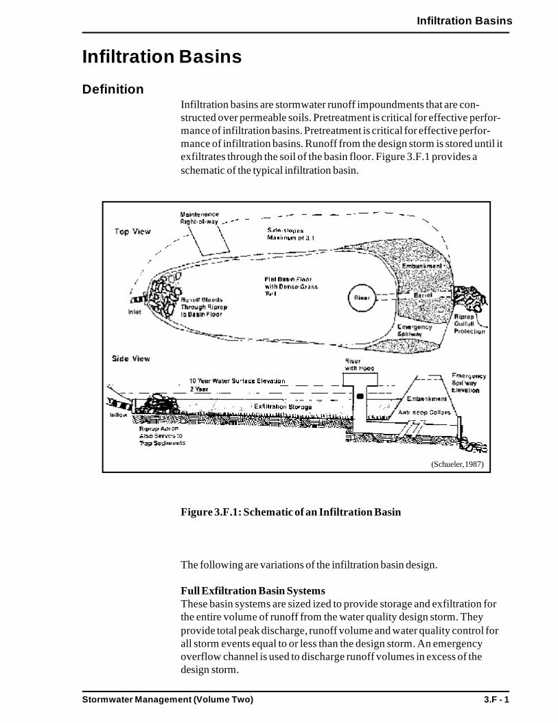
Stormwater Management (Volume Two) 3.F - 1
Infiltration Basins
Infiltration Basins
DefinitionInfiltration basins are stormwater runoff impoundments that are con-structed over permeable soils. Pretreatment is critical for effective perfor-mance of infiltration basins. Pretreatment is critical for effective perfor-mance of infiltration basins. Runoff from the design storm is stored until itexfiltrates through the soil of the basin floor. Figure 3.F.1 provides aschematic of the typical infiltration basin.
Figure 3.F.1: Schematic of an Infiltration Basin
The following are variations of the infiltration basin design.
Full Exfiltration Basin SystemsThese basin systems are sized ized to provide storage and exfiltration forthe entire volume of runoff from the water quality design storm. Theyprovide total peak discharge, runoff volume and water quality control forall storm events equal to or less than the design storm. An emergencyoverflow channel is used to discharge runoff volumes in excess of thedesign storm.
(Schueler, 1987)

3.F - 2 Stormwater Management (Volume Two)
Infiltration Basins
Partial or Off-line Exfiltration Basin SystemsPartial basin systems exfiltrate a portion of the runoff (usually the first flushor the first half inch), while the remaining runoff is conveyed to otherBMPs. The use of a flow splitter or weir diverts the first flush into theinfiltration basin. This design is useful at sites where exfiltration cannot beachieved by downstream detention BMPs because of site condition limita-tions.
PurposeTo collect and store the runoff from a specific design storm and allowexfiltration of this runoff.
To remove soluble and particulate pollutants.
To provide groundwater recharge, reduce runoff volume and reducepeak discharge.
AdvantagesProvides groundwater recharge.
Reduces local flooding.
Preserves the natural water balance of the site.
DisadvantagesHigh failure rates due to improper siting, design and lack of mainte-nance.
Restricted to fairly small drainage areas.
Depending on soil condition and aquifer susceptibility, a slight risk ofgroundwater contamination exists.
Not appropriate for treating significant loads of sediment and otherpollutants.
Requires frequent maintenance.
ApplicabilityThe application of infiltration basins is restricted by numerous site factorsincluding, soils, slope, depth to water table, depth to bedrock or imperme-able layer, contributing watershed area, proximity to wells, surface waters,foundations, and others. The recommended site criteria for infiltrationbasins are listed in Table 3.F.1.
Generally, infiltration basins are suitable to sites with gentle slopes, perme-able soils, relatively deep bedrock and groundwater levels, and a contribut-ing watershed area of approximately 2 to 15 acres.

Stormwater Management (Volume Two) 3.F - 3
Infiltration Basins
Infiltration basins should are not appropriate for areas which contributehigh concentrations of sediment, or suspended solids, without adequatepretreatment.
With these considerations in mind, the most efficient way to encourageinfiltration and reduce pollutant loadings in a cost efficient manner is toseparate contaminated runoff from uncontaminated runoff. Uncontami-nated stormwater runoff may be infiltrated directly, while contaminatedrunoff (such as from roads, parking areas and driveways) must be collectedand treated using an appropriate BMP or BMP combination, and thensubsequently routed (after treatment) back into infiltration facilities. In thismanner, the infiltration facilities perform double-duty: 1) they infiltrateuncontaminated stormwater during and immediately following the stormevent, and 2) they provide infiltration for pretreated stormwater frompolluted areas following an appropriate detention/treatment time for theselected design.
EffectivenessTable 3.2 shows the range of pollutant removal efficiencies for infiltrationbasins. When if the infiltration basin is well planned, designed, constructed,and maintained, then the reduction of pollutant loadings should be at thehigh end of the reported values. With pretreatment and adequate mainte-nance, infiltration basins can be used to meet the stormwater quality stan-dards.
Infiltration basins are not intended to remove coarse particulate pollutants;these must be removed by a pretreatment device before they enter thebasin. The pollutant removal efficiency of the basin is dependent upon howmuch runoff is exfiltrated by the basin.
Infiltration basins have limited capabilities for controlling peak discharge.Generally, it is not feasible, physically or economically, to provide storagefor large infrequent storms, such as the 100-year storm. Infiltration basinscan control peak discharges to pre-development levels for the design andsmaller storms, however. Like all infiltration systems, infiltration basins arevaluable in reducing the runoff volume from a site.
Planning ConsiderationsSites must be carefully evaluated before planning infiltration basins. Soils,depth to bedrock, and depth to water table must be investigated. Suitableparent soils should have a minimum percolation rate of 0.5 inches per hour.
Slopes of the contributing drainage area should not be steep and generallyshould not exceed five percent.
Pretreatment (water quality inlets or sump pits, swales with check dams, orsediment forebays/traps) should be a fundamental component of any BMPsystem relying on infiltration. In many cases, to perform as designed and to
3.F - 4 Stormwater Management (Volume Two)
Infiltration Basins
achieve the expected pollutant removal rates, engineered stormwatercontrols require pretreatment. Infiltration BMPs, for instance, have poorperformance and high failure rates due to clogging from sediments, andtherefore require pretreatment of stormwater in order to remove as muchof the suspended solids as possible before entering the system. It is impor-tant to note that this general practice applies also when infiltrating rooftoprunoff, even though in most cases it is presumed to be uncontaminated. It isa practical decision to implement some form of pretreatment to removesediments, leaf litter, and debris. This pretreatment will help to ensure theproper functioning of the infiltrating facility and allow for longer periodsbetween maintenance. Some examples of pretreatment controls includewater quality inlets, vegetated drainage systems, and sediment traps. Thesecontrols, when designed properly, may remove some 25-30% of sedimentloads. These pretreatment controls alone will not suffice to meet the 80%standard.
Designs for infiltration basins should emphasize accessibility and ease ofmaintenance
The use of infiltration methods for stormwater management should becautioned in recharge areas of groundwater drinking water supplies. Theseis a potential risk of groundwater contamination from polluted runoff.
DesignSee the following for complete design references:
Stormwater Infiltration. 1994. Ferguson. CRC Press. 2000 CorporateBlvd. NW, Boca Raton, FL. 33431.
Standards and Specifications for Infiltration Practices. 1984. MarylandDept. of Environment. Baltimore, MD.
Infiltration basins should be provided with a sediment forebay or anotherpretreatment device designed to capture coarse particulate pollutants, andwhere necessary, oil and grease, from the contributing watershed.
Site conditions must be investigated. Infiltration basins must have a mini-mum separation from seasonal high groundwater or bedrock of 2 feet.
To prevent incoming flow velocities from reaching erosive levels, whichcan scour the basin floor, inlet channels to the basin should be stabilized.Riprap may be used for this purpose. The riprap should be designed toterminate in a broad apron, which spreads the runoff more evenly over thebasin surface to promote better infiltration.
The required storage volume of an infiltration basin is the sum of thequantity of runoff entering the basin from the contributing area and theprecipitation directly entering the basin.

Stormwater Management (Volume Two) 3.F - 5
Infiltration Basins
Soil infiltration rates should be determined by specific samples at thelocation of the basin. One soil boring for every 5,000 feet of basin area isrecommended, with a minimum of three borings for each infiltration basin.Borings should be taken at the actual location of the proposed infiltrationbasin so that any localized soil conditions are detected. The design of theinfiltration basin should be based on the slowest rates obtained from theinfiltration tests performed at the site. The minimum acceptable final soilinfiltration rate is 0.5 inches per hour.
A storage time of 72 hours is recommended. Forty eight hours is recom-mended as the minimum storage time.
The bottom of the basin should be graded as flat as possible to provideuniform ponding and exfiltration of the runoff across the floor. Enhanceddeposition of sediment in low areas may clog the surface soils, resulting inreduced infiltration and wet areas. The side slopes of the basin should beno steeper than 3:1 (horizontal: vertical), to allow for proper vegetativestabilization, easier mowing, easier access, and better public safety.
Immediately following basin construction, the bottom and side slopes ofthe basin should be stabilized with a dense turf of water tolerant grass. Useof low maintenance, rapidly germinating grasses, such as fescues and reedcanary grass, are recommended. During the first two months, the newlyestablished vegetation should be inspected several times to determine if anyremedial actions (reseeding, irrigation, etc.) are necessary. Trees and shrubsshould not be planted within the basin or on the impounding embankments,in order to reduce the chance of basin failure due to root decay or subsur-face disturbance. The root penetration and thatch formation of the turfmaintains and may enhance the original infiltration capacity. Soluble nutri-ents are taken up by the turf for growth, improving the pollutant removalcapacity. The dense turf will impede soil erosion and scouring of the basinfloor.
In place of turf, a basin liner of 6 to 12 inches of fill material, such ascoarse sand, may be used. This material can be cleaned or replaced asneeded. Loose stone, riprap, and other irregular materials requiring handremoval of debris and weeds should not be used.
Embankments and spillways should be designed to conform with theregulatory guidelines of the state’s Office of Dam Safety (302 CMR 10.00).All infiltration basins must have an emergency spillway capable of bypass-ing runoff from large storms without damage to the impounding structure.
Vegetative buffers around the perimeter of the basin are recommended forerosion control and additional sediment and nutrient removal.

3.F - 6 Stormwater Management (Volume Two)
Infiltration Basins
ConstructionThe minimum construction criteria for infiltration basins are presented inTable 3.D.1. Care should be taken during construction to minimize the riskof failure of the infiltration basin.
Infiltration basins should never be used as temporary sediment traps forconstruction activities.
Light earth-moving equipment should be used to excavate the infiltrationbasin. Use of heavy equipment causes compaction of the soils beneath thebasin floor and side slopes, resulting in reduced infiltration capacity. Sincesome compaction of soils will occur during construction, the basin floorshould be deeply tilled with a rotary tiller or a disc harrow to restoreinfiltration rates after final grading.
Proper erosion/sediment control should be utilized during construction.
Immediately following basin construction, the floor and side slopes of thebasin should be stabilized with a dense turf of water tolerant grass. Use oflow maintenance, rapidly germinating grasses, such as fescues and reedcanary grass, are recommended.
MaintenanceAs infiltration basins are prone to failure due to the clogging of poroussoils, it is imperative that aggressive maintenance plans and schedules bedeveloped and implemented for these BMPs. The use of pretreatmentBMPs will significantly minimize maintenance requirements for the basin.
Preventive maintenance should be performed at least twice a year, andideally sediment should be removed from pretreatment BMPs after everymajor storm event.
Once the basin has gone online, inspections should occur after every majorstorm for the first few months to ensure proper stabilization and function.Attention should be paid to how long water remains standing in the basinafter a storm; standing water within the basin 48 to 72 hours after a stormindicates that the infiltration capacity may have been overestimated. Fac-tors responsible for clogging (such as upland sediment erosion, excessivecompaction of soils and low spots) should be repaired immediately.
Thereafter, the infiltration basin should be inspected at least twice per year.Important items to check for include: differential settlement, cracking,erosion, leakage, or tree growth on the embankments, condition of riprap,sediment accumulation and the health of the turf.
At least twice a year, the buffer area, side slopes and basin bottom shouldbe mowed. Grass clippings and accumulated organic matter should beremoved to prevent the formation of an impervious organic mat. Trash and

Stormwater Management (Volume Two) 3.F - 7
Infiltration Basins
debris should also be removed at this time. Deep tilling can be used tobreak up a clogged surface area. Any tilled areas should be revegetatedimmediately.
Sediment should be removed from the basin as necessary. Removal proce-dures should not take place until the floor of the basin is thoroughly dry.Light equipment, which will not compact the underlying soil, should beused to remove the top layer. The remaining soil should be deeply tilled,and revegetated as soon as possible. Pretreatment devices associated withbasins should be inspected and cleaned at least twice a year, and ideallyevery other month.
Summary: Infiltration Basin Guidelines
Site CriteriaThe contributing drainage area to any individual infiltration basinshould be restricted to 15 acres or less.
The minimum depth to the seasonal high water table, bedrock, and/orimpermeable layer should be 2 feet from the bottom of the basin.
The minimum acceptable soil infiltration rate should be 0.5 inches perhour. Maximum soil infiltration rates should not exceed 2.4 inches perhour to ensure adequate pollutant removal.
One soil sample for every 5,000 feet of basin area is recommended,with a minimum of three samples for each infiltration basin. Samplesshould be taken at the actual location of the proposed infiltration basinso that any localized soil conditions are detected.
Infiltration basins should not be used at sites where soils have 30% orgreater clay content, or 40% or greater silt clay content.
Infiltration basins should not be placed over fill materials.
The following setback requirements should apply to infiltration basininstallations:
-- Distance from any slope greater than 15% - a minimum of50 feet.
-- Distance from any septic system component - a minimum of100 feet.
-- Distance from any private well - a minimum of 100 feet,additional setback distance may be required depending onhydrogeological conditions.
3.F - 8 Stormwater Management (Volume Two)
Infiltration Basins
-- Distance from any public groundwater drinking supply wells- Zone I radius, additional setback distance may be requireddepending on hydrogeological conditions.
-- Distance from any surface drinking water supply - Zone A,and 100 feet from tributaries.
-- Distance from any surface water of the Commonwealth(other than surface water supplies and their tributaries) - aminimum of 100 feet.
-- Distance from any building foundations - a minimum of 10feet downslope and 100 feet upslope.
Design CriteriaInfiltration basins should be provided with a sediment forebay oranother pretreatment device designed to capture coarse particulatepollutants, and, where necessary oil and grease. In addition, vegetativebuffers around the perimeter of the basin are recommended for erosioncontrol and additional sediment and nutrient removal.
To prevent incoming flow velocities from reaching erosive levels, whichcan scour the basin floor, inlet channels to the basin should be stabi-lized. Riprap may be used for this purpose. The riprap should be de-signed to terminate in a broad apron, which spreads the runoff moreevenly over the basin surface to promote better infiltration.
The design of the infiltration basin should be based on the slowest ratesobtained from the infiltration tests performed at the site.
The depth of the infiltration basin should be adjusted so that maximumdrain time is 72 hours for the total runoff volume, with a minimumretention time of 48 hours.
The floor of the basin should be graded as flat as possible for uniformponding and exfiltration of the runoff across the floor.
The side slopes of the basin should be no steeper than 3:1 (horizontal:vertical).
Embankments and spillways should be designed in conformance withthe state Office of Dam Safety regulations. All infiltration basins musthave an emergency spillway capable of bypassing runoff from largestorms without damage to the impounding structure.
The bottom and side slopes of the basin should be stabilized with adense turf of water tolerant grass. In place of turf, a basin liner of 6 to12 inches of fill material, such as coarse sand, may be used. Loose

Stormwater Management (Volume Two) 3.F - 9
Infiltration Basins
stone, riprap and other irregular materials requiring hand removal ofdebris and weeds should not be used.
Construction CriteriaBefore the development site is graded, the area of infiltration basinshould be roped off to prevent heavy equipment from compacting theunderlying soils.
Infiltration basins should not be used as temporary sediment trapsduring construction.
Infiltration basins should not be constructed until the entire contributingdrainage area has been stabilized.
During and after excavation, all excavated materials should be placeddownstream, away from the infiltration basin, to prevent redepositionduring runoff events. All excavated materials should be properlyhandled and disposed, during and after construction.
Light earth-moving equipment should be used to excavate the infiltra-tion basin. Use of heavy equipment causes compaction of the soilsbeneath the basin floor and side slopes, resulting in reduced infiltrationcapacity. Since some compaction of soils will occur during construc-tion, the basin floor should be deeply tilled with a rotary tiller or a discharrow to restore infiltration rates, after final grading.
Maintenance CriteriaMaintenance is required for the proper operation of infiltration basins -plans for infiltration basins should identify owners, parties responsiblefor maintenance, and an inspection and maintenance schedule forinfiltration basins.
Infiltration basins should be inspected after every major storm for thefirst few months after construction to ensure proper stabilization andfunction. Thereafter, the basin should be inspected at least twice a year.
Pretreatment BMPs should be inspected and the accumulated sedimentremoved at least twice a year, ideally after every major rainfall event orevery other month.
The grass in the basin, on the sideslopes and in the buffer areas shouldbe mowed, and grass clippings, organic matter, and accumulated trashand debris removed, at least twice during the growing season.
Eroded or barren spots should be reseeded immediately after inspectionto prevent additional erosion and accumulation of sediment.

3.F - 10 Stormwater Management (Volume Two)
Infiltration Basins
Deep tilling can be used to break up a clogged surface area. Any tilledareas should be revegetated immediately.
Sediment should be removed from the basin as necessary. Removalprocedures should not take place until the floor of the basin is thor-oughly dry.

Stormwater Management (Volume Two) 3.G - 1
Dry Wells
Dry Wells
DefinitionDry wells are small excavated pits, backfilled with aggregate, and used toinfiltrate “good quality” stormwater runoff, such as uncontaminated roofrunoff. Dry wells are not to be used for infiltrating any runoff that could besignificantly contaminated with sediment and other pollutants, such asrunoff from high potential pollutant loading areas (as explained in Chapter2) and parking lot runoff. Figure 3.G.1 provides a schematic of a typicaldry well.
Figure 3.G.1: Schematic of a Dry Well
(Schueler, 1987)

Stormwater Management (Volume Two)3.G - 2
Dry Wells
PurposeTo infiltrate rooftop runoff.
To reduce the stormwater runoff volume to be treated by other BMPs.
AdvantagesCan be used at sites where storm drains are not available, or at any sitewhere it is acceptable and desirable to dispose of runoff in this manner.
Can result in a reduction in the size and cost of downstream BMPs and/or storm drains.
Can be utilized in retrofit areas where space is limited and whereadditional runoff control is necessary.
Can provide groundwater recharge for uncontaminated rooftop runoff.
DisadvantagesNot intended for general stormwater runoff quantity or quality control,and therefore has limited applicability.
May experience high failure rate due to clogging.
Only applicable in small drainage areas of one acre or less.
ApplicabilityThe use of dry wells is limited by a number of site constraints, includingsoil type, contributing drainage area, depth to bedrock, and depth togroundwater. The recommended minimum site criteria for dry wells arelisted in Table 3.G.1. Generally, dry wells should not be used alone but inconjunction with other BMPs to meet the Stormwater Management Stan-dards.
Runoff from high potential pollutant loading areas or contaminated rooftoprunoff should not be infiltrated.
Dry wells are intended to infiltrate roof runoff that is unlikely to contributesignificant loadings of sediment or pollutants. Dry wells are not to be usedfor infiltrating any runoff that could transport sediment and pollutants, suchas parking lot runoff and also are meant to be used only in areas wherethere are no significant sources of depositional air pollution.
Dry wells can be used in retrofit areas where space is limited and whereadditional runoff control is necessary. Use of dry wells can reduce thevolume of runoff from a site, thereby reducing the size and cost of down-stream stormwater control facilities.
Dry wells are applicable to sites where storm drains are not available.

Stormwater Management (Volume Two) 3.G - 3
Dry Wells
EffectivenessThese small systems can be effectively used to infiltrate rooftop runoff,thereby reducing flows to downstream BMPs or storm sewers and contrib-uting towards the treatment of the prescribed water quality runoff volume.When designed properly and coordinated with other BMPs, dry wells canhelp to manage peak discharges from design storms, reduce runoff volume,and provide good quality groundwater recharge.
Planning ConsiderationsThe minimum site criteria listed in Table 3.G.1 should be met in planningdry well installations.
Soils should have a minimum infiltration rate of 0.5 inches/hour and maxi-mum permeability of 5 inches/hour. Where soils exceed the maximum rate,water quality treatment should be provided prior to infiltration.
Dry wells are intended to infiltrate only rooftop runoff. Runoff that con-tains sediments and other pollutants should be directed away from the drywell, and controlled by another type of BMP.
DesignDry wells are basically a variation of the infiltration trench, designed toinfiltrate good quality runoff only. Roof top runoff is discharged to the drywell through the roof leader, which extends directly into a stone filledreservoir. Roof top gutter screens are needed to trap particles, leaves andother debris, and must be cleaned regularly. The dry well should be sited aminimum of 10 feet from the building foundation. Dry wells should not beconstructed until the drainage area has been stabilized.
Dry wells can be designed with a surface inlet to capture runoff from theupland drainage area. This is not recommended however, because extrememeasures must be taken to prevent sediment and pollutant loading fromcausing system failure or degradation of water quality. Dry wells designedwith surface inlets should have a minimum 20 foot vegetated filter strip oneach side of the inlet.
The volume and surface area of dry wells is a function of the quantity ofrunoff entering the dry well from the contributing area and the overlyingsoil, the void space and the infiltration rate. Since the dry well is filled withstone, only the space between the stone is available for runoff storage. Drywells are to be filled with 1.5 - 3.0 inch diameter, clean washed stone. Thissize stone will yield a void space of approximately 30 - 40%. The final soilinfiltration rate below the dry well is determined by the results of the soilsampling. At least one soil sample for each dry well is recommended.Samples should be taken at the actual location of the proposed dry wellthat any localized soil conditions are detected. The minimum acceptableinfiltration rate should be 0.5 inches per hour.
Stormwater Management (Volume Two)3.G - 4
Dry Wells
The maximum depth of the dry well can be determined from the infiltrationrate, the allowable storage time, and the void space. A maximum storagetime of 72 hours is recommended. Forty eight hours is recommended as theminimum storage time.
The bottom of the dry well must be at least two feet above the seasonalhigh water table and bedrock, and below the frost line.
Excavated material should be placed away from the excavated sides toincrease wall stability. Large roots should be trimmed flush with the sidesto prevent fabric puncturing or tearing during installation. Side wallsshould be roughened where sheared and sealed by heavy equipment.
An observation well should be installed to monitor the runoff clearancefrom the system. This well should consist of a well anchored, verticalperforated PVC pipe with a lockable above ground cap.
ConstructionThe minimum construction criteria for dry wells are presented in Table3.G.1. Care should be taken during construction to minimize the risk offailure of the dry well.
MaintenanceSince these structures are often installed at single family dwellings, it isimportant that developers outline the maintenance requirements to propertypurchasers clearly.
Dry wells should be inspected after every major storm in the first fewmonths after construction to ensure proper stabilization and function.Thereafter, the dry well should be inspected at least once per year. Waterdepth in the observation well should be measured at 0, 24, and 48 hourintervals after a storm. Clearance rates are calculated by dividing the dropin water level (inches) by the time elapsed (hr). A comparison of clearancerate measurements taken over the years provides a useful tool for trackingany clogging problems within the dry well.
Summary: Guidelines for Dry Wells
Site CriteriaThe contributing drainage area to a dry well should be restricted to oneacre or less.
The minimum depth to the annual mean high water table, bedrock, and/or impermeable layer should be two feet from the bottom of the drywell.
The minimum acceptable soil infiltration rate should be 0.5 inches perhour. The maximum rate is 5 inches per hour.

Stormwater Management (Volume Two) 3.G - 5
Dry Wells
One soil boring for each dry well is recommended. Borings should betaken at the actual location so that any localized soil conditions aredetected.
Not to be used at sites where soils have 30% or greater clay content, or40% or greater silt clay content.
Should not be placed over fill materials.
The following setback requirements should apply:
-- Distance from any slope greater than 15%: minimum of 50feet.
-- Distance from any septic system component: minimum of100 feet.
-- Distance from any private well: minimum of 100 feet,additional setback distance may be required depending onhydrogeological conditions.
-- Distance from any public groundwater drinking supplieswell: Zone I radius, additional setback distance may berequired depending on hydrogeological conditions.
-- Distance from any surface drinking water supply: Zone A,and 100 feet from tributaries.
-- Distance from any surface water of the Commonwealth(other than surface water supplies and their tributaries):minimum of 100 feet.
-- Distance from any building foundations: minimum of 10feet.
The depth should be adjusted so that maximum drain time is 72 hoursfor the total runoff volume, with a minimum retention time of 48 hours.
An observation well should be installed to monitor the runoff clearancefrom the system. This well should consist of a well anchored, verticalperforated PVC pipe with a lockable above ground cap.
Construction CriteriaBefore the development site is graded, the area for the dry well shouldbe roped off to prevent heavy equipment from compacting the underly-ing soils.
Stormwater Management (Volume Two)3.G - 6
Dry Wells
Diversion berms should be placed around the perimeter during allphases of construction. Sediment and erosion controls should be usedto keep runoff and sediment away from the dry well area.
During and after excavation, all excavated materials should be placeddownstream, away from the dry well, to prevent redeposition of thesematerials during runoff events. All excavated materials should beproperly handled and disposed, during and after construction.
Light earth-moving equipment should be used for excavation. Use ofheavy equipment causes compaction of the soils beneath the dry wellfloor, resulting in reduced infiltration capacity.
Once excavated, the top, sides and bottom should be lined withgeotextile fabric (filter fabric). The geotextile fabric must be selected toensure compatibility with the surrounding soil textures and applicationpurposes. The cut width of the filter fabric must include sufficientmaterial to include a minimum 12 inch overlap. Place the fabric rollover the dry well, and unroll sufficient length to allow placement of thefabric down into the dry well. When overlaps are required betweenrolls, the upstream roll must lap a minimum of two feet over the down-stream roll to provide a shingled effect. The bottom of the dry well canbe covered with a six to twelve inch layer of clean sand (VDOT FineAggregate-Grading A or B) in place of filter fabric.
Fill with 1.5 - 3.0 inch diameter, clean washed stone only. The stoneshould be placed in the dry well in lifts and lightly compacted with platecompactors to form the coarse base.
Maintenance CriteriaMaintenance is required for the proper operation; plans should identifyowners, parties responsible for maintenance, and an inspection andmaintenance schedule.
Inspect the dry well after every major storm for the first few months toensure proper stabilization and function. Thereafter, inspect them atleast once per year. Water levels in the observation well should berecorded over several days to check the dry well drainage.

Stormwater Management (Volume Two) 3.H - 1
Sand Filters/Organic Filters
Sand Filters/Organic Filters
DefinitionAlso known as filtration basins, sand and organic filters consist of selfcontained beds of sand or peat (or combinations of these and other materi-als) either underlain with perforated underdrains or designed with cells andbaffles with inlets/outlets. Stormwater runoff is filtered through the sand,and in some designs may be subject to biological uptake. Runoff is dis-charged or conveyed to another BMP for further treatment. Where thepotential for groundwater contamination is low and proper soils arepresent, the treated runoff may be allowed to exfiltrate into the subsoil.Figure 3.H.1 provides a schematic of the typical sand filter.
Figure 3.H.1: Schematic of an Organic Filter
A number of designs currently are available for sand filters. Organic filtersutilize layers of peat, limestone, and/or topsoil to improve pollutant re-moval rates; designs may also feature wetland vegetation or grass cover.Sand filters have also been designed as trench systems to receive and treatparking lot runoff, and have been used in place of water quality inlets.
Stormwater Management (Volume Two)3.H - 2
Sand Filters/Organic Filters
PurposeTo control stormwater runoff quality, by utilizing filtration, (in somecases infiltration and/or biological uptake), in order to provide highremoval of sediment and trace metals, and moderate removal of nutri-ents, BOD and coliform bacteria.
Depending on design, can provide groundwater recharge, reduce runoffvolume, and reduce peak discharge.
AdvantagesApplicable in small drainage areas of 1 to 10 acres; although somedesigns may accept runoff of up to 50 acres.
Have few constraints; therefore, can be applied to most developmentsites.
Good retrofit capability.
Longevity of sand filters is high.
Flexibility to provide groundwater recharge if conditions and situationsallow.
DisadvantagesPretreatment required to prevent the filter media from clogging.
Frequent maintenance required.
Relatively costly to build and install.
Without grass cover, the surface of sand filters can be extremely unat-tractive.
May have odor problems, which can be overcome with design andmaintenance.
ApplicabilitySand filters are very adaptable, and have few site constraints. They can beapplied to in areas with thin soils, high evaporation rates, low soil infiltra-tion rates and limited space.
Sand filters can be used in ultra-urban sites with small drainage areas thatare completely impervious (such as small parking lots and fast food restau-rants). They can be applicable to many areas that are difficult to retrofit dueto space limitations.

Stormwater Management (Volume Two) 3.H - 3
Sand Filters/Organic Filters
Sand filters that are not designed to exfiltrate into the subsoil, but can beapplied to areas with poor soil infiltration rates, where groundwater con-cerns restrict the use of infiltration, or for high pollutant loading areas.
Sand filters are designed as off-line BMPs; they are intended primarily forquality control not quantity control. A diversion structure, such as a flowsplitter or weir, is provided to route a portion of the runoff into the sandfilter, while the remainder continues on to a stormwater quantity controlBMP. With careful design, or a number of units, peak discharge rates maybe controlled.
Because of the potential for clogging, sand filters should only be applied tosites that have been stabilized, and should never be used as sedimentationtraps or basins during construction. Any disturbed areas within the sandfilters drainage area should be identified and stabilized to the maximumextent possible.
EffectivenessTable 5.2 shows the range of pollutant removal efficiencies for sand filters.When the sand filter is well planned, designed, constructed, and main-tained, then the reduction of the pollutant loadings should be at the highend of the reported values. Sand filters can be used to meet the stormwater quality standards.
Pollutant removal is achieved primarily by straining pollutants through thefiltering media and by settling on top of the sand bed and/or in a pretreat-ment basin. Organic filters may have slightly higher pollutant removal ratesdue to the adsorptive properties of peat. Designs with grass cover orwetland vegetation can provide additional nutrient removal by plant up-take.
Sand filters are designed for water quality control, and generally not forquantity control. Some sand filters that are designed to exfiltrate to thesubsoil will provide runoff volume reduction and can aid in meeting volumecontrol requirements.
Sand filters can be used with downstream quantity control structures tomeet both the storm water quality and quantity standards.
Planning ConsiderationsThe surface of sand filters can be unattractive, and therefore, may not beappropriate for residential areas without a grass cover. Odors may also be aproblem with sand filters.
To avoid clogging, sand filters should only be applied to sites that havebeen stabilized, and should never be used as sedimentation basins duringconstruction. Any disturbed areas within the sand filters drainage area

Stormwater Management (Volume Two)3.H - 4
Sand Filters/Organic Filters
should be identified and stabilized to the maximum extent possible. Gener-ally, sand filters should be located off-line from primary conveyance/detention systems and should be preceded by a pretreatment device.
As previously mentioned, sand filters are generally designed as off-lineBMPs because they are intended primarily as stormwater quality control.Sand filters should be sized for the water quality design storm and storm-water conveyance should be fitted with flow splitters or weirs to routedesign runoff to the sand filter. Excess runoff bypasses the sand filter andcontinues to another quantity BMP. In cases where designs and site condi-tions allow for infiltration into the subsurface, some quantity control maybe achieved through volume and rate reductions.
DesignSee the following for complete design references:
Design of Stormwater Filtering Systems. 1996. Claytor. Center for water-shed Protection.
Biofiltration swale performance, recommendations and design consider-ations. 1992. Washington Department of Ecology: Publications Office.Mailstop PV-11, Olympia, WA. 98504-8711.
Design guidelines for water quality control basins. 1988. City Of Austin(TX). Environmental Resources Management Division.
Design of peat sand filters: A proposed stormwater management practice.1990. Galli. MWCOG Information Center.
Two key design principles should apply: the first is visibility; the second issimplicity. A visible sand filter is more apt to adequately maintained andoperated. Complex designs are more expensive and difficult to operate andmaintain.
Typically, sand filter systems are designed with two components, a pre-treatment sedimentation component and a filtering component. The sedi-mentation component is a presettling basin or vegetated swale, designed toreduce the sediment load to the filtering component. Presettling also slowsthe runoff velocity and spreads it evenly across the top of the filter compo-nent. Generally, the volume of the pretreatment basin should be equal to orgreater than the filtering capacity. The filtering component is designed tocapture the finer silt and clay particles and other pollutants in the runoff.
Sand filters are designed to function as a stormwater quality control prac-tice, and not to provide detention for downstream areas. Therefore, theyshould be located to be off-line systems, away from the primary convey-ance/detention system.

Stormwater Management (Volume Two) 3.H - 5
Sand Filters/Organic Filters
The pretreatment component should be designed to allow for the settling ofcoarse sediment that may clog the sand filter and reduce its effectiveness.
A design filtration rate of 2 inches/hour is recommended. This value is lowcompared to the published values for sand; however, it reflects actual ratesachieved by sand filters in urban areas.
The sand filter should be designed to completely drain in 24 hours or less.This drainage time is recommended as there is very little storm storageavailable in the sand filter.
Concrete structures are not always necessary for sand filters. Where siteconditions allow and infiltration is possible, lining the excavated pit ortrench with geotextile fabric may suffice and reduce costs. Where infiltra-tion is not possible, the sand filter structure must be constructed of imper-meable media, such as concrete.
Eighteen inches of 0.02-0.04 inch diameter sand (smaller sand is accept-able) is the recommended final thickness for the sand bed. Consolidation ofthe sand that is likely to occur during construction must be taken intoconsideration. The depth of the bed can be stabilized by wetting the sandperiodically, allowing it to consolidate, and then adding extra sand.
There are several possible sand bed configurations, most utilize a gravelbed at the bottom and then a layer sand and/or peat, leaf compost, ortopsoil/grass. In all configurations, the top surface layer of the bed shouldbe level to ensure equal distribution of the runoff in the bed.
The gravel bed layer is generally 4 to 6 inches of 1/2 to 2 inch diametergravel. The gravel and top media layers must be separated by a layer ofgeotextile fabric to prevent the sand from infiltrating into the gravel layerand the underdrain piping.
Ease of access for maintenance is an important consideration in sand filterdesigns. Some designs utilize a geotextile layer, surface screen, or gratingat the top to filter coarse sediment and debris and for ease of maintenance.The typical maintenance of the sand filter is to remove the top severalinches of discolored sand and replace this with clean media. Designs shouldallow for a maintenance worker to manually remove this material, byproviding ramps, manhole steps, or ringbolts. In addition, heavy grates ormanhole covers that cannot be lifted manually should be avoided.
The trench design has the lateral underdrain pipes that are covered with 1/2to 2 inch diameter gravel and geotextile fabric. The underdrains are under-lain with drainage matting, which is necessary to provide adequate hydrau-lic conductivity to the lateral pipes.

Stormwater Management (Volume Two)3.H - 6
Sand Filters/Organic Filters
The underdrain piping must be reinforced to withstand the weight of theoverburden. The minimum grade of the piping should be 1/8 inch per foot(at 1% slope). An impermeable liner (clay, geomembrane, concrete) may berequired under the filter to protect groundwater. If the impermeable liner isnot required, a geotextile liner should be installed, unless the bed has beenexcavated to bedrock.
Side slopes of earthen embankments should not exceed 3:1 (horizontal:vertical). Fencing around sand filters may be recommended for somedesigns to reduce safety hazards.
The careful selection of topsoil and sod for natural cover will help reducethe potential for failure. Sod with fine silts and clays will clog the top of thesand filter, however.
Maximum longevity of the sand filter may be achievable by limiting its useonly to impervious areas.
ConstructionThe minimum construction criteria for sand filters are presented in Table3.H.1. Sand filters should not be used as temporary sediment traps forconstruction.
Care should be taken during construction to minimize the risk of prematurefailure of the sand filter. Construction of the sand filters should take placeafter the site has been stabilized and sediment/erosion controls should beutilized during construction.
Consolidation of the sand or other filtration media is likely to occur duringor shortly after construction of the sand filter. The depth of the sand bed orother media layers can be adjusted properly by wetting the sand, allowing itto consolidate, and then adding addition media.
MaintenanceSand filters should be inspected after every major storm in the first fewmonths after construction to ensure proper function. Thereafter, the sandfilter should be inspected at least once every 6 months.
Sand filters require frequent manual maintenance. Raking of the sand andremoval of surface sediment, trash and debris are the primary maintenancetasks.
Eventually a layer of sediment will accumulate on the top of the sand. Thissediment can be easily scraped off using rakes or other devices. Finersediments will penetrate deeper into the sand over time, and replacement ofsome (several inches) or all of the sand will be necessary. Discolored sandis an indicator of the presence of fine sediments. Sand removed from thefilter component should be de-watered and then disposed properly.

Stormwater Management (Volume Two) 3.H - 7
Sand Filters/Organic Filters
Summary: Guidelines for Sand Filters
Site CriteriaThe typical drainage area served by sand filters is from 0.5 to 10 acres.Depending on design, the contributing drainage area may be up to 50acres.
Depending on soil types, sand filters may be designed to exfiltrate all ora portion of treated runoff. Caution should be used in recharge areas ofpublic drinking water supplies.
Design CriteriaSand filters should be preceded by pretreatment to allow for the settlingof coarse sediment that may clog the sand filter and reduce its effective-ness.
Generally, sand filters are designed to function as a storm water qualitycontrols, and not to provide detention for downstream areas. There-fore, they should be designed as off-line components from the primaryconveyance/detention system.
A design filtration rate of 2 inches/hour is recommended.
The sand filters should be designed to completely drain in 24 hours orless.
Eighteen inches of 0.02-0.04 inch diameter sand (smaller sand is ac-ceptable) is recommended for the sand bed. 4 to 6 inches of gravel isrecommended for the bed of the filter.
Designs using a geotextile layer, surface screen, or a grating at the topare recommended to filter coarse sediment and debris and for ease ofmaintenance.
The careful selection of topsoil and sod for natural cover will helpreduce the potential for failure; sod with fine silts and clays will clogthe top of the sand filter.
Construction CriteriaDiversion berms should be placed around the perimeter of the sandfilters during all phases of construction. Sediment and erosion controlsshould be used to keep runoff and sediment away from the dry wellarea.
Sand filters should not be used as temporary sediment traps for con-struction activities.
Stormwater Management (Volume Two)3.H - 8
Sand Filters/Organic Filters
Consolidation of material in the sand filters during construction must betaken into consideration. The depth of the bed can be stabilized bywetting the sand periodically, allowing it to consolidate, and thenadding extra sand.
During and after excavation, all excavated materials should be placeddownstream, away from the sand filters, to prevent redeposition duringrunoff events. All excavated materials should be handled properly anddisposed, during and after construction.
Maintenance CriteriaMaintenance is required for the proper operation of sand filters; plansfor sand filters should identify owners, parties responsible for mainte-nance, and an inspection and maintenance schedule.
Sand filters should be inspected after every major storm in the first fewmonths to ensure proper function. Thereafter, the sand filter should beinspected at least once every 6 months.
Sand filters require frequent manual maintenance, primarily raking ofthe sand and removal of surface sediment, trash, and debris.
Sediments, trash and debris should be removed from the from thepresettling basin on a regular basis to reduce the risk of clogging.
Replacement of the top several inches of sand should occur yearly, ormore frequently when drawdown does not occur within 36 hours afterthe presettling basin has emptied.

Stormwater Management (Volume Two) 3.I - 1
Water Quality Inlets/Deep Sump Catch Basins
Water Quality Inlets/Deep Sump Catch Basins
DefinitionDeep sump catch basins, known as oil and grease or hooded catch basins,and water quality inlets are underground retention systems designed toremove trash, debris, and some amount of sediment and oil and greasefrom stormwater runoff.
Figure 3.I.1 provides a schematic of the typical three chamber water qualityinlet. Figure 3.I.2 illustrates a deep sump catch basin.
In the water quality inlet, runoff enters the top of the first chamber, whichcontains a permanent pool of water (minimum depth of four feet). Pollut-ants are removed in this first chamber by trapping floatable debris (leavesand litter) and by gravity settling of sediment. Stormwater flows throughscreened orifices to the second chamber, which also contains a permanentpool of water (minimum depth of 4 feet). The stormwater must then passthrough the bottom opening of an inverted pipe into the third chamber. Theopening of this pipe is located at least three feet below the second chamberpermanent pool. Oil and grease float on the permanent pool water, and aretrapped in the second chamber. Eventually the oil and grease will attach tosediment and settle out. If the outlet of the third chamber is above thechamber floor, then a permanent pool will form, providing another settlingarea. Otherwise, there will be little pollutant removal in the third chamber.Lastly, stormwater is routed out of the third chamber into the storm drainsystem or into another BMP.
Figure 3.I.1: Schematic Design of a Water Quality Inlet
(Schueler, 1987)
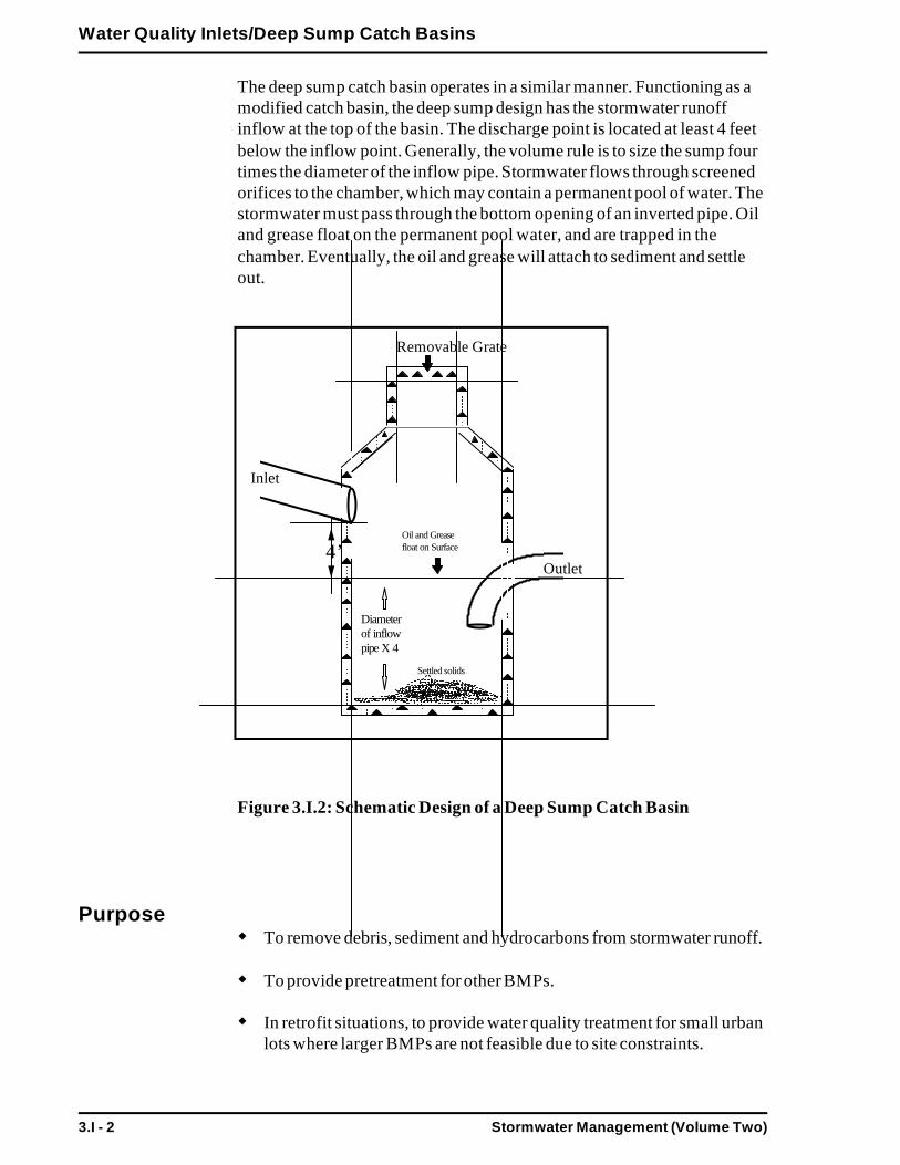
Stormwater Management (Volume Two)3.I - 2
Water Quality Inlets/Deep Sump Catch Basins
Inlet
Outlet
Oil and Greasefloat on Surface4’
Removable Grate
Settled solids
Diameterof inflow pipe X 4
The deep sump catch basin operates in a similar manner. Functioning as amodified catch basin, the deep sump design has the stormwater runoffinflow at the top of the basin. The discharge point is located at least 4 feetbelow the inflow point. Generally, the volume rule is to size the sump fourtimes the diameter of the inflow pipe. Stormwater flows through screenedorifices to the chamber, which may contain a permanent pool of water. Thestormwater must pass through the bottom opening of an inverted pipe. Oiland grease float on the permanent pool water, and are trapped in thechamber. Eventually, the oil and grease will attach to sediment and settleout.
Figure 3.I.2: Schematic Design of a Deep Sump Catch Basin
PurposeTo remove debris, sediment and hydrocarbons from stormwater runoff.
To provide pretreatment for other BMPs.
In retrofit situations, to provide water quality treatment for small urbanlots where larger BMPs are not feasible due to site constraints.

Stormwater Management (Volume Two) 3.I - 3
Water Quality Inlets/Deep Sump Catch Basins
AdvantagesUsually located underground, so limited lot size is not a deterrent.
Compatible with storm drain systems.
Can be used for retrofitting small urban lots where larger BMPs are notfeasible.
Provides pretreatment of runoff before it is delivered to other BMPs.
Easily accessed for maintenance.
Longevity is high, with proper maintenance.
DisadvantagesLimited pollutant removal.
Expensive to install and maintain, resulting in high cost per unit areatreated.
No volume control.
Frequent maintenance is necessary.
Proper disposal of trapped sediment and oil and grease.
ApplicabilityWater quality inlets and deep sumps are applicable to parking lots, gasstations, convenience stores, and other areas with substantial vehiculartraffic. Generally the contributing area contains a large portion of impervi-ous cover that is expected to receive high sediment and hydrocarbonloadings. It is recommended that the contributing area to any individualinlet be limited to one acre or less of impervious cover. Multiple inlets canbe used for larger impervious areas, before routing excess stormwaterflows to other BMPs. Water quality inlets and deep sumps are recom-mended as pretreatment devices only.
EffectivenessThe range of pollutant removal efficiencies for water quality inlets and deepsumps is provided in the Stormwater Policy (Volume 1, Chapter 1). Sincethey have limited storage capacity, detention time, and pollutant removal,water quality inlets and deep sump, catch basins cannot be used alone tomeet Stormwater Management Standards. Therefore, these BMPs shouldonly be used as pretreatment devices for other technologies.
Stormwater Management (Volume Two)3.I - 4
Water Quality Inlets/Deep Sump Catch Basins
As pretreatment devices, water quality inlets and deep sumps can beeffective in removing sediments and oil and grease that may impair theoperation of other BMPs, provided that they are designed and maintainedproperly.
Water quality inlets and deep sumps rely primarily on settling for pollutantremoval. Because of the small storage capacity and brief retention time,only coarse sediments are likely to be trapped. In addition, resuspension ofthe sediments is likely, unless an aggressive maintenance program is fol-lowed. The current inlet designs have low to moderate removal rates forparticulate pollutants, and zero to low removal of soluble pollutants.Moderate hydrocarbon removal can be expected because of their strongaffinity to adsorb onto sediment.
Pollutants are not actually removed from water quality inlets or sumps untilthey are cleaned out. Regular maintenance is required to reduce the risk ofresuspension of sediments during large storm events.
Planning ConsiderationsBecause of their limited pollutant removal and storage capacity, waterquality inlets and deep sumps should be considered only for pretreatmentapplications or as a last alternative. Inlets are able to prolong the effective-ness of larger BMPs such as detention, retention, or infiltration basinswhich have sedimentation problems. Inlets and sumps are most frequentlyused in ultra-urban areas where space or storage are not available for moreeffective BMPs.
Provisions need to be made for frequent cleaning and inspection. Generally,ordinary catch basin cleaning equipment (vacuum pumps available to mostpublic works departments) can be used to clean water quality inlets.Manual removal of sediments may be necessary, as well.
Catch basin materials often include various concentrations of oil andhazardous materials such as petroleum hydrocarbons and metals. Catchbasin cleanings are classified as solid waste by DEP and must be handledand disposed in accordance with all DEP regulations, policies, and guid-ance. In the absence of written approval from the DEP, catch basincleanings must be taken to a facility permitted by the DEP to accept solidwaste. Catch basin cleanings may be disposed at any landfill that is permit-ted by the DEP to accept solid waste. Materials containing free drainingliquids are prohibited from being accepted at landfills.
The DEP encourages beneficial reuse of this material whenever possible.However, any use of the material outside a landfill requires a BeneficialReuse Determination from the DEP.
A secondary concern is the pulse loading of trapped residuals during longerstorm events due to resuspension of sediments.

Stormwater Management (Volume Two) 3.I - 5
Water Quality Inlets/Deep Sump Catch Basins
Longevity of the systems is high, and standardized designs allow for rela-tively easy installation. Compared to other BMPs, water quality inlets aremoderately expensive.
DesignWater quality inlets and deep sump catch basins should be designed andconstructed as off-line systems only. Runoff in excess of the prescribedwater quality treatment volume should be routed around (bypass) thepretreatment BMP.
The inflow pipe should be sized and constructed to pass the design stormvolume into the water quality inlet or deep sump, and excess flows shouldbe directed to another BMP of sufficient capacity to meet the water quan-tity requirements or to a storm drain system. An off-line design shouldenhance pollutant removal.
To achieve consistent removal of pollutants, the volume of the permanentpools in the chambers of the inlets should be maximized. The combinedvolume of these pools should equal at least 400 cubic feet per acre ofcontributing impervious area. The pools should be at least four feet deepfor settleability. Where feasible, the third chamber should also be used as apermanent pool. Vertical baffles at the bottom of the permanent pools canhelp to minimize sediment resuspension.
To keep out floatables, a trash rack or screen should cover the dischargeoutlets. To trap hydrocarbons in the water quality inlets, an inverted elbowpipe should be located between the second and third chambers and thebottom of the pipe should be at least three feet below the second chamberpermanent pool. For deep sumps, the four times sizing rule (i.e. depthequals 4X pipe diameter) must be followed. Manholes should be includedfor each chamber to provide access for cleaning.
MaintenanceThe actual removal of sediments and associated pollutants and trash occursonly when inlets or sumps are cleaned out; therefore, regular maintenanceis required. Most studies have linked the failure of inlets to the lack ofregular maintenance. The more frequent the cleaning, the less likely sedi-ments will be resuspended and subsequently discharged. In addition,frequent cleaning also results in more volume available for future stormsand enhances the overall performance. Ideally, in areas of high sedimentloading, inlets should be inspected, and cleaned, after every major stormevent. At a minimum, water quality inlets and deep sumps should becleaned four times per year (although one study found maximum benefitsfrom monthly cleaning), and inspected monthly. Disposal of the accumu-lated sediment and hydrocarbons must be in accordance with applicablelocal, state, and federal guidelines and regulations.

Stormwater Management (Volume Two)3.I - 6
Water Quality Inlets/Deep Sump Catch Basins
Summary: Guidelines for Water Quality Inlets and Deep Sumps
Site CriteriaThe contributing drainage area to any individual inlet or sump shouldbe one acre or less of impervious area.
Design CriteriaInlets and sumps are recommended as pretreatment devices only, andshould not be used as primary BMPs.
The volume of the permanent pools in the chambers should be maxi-mized - the combined volume of pools should equal at least 400 cubicfeet per acre of contributing impervious area.
The minimum depth of the permanent pools should be four feet.
A trash rack or screen should cover the discharge outlets (includingbetween the chambers).
For inlets, the bottom of the elbow pipe connecting the second andthird chambers should be at least three feet below the second chamberpermanent pool.
The inflow pipe should be sized and constructed to pass the waterquality design storm volume into the inlet, and excess flows should bedirected to another BMP.
Manholes should be included for each chamber to provide access forcleaning.
Maintenance CriteriaMaintenance is essential for the proper operation of water quality inlets- plans should identify owners, parties responsible for maintenance, andan inspection and maintenance schedule.
Inlets should be cleaned a minimum of four times per year and in-spected monthly.
All sediments and hydrocarbons should be properly handled and dis-posed, in accordance with local, state and federal guidelines and regula-tions.
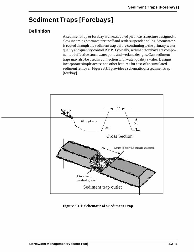
Stormwater Management (Volume Two) 3.J - 1
Sediment Traps [Forebays]
Sediment Traps [Forebays]
DefinitionA sediment trap or forebay is an excavated pit or cast structure designed toslow incoming stormwater runoff and settle suspended solids. Stormwateris routed through the sediment trap before continuing to the primary waterquality and quantity control BMP. Typically, sediment forebays are compo-nents of effective stormwater pond and wetland designs. Cast sedimenttraps may also be used in connection with water quality swales. Designsincorporate simple access and other features for ease of accumulatedsediment removal. Figure 3.J.1 provides a schematic of a sediment trap[forebay].
Figure 3.J.1: Schematic of a Sediment Trap
Cross Section
4’
67 cu.yd./acre
3:1
Length (in feet)= 6X drainage area (acres)
5.0’
1 to 2 inchwashed gravel
Sediment trap outlet
Stormwater Management (Volume Two)3.J - 2
Sediment Traps [Forebays]
PurposeTo pretreat for removal of debris, sediment and associated pollutantsfrom stormwater, before another BMP technology.
AdvantagesCompatible with a wide array of BMPs.
Can be used to expand existing BMPs, especially pond and wetlandsystems.
Provide pretreatment of runoff before delivery to other BMPs.
Slows velocities of incoming stormwater.
Easily accessed for sediment removal.
Longevity is high with proper maintenance.
DisadvantagesLimited pollutant removal.
No removal of soluble pollutants.
No volume control.
More space required than water quality inlets and deep sumps.
Frequent maintenance is necessary.
Proper disposal of trapped sediment and oil and grease.
ApplicabilitySediment traps and forebays are widely applicable and can be used withmost other BMP technologies. Sediment forebays are widely used inconnection with pond and wetland designs. Sediment traps may consumemore space than water quality inlets or deep sump catch basins. The vol-ume of the forebay is generally a minimum of 0.1 inch per contributingacre.
EffectivenessThe range of pollutant removal efficiencies for sediment traps and forebaysis in the Stormwater Management Policy (Volume 1, Chapter 1). Since theyhave limited storage capacity, detention time and pollutant removal, sedi-ment raps cannot be used alone to meet the stormwater performancestandards. Therefore, these BMPs should be used only as pretreatmentdevices for other technologies.
Stormwater Management (Volume Two) 3.J - 3
Sediment Traps [Forebays]
As pretreatment devices, sediment traps can be effective in removingsediments and oil and grease that may impair the operation of other BMPs,provided that they are designed and maintained properly.
Sediment traps rely primarily on settling for pollutant removal. Because ofthe relatively small storage capacity and brief retention times, only coarsesediments are likely to be trapped. Resuspension of the sediments is likely,unless an aggressive maintenance program is followed.
Pollutants are not actually removed from sediment traps until they arecleaned out. Regular maintenance is required to reduce the risk ofresuspension of sediments during large storm events.
Planning ConsiderationsSediment traps should be considered only for pretreatment applications,because of their limited pollutant removal and storage capacity. Traps aremost frequently used in connection with pond and wetland BMPs.
Provisions need to be made for frequent cleaning and inspection. Sedimenttraps and forebays are designed for ease of maintenance.
Provisions should be made for the handling and disposal of trapped sedi-ments and hydrocarbons removed from the traps. A secondary concern isthe pulse loading of trapped materials during longer storm events due toresuspension of sediments.
Longevity of the systems is high, and standardized designs allow for easyinstallation. Relative to other BMPs, sediment traps are inexpensive.
DesignSediment traps are typically on-line units, designed to slow stormwaterrunoff and settle sediments. Volume sizing should be for the prescribedwater quality volume, at a minimum, and can accommodate the 2 and 10year storms. Sediment traps should be designed for 0.1 inch/acre.
Sediment traps and forebays should incorporate design features to makemaintenance accessible and easy. Concrete floors or pads make shovelingaccumulated sediment very easy. If machinery is to be utilized, accessshould be planned carefully and included in the design. Sediment forebaysmay require excavation; therefore, concrete flooring may not be appropri-ate. A sediment depth marker makes inspections simple and identifies whensediment removal is due.
Generally, sediment traps and forebays are no deeper than 3 to 6 feet.
Side slopes for sediment forebays should not be steeper than 3:1. Channelgeometry should prevent erosion from the 2 year peak discharge.

Stormwater Management (Volume Two)3.J - 4
Sediment Traps [Forebays]
Discharge or outflow velocity from the sediment trap or forebay shouldalso control for the 2 year peak discharge.
MaintenanceThe actual removal of sediments and associated pollutants occurs onlywhen sediment traps and forebays are cleaned; therefore, regular mainte-nance is required. Frequent the removal of accumulated sediments willmake it less likely that sediments will be resuspended. At a minimum,sediment traps should be cleaned four times per year and inspectedmonthly.
Summary: Guidelines for Sediment Traps and Forebays
Site CriteriaSediment traps and forebays are widely applicable. Generally, a mini-mum of 0.1 inch/acre is required.
Design CriteriaSediment traps and forebays should incorporate design features tomake maintenance accessible and easy.
Concrete floors or pads for sediment traps.
If machinery is to be utilized for sediment removal, plan for access.
For sediment forebays, concrete floors may not be feasible.
Floor or bottom drains to dewater accumulated sediment.
A sediment depth marker makes inspection simple and identifies whensediment removal is due.
Traps and forebays are no deeper than 3 to 6 feet.
Side slopes not steeper than 3:1.
Channel geometry should prevent erosion from the 2 year peak dis-charge.
Discharge, or outflow velocity, from the sediment trap or forebayshould also control for the 2 year peak discharge.

Stormwater Management (Volume Two) 3.J - 5
Sediment Traps [Forebays]
Maintenance CriteriaMaintenance is required for the proper operation of sediment traps andforebays; plans should identify owners, parties responsible for mainte-nance, and an inspection and maintenance schedule.
Traps should be cleaned four times per year and inspected monthly.
All sediments and hydrocarbons should be handled properly and dis-posed in accordance with local, state and federal guidelines and regula-tions.

Stormwater Management (Volume Two) 3.K - 1
Drainage Channels
Drainage Channels
DefinitionThe distinction between drainage channels and water quality swales lies inthe design and planned use of the open channel conveyance. Drainagechannels are designed to have sufficient capacity to safely convey runoffduring large storm events without causing erosion. Drainage channelstypically have a cross-section with sufficient hydraulic capacity to handlethe peak discharge for the 10 year storm event. Channel dimensions (slopeand bottom width) should not exceed a critical erosive velocity during thepeak discharge. Drainage channels should maintain some type of grass orchannel lining to maintain bank and slope integrity. Other than basic chan-nel size and geometry, there are no other design modifications to enhancepollutant removal capabilities. Therefore, pollutant removal efficiency istypically very low for drainage channels.
Water quality swales, on the other hand, are designed only for the pre-scribed water quality volume and incorporate specific features to enhancetheir stormwater pollutant removal effectiveness. Pollutant removal ratesare significantly higher for water quality swales. See 3.D for discussions ondesign criteria for water quality swales.
Figure 3.K.1 provides a schematic of a typical drainage channel.
Figure 3.K.1: Schematic of a Drainage Channel
(MPCA, 1989)
Stormwater Management (Volume Two)3.K - 2
Drainage Channels
PurposeTo control runoff rates by retarding and impounding stormwater andconveying it downstream at velocities which protect against channeland streambank erosion.
To provide some runoff volume control, by allowing stormwater togradually infiltrate as it flows through the drainage channel.
To provide limited (pretreatment) pollutant removal through low ratesof sedimentation, filtration, nutrient uptake and exfiltration.
AdvantagesCan assist in controlling peak discharges by reducing runoff velocityand promoting infiltration.
Provides pretreatment by trapping, filtering and infiltrating particulateand associated pollutants.
Generally less expensive than curb and gutter systems.
Roadside channels reduce driving hazards by keeping stormwater flowsaway from street surfaces during storms.
Accent natural landscape.
DisadvantagesHigher degree of maintenance required than for curb and gutter sys-tems.
Roadside channels are subject to damage from off street parking andsnow removal.
ApplicabilityDrainage channels are applicable to residential and institutional areas oflow to moderate density. The percentage of impervious cover in the con-tributing areas should be relatively small. Drainage channels can also beused in parking lots to break up areas of impervious cover.
Along the edge of roadways, drainage channels can be used in place ofcurb and gutter systems. However, the effectiveness of drainage channelsmay be reduced as the number of driveway culverts increase. They are alsogenerally not compatible with extensive sidewalk systems. When usingopen channels in combination with roadways and sidewalks, it is mostappropriate to place the channel between the two impervious covers.

Stormwater Management (Volume Two) 3.K - 3
Drainage Channels
The topography of the site should allow for the design of a channel withsufficient slope and cross-sectional area to maintain nonerosive flowvelocities. The longitudinal slope of the swale should be as close to zero aspossible and not greater than 5%.
EffectivenessThe range of pollutant removal efficiencies for drainage channels areprovided in the Stormwater Management Standards (Volume 1, Chapter 1).When if the channel is well planned, designed, constructed and maintained,then the reduction of pollutant loadings should be at the high end of thereported values. Based on the probable range of results, channels cannotbe used alone to meet the Stormwater Management Standards. The use ofchannels as pretreatment devices or as components in a BMP system isencouraged.
Channels assist in controlling runoff volumes and peak discharge rates intwo ways. First, the limited infiltration within the channel reduces runoffvolumes slightly. Secondly, peak discharge rates are reduced by the grassor vegetated lining of the channel, which slows the velocity and increasesthe time of concentration.
Planning ConsiderationsWhen designing a drainage channel the two primary considerations arechannel capacity and minimization of erosion. The maximum expectedretardance should be used when checking channel capacity. Usually thegreatest flow retardance occurs when vegetation is at its maximum growthfor the year. The minimum expected retardance should be used whenchecking velocity through the channel. This usually occurs during the earlygrowing season and dormant periods.
Other factors to be considered when planning for channels are land avail-ability, maintenance requirements and soil characteristics. The topographyof the site should allow for the design of a channel with sufficient slope andcross-sectional area to maintain a nonerosive flow velocity, generally lessthan five feet per second. The longitudinal slope of the channel should beas close to zero as possible and not greater than five percent.
The shape of cross-sectional channel is also an important planning consid-eration. Figure 3.K.2 shows three different designs.

Stormwater Management (Volume Two)3.K - 4
Drainage Channels
Figure 3.K.2: Drainage Channel Cross-Sections
The V-shaped or triangular cross-section can result in higher velocitiesthan other shapes, especially when steeper side slopes are used. Thus, itshould be used only if the quantity of flow is relatively small. The paraboliccross-section results in a wide shallow channel that is suited to handlinglarge flows and blends in well with natural settings. When deeper channelsare needed to carry large flows and conditions require relatively highvelocities, trapezoidal channels can be used.
The grass type used as a channel lining must be appropriate for the siteconditions, i.e., shade tolerant, drainage tolerant and low maintenancerequirements. The vegetation used should be water tolerant and have adense root system.
DesignSee the following for complete design references:Site Planning for Urban Stream Protection. 1995. Schueler. Center forWatershed Protection.
A minimum channel length of 100 feet is generally recommended forsufficient contact time and flow dissipation are necessary for pretreatmentlevel pollutant removal. The minimum channel length is dependent on theslope as well as contributing surface area and runoff volume.

Stormwater Management (Volume Two) 3.K - 5
Drainage Channels
Since low velocity channels may act as sediment traps, extra capacityshould be added for sediment accumulation, without reducing designcapacity. An extra 0.3 to 0.5 feet of depth is recommended if sedimentstorage is expected.
Side slopes of 3:1 or flatter are recommended for maintenance and toprevent side slope erosion. The longitudinal slope of the channel should beas close to zero as possible and not greater than five percent.
Check dams may be installed in channels to provide temporary storageupstream of the dam, thereby promoting additional infiltration and pollut-ant removal. These dams can be created by sinking a railroad tie halfwayinto the channel, and placing stone on the downstream side to preventscouring. Earthen check dams are not recommended since they tend toerode on the downstream side, and it is difficult to establish and maintaingrass on the dams. The maximum ponding time behind the check damshould not exceed 24 hours.
Outlet protection must be used at discharge points from a drainage chan-nels to prevent scour at the outlet.
ConstructionTemporary erosion and sediment controls should be used during construc-tion. The vegetation mix should be selected to suit the characteristics of thesite. Seeding will require mulching with appropriate materials, such as,mulch matting, straw and wood chips. Mulch should be anchored immedi-ately after seeding. New seedlings should be provided with adequate wateruntil they are well established. Refer to the “Massachusetts Erosion andSediment Control Guidelines for Urban and Suburban Areas: A Guide forPlanners, Designers, and Municipal Officials” on sediment/erosioncontrol for information regarding seeding and mulching.
MaintenanceA maintenance and inspection schedule should take into consideration theeffectiveness of the drainage channels. Drainage channels should be in-spected on a semi-annual basis; additional inspections should be scheduledduring the first few months to make sure that the vegetation in the channelsis established adequately. The drainage channels should be inspected forslope integrity, soil moisture, vegetative health, soil stability, soil compac-tion, soil erosion, ponding, and sedimentation.
Regular maintenance tasks include mowing, fertilizing, liming, watering,pruning and weed and pest control. Channels should be mowed at leastonce per year. The grass must not be cut shorter than four inches. Exces-sive mowing is discouraged, as this may keep the grass too short, decreas-ing flow velocity and pollutant removal effectiveness.
Stormwater Management (Volume Two)3.K - 6
Drainage Channels
Sediment and debris should be removed manually, at least once per year,before the vegetation is impacted adversely. Periodic reseeding may berequired to maintain the dense growth of vegetation. Care should be takento protect drainage channels from snow removal procedures and off streetparking. Since channels may be located on private residential property, it isimportant that developers clearly outline the maintenance requirements toproperty purchasers.
Summary: Guidelines for Drainage Channels
Site CriteriaThe topography of the site should allow for the design of a channelwith sufficient slope and cross-sectional area to maintain a nonerosiveflow velocity of less than 5 feet per second.
Design CriteriaA minimum channel length of 100 feet is recommended to result insufficient contact time and flow dissipation to provide pollutant re-moval.
The longitudinal slope of the channel should be as close to zero aspossible and not greater than five percent.
Side slopes of 3:1 or flatter are recommended for maintenance reasonsand to prevent side slope erosion.
The grass type used as a channel lining must be appropriate for the siteconditions. The vegetation used should be water tolerant and have adense root system.
Extra capacity should be added for sediment accumulation, withoutreducing design capacity. An extra 0.3 to 0.5 feet of depth is recom-mended if sediment storage is anticipated.
If check dams are used, the maximum ponding time behind the damshould not exceed 24 hours.
Outlet protection must be used at any discharge points from drainagechannels to prevent scour at the outlet.
Generally, the maximum design velocity for drainage channels shouldnot exceed 5 feet per second.

Stormwater Management (Volume Two) 3.K - 7
Drainage Channels
Construction CriteriaTemporary erosion and sediment controls should be used during con-struction.
Mulch anchoring should be done immediately after seeding.
Maintenance CriteriaMaintenance is required for the proper operation of drainage channels -plans for drainage channels should identify owners, parties responsiblefor maintenance, and an inspection and maintenance schedule.
Drainage channels should be inspected at least semi-annually, andmaintenance and repairs made as necessary. Additional inspectionsshould be scheduled during the first few months and years to make surethe vegetation becomes adequately established. Repairs and reseedingshould be done as required.
Channels should be mowed at least once per year. Grass clippingsshould be removed. The grass must not be cut shorter than four inches.Excessive mowing is discouraged, as this may keep the grass too short.
Sediment and debris should be removed manually, at least once peryear, before the vegetation is adversely impacted.
Care should be taken in protecting drainage channels from snow re-moval procedures and off-street parking.

Stormwater Management (Volume Two)
Appendix A: Glossary
A - 1
APPENDIX A: GlossaryNote: Some definitions from the Massachusetts Wetlands Protection andDrinking Water Regulations are included for convenience and are summa-rized below. Please see the regulations for the full definitions.
“A” SOIL: SEE HYDROLOGIC SOIL GROUP “A.”
ABSORPTION: The process by which one substance is taken into andincluded within another substance, as the absorption of water by soil ornutrients by plants.
ADSORPTION: The increased concentration of molecules or ions at asurface, including exchangeable cations and anions on soil particles.
AESTHETICS: All surface waters shall be free from pollutants in con-centrations or combinations that settle to form objectionable deposits; floatas debris, scum or other matter to form nuisances; produce objectionableodor, color, taste or turbidity; or produce undesirable or nuisance speciesof aquatic life.
ALTER: Under the Massachusetts Wetlands Protection Regulations, 310CMR 10.04, to change the condition of any wetland resource area subjectto protection under the Massachusetts Wetlands Protection Act (MGLc.131, s.40). Examples of alterations include, but are not limited to: a)changing drainage characteristics, flushing characteristics, salinity distribu-tion, sedimentation patterns, flow patterns, and flood retention areas; b)lowering the water level or water table; c) destruction of vegetation; d)changing the water temperature, biochemical oxygen demand (BOD), andother physical, biological, or chemical characteristics of the receivingwater.
ANTIDEGRADATION PROVISION: Portion of Massachusetts WaterQuality Standards stating that in all cases, the existing uses and level ofwater quality must be maintained and protected. Antidegradation is imple-mented in three tiers. Tier I protects all existing uses. Tier II and Tier IIIare special cases of Tier I where waters are better than prescribed stan-dards. Tier II sets the rules for justified lowering of high quality waters (thefloor being the minimum specified by the class). Tier III protects Outstand-ing Resource Waters from any lowering of water quality.
ANTI-SEEP COLLAR: A plate that is attached to the barrel runningthrough an embankment of a pond that prevents water seepage around thepipe.

A - 2 Stormwater Management (Volume Two)
Appendix A: Glossary
AREA OF CRITICAL ENVIRONMENTAL CONCERN (ACEC):An area that has been formally designated by the Commonwealth’s Secre-tary of Environmental Affairs pursuant to 301 CMR 12.00, which containshighly significant environmental resources.
AQUIFER: Geologic formation that is saturated and sufficiently perme-able to transmit large quantities of water.
“B” SOIL: SEE HYDROLOGIC SOIL GROUP “B.”
BANK (INLAND): Under the Massachusetts Wetlands Protection Regu-lations, 310 CMR 10.54(2), the portion of the land surface which normallyabuts and confines a water body. It occurs between a water body and abordering vegetated wetland and adjacent flood plain, or, in the absence ofthese, it occurs between a water body and an upland. The upper boundaryof a bank is the first observable break in the slope or the mean annual floodlevel, whichever is lower. The lower boundary of a bank is the mean annuallow flow level.
BARREL: A concrete or corrugated metal pipe that passes runoff fromthe riser, through the embankment, and to the pond outfall.
BASE FLOW: The portion of stream flow that is supported by ground-water seepage into a channel, rather than by stormwater runoff.
BASIN: See WATERSHED.
BEDROCK: Solid rock, commonly called “ledge”, that forms the earth’scrust. It is locally exposed at the surface but more commonly is buriedbeneath a few inches to more than 300 feet of soil and other material.
BENTHIC: Bottom of a sea or a lake. Organisms living on sea or lakebottoms.
BEST MANAGEMENT PRACTICES (BMPs): For purposes ofstormwater management, structural, nonstructural, and managerial tech-niques that are recognized to be the most effective and practical means toprevent or reduce nonpoint source pollutants from entering receivingwaters.
BIOACCUMULATION: Accumulation of metals or other toxics inliving organisms.
BIOFILTRATION: The use of a series of vegetated swales to providefiltering treatment for stormwater as it is conveyed through the channel.The swales can be grassed, or contain emergent wetlands or high marshplants.

Stormwater Management (Volume Two)
Appendix A: Glossary
A - 3
BORDERING VEGETATED WETLAND: Under the MassachusettsWetlands Protection Regulations, 310 CMR 10.55(2), a freshwater wetlandwhich borders on creeks, rivers, streams, ponds, and lakes, such as wetmeadows, marshes, swamps, and bogs.
BUFFER STRIPS: Areas of grass or other close growing vegetation thatseparates a waterway (ditch, stream, brook) from an intensive land use area(subdivision, farm); also referred to as filter strips, vegetated filter strips,and grassed buffers. Buffer strips can either be natural or man-made.
“C” SOIL: SEE HYDROLOGIC SOIL GROUP “C.”
CATCH BASIN: A conventional structure for the capture of stormwaterutilized in streets and parking areas. It typically includes an inlet, sump, andoutlet and provides minimal removal of suspended solids. In most cases ahood also is included to separate oil and grease from the stormwater.
CERTIFIED VERNAL POOL: Under the Massachusetts WetlandsProtection Regulations, 310 CMR 10.57(a)(5)-(6), these are pools thathave been certified by the Massachusetts Division of Fisheries and Wildlife,and the area 100 feet from the boundary of said pool. If the pool has notbeen certified, the wetlands regulations contain procedures for determiningthe probable extent of said habitat. These pools provide crucial habitat toseveral vertebrate and many invertebrate species of wildlife.
CHANNEL: In hydrology, the bed of a river or stream through whichwater is moved or directed. Channels may be either natural or man-made(e.g., a concrete lined box channel).
CHECK DAM: An earthen or log structure used in grass swales (perpen-dicular to the runoff flow) to reduce water velocity, promote sedimenta-tion, and enhance infiltration.
COLLOIDS: The finely divided suspended matter that will not settle.
COMBINED SEWER OVERFLOW: A sewer pipe or system throughwhich both sanitary wastewater and stormwater flows. During low fre-quency storms, both flows remain separate. During higher frequencyprecipitation events, the stormwater is mixed with the sanitary flow andmay bypass wastewater treatment and be released to a receiving waterbody without treatment.
CONTAMINATED: As defined in 314 CMR 3.04, stormwater that hascome in contact with process waste, raw materials, toxic pollutants, haz-ardous substances, or oil and grease, or which could be subject to case-by-case designation by DEP.

A - 4 Stormwater Management (Volume Two)
Appendix A: Glossary
CONTRIBUTING WATERSHED AREA: The portion of a watershedcontributing runoff to a BMP.
CONVEYANCE: System of pipes, conduits, ditches, and channels.
CRITICAL AREAS: For purposes of the DEP Stormwater ManagementPolicy, critical areas are Outstanding Resource Waters (ORWs), shellfishgrowing areas, public swimming beaches, cold water fisheries, and re-charge areas for public water supplies.
“D” SOIL: SEE HYDROLOGIC SOIL GROUP “D.”
DESIGN STORM: A rainfall event of a specific size and return frequency(e.g., 2-year, 24-hour storm) that is used to calculate runoff volume andpeak discharge rate to a BMP.
DETENTION TIME: The amount of time that a unit volume of storm-water actually remains in a BMP. Greater detention times will provideincreased removal of suspended solids.
DISCHARGE: Water or effluent released to a receiving water body.
DISCHARGE RATE: The volume of water flowing in a stream orconveyance or through an aquifer past a specific point in a given period oftime, usually denoted as the letter “Q” in hydrologic equations.
DRAINAGE AREA: Land area from which water flows into a stream orlake (see also watershed).
DRAIN DOWN VALVE: A valve located at the outlet structure of adetention basin. Normally closed, it is used to drain the detention basin foremergency purposes or routine maintenance.
DRY WELL: A type of BMP comprised of a small, excavated pit, back-filled with aggregate, which is used to infiltrate high quality runoff.
ENHANCED VEGETATIVE FILTER STRIPS: A natural buffer orVegetative Filter Strip which has been engineered and maintained to im-prove pollutant removal capabilities. Also known as an Enhanced Vegeta-tive Buffer Area.
EROSION: Weathering of soil by running water, wind, or ice.
EVAPORATION: The process by which precipitation is returned to theatmosphere as vapor.
EVENT: An actual storm or a computer program that models a singlestorm response.

Stormwater Management (Volume Two)
Appendix A: Glossary
A - 5
EXFILTRATION: The downward movement of runoff from the bottomof an infiltration BMP into the soil layer.
EXTENDED DETENTION BASIN: An area surrounded by an embank-ment, or an excavated pit, designed to temporarily hold stormwater longenough to allow settling of solids and reduce local and downstream flood-ing.
FACULTATIVE: From the U.S Fish and Wildlife Service plant classifica-tion system of wetlands plants, facultative plants are those which grow inwetlands but also may grow in non-wetland areas. This is contrasted withOBLIGATE plants which are found almost exclusively within wetlandareas.
FILTER FABRIC: Permeable or impermeable textile of a very smallmesh or pore size. Permeable filter fabric allows water to pass throughwhile keeping sediment out. Impermeable filter fabric prevents both waterand sediment from passing through it.
FIRST FLUSH: Pollutant concentrations, including suspended sediments,carried by stormwater in the beginning of a storm. These concentrationsare typically higher than at the middle or end of the storm. For purposes ofthe Massachusetts Stormwater Management Policy, the first flush is thefirst half-inch of precipitation, and in Critical Areas, the first inch of pre-cipitation.
FLOATABLES: Materials in stormwater or sanitary flows which float tothe surface.
FREEBOARD: The space between the top of an embankment and thehighest water elevation expected for the largest design storm stored. Thespace is required as a safety margin in a pond or basin.
GRATE INLET: Structure used to cover an inlet to a sewer system tokeep out debris.
GROUNDWATER: The water contained in interconnected pores locatedbelow the water table in an unconfined aquifer or located in a confinedaquifer.
GROUNDWATER TABLE: See WATER TABLE.
GROUNDWATER RECHARGE: The return of water to an under-ground aquifer by either natural or artificial means such as exfiltration of aBMP.

A - 6 Stormwater Management (Volume Two)
Appendix A: Glossary
HI MARSH: For purposes of stormwater management, the area in astormwater wetland located at the surface of the normal pool to six inchesin depth.
HYDRAULIC RADIUS: The ratio of the cross-sectional area of astream and the wetted perimeter.
HYDRAULIC SURFACES: The surfaces of a channel or pipe over orthrough which water flows. If the surfaces are smooth, as in a concretepipe or culvert, there is less friction and water will flow faster. If thesurfaces are rough, the velocity of the flowing water is slower.
HYDROPERIOD: The extent and duration of inundation and/or satura-tion of wetland systems.
HYDROLOGIC SOIL GROUPS: U.S. Natural Resources ConservationService (NRCS, formerly SCS) soil classification system for estimating therunoff potential of soils as a result of precipitation. Soils not protected byvegetation are assigned to one of four groups (A-D). They are groupedaccording to the intake of water when the soils are thoroughly wet andreceive precipitation from long duration storms. The NRCS county soilsurveys classify which soil belongs in which hydrologic soil group.
HYDROLOGIC SOIL GROUP “A” : Soils having a high infiltrationrate when thoroughly wet, with a low runoff potential. These consistmainly of deep, well-drained to excessively drained sands or gravelly sands.These soils have a high rate of water transmission, and include sand, loamysand, or sandy loam.
HYDROLOGIC SOIL GROUP “B”: Soils having a moderate infiltrationrate when thoroughly wet. These consist chiefly of moderately deep ordeep, moderately well drained or well drained soils that have moderatelyfine texture to moderately coarse texture. These soils have a moderate rateof water transmission, and include silt loam or loam.
HYDROLOGIC SOIL GROUP “C”: Soils having a slow infiltrationrate when thoroughly wet. These consist chiefly of soils having a layer thatimpedes the downward movement of water or soils of moderately finetexture or fine texture. These soils have a slow rate of water transmission,and include sandy clay loams.
HYDROLOGIC SOIL GROUP “D”: Soils having a very slow infiltra-tion rate (high runoff potential) when thoroughly wet. These consist chieflyof clays that have a high shrink-swell potential, soils that have a permanenthigh water table, soils that have a claypan or clay layer at or near thesurface, and soils that are shallow over nearly impervious material. Thesesoils have a very slow rate of water transmission.

Stormwater Management (Volume Two)
Appendix A: Glossary
A - 7
HYDROLOGY: The science that deals with the occurrence and behaviorof water in the atmosphere, on the earth’s surface, and below its surface.
HYDROPHYTES: A plant that grows in and is adapted to an aquatic orvery wet environment.
IMPERVIOUS AREA: Impermeable surface, such as pavement or rooftop, which prevent the infiltration of water into the soil.
INFILTRATION: The entry of water (from precipitation, irrigation, orrunoff) into the soil.
INFILTRATION BASIN: An impoundment where incoming stormwaterrunoff is stored gradually until it exfiltrates through the soil of the basinfloor.
INFILTRATION BMP: A type of BMP designed to enhance the move-ment of stormwater runoff from the surface to the subsoil.
INFILTRATION RATE: The quantity of water that can enter the soil ina specified time interval.
INFILTRATION TRENCH: Shallow, excavated trench that is filled withstone to create an underground reservoir for stormwater runoff. The runoffgradually exfiltrates through the bottom of the trench, into the subsoil, andeventually into the water table.
INTERCEPTOR: Conduit at downstream end of a combined sewer thatcarries sewage to a treatment plant.
INTERIM WELLHEAD PROTECTION AREA (IWPA): For publicwater systems using wells or wellfields that lack a DEP approved Zone II,DEP will apply an interim wellhead protection area (IWPA). This interimwellhead protection area shall be a one-half mile radius measured from thewell or wellfield for sources whose approved pumping rate is 100,000gallons per day (gpd) or greater. For wells or wellfields that pump less than100,000 gpd, the IWPA radius is proportional to the approved pumpingrate which may be calculated according to the following equation: IWPAradius in feet = (32 x pumping rate in gallons per minute) + 400. A defaultIWPA radius or an IWPA radius otherwise computed and determined bythe DEP shall be applied to transient non-community (TNC) and non-transient non-community (NTNC) wells when there is no metered rate ofwithdrawal or no approved pumping rate. The default IWPA radius shall be500 feet for TNC wells and 750 feet for NTNC wells.
INVERT: Bottom of a channel or pipe.

A - 8 Stormwater Management (Volume Two)
Appendix A: Glossary
LAND UNDER WATER BODIES AND WATERWAYS: In the Wet-lands Protection Regulations, 310 CMR 10.10.25(2) and 10.56(2), thebottom of, or land under the surface of the ocean or any estuary, creek,river, stream, pond, or lake. This land may be composed of organic muckor peat, fine sediments, rocks, or bedrock.
LEVEL SPREADER: A device used to spread out stormwater runoffuniformly over the ground as sheetflow. Level spreaders are used to pre-vent concentrated, erosive flows and to enhance infiltration.
LO MARSH: For purposes of stormwater management, the area in astormwater wetland that exists from six to 18 inches below the normalpool.
LOADING: The quantity of a substance entering the environment (soil,water, or air).
MASSACHUSETTS DRINKING WATER REGULATIONS: Regula-tions promulgated under 310 CMR 22.00 intended to promote publichealth and general welfare by ensuring that public water systems in Massa-chusetts provide water that is safe, fit, and pure to drink.
MICROPOOL: A small permanent pool used in a stormwater pond dueto extenuating circumstances, i.e. concern over thermal impacts of largerponds, impacts on existing wetlands, etc.
MICROTOPOGRAPHY: The contours along the bottom of a stormwa-ter wetland system.
MULCH: Any substance spread or allowed to remain on the soil surfaceto conserve soil moisture and shield soil particles from the erosive forces ofraindrops and runoff.
NATURAL HYDROLOGIC REGIMES: Stream channel, land form,and vegetative conditions that have not been altered by man.
NONPOINT SOURCE (NPS) POLLUTION: Pollution of surface orgroundwater supplies originating from land use activities and/or the atmo-sphere, having no well-defined point of entry.
OBSERVATION WELL CLEARANCE RATE: The drop in water levelper unit time in a test well installed in an infiltration device. Tracking thepattern of measurements over a series of years may indicate potential cloggingproblems.
OIL AND GREASE: This includes hydrocarbons, fatty acids, soaps, fats,waxes, and oils. Tests for oil and grease are determined on the basis oftheir common solubility in freon.

Stormwater Management (Volume Two)
Appendix A: Glossary
A - 9
OIL AND GREASE SEPARATOR: Also known as a Water QualityInlet (WQI).
100-YEAR, 24-HOUR EVENT: Precipitation from a storm that occurswith a predicted statistical frequency of once every 100 years over a 24-hour period. This storm has a 1% chance of happening in any one givenyear. Because this is a statistical storm, it could occur twice in the sameyear. The predicted statistical frequency may be based on actual datacollected over a 100-year period or on a synthetic record based on partialdata or data extrapolated from a nearby area.
100-YEAR FLOODING EVENT: The flood elevation that has a pre-dicted statistical frequency of occurring once every 100 years This floodelevation has a 1% chance of happening in any one given year. Please notethere is no correlation between the 100-year flood and the 100-year 24-hour precipitation event.
OPERATION AND MAINTENANCE PLAN: This plan outlines theregular inspection/cleaning schedule necessary to keep a BMP in goodrepair and operating efficiently and is a critical component to the success ofeither a stormwater runoff control BMP or a PPP required under theNPDES program.
OUTFALL: The end of the pipe which discharges stormwater, sanitaryflows, or effluent to a receiving water body.
OUTSTANDING RESOURCE WATER (ORW): Waters designated asORWs include all Class A designated public water supplies and vernalpools certified by the Natural Heritage Program of the MassachusettsDepartment of Fisheries and Wildlife and Environmental Law Enforcement.These waters have exceptional socioeconomic, recreational, ecological,and/or aesthetic values, and are subject to more stringent requirementsunder both the Massachusetts Water Quality Standards (314 CMR 4.00)and the Stormwater Management Standards.
OVERLAND FLOW: Flow of water across the land surface.
PARTICULATES: Sand, silt, or clay soil particles and organic matterfound in stormwater.
PEAK DISCHARGE: The maximum instantaneous rate of flow during astorm, usually in reference to a specific design storm event.
PERCOLATION: The flow or trickling of a liquid downward throughsoil or filtering medium. The liquid may or may not fill the pores of themedium.

A - 10 Stormwater Management (Volume Two)
Appendix A: Glossary
PERVIOUS: Surfaces or soils which are permeable, allowing water topass or migrate downward.
PHYSICAL SITE SUITABILITY: Factors to be considered whenselecting/designing BMPs, including but not limited to soil suitability, thesize of the watershed, depth to the water table, depth to bedrock, slope ofthe site, the potential for thermal enhancement, and proximity to wells andfoundations.
PILOT CHANNEL: A paved or riprap channel that routes runoffthrough a BMP to prevent erosion of the surface.
PLUG FLOW: A flow value which is used to describe a constant hydro-logic condition.
POCKET WETLAND: A stormwater wetland design for small drainageareas with no reliable base flow source.
POND/WETLAND SYSTEM: A two-cell stormwater wetland designwith a wet pond in combination with a shallow marsh.
PONDSCAPING: A technique that uses wetlands vegetation, nativetrees, shrubs, and herbaceous plants to meet specific functional designobjectives in a stormwater wetland system.
POINT SOURCE POLLUTION: Pollution of ground or surface watersupplies at well-defined, usually manufactured, “points” or locations;discharges of treated wastewater from municipal and industrial treatmentplants are common point sources of pollution.
POLLUTANT: Any substance of such character and in such quantitiesthat upon reaching the environment (soil, water, or air), is degrading ineffect so as to impair the environment’s usefulness or render it offensive.
POLLUTANT REMOVAL MECHANISM: One factor which must beconsidered in the stormwater runoff management plan at a site. This factorconsiders the means by which expected contaminants at a site will beeliminated/controlled through the use of appropriate BMP(s).
POROUS PAVEMENT: A manufactured surface that allows water topenetrate through and percolate into the soil (as in porous asphalt pave-ment or concrete). Porous asphalt pavement is comprised of irregular-shaped crushed rock, pre-coated with asphalt binder. Water seeps throughinto the lower layers of gravel for temporary storage, then filters naturallyinto the soil.
PRECIPITATION: Water that falls to the earth in the form of rain, snow,hail, or sleet.

Stormwater Management (Volume Two)
Appendix A: Glossary
A - 11
RECEIVING WATERS: Bodies of water that receive runoff or waste-water discharges, such as streams rivers, ponds, lakes, and estuaries.
RECHARGE: Water that infiltrates to an aquifer, usually from above.
RECURRENCE INTERVAL OR RETURN PERIOD: Time interval inwhich an event will occur on the average.
RETROFIT: The installation of a new BMP or improvement of an exist-ing BMP in an already developed area.
RIPARIAN HABITAT: Area in or near a stream or river in which anorganism or biological population normally lives or occurs.
RIPRAP: A combination of boulders, large stones, and cobbles used toline channels, stabilize banks, filter out sediments, or reduce runoff veloci-ties.
RISER: A vertical pipe extending from the bottom of a pond BMP that isused to control the discharge rate from the BMP for a specific designstorm.
RUNOFF: Precipitation, snow melt, or irrigation that flows over the land,eventually making its way to a surface water (such as a stream, river,pond).
RUNOFF RATE OR VELOCITY: The speed of runoff from a storm,expressed in units of distance per unit of time.
RUNOFF VOLUME: The volume of runoff as a direct result of a storm,usually expressed in units of cubic feet..
SAND FILTER: Self-contained beds of sand underlain with perforatedunderdrains. Runoff is filtered through the sand and is collected in theunderdrain system and discharged to a receiving water or to another BMPfor further treatment.
SCOURING: The clearing and digging action of flowing water, especiallythe downward erosion caused by stream water in sweeping away mud andsilt from the streambed and outside bank of a curved channel.
SEDIMENT: Eroded soil and rock material and plant debris, transportedand deposited by runoff.
SEDIMENT FOREBAY: Component of a stormwater runoff BMP thatuses a small settling basin which allows sediments to settle out prior toflowing to a subsequent BMP. They are often used in tandem with infiltra-tion devices, wet ponds, or marshes. Also known as a sediment trap.

A - 12 Stormwater Management (Volume Two)
Appendix A: Glossary
SEDIMENTATION: The deposition of transported soil particles due to areduction in the rate of flow of water carrying these particles.
SHEETFLOW: Runoff that flows over the ground as a thin, even layerrather than concentrated in a channel.
SIPHON: A closed conduit (pipe) a portion of which lies above thehydraulic grade line, resulting in a pressure less than atmospheric andrequiring a vacuum within the conduit to start flow. A siphon utilizesatmospheric pressure to effect or increase the flow of water through theconduit.
SITE PLANNING: In terms of stormwater management, a preliminarycomponent of a development plan, where appropriate BMP structures arewell and properly sited.
SORB OR SORBTION: The attraction and adherence of moisture ormetals onto soil particles. See ADSORPTION. The binding, or holding, ofpollutants.
SLOPE: One factor to be considered as part of the physical site suitabilityassessment when designing and selecting a BMP. The slope, or incline, at asite limits the type(s) of BMP which may be employed in treating the stormwa-ter runoff.
SOIL SUITABILITY: One factor to be considered under the physical sitesuitability assessment for selecting an appropriate BMP. Refer to HYDRO-LOGIC SOIL GROUP A, B, C, or D.
SOLUBLE: Refers to material which can be dissolved in water.
SOURCE CONTROLS OR SOURCE REDUCTION: A practice orstructural measure to prevent pollutants from entering stormwater runoffor other environmental media.
SPREADER: See Level Spreader
STORM DRAIN: An inlet for the capture of stormwater.
STORMWATER: Runoff from a storm event, snow melt runoff, andsurface runoff and drainage.
STORMWATER DISCHARGE: For the purpose of this document, astormwater discharge is defined as any stormwater that culminates in apoint source which discharges directly to a water of the Commonwealth, orto a separate stormwater sewer which in turn discharges to a water of theCommonwealth.
Stormwater Management (Volume Two)
Appendix A: Glossary
A - 13
STORMWATER MANAGEMENT SYSTEM: A conveyance systemfor the capture, treatment and discharge of stormwater.
STORMWATER MANAGEMENT STANDARDS: Managementstandards to protect water bodies from the adverse impacts of stormwaterrunoff.
STORMWATER POLLUTION PREVENTION PLANS (PPP): Pollu-tion prevention plans include planning; assessment; BMP identification;implementation; and evaluation and monitoring.
STORMWATER RUNOFF: For the purpose of this document, anystormwater that flows overland before infiltrating into the ground.
STORMWATER RUNOFF MANAGEMENT FACILITY: A physicalstructure designed to prevent and reduce nonpoint source pollution.
STORMWATER RUNOFF MANAGEMENT PLAN: The overallmanagement plan to prevent and reduce the release of pollutants from asite. The management plan includes techniques to control the quality andquantity of stormwater and preparing and implementing Pollution Preven-tion Plans (PPP). The site specific structural and nonstructural BMPs andoperation and maintenance plans are part of the management plan.
STORMWATER WETLAND: A constructed wetland system designedto maximize pollutant removal through uptake of pollutants by wetlandsplants, retention, and settling.
STREAM BANK EROSION: The process which occurs when streambanks are gradually undercut, and slump into the channel.
STREAM CHANNEL: The bed of a river or stream.
STREAM FLOW VELOCITIES: Speed of flowing water in a stream orriver measured in distance per unit of time.
STREAM MORPHOLOGY: The study of the structure and form of astream or river (e.g. bank, bed, channel, depth, width, roughness of the chan-nel, etc.).
SUBBASIN: See WATERSHED
SUBSIDENCE: The process of sinking to a lower level. For example, theelevation of the land surface above an aquifer may sink or subside whengroundwater is withdrawn from the underlying aquifer. Subsidence alsorefer to the process by which sediment in solution settles out.
A - 14 Stormwater Management (Volume Two)
Appendix A: Glossary
SURFACE WATER: Water which is visible from the land surface (e.g.,streams, rivers, lakes, ponds, etc.).
SURFACE WATER QUALITY STANDARDS: Under 314 CMR 4.00,the Standards designate the most sensitive uses for which the variouswaters of the Commonwealth shall be enhanced, maintained, and protected;prescribe minimum water quality criteria required to sustain the designateduses; and contain regulations necessary to achieve the designated uses andmaintain existing water quality including, where appropriate, the prohibi-tion of discharges.
SUSPENDED SOLIDS: See TOTAL SUSPENDED SOLIDS
TECHNICAL RELEASE 55 (TR55): A US NRCS (formerly SoilConservation Service) publication entitled “Urban Hydrology for SmallWatersheds” which provides simplified procedures to calculate stormrunoff volumes, peak rates of discharge, hydrographs, and storage volumesrequired for flood water reservoirs.
10-YEAR, 24-HOUR EVENT: Precipitation from a storm that has apredicted statistical frequency of occurring once every 10 years over a 24-hour period. This storm has a 10% chance of happening in any one givenyear.
THERMAL ENHANCEMENT: A raise in temperature of a surfacewater. This factor must be considered in the physical site suitability assess-ment when selecting/designing a BMP, particularly when the classificationof the receiving stream is a cold water fishery. The Massachusetts SurfaceWater Quality Standards provide the minimum water quality criteria whichmust be maintained in order to support the designated use(s) of the stateswaterbodies.
TIDE GATE: Structure installed at the outlet of a sewer system thatdischarges into tidal waters to prevent the backflow of the receiving waterinto the conduits.
TIME OF CONCENTRATION (Tc): The time it takes for runoff totravel from the hydraulically most distant point of a watershed until itreaches an outlet or other specified point within the watershed. It is used toestimate peak discharge or to develop a hydrograph. The time includessheet flow, shallow concentrated flow, and channel flow.
TIME OF TRAVEL (Tt): The time it takes surface water to travel fromone location to another in a watershed. Sheet flow is not included. Traveltime is a component of time of concentration).
TOTAL SOLIDS: The sum of the dissolved and suspended solids in awater or wastewater. Usually expressed as milligrams per liter.

Stormwater Management (Volume Two)
Appendix A: Glossary
A - 15
TOTAL SUSPENDED SOLIDS (TSS): Matter suspended in water orstormwater; when water is filtered for laboratory analysis, TSS are retainedby the filter, dissolved solids pass through.
TURBIDITY: Cloudiness in water due to suspended and colloidal organicand inorganic material.
2-YEAR, 24-HOUR EVENT: Precipitation from a storm that has apredicted statistical frequency of occurring once every 2 years, over a 24-hour period. This storm has a 50% chance of happening in any one givenyear.
TYPE I DISTRIBUTION STORM EVENT: U.S. NRCS precipitationdistribution used in TR55. Not applicable in New England.
TYPE IA DISTRIBUTION STORM EVENT: U.S. NRCS precipitationdistribution used in TR55. Not applicable in New England.
TYPE II DISTRIBUTION STORM EVENT: U.S. NRCS precipitationdistribution used in TR55.
TYPE III DISTRIBUTION STORM EVENT: U.S. NRCS precipitationdistribution used in TR55. A given rainfall amount, areal distribution, andtime distribution used to estimate peak runoff. Type III storms representtropical storms that move along the Atlantic coast and bring large 24 hourrainfall amounts.
URBAN RUNOFF: Surface runoff from urbanized areas (such as streets,parking lots, retail malls, residential developments, subdivisions. etc.).
UNTREATED STORMWATER: Stormwater which has not beentreated to remove solids, nutrients, or other pollutants.
VEGETATIVE BUFFER AREAS: Refer to Vegetative Filter Strip(VFS).
VEGETATIVE FILTER STRIP (VFS): A type of BMP which EPAdefines as a “permanent, maintained strip of planted or indigenous vegeta-tion located between nonpoint sources of pollution and receiving waterbodies for the purpose of removing or mitigating the effects of nonpointsource pollutants such as nutrients, pesticides, sediments, and suspendedsolids”. A VFS, which both decreases velocity and removes pollutants fromthe stormwater, is designed to receive overland flow from an uplanddevelopment. Also referred to as a Vegetative Buffer Area.
VEGETATIVE SWALE: A natural depression or wide, shallow veg-etated ditch used to temporarily store, route, or filter runoff.

A - 16 Stormwater Management (Volume Two)
Appendix A: Glossary
WASTEWATER: Typically liquid discharged from residential, business orindustrial sources that contains a variety of wastes (fecal matter, by-prod-ucts).
WASTEWATER TREATMENT FACILITY: A physical plant and itsprocesses utilized for the purpose of treating waterborne pollutants fromindustrial and/or municipal wastewater.
WATER BODY: Includes oceans, estuaries, ponds, lakes, rivers, andstreams.
WATER COLUMN: Water in a receiving water body or wetland.
WATER QUALITY: The physical, chemical, and biological characteris-tics of a water in regards to its suitability for a particular use.
WATER QUALITY BMP: A BMP that is specifically designed forpollutant removal.
WATER QUALITY INLET (WQI): An underground retention system,also known as an oil/grease separator, designed to separate trash, debris,sediments, and oil and grease from stormwater runoff.
WATERS OF THE COMMONWEALTH: Broadly defined to includeall waters within the jurisdiction of the Commonwealth, including, rivers,streams, lakes, ponds, springs, impoundments, estuaries, wetlands, coastalwaters, and groundwater.
WATERSHED: An area of land that contributes runoff to one specificdelivery point; large watersheds may be composed of several smaller “sub-watersheds,” each of which contributes runoff to different locations thatultimately combine at a common delivery point.
WATER TABLE: The upper level of a saturated zone below the soilsurface, often the upper boundary of a water table aquifer. The water tablerises and falls according to the season, and the amount of rain and snowmelt that occurs.
WETLAND BUFFER ZONE: Area of land extending one hundred (100)feet horizontally outward from the boundary of any resource area definedunder the Wetland Protection Act Regulations (310 CMR 10.00) exceptfor land under water bodies, land subject to tidal action, land subject tocoastal storm flowage and land subject to flooding.
WETLAND MULCH: A technique for establishing marsh areas byspreading the top 12 inches of wetland soil from a donor wetland over thesurface of a constructed stormwater wetland as a mulch.

Stormwater Management (Volume Two)
Appendix A: Glossary
A - 17
WETLAND RESOURCE AREA: Protected areas specified in theWetlands Protection Act. Specifically, these areas are banks, borderingvegetated wetlands, land under waterbodies and waterways, land subject toflooding, coastal areas, and riverfront areas specified in the Act.
WETLANDS: Tidal and non-tidal areas characterized by saturated ornearly saturated soils most of the year that are located between terrestrial(land-based) and aquatic (water based) environments; includes freshwatermarshes around ponds and channels (rivers and streams), brackish and saltmarshes; common names include marshes, swamps, and bogs.
WETLANDS NOTICE OF INTENT: Permit application filed with thelocal conservation commission and DEP regional office by any personintending to fill, dredge, or alter an area subject to protection under theMassachusetts Wetlands Protection Act.
WETLANDS PROTECTION ACT: The Massachusetts WetlandsProtection Act, MGL c.131, s.40. Under the provisions of the Act, noperson may remove, fill, dredge, or alter certain resource areas withoutfirst filing a Notice of Intent and obtaining an Order of Conditions. The Actrequires that the Order contain conditions to preserve and promote theprotection of public or private water supply and groundwater supply, floodcontrol, storm damage protection, the prevention of pollution and theprotection of fisheries, land containing shellfish, and wildlife habitat.
WET POND: An area surrounded by an embankment, or an excavatedpit, designed with a permanent pool of water. Runoff entering the wet ponddisplaces the water already present in the pool and remains there untildisplaced by the next storm event. Detention of the runoff in the poolallows for settling of solids and reduces local and downstream flooding.
ZONE A: Zone “A” means a) the land area between the surface watersource and the upper boundary of the bank; (b) the land area within a 400-foot lateral distance from the upper boundary of the bank of a Class Asurface water source, as defined in 314 CMR 4.05(3)(a); and (c) the landarea within a 200 foot lateral distance from the upper boundary of the bankof a tributary or associated surface water body.
ZONE B: Means the land area within one-half mile of the upper boundaryof the bank of a Class A surface water source, as defined in 314 CMR 4.05(3)(a), or edge of watershed, whichever is less. However, Zone B shallalways include the land area within a 400 foot lateral distance from theClass A surface water source.

A - 18 Stormwater Management (Volume Two)
Appendix A: Glossary
ZONE I: Means the protected radius required around a public watersupply well or wellfield. For public water supply system wells with ap-proved yields of 100,000 gallons per day (gpd) or greater, the protectiveradius is 400 feet. Tubular wellfields require a 250 foot protective radius.Protective radii for all other public water supply system wells are deter-mined by the following equation: Zone I radius in feet = [150 x log ofpumping rate in gpd] - 350. This equation is equivalent to the chart in theDEP Water Supply Guidelines. A default Zone I radius or a Zone I radiusotherwise computed and determined by the DEP shall be applied to tran-sient non-community (TNC) and non-transient non-community (NTNC)wells when there is no metered rate of withdrawal or no approved pumpingrate. The default Zone I radius shall be 100 feet for TNC wells and 250 feetfor NTNC. wells.
ZONE II: Means that area of an aquifer which contributes water to awell under the most severe pumping and recharge conditions that can berealistically anticipated (180 days of pumping at approved yield, with norecharge from precipitation). It is bounded by the groundwater divideswhich result from pumping the well and by the contact of the aquifer withless permeable materials such as till or bedrock. In some cases, streams orlakes may act as recharge boundaries. In all cases, Zone II shall extendupgradient to its point of intersection with prevailing hydrogeologic bound-aries (a groundwater flow divide, a contact with till or bedrock).

Stormwater Management (Volume Two)
Appendix B: Bibliography
B - 1
APPENDIX B: BibliographyBedient, Phillip B., and Huber, Wayne C. 1988. “Hydrology and FloodplainAnalysis.” Addison-Wesley Publishing Company, Reading, MA.
Brady, Nyle C. 1974. “The Nature and Property of Soils.” MacMillanPublishing Company. New York, NY.
Boutiette, L.N. and C.L. Duerring. 1993. “Massachusetts Nonpoint SourceManagement Manual, “The Megamanual,” A Guidance Document forMunicipal Officials.” Massachusetts Department of Environmental Protec-tion, Office of Watershed Management (OWM), Boston, MA.
Boyd, J. 1993. “Stormwater Design and Installation Standards Manual.”Rhode Island Department of Environmental Management, Division ofWater Resources, Providence, RI.
Boyd, J. 1991. “Stormwater Design and Installation Standards Manual.”Rhode Island Department of Environmental Management, Division ofWater Resources, Providence, RI.
Brach, J. 1989. “Protecting Water Quality in Urban Areas, Best Manage-ment Practices for Minnesota.” Minnesota Pollution Control Agency(MPCA), Division of Water Quality, St. Paul, MN.
Canning, Douglas J. Undated. “Urban Runoff Quality: Effects and Manage-ment Options.” Washington Department of Ecology. Olympia, WA.Shorelands Technical Advisory Paper No. 4.
Colburn, E.A., ed. Massachusetts Audubon Society. 1992. “A Guide toUnderstanding and Administering the Wetlands Protection Act.” Lincoln,MA.
Dorman, M.E., J. Hartigan, F. Johnson, and B. Maestri. 1988. “Retention,Detention and Overland Flow for Pollutant Removal from Urban Stormwa-ter Runoff.” FHWR/RD-87/056. Federal Highway Administration,McLean, VA.
Fetter, C.W. 1988. “Applied Hydrogeology.” Merrill Publishing Company.Columbus, Ohio.
Federal Emergency Management Agency. 1981. “Design Guidelines ForFlood Damage Reduction.” AIA Research Corporation. Washington, D.C.
Highway Research Board. 1945. “Proceedings-Classification of HighwaySubgrade Materials.” Washington, D.C.

Stormwater Management (Volume Two)
Appendix B: Bibliography
B - 2
Horner, R.R., J.J Skupien, E.H. Livingston, and H.E. Shaver. 1994. “Fun-damentals of Urban Runoff Management: Technical and InstitutionalIssues.” Terrene Institute, Washington, D.C.
Marsh, William M. 1983. “Landscape Planning, Environmental Applica-tions.” Addison-Wesley Publishing Company, Reading, MA.
Massachusetts Department Environmental Management. 1993. “Areas ofCritical Environmental Concern (ACEC) Program Guide.” ACEC Pro-gram, Boston, MA.
Massachusetts Department of Environmental Protection. 1994. “ProposedRegulations 310 CMR 15.00: The State Environmental Code, Title 5.”Division of Water Pollution Control (DWPC), Boston, MA.
Massachusetts Department of Environmental Protection. 1994. “Massachu-setts Surface Water Quality Standards.” Office of Watershed Management(OWM), Boston, MA.
Massachusetts Department of Environmental Protection. 1989. “NonpointSource Pollution Assessment Report.” Division of Water Pollution Control(DWPC), Westborough, MA.
New Jersey Department of Environmental Protection and Energy(NJDEPE). 1992. “Stormwater and Nonpoint Source Pollution Control,Best Management Practices Manual - Draft.” Office of Regulatory Policy,Trenton, NJ.
Newton, Richard B. 1989. “The Effects of Stormwater Surface Runoff onFreshwater Wetlands: A Review of the Literature and Annotated Bibliogra-phy.” University of Massachusetts: The Environmental Institute. Amherst,MA.
Northern Virginia Planning District Commission and Engineers and Sur-veyors Institute. 1992. “Northern Virginia BMP Handbook: A Guide toPlanning and Designing Best Management Practices in Northern Virginia.”Annandale, VA.
Oakland, P., P. Heirtzler, and K. Barlow. 1983. “Summary Report DurhamUrban Runoff Program”. New Hampshire Water Supply and PollutionControl Commission, Concord, NH.
Peskin, Sarah. 1976. “Guiding Growth and Change, A Handbook for theMassachusetts Citizen.” Massachusetts Audubon Society, Lincoln, MA.
Phillips, N. 1992. “Decisionmaker’s Stormwater Handbook: A Primer.”United States Environmental Protection Agency, Watershed Unit, Region 5,Chicago, IL.
Stormwater Management (Volume Two)
Appendix B: Bibliography
B - 3
Rahn, Perry H. 1996. “Engineering Geology.” Prentice Hall PTR, UpperSaddle River, NJ.
Reynolds, Tom D. 1982. “Unit Operations and Processes in EnvironmentalEngineering.” PWS Publishers, Boston, MA.
Rhode Island Department of Environmental Management. 1988. “Recom-mendations of the Stormwater Management and Erosion Control Commit-tee Regarding the Development and Implementation of Technical Guide-lines For Stormwater Management.” Office of Environmental Coordination,Providence, RI.
Rojko, A.M., W.A. Kimball, and A.J. Screpetis. 1993. “Designated Out-standing Resource Waters of Massachusetts, 1990.” Massachusetts Depart-ment of Environmental Protection, Division of Water Pollution Control(DWPC), Grafton, MA.
Schueler, T.R. 1995. “Site Planning for Urban Stream Protection.” Centerfor Watershed Protection, Silver Spring, MD. & Metropolitan WashingtonCouncil of Governments, Washington, DC.
Schueler, T.R., P.A. Kumble, and M.A. Heraty. 1992. “A Current Assess-ment of Urban Best Management Practices: Techniques for Reducing Non-Point Source Pollution in the Coastal Zone.” Metropolitan WashingtonCouncil of Governments, Washington, D.C.
Schueler, T.R. 1992. “Design of Stormwater Wetland Systems.” Metropoli-tan Washington Council of Governments, Washington, D.C.
Schueler, T.R. 1987. “Controlling Urban Runoff: A Practical Manual forPlanning and Designing Urban BMPs.” Metropolitan Washington Councilof Governments, Washington, D.C.
Stuart, Kristine and Haracz, Joanne, editors. 1987. “Soil and Water Man-agement: Planning for Site Development.” Conference Proceedings.Southern New England Chapter of the Soil and Water Conservation Soci-ety, Storrs, CT.
Thelen, E. and F.L. Howe. 1978. “Porous Pavement: Principles of Devel-opment and Design Manual”. The Franklin Institute Press, Philadelphia,PA.
United States Department of Agriculture. 1991 (revised). “Standards andSpecifications for Ponds, Number 378.” Soil Conservation Service (SCS),Washington, D.C.

Stormwater Management (Volume Two)
Appendix B: Bibliography
B - 4
United States Department of Agriculture. 1977. “Guidelines for Soil andWater Conservation in Urbanizing Areas of Massachusetts.” Soil Conser-vation Service (SCS), Amherst, MA.
United States Department of Agriculture. 1986 (revised). “Urban Hydrol-ogy for Small Watersheds, Technical Release Number 55.” Soil Conserva-tion Service (SCS), Washington, D.C.
United States Department of Agriculture. 1977. “Guidelines for Soil andWater Conservation in Urbanizing Areas of Massachusetts.” Soil Conser-vation Service (SCS), Amherst, MA.
United States Department of Transportation. 1990. “Pollutant Loadingsand Impacts from Stormwater Runoff.” Volume I. Final Report. WaterPlanning Division, Washington, D.C.
United States Environmental Protection Agency. 1993 “Do I Need AnNPDES Permit For Storm Water.”
United States Environmental Protection Agency. 1993. “Guidance Specify-ing Management Measures For Sources of Nonpoint Pollution in CoastalWaters.” Office of Water, Washington, D.C. #840-B-92-002.
United States Environmental Protection Agency. 1993 “Overview of theStorm Water Program.” Office of Wastewater Enforcement and Compli-ance, Washington, D.C.
United States Environmental Protection Agency. 1993 “Storm Water,Multi-Sector General Permit, Press Package.” Office of Wastewater En-forcement and Compliance, Washington, D.C.
United States Environmental Protection Agency. 1992. “Fact Sheet, EPAGeneral Permit Requirements.”
United States Environmental Protection Agency. 1992. “NPDES StormWater Sampling Guidance Document.” Office of Water, Washington, D.C.
United States Environmental Protection Agency. 1992. “Storm WaterManagement For Construction Activities, Developing Pollution PreventionPlans and Best Management Practices.” Office of Water, Washington, D.C.
United States Environmental Protection Agency. 1992. “Storm WaterManagement For Industrial Activities, Developing Pollution PreventionPlans and Best Management Practices.” Office of Water, Washington, D.C.

Stormwater Management (Volume Two)
Appendix B: Bibliography
B - 5
United States Environmental Protection Agency. 1991. “Guidance ManualFor the Preparation of NPDES Permit Applications For Storm WaterManagement Discharges Associated With Industrial Activity.” Office of Water,Washington, D.C.
United States Environmental Protection Agency. 1984. “Report to Con-gress: Nonpoint Source Pollution in the U.S.” Washington, D.C.
United States Waterways Experimental Station. 1953. “Unified Soil Classi-fication System, Technical Memorandum 3-357.” Vicksburg, MS.
Washington State Department of Ecology. 1992. “Stormwater Manage-ment Manual for the Puget Sound Basin (The Technical Manual).” Olym-pia, WA.
Whalen P. and M. Cullum. 1989. “An Assessment of Urban Land Use/Stormwater Runoff Quality Relationships and Treatment Efficiencies ofSelected Stormwater Management Systems.” South Florida Water Man-agement District Resource Planning Department, Water Quality Division.Technical Publication No. 88-9.
Wong, S.L. and R.H. McCuen. 1982. “Stormwater Management in CoastalAreas.” Tidewater Administration, Maryland Department of NaturalResources, Annapolis, MD.
Woodward-Clyde Consultants. 1990. “Urban Targeting and BMP Selec-tion.” Oakland, CA.

Stormwater Management (Volume Two)
Appendix C: Contacts
C - 1
APPENDIX C : ContactsQuestions about applying the Stormwater Management Standards:
MA Department of Environmental ProtectionDEP Boston OfficeDivision of Watershed ManagementOne Winter StreetBoston, MA 02108Tel: (617) 292-5695Contact: Rich Tomczyk
DEP Northeast Regional Office DEP Southeast Regional OfficeDivision of Wetlands and Waterways Division of Watershed Management10 Commerce Way 20 Riverside DriveWoburn, MA 01801 Lakeville, MA 02346Tel: (617) 932-7600 Tel: (508) 946-2700Contact: BRP Stormwater Specialist Contact: BRP Stormwater Specialist
DEP Central Regional Office DEP Western Regional OfficeDivision of Watershed Management Division of Watershed Management627 Main St. 4th Floor, State House WestWorcester, MA 01605 436 Dwight St.Tel: (508) 792-7650 Springfield, MA 01101Contact: BRP Stormwater Specialist Tel: (413) 784-1100
Contact: BRP Stormwater Specialist
MA Office of Coastal Zone ManagementMA Office of Coastal Zone Management (CZM)100 Cambridge StreetBoston, MA 02202Tel: (617) 727-9530Contact: Jan Smith
CZM North Shore CZM South CoastalState Fish Pier 20 Riverside DriveGloucester, MA 01930 Lakeville, MA 02347Tel: (508) 281-3972 Tel: (508) 946-8990Contact: Andrea Cooper Contact: David Janik
CZM Metro Boston CZM Cape and Islands100 Cambridge St. 3225 Main St.Boston, MA 02202 Barnstable, MA 02630Tel: (617) 727-9530 x459 Tel: (508) 362-3828Contact: Elizabeth Grob Contact: Truman Henson

Stormwater Management (Volume Two)
Appendix C: Contacts
C - 2
Questions about EPA NPDES Permits:EPA Region 1JFK Federal BuildingBoston, MA 02203Tel: (617) 565-3420
Locations of Critical AreasOutstanding Resource Waters (ORW)
The location of each ORW is described in the Massachusetts Surface WaterQuality Standards, 314 CMR 4.00, available for sale at the State HouseBook Store, Boston, telephone (617) 727-2834 and Springfield (413) 784-1376, and Designated Outstanding Resource Waters of Massachusetts(DEP), which is available for sale at the State House Book Store.
Shellfish Growing AreasThe location of the shellfish growing areas are described in the Massachu-setts Surface Water Quality Standards, 314 CMR 4.00, available for sale atthe State House Book Store, Boston, telephone (617) 727-2834 andSpringfield (413) 784-1376. Maps of the shellfish growing areas areavailable for sale from Massachusetts Geographical Information Systems(MassGIS), Boston, telephone (617) 727-5227. Information about shellfishgrowing areas may be obtained from the municipal Shellfish Warden.Additional information may be available from the Massachusetts Divisionof Marine Fisheries at (617) 727-3193.
Public Swimming BeachesPlease contact the local municipality. A list of public swimming beachesinventoried through the State Comprehensive Outdoor Recreation Program(SCORP) in 1988 is available in data base form from MassGIS, telephone(617) 727-5227. In the future, public swimming beach maps will be avail-able for sale from MassGIS.
Cold Water FisheriesThe location of the cold water fisheries are described in the MassachusettsSurface Water Quality Standards, 314 CMR 4.00, available for sale at theState House Book Store, Boston, telephone (617) 727-2834 and Spring-field (413) 784-1376. Questions regarding the specific boundaries of thecold water fisheries may be directed to the Massachusetts Division ofFisheries and Wildlife at (617) 727-3151.
Recharge Areas for Public Water SuppliesContact DEP Drinking Water Program, Boston, (617) 292-5770 or theDEP Regional Office (see list and phone numbers above) or a map avail-able for sale at MassGIS at (617) 727-5227. The local public water sup-plier may also have maps available.

Stormwater Management (Volume Two)
Appendix C: Contacts
C - 3
DEP Nonpoint Source Management Manual (Mega-Manual)Copies of this manual were sent to each municipality and should be on fileat the City or Town Hall.
Erosion-Sedimentation ManualCopies of The Massachusetts Erosion and Sediment Control Guidelinesfor Urban and Suburban Areas: A Guide for Planners, Designers, andMunicipal Officials (EOEA) were sent to each municipality and should beon file at the City or Town Hall.
Questions about BMP Efficiency or to Submit Information to BMPEfficiency Database
New England Interstate Water Pollution Control Commission255 Ballardvale St.Wilmington, MA 01887Tel: (508) 658-0500e-mail: [email protected]: Scott Lussier
To Obtain U.S. NRCS County Soil SurveysU.S. Natural Resources Conservation Service
U.S. Natural Resources Conservation Service (NRCS)451 West St.Amherst, MA 01002-2995
NRCS Barnstable OfficeFlint Rock Rd., PO Box 709Barnstable, MA 02630-0709(508) 362-9332
NRCS Greenfield Field Office55 Federal St., Hayburne Building, Room 270Greenfield, MA 01301-2546(413) 772-0384
NRCS Holden Field OfficeMedical Arts Center BuildingRoom 100, 52 Boyden Rd.Holden, MA 01520-2587(508) 829-6628
NRCS Northampton Field OfficePotpourri Mall243 King St., Room 39Northampton, MA 01060-2329(413) 586-5440

Stormwater Management (Volume Two)
Appendix C: Contacts
C - 4
NRCS Pittsfield Field Office78 Center Street (Arterial)Pittsfield, MA 01201-6117(413) 443-6867
NRCS W. Wareham Field Office15 Cranberry HighwayWest Wareham, MA 02576(508) 295-7962
NRCS Westford Field Office319 Littleton Rd.Westford, MA 01886-4104(508) 692-1904
Massachusetts Conservation DistrictsCape Cod Conservation DistrictPO Box 296West Barnstable, MA 02668(508) 362-6327
Dukes Conservation DistrictBox 1010Edgartown, MA 02539(508) 627-9088
Nantucket Conservation DistrictPO Box 1146, Candlehouse LaneNantucket, MA 02554(508) 228-0714
Franklin Conservation District243 King St., Room 39Northampton, MA 01060-2329(413) 584-1464
Worcester Conservation DistrictsMedical Arts Center BuildingRoom 100, 52 Boyden Rd.Holden, MA 01520-2587(508) 829-0168
Hampden and Hampshire Conservation Districts243 King St., Room 39Northampton, MA 01060-2329(413) 584-1464
Stormwater Management (Volume Two)
Appendix C: Contacts
C - 5
Berkshire Conservation District78 Center Street (Arterial)Pittsfield, MA 01201-6117(413) 443-1776
Bristol Conservation DistrictPO Box 475, 84 Center StreetDighton, MA 02715(508) 669-6558
Norfolk County Conservation District460 Main St.Walpole, MA 02081(508) 668-0995
Plymouth Conservation District15 Cranberry HighwayWest Wareham, MA 02576(508) 295-5495
Essex Conservation District562 Maple St.Hathorne, MA 01937(508) 774-5578
Middlesex Conservation District319 Littleton Road, Suite 205Westford, MA 01886-4104(508) 692-9395
Suffolk County Conservation DistrictPO Box 248Boston, MA 02121-0248(617) 265-6647
Sources of Hydrologic InformationU.S. National Weather ServiceBoston, MATel: (617) 561-5754
MA Department of Environmental ManagementOffice of Water Resources100 Cambridge St.Boston, MA 02202Tel: (617) 727-3267
Stormwater Management (Volume Two)
Appendix C: Contacts
C - 6
U.S. Army Corps of EngineersNew England Division424 Trapelo RoadWaltham, MA 02254-9149Tel: (617) 647-8220
U.S. Geological SurveyWater Resources Division28 Lord Road, Suite 280Marlborough, MA 01752Tel: (508) 485-6360
Questions about grants available to municipalities for Water QualityImprovement Projects
Coastal Pollution Remediation Grant CZM, Steve Barrett(Remediating roadway stormwater (617) 727-9530 x 413pollution, boat pumpout programs -includes Massachusetts TransportationBond Funds)
Gulf of Maine Council CZM, Steve BarrettDebris Reduction Mini-Grant (617) 727-9530 x 413(Small grants to reduce/clean upmarine debris)
Coastal Monitoring Grant CZM, Steve Barrett(Small grants to fund local (617) 727-9530 x 413water quality monitoring efforts)
Clean Water Act Section 319 Grants DEP, Steve McCurdy(Nonpoint Source Pollution (617) 292-5779Remediation Funds)
Clean Water Act Section 604(b) Grants DEP, Steve McCurdy(Water Quality Management Planning - (617) 292-5779Funds water quality assessmentand planning projects)
Clean Water Act Section 104(b)3 Grants DEP, Steve McCurdy(Water Quality Demonstration Projects) (617) 292-5779
Lake and Pond Grants DEM, Steve Asen(Lake and pond management, (617) 727-3267 x 524protection and restoration)

Stormwater Management (Volume Two)
Appendix C: Contacts
C - 7
Mass. Environmental Trust (M.E.T.) M.E.T., Robin PeachGeneral Grants (617) 727-0249(Focus on building citizenawareness and action regardingwater quality issues)
Clean Vessel Act Grants Dept. of Fish and Wildlife,and (Funds boat Environmental Law Enforce-pumpout facilities ment (DFWELE),and dump stations) Buell Hollister
(617) 727-3193 x 334
USF&WS National Coastal EOEA - Wetlands RestoraWetlands Conservation Grants tion and Banking Program,(Funds acquisition, restoration, ChristyFoote-Smithenhancement or management of (617) 292-5991coastal wetlands)
ISTEA - Transportation Executive Office ofEnhancement Funds (Funds for Transportation and Construc-remediation and assessment of roadway tion (EOTC),stormwater runoff -- apply through Shawn HollandRegional Planning Authority) (617) 973-8070
Septic Betterment Program DEP, Steve McCurdy(provides funds to towns (617) 292-5779to establish septic bettermentprograms)
State Revolving Loan Fund DEP, Steve McCurdy(Various community infrastructure (617) 292-5779improvements)
Questions About Applying For Verification of Performance ofAlternative or Innovative Stormwater Treatment Technologies
Massachusetts Office of Business DevelopmentStrategic Envirotechnology Partnership (STEP Program)1 Ashburton Place - Room 2101Boston, MA 02202Contact: David Lutes, (617) 727-3206

Stormwater Management (Volume Two)
Appendix D: Reviewing and Conditioning Innovative Stormwater Control BMPs
D - 1
APPENDIX D: Reviewing and ConditioningInnovative Stormwater Control BMPs
Conservation commissions are likely to see alternative technologies pro-posed to meet the Stormwater Management Standards, perhaps in situa-tions where site constraints make it difficult to achieve the StormwaterManagement Standards with conventional systems, when a new technologymay provide a higher level of treatment, or when a technology is less-expensive. If the operating parameters of an alternative technologyhave been verified by the Commonwealth’s StrategicEnvirotechnology Partnership (STEP) program, commissions shallpresume the system will function within those parameters, providedthe conditions under which it is to be used are similar to those inwhich its performance was verified (see page D-5). If the operatingparameters of an alternative technology have not been verified by the STEPprogram, this appendix outlines the information that should be submitted toconservation commissions to evaluate those innovative systems.
A. Information Commissions should require from the Applicant forReview of Innovative Systems:
1. Complete Description of the Innovative Technology or Product:This information should include:
Whether the operating parameters of the innovative system havebeen verified through the STEP program. If they have, presume thesystem will operate within those parameters. If the innovativesystem has not been verified through the STEP process, the following is needed for the commission to evaluate the technology:
Size (What volume does it hold and/or treat?);
Technical description (How does it work?);
Capital costs;
Installation process and costs (How is it installed? What hap- pens if it is installed improperly? What mistakes can happen during installation?); and
Operating and maintenance (O&M) requirements and costs (new technologies will not have long-term data on O&M requirements, so its particularly important that an applicant provide all available information for evaluation).

D - 2 Stormwater Management (Volume Two)
Appendix D: Reviewing and Conditioning Innovative Stormwater Control BMPs
2. Data on How Well the Innovative Technology Works:
Data from laboratory testing and pilot or full-scale operations;
If applicable, calculation of TSS removal rate. If a claim is made fora higher TSS removal rate than for a similar system listed in theDEP Stormwater Management Policy, the Applicant must providesufficient data to support the claim;
Operational details on any full-scale installations: e.g., locations,length of time in operation, maintenance logs and costs. Mainte-nance logs should record the dates of inspections and cleaning,actions performed, quantities of solids removed, and time requiredfor work; and
Information on any system failures, what those failures were, andhow were they corrected.
3. Additional Information:
Articles from peer-review, scientific or engineering journals (morecredible than advertising materials);
Any approvals or permits from other authorities; and
References from other installations.
B. Conservation Commission Evaluation of the InformationThe key evaluation criterion is the technology’s ability to meet the Storm-water Management Standards, such as the TSS removal rate, effectiverunoff infiltration, or its ability to perform as well as standard technologieson sites with higher potential pollutant loads or in critical areas. Be awarethat technology developers typically document the advantages of theirsystem, whether standard or innovative. It is the responsibility of theconservation commission, however, to determine the disadvantages of thetechnology and to decide whether the technology will perform as well asthe alternatives. The conservation commission should look at the followingissues when evaluating whether the proposed innovative technology willwork, assuming that it has not been verified by the STEP program.
1. Purpose of the Technology
Why was this technology proposed? Possible reasons are theinnovative technology provides a higher level of environmentalprotection, uses less land area, is less expensive on a capital oroperating/maintenance cost basis. The performance data and otherinformation provided with the application need to support these

Stormwater Management (Volume Two)
Appendix D: Reviewing and Conditioning Innovative Stormwater Control BMPs
D - 3
claims. For instance, if the applicant proposes an innovative tech-nology because it is less expensive to maintain than a conventionalBMP system, the information will need to support that claim.
2. Analysis of Data
Are the data complete? If there are any gaps, why? Are yousatisfied with the reasons given as to why there are gaps? Forexample, if maintenance data are provided for a two-year period,and there is a six-month gap in the record, a reasonable explanationfor the gap should be provided.
If applicable, do the data and calculations support the claim of ahigher TSS removal rate? Applicants must be able to demonstratethat their calculations show satisfactory performance in a labora-tory, and preferably, adequate field testing results.
Is the site similar to other locations where the innovative technol-ogy is already properly operating? The greater the similarity in keyfactors (e.g., soil conditions, climate, sediment loading rates,surficial geography, slopes), the greater the likelihood that thetechnology will properly work at the proposed site.
Were performance data (laboratory or field) collected by the tech-nology developer or by independent organizations? Independentdata are preferable, but may not always be available.
3. Operation and Maintenance
The more performance data that are available, the greater theassurance that it will meet the Stormwater Management Standards.As noted earlier, you are not likely to see as much data for a newtechnology as for a standard one, and the commission will need todecide if the data available are sufficient to allow the use proposed.If seasonality is an issue, the commission should see data collectedover a full change of seasons that reflect a normal weather year, orat least an estimate of normal annual operations based on availabledata. If only limited data are available, is it possible to assess howthe technology will work over its expected life? Can the technol-ogy function well for the full range of storm events that need to becontrolled? If not, is there a way to address this problem?
A number of new technologies perform very well, but only if they aare installed and maintained as specified by the manufacturer andwhen performance is verified in the field. For example, someinnovative deep sump technologies may be able to achieve an 80%TSS removal rate, but only if they are cleaned often enough toprevent clogging of the outlet. A reliable, verifiable plan to perform

D - 4 Stormwater Management (Volume Two)
Appendix D: Reviewing and Conditioning Innovative Stormwater Control BMPs
and pay for maintenance is important for any stormwater manage-ment project, but particularly so for a new technology.
4. Impact on Stormwater Management Standards
Will the proposed technology, either stand alone or in combinationwith other technologies, meet all of the Stormwater ManagementStandards? Is it possible that a technology may effectively meet oneStandard, but hamper compliance with other Standards? Forexample, a technology might increase the rate of TSS removal, butlimit the annual recharge. Documentation should have be providedby the applicant to help the commission evaluate this issue.
5. Failures
Technologies may not work all the time or at all locations, andtherefore, failures may be expected. If there have been failures,either in the laboratory or in real settings, is the applicant able toadequately explain the reasons for the failure? Examples could bepoor design, improper sizing, higher sediment loading than antici-pated, extreme hydrologic events, poor installation, or poor mainte-nance. If it was a design problem, has the design of the technologybeen modified to address the problem? For failures that were notdesign related, what corrections were made to prevent futurefailure? Were systems rechecked to see if they were functioningproperly after corrections were made?
6. References and Other Sources of Information
Check any references provided by the applicant to find out whetherprevious installations are properly functioning.
If the information indicates that other conservation commissionshave previously approved this technology for use in their munici-palities, check with that commission to verify that the system hasperformed properly. Were there unexpected operating/maintenancecosts? If there were problems, did the vendor assist in resolvingthem?
If there are no references or if the innovative technology has notbeen previously approved by other conservation commissions,federal, state, or other organizations may be able to provide infor-mation on new technologies. For further assistance, contact theMassachusetts Office of Coastal Zone Management, U.S. NaturalResources Conservation Service, Mass. Community AssistancePartnership, Eight Towns & the Bay, and the New England Inter-state Water Pollution Control Commission (is establishing a database for stormwater control BMPs). See Appendix C for moreinformation.

Stormwater Management (Volume Two)
Appendix D: Reviewing and Conditioning Innovative Stormwater Control BMPs
D - 5
C. Conservation Commission Decisions On Innovative Systems:Dealing With the Uncertainties of New Technologies
After evaluating the innovative system, the conservation commission mustissue a decision, approving or denying the use of the proposed technologyto meet the Stormwater Management Standards. There may be instanceswhere the conservation commission may want to add conditions to theOrder of Conditions to ensure the proper functioning of the innovativetechnology and, if covered in a local wetlands bylaw, require a bond to beposted to pay for any repairs that may be necessary if the innovative systemdoes not perform as designed. However, in Notice of Intent (NOI) filingswhere insufficient information exists, such that the commission can notadequately evaluate the proposed technology, the commission may eitherdeny the project based on the lack of information (specify the specificinformation lacking in the denial), provide verification from an independentparty that the system will function as designed, or ask the applicant toconduct more testing.
1. Verification:
Referral to the STEP Program: The Commonwealth’s StrategicEnvirotechnology Partnership (STEP) provides resources to en-courage the appropriate use of new and innovative technologies. Ifthe technology has not been previously reviewed through STEP,commissions should recommend that the applicant contact STEP toinquire about verification procedures. STEP will provide verifica-tion of technology performance, demonstration support, and busi-ness assistance.
Technology verification will give conservation commissions anindependent evaluation of a technology’s ability to perform underspecified conditions. If the operating parameters of an innovative oralternative system have been verified by through STEP, commis-sions shall presume the system will function within those param-eters, provided the conditions under which it is to be used aresimilar to those in which its performance was verified. Verificationthrough STEP will relieve commissions from evaluating an innova-tive technology's performance. For more information, call DavidLutes, Massachusetts Office of Business Development, (617) 727-3206.
Referral to DEP’s Watershed Management Nonpoint SourceProgram: This program provides grants to public agencies andprivate entities for implementing measures which prevent, control,or abate nonpoint source pollution. This program can provideinformation on stormwater management projects already funded. Ifthe innovative technology needs further bench, pilot, or full-scale

D - 6 Stormwater Management (Volume Two)
Appendix D: Reviewing and Conditioning Innovative Stormwater Control BMPs
testing, the municipality, applicant, or technology vendor may apply forgrants to verify that the technology works. For more information,contact Leslie O’Shea at DEP's Division of Municipal Services at (508)767-2796.
2. More Testing:
If the operating parameters of the innovative technology have notbeen verified through the above procedures, the commission mayrequire more testing of the innovative system to ensure it willfunction as proposed.
Additional laboratory, pilot (small-scale) installation, or a trialperiod for a full-size system can be established. Specifics that willneed to be agreed upon may include the following:
Suitable timeframe;
Performance standards that must be met to determine that the technology is successful or the installation has been done suc- cessfully;
Performance data to be collected;
What will happen if the technology performs as required: will it be installed on a full-scale?; and
Conditions that will trigger a failure and provisions for replacing the technology in case of failure.

Appendix E: NPDES Stormwater Permit Program
Stormwater Management (Volume Two) E - 1
APPENDIX E:NPDES StormwaterPermitProgram
In response to the need for comprehensive National Pollutant DischargeElimination System (NPDES) requirements for storm water, the U.S.Environmental Protection Agency (EPA) has established phased NPDESrequirements for storm water discharges. Phase one of the NPDES StormWater Permits Program provides a mechanism for establishing appropriatecontrols for certain categories of storm water discharges associated withindustrial activity and land disturbing activities exceeding five acres anddischarges from municipal separate storm sewer discharges located inmunicipalities with a population of 100,000 or more. In Massachusetts,only Boston and Worcester are included in the municipal category. Formore information about the Municipal, Industrial, and Construction StormWater Permits, contact EPA Region I at (617) 565-3580.
Federal Stormwater Permit ProgramThe EPA is responsible for issuing NPDES permits in Massachusetts, asMassachusetts has not assumed NPDES program delegation. The NPDESpermit program is administered by EPA Region I, with the MassachusettsDepartment of Environmental Protection (the Department) certifyingpermit conditions according to the requirements of Section 401 of theFederal Clean Water Act. In addition, the Department signs each NPDESpermit, thus creating separate state and federal permits which provide equalregulatory and enforcement authority for both agencies. The MassachusettsStorm Water Permit Program, and its requirements, is discussed later inthis Appendix.
Table E.1 lists the facilities and activities with storm water dischargescovered by the NPDES Storm Water Permit Program. All storm waterassociated with these activities that culminates in a point source whichdischarges directly to a Water of the United States or to a separate stormwater sewer which in turn discharges to a Water of the United States isrequired to obtain permit coverage. Attachment E.1 at the end of thisAppendix provides an easy question and answer reference for determiningif an industrial facility is required to be covered under this program.
TABLE E.1: Storm Water Discharge Associated With Industrial Activity [Adapted from: Do I Need An NPDES Permit For Storm Water (EPA, 1993)]
The term “Storm Water Discharge Associated With Industrial Activity”includes the discharge from any conveyance which is used for collectingand conveying storm water and which is directly related to manufacturing,processing or raw materials storage areas at an industrial plant. The termdoes not include discharges from facilities or activities excluded from theNPDES program under 40 CFR Part 122.

Appendix E: NPDES Stormwater Permit Program
Stormwater Management (Volume Two)E - 2
For the following industrial categories (i) through (x), the term includes,but is not limited to, storm water discharges from industrial plant yards;immediate access roads and rail lines used or traveled by carriers of rawmaterials, manufactured products, waste material, or by-products used orcreated by the facility; material handling sites; refuse sites; sites used for theapplication or disposal of process waste waters (as defined at 40 CFR401); sites used for the storage and maintenance of material handlingequipment; sites used for residual treatment, storage, or disposal; shippingand receiving areas; manufacturing buildings; storage areas (including tankfarms) for raw materials, and intermediate and finished products; and areaswhere industrial activity has taken place in the past and significant materialsremain and are exposed to storm water.
For the following industrial category (xi), the term includes only stormwater discharges from all the areas (except access roads and rail lines) thatare listed in the previous sentence where material handling equipment oractivities, raw materials, intermediate products, final products, wastematerial, by products, or industrial machinery are exposed to storm water.
As used here, material handling activities include the storage, loading andunloading, transportation, or conveyance of any raw material, intermediateproduct, finished product, by-product or waste product.
The term “Storm Water Discharge Associated With Industrial Activity”excludes areas located on plant lands separate from the plant’s industrialactivities, such as office buildings and accompanying parking lots as long asthe drainage from the excluded areas is not mixed with storm water drainedfrom the above described areas.
The following categories of facilities are considered to be engaging in“industrial activity”:
Category i Industries for which National Effluent Guidelines havebeen promulgated for storm water
GUIDELINES FACILITY TYPE
40 CFR 411 Cement Manufacturing40 CFR 412 Feedlots40 CFR 418 Fertilizer Manufacturing40 CFR 419 Petroleum Refining40 CFR 422 Phosphate Manufacturing40 CFR 423 Steam Electric Power Generation40 CFR 434 Coal Mining40 CFR 436 Mineral Mining & Processing40 CFR 440 Ore Mining & Dressing40 CFR 443 Asphalt

Appendix E: NPDES Stormwater Permit Program
Stormwater Management (Volume Two) E - 3
Category ii Facilities with Standard Industrial Codes (SIC) 24(except 2434), 26 (except 265 and 267), 28 (except 283),29, 311, 32 (except 323), 33, 3441, and 373
SIC CODE FACILITY TYPE24 Lumber & Wood Products (except Furniture)26 Paper & Allied Products28 Chemical & Allied Products29 Petroleum Refining & Related Industries311 Leather Tanning & Finishing32 Stone, Clay, Glass, & Concrete Products33 Primary Metal Industries3441 Fabricated Structural Metal373 Ship & Boat Building & Repairing2434 Wood Kitchen Cabinets265 Paperboard Containers & Boxes267 Converted Paper & Paperboard Products (except
Containers & Boxes)283 Drugs323 Glass Products Made of Purchased Glass
Category iii Facilities with Standard Industrial Codes 10-14
SIC CODE FACILITY TYPE10 Metal Mining12 Coal Mining13 Oil and Gas Extraction14 Mining and Quarrying of non-metallic minerals
(except Fuels)
Category iv Hazardous Waste Treatment, Storage, or DisposalFacilities, including those that are operating underinterim status or a permit under Subtitle C of RCRA
Category v Landfills, Land Application Sites, and Open Dumpsthat receive or have received and industrial wastesincluding those that are subject to regulation underSubtitle D of RCRA

Appendix E: NPDES Stormwater Permit Program
Stormwater Management (Volume Two)E - 4
Category vi Facilities Involved in the Recycling of Materials, includ-ing Metal Scrap Yards, Battery Reclaimers, SalvageYards, and Automobile Junkyards, Including but Lim-ited to those classified under Standard Industrial Codes5015 and 5093
SIC CODE FACILITY TYPE5015 Motor Vehicle Parts, Used (Dismantling Motor
Vehicles for Scrap)5093 Scrap and Waste Materials
Category vii Steam Electric Power Generating Facilities IncludingCoal Handling Sites
Category viii Transportation Facilities with Standard IndustrialCodes 40, 41, 42 (except 4221-25), 43, 44, 45, and 5171which have Vehicle Maintenance Shops, EquipmentCleaning Operations, or Airport Deicing Operations,only those operations that are either involved in vehiclemaintenance, equipment cleaning operations, airportdeicing operations, or which are otherwise identifiedunder paragraphs (i)-(vii) or (ix)-(xi) are associated withindustrial activity
SIC CODE FACILITY TYPE40 Railroad Transportation41 Local & Suburban Transit & Interurban Highway
Passenger Transit42 Motor Freight Transportation & Warehousing43 U.S. Postal Service44 Water Transportation45 Transportation by Air5171 Petroleum Bulk Stations & Terminals
Category ix Treatment works treating domestic sewage or any othersewage or wastewater treatment device or system, usedin the storage, treatment, recycling, and reclamation ofmunicipal or domestic sewage, including land dedicatedto the disposal of sewage sludge that are located withinthe confines of the facility, with a design flow of 1.0MGD or more, or required to have an approved pre-treatment program under 40 CFR 403
Category x Construction activity (except for disturbances of lessthan five acres of total land area which are not part of alarger common plan of development or sale)

Appendix E: NPDES Stormwater Permit Program
Stormwater Management (Volume Two) E - 5
Category xi Facilities where materials are exposed to storm waterwith Standard Industrial Codes 20, 21, 22, 23, 2434, 25,265, 27, 283, 285, 30, 31 (except 311), 323, 34 (except3441), 35, 36, 37 (except 373), 38, 39, and 4221-25
SIC CODE FACILITY TYPE20 Food & Kindred Products21 Tobacco Products22 Textile Mill Products23 Apparel & Other Finished Products Made from
Fabrics & Similar Materials2434 Wood Kitchen Cabinets25 Furniture & Fixtures265 Paperboard Containers & Boxes267 Converted Paper & Paperboard Products (except
Containers & Boxes)27 Printing, Publishing, & Allied Industries283 Drugs285 Paints, Varnishes, Lacquers, Enamels, & Allied
Products30 Rubber & Miscellaneous Plastics Products31 Leather & Leather Products323 Glass Products Made of Purchased Glass34 Fabricated Metal Products (except Machinery &
Transportation Equipment)35 Industrial & Commercial Machinery & Computer
Equipment36 Electronic & Other Electrical Equipment & Compo-
nents (except Computer Equipment)37 Transportation Equipment38 Measuring, Analyzing, & Controlling Instruments;
Photographic, Medical, & Optical Goods; Watches& Clocks39 Miscellaneous Manufacturing Industries4221 Farm Product Warehousing & Storage4222 Refrigerated Warehousing & Storage4223 Household Goods Warehousing & Storage4225 General Warehousing & Storage
There are three permit application options for storm water dischargesassociated with industrial activity. The first option is to file a Notice ofIntent (NOI) to be covered under the EPA general storm water permit. Thesecond was to participate in a group application by facilities that havesimilar industrial operations, waste streams, or other characteristics. Thethird option is to file an application for an individual permit. Constructionactivities which exceed the threshold of disturbance of five acres or moreare able to use either the first or third options. These options are discussedin greater detail below.

Appendix E: NPDES Stormwater Permit Program
Stormwater Management (Volume Two)E - 6
It should be noted that the Transportation Act of 1991 provided an exemp-tion from the storm water permit requirements for certain industrial activi-ties owned or operated by municipalities with a population of less than100,000. Only airports, power plants, and uncontrolled sanitary landfillsowned by these municipalities are required to apply for a storm waterpermit. The Act also revised the group application deadlines for thesefacilities; the deadlines for submitting Part 1 and Part 2 of the group appli-cation were May 18, 1992 and May 17, 1993, respectively.
Storm Water General PermitTo address the pollutant problem of storm water discharges, and to easethe administrative burden on the EPA and the permittees, the EPA hasissued General Permit for construction sites of five (5) acres or more, andanother for storm water associated with industrial activity. These permitswere promulgated by EPA under the authority of the Clean Water Act andwere published in the Federal Register on September 25, 1992 (47 CFR44412 and 47 CFR 44438).
The majority of storm water discharges associated with industrial activitycan be covered by EPA’s General Permits. Storm water discharges associ-ated with industrial activities that cannot be authorized by the GeneralPermit include those:
With an existing effluent guideline for storm water (see Category i inTable E.1 above);
That are mixed with non-storm water, unless the non-storm waterdischarges are in compliance with a different NPDES permit or areauthorized by these permits;
With an existing NPDES individual or General Permit for the stormwater discharges;
That are or may reasonably be expected to be contributing to a viola-tion of a water quality standard;
That are likely to adversely affect a listed or proposed to be listedendangered or threatened species or its critical habitat;
From inactive mining, or inactive oil and gas operations or inactivelandfills occurring on Federal lands where an operator cannot beidentified (industrial permit only).

Appendix E: NPDES Stormwater Permit Program
Stormwater Management (Volume Two) E - 7
To apply for coverage under the EPA General Permit, a facility mustsubmit a Notice of Intent (NOI) to receive authorization for the discharge.The NOI is a one page form that requires the following information:
Street address or latitude/longitude;
SIC Code or identification of industrial activity;
Operator’s name, address, telephone number, and status as Federal,State, private, public, or other entity;
Permit number(s) of any existing NPDES permit(s);
Name of receiving water(s);
Indication of whether the owner or operator has existing monitoringdata quantifying pollutant concentrations for the storm water dis-charges;
A certification that a storm water pollution prevention plan (PPP) hasbeen prepared for the facility (for industrial activities that begin afterOctober 1, 1992).
In addition this information, NOIs for construction sites of five (5) acres ormore require:
An estimate of the project start date and completion dates and esti-mates of the number of disturbed acres.
Applicants are not required to collect discharge monitoring data in order tosubmit a NOI. Facilities which discharge to a large or medium municipalseparate storm sewer system must also submit signed copies of the NOI tothe operator of the municipal system. Operators of construction activitiesmust also submit signed copies of the NOI to local agencies approvingsediment and erosion or storm water management plans under which theconstruction activity is operating.
For facilities or construction activities which started after October 1, 1992,an NOI is to be submitted at least two days prior to the Commencement ofthe industrial activity. Existing facilities and construction activities whichstarted before October 1, 1992 were required to submit an NOI by October1, 1992. To be covered under the EPA General Permit NOIs must besubmitted to the following address: Storm Water Notice of Intent, P.O.Box 1215, Newington, VA 22122.
Copies of the NOI form and the General Permit are found in the September25, 1992 Federal Register (57 FR 44412 and 57 FR 44438). Copies canalso be obtained by calling the EPA Office of Water Resources Center at (202)260-7786.

Appendix E: NPDES Stormwater Permit Program
Stormwater Management (Volume Two)E - 8
The Pollution Prevention Plan is considered to be the most importantrequirement of the General Permit. Each industrial facility or constructionactivity covered by the General Permit must develop a plan, tailored to thesite specific conditions and designed with the goal of controlling theamount of pollutants in storm water discharges from the site. Each facilitywill select a pollution prevention team that will be responsible for develop-ing and implementing a PPP.
The general components of pollution prevention plans are described inChapter 2 of this Handbook. The Federal Register notices of the permitsalso detail the components of the PPPs, and outline special PPP require-ments for EPCRA (Emergency Planning and Community Right-to-knowAct) Section 313 sites and construction sites. PPPs can incorporate otherplans, such as Spill Prevention Control and Countermeasure (SPCC) plans,or Best Management Practices (BMP) programs. Copies of Storm WaterManagement for Industrial Activities: Developing Pollution Preven-tion Plan and Best Management Practices (EPA-832-R-92-006) orStorm Water Management for Construction Activities: DevelopingPollution Prevention Plans and Best Management Practices (EPA-832-R-92-005) are available through Office of Water Resources Center at (202)260-7786, NTIS at (703) 487-4650, and the Education Resource Informa-tion Center/Clearinghouse at (614) 292-6717.
The Pollution Prevention Plan must ensure that the plant equipment andindustrial areas are inspected on a regular basis. At least once a year acomprehensive site compliance evaluation must be conducted. This evalua-tion includes looking for evidence that pollutants have or could be enteringthe drainage system, evaluating pollution prevention measures, identifyingareas of the plan that can be improved, and reporting on the inspectionsand the actions taken.
Under the General Permit certain facilities are required to conduct semi-annual monitoring and report the results to EPA each year; others arerequired to sample each year and keep the results on file. Specific monitor-ing requirements and testing parameters for facilities are listed in theGeneral Permit. If a facility can certify that there is no exposure of indus-trial areas or activities to storm water, they are not required to sample thedischarge.
The Department has certified the EPA General Permit with special condi-tions; these conditions are discussed below in the Massachusetts StormWater Permit Program section.
Storm Water Multi-Sector PermitUnder the group application process, similar industrial facilities wereallowed to group together and submit a single application for the develop-ment of a storm water discharge permit. Group applications included

Appendix E: NPDES Stormwater Permit Program
Stormwater Management (Volume Two) E - 9
descriptions of industrial activities, material stored outside, best manage-ment practices, and storm water sampling data. Representative facilitiessubmitted monitoring data, thus distributing the effort and cost of theapplication and compliance among the group. The deadlines for submittingPart 1 and Part 2 of the group application were September 30, 1991 andOctober 1, 1992, respectively, for all industrial activities except thoseowned or operated by a municipality with a population of less than250,000. For industrial activities owned or operated by a municipality witha population of less than 250,000 the deadlines were May 18, 1992 andMay 17, 1993. Nationwide, approximately 700 groups covering 44,000industrial facilities are in the group application process.
Using the group application information, EPA drafted a storm waterGeneral Permit covering 29 industrial sectors based on similar industrialactivity. These 29 sectors are listed in Table A.2. This draft storm watermulti-sector group permit was published in the Federal Register on No-vember 19, 1993 (59 FR 61146). For more information on the status ofthe multi-sector permit, contact the EPA Region I office at (617) 565-3580.
Once the final multi-sector is issued by EPA, a NOI must be submitted togain coverage under the multi-sector permit. Any industrial dischargerdescribed by one of the 29 sectors meeting the eligibility provisions of thepermit can apply. Excluded from coverage under the multi-sector permitare:
Unpermitted process wastewater;
Combined storm water and unpermitted process wastewater;
Discharges not in compliance with:1. Endangered Species Act2. National Historic Preservation Act3. National Environmental Policy Act.
TABLE E.2: Industries Covered by EPA’S Storm Water Multi-SectorPermit
EPA SECTOR # FACILITY TYPE1 Timber Products2 Paper & Allied Products3 Chemical & Allied Products4 Asphalt Paving & Roofing Materials & Lubricant
Manufacturers5 Glass, Clay, Cement, Concrete, & Gypsum Products6 Primary Metals7 Metal Mining (Ore Mining & Dressing)8 Coal Mines & Coal Mining-Related Facilities

Appendix E: NPDES Stormwater Permit Program
Stormwater Management (Volume Two)E - 10
9 Oil & Gas Extraction10 Mineral Mining & Processing11 Hazardous Waste Treatment, Storage, or Disposal12 Landfills & Land Application Sites13 Automobile Salvage Yards14 Scrap & Waste Material Processing & Recycling15 Steam Electric Power Generating, Including Coal
Handling Areas16 & 17 Motor Freight Transportation, Passenger
Transportation, Rail Transportation, & U.S. PostalService Transportation
18 Water Transportation Facilities that have VehicleMaintenance Shops &/or Equipment Cleaning Operations
19 Ship & Boat Building or Repair Yards20 Vehicle Maintenance Areas, Equipment Cleaning
Areas, or Deicing Areas Located at Air Transporta-tion Facilities
22 Treatment Works23 Food & Kindred Products24 Textile Mills, Apparel, & Other Fabric Products25 Wood & Metal Furniture & Fixture Manufacturing26 Printing & Publishing27 Rubber, Miscellaneous Plastic Products, & Miscella-
neous Manufacturing28 Leather Tanning & Finishing29 Fabricated Metal Products30 Facilities That Manufacture Transportation Equip-
ment, Industrial, or Commercial Machinery31 Facilities That Manufacture Electronic & Electrical
Equipment & Components, Photographic &Optical Goods
[Adapted from: Storm Water Multi-Sector General Permit - Press Package(EPA, 1993)]
As with the General Storm Water Permit described above, the pollutionprevention plan is the basic storm water control mechanism in the multi-sector permit. All facilities applying for coverage under the multi-sectorpermit must prepare and implement storm water pollution prevention plansusing industry-specific BMPs aimed at controlling known sources ofcontamination, such as de-icing compounds at airports. EPCRA Section313 sites have special PPP requirements under the multi-sector permit.
Discharge monitoring is required for 17 high priority industrial sectors,including EPA Sector #s 1, 3, 5, 6, 7, 11, 12, 13, 14, 15, 18, 19, 20, 22, 23,28, and 29 (see Table A.2). Monitoring for these industrial sectors isrequired because the group application data indicated at least three pollut-ants above benchmark levels. Quarterly storm water grab samples arerequired for the 17 sectors in the second and forth year of the permit. The

Appendix E: NPDES Stormwater Permit Program
Stormwater Management (Volume Two) E - 11
chemical monitoring provisions of the multi-sector permit have beendesigned to give feedback on the effectiveness of the PPP and to providean incentive to implement the most effective BMPs. If the 2nd year moni-toring data shows that BMPs have reduced pollutant levels to below thebenchmarks, further sampling is not required.
Storm Water Individual PermitOperators of facilities with storm water discharges associated with indus-trial or construction activity who did not participate in a group applicationand who are not included for coverage under the General Permit mustsubmit an individual storm water permit application. The individual permitapplication process is considerably more lengthy than the General PermitNOI. The Guidance Manual For The Preparation of NPDES PermitApplications for Storm Water Discharges Associated with IndustrialActivity (Order #PB92199058), available from NTIS, (703) 487-4650, isrecommended as a good reference for operators who are preparing indi-vidual storm water permit applications. To complete the monitoring datarequired by the application, NPDES Storm Water Sampling GuidanceDocument, available from the EPA Office of Water Resources Center at(202) 260-7786, is recommended. As with the General Permit, the deadlinefor an individual permit application for existing facilities was October 1,1992. For new industrial discharges the application deadline is 180 daysprior to the commencement of the new discharge. For construction activi-ties the application deadline is 90 days prior to the date constructionbegins. An individual storm water permit for a facility will be developedbased on the information received in the application from that facility.
Massachusetts Stormwater Permit ProgramThe Massachusetts Department of Environmental Protection Surface WaterDischarge Permit Program regulations (314 CMR 3.00) address stormwater contamination and require discharge permits to control the amountof pollutants discharged from storm water systems. Section 3.04(2)(a)(1)defines storm water discharges as “...a conveyance or system of convey-ances primarily used for collecting and conveying storm water runoff... andwhich discharges storm water contaminated by contact with processwastes, raw materials, toxic pollutants, hazardous substances, or oil andgrease...(or) located in an industrial plant or in plant associated areas...”.Such storm water discharges must have a current, valid permit to dischargeinto waters of the Commonwealth. The Director of the Office of WatershedManagement (OWM) may designate other discharges as “storm waterdischarges” on a case-by-case basis if it is determined that the discharge isor may be a significant contributor of pollution...” This regulatory author-ity allows the Department to require storm water permits where appropri-ate.
As stated above, the NPDES permit program in Massachusetts is adminis-tered by EPA Region I, with the Department certifying permit conditions
Appendix E: NPDES Stormwater Permit Program
Stormwater Management (Volume Two)E - 12
according to the requirements of Section 401 of the Federal Clean WaterAct. The Department reviews the conditions of each NPDES permit andcertifies the permit unconditionally or with special conditions, if appropri-ate. In addition, the Department signs each NPDES permit, thus creatingseparate state and federal permits which provide equal regulatory andenforcement authority for both agencies.
In order to facilitate the administration of the Storm Water Permit Programin Massachusetts, the Department’s certification of the EPA General Permitwas published in the Federal Register on September 25, 1992. Under theDepartment’s certification of the EPA General Permit, storm water outfallswill be designed to eliminate direct discharge and minimize the contamina-tion. New discharge outfall pipes shall be designed to be set back from thereceiving water. Existing discharge outfall pipes shall be set back from thereceiving water when the system is modified. For the setback, a receivingswale, infiltration trench or basin, filter media dikes or other BMPs shouldbe used to minimize erosion, maximize infiltration, and otherwise improvewater quality prior to discharge. In addition, the conditions of theDepartment’s certification contain provisions to ensure the protection ofwater segments and wetlands designated as Outstanding Resource Waters(ORW), including coastal water segments and wetlands designated asAreas of Critical Environmental Concern (ACEC).
Public water supplies, tributaries to public water supplies, certain wetlands,and certain other waters with outstanding socioeconomic, recreational,ecological and/or aesthetic values are designated as ORWs in the Massa-chusetts Surface Water Quality Standards (WQS) (314 CMR 4.00). Theprovisions of 314 CMR 4.00 are specifically designed to protect andprovide safeguards and regulatory control for ORWs. These regulationsprohibit discharges which are likely to cause degradation due to runoff andother pollutant inputs. Section 4.04(3) of the WQS contains theantidegradation provisions which prohibit the discharge of new or in-creased discharge to an ORW, unless the discharge is determined by theDirector “...to be for the express purpose and intent of maintaining orenhancing the resource water for its intended use...”. The antidegradationprovisions also require that existing discharges to ORW’s shall cease andbe diverted to a POTW (publicly owned treatment works). If the connec-tion to a POTW is not reasonably available or feasible, then the existingdischarge must be provided with the highest and best practical method oftreatment determined by the Department as necessary to protect andmaintain the ORW.
New or increased storm water discharges to ORWs are not allowed underthe Storm Water Permit Program in Massachusetts unless they have metthe provisions of 314 CMR 4.04(3). If a facility has met these provisions,then the facility may apply for coverage under EPA’s General Permit (or anindividual or multi-sector permit). According to the Department’s certifica-tion of the General Permit, eligible new or increased discharge must be set

Appendix E: NPDES Stormwater Permit Program
Stormwater Management (Volume Two) E - 13
back from the receiving water as feasible, and BMPs must be utilized toprotect and maintain the ORW resources. It should be noted that new orincreased discharges to coastal ACECs are not allowed under theDepartment’s certification of the General Permit.
Existing discharges to ORWs must also meet the setback provisions andutilize BMPs to protect the receiving water. The Department’s certificationof EPA’s General Permit emphasizes the requirements of 314 CMR 4.04 byrequiring that: “All discharges to Outstanding Resource Waters authorizedunder this permit must be provided the best practical method of treatmentto protect and maintain the designated use of the outstanding resource.”
Discharges to ORWs applying for coverage under the General Permit mustsubmit a copy of the NOI, a fee transmittal form, and $50.00 fee to theDepartment, P.O. Box 4062, Boston, MA, 02108, in addition to submittingthe NOI to EPA. NOI’s submitted to the Department will be reviewed toensure that the discharge is in compliance with the certification provision.
Compliance and EnforcementThe Department has the ability to take enforcement action against dis-chargers who are in violation of the storm water regulations or who cir-cumvent the regulations. Enforcement is initiated by the Departmentregional offices and often involves the State Attorney General’s Office.
The Department will take a proactive approach to storm water control,that is to inform all parties of the permit requirements and to review com-pliance with storm water policy and management standards and the imple-mentation of BMPs as required. Storm water pollution preventions plansare generally required to be developed, and will be reviewed as part of theOWM watershed approach to permitting.
The Department will utilize the EPA General Permit for storm watercontrol and to require individual NPDES storm water permits when condi-tions are such that the General Permit will not sufficiently control theimpact of storm water. The storm water NPDES permits do not directlyaddress the Department wetland regulations; however, those regulations,when properly applied, contribute to the overall control of water qualityand resource protection. The Department views the wetland regulations ascomplementary to the storm water permit program.

Appendix E: NPDES Stormwater Permit Program
Stormwater Management (Volume Two)E - 14
ATTACHMENT E.1: Do I Need an NPDES Storm Water Permit?
An NPDES Storm Water Permit is needed for your facility if you answerYES to all three of the following questions:
1. Does your facility have a storm water discharge?
The answer to this is YES if there is a positive collection/convey-ance system,AND it culminates in a point source (pipe/ditch/swale).
2. Is this a point source discharge to the Waters of the United States?
The answer to this is YES if the point source discharges to a river,pond, ocean, wetland, etc.OR the point source discharges to a separate storm sewer which, inturn, discharges to the Waters of the United States.
3. Does your facility engage in an activity which is considered an industrial or construction activity subject to regulations?
The answer to this is YES if the SIC code for the primary activitywhich your facility engages in is listed in Table E.1 under Catego-ries i - xi. If the SIC code for the primary activity which yourfacility engages in is listed in Table E.1 under Category xi, you mustask one more question: Are raw materials, finished products, by-products, or material handling equipment exposed to storm water?You must be conservative in determining this; you may be subjectto the regulations if there is the potential for exposure.
If your facility needs an NPDES Storm Water Permit:
Submit a NOI for the General Permit,
OR submit an application for an individual permit.
An NPDES Storm Water Permit is not needed for your facility if:
Your facility does not have a point source discharge,
OR your facility does not discharge to the Waters of the United States or aseparate storm sewer system (for example the storm water is discharged toa combined sewer system, a treatment plant, an infiltration pond, etc.),
Appendix E: NPDES Stormwater Permit Program
Stormwater Management (Volume Two) E - 15
OR your facility is not mentioned in the regulations at 40 CFR 122.26(a)(1) (i-v). 40 CFR 122.26(a) (1) (i-v) requires permits for: (i) dischargespermitted prior to 2/4/87; (ii) discharges associated with industrial activi-ties; (iii & iv) large and medium municipal separate storm sewer systems;(v) discharges which cause or contribute to a water quality standardsviolation.
If your facility does not need an NPDES Storm Water Permit, it isrecommended that you:
1. Document why you believe your facility is not subject to theregulations and keep this on file.
2. Institute a pollution prevention plan as found in the federal general permit.
If you are still not sure if your facility needs an NPDES Storm WaterPermit contact:
1. EPA Region I: (617) 565-3580
2. MA Department of Environmental Protection: (508) 792-7470
[Adapted from: Do I Need An NPDES Permit For Storm Water? (EPA,1993)]