store separation testing techniques at the arnold
TRANSCRIPT
~ m~31b
r
[ 1
X
J
AEDC-TR-79
Store Separation Testing Techniques at the
Arnold Engineering Development Center
Volume IV Description of Dynamic Drop Store
Separation Testing
E. G. Allee, Jr. ARO, Inc.
June 1980
Final Report for Period October 1, 1978 - September 30, 1979
Approved for public release; d,stribution unlim,ted.
ARNOLD ENGINEERING DEVELOPMENT CENTER ARNOLD AIR FORCE STATION, TENNESSEE
AIR FORCE SYSTEMS COMMAND UNITED STATES AIR FORCE
NOTICES
When U. S. Government drawings, specifications, or other data are used for any purpose other than a definitely related Government procurement operation, the Government thereby incurs no responsibility nor any obligation whatsoever, and the fact that the Government may have formulated, furnished, or in any way supplied the said drawings, specifications, or other data, is not to be regarded by implication or otherwise, or in any manner licensing the holder or any other person or corporation, or conveying any rights or permission to manufacture, use, or sell any patented invention that may in any way be related thereto.
Qualified users may obtain copies of this report from the Defense Technical Information Center. I
References to named commerical products in this report are not to be considered in any sense as an indorsement of the product by the United States Air Force o: the Government.
i
This report has been reviewed by the Office of Public Affairs (PA) and is releasable to the National Technical Information Service (NTIS). At NTIS, it will be available to the general public, including foreign nations.
APPROVAL STATEMENT
This report has been reviewed and approved.
ALVIN R. OBAL, Captain, CF Project Manager Directorate of Technology
Approved for publication:
FOR THE COMMANDER
MARION L. LASTER Director of Technology Deputy for Operations
UNCLASSIFIED REPORT DOCUMENTATt0N PAGE
I REPORT NUMBER AEDC-TR-79-1 Iz GOVTACCeSSION"O 4 T I T L E ( ~ d Subrtll~ STORE SEPARATION TESTING TECHNIQUES AT THE ARNOLD ENGINEERING DEVELOPMENT CENTER: .VOLUME IV, DESCRIPTION OF DYNAMIC DROP STORE SEPARATION TESTING , AU THOR(s)
E. G. A l l e e , J r . , ARO, I n c . , a S v e r d r u p C o r p o r a t i o n Company
9 PERFORMING ORGANIZATION NAME AND ADDRESS
A r n o l d E n g i n e e r i n g D e v e l o p m e n t C e n t e r / D O T A i r F o r c e Systems Command A r n o l d A i r F o r c e S t a t i o n , T e n n e s s e e 3 7 3 8 9 I I CONTROLLING OFFICE NAME AND ADDRESS A r n o l d E n g i n e e r i n g D e v e l o p m e n t C e n t e r / D O S A i r F o r c e S y s t e m s Command A r n o l d A i r F o r c e S t a t i o n , T e n n e s s e e 3 7 3 8 9 14 MONITOqlNG AGENCY NAME • ADDRESS(if dJIferen! from Con#roll|n8 Orb©e)
116 DISTRIBUTION STATEMENT (o! thJs Repotl)
READINSTRUCTIONS BEFORE COMPLETING FORM
31 RECIPIENf°S CATALOG NUMBER
5 TYPE OF REPORT B PERIOD COVERED
F i n a l R e p o r t , O c t o b e r 1, 1 9 7 8 - S e p t e m b e r 3 0 , 1 9 7 9 iS. PERFORMING ORG REPORT NUMBER
8. CONTRACT OR GRANT NUMBER(s)
10 PROGRAM ELEMENT. PROJECT, TASK AREA 8 WORK UNIT NUMBERS
P r o g r a m E l e m e n t 6 5 8 0 7 F
12 REPORT DATE June 1980 13 NUMBER OF PAGES
40 IS SECURITY CLASS. (of lh l : repor~
UNCLASSIFIED
ISa OECL ASSI FICATI ON" DOWN GRADING SCHEDULE N/A
Approved for public release; distribution unlimited.
17 DISTRIBUTION STATEMENT (o! fhe absrracf entered in BLock 20, i t dlf lerenl trom Reporl)
18 SUPPLEMENTARY NOTES
Available in Defense Technical Information Center (DTIC).
19 K EY WORDS (Continue on ~ v e t s e side i l n e c e e s a ~ ~ d I d e n t l ~ by block somber)
dynamic drop tests heavy scaling stores freedrop light scaling Mach numbers simulation scaling laws ejector parameters Froude scaling store release 20 ABSTRACT ( C ~ f l n ~ m reverse side l ! necesea~ ~ d I d e n l i ~ by block n ~ b e O
Dynamic drop testing is a method of trajectory simulation whereby store models which are both geometrically and dynamically scaled are released in the wind tunnel air stream and the resulting trajectories, are mapped photographically. Drop testing is often used when captive trajectory testing is not feasible or for final trajectory verification prior to flight tests.
FORM 1473 E D I T I O N O F I N O V 65 IS O B S O L E T E DD , jAR ,3
UNCLASSIFIED
AE DC-TR-79-1
PREFACE
The work reported herein was conducted by the Arnold Engineering Development Center (AEDC), Air Force Systems Command (AFSC), at the request of the AEDC/DOT. The AEDC project manager was Mr. A. F. Money. The results were obtained by ARO, Inc., AEDC Division (a Sverdrup Corporation Company), operating contractor for the AEDC, AFSC, Arnold Air Force Station, Tennessee. The analysis was conducted under ARO Project Number P32E-39D, and the manuscript was submitted for publication on October 22, 1979.
This report is the last in a series of four volumes of AEDC-TR-79-1 entitled "Store Separation Testing Techniques at the Arnold Engineering Development Center." Subtitles of each of the volumes are as follows:
Volume I An Overview
Volume 11 Description of Captive Trajectory Store Separation Testing in the Aerodynamic Wind Tunnel (4T)
Volume Ill Description and Validation of Captive Trajectory Store Separation Testing in the von K~rmdn Facility
Volume IV Description of Dynamic Drop Store Separation Testing
AEDC-TR-79-1
C O N T E N T S
Page
i .0 I N T R O D U C T I O N ........................................................ 5
2.0 T E S T F A C I L I T I E S ....................................................... 5
3.0 D A T A A C Q U I S I T I O N .................................................... 9
4.0 D A T A R E D U C T I O N ..................................................... 11
5.0 M O D E L - S C A L I N G M E T H O D S ........................................... 12
6.0 S T O R E R E L E A S E A N D E J E C T O R M E C H A N I S M S . . . . . . . . . . . . . . . . . . . . . . . . . 13
7.0 D R O P M O D E L C H A R A C T E R I S T I C S ...................................... 14
8.0 I N F O R M A T I O N R E Q U I R E D FOR D R O P T E S T I N G A T A E D C . . . . . . . . . . . . . . . 15
9.0 S U M M A R Y ............................................................. 16
R E F E R E N C E S ........................................................... 16
I L L U S T R A T I O N S
Figure
1. Typica l Tunne l 4T Dynamic Drop Test Instal lat ions . . . . . . . . . . . . . . . . . . . . . . . . . . . . . 17
2. Typica l Tunne l 16T Dynamic Drop Test Instal lat ions . . . . . . . . . . . . . . . . . . . . . . . . . . . . 20
3. Typ ica l Tunne l A Dynamic Drop Test Instal lat ion . . . . . . . . . . . . . . . . . . . . . . . . . . . . . . 22
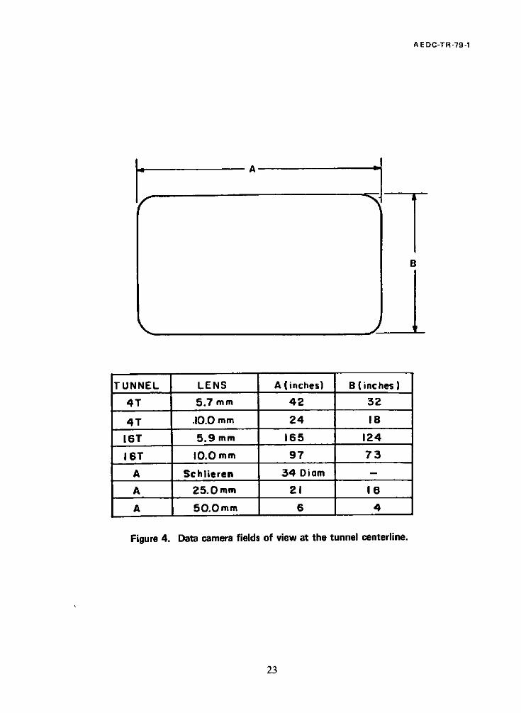
4. Data C a m e r a Fields of View at the Tunne l Center l ine . . . . . . . . . . . . . . . . . . . . . . . . . . . . 23
5. Sketch of Film Def in ing T iming Marks and Event Mark . . . . . . . . . . . . . . . . . . . . . . . . . 24
6. S tore Reference Points and Film Plane Def in i t ion ............................... 25
7. Examples of Release Mechanisms ..................................... .. . . . . . . 26
8. D r o p Model Ca l ib ra t ion Equ ipmen t .......................................... 29
TABLE
1. Typica l Tabu la t ed Data Ou tpu t Format s ....................................... 31
N O M E N C L A T U R E ....................................................... 33
3

A E DC-TR-79-1
1.0 INTRODUCTION
Dynamic drop, or "free-drop", store separation testing is a method of trajectory data acquisition whereby a scaled model of a store is released in the wind tunnel airflow and the subsequent path of the store is recorded photographically. In addition to being geometrically scaled, the models must be dynamically scaled to represent the mass and moment of inertia characteristics of the full-scale article. Free-drop testing is generally used when the item being tested is to be released from an internal bay, when the expected motion of the store would preclude captive trajectory testing because of sting/aircraft interference (such as an unstable store that would attain high pitch angles upon release), or when the physical size of the test article prohibits the installation of a balance (a rack, for example), or for final store separation verification prior to flight testing. Drop tests have also been conducted utilizing a constrained, pivotal release for fuel tanks and a lanyard-actuated deployment of "pop-out" fins.
The majority of free-drop tests at AEDC have been in the subsonic and transonic speed range and have been conducted in the Aerodynamic Wind Tunnel (4T). Several tests which required larger models than could be accommodated in 4"I" have been run in the Propulsion Wind Tunnel (16T), using the same techniques as those developed for 4T. Drop tests requiring Mach numbers greater than 2.0 have been run in the Supersonic Wind Tunnel (A). In each tunnel, data acquisition is by use of high-speed, 16-ram cameras. The final trajectory data are obtained by tracking the model trajectory on the film and processing this information with a digital computer which calculates the full-scale positions and angles as a function of time.
This report describes the techniques used in dynamic drop testing at AEDC and details the significant differences between those techniques as applied in the three wind tunnels.
2.0 TEST FACILITIES
2.1 PWT 4-FT TRANSONIC TUNNEL
2.1.1 Description
The Aerodynamic Wind Tunnel (4T) is a closed-loop, continuous flow, variable density tunnel in which the Mach number can be varied from 0. l to 1.3 and can be set at discrete Mach numbers of 1.6 and 2.0 by the use of fixed-contour nozzle inserts. At all Mach numbers, the stagnation pressure can be varied from 300 to 3,700 psfa. The test section is 4 ft square and 12.5 ft long with perforated, variable porosity (0.5- to 10-percent open) walls.
5

A E D C-T R -79-1
It is completely enclosed in a plenum chamber from which the air can be evacuated, allowing
part of the tunnel airflow to be removed through the perforated walls of the test section. A more complete description of the test facility may be found in Ref. 1.
2.1.2 Aircraft Support Method
For dynamic drop testing, the parent aircraft model is normally supported from the
ceiling of the wind tunnel using the base strut of the captive trajectory support (CTS) structure. The CTS strut can be moved vertically and axially in the wind tunnel to allow
optimum positioning of the aircraft model in the field of view of the test section data cameras. The aircraft model is mounted by either a sting or a strut which mates to a yoke
attached to the CTS strut. Discrete aircraft angles of attack can be set by manually rotating the aircraft support relative to the yoke. At present, it is not possible to vary the angle of attack with flow established in the tunnel. The existing support system positions the aircraft model at a yaw angle of 0 deg. If yaw angles other than 0 deg are desired, they can be
obtained by fabricating special adaptors to position the aircraft model at the desired angle.
If required by field-of-view consideration, the aircraft model can be offset laterally. An
adaptor to offset the model 8 in. is available. Other offset adaptors could be fabricated as
necessary.
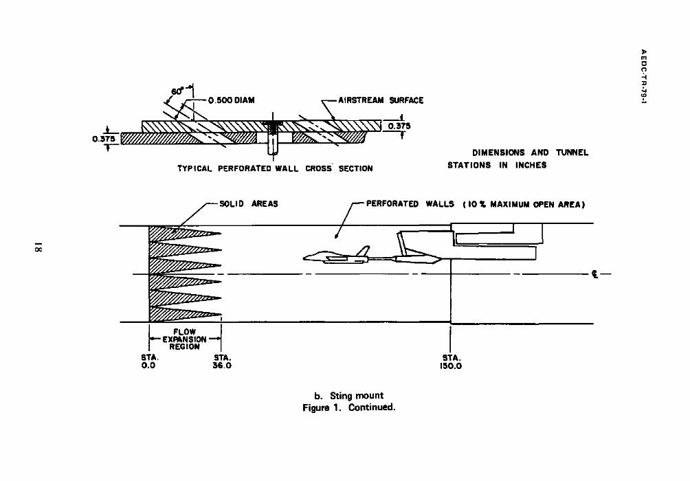
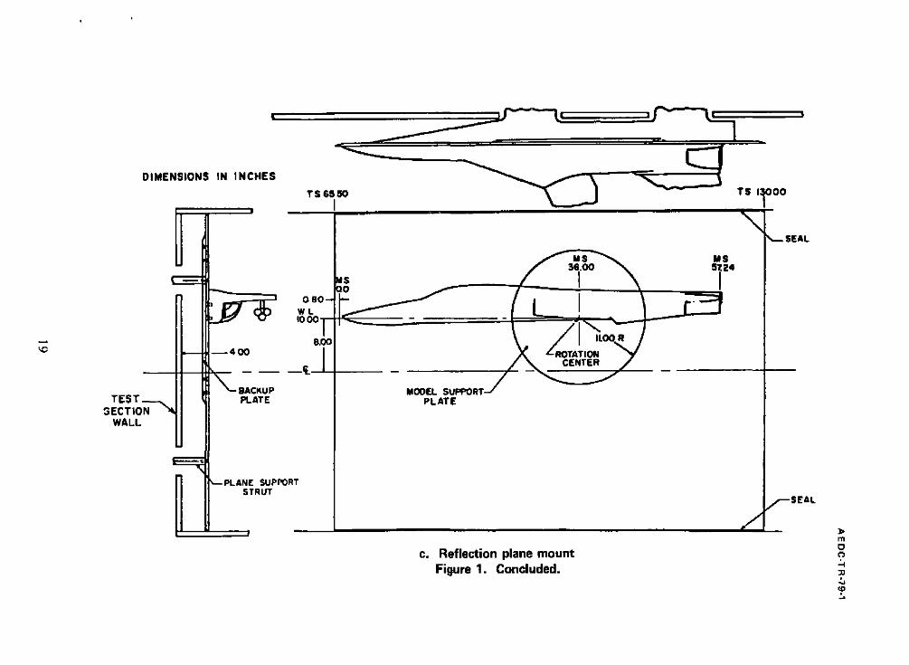
A sidewall-mounted reflection plane is also available if the use of half-span models is desired. Use of a half-span aircraft model allows larger scale models to be tested. Various installations are shown in Fig. 1.
2.1.3 Drop Model Recovery
Because of the expense associated with the construction of the dynamically scaled
models, a model recovery device is usually installed in the test section. The device consists of
two stainless steel, m½-in, mesh screens, one mounted horizontally near the floor of the test
section, and one mounted vertically at the entrance to the diffuser. Models will normally be
damaged even when they land in the screens; however, they can usually be salvaged and
reused with rework (the amount of refurbishment depends on the type of model and the method of construction). Use of the screens does not guarantee recovery of all models. Models which fly over the recovery screens are captured by screens located further down the
circuit, but these models generally are damaged beyond repair.
For tunnel operation above M= = !. I, the horizontal catching screen must be removed. Operation at M= = 1.6 and 2.0 requires that both horizontal and vertical screens
be removed.

AEDC-TR-79-1
2.2 PWT 16-FT TRANSONIC TUNNEL
2.2.1 Description
The Propulsion Wind Tunnel (16T) is a variable density, continuous flow tunnel capable
o f operation at Much numbers from 0.2 to 1.6 and stagnation pressures from 120 to 4,000
psfa. The maximum attainable Mach number can vary, depending upon the tunnel pressure
ratio requirements, with a particular test installation. The maximum stagnation pressure
attainable is a function of Mach number and electrical power. The tunnel stagnation
temperature can be varied from about 80 to 160°F depending upon the cooling water
temperature. The test section is 16 ft square by 40 ft long with perforated walls of six-percent
porosity. The test section can be removed and transported to a separate building for model
installation and removal. Two independent test sections, one of which has a permanently
mounted sting support system, are available. Additional information about the tunnel, its
capabilities, and operating characteristics is presented in Ref. !.
2.2.2 Aircraft Support Methods
Aircraft models used in previous dynamic drop tests in Tunnel 16T have been strut
mounted from the test section ceiling. However, the sting support system mentioned in
Section 2.2. I could be used if required (see Ref. 1). Both the vertical strut ceiling mount and
the sting support system have remote pitch capabilities. The angle-of-attack range available
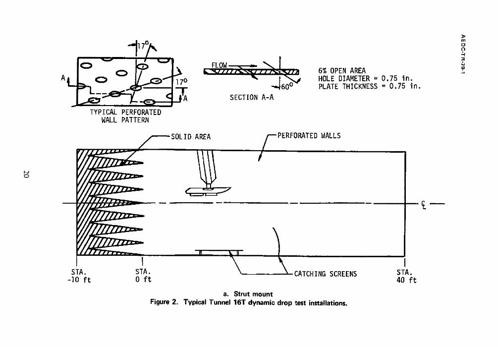
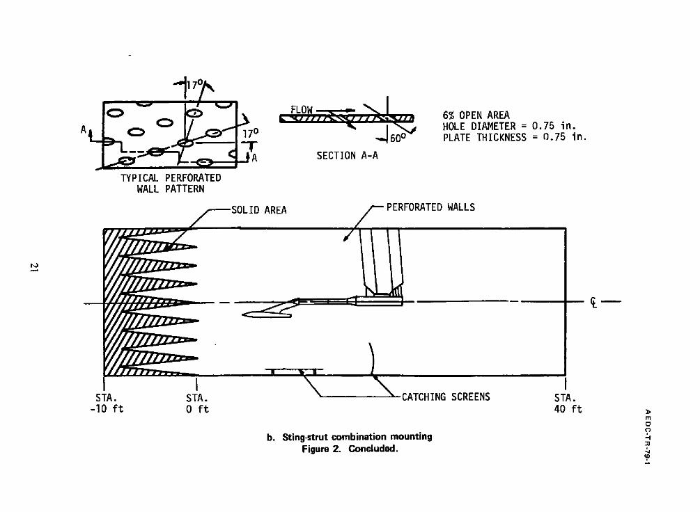
is dependent on the test installation. Two installations are shown in Fig. 2.
2.2.3 Drop Model Recovery
The model recovery system in Tunnel 161" consists of two stainless steel screens. A 4- by
8-ft screen is floor mounted on shock absorbers beneath the aircraft model. A vertical screen
is placed approximately 6 ft downstream of the horizontal screen to prevent the drop models
from being blown downstream into the diffuser. Models recovered from the catching screens
can generally be refurbished for reuse. The amount o f work required will depend on the type
o f model and the methods and materials used in its construction. Use of catching screens
does not guarantee 100-percent recovery of the drop models. Models which are not captured by the screens will probably be damaged beyond repair in the diffuser or by the compressor
protective grid.
Installation of the screens will reduce the maximum Mach number attainable to
approximately M~ = 1.4 and will increase power requirements by about 20 percent
(depending on test conditions).
7
A E D C -T R -79-1
2.3 VKF TUNNEL A
2.3.1 Description
The Supersonic Wind Tunnel (A) is a continuous flow, closed-circuit, variable density
wind tunnel with an automatically driven flexible-plate-type nozzle and a 40- by 40-in. test
section. The tunnel can be operated at Mach numbers from 1.5 to 6 at maximum stagnation pressures.from 29 to 200 psia, respectively, and a stagnation temperature up to 750°R at
Mach number6 . The minimum operating pressure ranges from about one-tenth to one-
twentieth of the maximum at each Mach number. The tunnel is equipped with a model injection system which allows removal of the model from the test section while the tunnel
remains in operation. A description of the tunnel and airflow calibration information may
be found in Ref. 2.
2.3.2 Aircraft Support Method
In-Ttinnel A, the aircraft model is mounted on a sting support mechanism in an
installation tank directly underneath the tunnel test section. The tank is separated from the tunnel by a pair of fairing doors and a safety door. When closed, the fairing doors, except for a slot for the pitch sector, cover the opening to the tank, and the safety door seals the
tunnel from the tank area. After the aircraft model and store are prepared for a drop, the personnel access door to the installation tank is closed, the tank is vented to the tunnel flow,
the safety, a.nd fairing doors are opened, and the model is injected into the airstream. After the drop is completed, the aircraft model is retracted into the tank and the sequence is reversed, with the tank being vented to atmosphere to allow access to the model in preparation for the next drop. The sequence is repeated for each drop. A tunnel installation
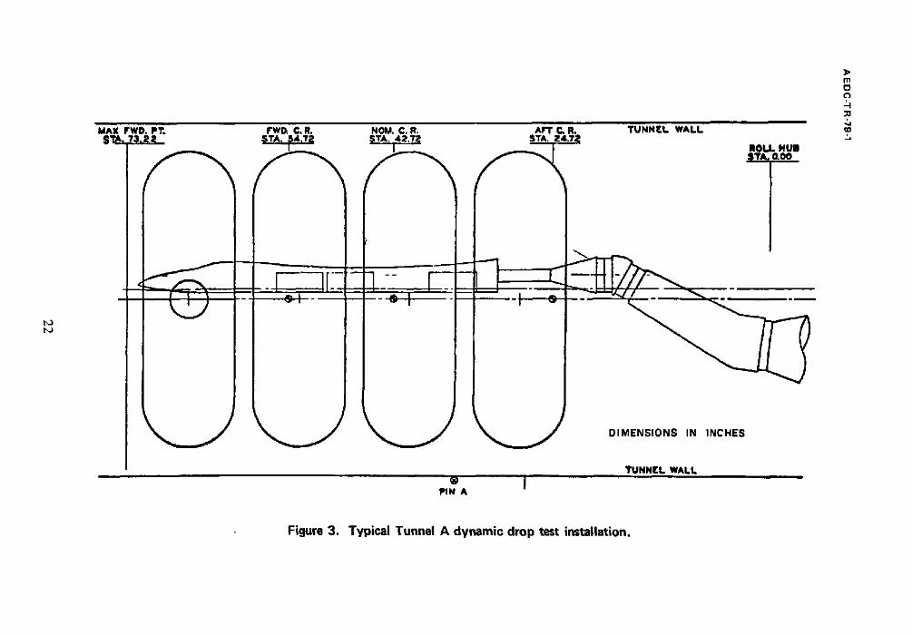
is shown in Fig. 3.
2.3.3 Drop Model Recovery
A model recovery screen can be installed in the installation tank below the opening for the safety and fairing doors. Some of the models fall to this screen, and others are swept
down the tunnel. In both cases, the models are usually damaged beyond repair by the impact.

AEDC-TR-79-1
3.0 DATA ACQUISITION
3.1 GENERAL
Primary data are acquired by means of 16-mm, high-speed motion picture cameras
mounted to give both side and bot tom views of the model in the test section. The actual
frame rates of the data cameras can be varied as required by the particular test program. The
data cameras are positioned in such a manner that the relative positions of their lines of sight
in the test section are accurately known. By using two orthogonally positioned camera.%
three-dimensional, six-degree-of-freedom trajectory data can be determined.
Two different methods are used to provide qualitative film data of a trajectory within a
short period of time after a drop has been made. These types of film data, called "quick-
look" data, are generally available within one to 15 minutes after a drop has been completed.
In Tunnel A, a Polaroid ~ camera with a rotating shutter is mounted outside the test
section. This camera gives a multiple-image photographic record o f the drop. Because
Tunnel 4T and Tunnel 161" test sections are enclosed in plenums which are at tunnel static
pressure, the use of a Polaroid camera is not feasible. Instead, an additional 16-mm, high-
speed motion picture camera, loaded with black and white film, is mounted so as to give the
desired view of the model. After a drop, the film is developed with a portable processor
located in the wind tunnel building.
Data acquisition is controlled by a sequencer which is programmed to automatically
actuate the test section lighting and cameras and to release the drop store at the proper time
intervals. To allow the time of store release and the camera frame rates to be accurately
determined, timing lines and an event mark signifying store release are optically placed on
the data film of all data cameras.
3.2 CAMERA INSTALLATION IN THE PWT 4T
In Tunnel 4T, the primary data cameras are installed at tunnel station 108.8 such that the
sight lines intersect orthogonally at, and with, the tunnel centerline. The cameras normally
are fitted with 5.7-mm lenses. However, 10-mm lenses are available if a larger film image
would be useful and the field-of-view requirements can be reduced. A listing of the field o f
view at the tunnel centerline for both the 5.7- and 10-mm lenses is shown in Fig. 4.
The quick-look camera is installed outside the tunnel side wall at station 97. It can be
fitted with various lenses as dictated by field-of-view and image size requirements. Frame
rates from 300 to 1,000 per second can be set.
A E DC-TR-79-1
3.3 CAMERA INSTALLATION IN THE PWT 16T
In Tunnel 16T, the primary data cameras are normally installed at tunnel station 9.4. If a
ceiling strut mount is used for the aircraft model, the cameras can be mounted at tunnel
station 20 although this position may be further downstream than is desirable. Various data
camera positions are available in Tunnel 16T, but with the available camera ports only one of
the two data cameras can be mounted so that its sight line falls on the tunnel centerline.
Regardless of their locations, the data cameras will be mounted so that the sight lines
intersect orthogonally. However, the position of the sight line intersection in the test section
will depend on the camera location that is chosen. Either 5.9- or 10-mm lenses are available
for the Tunnel 16T data cameras. The appropriate lens will be determined by specific test
requirements. A listing of the fields of view at the tunnel centerline is included in Fig. 4.
The quick-look camera can be located at several locations as indicated by field-of-view
requirements. Lenses ranging from 13 to 50 mm are available for this camera. Frame rates
from 300 to 1,000 per second can be set.
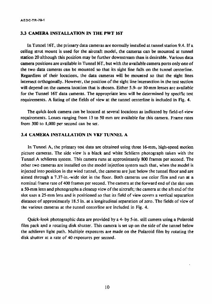
3.4 CAMERA INSTALLATION IN VKF TUNNEL A
In Tunnel A, the primary test data are obtained using three 16-mm, high-speed motion
picture cameras. The side view is a black and white Schliern photograph taken with the
Tunnel A schlieren system. This camera runs at approximately 800 frames per second. The
other two cameras are installed on the model injection system such that, when the model is
injected into position in the wind tunnel, the cameras are just below the tunnel floor and are
aimed through a 7.37-in.-wide slot in the floor. Both cameras use color film and run at a
nominal frame rate of 400 frames per second. The camera at the forward end of the slot uses
a 50-ram lens and photographs a closeup view of the aircraft; the camera at the aft end of the
slot uses a 25-ram lens and is positioned so that its field of view covers a vertical separation
distance of approximately 18.5 in. at a longitudinal separation of zero. The fields of view of
the various cameras at the tunnel centerline are included in Fig. 4.
Quick-look photographic data are provided by a 4- by 5-in. still camera using a Polaroid
film pack a.nd a rotating disk shutter. This camera is set up on the side of the tunnel below
the schlieren light path. Multiple exposures are made on the Polaroid film by rotating the
disk shutter at a rate of 40 exposures per second.
10

A E DC-T R -79-1
4.0 DATA REDUCTION
4.1 GENERAL
Model trajectory data are determined from the time-correlated, high-speed motion
picture film taken by the two primary data cameras. The data film is reduced by the use of a
film reader whereby each frame of the film is projected onto a screen. Positions of the store
reference points, relative to known points in the field of view, are measured along two
orthogonal axes by manually positioning horizontal and vertical crosshairs located on the
surface of the screen. Digital output from the film reader is input to a computer which
calculates the full-scale trajectory positions and attitudes.
4.2 DATA SYNCHRONIZATION
if accurate three-dimensional trajectories are to be obtained, the information acquired
from the side and bottom data cameras (which may be running at different speeds) must be
synchronized. This will insure that the dropped store occupies the same position in space
when data from the two cameras are correlated by the data reduction program. At AEDC,
this synchronization is accomplished in the data reduction program. The frame rate for each
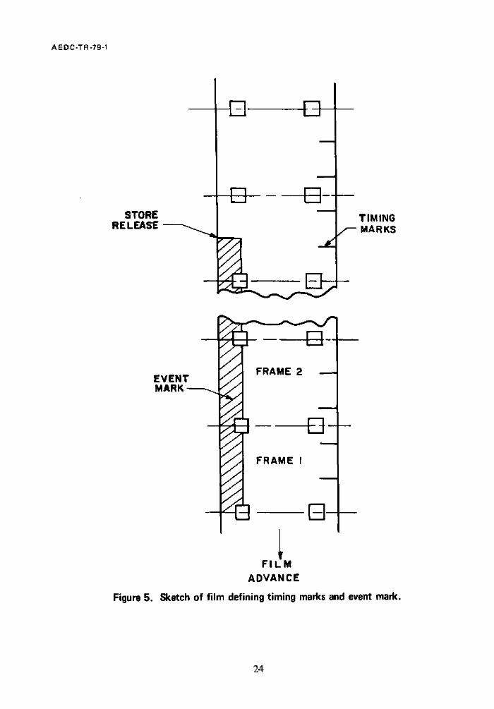
camera is determined from the timing marks recorded on one edge of the film (see Fig. 5).
The event mark which is recorded on the other edge of the film in each camera establishes a
time zero reference by identifying the frame of film on which store release occurs. The zero
reference and the frame rate are used to calculate the elapsed time since release for each
frame of data film for each camera. The side camera data are taken as the primary time
reference, and the bottom camera data are interpolated to obtain store positions at times
correpsonding to each frame of the side camera data.
4.3 DATA REDUCTION IN PWT TUNNELS 4T AND 16T
Calculation of the trajectories is accomplished by the simultaneous solution of the
equations which relate any point in the camera field o f view to the two orthogonal sight lines
of the data cameras. Location of the sight lines relative to a known point on the film (a
sprocket hole) and a scaling factor (called the apparent focal length) which relates the film
reader image to the full-size model in the tunnel are determined prior to the test by means of
a calibration using a grid board. The three-dimensional location of any point in the field of
view can then be determined using the method of similar triangles.
For complete six-degree-of-freedom trajectory data, the location of three reference
points on the drop store must be determined in each frame of film. These reference points
!
11

A EDC-TR-79-1
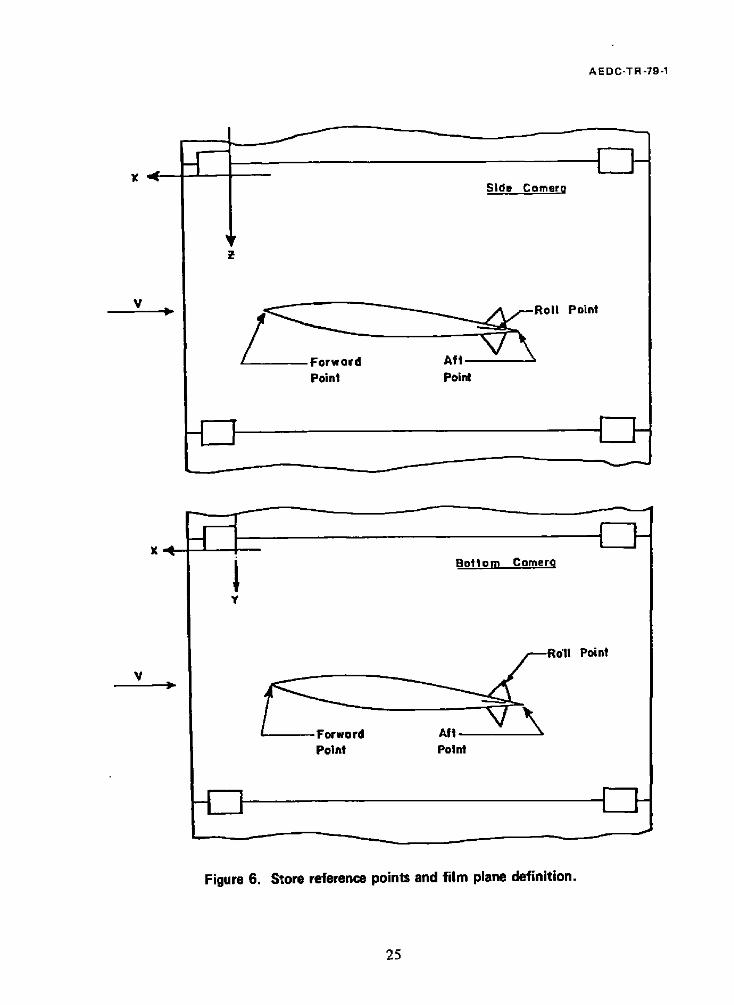
normally consist of one point at the store nose, one point at the tail, and a point laterally offset from the line joining the nose and tail reference points (see Fig. 6). The locations of these three points in conjunction with that of the store center of gravity relative to the nose reference point are used to define the angular and translational position of the store by
means of standard geometric relationships. The model-scale data are then converted to the equivalent full-scale values by means of the appropriate scaling factors.
4.4 VKF TUNNEL A DATA REDUCTION PROGRAM
Model trajectory parameters are obtained from the high-speed, time-correlated motion picture cameras located in the schlieren system and at the aft end of the slot in the tunnel
floor. To obtain the trajectory data from the film, grids are photographed by each camera. The schlieren camera uses a 6-in. grid which is attached to the tunnel windows and appears
on the data film. For the bottom data camera, a 2-in. grid is installed at a known location in
the tunnel and is photographed prior to testing. This grid is superimposed on the data film by the film reader during the data reduction process. The location of the store cg and the angle of the store relative to the grid lines are determined from the data film by the film reader. This information is then input to a digital computer which calculates the full-scale displacements and angles as a function of time.
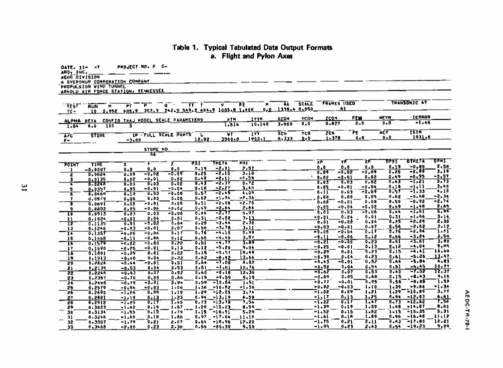
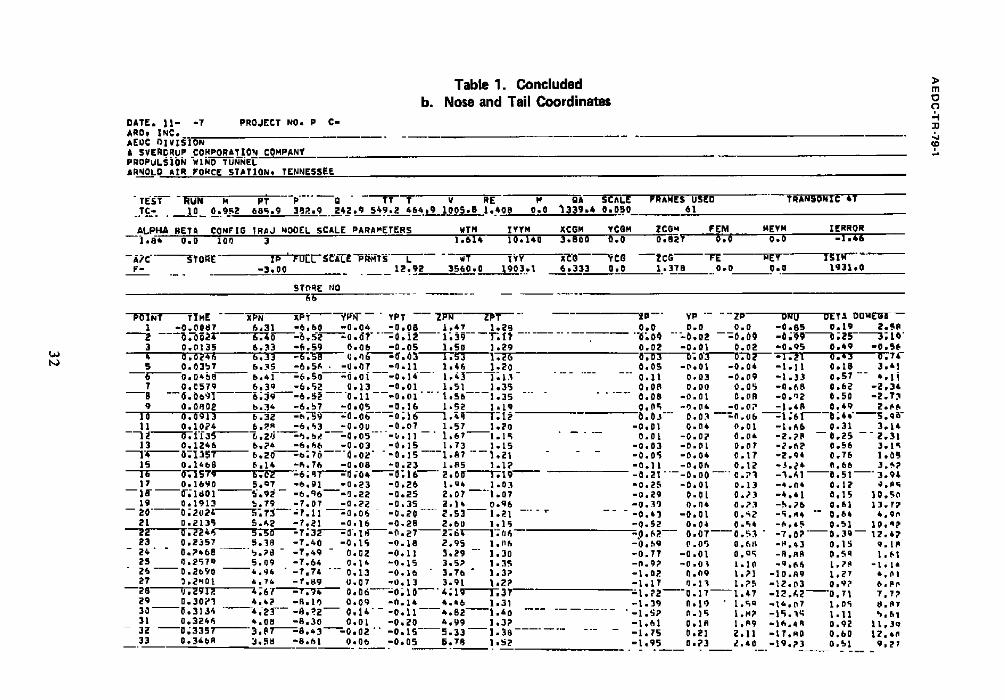
4.5 DATA OUTPUT
Standard data output consists of the full-scale translational and angular positions of the store with time in the flight- and pylon-axis systems. [Angular data can be presented in both
the Euler sequence (yaw, pitch, roll) and the pitch, yaw, roll sequence.] in addition, the nose and tail coordinates of the store are calculated as a function of time. Samples of the tabulator formats are presented in Table I. The parameters shown are identified in the Nomenclature. The above data can also be made available on magnetic tape and in plotted
form.
The time required for reducing trajectory data varies with the number of drops in a given test. However, unchecked data are generally available within two to three weeks. A print of the color data film is normally available within four days after each drop.
5.0 MODEL-SCALING METHODS
The three primary methods used in scaling dynamic drop store models are Froude
scaling, heavy scaling, and light scaling. A complete description of these scaling laws, including the applicable equations and the relative advantages and disadvantages of each, is included in Volume 1 of this series of reports (Ref. 3).
12
AEDC-TR-79-1
Although no one method of model scaling is necessarily the best method, the majority of
drop tests at AEDC have used the heavy scaling technique. Heavy scaling has given good
overall results in comparison with captive trajectory and flight test. data. However,
depending on the test objectives, Froude scaling or light scaling might be preferable, and suitable model design and data reduction can be provided for any of the scaling methods.
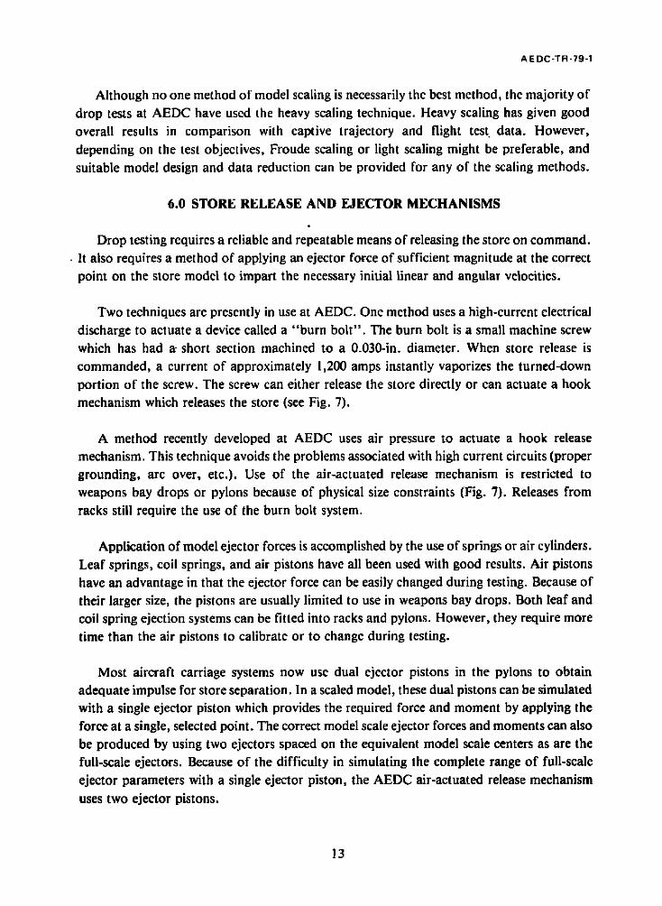
6.0 STORE RELEASE AND EJECTOR MECHANISMS
p
Drop testing requires a reliable and repeatable means of releasing the store on command. • It also requires a method of applying an ejector force of sufficient magnitude at the correct
point on the store model to impart the necessary initial linear and angular velocities.
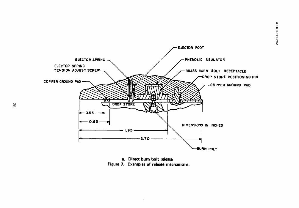
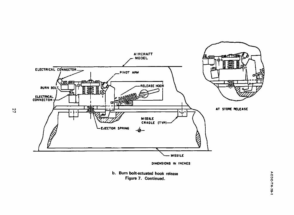
Two techniques are presently in use at AEDC. One method uses a high-current electrical
discharge to actuate a device called a "burn bolt". The burn bolt is a small machine screw
which has had a-short section machined to a 0.030-in. diameter. When store release is commanded, a current of approximately 1,200 amps instantly vaporizes the turned-down
portion of the screw. The screw can either release the store directly or can actuate a hook
mechanism which releases the store (see Fig. 7).
A method recently developed at AEDC uses air pressure to actuate a hook release
mechanism. This technique avoids the problems associated with high current circuits (proper grounding, arc over, etc.). Use of the air-actuated release mechanism is restricted to
weapons bay drops or pylons because of physical size constraints (Fig. 7). Releases from
racks still require the use of the burn bolt system.
Application of model ejector forces is accomplished by the use of springs or air cylinders.
Leaf springs, coil springs, and air pistons have all been used with good results. Air pistons have an advantage in that the ejector force can be easily changed during testing. Because of
their larger size, the pistons are usually limited to use in weapons bay drops. Both leaf and coil spring ejection systems can be fitted into racks and pylons. However, they require more
time than the air pistons to calibrate or to change during testing.
Most aircraft carriage systems now use dual ejector pistons in the pylons to obtain adequate impulse for store separation. In a scaled model, these dual pistons can be simulated with a single ejector piston which provides the required force and moment by applying the
force at a single, selected point. The correct model scale ejector forces and moments can also be produced by using two ejectors spaced on the equivalent model scale centers as are the
full-scale ejectors. Because of the difficulty in simulating the complete range of full-scale
ejector parameters with a single ejector piston, the AEDC air-actuated release mechanism
uses two ejector pistons.
13
AEDC-TR-79-1
Since the model scale ejector forces are determined by the same scaling laws used to
determine the model mass and inertia properties, it may be difficult to provide sufficient force with the model scale ejectors. Therefore, the ejection requirements should be considered during the initial stages of drop model design to assure proper simulation.
'7.0 DROP MODEL CHARACTERISTICS
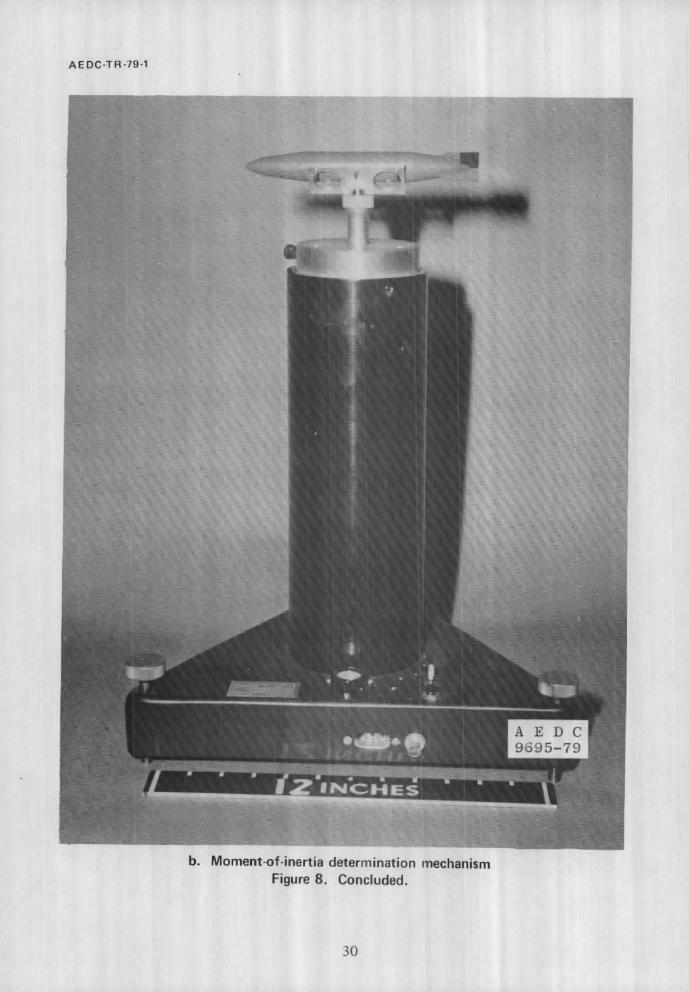
Although the desired model scale mass and moment-of-inertia properties are determined by the scaling laws used in their design, the actual model characteristics will vary somewhat
from this ideal because of precision limitations in the fabrication process and because of
design tradeoffs to limit model costs. For example, it has been found that allowing model center of gravity location to deviate by up to 3 percent of model length and moment of
inertia to vary by up to 6 percent from the ideal value will result in a significant reduction in
design time without adversly affecting the trajectory motion. However, it is necessary that the actual model characteristics be measured prior to testing to provide a means for proper
evaluation of the test data and to determine the accuracy of the simulation.
Model center of gravity location relative to some easily defined position must be determined in the XB, YB, and ZB planes. Store moment of inertia about the actual center of gravity should also be measured. Model mass and inertia properties should be determined after the models have been painted and any desired markings placed on the store. Models are generally painted to enhance their visibility on film. Experience has shown that a nonglossy yellow model with a light blue or gray background gives the best contrast. The AEDC has
the necessary equipment to determine the center of gravity and the inertia properties of drop models. Photographs of this equipment are presented in Fig. 8.
Model ejector calibrations are required to determine the necessary springs or air pressure
and the point(s) of application of the ejector which give the desired initial vertical and
angular velocities to the store. Calibrations are generally made using a time/distance correlation to determine the velocity imparted by the ejectors. Several methods for obtaining the necessary information exist. Both motion picture film of the release and a photo diode
array which gives a time history of the drop have been used. A stroboscopic technique presently is being used at AEDC which gives a multiple image on Polaroid film. The
necessary measurements are made directly from the film. The angular and linear velocities imparted by a given ejector can be determined quickly after the drop. Any necessary
adjustments to the ejector(s) can then be made and new measurements taken within a very short period of time.
14
A EDC-TR-79-1
8.0 INFORMATION REQUIRED FOR CONDUCTING DYNAMIC DROP TESTING AT AEDC
The following information is needed for each store prior to test entry.
Full-Scale Parameters
!. Store weight, lb 2. Store moments of inertia about the body axes, slug-ft 2 3. Store center-of-gravity location, ft 4. Store forward lug location, ft 5. Ejector force (for each piston if more than one), lb 6. Store linear and angular ejection velocities, ft/sec and deg/sec 7. Ejector stroke length, in. (for each piston)
Model-Scale Parameters
i. Store weight, lb 2. Store moments of inertia, lb-in. 2 3. Store center-of-gravity location, in. 4. Store attachment point location, in. 5. Store dimensions, in. 6. Store linear and angular ejection velocities, ft/sec and deg/sec 7. Ejector stroke length, in. (for each piston)
Test Parameters
I. Mach number 2. Release altitude 3. Tunnel dynamic pressure
Other items of information needed prior to testing are:
I. Scale factor 2. Scaling law(s) used 3. Desired data output 4. Type of ejector used 5. Any unusual hardware or
balance, etc.)
test requirements (e.g., pivot releases, installed
15
AE DC-TR-79-1
As mentioned in the previous section, the AEDC has the capability to measure the necessary model mass and inertia properties. Model design and selection of test parameters to simulate specific flight conditions can also be accomplished.
9.0 SUMMARY
Dynamic drop testing provides a very valuable tool in the determination of store separation characteristics and for final verification of the store trajectory prior to flight testing. It is especially useful for weapons bay releases, for releases in which the store model motion and/or mounting requirements would result in interference between the store model or its mount and the aircraft model, and for configurations in which balance mounting is impractical.
The AEDC continuous flow, closed-circuit wind tunnels provide a testing capability at Mach numbers from 0.2 to 6.0 over a wide range of simulated altitudes, in addition, the availability of the 16-ft-square transonic test section gives great latitude in the choice of model scale when testing is conducted in the subsonic and transonic ranges.
The AEDC has the capability to plan and conduct a complete drop test program. The expertise of AEDC personnel in dynamic drop testing includes model design, construction, and calibration as well as testing, data reduction, and data analysis.
REFERENCES
1. Test Facilities Handbook (Eleventh Edition). "Propulsion Wind Tunnel Facility, Vol. 4." Arnold Engineering Development Center, June 1979.
2. Test Facilities Handbook (Eleventh Edition). "yon K~,rm~n Gas Dynamics Facility, Vol. 3." Arnold Engineering Development Center, June 1979.
3. Carman, Jack B. "Store Separation Testing Techniques at the Arnold Engineering Development Center, Volume h An Overview." AEDC-TR-79-1, to be published.
16

, ~ ? ~ / - - 0.500 DIA. ~---AIRSTREAM SURFACE
TYPICAL PERFORATED WALL CROSS SECTION TUNNEL STATIONS AND DIMENSIONS ARE IN INCHES
- .a
~_ FLOW "~4 EXPANSION REGION
STA. STA. 0.0 36.0
D AREAS PERFORATED WALLS
I
STA. 150.O
(IO % MAXIMUM OPEN AREA)
' I I
a. Strut mount Figure 1. Typical Tunnel 4T dynamic drop test installations.
m o c~
-11 :a (D
0.5oo DIA. ~--A,RSTREAM S, RFACE " , ( ~ J"~ / -- ~ - ___t
o.~: 5 ~//////////////////~,:. : . ~ r~ r / /~ ' . ~.'~///~ ,
TYPICAL PERFORATED WALL CROSS SECTION
DIMENSIONS AND TUNNEL STATIONS IN INCHES
m 0
"n
~D
DO
AREAS /-
~._ FLOW ._~ EXPANSION
REGION STA. STA. 0.0 36.0
PERFORATED WALLS ( I0 Y. MAXIMUM OPEN AREA)
I I 1
STA. 150.0
~ m
b. Sting mount Figure 1. Continued.
,, I I t l I J I ~ l I
DIMENSIONS IN INCHES TS 6550
~ 4 0 0
T E S T ~ II ul PLATE SECTION ~ 1
W A L L ~
!
~ PLANE SUPPORT STRUT
i
WOL.B 0
I000
'T MOOEL SUPPC
PLATE
C. Reflection plane mount Figure 1. Concluded.
TS I ~000
\ SEAL
MS 5i24
/--SEAL , /
m o
¢D
A
TYPICAL PERFORATED WALL PATTERN
SECTION A-A
6% OPEN AREA HOLE DIAMETER = 0.75 in. PLATE THICKNESS : 0.75 in.
AREA r " PERFORATED WALLS
7> m
C)
"n
{D
l . J 0
m
STA. - I0 f t
I STA. 0 f t
Figure 2.
CATCHING SCREENS
a. Strut mount Typical Tunnel 16T dynamic drop test installations.
I STA. 4O f t
t~J
A
SECTION A-A
6% OPEN AREA HOLE DIAMETER = 0.75 in. PLATE THICKNESS = 0.75 in.
TYPICAL PERFORATED WALL PATTERN
fSOLIOAREA FPER ORATEOWALLS # # l a m r ' "
STA. STA. -lO f t 0 f t
STA. 40 f t
b. Sting~trut combination mounting Figure 2. Concluded.
~>
m
C)
-n
t~ I'.J
MAX FWD. P ~ FwI~ C.R. NOM, C, R. ~TA. 42.72
U-
AF'I" C. 1t." ' STA. 24.72
® I PIN A
TUNNEL WALL
D I M E N S I O N S IN
TUNNEL WALL
INC HES
ROLl. HUB l'rA, ¢~oo
m
~0
£o
Figure 3. Typical Tunnel A dynamic drop test installation.
A E DC-TR -79-1
-¢
f
A
J
1 B
T U N N E L
4 T
4 T
16T
16T
A
A
A
Figure 4.
LENS
5 . 7 m m
• 10.0 mm
A ( inches)
4 2
2 4
B ( inches )
3 2
18
5 . 9 r a m 165 124
I 0 . 0 mm 9 7 7 3
S c h l i e r e ~ 3 4 Diam --
2 5 . 0 mm 21 I 8
5 0 . O m m 6 4
Data camera fields of view at the tunnel centerline.
23
A EDC-TR-79-1
STORE RELEASE
EVENT MARK
-El
N
~,, - r-l-~-__ TIMING
~ ,. ,.~.. ~ ~. MARKS
/ /
J f
//~////-I FRAME 2 - -
¢x~J . f j ,
~ f FRAME I
~ m
Figure 5.
FILM ADVANCE
Sketch of film defining timing marks and event mark.
24
AE DC-TR-79-1
X -~
V
E~- Side Comerg
~ R o II Point
Point Point
-IZI
V
x ~ -4--1
|
1 Y
Botlom Comera.
~ Ro'II
Point Point
Point
- ] -L_
Figure 6. ~ore reference points and film plane definition.
25
FOOT
m C~ C)
~o
tD
EJECTOR
EJECTOR SPRING TENSION ADJUST S(
COP PER GROUND PAD
LIC INSULATOR
BRASS BURN BOLT RECEPTACLE
F ~ STORE POSITIONING PIN
COPPER GROUND PAD
~ J
Q-- 0.55
e----- 0.6 5 - - ~
DROP STORE
1.95
2.70
DIMENSIONI
a. Direct burn bol t release
Figure 7. Examples of release mechanisms.
IN INCHES
BURN BOLT
t,J ,.,.1
ELECTRICAL
BURN BO
ELECTRICAL CONNECTOR -.~
AIRCRAFT f MODEL
PIVOT ARM
HOOK
MI SS ILE CRADLE
EJECTOR SPRING . . ~
( T Y P )
MISSILE
DIMENSIONS IN INCHES
b. Burn bolt-actuated hook release Figure 7. Continued.
AT STO~ I~LEAS(
]> i1"1 o (-~
:4 (D

I,,a O0
B: A S
R E LEASE ACTUATION PISTON "-'~
EVENT SWlTCt'l'--~ \ FORWARD EJECTOR SPRING--'-~ ~
FWD EJECTOR PISTON--~---/I / / I STORE RELEASE
HOOK F'RE~V " " I ~ - ~ J . . . . I.O0 - - - -
REF
I AFT EJECTOR (/ PISTON
-- HIGH PRESSURE AIR SUPPLY
\ ~- RATCHET (TYP) ~ - - A F T EJECTOR PISTON
DIMENSIONS IN INCHES
l> m
:0 ¢O
c. Air-actuated hook release Figure 7. Concluded.

t~J
a. Center-of-gravity determination mechanism Figure 8. Drop model calibration equipment.
A E D C 9 6 9 6 - 7 9
~> m
C)
~0
¢D
AE DC-TR-79-1
A E DC 9695-79
i~ii~! :'~!!ii!i~i'~i~'!il, '̧̧ ~ ~ii~, % ~i!, ~, . . . . . . . ,~
~ :i ~, :ii: I ii ~: /~ ~i ~
b. Moment-of-inertia determination mechanism Figure 8. Concluded.
30
DATE, 11- -7 PROJECT NO, P C- AB0~_INC, AEOC UIVISION A SVE~O~U?_Cg~PJ_R.AT.__.I0 N COMPANY
"PROPULSION ~IND TUNNEL ABNOLU A~R FOHCE STAT~QN, TENNESSEE
Table 1. Typical Tabulated Data Output Formats a. Flight and Pylon Axes
TEST RUN M TO- __ 1_..._0 0.952
PT P " ' - -Q" " TT T V R( 6+~S.93~?.~ 242,9__5A_.9_,2~46~_,9 |.Q..Q_5_,8 t . A 0 ~
ALPHA. BETA CONFIG TRAJ MOOEL SCALE PARAHETER__S 1,8~ 0.0 100
AIC STORE IP .FULL SCALE PRMTS L F- -3 ,00 12092
STORE NO
H OA SCALE o , 9 ~ 9 _ . ~ o ~o5o . . . . .
66
WTH ~yyM XCGM 1,~14 10,140 3.800
~T IyY xcu 3560,0 1 7 0 3 , 1 _ . . ~ 6 ~ 3 3 _ _ 3
"-POINT TIME X Y Z PSI ~HET-'~--P-'HI 1 -0,0007 0.0 0.0 0.0 0 . 1 9 -2,0~ ?,57
o , 0 o ~ 0.09 -0 ,02 -0 .09 0,25 -2 .15 3.18 3 0,0135 0002 -0,01 0.02 0,~9 -2,11 -n,S~ 4 0.024~ 0,03 0,03 0,02 ~ 3 -2 ,37 0.72 S 0,0367 0,05 -0~OI -0 ,04 0~18 -2 .27 3,4n 6 0 ,046q 0 .12 0 .03 - 0 . 0 8 0 ,57 - 2 , 4 9 ~,Oq 7 0.0519 0,08 0,00 0.06 0,62 -1 ,84 -P.36 8 0.0691 0.08 -0,01 0 , 0 8 0,51 -2 ,08 -2 ,75 9 0.0802 O.OS -0 .04 -0 ,0~ 0,49 -2 .64 ~,64
10 0,0913 0.03 0.03 -'0.06 0.4~ -2 ,77 5.97 11 0.1024 - O , O l 0.04 O.Ol o . 3 1 -2 .82 3 . 1 3 1--2--"" 0,1135 0,01 -0 .02 0 . 0 4 0 . 2 5 -3 ,44 2,30 13 0.12~6 -0 .03 -0,01 0.07 0 . 5 6 -3 .78 3 .1 ]
- 0 . 0 4 O , IT 0 . 7 6 - A . I O 0 , 9 9 - - ~ - - - - - - ' ~ ; i 3 5 ~ -o .o6 IS O~&b8 -0.11 -0 ,06 16 0,1b79 - 0 , 2 2 -0 ,00 17 0,1690 -0 ,25 -0.01 18 0.1801 -0 .79 O,Ol
0,12 0,66 -4 .40 3,$7 0.22 0,51 °#,77 3.89 0,13 0,12 -5 .20 9.64 0.22 0.15 -5 ,~7 10,~9
FRAMES tISED 6|
TRANSONIC AT
YCGN ZCGq FEM NEYH .IEBROR 0,0 0,827 0.0 0,0 - | , 4 6
YCG ZCG FE NEY IStM 0,0 1.378 0,0 0,0 193100
XP yP"--2P--"-'~P.~-l-----b-f'~(TA OPHI o.o o .o o ,o o, 9 _ _ ~ 9 ~ B s _ _ _ 2 ~ L 0.09 " - 0 .02 -0 .09 O.~S 09.99 3,19 0.02 -0 ,01 0,02 O,A9 -0095 -O,SY 0.o3 o,o3 0,02 00A3 L~,21 0,73 O.OS -0,01 -O,OA 0.18 - 1 ~ 1 1 3 ~
- - 0 . 1 1 0,03 - o . b ~ - - o ; ~ 7 -1 ,33 A . I n 0,08 0,00 0 . 0 9 _ 0 . 6 2 -0 ,68 - 2 , 3 A
- b , o ~ - - - O . O l - - o . o 8 o . 5 o -o ,92 - ~ 0 ~ 0,0S -0 .04 -0 ,02 0,49 -1 ,48 2,69 0.03 0,03 -0 ,06 0,AA -1,61 509n
o O , O I O . O A 0.01 0031 - !~66 3 , I t O.Ol -o ,0~ - o.o4 0,~5 - 2 . 2 8 2030
-0 ,03 *0,01 0.07 0.56 -2 ,62 3,12 - o . o s -o ,o~ o.17 0,76 1219~- - - -~0~1- -0,11 -0 ,06 0,12 -0 ,21 -0 ,00 0,23 -0 ,25 -0 .01 0,13 -0 .29 0,01 0.23
0,66 -3 ,26 3.Sq 0o51 - 3 , 6 1 3,90 0012 -4 .0A 90~q 0,1s " ~ 1 4 ~ - - ' - " 1 6 1 ~ 9
19 0~1913 -00~0 20 0.202A -0 ,44 21 0,213~ -0 ,53 22 0,2266 -0 ,63 23 0,~357 -0.T0
--~;---------~.~Aa8 -o.79- 25 0 ,2529 - 0 , 9 4 26 61~Q0 -1,0+ 27 0 . 2 8 0 1 - 1 ~ 9 28 002912 -1 .25
._. 2 9 0.3023_1_._-1,42 . . . . 0 , 1 9 1 , 5 7 . _ _ 30 0 . 3 1 3 A -1 ,55
0.04 0,~2 0.62 -6 .42 13,§6 "0.01 0,51 0,6A -7 ,00 A,82
0.04 0~53 O.SI -7 ,61 10,76 0,07 0,52 0,40 ; 8 ~ f ~ 12,36 0,05 0.66 0,15 -9059 9,15
-0.01 0 , 9 4 - - 0059 -10.0~- - 1051 -0003 1.08 1030.__-10.~2 -1 ,3~
o . o q 1,19 1 . 2 9 -12.05 3,74 0,13 1.23 0.94 -13,19 6,59 0,17 1.65 0.73 -13,78 7,5~
1 , 0 9 _ - 1 5 . 2 3 8 . 5 ~ . _ _ 0,15 1.79 1.15 -16,51 5.29
-0 .39 0,04 0,23 0061 -5 .26 13,67 -0 ,~3 - 0 , 0 1 - - " O,SP 0,66 -5 ,84 4,03 -0 ,52 O,OA 0.SA 0,51 -6 ,45 10,72 -0 ,62 0,07 0.53 0cA0 -7 ,02 12037 - 0 , 6 9 O.OS 0.68 O, IS -8 ,43 9,16 -6.77 -o.01 o.95 o.s~--'~e.e8 z . s~ - 0 0 9 2 - 0 , 0 3 1 , 1 0 1 , 3 0 0 9 0 6 6 - l , 3 m - 1 o 0 2 - - 0 . 0 9 - - - 1 , 2 1 | ~29 - -~10009 3077 -1 ,17 0,13 1,25 009t -12003 6,_61__ - ! , 2 2 0,17 1.47 0,73 -12062 r ,S6 -1 ,39 0,19 1.59 1,n8 ol&,O7 8061 ; 1 , 5 2 - - 0 0 1 5 - - 1 0 8 2 - - " "1015"-~15035 5031
1,89 0o96 -16068 !1 ,12 2 , 1 1 0 ,63- - ;17080 - - -12,21 2.40 O.SA -19023 q~oq_
31 _ _ 0 . 3 ~ 4 6 -1o65 0,18 . . . . . 1.86..__ 0,97 32 0,3357 -1 ,79 0,21 2,07 0,64 33 0,3468 -2,00 0,23 2.36 0.54
- - 1 7 . 6 ~ 1101~ - IR .96 1 ~ , 2 0 - 2 0 , 3 9 9,OB
- 1 , 6 1 O . IR - ! , 7 5 0,21 "1 .99 0,23
3> m C3 0
-n
DATE. I I - -7 PROJECT NO. P C- AROt INC. AEUC DIVISION A SVERCRuP COHPORATION COMPANY
Tab le 1 Conc luded
b. Nose and Ta i l Coord ina tes
3> m O
"rl
(D
PROPULS]bN MIN0 TUNNEL ARq_~ObD. AI ~ FOHCE STATION, TENNESSEE
L ~ i,,.I
" T [ S T - - - RUN . PT .TC~ | 0 0.952 68q.9
ALPHA RETA CONFIG IRaJ MODEL sCALE PARAMETERS - - i . ~ o.o zoo 3
- ~ C . . . . ~?oHE F- - 3 . 0 0
P . . . . . O TT T V RE H OA SCALE 3 ~ . 9 ~42.9 549,Z ~64,9 1005.6 1.600 0.0 ~339 .4 0,050
WTM IYYM XCGM YCOM - - 1 . 6 1 4 10.140 3.800 0 .0
1 ~Y- - - - - x~o - - - -VCG 12,92 3560,0 1903.1 6 ,333 0 .0
Im'FUL~-SC~"LE-P~',t~S L ~T
STORE rJO 66
- - - X - P T ~ - - ~ N - - YPT . . . . ~PN ZPT - 6 , 6 0 - 0 . 0 4 - 0 . 0 8 1 . 4 7 1.29 ~ , ~ 2 - - ' - - ' : o . ~ ? . . . . ; 0 . i 2 - - 1 1 ~ § . . . . . F ; l ? - 6 . 5 9 0 .06 - 0 . 0 5 1.50 1.29 -61~8-- - o , o 6 = ~ . 0 3 - " " T ; . ~ - ' - - 1 ~ z o - 6 . 5 6 - 0 . 0 7 - 0 . I I 1 , 4 6 1 . 2 0 1 6 . S O - - - ~ . 0 ~ - - ' - - 0 . 1 4 l . ~ J 1.13 - 6 . 5 2 0 .13 -0 .01 1.51 1.35
~ N ~ X H [ - - -xXls~ I - 0 . 0 0 8 7 6.31
- - ~ . . . . ~7o~2~ 6 . ~ o 3 0.0135 6 .33
0 , 0 ~ 4 ~ 6.33 S 0.0357 6 .35 6-- 0 . 0 ~ 0 6.41 T 0,0579 6 .3~
- - 8 - ~ . 0 6 9 1 6 1 3 9 - - - 6 . 5 2 . . . . 0 . 1 1 - - - 0 . 0 1 . . . . 1.56 . . . . . 1.35 " 9 0 .0~0~ 6,3~ - 6 , b T - 0 . 0 5 - 0 . 1 6 1.52 1,19
1o o . o v z 3 6 . 3 2 ~ 6 1 5 ¢ - ' - ~ 0 . o ~ - = o ; 1 ~ - ~ . ~ ' - T ; 1 2 I I 0 . 1 0 7 ~ 6 . ~ - 6 . ~ 3 -O.0u - 0 , 0 7 1.57 1 . ? 0
- ' - ~ 2 - - ' ~ - ~ , | [ 3 ~ 6 , 2 U - ~ , b ~ - - - - - O , O S . . . . - 5 , 1 1 - - 1 , 6 7 1 , 1 ~ 13 0.1246 6 , 2 ~ - 6 . 6 6 - 0 . 0 3 - 0 .1S 1,73 1.15
--l'~--0735?--------6.2d---"~u;?6---0.0~" " 0 . 1 5 . . . . 1.~7 "- -- 1.21 15 0.1466 6 .1~ - 6 , 7 6 - 0 . 0 8 - 0 , 2 3 I ,R5 1 . 1 P io O"~S?~ 6.0~ ~61~7"'--~010~'-'--~0116--2.00"'-'-I~19 - - 17 0,1690 5 , o 7 - 6 , 9 1 - 0 , 2 3 - 0 , 2 6 l . q& 1 . 0 3
- - 1 ~ - - 0 " ; I d 0 1 - - ~ . 9 2 - " - 6 . q 6 - - - 0 . ~ 2 - 0 . 2 5 2 . 0 7 - - " | . 0 7 19 0.1917 b , 7 9 - ? . 0 7 - 0 . ~ 2 - 0 . 3 5 2.14 0,96
--20----0;2u2~----~.;7~--~?.II--;0,06 - - 0 . 2 0 - - - 2 . 5 3 - - - - ' 1 , 2 1 21
- - 2 2 - - 23
- 24 75
27 - - 2 8 - - - - ' -
29 3 0 - - 31
0 . 2 1 3 S 5 . ~ 2 - ? , 2 1 - 0 , 1 6 - 0 . 2 8 2 , 6 0 1 , 1 5 ~ - . ~ . 4 ~ - 5 U - - - . 7 1 3 2 - ~ 0 . 1 ~ - - . 0 , ~ 7 - - 2 1 6 ~ - - - - 1 ; 0 6 0.2357 S.~8 - 7 . 4 0 - 0 . 1 5 - 0 . 1 8 7 .95 1 . , 6 0 , P ~ 6 8 . . . . b . 7 8 " - 7 , 4 9 0.02 - 0 , I I 3,~9 " 1,3o 0.257O 5.09 - 7 . 6 4 0 , I ~ - 0 . 1 5 3.5P ] . 3 5 0.~090 - - 4 . 9 ~ " - 7 .74 " ' - 0 .13 - 0 . 1 6 3.76 - 1.3P 2,2~01 ~ , ? ~ - t , ~ 9 U . 0 7 - 0 , 1 3 3 . 9 1 1.2P Q ; ~ q ~ ; 6 T - - - ~ 7 , - ~ - 0 .06 - - ' -~0110 - " & ; l ~ 3 7 0.30~3 4.4~ -R ,1o o ,09 - O . l A 4 .46 1.31
0.3~4~ ~.08 - 8 , 3 0 0.01 - 0 , ~ 0 4 .99 1.37
FRAMES USED 61
TRANSONIC AT
ZCOM FEM MEYM o.0~? o;~ 0 . 0
- - 2 C G - - - F [ .EY 1.376 0 .0 0 .0
IERROR - l . & 6
l S I m 1 9 3 1 . 0
~ P - " YP . . . . . . Z~ 0 .0 0.0 0 .0
~ ; o 4 - ; 0 , 0 2 - - ; 0 , 0 9 0.02 - 0 . 0 1 0,02 - 0 . 9 5
0.0S - 0 , 0 1 - 0 . 0 ~ - 1 . 1 1 0.11 0.03 - 0 . 0 9 - 1 . 3 3 0 , 0 8 0 , 0 0 0 , 0 ~ - 0 . 6 8
. . . . . . . 0 , 0 8 - 0 , 0 1 O,oA - 0 , ~ 2 0 , 0 q - 0 . 0 ~ - 0 . 0 ~ - I , 4 8
- - ~ . 0 3 " - " 0 . 0 3 - - - ; 0 . 0 6 - - 1 ; 6 ~ - - - - - 0 . 0 1 0 . 0 ~ P .OI - 1 . A 6
0 . 0 1 - 0 , 0 ~ 0 . 0 4 - 2 . 7 0 - 0 , 0 3 - 0 , 0 1 O,O? - 2 , ~ ?
- - O . O q - 0 . 0 4 0 . 1 7 - 2 . 9 ~ - 0 .11 - 0 . 0 6 0.12 - J , ? s
UNU O [ T l O O V ~ G [ - - - 0 . 8 S 0.19 2.SP - 0 ~ q ~ 1 2 5 - - - - - ' 3 ; 1 0
0 .49 - 0 . $ 6 0 . ' 3 o . T ~ 0.18 3.61 0 . 5 7 " ' - ~ . 1 | 0.62 - 2 . 3 4 0.S0 - 2 . 7 ~ 0 .4q 2 . 6 ~ 0 1 4 ~ - - 5 . 9 6 - 0 . 3 1 3 . 1 6
- ' 0 . 2 S - 2.31 0.56 3 .1~ 0.76 1.0S 0 , 6 6 3.~P
32 --0~33s'r--'--3,~7----;0.43----0.02-0.15---5.33--1.36 . . . . . . . . . . . . . . - 1 . 7 S 33 0 . 3 4 6 A 3 .~U - 0 . 6 1 0 . 0 6 - 0 . 0 5 5 . 7 0 I . S ~ - 1 . 9 5
- 0 , ~ " - - 0 . 0 0 . . . . . 0 . ~ - 0 . 2 5 -0 .01 0.13 - 0 . 2 9 0.01 0.73 - 0 . 3 7 0.04 0.73
. . . . - 0 . 4 3 - 0 . 0 1 0.~2 - 0 . 5 2 0.04 0.~4 - ~ . ~ 2 . . . . 0 . 0 7 - - - - 0 . 5 3 - 0 . ~ 9 0.0~ 0,6~! - O . t ? - 0 .01 0.Q~ -0 .9P - 0 . 0 1 1 . 1 0 - 1 , 0 ~ 0 , 0 9 I , ~ I - I , 1 7 0 , 1 1 1 , 7 5 - I , 7 2 - - - - 0 , 1 7 - - I , 4 7 - ! . 3 9 0 .10 " l.~O
" - I . S P 0.1q l . ~ P - I . 6 1 0 , 1 8 1 . ~ 9
0 . 2 1 2 . 1 1 0.73 ~.40
- ~ . A I - - O . S I - - ' 3 . g & -4 .N6 0.1~ 4 ,~q -4 .41 0.15 IO.SO -S ,?S 0.61 13.?? -S .~4 "- 0,66 4 ,q0 - 6 . 4 5 0.51 10,~?
• - 7 , 0 P ' - - - 0 . 3 9 - - 12.67 - ta.43 0.15 Q.IR -~ .AA 0.sq 1.61 -Q.5~ | . ? p -1.1.
- 1 o . a 9 1.2T 4.01 - t Z . 0 3 0.9? 6 .0o - 1 2 . ~ 2 - - ' 0 , 7 1 7 .7? -1& ,07 1,0S 8 .87 - 1 ~ . ~ ! . 1 1 ~ . ~ ! - l f l . ~ R O.9Z 11.39 - l T . ~ O 0.60 12.4n - 1 9 . 7 3 0.51 Q.2T

NOMENCLATURE
A. DYNAMIC DROP TABULATED DATA
TEST DATA IDENTIFICATION AND WIND TUNNEL PARAMETERS
DATE
M
P, PT
POINT
PROJECT
Q
RE
RUN
T, TT
TEST
TRAJ
V
A'E DC-TR-79-1
Calendar time at which data were recorded
Wind tunnel free-stream Mach number
Wind tunnel free-stream static and total pressures, respectively, psfa
Sequential indexing number for referencing data obtained during one
trajectory; indexes each time a new set of data inputs is obtained
Alphanumeric notation for referencing a specific test project
Wind tunnel free-stream dynamic pressure, psf
Wind tunnel free-stream unit Reynolds number, millions per foot
Sequential indexing number for referencing data - a constant
throughout each trajectory
Wind tunnel free-stream static and total temperatures, respec- tively, °R
Alphanumeric notation for referencing a specific test program in a specific test unit
Configuration indexing number used to correlate data with the test log
Wind tunnel free-stream velocity, ft/sec
AIRCRAFT-RELATED PARAMETERS
A/C Aircraft designation
33

AEDC-TR-79-1
ALPHA,BETA
CONFIG
IP,IY
SCALE, ~,
Aircraft-model angle of attack and sideslip angle, respectively, deg
Aircraft store loading designation
Pitch and yaw incidence angles of the store longitudinal axis at carriage with respect to the aircraft longitudinal axis, positive nose up and nose to the right, respectively, as seen by pilot, deg
Aircraft model scale factor
STORE-RELATED PARAMETERS
IERROR
ISIM
IYY
IYYM
L
STORE
STORE NO
WT
WTM
XCG
XCGM
YCG,ZCG
Percent error in the simulated full-scale moment of inertia about the
store YB axis, (IYY - ISIM) (100)/IYY
Simulated full-scale moment of inertia about the store Yn axis, (IYYM) (2.1584- 10 -4) (QA)/(k4Q), slug-ft 2
Actual full-scale moment of inertia about the store YB axis, slug-ft z
Store model moment of inertia about the YB axis, Ib-in. z
Store length, ft, full scale
Store model designation
Numerical identification of drop model
Full-scale store weight, Ib
Store model weight, Ib
Axial distance from the store nose to the cg location, ft, full scale
Axial distance from the store nose to the cg location, in., model scale
Lateral and vertical distances from the store reference axis to the cg location, positive in the positive YB and ZB directions, respectively,
ft, full scale
34
A EDC-TR-79-1
YCGM,ZCGM Lateral and vertical distances from the store model reference axis to the cg location, positive in the positive YB and Za directions,
respectively, in.
TRAJECTORY SIMULATION PARAMETERS
H Simulated pressure altitude, kft
QA Simulated full-scale dynamic pressure, psf
TIME Cumulative time for the trajectory, seconds of full-scale flight time
following release of store
EJECTOR SIMULATION PARAMETERS
FE,FEM Full-scale and model-scale ejector force, respectively, lb
MEY Full-scale moment about the store cg imparted by the ejector, ft-lb
MEYM Model-scale moment about the store model cg imparted by the model
ejector, in.-Ib
MISCELLANEOUS AND TEST-PECULIAR PARAMETERS
FRAMES USED Number of frames of data film used during the calculation of
the trajectory
B. AXIS SYSTEM DEFINITIONS
STORE BODY-AXIS SYSTEM
Coordinate Directions
XB Parallel to the store longitudinal axis, positive is upstream at the carriage position
YB Perpendicular to X~ and Za directions, positive is to the right looking upstream when the store is at zero yaw and roll angles
35

AE DC-TR-79-1
Za Perpendicular to the XH direction and parallel to the Xl-Z I plane when the store is at zero yaw and roll angles, positive is downward as seen by the pilot when the store is at zero pitch and roll angles
Origin
The store body-axis system origin is coincident with the store cg at all times. The XB, ya , and ZB coordinate axes rotate with the store in pitch, yaw, and roll so that mass moments of inertia about the three axes are not time-varying quantities.
INERTIAL-AXIS SYSTEM DEFINITIONS
Coordinate Directions
X, Parallel to the aircraft flight path direction at store release, positive is forward as seen by the pilot
Yi Perpendicular to the Xl and Zl direction, positive is to the right as
seen by the pilot
ZI Parallel to the aircraft plane of symmetry and perpendicular to the aircraft flight path direction at store release, positive is downward as
seen by the pilot
Origin
The inertial axis system origin is coincident with the store cg at release and translates
along the initial aircraft flight path direction at the free-stream velocity. The coordinate axes do not rotate with respect to the initial aircraft flight path direction.
Attitudes (Pitch, Yaw, Roll Sequence)
vI,NUI Angle between the projection of the store longitudinal axis in the
XrZi plane and the Xi axis, positive for the store nose raised as seen by the pilot, deg
~I,ETAI Angle between the store longitudinal axis and its projection in the
XI-ZI plane, positive when the store nose is to the right as seen by the pilot, deg
36
A E D C-T R -79-1
or,OMEGA! Angle between the store vertical (Za) axis and the intersection of the Ya-Zn and XrZj planes, positive for clockwise rotation when looking upstream, deg
FLIGHT-AXIS SYSTEM DEFINITIONS
Coordinate Directions
[ XF Parallel to the current aircraft flight path direction, positive forward as seen by the pilot
YF Perpendicular to the XF and ZF directions, positive to the right as seen by the pilot
Zr Parallel to the aircraft plane of symmetry and perpendicular to the current aircraft flight path direction, positive downward as seen by the pilot
Origin
The flight-axis system origin is coincident with the store cg at the carriage position. The origin is fixed with respect to the aircraft and thus translates along the current aircraft flight path at the free-stream velocity. The coordinate axes rotate to maintain alignment of the XF axis with the current aircraft flight path direction.
Positions
X Separation distance of the store cg from the flight-axis system origin in the XF direction, ft, full scale
Y Separation distance of the store cg from the flight-axis system origin in the YF direction, ft, full scale
Z Separation distance of the store cg from the flight-axis system origin in the ZF direction, ft, full scale
Attitudes (Yaw, Pitch, Roll Sequence)
0,THA Angle between the store longitudinal axis and its projection in the XF-YF plane, positive when the store nose is raised as seen by the pilot, deg
37
AEDC-TR-79-1
~,PHI Angle between the store lateral (Ya) axis and the intersection of the Yu-ZB and XF-YF planes, positive for clockwise rotation when looking upstream, deg
~,PSI Angle between the projection of the store longitudinal axis in the XF- YF plane and XF axis, positive when the store nose is to the right as seen by the pilot, deg
Attitudes (Pitch, Yaw, Roll Sequence)
~/,ETA Angle between the store longitudinal axis and its projection in the X[- Zi plane, positive when the store nose is to the right as seen by the pilot, deg
p,NU Angle between the projection of the store longitudinal axis in the Xr Zi plane and the Xi axis, positive for the store nose raised as seen by the pilot, deg
~o,OMEGA Angle between the store vertical (ZB) axis and the intersection of the YB-ZB and XI-ZI planes, positive for clockwise rotation when looking upstream, deg
PYLON-AXIS SYSTEM DEFINITIONS
Coordinate Directions
Xp Parallel to the store longitudinal axis at the carriage position and at constant angular orientation with respect to the current aircraft flight path direction, positive is forward as seen by the pilot
Yp Perpendicular to the Xp direction and parallel to the XF-YF plane, positive is to the right as seen by the pilot
Zp Perpendicular to the Xp and Yp directions, positive is downward as seen by the pilot
Odgin
The pylon-axis system origin is coincident with the flight-axis system origin and the store cg at the carriage position. It is fixed with respect to the aircraft and thus translates along the
38
AEDC-TR-79-1
current aircraft flight path at the free-stream velocity. The coordinate axes rotate to main- tain constant angular orientation with respect to the current aircraft flight path direction.
• A0,DPHI Angle between the store lateral (Ya) axis and the intersection of the YB-ZB and Xp-Yp planes, positive for clockwise rotation when
looking upstream, deg
Attitudes (Pitch, Yaw, Roll Sequence)
AT/,DETA Angle between the store longitudinal axis and its projection in the Xp-Zp plane, positive when the store nose is to the right as seen
by the pilot, deg
Av,DNU Angle between the projection of the store longitudinal axis in the Xp- Zp plane and the Xp axis, positive for the store nose raised as seen by
the pilot, deg
Aco,DOMEGA Angle between the store vertical (ZB) axis and the intersection of the YB-Zp planes, positive for clockwise rotation when looking
upstream, deg
NOSE, TAIL COORDINATE PARAMETERS
XPi,YPi,ZPi Location of the store nose (i = N) or tail (i = T) in the pylon-axis system Xp, YI,, and Zp directions; ft, full scale measured from the carriage position of the store cg (referenced to the rack length)
Positions
XP
YP
ZP
Separation distance of the store cg with respect to the pylon-axis
system origin in the Xp direction, ft, full scale
Separation distance of the store cg with respect to the pylon-axis
system origin in the Yp direction, ft, full scale
Separation distance of the store cg with respect to the pylon-axis
system origin in the Zp direction, ft, full scale
39