steel bracket connection on modular buildings · accordance with clause 9.3 of the australian...
TRANSCRIPT

Volume 2 • Issue 2 • 1000121J Steel Struct Constr, an open access journal ISSN: 2472-0437
Research Article Open Access
Doh et al., J Steel Struct Constr 2016, 2:2DOI: 10.4172/2472-0437.1000121
Research Article Open Access
Journal of Steel Structures & Construction
Jou
rnal
of S
teel Structure & Construction
ISSN: 2472-0437
Steel Bracket Connection on Modular BuildingsJeung-Hwan Doh1*, Nhat Minh Ho1, Dane Miller1, Tim Peters2, David Carlson3 and Pasteur Lai3 1Griffith University, School of Engineering, Gold Coast Campus, QLD, Australia2Edge Consulting Engineers, Gold Coast, QLD, Australia3Vataple Group Australia, QLD, Australia
*Corresponding author: Jeung-Hwan Doh, Griffith University, School of Engineering, Gold Coast Campus, QLD 4222, Australia; Tel: 7-5552 9141; E-mail: [email protected]
Received October 18, 2016; Accepted November 22, 2016; Published November 28, 2016
Citation: Doh JH, Ho NM, Miller D, Peters T, Carlson D, et al. (2016) Steel Bracket Connection on Modular Buildings. J Steel Struct Constr 2: 121. doi: 10.4172/2472-0437.1000121
Copyright: © 2016 Doh JH, et al. This is an open-access article distributed under the terms of the Creative Commons Attribution License, which permits unrestricted use, distribution, and reproduction in any medium, provided the original author and source are credited.
AbstractModular construction methods have been adapted globally for the past few decades and are becoming more
common due to their ease of use and flexibility. Structural connections between modules are required for integrity and robustness but details vary depending on the form of the module and the particular application. The behaviour of connections in analysis and design of modular buildings should particularly be taken into account in detail because of their effects on the distribution of internal forces and on structural deformations. The purpose of this paper is to present and analyse the behaviours of an innovative steel bracket connection. Experiments, including shear loading and simply supported tests, were carried out to establish directly the ultimate resistance as well as failure modes of the connections. The finite element software, Strand7, was subsequently utilised to produce models for comparison with test results. A parametric study has been carried out to investigate the effects of varying bolthole dimension and bolthole spacing on the structural behaviours of the steel bracket connection using linear analysis. The model presented in this paper was formed as a baseline for future in-depth investigations to ensure design optimisation of the steel bracket connection.
Keywords: Steel bracket connection; Shear capacity; Tensile capacity; Prying action; Bolt connection
IntroductionModular construction is the process in which modules are
created off-site and are generally pre-fabricated blocks that are then transported to site and easily assembled. This process is implemented to control the schedule and budget of the project whilst limiting its environmental impact and increasing structural quality. The advantages of the modular construction method are identified as constructability, improved schedule, environmental benefits, safer construction, savings in field labour and field management, quality and productivity, and pre-fabrication testing [1-3]. Globally and especially in Asia, off-site pre-fabrication has been increasing, while this method is relatively new in Australia due to factory and warehouse limitations. In many cases for construction projects in Australia, the ‘Critical Path Method’ (CPM) has been used [4]. This is where the whole project life cycle is a step by step process and each task has a successor and predecessor where an activity cannot be started until the previous one has finished. The reason modular buildings are time effective is that it runs on a concurrent schedule path rather than following the CPM. This ‘Concurrent Schedule Method’ (CSM) is where multiple activities can be done in parallel, for example, the geotechnical work and structural planning can be conducted simultaneously as the pre-fabrication is taking place. Reducing the overall schedule time of a project is highly advantageous and this can be achieved by “performing the design and procurement simultaneously, working in parallel, increasing the control of schedule [and] higher productivity from the permanent work force in fabrication shops” and from “the opportunity to train operators at fabrication shops rather than on-site” [5].
Common applications of modular buildings include but are not limited to construction camps, military housing, industrial facilities, churches, schools and hospitals. As these fabricated modules are designed in warehouses, the modules are usually designed as generic six sided boxes [6]. An example of a module can be seen in Figure 1. This generic design sets strong design limitations to the modules and therefore aesthetically pleasing designs are sometimes unachievable,
however, the historic applications of modular buildings as stated above do not necessarily require artistic design.
The stages of modular construction are as follows:
1. Design approval by the end user and any regulating authorities;
2. Assembly of module components in a controlled environment;
3. Transportation of modules to a final destination;
4. Erection of modular units to form a finished building.
Materials that are delivering to the plant location are safely stored in the manufacturer’s warehouse in order to prevent damage and
Figure 1: ‘Module’ being lifted by a crane.

Page 2 of 7
Citation: Doh JH, Ho NM, Miller D, Peters T, Carlson D, et al. (2016) Steel Bracket Connection on Modular Buildings. J Steel Struct Constr 2: 121. doi: 10.4172/2472-0437.1000121
Volume 2 • Issue 2 • 1000121J Steel Struct Constr, an open access journal ISSN: 2472-0437
The material of the brackets was Q235B steel, which is commonly used in the Chinese steel industry. The material properties of Q235B steel are presented in Table 1. The diameter of the bolts was 22 mm (M22) with a steel grade of 8.8. The shear and tensile strengths of the bolts are 420 MPa and 800 MPa, respectively (Table 1).
Test methodology
Shear loading tests: One side of the bracket was statically loaded with a hydraulic jack to fix the member. The other jack was then loaded to investigate the load-carrying capacities of the assembly as well as any type of failure modes observed. This test setup is presented (Figures 4-5). In addition, the maximum deflections at the corner of the specimens and spacing between the two brackets were measured at the failure load.
Simply supported tests: One set of two brackets was subjected to a standard loading system (simply supported and subjected to line loads at span centre) as shown in Figures 6-7. The load was applied using a 90 tonne (882.9 kN) capacity loading jack, which transferred the load to the designated points through a steel loading roller.
Results and Discussion Shear loading tests
In total two sets of specimens were tested to failure. Table 2 details the outcomes of the shear loading test. All specimens had the same failure modes. The types of failure modes observed are presented in Figures 8-10.
A brief calculation was conducted to evaluate the load-carrying capacities of the bolts by the shear loading test. The analysis was in accordance with Clause 9.3 of the Australian Standard for Steel Structures (AS4100-1998) [10]. Using the experimental test result of specimen 1, V*=419 kN and M*=419 × 0.24 m=100.56 kNm were obtained (Figure 11).
Check the shear capacity of bolt: Each bolt in shear V*=419/4 bolts=104.75 kN/bolt
∴ V* ≤ φVf O.K.
where φVf is shear capacity for M22 bolt (=0.8 × 420× π × (22/2)2 =127 kN).
deterioration from moisture and the elements. These manufacturing plants have strict QA/QC (Quality Assurance/Quality Control) programs with independent inspection and testing protocols to promote superior quality of construction and quality management. With approximately 80% of building construction activity removed, a significant reduction in site disruption and vehicular traffic is also negated, hence improving the overall safety and security of all workers. This offers a huge advantage to sites with large nearby traffic loads such as schools, hospitals or any high-density living space. Accordingly, a substantial increase in modular construction has been seen in the past decade [7,8] (Figure 1).
During the module fabrication process, manufacturers and companies are frequently innovating and improving module design and these module connections. Structurally, an effective steel square hollow section connection as in that supplied by Vataple Machinery (Kunshan) Ltd from China, is important. This steel bracket connection is used in Chinese construction and was tested at Griffith University in Australia for the purpose of verification for use in relevant Australian construction projects. The assembly of these steel boxes can be quite flexible as they may be attached to beam and/or column elements or they can connect to each other and increase the number of structural members that can be attached. In Figure 2, up to three boxes connected to each other are provided as an example of the scalability of the connection system.
The main objective of this paper is to investigate and analyse the loading capacity of the steel bracket connection. The paper presents the outcomes of experimental testing, including failure modes and performances in shear, tension and combined actions. Subsequently, the behaviours of the steel bracket connection are investigated by the finite element method (FEM) using Strand7 software [9].
Experimental Programme Specimens
The test specimens (steel modular brackets) had identical dimensions, consisting of 370 × 370 × 370 mm hollow cube sections with a wall thickness of 15 mm as presented in Figure 3. This connection comprises 6 differing faces: one plain face, two faces with rectangular cut-outs for the use of assembly tools, two faces with four 24-mm-diameter holes for bolts and a rectangular cut-out for access, one face with four 24-mm-diameter holes for bolts and a larger 48-mm-diameter hole in the centre for transportation purposes (Figure 3).
Figure 2: Steel connection assembled in a warehouse.
Figure 3: Steel bracket.
Yield strength
(MPa)
Ultimate strength
(MPa)
Density (g/cm3)
Modulus of elasticity
(GPa)
Poisson’s ratio
Elongation (%)
235 375-460 7.85 200-210 0.25-0.33 26
Table 1: Q235B steel properties.

Page 3 of 7
Citation: Doh JH, Ho NM, Miller D, Peters T, Carlson D, et al. (2016) Steel Bracket Connection on Modular Buildings. J Steel Struct Constr 2: 121. doi: 10.4172/2472-0437.1000121
Volume 2 • Issue 2 • 1000121J Steel Struct Constr, an open access journal ISSN: 2472-0437
Check the tensile capacity of bolt: N*tf= 100.56 kNm/0.200m=502.8 kN on group of 2 bolts. It is divided by 2 since there are 2 bolts in tension:
N*tf=502.8/2=251.4 kN/bolt.
∴ N*tf > φNtf NOT O.K.
where tensile capacity φNtf=0.8 × 800 × 303mm2=193.92 kN.
Figure 4: Schematic diagram of shear loading test setup.
Figure 5: Test setup.
Support Support
Load
(90 tonne load capacity of hydraulic jack)
Roller
Roller Pin
Simply support (Not to scale)
Two bolts in each row
Bearing plate Bearing plate
65 65305 85
Load cellBearing plate
200
85
Figure 6: Schematic diagram of simply supported test.
Figure 7: Test setup for simply supported test.
Figure 8: Deflection of bolt after tests.
Specimen Ultimate load (kN) Spacing (mm) Deflection at corner (mm)1 419.0 10.40 17.442 414.0 10.32 17.20
Table 2: Shear loading test results.
Page 4 of 7
Citation: Doh JH, Ho NM, Miller D, Peters T, Carlson D, et al. (2016) Steel Bracket Connection on Modular Buildings. J Steel Struct Constr 2: 121. doi: 10.4172/2472-0437.1000121
Volume 2 • Issue 2 • 1000121J Steel Struct Constr, an open access journal ISSN: 2472-0437
Check prying action capacity22* 1.2 *
1.0V Nf tf
V Nf tfφ φ
+ × + ≤
+ Note that in prying action, it is normal to reduce this design capacity by dividing by 1.2 to allow for prying action [11].
Therefore 2 2104.75 301.68 1.0
127 193.92 + >
NOT O.K.
Simply supported tests
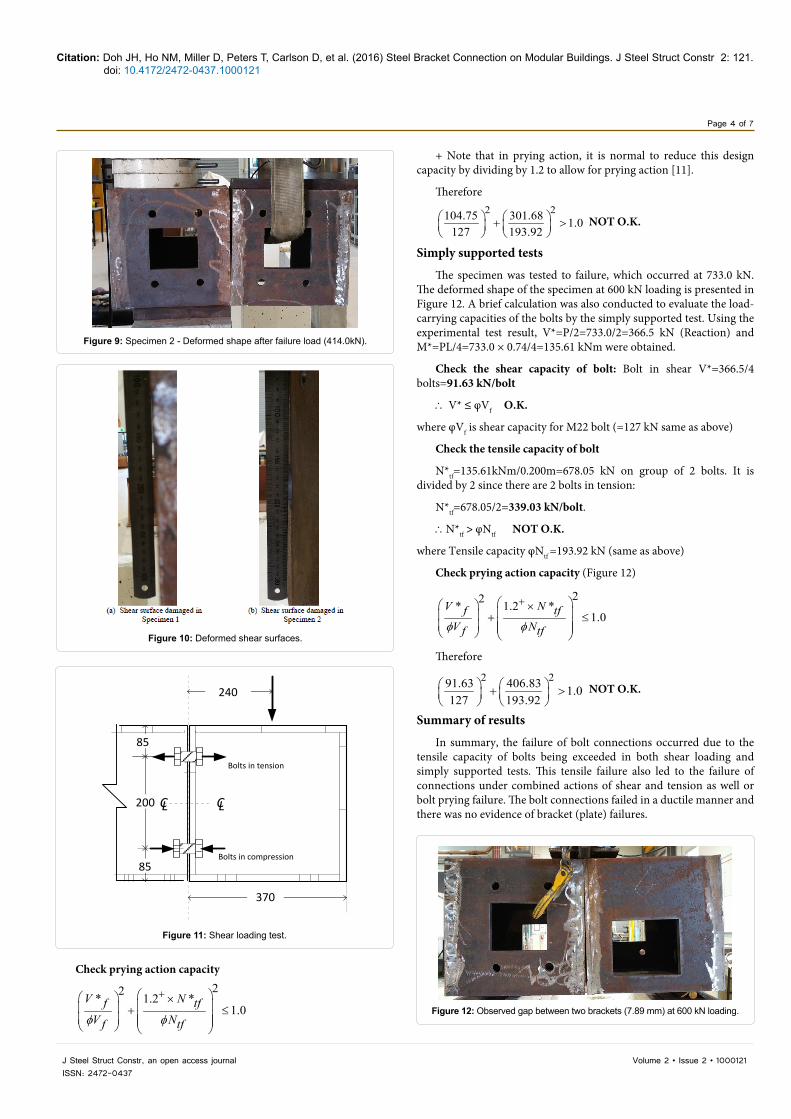
The specimen was tested to failure, which occurred at 733.0 kN. The deformed shape of the specimen at 600 kN loading is presented in Figure 12. A brief calculation was also conducted to evaluate the load-carrying capacities of the bolts by the simply supported test. Using the experimental test result, V*=P/2=733.0/2=366.5 kN (Reaction) and M*=PL/4=733.0 × 0.74/4=135.61 kNm were obtained.
Check the shear capacity of bolt: Bolt in shear V*=366.5/4 bolts=91.63 kN/bolt
∴ V* ≤ φVf O.K.
where φVf is shear capacity for M22 bolt (=127 kN same as above)
Check the tensile capacity of bolt
N*tf=135.61kNm/0.200m=678.05 kN on group of 2 bolts. It is divided by 2 since there are 2 bolts in tension:
N*tf=678.05/2=339.03 kN/bolt.
∴N*tf > φNtf NOT O.K.
where Tensile capacity φNtf =193.92 kN (same as above)
Check prying action capacity (Figure 12)
22* 1.2 *1.0
V Nf tfV Nf tfφ φ
+ × + ≤
Therefore
2 291.63 406.83 1.0127 193.92
+ >
NOT O.K.
Summary of results
In summary, the failure of bolt connections occurred due to the tensile capacity of bolts being exceeded in both shear loading and simply supported tests. This tensile failure also led to the failure of connections under combined actions of shear and tension as well or bolt prying failure. The bolt connections failed in a ductile manner and there was no evidence of bracket (plate) failures.
Figure 9: Specimen 2 - Deformed shape after failure load (414.0kN).
Figure 10: Deformed shear surfaces.
240
200
85
85
370
CLCL
Bolts in tension
Bolts in compression
Figure 11: Shear loading test.
Figure 12: Observed gap between two brackets (7.89 mm) at 600 kN loading.

Page 5 of 7
Citation: Doh JH, Ho NM, Miller D, Peters T, Carlson D, et al. (2016) Steel Bracket Connection on Modular Buildings. J Steel Struct Constr 2: 121. doi: 10.4172/2472-0437.1000121
Volume 2 • Issue 2 • 1000121J Steel Struct Constr, an open access journal ISSN: 2472-0437
Numerical Modelling Using Strand7The numerical modelling, using the computer software Strand7,
presented below, consists of two stages. In the first stage, a benchmark model was carried out using nonlinear static solver for a comparative study. The comparison was based on the failure load values. For the sake of simplicity and saving computational time, the second stage was to investigate the steel bracket connection using linear analysis. The aim was to provide an overview into the structural behaviours of the steel bracket connection when varying the bolthole dimension and bolthole spacing.
Comparative study
The purpose of the numerical model was to simulate the shear loading tests. The faces of the steel boxes were modelled by the use of Quad 4 elements. Rigid links, rigidly connecting nodes together, were used to create the direct contact of adjacent plates. The two steel boxes were connected by four bolts simulated by Hexa 8 brick elements. The restraints for the loaded box were assigned as free to translate and rotate, while the unloaded box was fully fixed. Figure 13 shows the pre-processing of the connection model.
The nonlinear static solver, using an algorithm based on the modified Newton-Raphson method, was used to obtain the response of the structure. Figure 14 presents the displacement response of the two boxes. The displacement of unloaded box was zero; whilst the loaded box had the maximum displacement of 1.54 mm occurring at the far-end. Figure 15 illustrates the stress distribution of the steel bracket connection under loading condition. The ultimate load of the simulation was 547.6 kN, which was overestimated in comparison with the experimental results (419.0 and 414.0 kN). Discrepancies between experimental and numerical results can be attributed to experimental and human errors combined with the idealistic and simplified nature of the numerical techniques (e.g., effects of bolt slip were ignored in the simulation). This model was formed as a baseline and further improvements of the model are necessary (Figures 14 and 15).
Parametric study
Influence of bolt dimension on the performance of steel bracket connection: In this section, a parametric study was carried out to investigate the effect of bolt holes. Those bolt holes were varied in 4 mm increments from 16 mm to 24 mm adhering to the Australian Standards of bolt diameters listed in AS4100. The boltholes had an extra diameter of 2 mm each to allow for construction tolerance. The aim was to observe a linear trend whilst changing the bolt diameters. In Strand7, the two connecting plates with a thickness of 15 mm were attached by four simulated bolts using rigid links. Forces were applied on one of the plates that ranged from 0 to 500 kN at 100 kN increments (Figure 16). The following observations can be made:
Figure 17 represents the force applied at 100 kN intervals from 0 kN to 500 kN and its respective deflection for the nodes at the bottom of the bolthole (a), at the interior of the bolthole (b) and at the midspan between the boltholes (c). Regarding the node at the bottom of the bolthole, the deflection difference between the M16 bolts and the M24 bolts at 500 kN of applied force was 0.94 mm, from 5.04 mm compared to 4.10 mm, respectively. This was not a significant variance in deflection when the same load was applied considering the M16 bolt is two-thirds the diameter of the M24.
It is observed that the interior node deflected more than did the bottom bolthole node and this was due to the local buckling that occurred throughout the plate. The deflection difference between the M16 and M24 bolts at 500 kN of applied force was 0.75 mm, from 5.46 mm compared to 4.71 mm when using the M24 bolts compared to the M16, i.e., it only deflected 80.5% as much. The node at the midspan between the boltholes experienced a greater deflection than either of the nodes at the bottom of the bolthole or the interior of the bolthole. It is believed that the deflection was much greater because of the local buckling that occurred in the plate at this specific region more than near the bolthole region. The midspan node corresponded to the structural
Figure 13: Pre-processing in Strand7.
Figure 14: Displacement of two steel boxes.
Figure 15: Stress distribution of two steel boxes.
Figure 16: Two connecting plates under applied force.
Page 6 of 7
Citation: Doh JH, Ho NM, Miller D, Peters T, Carlson D, et al. (2016) Steel Bracket Connection on Modular Buildings. J Steel Struct Constr 2: 121. doi: 10.4172/2472-0437.1000121
Volume 2 • Issue 2 • 1000121J Steel Struct Constr, an open access journal ISSN: 2472-0437
Figure 17: Applied force versus deflection for different investigation nodes.
Figure 18: Gradient versus bolt diameter for different investigation nodes.
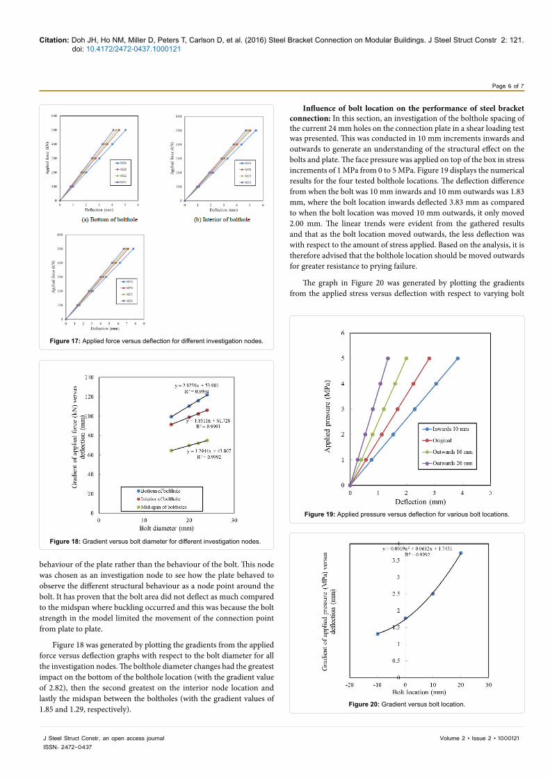
Figure 19: Applied pressure versus deflection for various bolt locations.
Figure 20: Gradient versus bolt location.
behaviour of the plate rather than the behaviour of the bolt. This node was chosen as an investigation node to see how the plate behaved to observe the different structural behaviour as a node point around the bolt. It has proven that the bolt area did not deflect as much compared to the midspan where buckling occurred and this was because the bolt strength in the model limited the movement of the connection point from plate to plate.
Figure 18 was generated by plotting the gradients from the applied force versus deflection graphs with respect to the bolt diameter for all the investigation nodes. The bolthole diameter changes had the greatest impact on the bottom of the bolthole location (with the gradient value of 2.82), then the second greatest on the interior node location and lastly the midspan between the boltholes (with the gradient values of 1.85 and 1.29, respectively).
Influence of bolt location on the performance of steel bracket connection: In this section, an investigation of the bolthole spacing of the current 24 mm holes on the connection plate in a shear loading test was presented. This was conducted in 10 mm increments inwards and outwards to generate an understanding of the structural effect on the bolts and plate. The face pressure was applied on top of the box in stress increments of 1 MPa from 0 to 5 MPa. Figure 19 displays the numerical results for the four tested bolthole locations. The deflection difference from when the bolt was 10 mm inwards and 10 mm outwards was 1.83 mm, where the bolt location inwards deflected 3.83 mm as compared to when the bolt location was moved 10 mm outwards, it only moved 2.00 mm. The linear trends were evident from the gathered results and that as the bolt location moved outwards, the less deflection was with respect to the amount of stress applied. Based on the analysis, it is therefore advised that the bolthole location should be moved outwards for greater resistance to prying failure.
The graph in Figure 20 was generated by plotting the gradients from the applied stress versus deflection with respect to varying bolt

Page 7 of 7
Citation: Doh JH, Ho NM, Miller D, Peters T, Carlson D, et al. (2016) Steel Bracket Connection on Modular Buildings. J Steel Struct Constr 2: 121. doi: 10.4172/2472-0437.1000121
Volume 2 • Issue 2 • 1000121J Steel Struct Constr, an open access journal ISSN: 2472-0437
location (assuming positive location is outwards from centre). This resulted in a parabolic trend in the stress versus deflection gradient with respect to the bolt location.
Conclusion
The study focused on the structural performance of the steel bracket connection. An experimental programme was undertaken to investigate the response of the steel bracket connection under different loading conditions. The steel bracket connections failed in a ductile manner and there was no evidence of plate failures. The analysis revealed that the failure of connections was due to the tensile capacity of the bolts being exceeded, thus led to bolt prying failure. The finite element method using Strand7 software was employed as an analytical method for the comparison of the test results. The model was formed as a baseline. Further improvements in the model are necessary for future comprehensive investigations to ensure design optimisation of the steel bracket connection with respect to multiple variables such as bolthole size, bolthole spacing and also wall thickness of the steel bracket.
Acknowledgement
The authors wish to acknowledge an in-kind contribution from Vataple Group Australia by providing the test specimens.
References
1. Hesler W (1990) Modular Design Where It Fits. Chemical Engineering Process pp: 76-80.
2. Torre DLM (1994) A Review and Analysis of Modular Construction Practices. Theses and Dissertations, Lehigh University, United States.
3. Rogan AL, Lawson RM, Bates-Brkljac N (2000) Value and Benefits Assessment of Modular Construction. The Steel Construction Institute, London.
4. Antill JM, Woodhead RW (1990) Critical Path Methods in Construction Practice. John Wiley and Sons, USA.
5. Wells D (1979) Movement Key to Pre-Fab Module Use. Oil and Gas Journal 77: 148-168.
6. Tomas U, Ganiron JR, Mohammed A (2014) Prefabricated Technology in a Modular House. International Journal of Advanced Science and Technology 73: 51-74.
7. TLG Modular Building Solutions (2016) Photo Gallery, viewed 13 July 2016.
8. Modular Building Institute (2016) Why Build Modular, viewed 13 July 2016.
9. Strand7 Pty Ltd (2010) Using Strand7 Manual. (3rd edn)., Sydney, NSW, Australia.
10. AS4100-1998 (1998) Steel Structures. Standards Association of Australia, NWS, Australia.
11. Hogan TJ, Thomas IR (1994) Design of Structural Connections. Australian Institute of Steel Construction.
Citation: Doh JH, Ho NM, Miller D, Peters T, Carlson D, et al. (2016) Steel Bracket Connection on Modular Buildings. J Steel Struct Constr 2: 121. doi: 10.4172/2472-0437.1000121
OMICS International: Open Access Publication Benefits & FeaturesUnique features:
• Increasedglobalvisibilityofarticlesthroughworldwidedistributionandindexing• Showcasingrecentresearchoutputinatimelyandupdatedmanner• Specialissuesonthecurrenttrendsofscientificresearch
Special features:
• 700+OpenAccessJournals• 50,000+Editorialteam• Rapidreviewprocess• Qualityandquickeditorial,reviewandpublicationprocessing• Indexingatmajorindexingservices• SharingOption:SocialNetworkingEnabled• Authors,ReviewersandEditorsrewardedwithonlineScientificCredits• Betterdiscountforyoursubsequentarticles
Submityourmanuscriptat:http://www.omicsonline.org/submission