steam partial admission
DESCRIPTION
nnTRANSCRIPT

AIAA 2002-3638
Full- and Partial Admission Performance of the Simplex Turbine
Daniel J. Dorney*, Lisa W. Griffin §
NASA Marshall Space Flight Center
Applied Fluid Dynamics Analysis Group
MSFC, AL 35812
Douglas L. Sondak #
Boston University
Office of Information Technology
Boston, MA 02215
ABSTRACT
The turbines used in rocket-engine applications are
often partial-admission turbines, meaning that theflow enters the rotor over only a portion of the
annulus. These turbines have been traditionally
analyzed, however, assuming full-admissioncharacteristics. This assumption enables the
simulation of only a portion of the 360-degreeannulus, with periodic boundary conditions applied inthe circumferential direction. While this traditional
approach to the simulating the flow in partial-admission turbines significantly reduces the
computational requirements, the accuracy of thesolutions has rarely been evaluated. In the current
investigation, both full- and partial-admission three-
dimensional unsteady Navier-Stokes simulations were
performed for a partial-admission turbine designedand tested at NASA Marshall Space Flight Center.
The results indicate that the partial-admission natureof the turbine must be included in simulations to
properly predict the performance and flowunsteadiness of the turbine.
NOMENCLATURE
M - Mach number
p - Static pressurePt - Total Pressure
Tt - Total temperatureW - Work
ot
F11
- Absolute circumferential angle
- Relative circumferential angle
- Total-to-total efficiency
INTRODUCTION
Partial-admission turbines are used in many high-
speed applications, especially in rocket engines. In a
partial-admission environment the flow enters theturbine rotor over only a portion of the completeannulus. Thus, the turbine rotors periodically pass
through flowing regions and regions of no flow. Theturbine airfoils, therefore, operate in an unsteady flow
environment that is strongly dependent on thecircumferential location of the airfoils. Historically,
partial-admission turbines have been analyzed usingfull-admission flow assumptions, namely that the flow
* Aerospace Engineer, Associate Fellow AIAA.Team Leader, Senior Member AIAA.
Senior Scientific Programmer. Senior Member AIAA.
Copyright @2002 by the American Institute of Aeronauticsand Astronautics, Inc. No copyright is asserted in the UnitedStates under Title 17, U.S. Code. The U.S. Government has
a royalty-free license to exercise all rights under the copyrightclaimed herein for Governmental Purposes. All other rights
are reserved for the copyright owner.

isperiodicand that only a portion of the annulus needbe simulated. The impact of this assumption on the
design and predicted performance of partial-admission turbines has not been thoroughly
investigated. Some theoretical and experimentalstudies of partial-admission turbines include theworks of Horlock [1], Boulbin et al. [2], and Huzel
and Huang [3].
The objective of the current study is to characterize
the unsteady and time-averaged flow fields in a
partial-admission turbine by performing full- and
partial-admission simulations of the Simplex turbine.This will help to assess the inaccuracies due to the
full-admission assumption commonly used for design
purposes. The Simplex turbine was designed andtested at NASA Marshall Space Flight Center to study
the use of composite materials in high-speed turbine
geometries. The computational simulations were
performed using a three-dimensional time-dependentNavier-Stokes analysis. The numerical results have
been compared with limited experimental data.
NUMERICAL PROCEDURE
The governing equations considered in this study arethe time-dependent, three-dimensional Reynolds-
averaged Navier-Stokes equations. The algorithmconsists of a time-marching, implicit, finite-difference
scheme. The procedure is third-order spatiallyaccurate and second-order temporally accurate. Theinviscid fluxes are discretized according to the
scheme developed by Roe [4]. The viscous fluxes are
calculated using .standard central differences. An
approximate-factorization technique is used tocompute the time rate changes in the primaryvariables. Newton sub-iterations are used at each
global time step to increase stability and reducelinearization errors. For all cases investigated in this
study, one Newton sub-iteration was performed at
each time step. The turbulent viscosity is calculated
using the two-layer Baldwin-Lomax algebraicturbulence model [5]. Message Passing Interface
(MPI) and OpenMP application program interfaces
(API's) are used for parallel processing to reduce the
computation time.
The Navier-Stokes analysis uses O- and H-type zonal
grids to discretize the flow field and facilitate relativemotion of the rotating components (see Fig. 1). The
O-grids are body-fitted to the surfaces of the airfoilsand generated using an elliptic equation solution
procedure. They are used to properly resolve theviscous flow in the blade passages and to easily apply
the algebraic turbulence model. The algebraically
generated H-grids are used to discretize the remainderof the flow field, including the nozzles.
The computational analysis has been validated onseveral supersonic turbine geometries (e.g., Refs. 6
and 7).
BOUNDARY CONDITIONS
The theory of characteristics is used to determine theboundary conditions at the inlet and exit of the
computational domain. The total pressure, total
temperature, and the circumferential and radial flow
angles are specified as a function of the radius. Theupstream running Riemann invariant is extrapolatedfrom the interior of the computational domain.
At outflow boundary the circumferential and radial
flow angles, total pressure, and the total temperatureare extrapolated from the interior of the computationaldomain. The total-to-static pressure ratio is specified
at mid-span of the computational exit and the pressureat all other radial locations at the exit is obtained by
integrating the equation for radial equilibrium.
Periodicity is enforced along the outer boundaries ofthe H-grids in the circumferential direction.
At solid surfaces the relative velocity is set to zero,
the normal derivative of the pressure is set to zero,and the surfaces are assumed to be adiabatic.
GEOMETRY AND FLOW CONDITIONS
The single-stage supersonic turbine, called Simplex,includes straight centerline nozzles and was designedand tested at NASA Marshall Space Flight Center.
The turbine was tested with both metallic and
composite rotor airfoils, and the time-averaged total
temperatures and total pressures were recorded atseveral locations in the rig.
The Simplex turbine geometry includes 6 straightcenterline nozzles, flowing over half the annulus, and95 rotors. In the full-admission simulation it wasassumed the turbine contained 12 nozzles (i.e.,
equally-spaced flowing nozzles around the annulus)and 96 rotors, with the rotors being scaled by the
factor of 95/96. A l-nozzle/8-rotor model was then
simulated. In the partial-admission simulation the
actual turbine geometry of 6 flowing nozzles
(covering half the annulus) and 95 rotors wassimulated. The spanwise sectional grids for the rotorsin both simulations contained approximately 5,000
grid points. The full-admission simulations utilized 31
spanwise planes, while the partial-admission utilized15 spanwise planes. The use of 15 spanwise planes

wasdeemedacceptablebasedonthelengthscalesoftheunsteadinessassociatedwith thenozzles•Eachstraightcenterlinenozzle was modeledwithapproximately270,000gridpoints.Thus,a totalofapproximately1.3milliongridpointswereusedinthefull-admissionsimulationand approximately7.1milliongridpointswereusedin thepartial-admissionsimulation.Thecomputationalgridsfor thenozzlesandrotorsareshowninFig.1.
Theflowentersthenozzlesat a MachnumberofapproximatelyM=0.25andatotalpressureofPt=801psia.The peakMachnumberin the nozzleisapproximatelyM=2.80.Thetotal-to-staticpressureratioacrossthecompleteturbineisapproximately15.Theoperatingfluid in the rig testswasgaseousnitrogen,whiletheoperatingfluidin theengineandcurrentsimulationsisoxygen.
Both simulationswere run for more thanonecompleterotor revolution.The simulationswereperformedon17to38450-MHzprocessorsofanSGIOrigin2000locatedatNASAAmesResearchCenter.The simulationsrequiredapproximately3x106sec/gridpoint/iterCPUtimeperprocessoron 38processors.
RESULTS
Figures 2 and 3 display Mach number contours in onenozzle from the full-admission and partial-admission
simulations, respectively. The figures represent the
same relative position between the nozzle and therotors. In the full-admission simulation the rotor flow
field exerts a back-pressuring effect on the nozzle,
causing the nozzle exit flow to develop a subsoniccore (see Fig. 2). This is a direct consequence of
assuming flowing nozzles around the completeannulus in conjunction with the known experimental
(partial-admission) exit boundary conditions.
One view of instantaneous Mach contours for the
entire turbine (nozzles and rotors) in the full-
admission and partial-admission simulations areshown in Figs. 4 and 5, respectively. In the partial-admission simulation the thick wakes associated with
the solid wall regions between adjacent nozzles are
clearly visible. The low-speed flow regions outsidethe influence of the nozzles are also evident near the
bottom of Fig. 5. In the full-admission simulation thesubsonic flow region at the nozzle exit causes a higher
static pressure entering the rotor. Therefore, there is a
greater acceleration in the rotor to achieve theprescribed exit pressure. The relative Mach number in
the full-admission simulation remains supersonic to
the turbine exit.
A second perspective of the instantaneous Machcontours is shown in Figs. 6 and 7. The non-uniformflow across the nozzle exit is observed in Fig 6,
followed by high-speed flow throughout the rotor.This phenomenon washes out the wakes created bythe solid wall region between adjacent nozzles. The
partial-admission solution contains a large region of
low speed flow outside the influence of the flowingnozzles, except for the flow carried along in blade
passages by the rotating blades.
•Tables 1 and 2 contain the mass- and time-averaged
flow quantities at the inlet and exit of the nozzles androtors, respectively. The flow quantities at the nozzleinlet are similar, except the mass flow in the full-admission simulation is twice that of the partial-
admission simulation. The average Mach number and
total pressure are higher at the nozzle exit in the
partial-admission simulation. As noted earlier, thedifferences are caused by the rotor exerting a strong
back pressure effect in the full-admission simulation.
The large differences in the rotor inlet and exitconditions are the result of including the region of lowflow outside the influence of the flowing nozzles in
the averaging process for the partial-admissionsimulation. Confining the averaging process to the
regions of the annulus influenced by the flowingnozzles results in closer agreement of the flow
quantities, but disregards the important partial-admission flow phenomena. The efficiency and workin the full-admission simulation are, as expected,
greater than in the partial-admission simulation. In theexperiments the determination of the efficiency wasbased in part on three probes located at differentcircumferential locations at the exit of the rotor. Two
of the probes were located within the influence of theflowing nozzles, while one was in the low flow
region. Thus, the experimental efficiency of 60.5%should be biased towards the value predicted in thefull-admission simulation. Indeed, the experimental
efficiency is bracketed by the predicted partial-admission value of 50.4% and full-admission value of
63.3%. The discrepancies between the experimental
and predicted efficiencies are likely the result of manysources, including: a) the tests were run in nitrogenand the simulations were run for oxygen, b) the
limitations of the computational grid density, and c)
only a small number of data acquisition locationswere used in the experiments because the focus of the
program was the turbine materials.
Figure 8 displays unsteady pressure envelopes at threespanwise locations from the full-admission

simulation.Figure9 displayssimilarenvelopesfromthepartial-admissionsimulationwhenthebladesaremovingthroughthehalf of theannuluswith theflowingnozzles,whileFig.10displaystheenvelopesfromthepartial-admissionsimulationwhenthebladestraverseboththeflowingandnon-flowingregions.Bothsimulationsexhibitrelativelyconstantloadingacrossthespan,whilethefull-admissionsimulationindicatessignificantlymoreunsteadiness.It is worthnotingthattherotordoesnot becomecompletelyunloadedasit movesthroughtheregionoutsideoftheflowingnozzles.
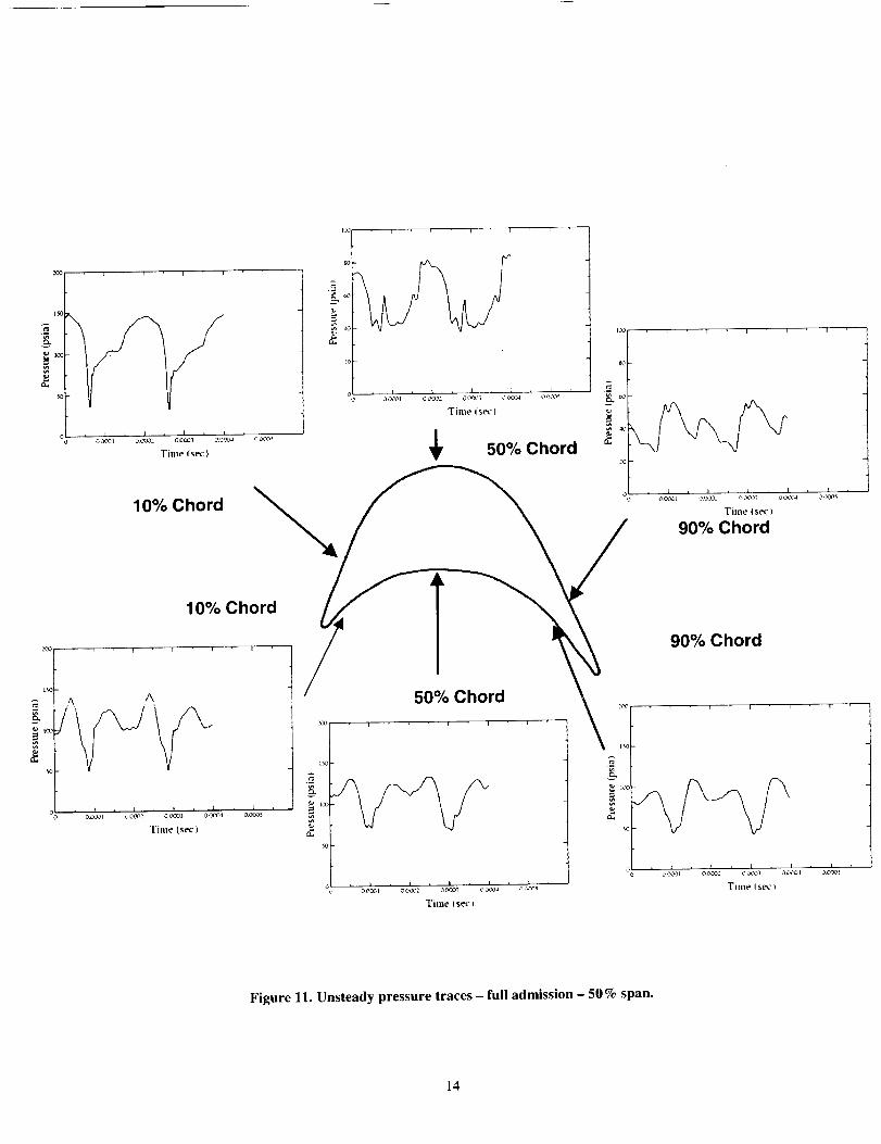
Unsteadypressuretracesat variouslocationsalongthemidspanof therotorareshownfor thefull-admissionsimulationsin Fig.11.Figures12and13showtracesfrom thepartial-admissionsimulationcorrespondingto the bladesmovingthroughtheflowingportion(Fig.12)andboththeflowing/non-flowingportionsoftheannulus(Fig.13).Figures14to 16 contain the Fourier decompositionscorrespondingto thepressuretracesin Figs.11-13,respectively.In the full-annulussimulationthedominantunsteadinesson thesuctionsurfaceis thenozzle-passingfrequency(approximately5000Hz),while thepressuresurfaceexperiencessignificantunsteadinessat boththefundamentalandtwicethenozzle-passingfrequency.Theharmoniccontentisgeneratedbytwosources:a) thepressurevariationsacrossthenozzleexit shownin Fig.2, andb) thereflectionof therotorbowshockoff thesolidregionbetweenadjacentnozzles.Thedominantunsteadinesswhentherotorsarein thenozzlejetsin thepartial-admissionsimulationis at the nozzle-passingfrequency,although a moderateamount ofunsteadinessis alsopresentat twicethe nozzle-passingfrequency.As expected,whenthe rotortraversesbothflowingandnon-flowingregionsinthepartial-admissionsimulationthe higherharmoniccontent(especiallythatassociatedwith rotorbowshockreflection)is reducedandmorelow-frequencycontentisobserved.It is interestingtonotethatevenwhentherotorsareoutsidetheflowingnozzleregionstheystill experienceunsteadinessassociatedwiththenozzle-passingfrequency,albeitata lowerlevel.Thisimpliesthatthe interactionsbetweentherotorsandnozzlesdrivetheunsteadinessof theentiresystem,notjusttheflowingportionoftheannulus.
Theunsteadyaxial,radialandtangentialforcesontherotorsfromthetwosimulationsareshowninFig.17.Theoveralllevelsof theforcesaresimilarin bothsimulations.The forces in the full-admissionsimulationexhibittwo peaksasthe rotorsmovethroughthenozzleflow.Thesepeaksaregeneratedbythepresenceofthesubsonicflowoveraportionofthe
nozzleexit(showninFig.2).Asexpectedtheresultsof thepartial-admissionsimulationindicatethattherotorswindmillwhenoutsidethe regionof theflowingnozzles.
CONCLUSIONS
Full- and partial-admission unsteady three-dimensional simulations have been performed for a
partial-admission supersonic turbine designed andtested at NASA Marshall Space Flight Center. The
results of the partial-admission simulation show
favorable agreement with the design Mach numbersand velocity triangles of the nozzles and rotors. Theresults of the full-admission simulation exhibit fair
agreement with the experimental efficiency, whichwas determined by probes biased towards the flowing
regions of the annulus. The full- and partial-admissions simulations gave significantly differentnozzle exit flow profiles and rotor velocity fields.
The partial-admission rotor exit relative Mach numberis subsonic, as is the design intent. In the full-admission simulation, however, the relative Mach
number remains supersonic to the rotor exit. Thedifferences between the results of the two simulationsunderscore the need for modeling the complete
annulus for partial-admission geometries.
ACKNOWLEDGEMENTS
The authors would like to acknowledge the use of the
supercomputer facilities at NASA Ames ResearchCenter, and especially thank Mr. Chuck Niggley and
Mr. Herbert Yeung for their assistance. The authorswould also like to thank Mr. Matt Marsh of
NASA/MSFC for his help in interpreting the
experimental data.
REFERENCES
1. Horlock, J. H., Axial Flow Turbines, Chapter 7,Butterworth, London, 1966.
2. Boulbin, F., Penneron, N., Kermarec, J. andPluviose, M., "'Turbine Blade Forces Due toPartial Admission," Revue Francaise de
Mecanique, 1992-1993.
. Huze[, D. K. and Huang, D. H., Design of Liquid-
Propellant Rocket Engines, AIAA Progress inAstronautics and Aeronautics, Vol. 147, A.
Richard Seebass Editor-in Chief, Chapter 6,
1992.

4.
.
.
.
Roe, P. L., "'Approximate Riemann Solvers,Parameter Vectors, and Difference Schemes, _'
Journal of Computational Physics, Vol. 43, 1981,
pp. 357-372.
Baldwin, B. S., and Lomax, H., "'Thin Layer
Approximation and Algebraic Model forSeparated Turbulent Flow," AIAA Paper 78-257,Huntsville, AL, January, 1978.
Griffin, L. W. and Dorney, D. J., "'Simulations of
the Unsteady Flow Through the Fastrac
Supersonic Turbine," ASME Journal ofTurbomachinery, Vol. 122, No. 2, April, 2000,
pp. 225-233.
Dorney, D. J., Griffin, L. W., and Huber, F., "'AStudy of the Effects of Tip Clearance in a
Supersonic Turbine," ASME Journal ofTurbomachineo,, Vol. 122, No. 4, October, 2000,
pp. 674-673.
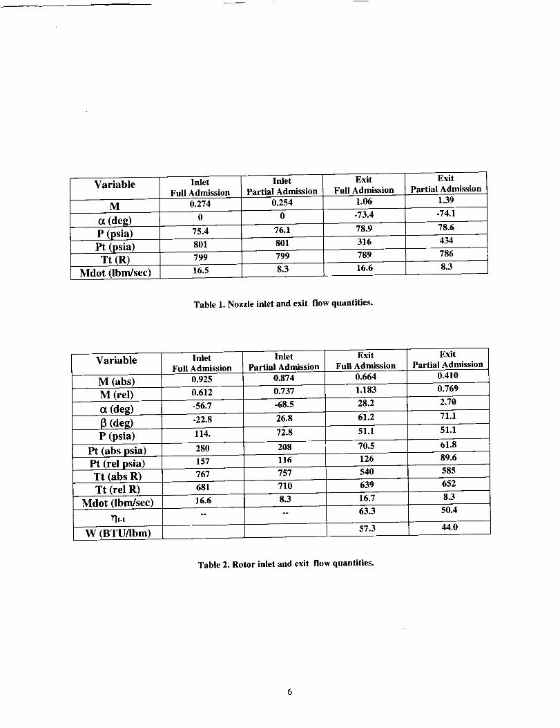
Variable
M
(deg)
P (psia)
Pt (psia)
Tt (R)
InletFull Admission
0.274
75.4
801
Inlet
Partial Admission
0.254
76.1
Exit
Full Admission
1.06
-73.4
78.9
801 316
Exit
Partial Admission
1.39
-74.1
78.6
434
799 799 789 786
Mdot (lbm/sec) 16.5 8.3 16.6 8.3
Table 1. Nozzle inlet and exit flow quantities.
Variable
M (abs)
M (rel)
(deg)
[_ (deg)
P (psia)
Pt (abs psia)
Pt (rel psia)
Tt (abs R)
InletFull Admission
0.925
0.612
-56.7
-22.8
Inlet
Partial Admission
0.874
0.737
-68.5
26.8
ExitFull Admission
0.664
1.183
28.2
61.2
ExitPartial Admission
0.410
0.769
2.70
71.1
114. 72.8 51.1 51.1
280 208 70.5 61.8
157 116 126 89.6
767 757 540 585
Tt (relR) 681 710 639 652
Mdot (lbm/sec) 16.6 8.3 16.7 8.3-- 63.3 50.4
_t-t
W (BTU_bm) 57.3 44.0
Table 2. Rotor inlet and exit flow quantities.

Q_
_mL
C_
0
Q_i-I
ml
0L_N
C_

Figure 2. Instantaneous Mach contours - nozzle - full admission.
Figure 3. Instantaneous Mach contours - nozzle - partial admission.

Figure4.InstantaneousMachcontours-upstreamview-full admission.
Figure5.InstantaneousMachcontours- upstreamview- partialadmission.

Figure6.InstantaneousMachcontours-downstreamview-full admission.
Figure7.InstantaneousMachcontours- downstreamview- partialadmission.
10

_" P/Pt o P/Pt_I 0 0 0' 0 _ 0 i_ 0 0 __ 0 la
0 ' "",I "'," _ I " -_" _" _'--'--I-- _ I ' 0 ' ',.'!:.... ' I _.l_ 4- i"
'_ o -' ! ¢1 io :,: / t \ \ 7 i''i i/ J
. :_' _ ,I _ I..: ) "_ \ '_ I _ I
: : _ I_ il _ I•-, : # i I I • I
_ : i' / ! zl._" I
- _ _ i _! , I I = _ " -i f ',
i " :' I i # I _,- : :/ p
: ! /' /
I • J i tx,,. ';I._;;// c/ . :, , I_.--I: /:," / r l_'i./-I °F i :_ , Ii_-_,1: :l i ",17 _ _// .. ,,• : I / I,_ _ _" I I" !
: ", t ' I I : "i I' ' '/" • ". <, ; ) .:,:_.__-_" ._7'"i_l!:Z_'-I -'_, I , I , I , /
X
oo
P/Pt9' P
o .o _ o u
le:: .l i /
t !
I,:_ / i I # l
." i _
: i J ",,,I
:" 1 /ii 'i I
_J
I
i / \/ \1
" " ' l / #• _ ,I / //
/: _
;i t I
I )I /° //
/7 I._t l , I I * I ,

0.25
0.2
I I 1 I
13.3% Span _ .......Time-A_$
X/C
0.2_
0.2
O.IS
O.l
0.05
I I I I
i=I .°,.....1- M_imum|
50% Span T_"_-a'_l
i_._ _ _ -- _ _. I _ -- _ _ __. _'_\
I/ \ \
,%
'_----_ ..... ..-..i_:" : _ ...... ::. ........... .....
, I , I , I , I ,
0.2 0.4 0.6 0.$
XIC
0,_
0.2
0.[
| I I :
I 86.7% Span h,,_,..... /Time-A_g]
f \
\
. I .,.
0.2 0.4 O.O O.S
XIC
Figure 9. Rotor unsteady pressure envelopes - partial admission in nozzle jets.
12

0.25
0.1
0.05
I i I
13.3% Span [
I
Maximum
Tlme-A ,_
x. \
• ........ _-='- :- _.
0 _ I _ I t I , I
0 02 0.4 O0 0.8
X/C
0.25
0.2 _
-"_l / X\
\0.15
O.L
0.05
1 I
It la xltllutrl
T*me-A_
\
....... ....
02 0.4 0.0 0.8
X/C
0.25 Time-A_gJ
//." "_\ \_
0. t5 / \
0.1
0 _ I * I * I _ 102 0.4 0.0 0.$
X/C
Figure 10. Rotor unsteady pressure envelopes - partial admission in all regions.
13
,,_I , , , , ,
h._
!,3 gO
0 ---- --Tillle(sP_) 50 go Chora ,_
10% Chord Ti,._ (,_-)90% Chord
10% Chord q I "_,_, . , . , . 90% Chord
:i _'' .A / 50!/oChord '0
"5
, I ) , I _ , _ "
Time (sec) _
i I d i I I
" ' oog,' 0_ ' oo..:_' o,_,_, T,,._(,_-)OOO01
Time ( sec )
Figure 11. Unsteady pressure traces - full admission - 50 % span.
14

Z
o o_'_oI oooo_ o o,3o_ 0ooo4 o..ooc_
Time (s_)
10% Chord
so
40
2Q
_S [o0 i
' ' ' o._: ' ' ' ' ' oo_, ' t_ _oooo ) oc,:,.',.4
Time (s_)
50% Chord °
-,,,.10% Chord
2_0
2O0 I J I _ : '
o _
...... Tml;: ,osec )
ooc_'_ o o_o
Time _sec)
i l j l
0.00_5
Time (sec)
90% Chord
90% Chord
Time (sec)
Figure 12. Unsteady pressure traces - partial-admission - 50% span - in nozzle jets.
15

In Nozzle Jets _'_
j i '°I$0 _ 4_
2O
[i o oooos ,:oo_ aolo_ oce2
Time (sec)
Out of Jets
0 10_5
'Tv'secl__ 5 oL , LChord .......... _,_
/!
Time (sec)
90% Chord
90% Chord
* I I /
000OI '3COl 0,OO B
Time (sec)
Figure 13. Unsteady pressure traces - partial-admission - 50% span - in and out of nozzle jets.
16

!o
C
Ft_-qtlency IHz) _,,&
50% Chord _ Frequency i Hz)
Figure 14. Decomposition of unsteady pressure - full.admission - 50% span.
17

isl-
_ _o
< rr
_°;
2O
E<
Frequenc v (Hz)
_' 50% Chord
N<&
, ' 2 ' :,__o
Ftequency (Hz) /
10% Chord /
[10% Chord
k
_- I
_ ioo.'o 2o2_ /,oooo ._'ooo
Ftequency (Hz)
4_:._ _-
E.<
i i i
II
Freqt_ency (Hz)
90% Chord
90% Chord
-_, _-_--_ _ -
Ft+equenc • (Hz)
Figure 15. Decomposition of unsteady pressure - partial-admission - 50% span - in nozzle jets.
18

6[
•slo.l'jo ]no puu u! - uvds %0_ - uo!ss!mpu'lV!_zvd - o.mss_ad £pvo_sun jo uo!l!sodmo_o(I "9I oJn3!A
, _ _ ,-.,_ F-,¢_ ,_ i _-i rl r
-
r _ , i i
pJoqo %06
pJoqo %06
(z H _ _u_lb_l=I
ol
, F I , I
g -
.[ g'
/pJoqo %0_; _k
e.-.
c¢o_- _ oo[_: oooot
I
pJoqo %0 L
pJoqo %0 I,
(ZH) ,(_ua*[_J:l
oooc¢ 0ooo4: o__x , _._ol , o o
Ol
, i

Full Admission
Partial Admission
In Nozzle Jets
• -- Axial Fo,ce
R_dl al Force
T_ns_nll al F_ce
IO_
i
-10 - x _
-20 , I , I0 O.0031 0.0002
\
0.0_3
Time (sec)
[ i I
00004 00005
c
O
2O
-tO
-2O
I I I I I
RAdiil FoLc¢ I
T.m_..,J at t=_.ceJ
I , I , I , I , I
0.0001 0.0002 0.0003 0.0004 0.0<305
Time isec)
Partial Admission
In/Out of Nozzle
Jets
OU-
-L0
-2O
I I I
R =.-qal Foto_
Ten g_,_ al F_ce
I , I , I
O000S O.OOl 0 001-_
Time (sec
.OO2
Figure 17. Unsteady forces.
20

21