steam humidifier defensor mk5 - climatech-sa.com · 4 1 introduction 1.1 to the very beginning we...
TRANSCRIPT

Defensor Mk5
Technical Documentation
Steam humidifier
1115
661
EN
030
9


Contents
1 Introduction 41.1 To the very beginning 41.2 Notes on the technical documentation 4
2 For your safety 5
3 Product overview 63.1 Unit types 63.2 Standard delivery 73.3 Humidification system overview 83.4 Steam humidifier construction 83.5 Functional description 9
4 Basic planning 104.1 Selecting the unit 104.2 Selecting the control system 134.3 Options 154.4 Accessories 164.4.1 Accessories overview 164.4.2 Accessory details 174.5 Additional planning instructions 19
5 Mounting and installation works 205.1 Safety instructions for mounting and installation works 205.2 Unit fitting 205.2.1 Humidifier location 205.2.2 Mounting the humidifier 225.2.3 Inspecting the installed unit 225.3 Steam installation 235.3.1 Positioning and mounting of the steam distribution pipes 235.3.2 Positioning and mounting of the fan unit 265.3.3 Installing the steam hose 275.3.4 Installing the condensate hose 285.3.5 Inspecting the steam installation 295.4 Water installation 305.4.1 Performing the water installation 305.4.2 Inspecting the water installation 325.5 Electric installation 335.5.1 Electric installation overview 335.5.2 Wiring diagram 345.5.3 Notes on component installation 365.5.4 Inspecting the electrical installation 39
6 Operation 406.1 Unit configuration 406.2 Putting into operation 426.3 Taking out of operation 436.4 Interrogation of the operating status 446.5 Setting the operating parameters 486.6 Maintenance 536.6.1 Notes on maintenance 536.6.2 Dismantling and re-assembly work 546.6.3 Notes on cleaning 576.6.4 To reset the maintenance indication 576.7 Fault elimination 586.7.1 Fault indication 586.7.2 What, if..? 596.7.3 Replacing unit fuses 616.7.4 Resetting fault indication “Error” 61
7 Technical data 62

4
1 Introduction
1.1 To the very beginning
We thank you for having purchased the steam humidifier Defensor Mk5.
The steam humidifier Defensor Mk5 incorporates the latest technical advances and meets all recog-nized safety standards. Nevertheless, improper use may result in danger to the user or third parties and/or impairment of material assets.
To ensure a safe, proper, and economical operation of the steam humidifier Defensor Mk5, pleaseobserve and comply with all information and safety instructions contained in the present technicaldocumentation.
If you have questions, which are not or insufficiently answered in this documentation, please contactyour Defensor supplier. They will be glad to assist you.
1.2 Notes on the technical documentation
Limitation
The subject of this technical documentation is the steam humidifier Defensor Mk5 in the versions:“Visual” and “Process”. The various accessories (humidistats, water filter, etc.) are only described insofaras this is necessary for proper operation of the equipment. Further information on accessories can beobtained in the respective instructions.
This technical documentation is restricted to:
– the planning of a humidifying system that is to be equipped with a steam humidifier Defensor Mk5
– the installation, commissioning, operation and servicing of the steam humidifier Defensor Mk5
The technical documentation is supplemented by various separate items of documentation (spare partslist, installation instructions for electrical installation, etc.). Where necessary, appropriate cross-references are made to these publications in the technical documentation.
Conventions
This symbol draws attention to safety instructions and warnings of potential dangerwhich, if unheeded, could result in injury to persons and/or damage to property.
Safekeeping
Please safeguard this technical documentation in a safe place, where it can be immediately accessed.If the equipment changes hands, the documentation should be passed on to the new operator. If thedocumentation gets mislaid, please contact your Defensor supplier.
Language versions
This technical documentation is available in various languages. Please contact your Defensor supplierfor information.
5
2 For your safety
Intended use
Steam humidifiers Defensor Mk5 are intended exclusively for direct or indirect roomhumidification or for humidification in laboratory and process applications within thespecified operating conditions. Any other type of application, without the written consentof your Defensor supplier, is considered as not conforming with the intended purpose. Themanufacturer/supplier cannot be made liable for any damages resulting from improperuse. The user bears full responsibility.Operation of the equipment in the intended manner requires that all the information inthese instructions is observed (in particular the safety instructions).
General safety instructions
– The steam humidifier Defensor Mk5 must only be installed, operated serviced and inall cases repaired only by persons who are adequately qualified to undertake suchwork and are well acquainted with the product. Ascertaining the qualifications is thecustomer‘s responsibility.
– Caution, danger of electric shock! The Defensor Mk5 is operated with mainsvoltage. Before commencing work on the Defensor Mk5, the unit is to be renderedinoperative in accordance with section 6.3 and prevented from further inadvertentoperation ( isolate unit from the electrical power supply, isolate water supply).
– Observe all local safety regulations.– relating to the operation of mains-operated electrical and electronic equipment– and the provision of water, steam and electrical installations
– Poorly maintained humidification systems can endanger health. The servicing inter-vals should therefore be adhered to without reservation and the servicing workcarried out correctly.
– If it is suspected that safe operation is no longer possible, then the Defensor Mk5should immediately be shut down and secured against accidental power-up. Thiscan be the case under the following circumstances:– if the Defensor Mk5 is damaged– if the Defensor Mk5 is no longer operating correctly– if connections and/or piping are not sealed or cables are loose
– The Defensor Mk5 must only be operated under the specified operating conditions(see section 7).
– The Defensor Mk5 is protected according to IP21. Make sure the units are installed ina drip-proof location
– Caution! If the Defensor Mk5 is installed in an area without a water drain, water sensorsmust be fitted in the area, such that in the event of leakage in the water system, the waterfeed is safely shut off.
– Caution, danger of corrosion! In order to avoid damage, no corrosion-sensitivecomponents should be located in the area of the aerosol streams.
– No work/repair should be carried out on the Defensor Mk5 other than that described inthese instructions.
– Use exclusively original accessories and spare parts available from your Defensorsupplier.
– No modifications must be undertaken on the Defensor Mk5 without the expresswritten consent of Axair Ltd.

6
3 Product overview
3.1 Unit types
The steam humidifiers Defensor Mk5 are available in 2 different type series:
– VisualFor direct or indirect room air humidification with standard requirements for control precision.
– ProcessFor direct or indirect room air humidification in laboratory and process applications where thereare increased requirements for control precision.
Basically, the devices of both type series are of the same construction except for the level control andelectronics. The Visual units >10 kg/h are equipped with a combined contactor/electronic control anda level unit with a single float. To achieve a higher level of accuracy the Process units include a dedicatedelectronic control with special control software and are equipped with a level unit comprising two floats.
They are available in versions suitable for operation with untreated water (with lime collector tank)or with fully demineralized water (without lime collector tank). All versions are equipped, asstandard, with an operating and display unit, by means of which the current operating parameters canbe read and the equipment configured for operation, and an integrated PI controller. The equipmentcan be supplied with various other options.
Type overview and type designation
The units of both type series are available in various versions with different steam capacities andlayout of the power section (heating voltage). The following table provides an overview of the variousmodels and their capacity ranges.
Defensor Mk5 Visual..-../Process..-.. Heating voltage
small large Double unit large
5 8 10 16 20 24 30 40 50 1) 60 1) 80 1)
max. steam capacity in kg/h
5.0 8.0 10.0 16.0 20.0 24.0 30.0 40.0 50.0 60.0 80.0 400V/3~/50…60Hz
4.6 7.3 9.0 14.6 18.0 21.9 27.0 36.2 45.0 54.0 72.4 220V/3~/50…60Hz 2)
5.1 8.4 10.3 16.7 20.6 25.1 30.6 41.5 51.4 61.7 83.1 415V/3~/50…60Hz
5.1 8.7 10.3 --- --- --- --- --- --- --- --- 240V/1N~/50…60Hz
5.1 8.0 10.0 --- --- --- --- --- --- --- --- 230V/1N~/50…60Hz
3.9 5.8 7.1 11.6 14.3 17.4 21.5 28.8 35.7 43.0 57.7 200V/3~/50…60Hz
1) Mk5 ... 50 ... Mk5 ... 60 ... Mk5 ... 80 ...Unit A: 20 kg/h 30 kg/h 40 kg/hUnit B: 30 kg/h 30 kg/h 40 kg/h
2) Process units only

7
The type designation is structured as follows:
Designation Code
Brand name Defensor
Product line Mk5
Type series – Direct or indirect room humidification Visual– Humidification for laboratory and process applications Process
Operating mode – Operation with untreated water (with lime collector tank) –– Operation with fully demineralized water VE (without lime collector tank)
Steam capacity in kg/h – 5, 8, 10, 16, 20, 24, 30, 40, 50, 60 or 80 ..
Heating voltage – 400V/3~/50…60Hz 400V/3~– 220V/3~/50…60Hz (Process units only) 220V/3~– 415V/3~/50…60Hz 415V/3~– 240V/1N~/50…60Hz 240V/1N~– 230V/1N~/50…60Hz 230V/1N~– 200V/3~/50…60Hz 200V/3~
3.2 Standard delivery
The standard delivery includes:
– Steam humidifier Defensor Mk5 compl. (according to type designation) equipped with the desiredoptions (remote operating and fault indication, pressure compensation kit, etc.) according to chap-ter 4.3
– Fixing set including dowels and fixing screws (for single units up to 40 kg/h), mounting profile withdowels and fixing screws (for double units 50...80 kg/h)
– Technical documentation
– Spare parts list (red)
– Ordered accessories (steam distribution pipe, steam hose, etc.) according to chapter 4.4
8
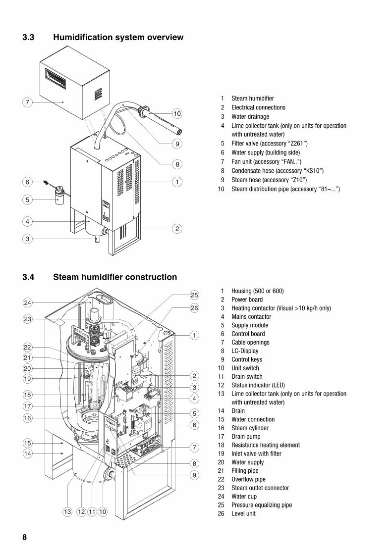
3.3 Humidification system overview
1 Steam humidifier2 Electrical connections3 Water drainage4 Lime collector tank (only on units for operation
with untreated water)5 Filter valve (accessory “Z261”)6 Water supply (building side)7 Fan unit (accessory “FAN..”)8 Condensate hose (accessory “KS10”)9 Steam hose (accessory “Z10”)
10 Steam distribution pipe (accessory “81–...”)
3.4 Steam humidifier construction
1 Housing (500 or 600)2 Power board3 Heating contactor (Visual >10 kg/h only)4 Mains contactor5 Supply module6 Control board7 Cable openings8 LC-Display9 Control keys
10 Unit switch11 Drain switch12 Status indicator (LED)13 Lime collector tank (only on units for operation
with untreated water)14 Drain15 Water connection16 Steam cylinder17 Drain pump18 Resistance heating element19 Inlet valve with filter20 Water supply21 Filling pipe22 Overflow pipe23 Steam outlet connector24 Water cup25 Pressure equalizing pipe26 Level unit
5
6
4
3
7
1
2
10
8
9
23
1
26
2
3
4
5
6
7
8
9
10111213
15
14
17
16
18
19
20
21
22
2425

9
3.5 Functional description
The Defensor Mk5 steam humidifier is an unpressurized steam generator for direct (with fan unit) andindirect (with steam distribution pipe) room air humidification in ventilating and air-conditioning systems.In conjunction with a steam distribution pipe “Process” the unit may be used for humidification inlaboratory and process applications.The Defensor Mk5 operates on the resistance heating principle and is therefore suitable for operationwith raw water, fully demineralized water and partially softened water.
Water supply
The water is taken via a filter valve (accessory “Z261”) to the steam humidifier. It reaches the steamcylinder via the inlet valve (level controlled) and the open water cup.
Level regulation
The water level in the steam cylinder is continuously monitored with the level unit. If the water levelreaches a preset level (owing to the evaporation process) the level unit supplies a signal to the controller.This opens the inlet valve and the steam cylinder is filled up. When the preset operating level is reached,the level unit supplies another signal to the controller to close the inlet valve.The pressure equalizing pipe between the steam connection and the level unit ensures that the waterlevels are the same in the steam cylinder and the level unit.
Steam generation regulation
The steam is produced in the steam cylinder by several resistance heating elements. An external or theinternal regulator for connection as required control the steam production fully variably from 0 to 100 %.
Flushing
The evaporation process increases the concentration of minerals in the water of the steam cylinder. Asuitable volume of water must be flushed through the steam cylinder from time to time and replaced byfresh water to ensure that this concentration does not exceed a specific value unsuitable for operation.The Mk5 steam humidifier performs an auto-adaptive flushing. This consists of the following two formsof flushing:
– Automatic flushing takes place as soon as the water in the steam cylinder exceeds the upperoperating level (e.g. by foaming of the water).
– Flushing dependent on time performs the flushing process at preselected time intervals (seesection 6.1 “Adjustments”).
Automatic or time-dependent flushing takes place depending on the water quality and the operatingdata. If the lowest operating level is reached during the flushing process, the inlet valve remains openuntil the water level in the steam cylinder has reached the normal working level again. If the lowestoperating level is not reached, the inlet valve is closed.
Lime collector tank
The minerals precipitated by the evaporation process accumulate at the bottom of the steam cylinder.Units designed for operation with untreated water are equipped with an additional lime collector tanklocated directly underneath the steam cylinder. This way the minerals do not accumulate in the steamcylinder but mainly in the collector tank thus extending the service intervals and reducing themaintenance costs.
Units designed for operation with fully demineralized water do not have a lime collector tank as fullydemineralized water contains only small amounts of minerals.

10
4 Basic planning
All the data necessary for the selection and layout of a Defensor Mk5 humidifier system are providedin the following chapters. The following planning steps are required:
• Selecting the unit (see chapter 4.1)
• Selecting the control system (see chapter 4.2)
• Selecting options (see chapter 4.3)
• Selecting accessories (see chapter 4.4)
4.1 Selecting the unit
The selection of the unit is reflected in the type description:
1. Application
2. Supply water quality
3. Required maximum steam capacity
4. Required heating voltage
1. Application
The type series can be selected on the basis of the following table:
Scope of use Type series
For direct or indirect room air humidification withstandard requirements for control precision.
Visual
For direct or indirect room air humidification inlaboratory and process applications where thereare increased requirements for control precision.
Process
Achievable control precision
– Visual: ±5 %rh (assuming optimum control distance, PI-control and use of untreated water)±2 %rh (assuming optimum control distance, PI-control and use of fully demineralized water)
– Process: ±2 %rh (assuming optimum control distance, PI-control and use of untreated water)±1 %rh (assuming optimum control distance, PI-control and use of fully demineralized water)
2. Supply water quality
Description
unit with a lime collector tank for operation with untreat-ed water and partially softened water.
Unit without a lime collector tank for operation with fullydemineralized water with a conductivity value <15 µS.Caution! Unit without lime collector tanks should notbe operated with untreated water or partially softenedwater.
Version
–
VE
Defensor Mk5 Visual VE 24-400V/3~
Defensor Mk5 Visual VE 24-400V/3~
Defensor Mk5 Visual VE 24-400V/3~

11
3. Calculating the maximum required steam capacity
The maximum required steam capacity is calculated from the following formulas:
V • ρmD = • (x2 - x1)
1000
VmD = • (x2 - x1)
1000 • ε
mD: maximum steam demand in kg/hV: volume of supply air portion per hour in m3/h (for indirect room humidification) or room volume to
be humidified per hour in m3/h (for direct room humidification)ρ: specific gravity of air in kg/m3
ε: specific volume of air in m3/kgx2: desired absolute room air humidity in g/kgx1: minimum absolute supply air humidity in g/kg
The values for ρ, ε, x2 and x1 can be gathered from the h,x-diagram or the Carrier-Diagram for moistair respectively.
For a rough estimate of the calculated steam capacity, the following table can be used. The values listedin the table are based on a desired room air temperature of 20°C and a desired relative room air humidityof 45 %rh.
Max. portion of supply air in m3/hr or room max. steamvolume to be humidified per hour in m3/hr capacity in kg/h
Temperature / rel. humidity of supply air-15 °C / 90 %rh -5 °C / 80 %rh 5 °C / 60 %rh
650 850 1000 5
1000 1350 1600 8
2000 2650 3200 16
2500 3300 4000 20
3000 4000 4800 24
3750 5000 6000 30
5000 6600 8000 40
6250 8250 10000 50
7500 9900 12000 60
10000 13200 16000 80
Example:
Max. portion of supply air 3000 m3/h, temperature/
rel. humidity of supply air -15°C/90%rh
or
Defensor Mk5 Visual VE 24-400V/3~
Important notes:
– The listed formulas and values from the tables do not consider absorption or release of humidity ofmaterials located in the room being humidified.
– It is absolutely crucial to carefully calculate the maximum steam capacity. Over-dimensionedsteam humidifiers interfere with the control stability.
– For systems where the max. required steam capacity varies extensively (e.g. for test facilities or forsystems with variable air volume flow, etc.), please contact your Defensor supplier.

12
4. Heating voltage/control voltage
Heating voltage
The Defensor Mk5 steam humidifiers are available with various heating voltages. The maximumachievable steam capacity and the power consumption are directly dependent on the selectedheating voltage (see table).
Defensor Mk5 Visual VE 24-400V/3~
400 V/3~50…60 Hz
220 V/3~50…60 Hz
415 V/3~50…60 Hz
240 V/1N~50…60 Hz
230 V/1N~50…60 Hz
200 V/3~50…60 Hz
kg/h kW
... 5-..
Defensor Mk5Visual.../Process...
A kg/h kW A kg/h kW A kg/h kW A kg/h kW A kg/h kW A
5.0 3.8 5.5 4.6 3.4 9.0 5.1 4.0 6.0 5.1 4.0 17.0 5.1 4.0 16.5 3.9 3.0 8.2
8.0 6.0 8.7 7.3 5.5 14.4 8.4 6.5 9.0 8.7 6.5 27.2 5.8 4.5 13.1
10.0 7.5 11.0 9.0 6.7 17.7 10.3 8.0 11.5 10.3 8.0 33.0 10.0 7.4 32.0 7.1 5.5 16.1
16.0 12.0 17.4 14.6 10.9 28.7 16.7 13.0 18.1 11.6 9.0 26.1
20.0 18.0 20.6 14.3
24.0 21.9 25.1 17.4
30.0 27.0 30.6 21.5
40.0 36.2 41.5 28.8
8.0 6.0 26.0
__ __ __ __ __ __
__ __ __ __ __ __
__ __ __ __ __ __
__ __ __ __ __ __
__ __ __ __ __ __
__ __ __ __ __ __
__ __ __ __ __ __
__ __ __ __ __ __
14.9 21.5 13.5 35.4 16.0 22.3 11.1 32.2
18.1 26.2 16.4 43.1 19.5 27.2 13.5 39.2
22.3 32.3 20.2 53.1 24.0 33.5 16.7 48.3
30.0 43.3 27.2 71.4 32.3 45.0 22.4 64.9
... 8-..
... 10-..
... 16-..
... 20-..
... 24-..
... 30-..
... 40-..
... 50-..
... 60-..
... 80-..
22.3
14.9+
22.3
22.3+
30.0
30.0+
32.3
21.5+
32.3
32.3+
43.3
43.3+
20.2
13.5+
20.2
20.2+
27.2
27.2+
53.1
35.4+
53.1
53.1+
71.4
71.4+
24.0
16.0+
24.0
24.0+
32.3
32.3+
33.5
22.3+
33.5
33.5+
45.0
45.0+
16.7
11.1+
16.7
16.7+
22.4
22.4+
48.3
32.2+
48.3
48.3+
64.9
64.9+
BA
B
A
B
A
B
A
30.0
20.0+
30.0
30.0+
40.0
40.0+
27.0
18.0+
27.0
27.0+
36.2
36.2+
30.6
20.6+
30.6
30.6+
41.5
41.5+
21.5
14.3+
21.5
21.5+
28.8
28.8+
1)
1) Process units only
Should you require a unit with a different heating voltage, please contact your Defensor supplier.
Control voltage
Defensor Mk5 steam humidifiers are designed for a standard control voltage of 220…240V/50…60Hz.
If used in systems without separate control voltage supply, the Defensor Mk5 may be equipped withan optional transformer 450-500 V/230 V (see chapter 4.4).

13
4.2 Selecting the control system
The various control systems
– System 1: Room humidity control
System 1 is suited for direct room humidification and air conditioning systems with mainlyrecirculated air. The humidity sensor or humidistat respectively is preferably located in the roomitself or in the exhaust air duct.
A1 humidity sensorB1 ventilation interlockB2 airflow monitorB3 safety humidistatB4 humidistatPII internal continuous controller (PI-controller)PIE external continuous controller (e.g. PI-controller)Y input signal from A1
– System 2: Room humidity control with continuous limitation of the supply air humidity
System 2 is suited for air conditioning systems with a large porion of supply air, low supply airtemperature, post-humidification, or variable airflow volume. If the supply air humidity exceedsthe preset value, the continuous limitation is effected prior to the room humidity control.The humidity sensor (A1) is preferably located in the exhaust air duct or in the room itself. Thehumidity sensor (A2) for the limitation of the supply air humidity is located in the supply air duct afterthe steam distribution pipe. This control system requires a external continuous controller with theoption to connect a second humidity sensor.Attention! The continuous limitation of the supply air humidity is no substitute for the safety humidistat.
A1/2 humidity sensorB1 ventilation interlockB2 airflow monitorB3 safety humidistatPIE external continuous controller (e.g. PI-controller)Y input signal from A1Z input signal from A2
ϕ
ϕ
ϕmax∆pK
B1 B2 B3A1
ϕ
B4
ϕ
B4
Y
DefensorMk5
PIE
PII
ϕmax∆pK
B1 B2 B3
ϕ
Z
A2
ϕ
ϕ
Y
A1
DefensorMk5
PIE
14
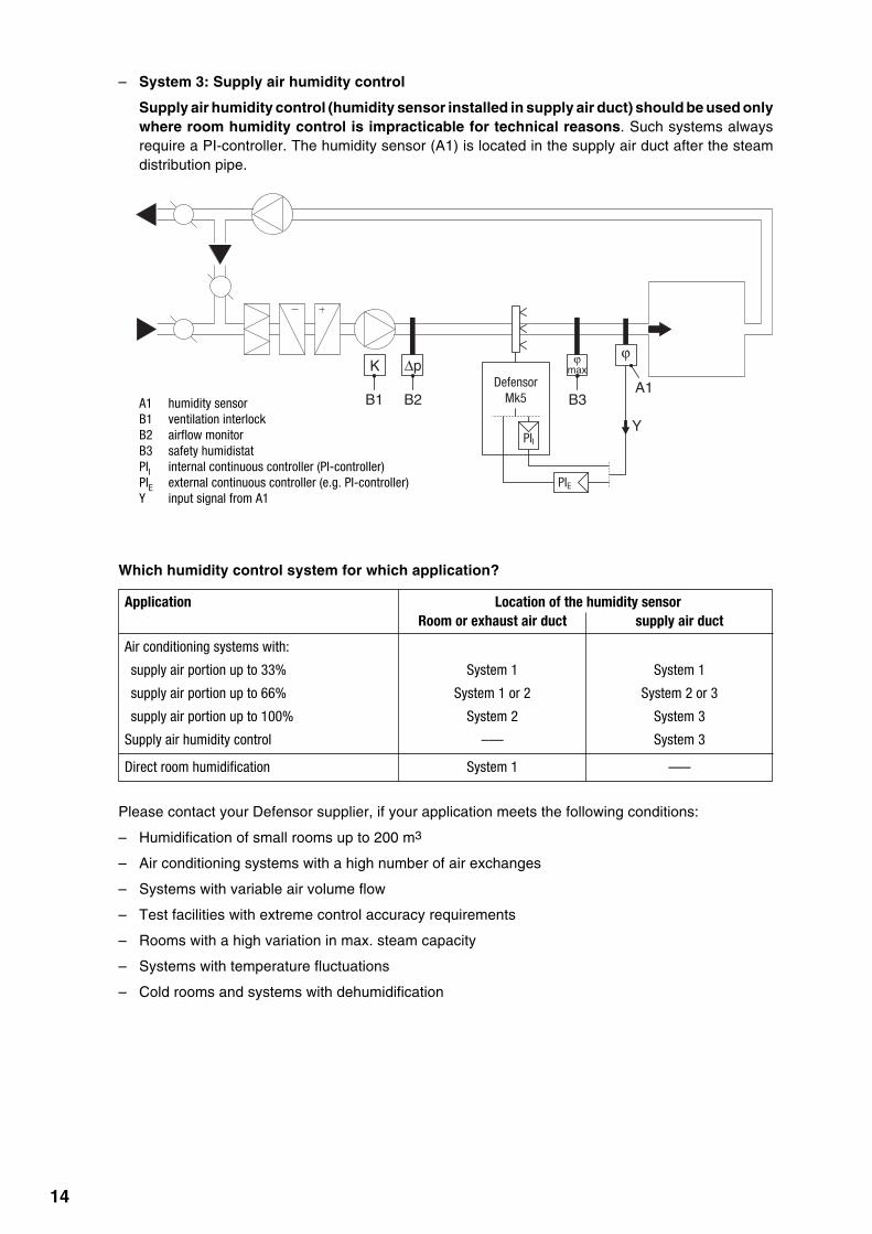
– System 3: Supply air humidity control
Supply air humidity control (humidity sensor installed in supply air duct) should be used onlywhere room humidity control is impracticable for technical reasons. Such systems alwaysrequire a PI-controller. The humidity sensor (A1) is located in the supply air duct after the steamdistribution pipe.
A1 humidity sensorB1 ventilation interlockB2 airflow monitorB3 safety humidistatPII internal continuous controller (PI-controller)PIE external continuous controller (e.g. PI-controller)Y input signal from A1
Which humidity control system for which application?
Application Location of the humidity sensorRoom or exhaust air duct supply air duct
Air conditioning systems with:
supply air portion up to 33% System 1 System 1
supply air portion up to 66% System 1 or 2 System 2 or 3
supply air portion up to 100% System 2 System 3
Supply air humidity control ––– System 3
Direct room humidification System 1 –––
Please contact your Defensor supplier, if your application meets the following conditions:
– Humidification of small rooms up to 200 m3
– Air conditioning systems with a high number of air exchanges
– Systems with variable air volume flow
– Test facilities with extreme control accuracy requirements
– Rooms with a high variation in max. steam capacity
– Systems with temperature fluctuations
– Cold rooms and systems with dehumidification
ϕmax
DefensorMk5
∆pK
B1 B2 B3
ϕ
Y
A1
PIE
PII

15
4.3 Options
The following table presents an overview of all options which are available for the steam humidifierDefensor Mk5.
Defensor Mk5 Visual ProcessSteam capacity in kg/h 5...16 20...40 50...80 5...16 20...40 50…80
Interface RS232/RS485 ––– RS(Interface PCB RS232/RS485 for dataexchange with a building controlsystem)
Remote operating and fault indication RFS(PCB with relay contacts for the connec-tion of remote displays for “Operation”,“Steam”, “Fault” and “Service”)
Pressure compensation kit up to 10’000 Pa OVP(Assembly kit for the installation of thefilling bowl on the equipment cover, forthe operation of the steam humidifier ininstallations with duct air pressures upto 10’000 Pa)
Transformer 450-500V/230V TRAF 1)
(Transformer for systems without a sep-arate control voltage supply)
Connection terminal 400-415 V/3~ KLK KLG KLK KLG(Separate terminals for systems wheredirect connection of heating voltage tomain contactor (standard version) isnot permitted by local regulations)
Unit housing stainless steel S-Inox L-Inox S-Inox L-Inox
1) When ordering indicate the type of unit
number – – – 1 1 1
number 1 1 1 1 1 1
number 1 1 2 1 1 2
number 1 1 1 1 1 1
number 1 1 2 1 1 2
number 1 1 2 1 1 2
16
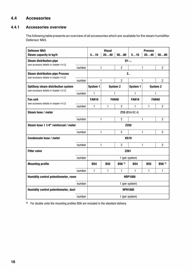
4.4 Accessories
4.4.1 Accessories overview
Defensor Mk5 Visual ProcessSteam capacity in kg/h 5…16 20…40 50…80 5…16 20…40 50…80
Steam distribution pipe 81-...
number 1 2 1 2
Steam distribution pipe Process Z..
number 1 2 1 2
OptiSorp steam distribution system System 1 System 2 System 1 System 2
number 1 1 1 1
Fan unit FAN16 FAN40 FAN16 FAN40
number 1 1 2 1 1 2
Steam hose / meter Z10 (Ø54/42.4)
number 1 2 1 2
Steam hose 1 1/4" reinforced / meter Z250
number 1 2 1 2
Condensate hose / meter KS10
number 1 2 1 2
Filter valve Z261
number 1 (per system)
Mounting profile BS4 BS5 BS6 1) BS4 BS5 BS6 1)
number 1 1 1 1 1 1
Humidity control potentiometer, room HRP1000
number 1 (per system)
Humidity control potentiometer, duct HPH1000
number 1 (per system)
1) For double units the mounting profiles BS6 are included in the standard delivery
The following table presents an overview of all accessories which are available for the steam humidifierDefensor Mk5.
(see accessory details in chapter 4.4.2)
(see accessory details in chapter 4.4.2)
(see accessory details in chapter 4.4.2)
(see accessory details in chapter 4.4.2)

17
Steam distribution pipes 81-... for indirect room humidification
The steam distribution pipes are selected on the basis of the duct width (for horizontal installation) orthe duct height (for vertical installation) and the capacity of the steam humidifier.Important! Always select the longest possible steam distribution pipe (optimum humidification dis-tance).
4.4.2 Accessory details
Steam distribution pipes 81-... Duct width (B) Steam outputfor Defensor Mk5 (CrNi steel)Type Length in mm (L) 3) in mm max. in kg/h
81-200 1) 200 210…400 10
81-350 2) 350 400…600 30
81-500 2) 500 600…750 30
81-650 650 750…900 50
81-800 800 900…1100 50
81-1000 1000 1100…1300 50
81-1200 1200 1300…1600 50
81-1500 1500 1600…2000 50
81-1800 1800 2000…2400 50
81-2000 2000 2200…2600 50
81-2300 2300 2500…2900 50
81-2500 2500 2700…3100 50
1) Only for units with a max. steam capacity of 10 kg/h2) Only for units with a max. steam capacity of 30 kg/h3) Special length available on request
B
L
Note: If the humidification distance (see chapter 5.3.1) has to be reduced for technical reasons, theamount of steam per basic unit must be divided between two steam distribution pipes or the OptiSorpsteam distribution system must be used. If this is the case, contact your Defensor supplier.
Steam distribution pipe “Process” (accessory “Z...”)
The steam distribution pipe “Process” is used for direct humidification of material in manufacturingprocesses (process humidification), or in ventilation ducts with a critical saturation distance (thesteam distribution pipe “Process” reduces the saturation distance by approximately 30%). The desiredlength must be specified when ordering.
Please contact your Defensor distributor, they will assist you in customizing the steam distribution head“Process”. Please have the following information readily available:
– steam quantity in kg/h
– dimensions of ventilation duct (width x height)
Important! The table for the determination of the humidification distance provided in chapter 5.3.1 doesnot apply to the Process steam distribution pipe.

18
OptiSorp steam distribution system
The OptiSorp steam distribution system is used in ventilation ducts where only a short humidificationdistance is available (see chapter 5.3.1 for calculation of humidification distance). Duct dimensionsshould be given when ordering. Please note the following data for this:
OptiSorp Number of max. steam capacity Duct dimensionsteam connections in kg/h 1) Width in mm Height in mm
System 1 1 45 (30) 450...2700 450...1650
System 2 2 90 (60) 450...2700 450...2200
1) For duct width <600 mm the values in parenthesis are valid
Note: Further information on the OptiSorp steam distribution system can be found in the separateTechnical Documentation supplied with the product.
Fan unit
The fan units – in combination with the steam humidifiers Defensor Mk5 Visual – are used for the directroom humidification. They can be mounted separately above the unit to the wall.
The type of fan unit (FAN16 or FAN40) and the amount required is dependent on the steam capacityof the basic unit(s) and can be gathered from the table in chapter 4.4.1.
Note: Further information on the fan unit can be found in the separate Technical Documentationsupplied with the product.
The fan units are delivered with:
– Installation accessories including steam hose
– Technical Documentation Fan unit
B
H

19
4.5 Additional planning instructions
In addition to the selection of the steam humidifier, the accessories and the options, other points shouldbe considered during planning. Please note the information in the following chapters:
– Unit fitting (see chapter 5.2)
– Steam installation (see chapter 5.3)
– Water installation (see chapter 5.4)
– Electric installation (see chapter 5.5)
If you have other questions relating to planning that are not adequately covered by technicaldocumentation, please contact your Defensor representative. He will be happy to provide furtherassistance.
20
5 Mounting and installation works
5.1 Safety instructions for mounting and installation works
– All mounting and installation work must be performed only by adequately qualifiedpersonnel. Ascertaining the qualifications is the customer‘s responsibility.
– All local regulations relating to the execution of the respective installation work (Water,steam and electrical installation) must be noted and complied with.
– All the information contained in this technical documentation relating to equipmentassembly and to water, steam and electrical installation must be unconditionallyobserved and complied with.
– Caution - Danger from electric shock! The connection of the steam humidifier tothe mains electrical supply must not be made until all installation work has beencompleted.
– Electronic components are very sensitive to electrostatic discharges. In order to protectthese components, during all installation work with the equipment opened, precautionsmust be taken against damage due to electrical discharge (ESD protection).
5.2 Unit fitting
5.2.1 Humidifier location
The installation site of the steam humidifier depends largely on the location of the steam distribution pipeor fan unit (see chapter 5.3.1 and 5.3.2), respectively. To ensure proper functioning of the steamhumidifier and to obtain an optimal efficiency, the following points must be considered and observedwhen choosing the location for the steam humidifier:
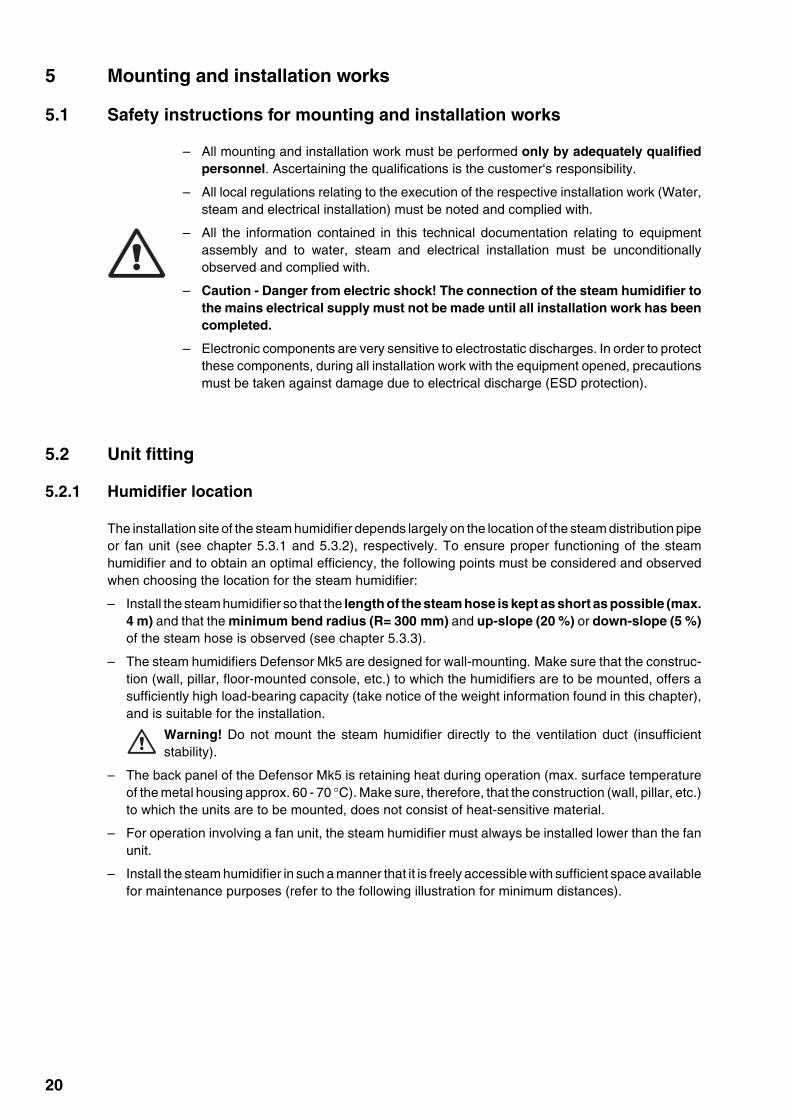
– Install the steam humidifier so that the length of the steam hose is kept as short as possible (max.4 m) and that the minimum bend radius (R= 300 mm) and up-slope (20 %) or down-slope (5 %)of the steam hose is observed (see chapter 5.3.3).
– The steam humidifiers Defensor Mk5 are designed for wall-mounting. Make sure that the construc-tion (wall, pillar, floor-mounted console, etc.) to which the humidifiers are to be mounted, offers asufficiently high load-bearing capacity (take notice of the weight information found in this chapter),and is suitable for the installation.
Warning! Do not mount the steam humidifier directly to the ventilation duct (insufficientstability).
– The back panel of the Defensor Mk5 is retaining heat during operation (max. surface temperatureof the metal housing approx. 60 - 70 °C). Make sure, therefore, that the construction (wall, pillar, etc.)to which the units are to be mounted, does not consist of heat-sensitive material.
– For operation involving a fan unit, the steam humidifier must always be installed lower than the fanunit.
– Install the steam humidifier in such a manner that it is freely accessible with sufficient space availablefor maintenance purposes (refer to the following illustration for minimum distances).

21
Dimensions and Weights
Housing size small large Double unit large
Steam capacity 5 8 10 16 20 24 30 40 50 60 80in kg/h
Netweight 36 36 37 38 41 43 43 44 1x41 2x43 2x44 in kg 1x43
Grossweight 51 51 52 53 71 73 73 74 1x71 2x73 2x74 in kg 1x73
min
. 400
mm
min. 600 mm
min
. 600
mm
min
. 600
mm
50 mm
min. 400 mmmin. 50 mm
Unit AUnit B
Mk5 ... 50 ... Mk5 ... 60 ... Mk5 ... 80 ...20 kg/h 30 kg/h 40 kg/h30 kg/h 30 kg/h 40 kg/h
Unit A:Unit B:
437 mm 500 mm
1087
mm
1087
mm
392 mm 594 mm
160 mm257 mm 194 mm212 mm
300
mm
300
mm
69 mm 132 mm 103 mm45 mm
Minimum distances to observe

22
5.2.2 Mounting the humidifier
• Use the drilling template (printed on the packing) to mark attachment point “A” on the wall.Important! Observe location notes.
• Drill hole ø10 mm, insert the supplied plastic plug, and tighten the screw until the distance betweenthe wall and the screw head is 5 mm.
• Unlock left front panel and remove both front panels. Hang up the unit on the screw, and use the spiritlevel to adjust it horizontally and vertically.
• Mark attachment points “B”. When finished, remove the unit again.
• Drill holes ø10 mm and insert the supplied plastic plugs.
• Hang the unit up on the screw again before attaching it with the remaining two screws. Beforetightening the screws, readjust the unit with the spirit level.
• Reattach the front panels and lock them.
5.2.3 Inspecting the installed unit
Use the following check list to ascertain that the installation was performed correctly:
Is/are the unit(s) in the correct place?(see chapter 5.2.1)
Is/are the unit(s) correctly aligned vertically and horizontally?
Is steam humidifier properly secured?(stability of the carrying structure)
Caution! When fixing the Defensor Mk5, use only the fixing materials supplied with theunit. If fixing with the materials supplied is not possible in your particular case, select amethod of fixing that is of similar stability. In case of doubt, please contact your Defensorsupplier.
Note: The following explains how to fix the unit without optional mounting profiles. To install the unit withmounting profiles, please note the special instructions printed on the packaging.
ca
d
b
A
B
Measure Housingsmall large
a 232.0 mm 237.0 mmb 175.0 mm 181.0 mmc 166.0 mm 166.0 mmd 460.0 mm 460.0 mm

23
5.3 Steam installation
5.3.1 Positioning and mounting of the steam distribution pipes
The location for the steam distribution pipes should be determined at the time of dimensioning the airconditioning system. Please note the following instructions to ensure proper humidification of the ductair.
Calculating the humidification distance
The water vapour, emitting from the steam distribution pipes, requires a certain distance to be absorbedby the ambient air so that it is no longer visible as steam. This distance is referred to as humidificationdistance “BN” and serves as a basis for the determination of the minimum distances from the upstreamcomponents in the system.
The calculation of the humidification distance “BN” is dependent on several factors. For a roughestimation of the humidification distance “BN”, the following table is useful. Recommended standardvalues listed in this table are based on a supply-air temperature range of 15°C to 30°C. The values givenin bold type only apply to steam distribution pipes 81-..., the values in brackets apply to theOptiSorp steam distribution system.
Humidification distance BN in mHumidity at inlet Humidity at outlet
ϕ1 in %rh ϕ2 in %rh40 50 60 70 80 90
5 0.9 (0.22) 1.1 (0.28) 1.4 (0.36) 1.8 (0.48) 2.3 (0.66) 3.5 (1.08)10 0.8 (0.20) 1.0 (0.26) 1.3 (0.34) 1.7 (0.45) 2.2 (0.64) 3.4 (1.04)20 0.7 (0.16) 0.9 (0.22) 1.2 (0.30) 1.5 (0.41) 2.1 (0.58) 3.2 (0.96)30 0.5 (0.10) 0.8 (0.17) 1.0 (0.25) 1.4 (0.36) 1.9 (0.52) 2.9 (0.88)40 – 0.5 (0.11) 0.8 (0.20) 1.2 (0.30) 1.7 (0.45) 2.7 (0.79)50 – – 0.5 (0.13) 1.0 (0.24) 1.5 (0.38) 2.4 (0.69)60 – – – 0.7 (0.16) 1.2 (0.30) 2.1 (0.58)70 – – – – 0.8 (0.20) 1.7 (0.45)
For duct widths <600 mm the humidification distance for the OptiSorp system increases by approx. 50%
ϕ1 in %rh: Relative supply air humidity prior to humidification at the lowest supply air temperatureϕ2 in %rh: Relative supply air humidity after the steam distribution pipe at maximum capacity
Example
given: ϕ1= 30 %rh, ϕ2= 70 %rh
humidification distance BN: 1,4 m (0.36 m for OptiSorp steam distribution system)
Note: If the humidification distance has to be reduced for technical reasons, the amount of steam perbasic unit must be divided between two steam distribution pipes or the OptiSorp steam distributionsystem must be used. If this is the case, contact your Defensor supplier.
ϕ1 ϕ2
1 x BN 4-5 x BN
Humidificationdistance BN Expansion- and mixing zone
ϕ1: Incoming air humidity before humidificationϕ2: Air humidity after humidification

24
Minimum distances to be observed
To prevent the water vapour, that is emitting from the steam distribution pipe, from condensing ondownstream system components, a minimum distance to the steam distribution pipe must be observed(depends on the humidification distance “BN”).
0,5 x BN BN0,5 x BN
before/after filter/register before/after fan, zone exit
Installation notes and dimensions
The steam distribution pipes are designed for either horizontal installation (on the duct wall) or, withaccessories, for vertical installation (in the duct floor). The outlet orifices should always pointupwards and at right angles to the airflow.
If possible, the steam distribution pipes should be installed on the pressure side of the duct (max. ductpressure 1500 Pa). If the steam distribution pipes are installed on the suction side of the duct, themaximum vacuum must not exceed 1000 Pa.
Select a location for the installation, tailored to suit your duct (see the following illustrations) and positionthe steam distribution pipes in the duct so that a uniform distribution of steam is achieved.
BN BN 5 x BN
1,5 x BN 5 cm BN BN
before/after constriction after expansion before bend
before branch before diffuser before control sensor
2,5 x BN before submicron particle filter

25
In positioning the steam distribution pipes, the following dimensions should be observed.
Note: Please note the instructions in the separate documentation for this product when locating theOptiSorp steam distribution system.
Guidelines for dimensioning the ventilation ducts
– To facilitate the installation of the steam distribution pipes and for control purposes, a sufficientlysized control opening should be planned.
– Within the range of the humidification distance, the ventilation duct should be water-proofed.
– Air ducts passing through cold rooms should be insulated to prevent the humidified air fromcondensing along the duct wall.
– Poor airflow conditions within the air duct (e.g. caused by obstacles, tight bends, etc.) can lead tocondensation of the humidified air.
– Steam distribution pipes must not be mounted to round ducts.
If you have questions relating to the dimensioning of ventilation ducts in combination with steamhumidifiers, contact your Defensor supplier.
Installing the steam pipes/the OptiSorp steam distribution system
Detailed information on the installation of steam distribution pipes/OptiSorp steam distribution systemcan be found in the separate “Mounting Instructions” for this products.
1/2 H1/2
H
H
1/3
2/3H
1/5
1/5
2/5
1/5
H
2/72/7
3/7
1/51/5
H
2/5
1/5
1/4 H1/41/41/4
1/3 H1/31/3
2/7
2/7
3/7
H
1/21/2
1/5H
1/51/51/51/5
H
1/61/6
2/6
1/61/6
H
1/6
1/6
2/6
1/61/6
min H= 250 mm min H= 200 mm
min H= 300 mm
min H= 400 mmmin H= 500 mm
min H= 350 mmmin H= 400 mm
min H= 600 mm
hmin
gmin gmin
gmin
min H= 500 mmmin H= 600 mmmin H= 720 mm
gmin gmin
gmin
H ≥400 mm
fmin= 150 mmgmin= 100 mmhmin= 85 mm

26
The fan unit is mounted on the wall separately above the unit. To allow the steam coming from thefan unit to spread out evenly, without condensing on obstacles (ceilings, joists, pillars, etc.), the followingminimum dimensions must be observed when selecting the location for the fan unit.
FAN16 FAN40
mD max. 8 kg/h 16 kg/h 30 kg/h 40 kg/h
A min. 3.0 m 6.0 m 8.0 m 10.0 m
B min. 0.5 m 0.7 m 1.0 m 1.5 m
C ca. 2.2 m 2.2 m 2.2 m 2.2 m
D ca. 0.5 m 0.7 m 1.0 m 1.5 m
E 0.15 ... 2.0 m 0.2 ... 2.0 m 0.3 ... 2.0 m 0.5 ... 2.0 m
Note: The minimum spaces in the table apply for a room atmosphere of 15 °C and max. 60 %rh. For lower temperaturesand/or higher humidity the values must be increased accordingly
Note: In order to achieve a uniform distribution of the humidity within the room, additional factors suchas the room size, the room height, etc., must be taken into consideration besides observing the minimumdistances. If you have questions concerning the direct room humidification, please contact yourDefensor supplier.
Further information is provided in the separate “Technical documentation for the fan unit”.
5.3.2 Positioning and mounting of the fan unit
E
A
C
B
D
D

27
Important! Use original Defensor steam hose exclusively. Other types of steam hoses can causeundesired operational malfunctions.
Instructions for the hose layout
The hose layout depends on the position of the steam distribution pipe:
– Steam distribution pipe is mounted more than 300 mm above the top edge of the humidifier:
Initially, lead the steam hose with an upslope of at least 20% over a minimum height of 300 mm,then lead the hose with a minimum upslope of 20% and/or a minimum downslope of 5% to thesteam distribution pipe.
Note: For steam capacities ≤20 kg/h the separate return of the condensate via the condensationhose can be dispensed with. The special instructions for hose positioning in the “Steam distributionpipe installation instructions 81-…” should be noted.
– Steam distribution pipe is mounted less than 300 mm above the top edge of the humidifier:
Initially, the steam hose is led with an upslope of at least 20 % over a minimum height of 300 mmabove the top edge of the humidifier and then down to the steam distribution pipe with a minimumslope of 5 %.
– The steam hose should be kept as short as possible (max. 4 m) while observing the minimum bendradius of 300 mm. Important! Allowance must be made for a pressure loss of 10 mm watercolumn (approx. 100 Pa) per meter steam hose.
– Reductions in the cross section such as kinks should be avoided throughout the entire length of thehose. The installation of a stop cock in the steam hose is not permissible.
5.3.3 Installing the steam hose
min
. 300
mm
Rmin
.30
0 m
m
min. 5 % min. 20 %
max
. 4 m
min
. 300
mm
min. 20 %
Rmin.
300 mm
max
. 4 m
Rmin
.30
0 m
m
min. 20 %min. 5 %
min
. 300
mm
max
. 4 m
Rmin
.
300
mm
min. 20 %min. 5 %
min. 20 % min
. 300
mm
max
. 4 m
28
– Steam hoses must be prevented from sagging (condensate pockets); if necessary, support with pipeclamps, trough, or wall brackets, or install a condensate drain in the steam hose.
– Important! When deciding on the length and layout of the hose, it should be noted that the steamhose may become somewhat shorter with progressive ageing.
Securing the hose
The steam hose must be secured to the steam distribution pipe and humidifier steam outlet by meansof hose clamps.
Steam line with fixed piping
For steam lines with fixed piping, the same instructions apply to the laying of the piping as alreadydescribed. The following additional notes should be observed:
– The minimum internal diameter of 45 mm should be applied over the whole length of the piping.
– Use exclusively Cu pipe (operation with untreated water) or stainless steel (min. DIN 1.4301,operation with fully demineralized water).
– To minimize the condensate formation (=loss), the steam pipes must be insulated.
– The minimum bend radius for rigid piping is 100 mm.
– Connection of the steam pipes to the steam distribution pipe and steam humidifier is effected bymeans of short lengths of steam hose secured with hose clamps. Connection to the steam humidifieris secured via a G 1 1/4” coupling.
– Important! Allowance must be made for a pressure loss of 10 mm water column (approx.100 Pa) per meter line length or per 90° angle.
5.3.4 Installing the condensate hose
Important! Use original Defensor condensate hose exclusively. Other types of hoses can causeoperational malfunctions.
The hose layout depends on the position of the steam distribution pipe:
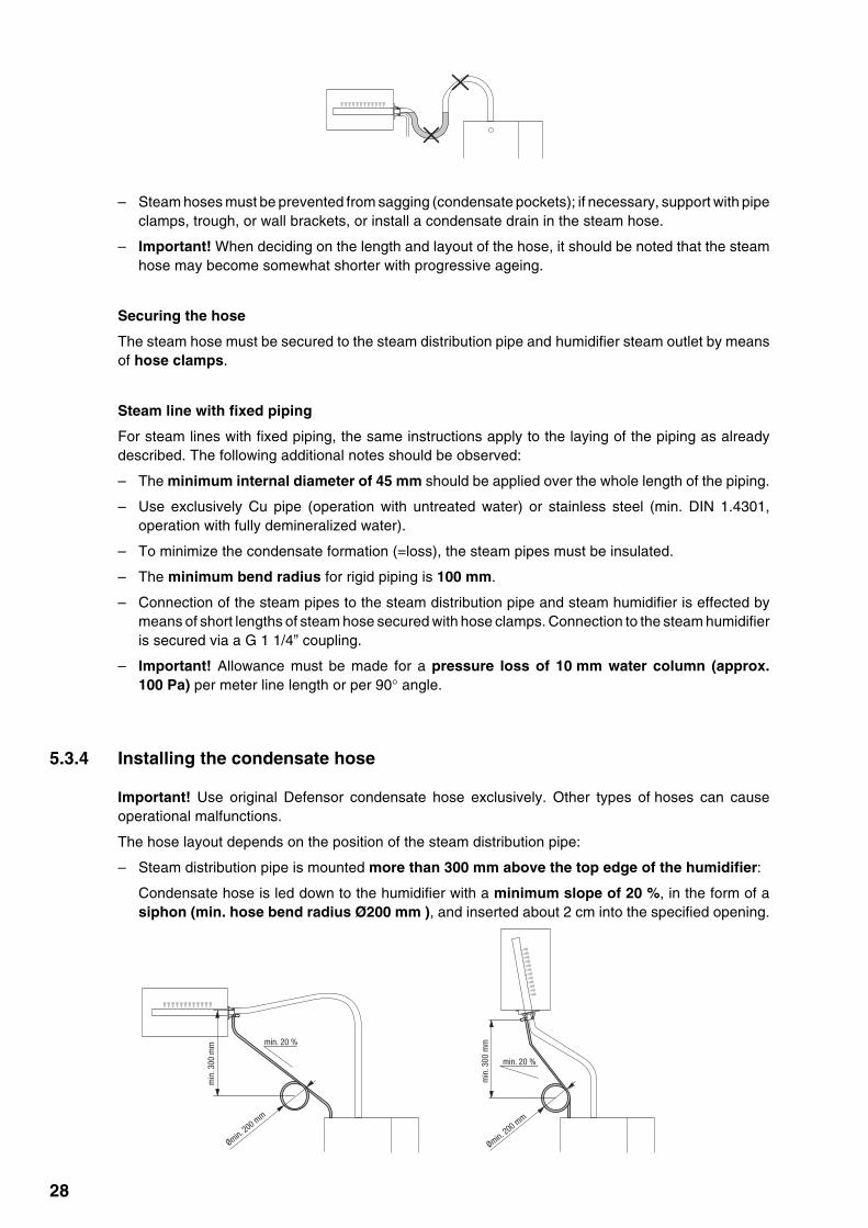
– Steam distribution pipe is mounted more than 300 mm above the top edge of the humidifier:
Condensate hose is led down to the humidifier with a minimum slope of 20 %, in the form of asiphon (min. hose bend radius Ø200 mm ), and inserted about 2 cm into the specified opening.
min
. 300
mm
min
. 300
mm
min. 20 %
Ømin. 200 m
m
Ømin. 200 m
m
min. 20 %

29
– Steam distribution pipe is mounted less than 300 mm above the top edge of the humidifier:
Condensate hose is led down with a minimum slope of 20 %, in the form of a siphon (min. hosebend radius Ø200 mm), directly into a discharge funnel.
Note: If your unit feeds a number of steam distribution pipes, the individual condensate hoses are tobe led into the discharge funnel.
Important! Before putting the unit into operation, the siphon of the condensate hose must be filled withwater.
5.3.5 Inspecting the steam installation
Use the following check list to ascertain that the steam installation was performed correctly:
– Steam distribution pipe
Steam distribution pipe correctly positioned and secured (screws tightened)?
Are the outlet orifices at right angles to the air flow direction?
– Steam hose
Maximum length of 4 m?
Minimum bend radius of 300 mm (100 mm with fixed piping)?
Have the instructions for hose positioning been followed?
Steam hose: no sagging (condensate pocket)?
Rigid steam lines: properly insulated? Correct installation material used? Minimal internaldiameter maintained?
Steam hose securely attached with clamps?
Heat expansion during operation and shortening of the hose with ageing taken into consider-ation?
– Condensate hose
Downslope of at least 20 %?
Siphon existing and filled with water?
Condensate hose correctly fixed?
min. 20 %
min
. 300
mm
min. 20 %
min
. 300
mm
Ømin.
200
mm
Ømin.
200
mm

30
5.4 Water installation
All work concerning the water installation must be performed only by adequately qualifiedpersonnel (e.g. plumbers). Ascertaining the qualifications is the customer‘s responsibility.
Please observe all local regulations concerning the installation of appliances to themains and waste water systems.
Warning - danger of electric shock! For all installation work, the steam humidifier mustbe disconnected from the mains supply and secured against unintentional re-connection.
5.4.1 Performing the water installation
Overview water installation
1 Water connection, union nut G 1/2"2 Water supply pipe (min. inner Ø: 8 mm)3 Water drain Ø40 mm4 Drain pipe (min. inner Ø: 40 mm, min. 30 cm directed vertically downwards)5 Pressure reducing valve (compulsory for water pressures >10 bar, building side)6 Manometer (installation recommended, building side)7 Filter valve (accessory “Z261”)8 Funnel (building side)9 Siphon (min. inner Ø: 40 mm, building side)
10 Drain line, building side (min. inner Ø: 40 mm)
H2O(1…10 bar)
min
. 30
cm
1
3
2
4
567
8 9 10

31
Water supply
The water feed pipe (min. internal Ø: 8 mm) is to be connected via the filter valve that is available asan accessory, to the connection on the unit (see detailed illustration). Alternatively, a shut-off valve anda water filter may be installed. The installation of the filter valve should be made as close as possibleto the steam humidifier.
Warning - danger of damage! Union nut at the humidifier connection must be hand-tightenedonly.
The following connection specifications must be observed:
– Connection on unit: G 1/2" (Union nut)
– Min. inner Ø of supply line: 8 mm
– Admissible mains pressure 1.0 to 10.0 bar (hammer-free system)For mains pressures >10 bar, connection must be made via pressure reducing valve (adjusted to2.0 bar). For mains pressures <1.0 bar please contact your Defensor supplier.
– Admissible supply temperature: 1…40 °C– The connection material must be pressure-proof and certified for use in the drinking water supply.
Warning! Fully demineralized water is aggressive. The connections for a demineralizedwater system should be made exclusively from stainless steel (min. DIN 1.4301) orchemically resistant plastics (e.g. polypropylene).
– Important! Before connecting the water line, the line should be well flushed out.
– Water quality: For the water supply, use exclusively fresh tap water (raw water), partially softenedwater or fully demineralized water (conductivity <15 µS) without additives (e.g. Chlorine,disinfectant agents, ozone, etc.), with a max. 1000 germs/ml.Note: Softened water can lead to operating failures, since it has a tendency to foam during operation.
For more ample information on water quality please contact your Defensor supplier.
Water drain
The water drainage is effected without pressure. Thus, in order to avoid any damming of the water, thedrain pipe must be led straight down into a drainage funnel, through a piece of hose with a min.length of 30 cm. Subsequently, the drain pipe is connected via siphon to the waste water system ofthe building. The minimum inside diameter of 40 mm must be observed over the whole length of the drainpipe. Make certain that the drain pipe is correctly fixed and easily accessible for inspections and cleaningpurposes.
The following connection specifications must be observed:
– Drainage capacity: approx. 2,5l/min per 15 kg/h steam capacity
– Drainage temperature: 60…100 °CWarning! Use only temperature-resistant installation materials!Warning! Fully demineralized water is aggressive. The connections for a demineralizedwater system should be made exclusively from stainless steel (min. DIN 1.4301) orchemically resistant plastics (e.g. polypropylene).
– Connection on unit: hose connection Ø40 mm
Warning! Hose must be secured to the unit connection with a hose clamp.
– Min. inner Ø of drain line: 40 mm
– Min. downslope after siphon: 10 %

32
5.4.2 Inspecting the water installation
Use the following check list to ascertain that the installation has been performed correctly:
– Water supply
Has filter valve or shut-off valve and filter 5 µm respectively been installed in supply line?
Have admissible water pressure (1.0 – 10 bar) and temperature (1 – 40 °C) been observed?
Does supply capacity match the humidifier(s)?
Are all pipes properly secured (threaded connections tightened)?
Is the feed pipe properly sealed?
– Water drain
Has minimum inside diameter of drain pipes been maintained at least 40 mm throughout theentire length?
Has drain pipe been installed with a downslope of at least 10 %?
Has the heat resistance of the material used been verified to be at least 100°C?
Are hoses and lines properly secured (hose clamps and threaded connections tightened)?

33
1
2
Uc
UpQ3F3
6
7
9
Q4F4
ϕmax∆pK
11
8
10
DefensorMk5(A)
ϕ
ϕ
ϕ
P/I
P/I
1314
3
4
5
1215
DefensorMk5(B)
5.5 Electric installation
– All work concerning the electric installation must be performed only by adequatelyqualified personnel (electrician or workman with equivalent training). Ascertain-ing the qualifications is the customer‘s responsibility.
– Warning - danger of electric shock! The steam humidifier may be connected toelectric mains only after all installation work has been completed.
– Please observe all local regulations concerning the electric installation.
– Warning! Electronic components inside the unit are very susceptible to electrostaticdischarges. For the protection of these components, measures must be taken duringall installation work to prevent damage caused by electrostatic discharge (ESD–protection)
5.5.1 Electric installation overview
1 Supply heating voltage Up2 Supply control voltage Uc3 Interface RS232/RS485
(option “RS” for Mk5 Process only)4 Remote operating and fault indications (option “RFS”)5 External continuous controller6 Humidity sensor (supply air/room/exhaust)7 Safety humidistat
8 Airflow monitor9 Ventilation interlock
10 External safety circuit11 Steam humidifier12 Internal continuous controller13 Control voltage supply to second unit14 Control line to second unit15 Second unit (from 50 kg/h)

34
The electrical installation is to be carried out in accordance with the following wiring diagram.
Caution! Observe the installation notes in the following section.
5.5.2 Wiring diagram
F1 (6
.3AT
)
L1
X1X6
F5(5
0mAF
)
1
ONS4
S1 S2 S3
5V
JP2
V+
A1+
A214
0...1
0kΩ
200-
240V
/ 50
... 6
0Hz
L1
F4K3
A3ON
-OFF
K1 Stea
mEr
ror
Serv
ice
Unit
ONK2
K3K4
Q4
L1
F4
Q4
INPU
T 44
0-50
0V
42
3
GND
IN24
V
–
L2NSK
1SK
2
F2 (1
AF)
L1
Q3
PE
F3
K1
L2L3
L1L2
L3
J
PE
N
J3J6
PN
P1
J7
Com
-Por
t
JP1
JP2
12
34
56
78
910
ϕ max
.
∆pB2 B1B3
NL1
P / P
I
V+GN
DIN
V+GN
DIN
F1 (6
.3AT
)
L1
X1X6
NSK
1SK
2
F2 (1
AF)
PN
P1
JP1
JP2
L1
Q3
PE
F3
K1
L2L3
L1L2
L3
M
Cont
rol b
oard
Supp
ly m
odul
e
Unit
AUn
it B
set J
P2to
5V
set J
P2to
24V
Supp
ly m
odul
e
H1 (O
ptio
n)
T1 (O
ptio
n)
Unit
B
Unit
A
35
Legend to wiring diagram
A1 Controller (active) or humidity sensor
A2 Controller (passive), set jumper JP2 to 5V
A3 On/Off control, set jumper JP2 to 24V
B1 Ventilation interlock
B2 Airflow monitor
B3 Safety humidistat
F1 Internal fuse supply module (6.3 A, slow acting)
F2 Internal fuse supply module (1 A, quick acting)
F3 External fuse heating voltage supply (see table in the following chapter)
F4 External fuse control voltage (max. 10 A, slow acting)
F5 Internal fuse control module (50 mA, quick acting)
H1 Remote operating and fault indication (option “RFS”)
J Short circuited, if no external monitoring devices are connected
J3 Connection terminal for remote operating and fault indication
J6 Connection terminal for control line to unit B
J7 Connection terminal for control line from unit A
JP2 Jumper (control signal) on control board unit A
K1 Mains contactor (heating voltage) unit A/unit B
K3 External safety circuit (safety humidistat, airflow monitor, etc.)
M Fan unit (accessory “FAN..”)
Q3 External main switch heating voltage supply
Q4 External main switch control voltage supply
T1 Auto-transformer control voltage supply (option “TRAF”)
S1 Rotary switch "drain interval”
S2 Rotary switch “maintenance interval”
S3 Rotary switch “control signal”
S4 DIP-switch “unit settings”
X1 Connection terminal for control voltage to supply module
X6 Connection terminal for voltage supply from unit A to unit B
36
5.5.3 Notes on component installation
Important note:
– All connecting cables in the electrical installation are to be fed in via the cable glands on the baseof the unit (the exception to this is the heating voltage connection cable, for which the special clampis provided).
– The details relating to individual components are to be noted and followed.
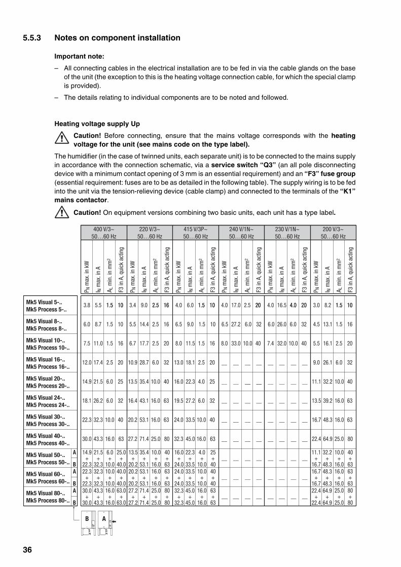
Heating voltage supply Up
Caution! Before connecting, ensure that the mains voltage corresponds with the heatingvoltage for the unit (see mains code on the type label).
The humidifier (in the case of twinned units, each separate unit) is to be connected to the mains supplyin accordance with the connection schematic, via a service switch “Q3” (an all pole disconnectingdevice with a minimum contact opening of 3 mm is an essential requirement) and an “F3” fuse group(essential requirement: fuses are to be as detailed in the following table). The supply wiring is to be fedinto the unit via the tension-relieving device (cable clamp) and connected to the terminals of the “K1”mains contactor.
Caution! On equipment versions combining two basic units, each unit has a type label.
Mk5 Visual 5-..Mk5 Process 5-..
Mk5 Visual 8-..Mk5 Process 8-..
Mk5 Visual 10-..Mk5 Process 10-..
Mk5 Visual 16-..Mk5 Process 16-..
Mk5 Visual 20-..Mk5 Process 20-..
Mk5 Visual 24-..Mk5 Process 24-..
Mk5 Visual 30-..Mk5 Process 30-..
Mk5 Visual 40-..Mk5 Process 40-..
3.8 5.5 3.4 9.0 4.0 6.0 4.0 17.0 4.0 16.5 3.0 8.2
6.0 8.7 5.5 14.4 6.5 9.0 6.5 27.2 4.5 13.1
7.5 11.0 6.7 17.7 8.0 11.5 8.0 33.0 7.4 32.0 5.5 16.1
12.0 17.4 10.9 28.7 13.0 18.1 9.0 26.1
6.0 26.0
__ __ __ __
__ __ __ __
__ __ __ __
__ __ __ __
__ __ __ __
__ __ __ __
__ __ __ __
__ __ __ __
14.9 21.5 13.5 35.4 16.0 22.3 11.1 32.2
18.1 26.2 16.4 43.1 19.5 27.2 13.5 39.2
22.3 32.3 20.2 53.1 24.0 33.5 16.7 48.3
30.0 43.3 27.2 71.4 32.3 45.0 22.4 64.9
71.4+
71.4
27.2+
27.2
43.3+
43.3
30.0+
30.0
53.1+
53.1
20.2+
20.2
32.3+
32.3
22.3+
22.3
35.4+
53.1
13.5+
20.2
21.5+
32.3
14.9+
22.3
45.0+
45.0
32.3+
32.3
33.5+
33.5
24.0+
24.0
22.3+
33.5
16.0+
24.0
64.9+
64.9
22.4+
22.4
48.3+
48.3
16.7+
16.7
32.2+
48.3
11.1+
16.7
Mk5 Visual 50-..Mk5 Process 50-..
Mk5 Visual 60-..Mk5 Process 60-..
Mk5 Visual 80-..Mk5 Process 80-..
1.5 10 2.5 16 1.5 10 2.5 20 4.0 20 1.5 101.5 10 2.5 16 1.5 10 20 4.0 20 1.5 10
1.5 10 2.5 16 6.0 32 1.5 16
1.5 16 2.5 20 1.5 16 10.0 40 10.0 40 2.5 20
2.5 20 6.0 32 6.0 32
__ __
__ __
1.5 10 6.0 32
6.0 25 10.0 40 10.0 40__ __
__ __
__ __
__ __
__ __2.5 20
__ __4.0 25
__ __
__ __
__ __
6.0 32 16.0 63 16.0 636.0 32
16.0 63 16.0 6310.0 40 10.0 40
__ __ __ __
__ __ __ __
__ __ __ __
16.0 63 25.0 80 16.0 63 25.0 80
40+63
10.0+
16.0
25.0+
40.0
6.0+
10.0
25+40
4.0+
10.0
40+63
10.0+
16.063+63
16.0+
16.0
40.0+
40.0
10.0+
10.0
40+40
10.0+
10.0
63+63
16.0+
16.080+80
25.0+
25.0
63.0+
63.0
16.0+
16.0
63+63
16.0+
16.0
80+80
25.0+
25.0
A
B
A
B
A
B
AB
400 V/3~50…60 Hz
220 V/3~50…60 Hz
415 V/3P~50…60 Hz
240 V/1N~50…60 Hz
230 V/1N~50…60 Hz
200 V/3~50…60 Hz
P N m
ax. i
n kW
I N m
ax. i
n A
A L m
in. i
n m
m2
F3 in
A, q
uick
act
ing
P N m
ax. i
n kW
I N m
ax. i
n A
A L m
in. i
n m
m2
F3 in
A, q
uick
act
ing
P N m
ax. i
n kW
I N m
ax. i
n A
A L m
in. i
n m
m2
F3 in
A, q
uick
act
ing
P N m
ax. i
n kW
I N m
ax. i
n A
A L m
in. i
n m
m2
F3 in
A, q
uick
act
ing
P N m
ax. i
n kW
I N m
ax. i
n A
A L m
in. i
n m
m2
F3 in
A, q
uick
act
ing
P N m
ax. i
n kW
I N m
ax. i
n A
A L m
in. i
n m
m2
F3 in
A, q
uick
act
ing

37
Control voltage supply Uc
Caution! Before connecting, make sure that the mains voltage corresponds with the controlvoltage of the unit (200…240 V, 50…60 Hz).
Caution! The humidifier must only be connected to a mains supply with a protective conductor.
The connection to the control voltage Uc is made in accordance with the connection schematic, to theterminal “X1” on the supply module. The customer is to install a service switch Q4 in the supply line(all pole disconnecting device with a minimum contact opening of 3 mm) and an F4 fuse (max. 10 Aslow acting) (these are both essential requirements).Note: On versions in which two units are incorporated, the control voltage connection is made to the unitfitted with the display and operating facility (unit A). The terminal “X1” of the second unit (unit B) remainsunused. To supply the control voltage to unit B, the terminals “X6” on the supply modules of both unitsmust be connected using the supplied cable.
The cross-section of the mains cable must comply with the applicable local regulations (minimum of1.5 mm2).
External safety circuit
To ensure the safety of the humidifier system, it is essential that a so-called external safety circuit beprovided to monitor the operation.
To this end, the potential-free contacts (max. contact loading 250V/5A) of the external monitoringdevices (e.g. maximum humidistat, flow monitor, ventilation interlock, etc.) are connected in series withthe corresponding contacts on the terminal “X1”, in accordance with the connection schematic.
Caution, danger of electric shock! The mains voltage is connected to terminal “X1” (up to240 V). The steam humidifier must therefore be isolated from the mains supply (power and controlcomponents), before starting the connection work.
If, for whatever reason, no external monitoring devices are connected, a connecting bridge “J” must beinstalled on the appropriate contacts on the terminal strip “X1”.
Do not apply any extraneous voltage to the terminals.
The cross-section of the cable must comply with the applicable local regulations (minimum of 1 mm2).
Remote operating and fault indication H1 (Option “RFS”)
The optional remote operating and fault indication PCB is to be connected via the connection socket“J3” on the control board. The remote operating and fault indication PCB contains the potential-free relaycontacts K1… K4 for the connection of the following operating and fault indications:
– K1 “Steam production”: This relay closes as soon as the unit produces steam.
– K2 “Fault”: This relay is activated if there is a fault.
– K3 “Maintenance”: This relay is activated when the set service interval has expired.
– K4 “Unit On”: This relay closes as soon as the unit is switched on via the main switch.
The maximum contact loading is 250V/5A.
Appropriate suppressor modules are to be used for the switching of relays and miniature contactors.

38
Control signal / Humidity sensor signal
The connection of an external active controller “A1”, a passive controller “A2”, an On/Off Humidistat “A3”or a humidity sensor (for control via the internal controller), is accomplished on the appropriate contactson the terminal strip in accordance with the connection schematic. Note the following connectioninformation:
Controllerextern intern
Connection active controller passive controller On/Off controller Humidity sensor“A1” “A2” “A3”
Pos. Jumper JP2
– neutral X X
– 5V 140 Ω…10 kΩ
– 24V X
Rotary switch S3
Pos. Signal
0 No signal selected1 On/Off 24V X2 0…5 VDC (Potentiometer) X3 0…10 VDC X X4 0…1 VDC X X5 1…5 VDC X X6 2…10 VDC X X7 0…20 V Phase intersect X X8 4…20 mA X X9 0…20 mA X X
Note: The controller humidity sensor is to be mounted at a suitable position in the duct after the steamdistribution pipe, with a minimum separation of 5 times the humidification distance BN (but not close tothe heating or cooling units of the ventilation system).Please refer to the separate installation instructions for the controller/sensor when positioning andconnecting these components.
Control cable for versions with two units
The supplied control cable (flat ribbon cable) is connected to terminal “J6” on the control board of unit Aand to terminal “J7” on the supply module of unit B.
Connecting the fan unit
See separate documentation “Fan unit”
RS232/RS485 connection
See separate documentation “Interface RS232/485”
24V 5V
JP2
24V 5V
JP2
24V 5V
JP2

39
5.5.4 Inspecting the electrical installation
Inspect for correct installation in accordance with the following checklist:
Do the mains voltages applied correspond to the respective details stated on the rating plate/s forthe power and control components?
Are the voltage supplies (Power and control components) correctly fused?
Is the service switch “Q” installed in the supply cable to the power and control components?
Are all components correctly connected in accordance with the connection schematic?
Are all connection cables fixed?
Are the connecting cables free of tension (fitted through cable glands/secured with cable clamps?)
Is the rotary switch “S3” set to correspond with the controller (active, passive, On/Off) or humiditysensor?
Is jumper “JP2” on the control board correctly set for the controller used?

40
6 Operation
6.1 Unit configuration
Warning - danger of electric shock! Disconnect the steam humidifier from the mainssupply (heating and control voltage) before opening the unit.
Warning! Electronic components inside the unit are very susceptible to electrostaticdischarges. For the protection of these components, measures must be taken during allinstallation work to prevent damage caused by electrostatic discharge (ESD–protection).
All adjusting elements are situated on the control board:
– Rotary switch “S1”: drain interval
– Rotary switch “S2”: maintenance interval
– Rotary switch “S3”: control signal (see chapter 5.5.3)
– Rotary switch “S4”: unit settings
Setting the drain interval (“S1”)
The evaporation process increases the concentration of mineral salts in the steam cylinder. Periodicflushing followed by refilling of fresh water can keep the concentration of mineral salts at a low level.
The interval time to be selected depends on the quality of the water and the type of unit. It may haveto be adapted to the actual circumstances during operation. The following maintenance intervals canbe selected.
Position drain interval Unit type Defensor Mk5 Visual/Process“S1” at 100% steam capacity 5-.. 8-.. 10-.. 16-.. 20-.. 24-.. 30-.. 40-.. 50-.. 60-.. 80-..
0
1 720 min. VE VE VE VE VE VE VE VE VE VE VE
2 360 min.
3 180 min.
4 120 min. X
5 60 min. X X
6 30 min. X
7 20 min. X X
8 10 min. X X X X X
9 5 min.
VE= Setting for fully demineralized waterX= Standard setting
Notes:
– The standard settings (see preceding table) refer to a water hardness of 210 ppm (12 °dH or 21 °fH,respectively). When using partially softened water the switch must be set to the next lower position(e.g. from position 5 to position 4).
– If the Defensor Mk5 is operated with fully demineralized water, the switch can be set to “1”.
– If no humidification takes place for more than 4 hours, the unit will proceed to a flushing cycle anda float test upon the next humidification request.
∞

41
Setting the maintenance interval (“S2”)
The maintenance interval for the small and the extended maintenance is set with switch “S2”. When theset time has expired, a maintenance message indicates that the unit should be serviced.
The intervals to be selected depend on the quality of the water and the type of unit. It may have to beadapted to the actual circumstances during operation. The following maintenance intervals can beselected:
Position Interval for Unit type Defensor Mk5 Visual/Process“S2” small maintenance extended maintenance 5-.. 8-.. 10-.. 16-.. 20-.. 24-.. 30-.. 40-.. 50-.. 60-.. 80-..
0 200 h 600 h
1 300 h 600 h
2 300 h 900 h
3 450 h 900 h
4 400 h 1200 h X X
5 600 h 1200 h X X X X X
6 500 h 1500 h X X X
7 750 h 1500 h X
8 3000 h 3000 h
9 6000 h 6000 h VE VE VE VE VE VE VE VE VE VE VE
VE= Setting for fully demineralized waterX= Standard setting for water with medium hardness (11°dH, 20°fH, 200 ppm)
Note: The maintenance interval times refer to a steam output of 100 %. If less output is required inoperation, the maintenance intervals are correspondingly increased.
Setting the control signal (“S3”)
See informations in chapter 5.5.3
Unit settings (“S4”)
Various unit parameters can be set at the DIP switch “S4”. The unit parameters are preset at the factoryand must only be changed by the customer in consultation with the Defensor representative.
Switch Standard setting Description
1 OFF Automatic temperature stabilization ON/OFF
When the automatic temperature stabilization is switched on, the water in the steamcylinder is maintained at a specific temperature when there is a break in steamproduction, so that steam can be immediately generated again on renewed demand.
2 OFF Switch pause control ON/OFF
In the “OFF” position the switching element’s pause (Triac and Contactors) iscontrolled normally (maintaining “Flicker”-regulations). In the “ON” position thepause is reduced to optimize the precision of control.
3 OFF On/off switch delay heating contactor ON/OFF
In the “OFF” position the on/off switch delay is set for optimal life of the contactors.In the “ON” position the on/off switch delay is reduced to optimize the precision ofcontrol (reduced life of heating contactors).
4 OFF Spare

42
6.2 Putting into operation
The following procedure is carried out in order to operate the steam humidifier:
• Examine the steam humidifier and installation for possible damage.Caution! Damaged units and units with damaged or defective installa-tion features must not be operated.
• Open the filter valve / shut-off valve in the water feed line.
• Switch on the service switch for the mains supply (Heating and control voltage).
• Switch on the steam humidifier main switch.
The steam humidifier carries out a system test. The adjacent display appearsand the three LEDs light for approx. 3 seconds.If a fault is detected during the system test, a corresponding fault message istriggered (see chapter 6.7).
If the system test is successful, the steam cylinder fills up and a float test iscarried out (function check on the level unit). The adjacent display appears.Note: If a fault is detected during the float test, an appropriate fault message istriggered (see chapter 6.7).
If the float test is successful, the Defensor Mk5 will be in normal operating mode.The adjacent display appears and the green LED lights.
• The following procedure should be carried out only on the first occasionthat the unit is operated:
• Carry out the software-dependent equipment settings (Defensor servicetechnician).Note: Information on the settings that can be made by the customer isprovided in chapter 6.5).
• Check for correct functioning of the monitoring equipment (external safetycircuit).
• Check the function of the steam humidifier:Switch on the humidification by raising the set humidity value on thehumidity controller/humidistat.Switch off the humidification by lowering the set humidity value on thehumidity controller/humidistat.
• Set the desired humidity value on the humidity controller/humidistat.
The heating current switches on as soon as the humidity controller/humidistatdemands humidity. The green LED lights and steam is produced after a shortdelay (approx. 5 minutes).
Operating status display on the unit
The operating status is displayed in the LED on the unit as follows:
– Green LED lit: Unit producing steam
– Yellow LED flashing: Major or minor servicing due. The relevant notice isshown in the display (see chapter 6.6).
– Red LED flashing: There is a problem. The unit is trying to solve the problem.The relevant warning message appears in the display (see chapter 6.7).
– Red LED lit: Insoluble problem. The relevant error message appears in thedisplay (see chapter 6.7).
filling
Mk5 Visual
ready
test

43
Remote operating and fault indication
If your steam humidifier is equipped with the optional remote operating and fault indication (option “RFS”),the operating status will be shown as follows:
Display on unit Meaning Activated remote display relay
Green LED lit Steam production K1 “Steam production”
Red LED lit Insoluble problem K2 “Error”
Red LED flashing Fault elimination No message
Yellow LED flashing Steam cylinder service due K3 “Maintenance”
Unit switched on Unit ready for operation K4 “Unit on”
6.3 Taking out of operation
The following procedure is followed when it is required to shut down the steam humidifier, e.g. formaintenance work:
• Close the filter valve/shut-off valve in the water feed line.
• Briefly depress the drain switch for more than 7 seconds. The heating voltage is isolated and thesteam cylinder empties. The yellow signal lamp lights.
• Wait until the steam cylinder is empty (approx. 5-10 minutes), then operate the off-switch on thesteam humidifier.
• Isolate the steam humidifier from the mains supply: Switch off all service switches in the mains supplylines (heating and control voltage) and secure them in the off position.

44
6.4 Interrogation of the operating status
The Defensor Mk5 operating and display unit has a so-called ‘display level’ from which various operatingparameters can be interrogated.Note: It is not possible to change the values on the display level.
Overview of the display level and operation
Operation: Call up the display level with <B> or <A><B> next operating parameter
<A> previous operating parameter
Exit the display level with <Menu>
Note: 1) appears only if “controller funct” is active (“on”)
2) appears only if “softstart” is active (“on”)
3) appears only if “demineral. mode” is active (“on”)
4) appears only on Mk5 Process units
5) appears only if “serial interface” is active (“on”)
1)
1)
1)
Normal service mode
Display level
steam-prod[kg/h]
ref.=50/act=25
Mk5 Visual
ready
analog input [%]
25
controller funct
on
ref.value rh[%]
45
P-band [%]
30
integr.time[min]
10
time to mainten.
600/1200
drain cycle
4: 120
stand-by heating
on
inlet valve cor.
100
serial interface
on
analog signal
0 - 5V (poti)
software version
V 01.20
machine type
20kg/400V
orMenu
elapsed time
623
baudrate
2400
power limit [%]
100
RTS/CTS
off
2)
2)
3)
5)
5)
4)
2)
2)
3)
5)
5)
4)
2)
2)
3)
5)
5)
4)
softstart
on
softstart time
30 Min
softst. power
50 %
demineral. mode
on
demineral. delay
3

45
steam-prod[kg/h]
ref.=50/act=25
– Steam production
Current actual and nominal value of steam production in kg/h.– Nominal value: max. unit capacity x input signal value.
Note: if a capacity limitation is set the nominal value is given in brackets– Actual value: max. unit capacity x input signal value x capacity limitation
Note: if the internal controller is activated only the actual value is shown.
Under the following conditions the actual value may differ from the nominalvalue: upon activation of the heating power, if capacity limitation is active,during the filling cycle of the steam cylinder.
– Analog input (humidity demand)
Current value of the signal applied to the analog input in % of its max. value.Note: If the internal controller is active the displayed value corresponds to thecurrent air humidity (%rh).
– Internal controller
Internal controller activated (“on”)/deactivated (“off”).Note: The internal controller can be activated on the setting level (see chap-ter 6.5).
– Nominal value of relative humidity
Selected value of relative humidity in %rh.Note: This option is available only if the internal controller is active.
– Proportional range of the internal controller
Selected proportional range (P-Range) of the internal controller in %.Note: This option is available only if the internal controller is active.
– Integral time of the internal controller
Selected integral time of the internal controller in minutes.Note: This option is available only if the internal controller is active.
– Working hours
Total of working hours elapsed since initial commissioning of the steamhumidifier.
– Time remaining to small/extended maintenance
The time remaining (in hours) before the next small/extended maintenance.Note: The stated times are based on 100 % steam capacity. If the operation isat a lesser capacity, the time should be extended accordingly. The maintenanceintervals are set using the rotary switch “S2” on the control board. Please payattention to the notes in chapter 6.1.
Description of the operating parameters on the display level
The following describes the individual operating parameters that can be selected using the keys <B> and<A> , after the display level has been called-up.
analog input [%]
25
controller funct
on
ref.value rh [%]
45
P-band [%]
30
Integr.time[min]
10
elapsed time
623
time to mainten.
600/1200
46
power limit [%]
100
– Flushing cycle
The following indications are provided for the set flushing interval:Left: Switch setting on rotary switch “S1”Right: Set flushing interval
Note: The flushing interval is set on switch “S1” on the control board. Pleaseobserve the notes in chapter 6.1.
– Stand-by heating
Stand-by heating activated (“on”)/deactivated (“off”).Note: If stand-by heating is active the water temperature in the steam cylinderis constantly kept at approx. 70 °C. Stand-by heating may be activated/deactivated with the DIP switch “S4-1” on the control board. Please observethe information given in chapter 6.1.
– Capacity limitation
The set capacity limitation as a percentage of the maximum capacity.
– Soft start
Soft start enabled (“on”)/disabled (“off”).Note: After restart or after the unit has been idle for 4 hours (stand-by) the Softstart function reduces the humidification capacity to a preset value for a select-able period (value settings see parameters below).
– Time limit for Soft start
Selected time limit for Soft start function in minutes.Note: This menu item is available only if the Soft start function is enabled.
– Capacity limit for Soft start
Selected capacity limit for Soft start function in % of maximum capacity.Note: This menu item is available only if the Soft start function is enabled.
– Demineralization mode
Demineralization mode enabled (“on”)/disabled (“off”).Note: The Demineralization mode flushes the steam cylinder within an hourafter a preset number of scum detections has taken place (see Demineraliza-tion delay). This prevents the formation of scum.
– Demineralization delay
Selected the delay for demineralization.Note: This menu item is available only if the Demineralization mode isenabled.
Note: This value determines the number of scum detections allowed (maxi-mum level in steam cylinder is reached) before the steam cylinder is flushedfor a preset time.
stand-by heating
on
drain cycle
4: 120
softstart
on
softstart time
30 Min
softst. power
50 %
demineral. mode
on
demineral. delay
3

47
– Inlet valve correction
Set inlet valve correction (cycle ratio) in % of standard setting value to balanceout water pressure variations.Note: This menu point is available only with Mk5 Process units.
– Serial interface
Serial interface (option) activated (“on”)/deactivated (“off”).
– Data transfer rate
Selected data transfer rate (baud rate).Note: This menu option is available only if the serial interface is active.
– Data flow control
Transmission with (“on”) or without (“off”) RTS/CTS data flow control.Note: This menu option is available only if the serial interface is active.
– Analog signal
Range of the active analog signal in V or mA, respectively.Note: The range of the analog signal may be adjusted using the rotary switch“S3” on the control board. Please observe the information given in chapter 6.1.
– Software version
Current software version for the steam humidifier.
– Unit type
value left: Max. steam capacity in kg/h
value right: Heating voltage in VAC
serial interface
on
baudrate
2400
RTS/CTS
off
analog signal
0 - 5V (poti)
software version
V 1.00
inlet valve cor.
100
machine type
20kg/400V

48
6.5 Setting the operating parameters
You can adapt various Defensor Mk5 steam-air humidifier operating parameters to the operatingrequirements on the setting level of the control and display unit. The setting level is protected by anaccess code to guard against unauthorized access.
Caution! The settings on the setting level have a direct influence on the operating behavior ofthe steam-air humidifier. The settings must therefore only be made by personnel who are familiarwith the techniques of humidification and climatic control and with the Defensor Mk5 system.
Overview of the setting level and operation
Operation: – For call-up of the setting level see the following “Call-up of the setting level”
– <B> Next menu item
– <A> Previous menu item
– For change to set values see the section “Changing the set values”
– Exit the setting level with <Menu>
Note: 1) appears only on Mk5 Process units
2) appears only if “controller funct” is activate (“on”)
3) appears only if “softstart” is activate (“on”)
4) appears only if “demineral. mode” is activate (“on”)
5) appears only if “serial interface” is activate (“on”)
and
Normal service mode
Setting level
language
(Enter=Entry)
Mk5 Visual
ready
power limit [%]
(Enter=Entry)
inlet valve cor.
(Enter=Entry)
P-band [%]
(Enter=Entry)
integr.time[min]
(Enter=Entry)
serial interface
(Enter=Entry)
RTS/CTS
(Enter=Entry)
diagnose pgm
(Enter=Entry)
erase history
(Enter=Entry)
entry code
8808
adjust level
baudrate
(Enter=Entry)
Menu
ref.value rh[%]
(Enter=Entry)
1)
faulthistory
. /. /6.B/6.A
faulthistory
. /. /6.B/6.A
controller funct
(Enter=Entry)
5)
5) softstart
(Enter=Entry)
softstart time
(Enter=Entry)
softst. power
(Enter=Entry)
demineral. mode
(Enter=Entry)
demineral. delay
(Enter=Entry)
3)
3)
4)
2)
2)
2)

49
Mk5 Visual
ready
entry code
99999999
entry code
89999999
adjust level
language
English
Sprache
Deutsch
new data
entered
unchanged
ref.value rh [%]
0000045
ref.value rh [%]
0444445
XXXXXXXX
(Enter=Entry)
new data
not valid
Call-up of the setting level
With the Defensor Mk5 in normal operation:
• Simultaneously depress the keys <B> and <A>.
You are now prompted to enter the four digit access code “8808”. The digit on thefar left flashes.
• Enter the access code “8808” as follows:
Change the first digit with the keys <B> and <A>. Accept your input with the key<C>. The next digit starts to flash.Repeat this step for the remaining digits.
After acceptance of the last digit, the adjacent message appears briefly on thedisplay to confirm that you are on the setting level. The first menu item then appearson the display.Note: If you have entered an incorrect code the message “Incorrect Code” appearsbriefly on the display. The unit then returns to the normal service mode.
To change the set values
The unit is on the setting level.
• Press the key <C>, if you wish to change the current setting.
– Menu items with selected values
• Press the key <B> or <A>, in order to select the desired setting from thelist.
• Accept your input with the <C> key.
– Menu item with numerical set value
The digit on the far left starts to flash.
• Press the key <B>, in order to reduce the value of the selected digit or thekey <A>, in order to increase the value of the digit.
• Accept your entry with the <C> key.Note: If the value to be entered is a multi-digit value, the next digit startsto flash. You can change this digit as described above.
After confirming the last digit (numerical set value) and the selected set value,the adjacent message appears briefly on the display to confirm that you haveentered a new value. Then the selected menu item appears again.Note: If an invalid value has been entered in a numerical input, the adjacentmessage appears.
If you have exited the input field with the key <C>, without having changed theset value, the adjacent message appears briefly on the display. Then the dis-play for altering the set value appears again.
The process of changing the value can be interrupted at any point by pressingthe <Menu> key. The last stored set value then remains unchanged.

50
Description of the menu items on the setting level
The following lists all the menu items that can be selected and changed after activation of the settinglevel.
– Language
Dialogue language of the display unit.
Factory setting: depends on the countryOptions: german, english, french
Note: The display unit switches to the selected language immediately after thesuitable language option has been confirmed.
– Capacity limitation
Limitation of the steam capacity (in %) in reference to the maximum steamcapacity.
Factory setting: 100 %Setting range: 10…100 %
Note: This parameter is used to limit the maximum performance in case thesteam capacity exceeds the humidification required by your installation.
– Inlet valve correction
Setting the cycle frequency of the inlet valve in % of the standard setting.Note: This menu point is only given in Mk5 Process unit.
Factory setting: 100 %Setting range: 70-130 %
Comment: The water feed quantity can be reduced (value <100) or increased(value >100) with this parameter in order to balance out variations in waterpressure.
– Controller setup
Activation (“on”)/Deactivation (“off”) of the internal PI controller.
Factory setting: offOptions: on (PI controller activated), off (PI controller deactivated)
Note: The internal controller must not be activated if an external controller isconnected to the humidifier because the internal controller would interpret theanalog signal of the external controller as the actual humidity value detected bya humidity sensor. This would cause the internal controller to switch thehumidifier to 100% steam capacity if the input signal drops to 0% which, in turn,would lead to over-humidification.
– Nominal humidity value
Nominal humidity value in % rh.Note: This menu option is available only if the internal PI controller is active.
Factory setting: 45 %rhSetting range: 10…100 %rh
– Proportional range (P-band) of the internal PI controller
Proportional range of the internal PI controller in %.Note: This menu option is available only if the internal PI controller is active.
Factory setting: 30 %
Setting range: 4…100 %
language
English
power limit [%]
100
controller funct
off
ref.value rh [%]
045
P-band [%]
030
inlet valve cor.
100

51
Note: The P-Range is used to smooth the control characteristic. Increasingthe P-Range boosts the smoothing applied to the control characteristic.However, this causes a permanent deviation, proportional to the bandwidthof the P-Range.
– Integral time of the internal PI controller
Integral time of the internal PI controller in minutes.Note: This menu option is available only if the internal PI controller is active.
Factory setting: 10 MinutesOptions: off (000/integral time disabled), 2 - 100 Minutes
Note: The integral time setting determines the period allowed to reach thenominal humidity. Setting the integral time to the optimal value prevents thecontrol characteristic from overshooting and, at the same time, balances thepermanent deviation caused by the P-Range value.
– Soft start
Enabling (on) or disabling (off) the Soft start function.Note: Enable the soft start function if you are using softened water or water witha high conductivity.
Factory setting: offAvailable settings: on (Soft start enabled), off (Soft start disabled)
Note: After restart or after the unit has been idle for 4 hours (stand-by) the Softstart function reduces the humidification capacity to a preset value for a select-able period (value settings see parameters below).
– Time limit for Soft start
Select the time limit for the Soft start function in minutes.Note: This menu item is available only if the Soft start function is enabled.
Factory setting: 30 minutesSetting range: 1…255 minutes
– Capacity limit for Soft start
Set the capacity limit for the Soft start function in % of maximum humidifi-cation capacity.Note: This menu item is available only if the Soft start function is enabled.
Factory setting: 50 %Setting range: 4…100 %
– Demineralization mode
Enabling (“on”) or disabling (“off”) the Demineralization mode.Note: Enable the demineralization mode if you are using softened water orwater with a high conductivity.
Factory setting: onAvailable settings: on (Demineralization mode enabled)
off (Demineralization mode disabled)
Note: The Demineralization mode flushes the steam cylinder within an hourafter a preset number of scum detections has taken place (see next parameter“Demineralization delay”). This prevents the formation of scum.
Integr.time[min]
010
demineral. mode
on
softstart
off
softstart time
30 Min
softst. power
50 %

52
serial interface
off
baudrate
2400
RTS/CTS
off
Diagnose pgm
(ENTER=Entry)
erase history
(ENTER=Entry)
– Demineralization delay
Set the demineralization delay after which a time-controlled flushing cyclewill be initiated.Note: This menu item is available only if the Demineralization mode isenabled.
Factory setting: 3Setting range: 1…9
Note: The demineralization delay determines the number of times themaximum level (scum detection) may be reached before a time-controlledflushing cycle will take place.
– Serial interface
Activation (“on”)/deactivation (“off”) of the serial interface.
Factory setting: “off”Options: “off” (interface deactivated), “on” (interface activated)
Note: Detailed instructions on the serial interface (installation, configuration,etc.) are given in the separate manual for the RS-232 and RS-485 interfaces.
– Data transfer rate (baud rate)
Data transfer rate of the serial interface (in baud).
Note: This menu option is available only if the serial interface is active.
Factory setting: 2400Options: 300, 600, 1200, 2400, 4800, 9600
Note: The selected value must match the data transfer rate used by thereceiver (e.g. PC).
– Data flow control
Transmission without (“off”) or with (“on”) RTS/CTS data flow control.
Note: This menu option is available only if the serial interface is active.
Factory setting: “off” (without RTS/CTS)Options: “on” (with RTS/CTS), “off” (without RTS/CTS)
Note: RTS/CTS data flow control must only be enabled if the receiver usesRTS/CTS flow control as well.
– Diagnostic program
The diagnostic program simulates various operating conditions of thesteam humidifier. However, the diagnostic program requires in-depth knowl-edge of particular internal functions of the unit. Therefore, the diagnosticprogram should be used by Defensor service technicians only.
– Error history
Numerical codes of the last 4 errors encountered (oldest entry far left).Note: For detailed information on the meaning of particular error numbersplease refer to chapter 6.7.
– Delete fault history
Fault history is deleted. An appropriate message appears following the deletion.
demineral. delay
3
faulthistory
. / . /9.A/9.A

53
6.6 Maintenance
– All maintenance work must be performed only by adequately qualified andtrained personnel familiar with the dangers involved. Ascertaining the qualifica-tions is the customer‘s responsibility.
– Instructions and details concerning the maintenance work must be observed andadhered to without fail.
– Only the type of maintenance work outlined in this documentation must be carried out.
– Use original Defensor spare parts exclusively to replace defective parts.
– Before maintenance is initiated, the steam humidifier must be taken out ofoperation in accordance with instructions in chapter 6.3 and protected againstunintentional switching on.
6.6.1 Notes on maintenance
To safeguard reliable operation, the maintenance of the Defensor Mk5 should be devised in three stages.A distinction is made here between periodic inspections, small maintenance and extended maintenanceof the steam-air humidifier.
The intervals required between small maintenance and extended maintenance depend on the waterquality and the quantity of steam generated and can be pre-selected on the rotary switch “S2” on thecontrol board (see chapter 6.1). After expiry of the selected interval, the yellow LED flashes/lights andan appropriate message alternates with the normal operation indication.
The following is an overview of the work that should be undertaken for the three maintenance stages.
– Periodic inspections
When: 1 per week
Work: • Inspect the water and steam installations for correct sealing and damage.
• Inspect the drain line for soiling.
• Inspect the electrical installation for loose cables and damaged components.
• Inspect the steam-air humidifier for damage.
– Small maintenance
When: The yellow LED flashes and the message “sm. maintenance due” appears, alternatingwith the normal operation indication.
Work: • Carry out the periodic inspection items• Empty the steam cylinder and clean the lime collector tank.
– Extended maintenance
When: The yellow LED lights and the message “lg. maintenance due” appears, alternatingwith the normal operation indication.
Work: • Carry out the periodic inspection items• Empty the steam cylinder and clean the lime collector tank.• Dismantle and clean the steam cylinder• Clean the unit inner chamber• Inspect the components inside the unit for damage
sm. maintenance
due
lg. maintenance
due

54
6.6.2 Dismantling and re-assembly work
Removal of the lime collector tank
Caution! Before commencing any dismantling work, the steam-air humidifier is to be taken outof operation as described in chapter 6.3 and rendered safe from inadvertent operation.
1. Empty the lime collector tank via the drain valve.
Caution: Danger of scalding! The water in the lime collector tank may be hot.
2. Press the securing knob on both rotation locks. Then rotate both rotation locks clockwise and removethe lime collector tank downwards, from the base of the unit.
Installation of the lime collector tank
Installation of the lime collector tank is carried out in the reverse sequence to that detailed above forremoval.
Important! Before commencing the installation, check the O-rings for damage and replace them ifnecessary. The lime collector tank must be replaced every 5000 hours, or after 3 years at the latest.
Important! Turn the rotation locks anticlockwise up to the stop (both securing knobs must engage).
Important! Close drain valve on lime collector tank.
1 2

55
1 2 3
4 5 6
Removal and dismantling of the steam cylinder
Caution! Before commencing any dismantling work, the steam-air humidifier is to be taken outof operation as described in chapter 6.3 and rendered safe from inadvertent operation.
Caution! If steam has been produced shortly before discontinuing operation, the steam cylinderwill be hot. Well-insulated gloves should therefore be worn when carrying out the removaloperation.
1. Release the front door locking devices using a screwdriver (rotate 90° left) and remove the frontdoors.
2. Free the upper hose clamp of the steam hose using a screwdriver and pull the hose downward fromthe steam connection.
3. Press snap-fastenings together, then remove the heating cable loom plug connector from theconnector socket.
4. Release the clamping ring (steam cylinder fixation).
5. Lift the steam cylinder carefully from the coupling bush and remove it towards the front of the unit.
Caution! Set the steam cylinder down carefully.
6. Loosen the steam cylinder cover clamping ring.
56
7. Carefully lift off the cover with the heating rods.
Warning! Take care with the cover whilst it is removed, so as not to damage the heating rods.
Note: If the cover cannot be removed due to heavy calcification (maintenance period exceeded),place the steam cylinder in a basin of formic acid (8 %) until it can be removed (Caution! Observeinstructions on the safe use of this cleaning agent).
8. If necessary, loosen the cylinder insert by lightly rotating it in either direction and lift it from the steamcylinder. Then remove the screen insert and the funnel insert.
9. If a heating element has to be replaced during servicing: first make a note of how the cables areconnected and the position of the heating element. Then detach the cable, loosen the clamping nutand remove the heating element.
Assembly and installation of the steam cylinder
Assembly of the steam cylinder takes place in reverse sequence. Please note the following instructions:
– Installation of any heating elements which have been removed should follow figure 9. Please takecare that the heating elements are correctly positioned and the cables are correctly connected(according to your notes).
– Before installation of the steam cylinder cover place the Duro sealant around the edge of the cover.The Duro sealant must be clean and undamaged (replace if necessary).
– Before installation of the steam cylinder in the unit check O-rings in the coupling box for damage andreplace if necessary.
– Insert steam cylinder in the unit correctly and fasten with clamping ring.
– Fasten steam hose with hose clamps. A leaky steam hose can cause damp damage in the interiorof the unit.
– The plug of the heating cable boom must connect in the connection box.
7 8 9

57
6.6.3 Notes on cleaning
Cleaning the steam cylinder, lime collector tank, steam cylinder insert
• Wherever possible, chip off the lime coating that has formed.
• Wash parts with lukewarm soap suds and then rinse off well.Note: If the components are heavily scaled, place them in 8-percent formic acid until the scale hasdissolved. Then treat components as previously described.
Cleaning the heating elements
• Immerse cover with heating elements fitted to 2 cm below the rim of the cover in a container with 8-percent formic acid. Allow the acid to take effect until the scale coating has dissolved.Note: The heating elements do not have to be entirely free from scale.
• Then rinse heating elements thoroughly with fresh water.
Warning! Ensure that the electrical connections remain dry.
Warning! On no account remove scale coating on the heating elements with tools (screwdriv-er, scraper, etc.) or by striking. This could damage the heating elements.
Cleaning the interior of the unit
Wipe down components inside the unit with a damp cloth (clean water). Severely scaled components,e.g. the inlet funnel and the blow-off pump, should be cleaned using commercially available cleaningand descaling agents.Warning! Ensure that the electrical connections and electronic components remain dry.
Notes on cleaning agents
Dilute formic acid is obtainable from any chemist’s shop or drugstore.Warning! Formic acid is indeed harmless to the skin, but it attacks the mucous membranes.Protect the eyes and respiratory tracts therefore from contact with the acid and its vapour (weargoggles and work in a well ventilated room or outside).
The use of disinfectants is only permitted if they leave no toxic residues. The components mustbe rinsed thoroughly with water after cleaning in all cases.
Caution! Do not use any solvents, aromatized or halogenized hydrocarbons, or otheraggressive substances for cleaning purposes.
The information and instructions regarding cleaning agents are to be unconditionally observedand implemented. In particular: Information relating to the protection of personnel, environmentalconservation and restrictions regarding usage.
In all cases, local regulations relating to environmental protection must be implemented.
6.6.4 To reset the maintenance indication
When maintenance work has been completed, the maintenance display can be reset as follows:
• With the unit switched off, depress and hold the drain switch.
• Switch on the steam-air humidifier with the unit switch.
• Continue to depress the blow-off pushbutton until the system test has finished (approx. 10 seconds).

58
6.7 Fault elimination
6.7.1 Fault indication
In case of malfunction during operation, the humidifier control checks whether there is a temporaryproblem (e.g. water supply interrupted for a short time) or whether it can resolve the problem by takingnecessary measures. Such malfunctions set the unit into the “Alarm” status (fault elimination). The redLED flashes and an alarm message appears in the display alternating with the notice “recovering -please wait”.Note: If the cause of the malfunction disappears of its own accord or if the controls can repair themalfunction, the alarm message will automatically switch off.
Example of an “Alarm” indication
red LED flashes Message in the display
please turn
off unit
Error code
Unit designation (A or B)
Note: If the unit is in display or setting level the alarm messagein the display will be suppressed.
If the control, after several attempts, fails to solve the problem (number of attempts depends on the typeof malfunction) or if the problem obstructs further operation, the heating voltage is interrupted via themain contactor. The red LED stays lit and an error message appears in the display alternating withthe notice “Please turn off unit”.
Example of an “Error” indication
red LED stays lit Message in the display
Error code
Unit designation (A or B)
Note: If the unit is in the display or setting level the error messagein the display will be suppressed.
Error 1A
filling time
Alarm 1A
filling time
recovering
please wait

59
6.7.2 What, if..?
Malfunction/Indication Cause Remedy
Most operational malfunctions are not caused by faulty equipment but rather by improper installationor disregarding of planning guidelines. Therefore, a complete fault diagnosis always involves a thoroughexamination of the entire system. Often, the steam hose connection has not been properly executed,or the fault lies with the humidity control system.The following table gives a list of possible malfunctions, the appropriate alarm or error message, detailsof their cause, and notes on how to deal with each problem.
Alarm 1A
filling time
Error 1A
filling time
Alarm 2A
safety chain int
Error 2A
safety chain int
Alarm 3A
water supply
Alarm 4A
steam time
Error 4A
steam time
Min. filling time not reachedError code: 1A/1B
Water feed to steam cylinder heavily calcified.Level in steam cylinder and level unit do notmatch.
Carry out major servicing.
Internal safety chaininterruptedError code: 2A/2B
Connection to over-temperature switch onsteam cylinder broken or over-temperatureswitch faulty.
Steam cylinder overheating, over-tempera-ture switch has responded.
Flat-band cable between control and powerboard interrupted or not connected.
Check connections or replace over-tempera-ture switch.
Inspect steam cylinder, clean if necessary.replace over-temperature switch.
Inspect connections, connect or replace flat-band cable.
Max. filling time exceeded(alarm message only)Error code: 3A/3B
Water feed blocked (main water tap closed,filter valve closed or blocked).
Water pressure too low.
Inlet valve does not open, filter sieve in Inletvalve blocked or inlet valve faulty.
Feed hoses into steam humidifier not connect-ed or kinked.
Level unit not connected
Float in the level unit sticking or level unitfaulty.
Check water feed (open main water tap, openor clean filter valve.
Raise water pressure (range 1-10 bar).
Inspect electrical connections and fuse F2 onsupply module. Clean filter sieve or replaceInlet valve.
Inspect hoses into Unit and connect if neces-sary. Replace Faulty Hoses.
Connect level unit.
Clean or replace level unit.
Max. vaporization timeexceededError code: 4A/4B
Individual heating elements faulty.
Fuses on the power board faulty.
Mains voltage too low or failure of a phase (L1,L2 or L3).
Steam lead too long or not insulated.
This error may also occur upon a cold start.
Replace faulty heating elements.
Replace fuses on power board.
Check mains voltage and connections.
Maintain maximum lead lengths (max. 4m),Insulate steam lead.
Enable Soft start (see chapter 6.5).
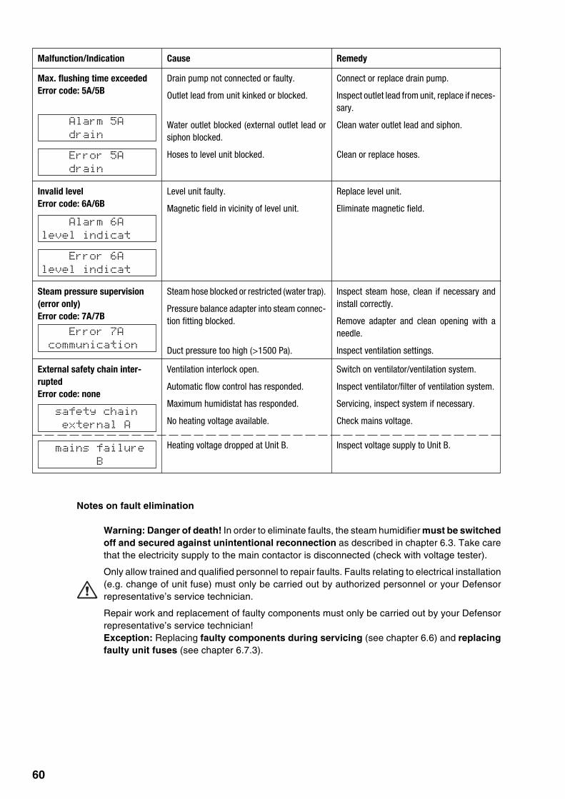
60
Alarm 6A
level indicat
Error 6A
level indicat
Error 7A
communication
safety chain
external A
mains failure
B
Alarm 5A
drain
Error 5A
drain
Malfunction/Indication Cause Remedy
Max. flushing time exceededError code: 5A/5B
Drain pump not connected or faulty.
Outlet lead from unit kinked or blocked.
Water outlet blocked (external outlet lead orsiphon blocked.
Hoses to level unit blocked.
Connect or replace drain pump.
Inspect outlet lead from unit, replace if neces-sary.
Clean water outlet lead and siphon.
Clean or replace hoses.
Invalid levelError code: 6A/6B
Level unit faulty.
Magnetic field in vicinity of level unit.
Replace level unit.
Eliminate magnetic field.
Steam pressure supervision(error only)Error code: 7A/7B
Steam hose blocked or restricted (water trap).
Pressure balance adapter into steam connec-tion fitting blocked.
Duct pressure too high (>1500 Pa).
Inspect steam hose, clean if necessary andinstall correctly.
Remove adapter and clean opening with aneedle.
Inspect ventilation settings.
External safety chain inter-ruptedError code: none
Ventilation interlock open.
Automatic flow control has responded.
Maximum humidistat has responded.
No heating voltage available.
Switch on ventilator/ventilation system.
Inspect ventilator/filter of ventilation system.
Servicing, inspect system if necessary.
Check mains voltage.
Heating voltage dropped at Unit B. Inspect voltage supply to Unit B.
Notes on fault elimination
Warning: Danger of death! In order to eliminate faults, the steam humidifier must be switchedoff and secured against unintentional reconnection as described in chapter 6.3. Take carethat the electricity supply to the main contactor is disconnected (check with voltage tester).
Only allow trained and qualified personnel to repair faults. Faults relating to electrical installation(e.g. change of unit fuse) must only be carried out by authorized personnel or your Defensorrepresentative’s service technician.
Repair work and replacement of faulty components must only be carried out by your Defensorrepresentative’s service technician!Exception: Replacing faulty components during servicing (see chapter 6.6) and replacingfaulty unit fuses (see chapter 6.7.3).

61
6.7.3 Replacing unit fuses
Warning Danger of death! Before replacing the unit fuse the steam humidifier must beswitched off and secured against unintentional reconnection as described in chapter 6.3.Take care that the electricity supply to the main contactor is disconnected (check with voltagetester).
Warning! Electronic components are very sensitive to electrostatic discharge. To protect thesecomponents, measures must be taken against damage from electrostatic discharge whenreplacing the unit fuse (ESD protection).
The unit fuses may only be replaced by trained and qualified personnel.
Important! If the unit fuse blows this is generally due to a faulty unit component. Therefore you shouldcheck these components before replacing the fuse (see table below).
Only use the correct type of fuse according to the following table.
Warning! It is not permitted to use repaired fuses.
Power board (F1..F3, F1...F6 or F1...F9)
Supply module (F2)
Supply module (F1)
Control board (F5)
Fuse Specification Before replacing, check
F1 on supply module 6.3 A, slow-acting Drain pump (blocked or coil faulty)
F2 on supply module 1 A, quick-acting Inlet valve (blocked or coil faulty)
F5 on control board 50mA, quick-acting Control signal
F1…F3 on power board 16 A, super quick-acting Heating elements (on short-circuit)(Mk5 Visual/Process 5-.. and 8-..)
F1…F9 on power board 20 A, super quick-acting Heating elements (on short-circuit)(all other models)
6.7.4 Resetting fault indication “Error”
In order to return the steam humidifier to operation after fault elimination, the steam humidifier must beswitched off for approx. 5 seconds and then switched on again.

62
7 Technical data
Defensor Mk5 Visual/Process
5-.. 8-.. 10-.. 16-.. 20-.. 24-.. 30-.. 40-.. 50-.. 60-.. 80-..
Steam output 0 - 100 % infinitely variable
Number of units 1 1 1 1 1 1 1 1 2 2 2
Steam connection G 1 1/4"
Resolution 1.0 %
Control of steam output
- active 0…20 V (Phase intersect), 0…10 VDC, 1…5 VDC, 0…5 VDC0…4.25 VDC (Potentiometer), 0…1 VDC, 2…10 VDC
0…20 mADC, 4…20 mADC
- passive all potentiometric humidity sensors from 140 Ω…10 kΩ
- On/Off control <2,5 VDC --> Off; ≥2,5 VDC…20 VDC --> On
Duct air pressure Overpressure max. 1500 Pa, Underpressure max. 1000 Pa(for duct pressures outside these values contact your Defensor supplier)
Permissible ambient temperature 1…40 °C
Permissible ambient humidity 1…75 %rh
Water feed
– Connection G 1/2"
– Permissible water pressure 1…10 bar
– Feed temperature 1…40 °C
– Water quality untreated water, fully demineralized water or partially softened water
Water outlet
– Connection Internal-ø= 40 mm
– Outlet temperature max. 90 °C
Weight in kg
– Operation 51 51 52 53 71 73 73 74 1x71 2x73 2x741x73
– Net 36 36 37 38 41 43 43 44 1x41 2x43 2x441x43
Dimensions in mm
– Height 1087 1087
– Width 500 594
– Depth 437 392
Content of lime collector tank in l 5 10
Test certificate SEV, VDE
Type of protection IP21

63
© Axair Ltd. 2000, Printed in Switzerland
Technical data subject to modification

Reg.No. 40002-2
Manufacturer:Axair Ltd. Systems for Air TreatmentA WMH CompanyCH-8808 Pfäffikon (Switzerland), Talstr. 35-37, P.O. BoxTelephone +41 55 416 61 11, Fax +41 55 416 62 62Internet http://www.axair.ch, E-Mail [email protected]
Consulting, Sales and Service: