steady as she goes: reducing flow-induced vibration in ... · steady as she goes: reducing...
TRANSCRIPT
Steady as She Goes: Reducing Flow-Induced Vibration in
Hard Disk Drives
Industrial Representative: F. Hendriks (Hitachi GST)
Faculty: K. Black (Union College), R.J. Braun (Delaware), C. Breward (Oxford, UK), D.Duffy (NASA/GSFC, Retired), L. Mahadevan (Harvard), J. Ockendon (Oxford, UK), C.Please (Southhampton, UK), D. Schwendeman (RPI), B.S. Tilley (Olin College)
Students: D. Boy (Olin College), M. Franklin (Claremont), Z. Kurtz (Delaware)
Summary Presentation: R.J. Braun, 16 June 2006.
Report Preparation: R.J. Braun, D. Schwendeman, and B.S. Tilley
1 Introduction
Making smaller and less expensive disk drives is critical for success in many consumerelectronic devices. One aspect that is under constant examination for improvement is steadyflight of the disk heads. They fly only nanometers above the disks which are rotating at7200 rpm or more. While the spinning of the disks and the viscous entrainment of theair within the drive allows the heads to fly, it also creates dynamic secondary flows thatmay buffet the head. This may necessitate the design of more sophisticated controllers tocombat induced vibration or limit how narrow a track may be.
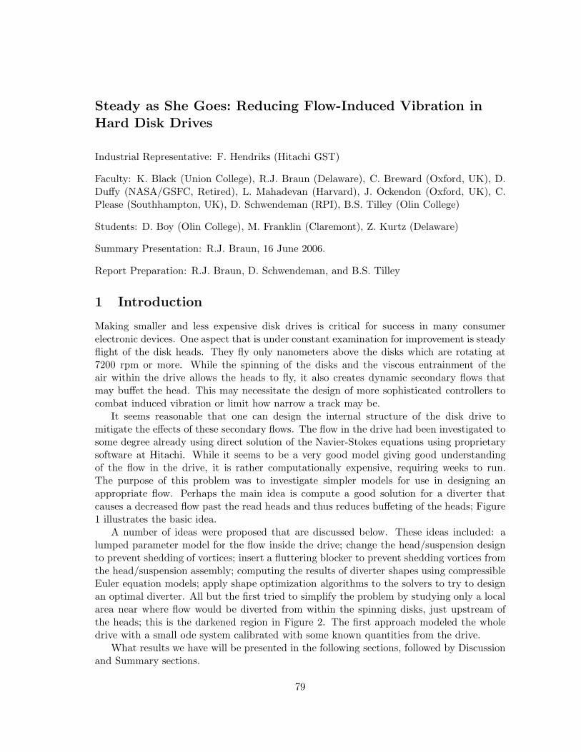
It seems reasonable that one can design the internal structure of the disk drive tomitigate the effects of these secondary flows. The flow in the drive had been investigated tosome degree already using direct solution of the Navier-Stokes equations using proprietarysoftware at Hitachi. While it seems to be a very good model giving good understandingof the flow in the drive, it is rather computationally expensive, requiring weeks to run.The purpose of this problem was to investigate simpler models for use in designing anappropriate flow. Perhaps the main idea is compute a good solution for a diverter thatcauses a decreased flow past the read heads and thus reduces buffeting of the heads; Figure1 illustrates the basic idea.
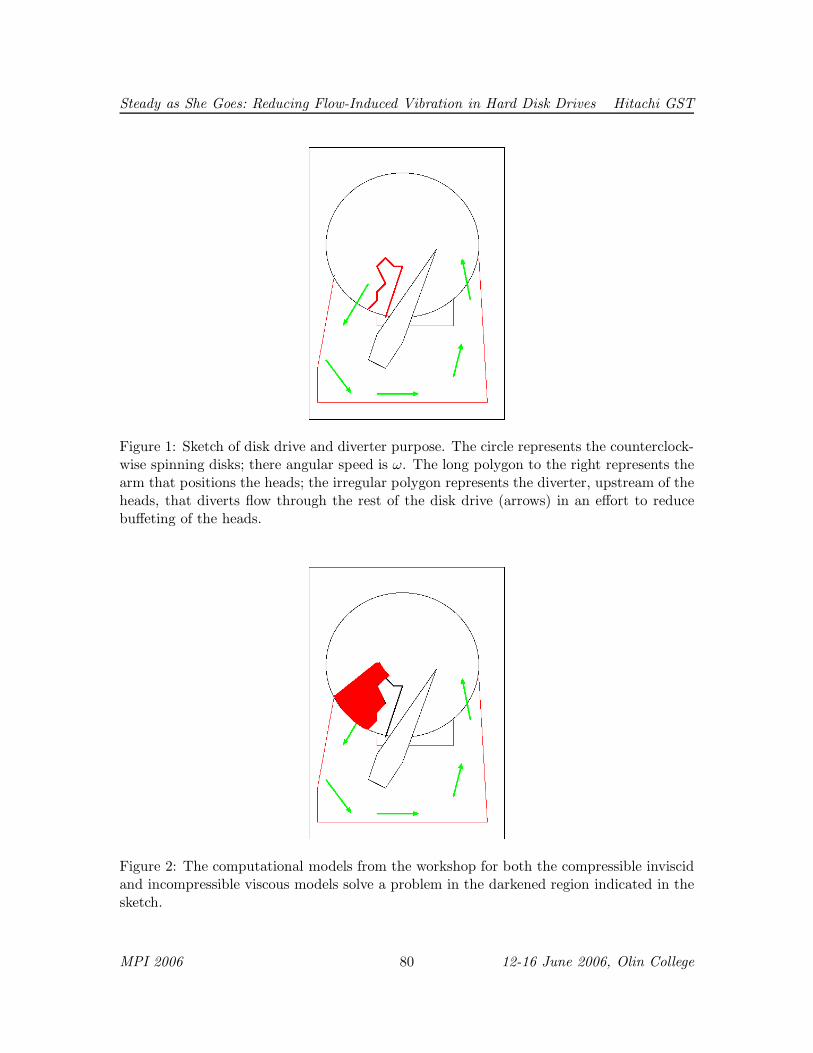
A number of ideas were proposed that are discussed below. These ideas included: alumped parameter model for the flow inside the drive; change the head/suspension designto prevent shedding of vortices; insert a fluttering blocker to prevent shedding vortices fromthe head/suspension assembly; computing the results of diverter shapes using compressibleEuler equation models; apply shape optimization algorithms to the solvers to try to designan optimal diverter. All but the first tried to simplify the problem by studying only a localarea near where flow would be diverted from within the spinning disks, just upstream ofthe heads; this is the darkened region in Figure 2. The first approach modeled the wholedrive with a small ode system calibrated with some known quantities from the drive.
What results we have will be presented in the following sections, followed by Discussionand Summary sections.
79
Steady as She Goes: Reducing Flow-Induced Vibration in Hard Disk Drives Hitachi GST
Figure 1: Sketch of disk drive and diverter purpose. The circle represents the counterclock-wise spinning disks; there angular speed is ω. The long polygon to the right represents thearm that positions the heads; the irregular polygon represents the diverter, upstream of theheads, that diverts flow through the rest of the disk drive (arrows) in an effort to reducebuffeting of the heads.
Figure 2: The computational models from the workshop for both the compressible inviscidand incompressible viscous models solve a problem in the darkened region indicated in thesketch.
MPI 2006 80 12-16 June 2006, Olin College
Steady as She Goes: Reducing Flow-Induced Vibration in Hard Disk Drives Hitachi GST
2 A formulation
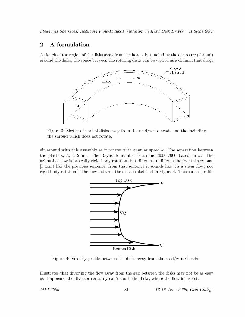
A sketch of the region of the disks away from the heads, but including the enclosure (shroud)around the disks; the space between the rotating disks can be viewed as a channel that drags
Figure 3: Sketch of part of disks away from the read/write heads and the including
the shroud which does not rotate.
air around with this assembly as it rotates with angular speed ω. The separation betweenthe platters, h, is 2mm. The Reynolds number is around 3000-7000 based on h. Theazimuthal flow is basically rigid body rotation, but different in different horizontal sections.[I don’t like the previous sentence; from that sentence it sounds like it’s a shear flow, notrigid body rotation.] The flow between the disks is sketched in Figure 4. This sort of profile
Top Disk
Bottom Disk
V
V/2
V
Figure 4: Velocity profile between the disks away from the read/write heads.
illustrates that diverting the flow away from the gap between the disks may not be as easyas it appears; the diverter certainly can’t touch the disks, where the flow is fastest.
MPI 2006 81 12-16 June 2006, Olin College

Steady as She Goes: Reducing Flow-Induced Vibration in Hard Disk Drives Hitachi GST
There are certainly categories of secondary flows, like Gortler vortices, where the flowleaves the disks and flows through the control and other mechanisms away from the disk.
Several formulations are attempted here. One is a circuit, or lumped parameter modelfor the drive. The remaining ideas involve inviscid flow. One involves changing the shapeof the head/support structure to prevent vortex shedding. Computational models are alsodeveloped in the region indicated in Figure 2. One model will assume that the Reynoldsnumber is large enough to treat the flow as a compressible inviscid flow for which thecompressible Euler equations are solved. Finally, there are results from numerical solutionof the incompressible Navier-Stokes equations.
3 Lumped parameter model
In this approach, the physical flow is reduced to a lumped parameter model in analogywith electric circuit models, and the complex space-time evolution of the actual system isapproximated by discrete elements and ordinary differential equations. If the elements givea sufficiently close approximation to the system, then the model can be used to great effect.This approach is used successfully in vibration analysis [1], heat transfer and cooling ofelectronic equipment [2] and other applications.
In this problem, the analogy with electric circuits is given in Table 1. The following
Electric Hydraulic
Voltage drop, V = IR Pressure drop, p = qrVoltage, [V ] = V Pressure, [p] = Pa
Current, [I] = A Volume Flux, [q] = m3
s
Resistance, [R] = Ω Flow “Drag”, [r] = kgm4s
Table 1: The analogy with electric circuits; the units of the analogous quantities are given.
equivalent circuit approximates the disk drive. There are three paths for flow, with themiddle part of the circuit representing flow that is diverted away from the rotating disks,particularly the part of the disks where the heads fly.
The airflow through a spinning hard drive can be modeled effectively by an analogybetween an electric circuit and the hydraulic behavior of the air flowing through the harddrive device. The quantities are outlined Table 1: The effective circuit is shown in Figure 5.From Kirchhoff’s laws, we are able to use the effective circuit to come up with the followingdimensional system of equations
q = qm + qb,
∆p1 = qbrb,
∆p1 = αψ −(
kpψ +α
β
)
q,
∆p1 = −α(2π − ψ) +
(
rm + kp(2π − ψ) +α
β
)
qm,
MPI 2006 82 12-16 June 2006, Olin College

Steady as She Goes: Reducing Flow-Induced Vibration in Hard Disk Drives Hitachi GST
P1
∆
P1
∆
qb
2P∆qm
r
r
r
rm
b∆P2
w
w
1
2
q
2π − ψ
Figure 5: Effective circuit model. The hydraulic circuit of the air flow in the hard disk driveis shown at the right. The spinning disks produce an effective pressure drop that drives theflow q. Note that the angle ψ in the model describes the arc outside the “middle-channel”.
by analyzing the flow of air q through the entire device, around the bottom loop, aroundthe upper loop, and through the center, respectively. The physical resistance of the bypassis rb, the pressure drop across rw2 is given by kpψq (where kp is a proportionality constantso that rw2 ∝ ψ), and the introduction of pressure to the system by the pump is given byα(ψ− q/β). The parameter β represents the “mass flux” through the device which is givenby
Mass Flux =
∫ R1
R0
V ·Hdr = H
∫ R1
R0
ωrdr =1
2Hω(R2
1 −R20),
where the radii R0 and R1 represent the inner and outer radii of the hard drive, respectively.As shown in Figure 6 we rescale the variables as
q = βq,
∆P1 = [p] = αp,
r = kpr,
where the overbar represents dimensionless variables. This leads to the following dimen-sionless system
q = qm + qb, (1)
p = Mqbrb, (2)
p = ψ − (1 +Mψ)q, (3)
p = −(2π − ψ) + (Mrm +M(2π − ψ) + 1)qm. (4)
where the parameter M ≡ kpβ/α.From (4) we can find an equivalent expression for rm
rm =1
M
p+ (2π − ψ)
qm− [M (2π − ψ) + 1]
(5)
MPI 2006 83 12-16 June 2006, Olin College

Steady as She Goes: Reducing Flow-Induced Vibration in Hard Disk Drives Hitachi GST
Figure 6: Air pumping characteristics of the spinning disks. Top: Pressure as a function ofrotation rate. Bottom: Angle dependence.
The remaining equations (1)-(3) can be solved in terms of the flow in the middle section qm
q =ψ +Mrbqm
1 +Mψ +Mrb(6)
qb =ψ − (1 +Mψ)qm1 +Mψ +Mrb
(7)
p = Mrbqb . (8)
With this and (5), we find that
rm =rbψ
qm [1 +Mψ +Mrb]− 1
M
2Mrb [1 +Mπ] + (1 +Mψ) [1 +M(2π − ψ)]
1 +Mψ +Mrb
. (9)
Since rm ≥ 0, this gives us an upper limit on the value of qm, which we call q∗,
q∗ =Mrbψ
2Mrb [1 +Mπ] + (1 +Mψ) [1 +M(2π − ψ)]. (10)
The power P of the circuit is given by
P = (rm + ψ) q2m + rbq2b + (2π − ψ)q2 ,
which can with (6)-(9) be written in the form
P = Aq2m +Bqm + C , (11)
MPI 2006 84 12-16 June 2006, Olin College

Steady as She Goes: Reducing Flow-Induced Vibration in Hard Disk Drives Hitachi GST
where
A = ψ +
[
rb(1 +Mψ)2 + (2π − ψ)(Mrbψ)2]
(1 +M(ψ + rb))2−
1
M
2Mrb [1 +Mπ] + (1 +Mψ) [1 +M(2π − ψ)]
1 +Mψ +Mrb
(12)
B =rbψ
[1 +Mψ +Mrb]+ 2
[Mrbψ(2π − ψ) − (1 +Mψ)rb]
(1 +M(ψ + rb))2(13)
C =ψ2 [rb + 2π − ψ]
(1 +M(ψ + rb))2. (14)
The optimization problem can then be phrased in the following way: Given a prescribedpower level P ∗ = Aq∗2 + Bq∗ + C, where q∗ is found in (10), find a qm such that P = P ∗
and qm < q∗. This problem requires, at least, that A < 0 and P ∗ > C, and its solution isgiven by
qm =B
|A| − q∗ > 0 .
To better describe this process, recall that in the case without an obstruction (rm = 0)the air flows more easily in the disks than through the remainder of the casing, or rb ≫ rw.This ansatz leads to the following asymptotic forms,
rb =r
M,M → 0 , (15)
and rm = O(1/M). Using (15) in (11), we find
−r(2r + 3) q2m + [ψ(1 + r) − 2] qm + ψ2 = 0 . (16)
A typical graph of the power as a function of the middle air flow rate qm is shown in Figure7a. Notice that the reference power level is given with qm = q∗, and that a smaller flowrate exists which gives the same power level. In Figure 7b, we show the equivalent graphbut with the effective additional middle resistance Mrm shown along the vertical axis.
Hence, this lumped parameter model suggests that there is a resistance that will bothlower the flow around the reader arm with potentially a small power cost. The remainingsections of the report discuss how to determine the connection between the fluid mechanicsand this resistance, and if there are other effects which mitigate the viability of this model.
4 Compressible Navier-Stokes Model
In this section, we focus on small part of the flow field where the fluid is diverted fromflowing with the rotating disks and is sent through the remaining area of the drive. Theidea is to explore the trade off between getting more flow diverted vs. higher torque requiredto spin the disks. This is a serious design issue that can be explored more rapidly than fora full direct computation. Here we frame the question as follows: What function for thediverter shape, f(y), will divert the most momentum out through the bottom outlet?
MPI 2006 85 12-16 June 2006, Olin College

Steady as She Goes: Reducing Flow-Induced Vibration in Hard Disk Drives Hitachi GST
0 0.5 1 1.5 2
21
22
23
24
25
qm
P
0 0.5 1 1.5 20
5
10
15
20
qm
r m
(a) (b)
Figure 7: Plot of power levels (a) and effective middle-channel resistance rm as a functionof the flow rate through the middle section qm. The green dashed curve corresponds to thepower P ∗. Parameter values in this plot are M → ∞, r = 1, and ψ = 3π/2.
For this optimization problem, consider the shaded region in Figure 2. We want tomaximize the momentum through the bottom outlet:
maxf
∫
outlet(ρ~v) · ~n ds
. (17)
At the same time we have constraints
∂tρ+ ∇ · (ρ~u) = 0, (18)
∂t (ρ~v) + ∇ · (ρ~v ⊗ ~u) + ∇P − µ∇2~u− 1
3µ∇ (∇ · ~u) = 0, (19)
∂t(
pρ1.4)
+ ~u · ∇(
pρ1.4)
= 0, (20)
for isentropic flow, with appropriate boundary conditions.The basic idea of the approach is to define a function based on the boundary, f ,
J(f) =
∫
outlet(ρ~v) · ~n ds (21)
where f is from the set of permissible boundaries, V . If we are careful with our definitionsthen V is a Hilbert space with an associated inner product. Then we may use steepestdescent method to optimize. In that case, we determine a search direction based on agradient
J(f + w) = J(f)+ < GradfJ,w > +o(‖w‖), (22)
for any f, g ∈ V . Choose
w = a GradfJ, (23)
MPI 2006 86 12-16 June 2006, Olin College

Steady as She Goes: Reducing Flow-Induced Vibration in Hard Disk Drives Hitachi GST
where a is a free parameter, 0 < a ≪ 1. One can define a search direction based on asteepest descent scheme. This approach can be problematic because: (a) convergence canbe slow; (b) choosing the free parameter may require multiple solves
An example of a local problem to which the shape optimization could be applied.Results for this problem are shown in Figure 8. These computations show a developing
layer by the diverter; further computations are needed in a geometry such as this.A more promising approach may be to choose a search direction based on the “PDE
Sensitivity Equation Method” (see [3])
5 Incompressible Navier-Stokes T-channel
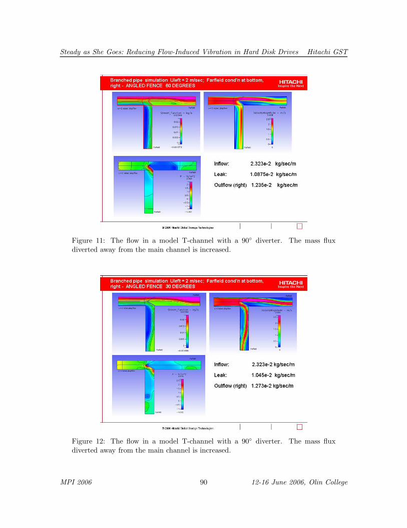
The following results were found by Drs. Hendriks and Duffy using proprietary Navier-Stokes solvers. There is a series of results for a T-channel; the flow enters at the left;passing straight through corresponds to air following the disks. Flow turning down theother channel corresponds to being diverted away from the disks and heads and throughthe rest of the drive. The series of results that now follow have diverters at various angles,or no wall at all. The diverter in this sequence of results is a thin rectangular wall stickingout into the main channel at an angle of 30, 60 or 90 with respect to the side wall of thechannel.
The first result, shown in Figure 9 is for a T-channel without any diverter wall at all.The next results, shown in Figures 10 through 12, are for a T-channel with a diverter wallat 90, 60 and 30 angles to the channel wall. Note that the diverter wall is constant lengthhere. We see that the maximum diversion occurs for the 90 diverter. It seems likely thatthe optimum diversion came from the largest fraction of the straight channel being blockedby the diverter.
6 Inviscid Flow
Perhaps the biggest contribution from trying approaches like this was to use a local problemto try to design a diverter; this reduced the problem to a much smaller problem and morerapidly solved problem than that posed by a direct Navier-Stokes simulation of the wholedisk drive.
6.1 Ideas from Complex Variables
In this subsection, we list some ideas that in principle employ complex variables.One idea is to put a cross plate on the end of a splitter plate on the leading edge of
the actuator arm, as illustrated in Figure 13. Complex variable methods could be used todesign the plate and splitter to put a separating streamline as illustrated.
6.2 Compressible Flow
Compressible flow in a T-channel with various diverter geometries was considered. Theflow is assumed to be inviscid and thus described by the Euler equations, which, for two-
MPI 2006 87 12-16 June 2006, Olin College

Steady as She Goes: Reducing Flow-Induced Vibration in Hard Disk Drives Hitachi GST
Figure 8: Density (top) and norm of the velocity (bottom) for a local computationnear the diverter. The diverter in this computation is the inclined line at the right;the vertical line at the left edge is the shroud. The horizontal boundary at the topis an inlet from the spinning disk and the bottom boundary is the outlet into therest of the drive away from the platters.
MPI 2006 88 12-16 June 2006, Olin College

Steady as She Goes: Reducing Flow-Induced Vibration in Hard Disk Drives Hitachi GST
Figure 9: The flow in a model T-channel without any diverter. The mass fluxdiverted away from the main channel is small.
Figure 10: The flow in a model T-channel with a 90 diverter. The mass fluxdiverted away from the main channel is increased.
MPI 2006 89 12-16 June 2006, Olin College
Steady as She Goes: Reducing Flow-Induced Vibration in Hard Disk Drives Hitachi GST
Figure 11: The flow in a model T-channel with a 90 diverter. The mass fluxdiverted away from the main channel is increased.
Figure 12: The flow in a model T-channel with a 90 diverter. The mass fluxdiverted away from the main channel is increased.
MPI 2006 90 12-16 June 2006, Olin College

Steady as She Goes: Reducing Flow-Induced Vibration in Hard Disk Drives Hitachi GST
Separating Streamline
Cross plate
Actuator armdead
dead
U
suppress vortex sheddingSuggested length to
Figure 13: The splitter with a cross plate on the leading edge of the actuator armcould be designed to have a separating streamline meet the corner of the actuatorarm. The splitter plate on the trailing edge (admittedly for viscous effects), couldeliminate vortex shedding.
dimensional flow, take the form
ut + fx(u) + gy(u) = 0,
where
u =
ρρuρvρE
, f(u) =
ρuρu2 + pρuv
u(ρE + p)
, g(u) =
ρvρuv
ρv2 + pv(ρE + p)
.
The state of the flow at a position (x, y) and time t is given by u(x, y, t) which involves thedensity ρ, the velocity (u, v) and the total energy E. The later has the form
E =p
(γ − 1)ρ+
1
2
(
u2 + v2)
,
for an ideal gas with ratio of specific heats γ.Numerical solutions of the Euler equations were obtained using the flow solver CGCNS
which is part of the Overture framework of codes [4]. The flow domain was discretized usinga composite overlapping grid which consists of a set of structured curvilinear grids thatoverlap where they meet [5]. This discretization technique enables a smooth and accuraterepresentation of a wide range of complex flow geometries, including the ones consideredin this section. The governing equations are solved numerically using a time-dependent,conservative, shock-capturing scheme. In this scheme, the numerical flux calculations areperformed using a second-order, slope-limited Godunov method with Roe-type approximate
MPI 2006 91 12-16 June 2006, Olin College
Steady as She Goes: Reducing Flow-Induced Vibration in Hard Disk Drives Hitachi GST
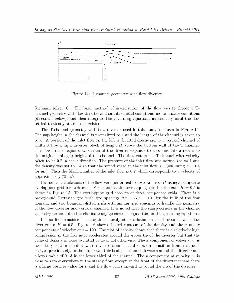
Figure 14: T-channel geometry with flow diverter.
Riemann solver [6]. The basic method of investigation of the flow was to choose a T-channel geometry with flow diverter and suitable initial conditions and boundary conditions(discussed below), and then integrate the governing equations numerically until the flowsettled to steady state if one existed.
The T-channel geometry with flow diverter used in this study is shown in Figure 14.The gap height in the channel is normalized to 1 and the length of the channel is taken tobe 8. A portion of the inlet flow on the left is diverted downward to a vertical channel ofwidth 0.4 by a rigid diverter block of height H above the bottom wall of the T-channel.The flow in the region downstream of the diverter expands to accommodate a return tothe original unit gap height of the channel. The flow enters the T-channel with velocitytaken to be 0.2 in the x direction. The pressure of the inlet flow was normalized to 1 andthe density was set to 1.4 so that the sound speed in the inlet flow is 1 (assuming γ = 1.4for air). Thus the Mach number of the inlet flow is 0.2 which corresponds to a velocity ofapproximately 70 m/s.
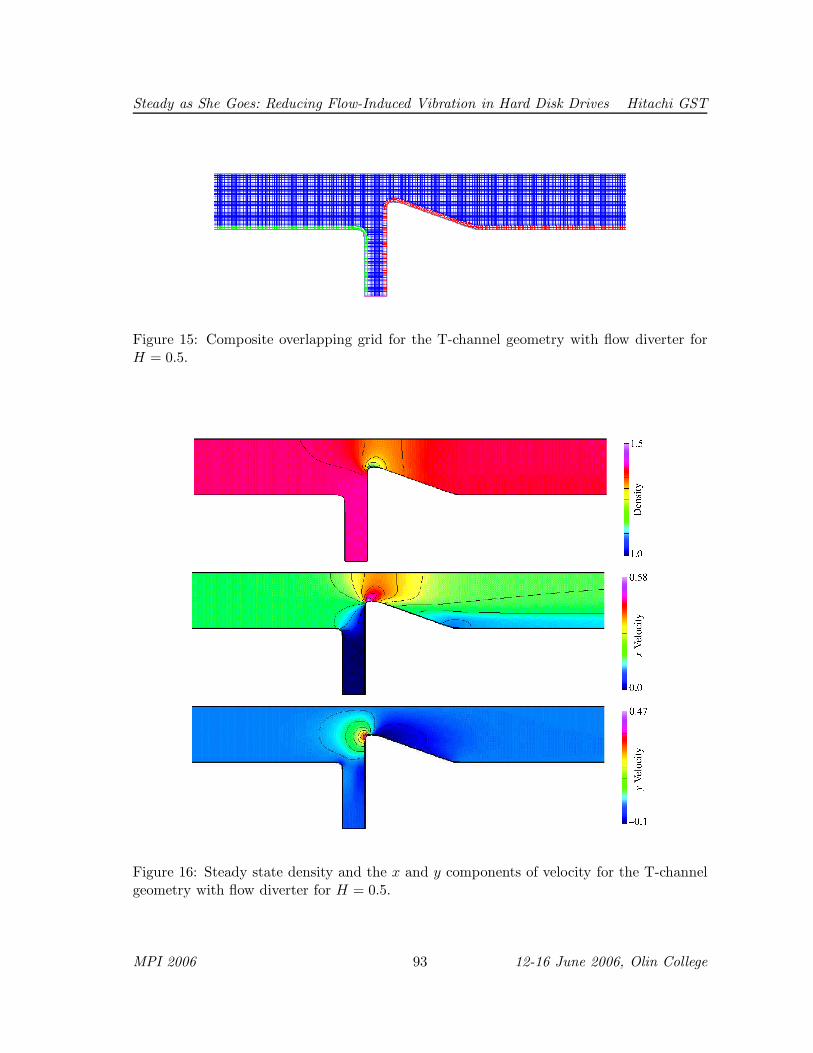
Numerical calculations of the flow were performed for two values of H using a compositeoverlapping grid for each case. For example, the overlapping grid for the case H = 0.5 isshown in Figure 15. The overlapping grid consists of three component grids. There is abackground Cartesian grid with grid spacings ∆x = ∆y = 0.01 for the bulk of the flowdomain, and two boundary-fitted grids with similar grid spacings to handle the geometryof the flow diverter and vertical channel. It is noted that the sharp corners in the channelgeometry are smoothed to eliminate any geometric singularities in the governing equations.
Let us first consider the long-time, steady state solution in the T-channel with flowdiverter for H = 0.5. Figure 16 shows shaded contours of the density and the x and ycomponents of velocity at t = 120. The plot of density shows that there is a relatively highcompression in the flow as it accelerates around the upper tip of the diverter but that thevalue of density is close to initial value of 1.4 otherwise. The x component of velocity, u, isessentially zero in the downward diverter channel, and shows a transition from a value of0.23, approximately, in the upper two thirds of the channel downstream of the diverter anda lower value of 0.13 in the lower third of the channel. The y component of velocity, v, isclose to zero everywhere in the steady flow, except at the front of the diverter where thereis a large positive value for v and the flow turns upward to round the tip of the diverter.
MPI 2006 92 12-16 June 2006, Olin College
Steady as She Goes: Reducing Flow-Induced Vibration in Hard Disk Drives Hitachi GST
Figure 15: Composite overlapping grid for the T-channel geometry with flow diverter forH = 0.5.
Figure 16: Steady state density and the x and y components of velocity for the T-channelgeometry with flow diverter for H = 0.5.
MPI 2006 93 12-16 June 2006, Olin College

Steady as She Goes: Reducing Flow-Induced Vibration in Hard Disk Drives Hitachi GST
Figure 17: Density and the x-component of velocity at x = 8 for the T-channel geometrywith flow diverter for H = 0.5.
The behavior of the density and normal component of velocity at the two outlets of theT-channel are shown in Figures 17 and 18. The solution at these locations may be used todetermine the mass flow rate at each outlet. For example, the behavior of the flow at theoutlet of the T-channel downstream of the diverter is shown in Figure 17. Here, we notethat the density is nearly constant taking a value slightly less that its upstream value of1.4 while the velocity shows a transition from u = 0.13 near the bottom of the channel aty = 0 to u = 0.23, approximately, near the top of the channel at y = 1. (The color of themarks in the figure correspond to the colors of the component grids in Figure 15 and thusindicate from which grid the solution is obtained.) The mass flow rate is computed using anumerical quadrature of the formula
Q0 =
∫ 1
0ρ(x, y)u(x, y) dy, x = 8,
and found to be Q1 = 0.2712. In contrast, the behavior of the flow at the outlet of thedownward diverter channel is shown in Figure 18, and these plots show very little variationin both the density and velocity, v. The mass flow rate here is given by
Q1 = −∫ b
aρ(x, y)v(x, y) dx, a = 3, b = 3.4, y = −1.2,
and found to be Q1 = 0.0088. The sum of Q0 and Q1 equals the mass flow rate into theT-channel which is 0.28. Hence, for this channel geometry, only 3.1% of the mass from theinlet flow is diverted downward from the main flow stream.
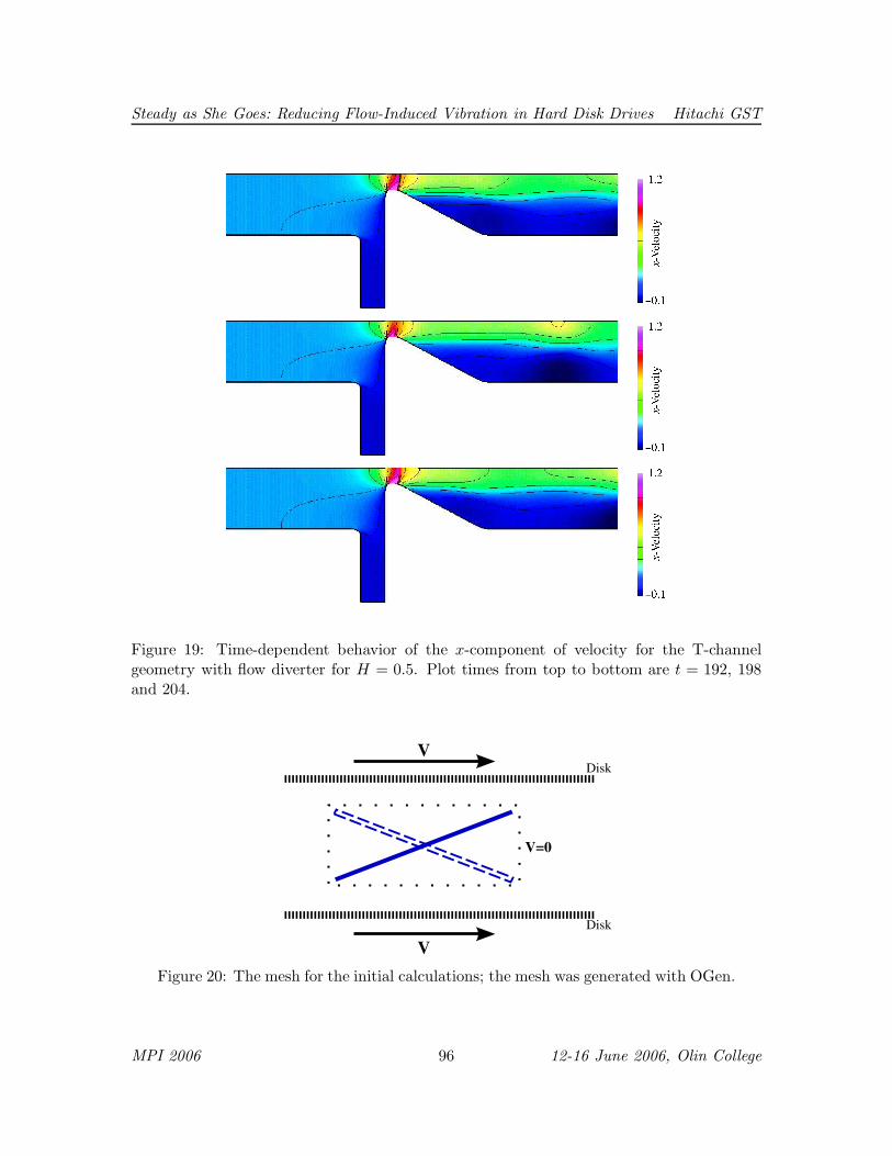
A T-channel with a larger value ofH for its diverter was considered to study the resultingflow behavior and to determine whether a larger fraction of the main flow stream could bediverter. For example, the behavior of the flow for the case H = 0.75 is shown in Figure 19.For this value it was found that the flow does not achieve a steady state due to vortices shedperiodically from the upper tip of the diverter. The plots in the figure show the density attimes t = 192, 198 and 204, and these are provided to give some indication of the unsteady
MPI 2006 94 12-16 June 2006, Olin College

Steady as She Goes: Reducing Flow-Induced Vibration in Hard Disk Drives Hitachi GST
Figure 18: Density and the y-component of velocity at y = −1.2 for the T-channel geometrywith flow diverter for H = 0.5.
behavior. This unsteadiness is considered to be undesirable for the downstream flow as itinteracts with the read/write head and its support (not modeled in this simulation). Thus,we find a trade off between the desire to increase the mass flow rate in the diverted flowand unsteadiness of the main flow downstream of the diverter.
7 Fluttering Blocker
A suggestion was made by Dr. L. Mahadevan to consider an obstacle to be place ahead ofthe flying heads, between the disks, that fluttered and presumably disrupted the formationof von Karman vortices behind the disk heads. An illustration of the idea is shown in Figure20. In favor of the idea is the existence of many flutter modes that could help destroy anyvortices otherwise shed from the heads and high drag could help divert flow from the heads.On the other hand fabrication issues for device likely to be delicate and flexible could bedaunting. Further, the frequencies at which the device would have to operate would be inthe audible regime. The noise produced by the fluttering device eliminates this method tobe used due to customer demands for quiet disk-drive operation.
8 Discussion
The methods to eliminate the flow between disks in a hard disk drive from impacting thereading of data has been significantly challenging. In this report, we note that the presenceof an obstruction requires more power for the device. However, the lumped parametermodel suggests that the power cost of the obstruction may not be that severe. A betterquantitative study based on the effective values of the parameters to specific drives needsto be investigated in order to determine if this model is reliable.
The additional modeling rests on understanding the fluid flow in the region local tothe diverter. In all cases the geometry of the diverter was simplified to a straight line atan angle from the unobstructed flow direction. Preliminary numerical results show that
MPI 2006 95 12-16 June 2006, Olin College
Steady as She Goes: Reducing Flow-Induced Vibration in Hard Disk Drives Hitachi GST
Figure 19: Time-dependent behavior of the x-component of velocity for the T-channelgeometry with flow diverter for H = 0.5. Plot times from top to bottom are t = 192, 198and 204.
Disk
V
V=0
Disk
V
Figure 20: The mesh for the initial calculations; the mesh was generated with OGen.
MPI 2006 96 12-16 June 2006, Olin College

Steady as She Goes: Reducing Flow-Induced Vibration in Hard Disk Drives Hitachi GST
Figure 21: The Ultrastar C10K147 hard disk (shown on the right) implements the flowdiverter to help increase disk performance.
the flow can be diverted away from the reader arm appropriately. A steady Navier-Stokessimulation of a T-junction suggests that the best diverter angle is normal to the mean flowtoward the diverter. However, a time-dependent investigation of Euler’s equations suggeststhat minimizing the mass flow rate toward the reader arm induces unsteady behavior thatpropagates toward the reader arm. Such behavior could not have been predicted from alumped parameter model.
In conclusion, a full study of the diverter shape to be used to minimize the buffeting feltby the reader arm from the unsteady flow is needed. Needless to say that this study is neededto help improve the design and performace of these hard disks. Between the workshop andthe proceedings, Hitachi has come out with a server hard disk that implements this diverteridea (see Figure 21).
References
[1] L. Meirovich, Elements of vibraition analysis, McGraw-Hill, New York, 1980.
[2] A.D. Krauss, A. Bar-Cohen, Thermal analysis and control of electronic equipment,McGraw-Hill, New York: 1983.
[3] J. Borggaard and K. Burns, J. Comp. Phys. (1997).
[4] W. D. Henshaw, A primer for writing PDE codes with Overture, Tech. Rep. UCRL-MA-132231, LLNL (1998).
MPI 2006 97 12-16 June 2006, Olin College

Steady as She Goes: Reducing Flow-Induced Vibration in Hard Disk Drives Hitachi GST
[5] G. Chesshire, W. Henshaw, Composite overlapping meshes for the solution of partialdifferential equations, J. Comp. Phys. 90 (1990) 1–64.
[6] W. D. Henshaw, D. W. Schwendeman, An adaptive numerical scheme for high-speedreactive flow on overlapping grids, J. Comput. Phys. 191 (2) (2003) 420–447.
MPI 2006 98 12-16 June 2006, Olin College