standards update notice (sun) issued: april 27, 2018 · c22.2 no. 60335-2-40:12/ul 60335-2-40 first...
TRANSCRIPT
STANDARDS UPDATE NOTICE (SUN)
ISSUED: April 27, 2018
SFT-ETL-OP-29c (December 15, 2017) Standards Update Notice KR/KM Page 1 of 22
Standard Number: UL 60335-2-40 / CSA C22.2 No. 60335-2-40
Standard Name: Household and Similar Electrical Appliances - Safety - Part 2-40: Particular
Requirements for Electrical Heat Pumps, Air-Conditioners and Dehumidifiers
Standard Edition and Issue Date: 2nd
/ 2nd
Edition Dated September 15, 2017
Date of Revision: September 15, 2017
Date of Previous Revision of Standard: 1st
Edition Dated May 15, 2017
Effective Date: Until November 30, 2020, all new submittals of electrical heat pumps, air-
conditioners and dehumidifiers shall be evaluated to the applicable requirements of CAN/CSA
C22.2 No. 60335-2-40:17/UL 60335-2-40 Second Edition, or, if requested in writing, the
products may continue to be evaluated for compliance with standard Update No.1 to CAN/CSA
C22.2 No. 60335-2-40:12/UL 60335-2-40 First Edition.
Between November 30, 2020 and the effective date of November 30, 2022, all new submittals
of electrical heat pumps, air- conditioners and dehumidifiers shall be evaluated to the
applicable requirements of CAN/CSA C22.2 No. 60335-2-40:17/UL 60335-2-40 Second Edition.
After November 30, 2022, all CSA certified electrical heat pumps, air- conditioners and
dehumidifiers covered by CSA standards C22.2 No.117, C22.2 No.236, CAN/CSA C22.2 No.
60335-2-40:12, and UL standards UL 484, UL1995, UL 60335-2-40 First Edition shall comply with
CAN/CSA C22.2 No. 60335-2-40:17/UL 60335-2- 40 Second Edition.
Impact Statement: A review of all Listing Reports is necessary to determine which products comply with
new/revised requirements and which products will require re-evaluation. NOTE: Effective immediately, this
revised standard will be exclusively used for evaluation of new products unless the Applicant requests in
writing that current requirements be used along with their understanding that their listings will be withdrawn
on Effective Date noted above, unless the product is found to comply with new/revised requirements.
Overview of Changes:
• Realignment of second edition of UL 60335-2-40/CSA C22.2 No. 60335-2-40 with current edition of IEC
60335-2-40
• Requirements for pressure vessels, dehumidifiers, flammable refrigerants, transcritical CO2, contractor
reliability, partial units, pole disconnected electric heat, Ni-chrome wire, polymeric materials
Specific details of new/revised requirements are found in table below.
STANDARD INFORMATION
EFFECTIVE DATE OF NEW/REVISED REQUIREMENTS
IMPACT, OVERVIEW, AND ACTION REQUIRED

2 of 22
If the applicable requirements noted in the table are not described in your report(s), these requirements will
need to be confirmed as met and added to your report(s) such as markings, instructions, test results, etc. (as
required).
Client Action Required:
Information – To assist our Engineer with review of your Listing Reports, please submit technical information in
response to the new/revised paragraphs noted in the attached or explain why these new/revised requirements
do not apply to your product (s).
Current Listings Not Active? – Please immediately identify any current Listing Reports or products that are no
longer active and should be removed from our records. We will do this at no charge as long as Intertek is
notified in writing prior to the review of your reports.
CLAUSE VERDICT COMMENT
Additions to existing requirements are underlined and deletions are shown lined out
below.
1 Info Scope
1DV.4
DR Modification of the eighth paragraph of Clause 1 as follows:
Replace “ISO 5149” with applicable refrigeration mechanical codes, if any
ANSI/ASHRAE 15 Safety Standard for Refrigeration Systems (USA) and CSA B52
Mechanical Refrigeration Code (Canada). This clause does not apply for Mexico.
7 Info Marking and instructions
7.1DV.1
New clause added;
DR Modification of Clause 7.1 to add the following dashed items after the first
dashed item after “Addition:”
– Motor ratings (FLA, Horsepower)
For motors controlled by adjustable speed drive, FLA shall be replaced with
either the motor’s MOC or the rated input current of the power conversion
equipment. When there is bypass utilized, it shall be the larger of the motor’s
MOC, the rated input current to the power conversion equipment or the full
load amperes of the motor.
– Total input current (cord connected units)
– Minimum circuit ampacity (MCA) (permanently connected equipment only)
– Motor compressor ratings (RLA and LRA)
For motor-compressors controlled by adjustable speed drive, (RLA and LRA)
shall be replaced with the rated input current of the power conversion
equipment.
STANDARD INFORMATION
3 of 22
– Rating of over current protective device (permanently connected equipment
only)
– Branch circuit selection current (BCSC) (if RLA exceeds 64% of MCC)
– Manufacturing date or date code and location if the product is produced in
more than one location
7.1DV.2
New clause added;
Note 1DV In Canada, the equivalent French wording for the warning is as follows:
AVERTISSEMENT
L’appareil doit être installé, utilisé et entreposé dans un endroit dont la superficie
du plancher est supérieure à «X» m2 (applicable uniquement aux appareils qui ne
sont pas fixes)
7.1DV.3
New clause added;
D1 Modification of Clause 7.1 by adding the following to the seventh paragraph,
regarding minimum room size X:
The X in the marking shall not be required if the refrigerant charge of the appliance
is less than or equal to m1 according to Annex GG.1.1.
7.1ADV
New clause added;
D1 Addition of the following clauses to Clause 7 of this Part 2:
7.1ADV.1
New clause added;
If the refrigerant is flammable the air conditioning equipment shall have red,
Pantone® Matching System (PMS) #185 marked service ports, pipes, hoses, and
other devices through which the refrigerant is serviced. This colour shall be
present at all service ports and where service puncturing or otherwise creating an
opening from the refrigerant circuit to the atmosphere might be expected (e.g.,
process tubes). The colour mark shall extend at least 25 mm (1 inch) from the
refrigerant servicing point and shall be replaced if removed.
7.1ADV.2
New clause added;
If refrigerant is flammable, the markings specified in Clauses 7.1ADV.3 to 7.1ADV.5
in letters at least 6.35 mm (0.25 in) high shall be permanently affixed to the
equipment in the location indicated.
7.1ADV.3
New clause added;
The following markings, or the equivalent, shall be located on the outside of the
product when flammable refrigerants are employed:
– “DANGER – Risk Of Fire Or Explosion. Flammable Refrigerant Used. To Be
Repaired Only By Trained Service Personnel. Do Not Puncture Refrigerant

4 of 22
Tubing.”
– “CAUTION – Risk Of Fire Or Explosion. Dispose Of Properly In Accordance With
Federal Or Local Regulations. Flammable Refrigerant Used.
Note In Canada, the equivalent French wording for the markings is as follows:
– “DANGER – Risque d’incendie ou d’explosion. Contient un frigorigène
inflammable. Confier la réparation à une personne qualifiée. Ne pas perforer la
tubulure contenant le frigorigène.”
– “ATTENTION – Risque d’incendie ou d’explosion. Mettre au rebut conformément
aux règlements fédéraux ou locaux. Contient un frigorigène inflammable.”
7.1ADV.4
New clause added;
The following markings, or the equivalent, shall be located inside of the product
near the compressor when flammable refrigerants are employed.
– “CAUTION – Risk Of Fire Or Explosion. Flammable Refrigerant Used. Consult
Repair Manual/Owner’s Guide Before Attempting To Service This Product. All
Safety Precautions Must Be Followed”
Note In Canada, the equivalent French wording for the marking is as follows:
– “ATTENTION – Risque d’incendie ou d’explosion. Contient un frigorigène
inflammable. Consulter la notice de réparation/utilisation avant de tenter de
réparer ce produit. Respecter toutes les mesures de sécurité. ”
7.1ADV.5
New clause added;
The shipping carton of an air conditioner that employs a flammable refrigerant
shall be marked with the following or equivalent:
– “Caution – Risk of Fire or Explosion due to Flammable Refrigerant Used. Follow
Handling Instructions Carefully in Compliance with National Regulations.”
Note In Canada, the equivalent French wording for the marking is as follows:
– ATTENTION – Risque d’incendie ou d’explosion en raison du frigorigène
inflammable. Respecter le mode d’emploi pour assurer la conformité aux
règlements nationaux.
7.6DV
New clause added;
DE Modification by adding the following note to Clause 7.6:
Note 1: DV In Canada, the equivalent French wording for warning symbol W021 of

5 of 22
ISO 7010 is “Avertissement: risque d’incendie/matériaux inflammables”.
7.103DV
DR Add the following to Clause 7 of the Part 2:
Cord-connected appliances shall be marked with the following:
– If the marked ampere rating of the unit exceeds 50% of the rating of the
branch circuit to which it will be connected, the unit shall be marked “Use on
Single Outlet Circuit Only”. This marking shall be adjacent to the cord
entrance.
Exception: The marking on a unit with a 15 ampere attachment plug may read:
“Use on Single Outlet Circuit or 20 Ampere Circuit”, if the marked rating of the unit
does not exceed 10 amperes.
– Statement requiring that a damaged cord be replaced with one supplied by
the unit manufacture and not repaired.
11 Info Heating
11.2.1DV.1
New clause added;
DE Modification of 11.2.1 to add a Note as follows:
Note 1: For horizontal ducted products, reference Figure 101b, rotated 90 degrees
counter clockwise.
11.2.1DV.2
New clause added;
D2 Modification of Clause 11.2.1 in this Part 2 by addition of the following:
For the test of Clause 11 and Clause 19, the distance from the air outlet opening of
the appliance to the furthest point on the test duct, perpendicular to the outlet
opening, shall be no more than value of:

6 of 22
– For upflow appliances (AB)1/2 as shown in Figure 101a or the minimum
distance specified by the manufacturer, whichever is lower.
– For downflow appliances [300 + (AB)1/2] as shown in Figure 101b or the
minimum distance specified by the manufacturer, whichever is lower.
Note 2: Appliances, may be specified by the manufacturer for use in applications
with limited space for the appliance and connected ducts. Examples:
– For upflow appliances intended for use in manufactured (mobile) homes,
the combined height of the appliance and ducts are typically limited to 2.1m
(7 ft) minus the specified clearance to combustible material.
– For downflow appliances intended for use in manufactured (mobile) homes,
the distance from the air outlet opening to the furthest point on the test duct,
perpendicular to the outlet opening is typically reduced to not less than [25.4
+ (AB)1/2
].
Table 3DV
D2 Modification of Table 3 of the Part 2 as follows:
Change maximum temperature for “Material used as insulation, other than that
specified for wires and windings: impregnated or varnished textile, paper or press-
board” from ″95°C″ to ″90°C″
Change maximum temperature for “– polytetrafluoroethylene” from ″290°C″ to
″205°C″
Replace footnote a) of Table 3 with the following:
a Not required for motor-compressors that comply with Annex AA of IEC 60335-2-
34.
Add the following to Table 3:
Table 3DV – Temperature limits Parts Temperature
°C Surfaces of product, discharge plenum, and duct at points of specified zero clearance to test enclosure
Surfaces of test enclosure where clearance more tha n zero to combustible material is specified
92
92
13 Info Leakage current and electric strength at operating temperature

7 of 22
13.1DV
New clause added;
D2 Modification of Clause 13.1 by addition to the Part 1:
For appliance with supplementary heat or provisions for supplementary heat
tested per Clause 19.2, the leakage and dielectric test of Clause 13 of the Part 2
shall be conducted following completion of the tests of Clause 19.
19 Info Abnormal operation
19.1
Modification:
Add after the second paragraph:
Failure of the transfer medium flow, or of any control devices, shall not result in a
hazard.
Replace the 1st and 2nd paragraphs of the test specification by the following:
Appliances are subjected to the tests specified in 19.2 to 19.10, 19.101, 19.102 and
19.103, as applicable.
19.1DV.1
D1 Modification by replacement of the last paragraph of Clause 19.1 of this Part 2
with the following:
Appliances are additionally subjected to the tests specified in Clauses 19.104 and
19.105DV as applicable.
19.1DV.2
D2 Modification of Clause 19.1 of this Part 2 by addition:
Appliances with supplementary heaters or provision for supplementary heaters
shall be configured with inlet and outlet ducts and instrumented in accordance
with the applicable clauses of Clause 11.
For appliances with supplementary heaters or provision for supplementary heaters
capable of operation with simultaneous supplementary heat and refrigerant heat,
the refrigerant heat may be simulated by use of an alternate heating source equal
or greater than the heat pump’s capacity when operated under the conditions of
Clause 11. This capacity shall be maintained throughout the test of Clause 19. If at
any condition during the tests of Clause 19, the refrigerant heat would be
interrupted by protective control, the alternate heat source shall be interrupted at
that point in the test and the test continued.
19.2
Replacement:
All ducted appliances provided with SUPPLEMENTARY HEATERS are subjected to
the following test under the conditions specified in Clause 11:
After the airflow conditions specified are established, the indoor airflow is
restricted to such an extent that the temperature of the air in the outlet, measured
by means of the thermocouple grid (see 11.3), is 3 K below the temperature
8 of 22
obtained after a temperature limiting control, a motor PROTECTIVE DEVICE, a
pressure switch or similar device operates for the first time as a result of slowly
restricting the free area of the inlet.
This is achieved if the temperature rise is approximately 1 K per min.
It is necessary to restrict the free area of the inlet until the first of the protective
devices operates and then operation is resumed with sufficient restriction so that
the temperature of the discharge air is 3 K below the temperature at the moment
of cut-off.
Appliances are operated at RATED VOLTAGE or at the upper limit of the RATED
VOLTAGE RANGE.
To facilitate this test, the PROTECTIVE DEVICE which has operated shall be short-
circuited once the temperature at which it operates has been determined, if
necessary.
Non-ducted appliances provided with supplementary heaters are operated as
specified in Clause 11.
Thermal controls that operate during the test of Clause 11 are short circuited.
When steady conditions are established, the air flow rate is reduced until it is just
sufficient to prevent a thermal cut out from operating.
Under these conditions, the appliance is again operated until steady conditions are
established or for 1 h, whichever is longer.
After this period, the airflow is further restricted to verify that the thermal cut out
operates.
19.2DV D2 Modification of Clause 19.2 of this Part 2 by replacing with 19.2DV.1 –
19.2DV.4:
19.2DV.1
All ducted appliances provided with SUPPLEMENTARY HEATERS are subjected to
the following test under the conditions specified in Clause 11. Appliances are
operated at RATED VOLTAGE or at the upper limit of the RATED VOLTAGE RANGE of
the SUPPLEMENTARY HEATERS.
19.2DV.2
(Limit Cut-out) After the airflow conditions specified are established, the airflow is
then restricted at a rate of 1°K/min outlet air temperature rise until a self-resetting
thermal cut-out device operates for the first time as a result of slowly restricting
the free area of the inlet.
The restriction shall be halted after any protective device operates until steady
state conditions are established. After steady state conditions are reached the
restriction is resumed. The test shall continue until the last self-resetting thermal
cut-out operates.
9 of 22
The outlet air temperature shall not exceed 93°C.
19.2DV.3
(Heating Op) After the airflow conditions specified are established, the indoor
airflow is restricted to such an extent that the temperature of the air in the outlet,
measured by means of the thermocouple grid (see Clause 11.3), is 3 K below the
temperature obtained after a self-resetting thermal cut-out device operated for the
first time as a result of slowly restricting the free area of the inlet.
The appliance shall be operate until steady state conditions are established or for 1
h, whichever is longer. During the test, the temperatures are monitored
continuously and shall not exceed the values shown in Table 3.
To facilitate this test, the self-resetting thermal cut-out which has operated in
Clause 19.2DV.2 may be short-circuited, if necessary.
19.2DV.4
(Restricted Inlet) After the airflow conditions specified are established, the airflow
is restricted at a rate of 1°K/min outlet air temperature rise until a self-resetting
thermal cut-out device operates as a result of slowly restricting the free area of the
inlet.
The restriction shall be halted after any protective device operates until steady
state conditions are established. After steady state conditions are reached the
restriction is resumed. The test shall continue until the outlet is fully restricted.
The temperatures are monitored continuously. Temperatures shall not exceed the
values shown in (Table 3 + 30°C) during the first hour and Table 3 thereafter.
Note: Tests of Clause 19.2DV.4 may be conducted immediately after the tests of
Clause 19.2DV.2.
19.4DV
D2 Modification by addition of a note to Clause 19.4 of this Part 2:
Note: For appliances with supplementary heat, the test of Clauses 19.2 (limit cut-
out, heating operation and restricted inlet), 19.101 (fan failure), 19.101DV.2
(blocked outlet), 19.104 (curtain drape) and 19.105DV (back up protection) address
the fault conditions as indicated in parenthesis. There may be other forms of
operation or defects that could result in a hazardous condition that need to be
address which may or may not be related to supplementary heat.
19.7
Replace the first paragraph and Notes 1 and 2 by:
The motors, other than motor-compressors and stationary circulation pumps in
compliance with IEC 60335-2-51, are mounted on a support of wood or similar
material. The motor rotors are locked; fan blades and brackets are not removed.
The motors are supplied at their supplied voltage when the appliance is supplied at
RATED VOLTAGE or at the upper limit of the RATED VOLTAGE RANGE, in a circuit as
shown in Figure 102.
10 of 22
Under these conditions, the motor is operated for 15 days (360 h) or until a
PROTECTION DEVICE permanently opens the circuit, whichever is the shorter
period.
During the test, the ambient temperature is maintained at 23 °C ± 5 °C.
If the temperature of the motor windings does not exceed 90 °C when steady
conditions are established, the test is considered to be ended.
During the test, the temperature of the enclosure shall not exceed 150 °C and the
temperature of the windings shall not exceed the values shown in Table 8.
Three days (72 h) after the beginning of the test, the motor shall withstand an
electric strength test as specified in 16.3.
At the end of the test, the leakage current, when measured as specified in 16.2 but
with a test voltage of twice the RATED VOLTAGE between all windings and the
enclosure, shall not exceed 2 mA.
Add after the last paragraph:
If the motor-compressor has not been type-tested against the requirements of lEC
60335-2-34, a sample shall be provided with the rotor locked and being filled with
oil and refrigerant as intended.
The sample shall then be subjected to the tests specified in 19.101, 19.102, 19.103
and 19.105 of lEC 60335-2-34:2012, if applicable, and shall comply with the
requirements in 19.104 of IEC 60335-2-34:2012.
19.8
Replacement:
Three phase motors other than motor compressors are operated under the
conditions of Clause 11 at rated voltage or at the upper limit of the RATED
VOLTAGE RANGE with one phase disconnected, until steady conditions are
obtained or the PROTECTIVE DEVICE operates.
19.9 19.9 This subclause of Part 1 is not applicable.
19.11.4
Modification:
Add before the first paragraph:
The first paragraph of Part 1 in not applicable for stand-by mode if unintentional
operation does not cause any hazards.
Replace the second paragraph by the following:

11 of 22
Appliances incorporating a PROTECTIVE ELECTRONIC CIRCUIT are subjected to the
tests of 19.11.4.1 to 19.11.4.7. The tests are carried out after the PROTECTIVE
ELECTRONIC CIRCUIT has operated during the relevant tests of Clause 19 except
19.2, 19.6, 19.11.3, 19.102 and 19.103.
Add after the second paragraph the following:
If the appliance incorporates more than one PROTECTIVE ELECTRONIC CIRCUIT,
each PROTECTIVE ELECTRONIC CIRCUIT has to be tested individually with the
appliance operated under NORMAL OPERATION at any temperature within
the working range.
Components protected by a PROTECTIVE ELECTRONIC CIRCUIT that have been
previously tested and shown to comply with the requirements of 19.11.4 of its
standard need not to be retested in the final application, if engineering judgement
gives evidence that the test in the final application will not lead to a hazardous
condition.
NOTE 101: Components may be for example motor compressors, fans and
circulating pumps.
NOTE 102: Test results of 19.11.4.1, 19.11.4.2 and 19.11.4.3 may possibly be
influenced by the wiring and the metal housing of the final application. Therefore,
it is recommended that the best moment to perform these tests is once in the final
application.
NOTE 103: Protective electronic circuit (PEC) operation is understood as the
operation that stops the component(s) operation controlled by the PEC with the
intention to prevent the hazardous situation.
Add after the last paragraph of the test specification the following:
For these tests, it may be necessary to provide specially prepared component
samples, e.g. compressors with locked rotor.
19.11.4.8
Add to the first sentence:
“at any temperature within the working range.”
19.13 Modification:
Footnote a) of Table 9 is not applicable.
19.13DV
D2 Modification to add the following to Table 9 in the Part 1: Parts Temperature Rise -
°K Surfa ces of product, discharge plenum, and duct at point s of specified zero clearance to test enclosure
Surfaces of test enclosure where clearance more tha n zero to combustible material is specified
100
100

12 of 22
19.14
Addition before the note:
Locking in the ″on″ position of the main contacts of a contact intended for
switching on and off the heating element(s) in normal use is considered to be a
fault condition, unless the appliance is provided with at least two sets of contacts
connected in series. This condition is, for example, achieved by providing two
contactors operating independently of each other or by providing one contactor
having two independent armatures operating two independent sets of main
contacts.
19.14DV
D1 Modification of Clause 19.14 to add the following:
Contacts tested for 100K cycles are considered to meet the intent of Clause 19.14
and only one set of contacts shall be required.
19.101DV.2
D1 Modification by addition to Clause 19.101 of this Part 2:
(Blocked Outlet) The appliance is operated under the conditions in Clause 11 at
RATED VOLTAGE or at the upper limit of the RATED VOLTAGE RANGE, at an
ambient temperature of 23 °C ± 5 °C.
When steady conditions are attained, the appliance outlet air opening is totally
closed off and operation continued until maximum temperatures are determined.
This test with the outlet air opening closed shall not be conducted on any unit
without a duct system (free air discharge) with any air discharge openings located
more than 1.22 m (4 ft) above the floor level when the unit is installed as intended.
19.103DV
D2 Modification by replacing the 2nd paragraph of Clause 19.103 with the
following:
The test is repeated except that the DRY-BULB TEMPERATURE is increased to a
value 10 K above the maximum temperature specified by the manufacturer, but
not to exceed 52°C (125.6°F).
Note: The ambient temperature may be increases slowly. If a protective control
interrupts operation before reaching 10 K above the maximum temperature
specified by the manufacturer, or 52°C the test can be terminated at that ambient.
19.104
All appliances provided with SUPPLEMENTARY HEATERS and with free air discharge
are subjected to the following test in each mode of operation.
Appliances are operated under the conditions specified in Clause 11, with any
controls which limit the temperature during the test of Clause 11 short-circuited,
and with the appliance covered.
The covering is made with felt strips each having a width of 100 mm and lined with
a single layer of textile material.
The felt has a specified mass of 4 kg/m2 ± 0,4 kg/m2 and a thickness of 25 mm.

13 of 22
The textile material consists of a prewashed double-hemmed cotton sheet having a
mass between 140 g/m2 and 175 g/m2 in the dry condition.
Thermocouples are attached to the back of small blackened disks of copper or
brass, 15 mm in diameter and 1 mm thick.
The disks are spaced 50 mm apart and placed between the textile material and the
felt on the vertical centre line of each strip.
The disks are supported in such a way as to prevent them from sinking into the felt.
The strips are applied with the textile material in contact with the appliance so that
they cover the whole vertical dimension of the front, pass over the top and extend
down the rear surface.
If the appliance is constructed to stand away from the wall or if it is for fixing to a
wall so that the gap between the heater and the wall exceeds 30 mm and the
horizontal components of the distance between any two fixing points or spacers or
between such points and the end of the appliance exceed 100 mm, the rear surface
of the appliance shall be completely covered.
Otherwise, the rear surface is covered over a distance approximately equal to one-
fifth of the vertical dimension of the heater.
The strips are applied to each half of the appliance in turn and then to the
complete appliance.
During the test, the temperature shall not exceed 150 °C but an overshoot of 25 °C
is permitted during the first hour.
Thermal protective devices are allowed to operate.
19.105DV
D1 Modification by addition of a new subclause to Clause 19 of this Part 2:
(Backup Protection) For appliances with supplementary heaters, all self-resetting
thermal cut-out shall be by-passed and the tests of Clauses 19.2DV.4, 19.101 and
19.101DV.2 shall be repeated.
For the test of Clause 19.2DV.4, the rate of restriction shall be such that the
opening is totally blocked at the end of 30 min.
When tested in accordance with this clause, the temperatures of the appliance and
metal duct where suitable for zero clearance or the inside surface of the wooden
enclosure shall not exceed 100°C except that the temperature shall not exceed
130°C during the 30 min period following the initial imposition of the test
condition. The temperature following the functioning of one or more of the non-
self-resetting thermal cut-outs shall be no more than 175°C; however, at the end of

14 of 22
the 30 min period following the functioning of the firstcontrol or cutoff, the
temperature shall not exceed 100°C.
The temperature limits and outlet air temperature limits of Clause 19.2DV.4 do not
apply.
Clause 19.13 of this Part 2 and the Part 1 do not apply.
21 Info Mechanical strength
21.1
Addition:
Safety requirements specified in ISO 5149 14903 shall apply.
21.1DV
New clause added;
DE Modification of Clause 21.1 in this Part 2 as follows:
Replace “ISO 14903” with “ISO 5149”.
21.1DV.5
New clause added;
D2 Modification by addition of a new subclause to Clause 21.1 of the Part 1:
A non-metallic ACCESSIBLE PART used as an enclosure for a LIVE PART shall be
subjected to the mechanical strength test of Clause 21.1 with an impact energy of
6,8 J.
21.2
New clause added;
Appliances using FLAMMABLE REFRIGERANTS shall withstand the effects of
vibration during transport.
The appliance is tested in its final packaging for transport and shall withstand a
random vibration test according to ASTM D4728-01.
Compliance is checked by the following:
– The use of detection equipment having an equivalent sensitivity of 3 g/year of
refrigerant shall reveal no leaks.
– The test may be carried out on the appliance charged with a non-flammable
refrigerant or a non-hazardous gas.
– Damage of parts other than the refrigerating circuit is allowed.
21.2DV
D1 Modification by adding the following to Clause 21.2:
Tests shall be run for a duration of 180 min.
22 Info Construction
22.2DV
New clause added;
D1 Modification of Clause 22.2 of the Part 1 by adding the following:

15 of 22
Switching devices that disconnect heating elements shall disconnect all phases.
Thermal cut-outs which do not open during any of the tests of Clause 11, do not
have to break all phases.
22.46
New clause added;
Addition after the 1st paragraph:
If the protective electronic circuit software is a part of the normal operation
control, inspection of software shall be limited to relevant source code of safety
controls or related software controls. Alternative methods may be used if they
demonstrate equivalent levels of safety.
22.102.1DV
New clause added;
D1 Modification of Clause 22.102.1 of this Part 2 as follows:
Delete “either a SELF-RESETTING THERMAL CUT-OUT or” from the last sentence.
22.112DV.3
If the equipment includes pressure vessels having an inside diameter over 152 mm
(6 in), and an internal volume over 0.0425 cu m (1.5 cu ft) and having a design
pressure greater than 15 psig (103.4 kPa gauge,) they shall comply with the
applicable national pressure code and be in compliance with the requirements of
the Strength test specified in Annex EE.
22.113DV
New clause added;
D1 Modification by adding the following to Clause 22.113 of this Part 2:
Appliances using flammable refrigerants with direct systems shall be factory sealed
appliances and shall be fully charged at the factory.
22.114DV
New clause added;
Fusible plugs, if vented to the outdoors, shall be accepted. Mechanical connectors
shall be permanent joints and have a leak rate of not more than 3 g/year at 25% of
the maximum allowable pressure.
Note: Leak rates may be demonstrated following the test requirements of ISO
14903.
22.115DV
The total refrigerant mass (M) of all REFRIGERATING SYSTEMS within the appliance
employing FLAMMABLE REFRIGERANTS shall not exceed m3 as defined in Annex
GG.
22.115DV D1 Modification by replacing Clause 22.115 of this Part 2 with the
following:
The total refrigerant mass (M) of a single refrigerating system within the appliance
employing flammable refrigerants shall not exceed m3 as defined in Annex GG.

16 of 22
Charges greater than m3 may be used if in compliance with applicable building
codes.
Note: Charges greater than m3 may be used if in compliance with applicable
building codes.
The total refrigerant mass of any single refrigeration system in direct systems with
flammable refrigerants shall not exceed m1 as defined in Annex GG.
The total refrigerant mass of any single refrigeration system in an indirect systems
with A3 flammable refrigerants shall not exceed m1 as defined in Annex GG.
22.118
When a FLAMMABLE REFRIGERANT is used, all appliances shall be charged with
refrigerant at the manufacturing location or charged on site as recommended by
the manufacturer.
A part of an appliance that is charged on site, which requires brazing or welding in
the installation shall not be shipped with a FLAMMABLE REFRIGERANT charge.
Joints made in the installation between parts of the REFRIGERATING SYSTEM, with
at least one part charged, shall be made in accordance with the following.
– A brazed, welded, or mechanical connection shall be made before opening the
valves to permit refrigerant to flow between the refrigerating system parts. A
vacuum valve shall be provided to evacuate the interconnecting pipe and/or any
uncharged refrigerating system part.
– Mechanical connectors used indoors shall comply with ISO 14903. When
mechanical connectors are reused indoors, sealing parts shall be renewed. When
flared joints are reused indoors, the flare part shall be re-fabricated.
– Refrigerant tubing shall be protected or enclosed to avoid damage.
Flexible refrigerant connectors (such as connecting lines between the indoor and
outdoor unit) that may be displaced during normal operations shall be protected
against mechanical damage.
Compliance is checked according to the manufacturer’s installation instructions and
a trial installation if necessary.
22.118DV
New clause added;
D1 Modification by replacing the second dashed item with the following:
– Mechanical connectors used indoors shall have a leak rate of not more than 3
g/year at 25% of the maximum allowable pressure. When mechanical connectors
are reused indoors, sealing parts shall be renewed. When flared joints are reused
indoors, the flare part shall be re-fabricated.
Note Leak rates may be demonstrated by following the test requirements of ISO

17 of 22
14903.
24 Info Components
24.1DV
New clause added;
D2 Modification of Clause 24.1.4 of this Part 2 by adding the following item
after the last dashed item:
– contactors which control the motor-compressor or other motor loads
............................................... 100 000
24.1.4DV.3
New clause added;
D2 Modification by replacing the first and second dashed item in Clause 24.1.4 of
this Part 2 and adding a third dashed item as follows:
– SELF-RESETTING THERMAL CUT-OUTS......................................................... 100 000
– NON-SELF-RESETTING THERMAL CUT-OUTS.................................................... 6 000
– contactors, relays & sequencers/time delay relays controlling electric heating
elements..100 000
25.7
New clause added;
Addition:
Supply cords of parts of appliances for outdoor use shall not be lighter than
polychloroprene sheathed flexible cord (code designation 60245 IEC 57).
25.7DV
New clause added;
DR Modification of Clause 25.7 of this Part 2 by replacing it with the following:
The supply cord shall be between 1.5 and 3 meters long and shall be either an
EXTRA HARD USAGE or a HARD USAGE CORD.
25.101DV
New clause added;
DR Modification by addition of a new subclause to Clause 25 of the Part 1:
A cord-connected single phase room air conditioner shall be provided with factory
installed LCDI or AFCI protection. The LCDI or AFCI shall be installed as a integral
part of the attachment plug or be located in the supply cord within 300 mm (12 in.)
of the attachment plug.
25.102DV
New clause added;
DR Modification by addition of a new subclause to Clause 25 of the Part 1:
There shall be provision for separating by barriers field installed conductors from
conductors and hazardous voltage live parts connected to any other circuits unless
all conductors and hazardous voltage live parts are insulated for the maximum
voltage of any of the circuits.
18 of 22
27 Info Provision for earthing
27.5
New clause added;
Addition:
If the ground continuity between system components meets the minimum values
specified in 27.5, it is considered to meet the requirements without dedicated
grounding conductors.
27.5DV
New clause added;
D1 Modification of 27.5DV.1.1 in the Part 1 by replacement with the following
(USA only):
27.5DV.1.1 A minimum current derived from a source having a no-load voltage not
exceeding 12 V (a.c. or d.c.) and equal to 2,0 times the rating of the earthed branch
circuit, or 60A (whichever is less) shall be passed between the earthing terminal or
earthing contact and each of the ACCESSIBLE METAL PARTS in turn.
30 Info Resistance to heat and fire
30.2.5DV
New clause added;
D1 Modification by addition of a new subclause to Clause 30.2 of the Part 1:
Appliances shall comply with the additional requirements of Annex 101.DVI.
32
Radiation, toxicity and similar hazards
This clause of Part 1 is not applicable.
Annex DD Info Instruction manual for servicing refrigerant containing appliances
DD.2.3
New clause added;
The manual shall contain specific information about the required qualification of
the working personnel for maintenance, service and repair operations. Every
working procedure that affects safety means shall only be carried out by
competent persons according to Annex HH.
Examples for such working procedures are:
– breaking into the refrigerating circuit;
– opening of sealed components;
– opening of ventilated enclosures.
DD.9DV
New clause added;
When breaking into the refrigerant circuit to make repairs – or for any other
purpose – conventional procedures shall be used. However, for flammable
refrigerants it is important that the best practice is followed since flammability is a
consideration. Opening of the refrigeration systems shall not be done by brazing.
19 of 22
The following procedure shall be adhered to:
• remove refrigerant;
• purge the circuit with inert gas;
• evacuate;
• purge again with inert gas;
• open the circuit by cutting or brazing.
Annex FF Info Leak simulation tests
FF.2.4
The test is conducted in a room that is draft free and of sufficient size to conduct
the test.
The minimum volume (V) is:
V = (4*m)/LFL,
V = (15 × m)/LFL,
where
V is the minimum volume in m3 with a ceiling height not less than 2,2 m;
m is the refrigerant charge mass in kg;
LFL is the lower flammable limit in kg/m3 from Annex BB.
The quantity of gas injected shall be measured with acceptable accuracy. Weighing
the bottle is required.
Care shall be taken that the installation of the capillary tube does not unduly
influence the results of the test and that the structure of the appliance does not
unduly influence the results of the test.
The instrument used for monitoring the refrigerant gas concentration shall have a
fast response to the gas concentration, typically 2 s to 3 s and shall be located so as
to not unduly influence the results of the test.
If gas chromatography is used to measure the refrigerant gas concentrations, the
gas sampling in confined areas shall not exceed 2 ml every 30 s.
FF.2.5
The measured concentration of refrigerant gas surrounding the component shall
not exceed 75% 25% of the LFL of the refrigerant gas, and shall not exceed 50%
15% of the LFL of the refrigerant gas for a time period of 5 min or the duration of
the test if less than 5 min during and after the amount has been injected. The
measured concentration of refrigerant gas surrounding a component that will not
function during the prepurge time may exceed the 75% 25% of the LFL during the
prepurge time. The LFL is as specified in Annex BB for the refrigerant used.
Annex GG Info Charge limits, ventilation requirements and requirements for secondary circuits
20 of 22
GG.5DV
New clause added;
D1 Modification by replacing Clause GG.5 with the following:
The mechanical ventilation shall be designed to meet applicable mechanical codes
if any.
GG.6DV
New clause added;
D1 Modification of Clause GG.6 by replacing the first dashed item following the
first paragraph with the following two items:
– an open loop secondary system vented to the outside; or
– an automatic air/refrigerant separator and pressure relief valve shall be placed in
the secondary circuit on the outlet pipe from the evaporator or the condenser.
The air/refrigerant separator shall be at a high level relative to the outlet of the
heat exchanger where leaked refrigerant might accumulate. The pressure relief
valve shall have a flow rating rated to discharge the refrigerant that can be released
through the heat exchanger. The air/refrigerant separator and the pressure relief
valve shall discharge the refrigerant into a space compliant with the charge
limitations in Annex GG or to the outside.
GG.8
New section added;
Non fixed factory sealed single package units with a charge amount of m1 < M ≤ 2
× m1
GG.8.1
For non-FIXED FACTORY SEALED SINGLE PACKAGE UNITS (i.e. one functional unit in
one enclosure) with a charge amount of m1 < M ≤ 2 × m1, the maximum charge in a
room shall be in accordance with the following:
mmax = 0,25 × A × LFL × 2,2
or the required minimum floor area, Amin, to install an appliance with refrigerant
charge M shall be in accordance with the following:
Amin = M/(0,25 × LFL × 2,2)
where
mmax is the allowable maximum charge in a room in kg;
M is the refrigerant charge amount in the appliance in kg;
Amin is the required minimum room area in m2;
A is the room area in m2;
LFL is the lower flammability limit in kg/m3, as referred in Annex BB.
The appliance can be placed at any height above the floor.
When the appliance is switched on, a fan shall operate continuously supplying a

21 of 22
minimum airflow as under normal steady state conditions, even when the
compressor is switched off by the thermostat.
Compliance is checked by inspection.
GG.8.2
The appliance shall withstand the effects of dropping and vibration during
transport and normal use without leaking refrigerant.
The appliance is subjected to the tests of GG.8.2.1 to GG.8.2.4. There shall be no
refrigerant leakage.
Compliance is checked by the following:
The use of detection equipment having an equivalent sensitivity of 3 g/year of
refrigerant shall reveal no leaks.
The tests of GG.8.2.1, GG.8.2.2 and GG.8.2.3 may be carried out on the appliance
charged with a non-flammable refrigerant or a non-hazardous gas.
Damage of parts other than the refrigerating circuit is allowed.
GG.8.2.1
The appliance is tested in its final packaging for transport and shall withstand a
random vibration test for 180 min according to ASTM D 4728-01. The power
spectral density profiles to be applied are those specified in Figure X1.1 and Table
X1.1 of ASTM D 4728-01:2001 for truck transportation.
GG.8.2.2
The appliance is tested in its final packaging for transport and shall withstand the
following number of drops on a horizontal hardwood board 20 mm thick placed on
a concrete or similar hard surface:
– one with the appliance held upright;
– one for each of the four edges of the bottom side, with the bottom side forming
an angle of about 30° to the horizontal.
The drop height depends on the weight of the appliance according to the following
Table GG.2:
Table GG.2
Table GG.2 – Appliance with packaging
Appliance weight
Kg Drop height
cm < 10 80
≥ 10 and < 20 60 ≥ 20 and < 30 50 ≥ 30 and < 40 40 ≥ 40 and < 50 30
≥ 50 20
GG8.2.3 The tests of GG.8.2.2 are repeated on the appliance without its packaging and with
the drop height according to the following Table GG.3:
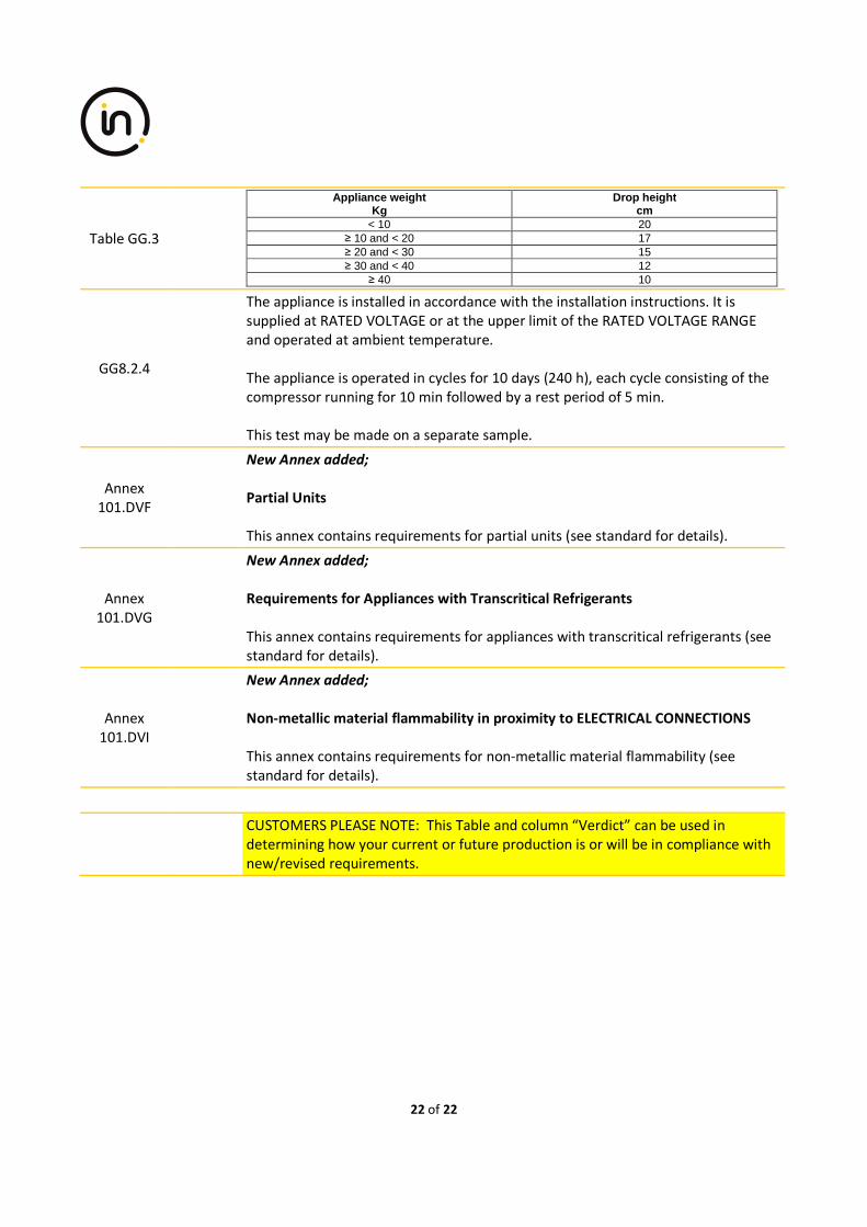
22 of 22
Table GG.3
Appliance weight Kg
Drop height cm
< 10 20 ≥ 10 and < 20 17 ≥ 20 and < 30 15 ≥ 30 and < 40 12
≥ 40 10
GG8.2.4
The appliance is installed in accordance with the installation instructions. It is
supplied at RATED VOLTAGE or at the upper limit of the RATED VOLTAGE RANGE
and operated at ambient temperature.
The appliance is operated in cycles for 10 days (240 h), each cycle consisting of the
compressor running for 10 min followed by a rest period of 5 min.
This test may be made on a separate sample.
Annex
101.DVF
New Annex added;
Partial Units
This annex contains requirements for partial units (see standard for details).
Annex
101.DVG
New Annex added;
Requirements for Appliances with Transcritical Refrigerants
This annex contains requirements for appliances with transcritical refrigerants (see
standard for details).
Annex
101.DVI
New Annex added;
Non-metallic material flammability in proximity to ELECTRICAL CONNECTIONS
This annex contains requirements for non-metallic material flammability (see
standard for details).
CUSTOMERS PLEASE NOTE: This Table and column “Verdict” can be used in
determining how your current or future production is or will be in compliance with
new/revised requirements.