standard zigzag maneuver simulations in calm water and...
TRANSCRIPT

Standard Zigzag Maneuver Simulations in Calm Water and Waves with Direct Propeller and Rudder
Jianhua, Wang1, Decheng, Wan1*, Xinguo Yu2
1 Collaborative Innovation Center for Advanced Ship and Deep-Sea Exploration, State Key Laboratory of Ocean Engineering, School of Naval Architecture, Ocean and Civil Engineering, Shanghai Jiao Tong University, Shanghai, China
2 China Ship Development and Design Center, Shanghai Branch, China *Corresponding author
ABSTRACT In the present work, numerical simulations of standard zigzag maneuver in both calm water and waves are performed. The fully appended ONR Tumblehome model is applied for all the numerical calculations. In-house CFD solver naoe-FOAM-SJTU is used for the direct computations of free running ship model with rotating propellers and moving rudders. Dynamic overset grid method is applied to handle with the complex ship motions with propellers and rudders. OpenFOAM’s third party library waves2Foam is used for the wave generation. Standard 10/10 zigzag maneuver at the approaching speed of Fr=0.2 in calm water and regular head waves are simulated. Ship motions, speeds, propulsion forces and main parameters of standard zigzag maneuver are obtained and compared with the available experimental measurements. Furthermore, flow visualizations are presented for better understanding of the hydrodynamic performance during zigzag motion. Satisfactory agreements are achieved and indicate that the present CFD method with overset grid technology is feasible for the direct simulation of zigzag maneuver in both calm water and waves. KEY WORDS: standard zigzag maneuver; overset grid method; naoe-FOAM-SJTU solver; actual propeller and rudder INTRODUCTION Ship maneuvering is closely related to the navigational safety and this concept lead to the IMO criteria (2002) for ship maneuvering performance. Thus how to accurately predict the ship maneuvering capabilities at the design stage is of great importance. Among several approaches to predict ship maneuverability, direct simulation of free running ship model with rotating propellers and moving rudders is the most accurate way to reappear the real flow field during ship maneuvering motion. However, great challenges show up with the complexity of the flow field and interaction between hull, moving rudders and rotating propellers. When dealing with the fully appended ship, the vortical structures separated from the hull and appendages are even more complicated. For most simulations in ship hydrodynamics,
the 6 degrees of freedom (6DoF) motion is always simplified into 3DoF (roll, heave and pitch) or 2DoF (heave and pitch), which is enough to handle ship resistance, seakeeping problems (Bhushan et al., 2009). But for free running ship maneuver, i.e. turning circle maneuver and zigzag maneuver, the ship needs full 6DoF motion with active rudders and rotating propellers in a free surface condition. All the above aspects increase the difficulty in the study of the free maneuvering problems. With the boosting of high performance computers and development of numerical schemes, tremendous advances have been made in the development of Computational Fluid Dynamics (CFD) on ship hydrodynamics. Besides, the dynamic overset grid technology, including full 6DoF motion with a hierarchy of bodies that enable computation of complex motions of ship hull-propeller-rudder, makes it possible to directly compute ship maneuvering with rotating propellers and moving rudders. Nowadays, overset grid method has been successfully applied to the computations of ship hydrodynamics, especially for the direct simulation of hull-propeller-rudder interaction. Mofidi and Carrica (2014) presented the direct simulations of zigzag maneuver for a container ship, where standard 10/10 zigzag maneuver and 15/1 modified zigzag maneuver are computed. Good agreement to the experiment is achieved and he also emphasizes that the computational cost in direct calculating free running ships is still very high. Broglia et al. (2015) and Dubbioso et al. (2016) took the same approach to simulate the turning circle maneuver of a fully appended twin screw vessel using a finite volume method CFD solver. Further analysis for the distribution of forces and moments on the hull, appendages and rudders has been done to obtain the hydrodynamic behavior in turning tests. Shen et al. (2015) implemented dynamic overset grid module to OpenFOAM and applied to the KCS self-propulsion and zigzag maneuver simulation. Predicted results show good agreements with the experimental data, which show that the fully discretized model with overset grid method is feasible even for the relatively coarse unstructured grids. Wang et al. (2016) used the same method to simulate the full 6DoF self-propulsion and turning circle maneuver of the ONR Tumblehome model in calm water, and the predicted ship motions for the maneuvering conditions agree well with the available experimental data.
1042
Proceedings of the Twenty-seventh (2017) International Ocean and Polar Engineering ConferenceSan Francisco, CA, USA, June 25-30, 2017Copyright © 2017 by the International Society of Offshore and Polar Engineers (ISOPE)ISBN 978-1-880653-97-5; ISSN 1098-6189
www.isope.org

Previous studies on ship maneuvering with free running ship models are mostly done in calm water conditions. Simulation of ship maneuvering in waves requires the capabilities of handling large amplitude ship motions in a violent free surface compared with the calm water states and is also more complicated. In this paper, an incompressible RANS approach with dynamic overset grid technology is applied to direct simulate standard zigzag maneuver of fully appended ONR Tumblehome ship model in both calm water and regular head waves. The outline of this paper goes as follows: first, a brief introduction is given; and the second section presents the numerical approach, where the naoe-FOAM-SJTU solver, dynamic overset grid method and wave generation will be described in detail; the third part is the geometry and simulation design, including the geometry model, grid distribution and test conditions; then comes the simulation results and analysis section; finally, the conclusions of this study are summarized. NUMERICAL APPROACH naoe-FOAM-SJTU Solver The computations are performed with the CFD solver naoe-FOAM-SJTU, which is developed on the open source platform OpenFOAM. The framework of naoe-FOAM-SJTU solver and its main features are only briefly presented here; more details can be referred to Shen et al. (2015; 2016) and Cao et al. (2014, 2015). The solver has overset grid capability and is mainly composed of a velocity inlet wave-making module, a full 6DoF module with a hierarchy of bodies and a mooring system module. The present CFD code solves the Reynolds-averaged Navier-Stokes (RANS) equations for unsteady turbulent flows around the complex geometry models. The turbulence is modeled by a blended
/k kω ε− − shear stress transport (Menter et al., 2003) turbulence model and near wall treatment is using the wall functions. The methodology uses a VOF approach with bounded compression technique (Weller, 2008) to capture free surface. Finite volume method (FVM) with fully unstructured grids is used to transform the RANS and VOF equations from physical space into computational space. The solution of the governing equations is achieved by using the pressure-implicit split-operator (PISO) algorithm (Issa, 1986). In addition, several built-in numerical schemes in OpenFOAM are used to solve the partial differential equations (PDE). The second order backward Euler scheme is used for temporal discretization. Second order TVD scheme is used to discretize the convection term, while a central differencing scheme is applied for diffusion terms. Overset Grid Method The overset grid method plays an important role in direct computing the complex ship motions with rotating propeller and moving rudder. Thus, a brief introduction of the utilization of overset grid module in naoe-FOAM-SJTU solver is presented. Overset grid is made up of two or more blocks of overlapping structured or unstructured grids. By using dynamic overset grid techniques, the overlapping grids can move independently without constraints. In the dynamic overset computation process, the grids in the computational domain are first classified into several types according to their location, such as fringe cells, hole cells, donor cells etc. Fringe cell has a stencil consisting of several donor cells that provide information to it from the donor grid. The information of overset grids is contained in the domain connectivity information (DCI) file. In the present solver, Suggar++ (Noack et al.,
2009) is utilized to generate the domain connectivity information (DCI) for the overset grid interpolation. To combine OpenFOAM with Suggar++, a communication, which is responsible for DCI exchange between OpenFOAM and Suggar++, has been implemented using the Message passing interface (MPI) library (Shen et al., 2015). Other features consist of a full 6DoF motion module with a hierarchy moving components and several modifications for sparse matrix solvers and MULES solver to excluded non-active cells (hole cells). With the dynamic overset grid capability, the full 6DoF motion solver allows the ship hull as well as the moving components to move simultaneously. Details of the full 6DoF motion with overset grid module implementation can be found in Shen et al., (2015). In our present study, the complex geometry is decomposed into several overlapping grids, which can be used to direct simulate free running ship maneuver. Wave Generation In the present work, an open source toolbox waves2Foam (Jacobsen et al., 2012), OpenFOAM’s third party library, is used to generate desired regular waves. The methodology uses a relaxation factor to blend the far field analytic solution with the near field computed value. In addition, the wave generation zone (relaxation zone) can also be fixed with a certain area of the computational domain (frozen type), which can be applied to the moving wave generation zone along with the computational domain during zigzag simulation. Detailed wave generation zone and computational domain is shown in Fig. 1.
Fig. 1 Wave generation zone and computational domain GEOMETRY AND SIMULATION DESIGN Geometry Model The surface combatant, ONR Tumblehome model 5613, is applied for the standard zigzag maneuver simulation. The ship model is fully appended with skeg and bilge keels as well as rudders, shafts and propellers with propeller shaft brackets. It is used as one of the benchmark ship models for CFD validation in Tokyo 2015 CFD workshop on ship hydrodynamics. The geometry of ONR Tumblehome is shown in Fig. 2.
Fig. 2 Geometry of ONR Tumblehome ship model
1043
The main particulars of the fully appended ONR Tumblehome ship model are listed in Table 1. Table 1 Main particulars of ONR Tumblehome ship model
Main particulars Model scale Full scaleLength of waterline ( )WLL m 3.147 154.0 Beam of waterline ( )WLB m 0.384 18.78 Draft ( )T m 0.112 5.494 Displacement ( )kgΔ 72.6 8.507e6 Propeller diameter ( )PD m 0.1066 NA Propeller shaft angle ε (deg.) 5 NA Propeller rotation inward inward Rudder rate 35.0 deg./s
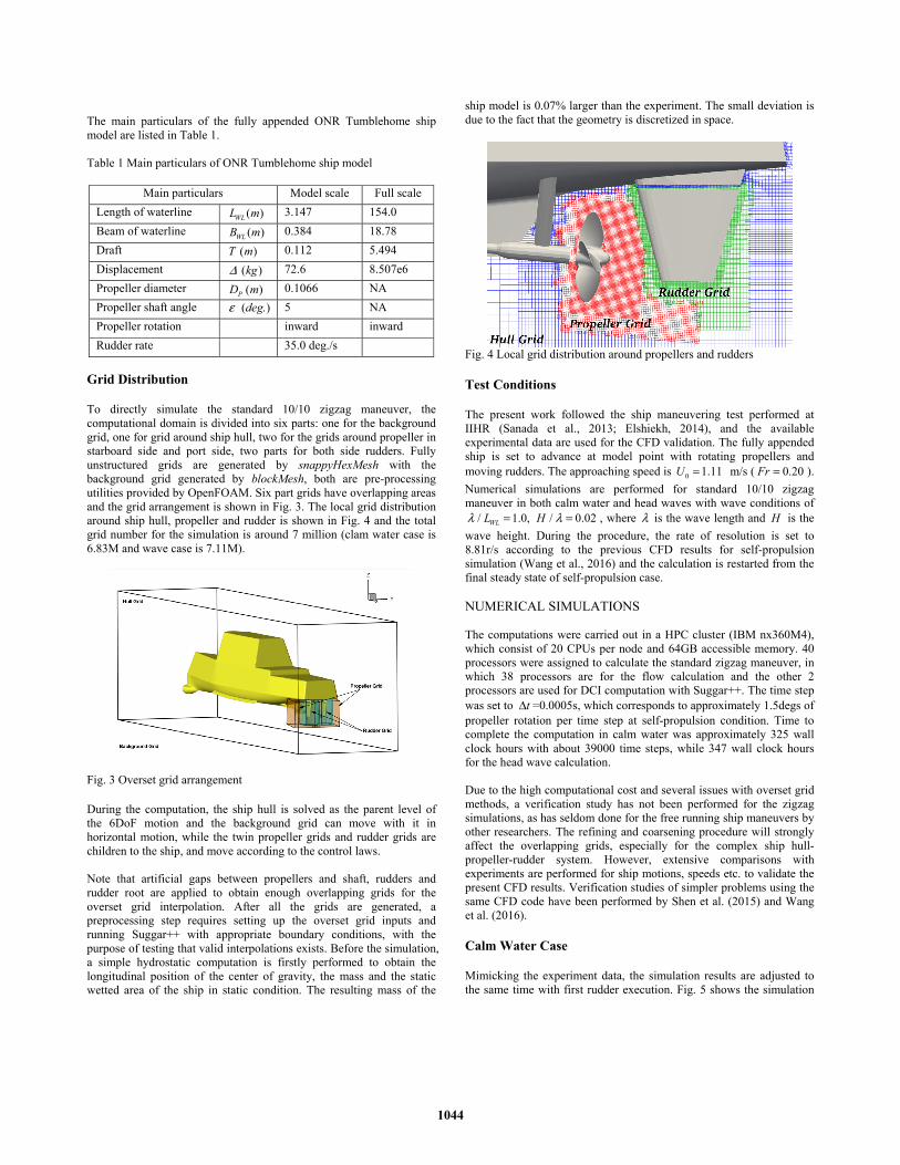
Grid Distribution To directly simulate the standard 10/10 zigzag maneuver, the computational domain is divided into six parts: one for the background grid, one for grid around ship hull, two for the grids around propeller in starboard side and port side, two parts for both side rudders. Fully unstructured grids are generated by snappyHexMesh with the background grid generated by blockMesh, both are pre-processing utilities provided by OpenFOAM. Six part grids have overlapping areas and the grid arrangement is shown in Fig. 3. The local grid distribution around ship hull, propeller and rudder is shown in Fig. 4 and the total grid number for the simulation is around 7 million (clam water case is 6.83M and wave case is 7.11M).
Fig. 3 Overset grid arrangement During the computation, the ship hull is solved as the parent level of the 6DoF motion and the background grid can move with it in horizontal motion, while the twin propeller grids and rudder grids are children to the ship, and move according to the control laws. Note that artificial gaps between propellers and shaft, rudders and rudder root are applied to obtain enough overlapping grids for the overset grid interpolation. After all the grids are generated, a preprocessing step requires setting up the overset grid inputs and running Suggar++ with appropriate boundary conditions, with the purpose of testing that valid interpolations exists. Before the simulation, a simple hydrostatic computation is firstly performed to obtain the longitudinal position of the center of gravity, the mass and the static wetted area of the ship in static condition. The resulting mass of the
ship model is 0.07% larger than the experiment. The small deviation is due to the fact that the geometry is discretized in space.
Fig. 4 Local grid distribution around propellers and rudders Test Conditions The present work followed the ship maneuvering test performed at IIHR (Sanada et al., 2013; Elshiekh, 2014), and the available experimental data are used for the CFD validation. The fully appended ship is set to advance at model point with rotating propellers and moving rudders. The approaching speed is 0 1.11U = m/s ( 0.20Fr = ). Numerical simulations are performed for standard 10/10 zigzag maneuver in both calm water and head waves with wave conditions of
/ 1.0, / 0.02WLL Hλ λ= = , where λ is the wave length and H is the wave height. During the procedure, the rate of resolution is set to 8.81r/s according to the previous CFD results for self-propulsion simulation (Wang et al., 2016) and the calculation is restarted from the final steady state of self-propulsion case. NUMERICAL SIMULATIONS The computations were carried out in a HPC cluster (IBM nx360M4), which consist of 20 CPUs per node and 64GB accessible memory. 40 processors were assigned to calculate the standard zigzag maneuver, in which 38 processors are for the flow calculation and the other 2 processors are used for DCI computation with Suggar++. The time step was set to tΔ =0.0005s, which corresponds to approximately 1.5degs of propeller rotation per time step at self-propulsion condition. Time to complete the computation in calm water was approximately 325 wall clock hours with about 39000 time steps, while 347 wall clock hours for the head wave calculation. Due to the high computational cost and several issues with overset grid methods, a verification study has not been performed for the zigzag simulations, as has seldom done for the free running ship maneuvers by other researchers. The refining and coarsening procedure will strongly affect the overlapping grids, especially for the complex ship hull-propeller-rudder system. However, extensive comparisons with experiments are performed for ship motions, speeds etc. to validate the present CFD results. Verification studies of simpler problems using the same CFD code have been performed by Shen et al. (2015) and Wang et al. (2016). Calm Water Case Mimicking the experiment data, the simulation results are adjusted to the same time with first rudder execution. Fig. 5 shows the simulation
1044
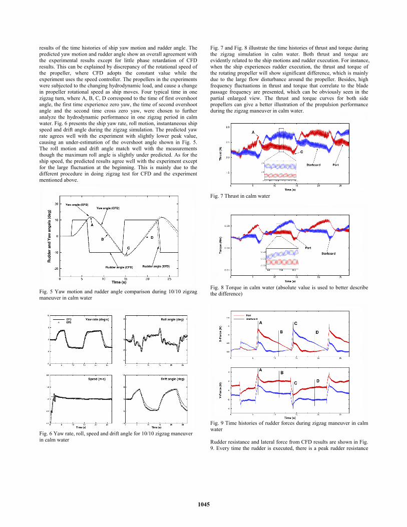
results of the time histories of ship yaw motion and rudder angle. The predicted yaw motion and rudder angle show an overall agreement with the experimental results except for little phase retardation of CFD results. This can be explained by discrepancy of the rotational speed of the propeller, where CFD adopts the constant value while the experiment uses the speed controller. The propellers in the experiments were subjected to the changing hydrodynamic load, and cause a change in propeller rotational speed as ship moves. Four typical time in one zigzag turn, where A, B, C, D correspond to the time of first overshoot angle, the first time experience zero yaw, the time of second overshoot angle and the second time cross zero yaw, were chosen to further analyze the hydrodynamic performance in one zigzag period in calm water. Fig. 6 presents the ship yaw rate, roll motion, instantaneous ship speed and drift angle during the zigzag simulation. The predicted yaw rate agrees well with the experiment with slightly lower peak value, causing an under-estimation of the overshoot angle shown in Fig. 5. The roll motion and drift angle match well with the measurements though the maximum roll angle is slightly under predicted. As for the ship speed, the predicted results agree well with the experiment except for the large fluctuation at the beginning. This is mainly due to the different procedure in doing zigzag test for CFD and the experiment mentioned above.
Fig. 5 Yaw motion and rudder angle comparison during 10/10 zigzag maneuver in calm water
Fig. 6 Yaw rate, roll, speed and drift angle for 10/10 zigzag maneuver in calm water
Fig. 7 and Fig. 8 illustrate the time histories of thrust and torque during the zigzag simulation in calm water. Both thrust and torque are evidently related to the ship motions and rudder execution. For instance, when the ship experiences rudder execution, the thrust and torque of the rotating propeller will show significant difference, which is mainly due to the large flow disturbance around the propeller. Besides, high frequency fluctuations in thrust and torque that correlate to the blade passage frequency are presented, which can be obviously seen in the partial enlarged view. The thrust and torque curves for both side propellers can give a better illustration of the propulsion performance during the zigzag maneuver in calm water.
Fig. 7 Thrust in calm water
Fig. 8 Torque in calm water (absolute value is used to better describe the difference)
Fig. 9 Time histories of rudder forces during zigzag maneuver in calm water Rudder resistance and lateral force from CFD results are shown in Fig. 9. Every time the rudder is executed, there is a peak rudder resistance
1045
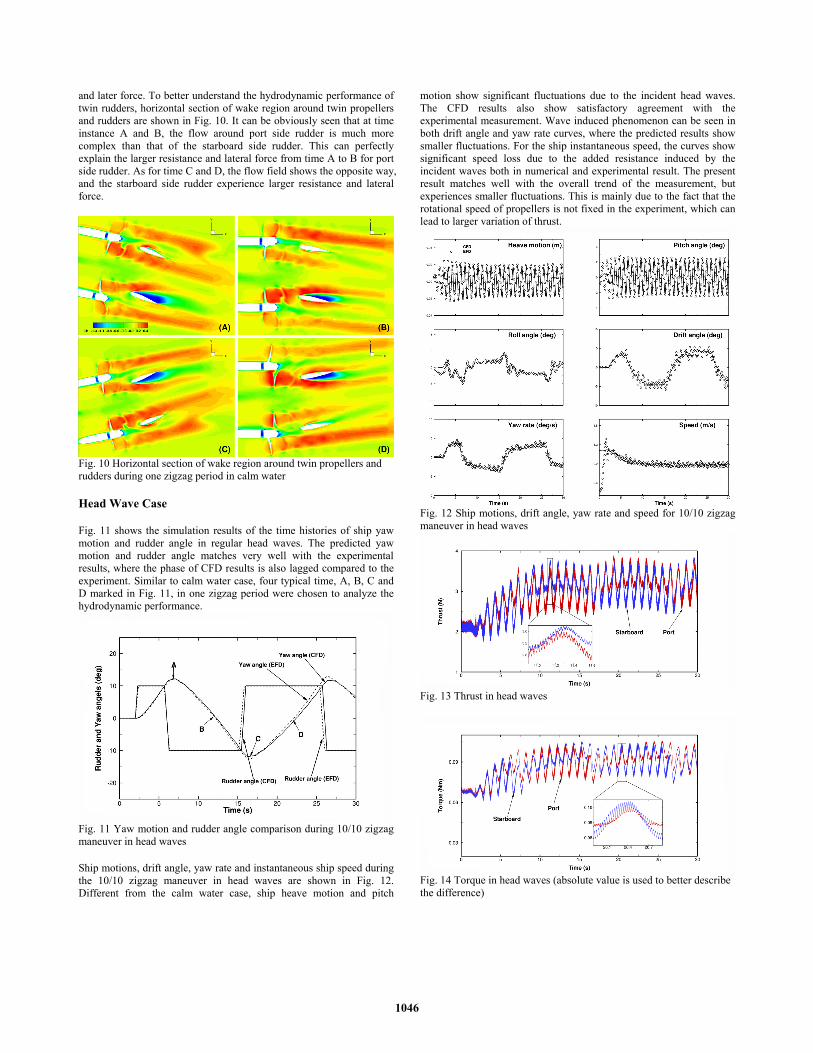
and later force. To better understand the hydrodynamic performance of twin rudders, horizontal section of wake region around twin propellers and rudders are shown in Fig. 10. It can be obviously seen that at time instance A and B, the flow around port side rudder is much more complex than that of the starboard side rudder. This can perfectly explain the larger resistance and lateral force from time A to B for port side rudder. As for time C and D, the flow field shows the opposite way, and the starboard side rudder experience larger resistance and lateral force.
Fig. 10 Horizontal section of wake region around twin propellers and rudders during one zigzag period in calm water Head Wave Case Fig. 11 shows the simulation results of the time histories of ship yaw motion and rudder angle in regular head waves. The predicted yaw motion and rudder angle matches very well with the experimental results, where the phase of CFD results is also lagged compared to the experiment. Similar to calm water case, four typical time, A, B, C and D marked in Fig. 11, in one zigzag period were chosen to analyze the hydrodynamic performance.
Fig. 11 Yaw motion and rudder angle comparison during 10/10 zigzag maneuver in head waves Ship motions, drift angle, yaw rate and instantaneous ship speed during the 10/10 zigzag maneuver in head waves are shown in Fig. 12. Different from the calm water case, ship heave motion and pitch
motion show significant fluctuations due to the incident head waves. The CFD results also show satisfactory agreement with the experimental measurement. Wave induced phenomenon can be seen in both drift angle and yaw rate curves, where the predicted results show smaller fluctuations. For the ship instantaneous speed, the curves show significant speed loss due to the added resistance induced by the incident waves both in numerical and experimental result. The present result matches well with the overall trend of the measurement, but experiences smaller fluctuations. This is mainly due to the fact that the rotational speed of propellers is not fixed in the experiment, which can lead to larger variation of thrust.
Fig. 12 Ship motions, drift angle, yaw rate and speed for 10/10 zigzag maneuver in head waves
Fig. 13 Thrust in head waves
Fig. 14 Torque in head waves (absolute value is used to better describe the difference)
1046

Thrust and torque of the twin propellers during zigzag simulation in head waves are shown in Fig. 13 and Fig. 14, respectively. Both propulsion parameters are evidently related to the time evolution of ship motions. Due to the incident head waves, the thrust and torque curves show significant fluctuations with wave frequency and the amplitude is much larger. High frequency fluctuations in thrust and torque that correlate to the blade passage frequency can also be captured, which can be seen in the partial enlarged view. Strong wave effect can be observed for the zigzag maneuver in wave conditions and both curves give a detailed description of the propulsion performance during the zigzag motion in head waves.
Fig. 15 Time histories of rudder force during zigzag maneuver in head waves
Fig. 16 Horizontal section of wake region around twin propellers and rudders during one zigzag period in head waves Rudder resistance and lateral force for both sides are depicted in Fig. 15. Compared with the calm water case, the rudder forces experience the same trend but with significant wave induced fluctuations. The force amplitude excited by the waves can as large as the force due to rudder execution, which indicates that the wave effect is of great importance during the zigzag motion. To analyze the rudder behavior, horizontal
section of wake region around twin propellers and rudders are presented in Fig. 16. Different from the calm water case, both side rudders experience much more complex flows and this can explain the large fluctuation during the most simulation time. In addition, the wake region can also illustrate the inflow variation during one zigzag period. For instance, at time A, the inflow of the twin propellers is smaller than that of time C, this will further lead to larger thrust at time A. Through the flow visualizations, the hydrodynamic performance can be better understood, thus CFD is becoming an undeniably attractive tool for the numerical analysis and visualizations of the flow field. Fig. 17 shows the wave elevation during one zigzag period in head waves. It can be seen that the wave diffraction is considerable and wave patterns are strongly related to the zigzag motion. When the ship experiencing maximum yaw to port side and starboard side, the diffraction wave extend to a wide area with strong asymmetry flow around ship hull, which will further cause a significant lateral force and yaw moment. Bow wave breaking phenomenon can also be observed at time instance C. Free surface elevation describes the detailed wave hull interaction and can used to analyze the ship motions with zigzag motion in head waves.
Fig. 17 Free surface elevation during one zigzag period in head waves Zigzag Parameters To evaluate the ship maneuverability, main parameters for zigzag tests are listed in Table 2. The overshoot angle (OSA) characterize the excess angle between the maximum ship’s heading and the check heading angle, and the period is the time to complete a cycle. The present CFD results matches very well with the EFD data for the zigzag parameters. Both CFD and experiment data show that the zigzag maneuver in waves experience longer time to complete a cycle. This is due to the significant speed loss in head waves, and result in the longer period to complete the zigzag motion. For this case, results can be compared against International Maritime Organization (IMO) standards. According to the standards for the twin rudders, the first overshoot angle needs to be less than 10 degs, both CFD and EFD results satisfies this criteria. As for the standards for second overshoot angle, 25 degs can also be satisfied with the present results. High accurate predicted results indicates that the present solver naoe-FOAM-SJTU coupled with dynamic overset grid method is feasible to simulate standard zigzag maneuver in both calm water and waves.
1047
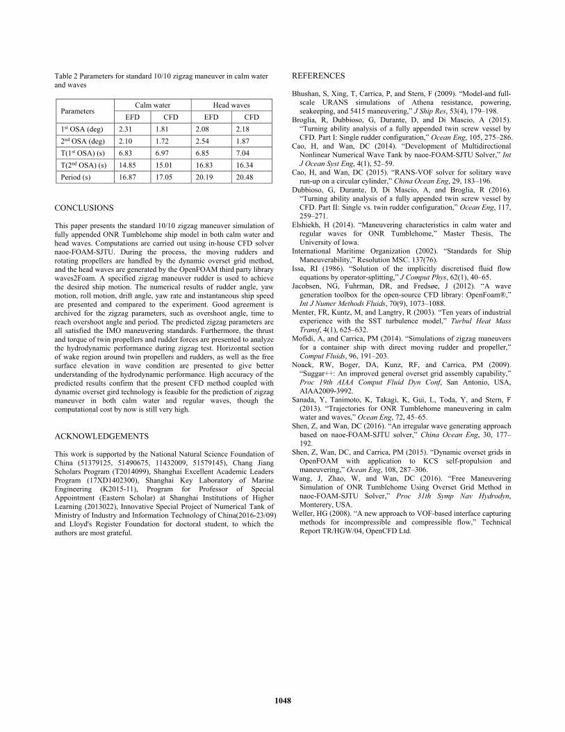
Table 2 Parameters for standard 10/10 zigzag maneuver in calm water and waves
Parameters Calm water Head waves
EFD CFD EFD CFD 1st OSA (deg) 2.31 1.81 2.08 2.18 2nd OSA (deg) 2.10 1.72 2.54 1.87 T(1st OSA) (s) 6.83 6.97 6.85 7.04 T(2nd OSA) (s) 14.85 15.01 16.83 16.34 Period (s) 16.87 17.05 20.19 20.48
CONCLUSIONS This paper presents the standard 10/10 zigzag maneuver simulation of fully appended ONR Tumblehome ship model in both calm water and head waves. Computations are carried out using in-house CFD solver naoe-FOAM-SJTU. During the process, the moving rudders and rotating propellers are handled by the dynamic overset grid method, and the head waves are generated by the OpenFOAM third party library waves2Foam. A specified zigzag maneuver rudder is used to achieve the desired ship motion. The numerical results of rudder angle, yaw motion, roll motion, drift angle, yaw rate and instantaneous ship speed are presented and compared to the experiment. Good agreement is archived for the zigzag parameters, such as overshoot angle, time to reach overshoot angle and period. The predicted zigzag parameters are all satisfied the IMO maneuvering standards. Furthermore, the thrust and torque of twin propellers and rudder forces are presented to analyze the hydrodynamic performance during zigzag test. Horizontal section of wake region around twin propellers and rudders, as well as the free surface elevation in wave condition are presented to give better understanding of the hydrodynamic performance. High accuracy of the predicted results confirm that the present CFD method coupled with dynamic overset gird technology is feasible for the prediction of zigzag maneuver in both calm water and regular waves, though the computational cost by now is still very high. ACKNOWLEDGEMENTS This work is supported by the National Natural Science Foundation of China (51379125, 51490675, 11432009, 51579145), Chang Jiang Scholars Program (T2014099), Shanghai Excellent Academic Leaders Program (17XD1402300), Shanghai Key Laboratory of Marine Engineering (K2015-11), Program for Professor of Special Appointment (Eastern Scholar) at Shanghai Institutions of Higher Learning (2013022), Innovative Special Project of Numerical Tank of Ministry of Industry and Information Technology of China(2016-23/09) and Lloyd's Register Foundation for doctoral student, to which the authors are most grateful.
REFERENCES Bhushan, S, Xing, T, Carrica, P, and Stern, F (2009). “Model-and full-
scale URANS simulations of Athena resistance, powering, seakeeping, and 5415 maneuvering,” J Ship Res, 53(4), 179–198.
Broglia, R, Dubbioso, G, Durante, D, and Di Mascio, A (2015). “Turning ability analysis of a fully appended twin screw vessel by CFD. Part I: Single rudder configuration,” Ocean Eng, 105, 275–286.
Cao, H, and Wan, DC (2014). “Development of Multidirectional Nonlinear Numerical Wave Tank by naoe-FOAM-SJTU Solver,” Int J Ocean Syst Eng, 4(1), 52–59.
Cao, H, and Wan, DC (2015). “RANS-VOF solver for solitary wave run-up on a circular cylinder,” China Ocean Eng, 29, 183–196.
Dubbioso, G, Durante, D, Di Mascio, A, and Broglia, R (2016). “Turning ability analysis of a fully appended twin screw vessel by CFD. Part II: Single vs. twin rudder configuration,” Ocean Eng, 117, 259–271.
Elshiekh, H (2014). “Maneuvering characteristics in calm water and regular waves for ONR Tumblehome,” Master Thesis, The University of Iowa.
International Maritime Organization (2002). “Standards for Ship Maneuverability,” Resolution MSC. 137(76).
Issa, RI (1986). “Solution of the implicitly discretised fluid flow equations by operator-splitting,” J Comput Phys, 62(1), 40–65.
Jacobsen, NG, Fuhrman, DR, and Fredsøe, J (2012). “A wave generation toolbox for the open-source CFD library: OpenFoam®,” Int J Numer Methods Fluids, 70(9), 1073–1088.
Menter, FR, Kuntz, M, and Langtry, R (2003). “Ten years of industrial experience with the SST turbulence model,” Turbul Heat Mass Transf, 4(1), 625–632.
Mofidi, A, and Carrica, PM (2014). “Simulations of zigzag maneuvers for a container ship with direct moving rudder and propeller,” Comput Fluids, 96, 191–203.
Noack, RW, Boger, DA, Kunz, RF, and Carrica, PM (2009). “Suggar++: An improved general overset grid assembly capability,” Proc 19th AIAA Comput Fluid Dyn Conf, San Antonio, USA, AIAA2009-3992.
Sanada, Y, Tanimoto, K, Takagi, K, Gui, L, Toda, Y, and Stern, F (2013). “Trajectories for ONR Tumblehome maneuvering in calm water and waves,” Ocean Eng, 72, 45–65.
Shen, Z, and Wan, DC (2016). “An irregular wave generating approach based on naoe-FOAM-SJTU solver,” China Ocean Eng, 30, 177–192.
Shen, Z, Wan, DC, and Carrica, PM (2015). “Dynamic overset grids in OpenFOAM with application to KCS self-propulsion and maneuvering,” Ocean Eng, 108, 287–306.
Wang, J, Zhao, W, and Wan, DC (2016). “Free Maneuvering Simulation of ONR Tumblehome Using Overset Grid Method in naoe-FOAM-SJTU Solver,” Proc 31th Symp Nav Hydrodyn, Monterery, USA.
Weller, HG (2008). “A new approach to VOF-based interface capturing methods for incompressible and compressible flow,” Technical Report TR/HGW/04, OpenCFD Ltd.
1048