standard practice for mechanized ultrasonic testing of
TRANSCRIPT

Designation: E1961 − 16
Standard Practice forMechanized Ultrasonic Testing of Girth Welds Using ZonalDiscrimination with Focused Search Units1
This standard is issued under the fixed designation E1961; the number immediately following the designation indicates the year oforiginal adoption or, in the case of revision, the year of last revision. A number in parentheses indicates the year of last reapproval. Asuperscript epsilon (´) indicates an editorial change since the last revision or reapproval.
1. Scope*
1.1 This practice covers the requirements for mechanizedultrasonic examination of girth welds. Evaluation is basedupon the results of mechanized ultrasonic examination. Accep-tance criteria are based upon flaw limits defined by anEngineering Critical Assessment (ECA) or other accept/rejectcriteria defined by the Contracting Agency.
1.2 This practice shall be applicable to the development ofan examination procedure agreed upon between the users ofthis practice.
1.3 The values stated in SI units are to be regarded as thestandard. The inch-pound units given in parentheses are forinformation only.
1.4 This standard does not purport to address all of thesafety concerns, if any, associated with its use. It is theresponsibility of the user of this standard to establish appro-priate safety and health practices and determine the applica-bility of regulatory limitations prior to use.
2. Referenced Documents
2.1 The following documents form a part of this practice tothe extent specified herein:
2.2 ASTM Standards:2
E164 Practice for Contact Ultrasonic Testing of WeldmentsE317 Practice for Evaluating Performance Characteristics of
Ultrasonic Pulse-Echo Testing Instruments and Systemswithout the Use of Electronic Measurement Instruments
E543 Specification for Agencies Performing NondestructiveTesting
E1316 Terminology for Nondestructive Examinations
2.3 ASNT Standard:3
ASNT Practice SNT-TC-1A Personnel Qualification andCertification in Nondestructive Testing
ANSI/ASNT-CP-189 Standard for Qualification and Certifi-cation of Nondestructive Testing Personnel
2.4 AIA Standard:NAS-410 Nondestructive Testing Personnel Qualification
and Certification4
2.5 API Standard:API STD–1104 Welding of Pipeline and Related Facilities5
2.6 CSA Standard:CSA Z-662 Oil and Gas Pipelines Systems6
2.7 ISO Standards7
ISO 9712 Nondestructive Testing—Qualification and Certi-fication of NDT Personnel
3. Terminology
3.1 Definitions:3.1.1 Definitions relating to ultrasonic examination, that
appear in Terminology E1316 shall apply to the terms used inthis practice.
3.2 Definitions of Terms Specific to This Standard:3.2.1 acceptance criteria—definition of acceptable/
rejectable flaws as defined by an Engineering Critical Assess-ment (ECA), such as defined in CSA-Z662 or API 1104, orworkmanship criteria as defined by the contracting agency.
3.2.2 contract document—any document specified in thecontract between the contracting agency and contractor, includ-ing the purchase order, specification, drawings or other writtenmaterial.
1 This practice is under the jurisdiction of ASTM Committee E07 on Nonde-structive Testing and is the direct responsibility of Subcommittee E07.06 onUltrasonic Method.
Current edition approved June 1, 2016. Published June 2016. Originallyapproved in 1998. Last previous edition approved in 2011 as E1961 - 11. DOI:10.1520/E1961-16.
2 For referenced ASTM standards, visit the ASTM website, www.astm.org, orcontact ASTM Customer Service at [email protected]. For Annual Book of ASTMStandards volume information, refer to the standard’s Document Summary page onthe ASTM website.
3 Available from American Society for Nondestructive Testing (ASNT), P.O. Box28518, 1711 Arlingate Ln., Columbus, OH 43228-0518, http://www.asnt.org.
4 Available from Aerospace Industries Association of America, Inc. (AIA), 1000Wilson Blvd., Suite 1700, Arlington, VA 22209-3928, http://www.aia-aerospace.org.
5 Available from American Petroleum Institute (API), 1220 L. St., NW,Washington, DC 20005-4070, http://www.api.org.
6 Available from Canadian Standards Association (CSA), 5060 Spectrum Way,Mississauga, ON L4W 5N6, Canada, http://www.csa.ca.
7 Available from International Organization for Standardization (ISO), ISOCentral Secretariat, BIBC II, Chemin de Blandonnet 8, CP 401, 1214 Vernier,Geneva, Switzerland, http://www.iso.org.
*A Summary of Changes section appears at the end of this standard
Copyright © ASTM International, 100 Barr Harbor Drive, PO Box C700, West Conshohocken, PA 19428-2959. United States
1
3.2.3 contracting agency—a government agency, primecontractor or subcontractor procuring ultrasonic examinationservices.
3.2.4 contractor—the nondestructive examination contrac-tor engaged by the contracting agency in work covered by thispractice.
3.2.5 mapping type presentations—an ultrasonic image pre-sentation whereby the digitized A-scan signal is represented ascolors or grayscale for amplitude variation along one axisrepresenting time of flight and the other axis is the samplingposition, or the distance along the weld.
3.2.6 operator(s)—the term “operator(s)” as used in thispractice shall mean the operator(s) of ultrasonic equipmentwho is (are) certified according to the requirements in 5.2 andat a level deemed acceptable to the contracting agency.
4. Significance and Use
4.1 This practice is intended primarily for the mechanizedultrasonic examination of pipe girth welds used in the con-struction of gas and oil pipelines. This practice, with appropri-ate modifications due to changes in weld profile, may also beused to examine repaired welds. Manual techniques such asdescribed in Practice E164 may also be used to examineproduction or repaired welds. This practice, with appropriatemodifications, may also be used to examine other forms of buttwelds including long seams.
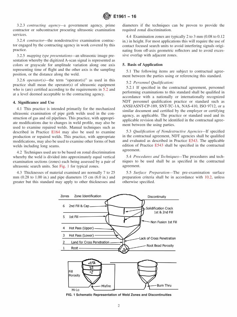
4.2 Techniques used are to be based on zonal discriminationwhereby the weld is divided into approximately equal verticalexamination sections (zones) each being assessed by a pair ofultrasonic search units. See Fig. 1 for typical zones.
4.3 Thicknesses of material examined are normally 7 to 25mm (0.28 to 1.00 in.) and pipe diameters 15 cm (6.0 in.) andgreater but this standard may apply to other thicknesses and
diameters if the techniques can be proven to provide therequired zonal discrimination.
4.4 Examination zones are typically 2 to 3 mm (0.08 to 0.12in.) in height. For most applications this will require the use ofcontact focused search units to avoid interfering signals origi-nating from off-axis geometric reflectors and to avoid exces-sive overlap with adjacent zones.
5. Basis of Application
5.1 The following items are subject to contractual agree-ment between the parties using or referencing this standard.
5.2 Personnel Qualification:5.2.1 If specified in the contractual agreement, personnel
performing examinations to this standard shall be qualified inaccordance with a nationally or internationally recognizedNDT personnel qualification practice or standard such asANSI/ASNT-CP-189, SNT-TC-1A, NAS-410, ISO 9712, or asimilar document and certified by the employer or certifyingagency, as applicable. The practice or standard used and itsapplicable revision shall be identified in the contractual agree-ment between the using parties.
5.3 Qualification of Nondestructive Agencies—If specifiedin the contractual agreement, NDT agencies shall be qualifiedand evaluated as described in Practice E543. The applicableedition of Practice E543 shall be specified in the contractualagreement.
5.4 Procedures and Techniques—The procedures and tech-niques to be used shall be as specified in the contractualagreement.
5.5 Surface Preparation—The pre-examination surfacepreparation criteria shall be in accordance with 10.2, unlessotherwise specified.
FIG. 1 Schematic Representation of Weld Zones and Discontinuities
E1961 − 16
2
5.6 Timing of Examination—The timing of examinationshall be in accordance with 10.3, unless otherwise specified.
5.7 Extent of Examination—The extent of examination shallbe in accordance with Section 8, unless otherwise specified.
5.8 Reporting Criteria/Acceptance Criteria—Reporting cri-teria for the examination results shall be in accordance withSection 11, unless otherwise specified. Since acceptance crite-ria are not specified in this standard, they shall be specified inthe contractual agreement.
5.9 Reexamination of Repaired/Reworked Items—Reexamination of repaired/reworked items is not addressed inthis standard and if required shall be specified in the contrac-tual agreement.
6. Examination Methods
6.1 Visual Examination—All welds shall be visually exam-ined after completion and assessed in accordance with therequirements of surface conditions for ultrasonic examination.
6.2 All bevels shall be examined immediately after machin-ing to ensure compliance with the applicable welding proce-dure. This examination should be combined with scribing thereference line as described in 10.4.
6.3 Any items of non-compliance shall be referred to thecontracting agency representative for corrective action.
6.4 Ultrasonic Examination—All girth welds identified formechanized ultrasonic examination shall be examined for100 % of their circumference and assessed in accordance withthe contracting agency’s acceptance criteria. Examinationshould be conducted in accordance with procedures approvedby the contracting agency.
7. Ultrasonic Equipment
7.1 Ultrasonic System—The system shall provide an ad-equate number of examination channels to ensure the completevolumetric examination of the weld through thickness in onecircumferential scan. The instrument shall provide a linear “A”scan presentation for each channel selected. The examinationchannels will allow the volume of the weld scanned to beassessed in accordance with the examination zones as typicallydefined in Fig. 1. Instrument linearity shall be determinedaccording to the procedures detailed in Practice E317, withinsix months of the intended end use date. The contractor shallretain a copy of the calibration certificate. Instrument linearityshall be such that the accuracy of any indicated amplitude iswithin 5 % of the actual full scale amplitude. This shall applyto both linear and logarithmic amplifiers. Each examinationchannel shall be selective for: pulse-echo or through-transmission mode, gate position and length for a minimum oftwo gates, and gain. Recording thresholds shall be selectable todisplay signals between 0 and 100 % of full screen height forsimple amplitude and transit time recording and shall be from0 to 100 % for B-scan or “mapping” type recording of data.Two recordable signal outputs per gate shall be available, beingeither analog or digital and representative of signal height andtime of flight. These will be suitable for recording on amulti-channel recorder or computer data acquisition softwaredisplay.
7.2 Recording System:7.2.1 A distance measuring circuit or device suitable for
connection to the recorder or acquisition system shall providea means of electronically determining circumferential welddistance to an accuracy of typically 61 cm (0.4 in.) or better,as required by the contracting agency, over the circumferenceof the weld (an optical encoder is typically used for suchdistance measurement). Programmed scan lengths shall besufficient to ensure all probes will travel the maximum circum-ferential distance required for a pipe having a diameter with themaximum tolerance allowed by the contracting agency’s speci-fication. For equipment with encoders traveling on a track orwelding guide-band a correction factor will be incorporated toensure the circumferential distance recorded on the chartcorresponds to the search unit position on the pipe outersurface. The recording or marking system shall clearly indicatethe location of discontinuities relative to the marked startingposition of the scan, with a 61 cm (0.4 in.) accuracy. Thereshall be recordings from each search unit for weld discontinui-ties and confirmation of the acoustic coupling arranged on thechart or display in a manner acceptable to the contractingagency.
7.2.2 B-scan or other form of “mapping” displays will beused for volumetric flaw detection and characterizations andTime of Flight Diffraction (TOFD) techniques may be added toimprove characterization and sizing. TOFD techniques mayaugment pulse-echo techniques but shall not replace pulse-echo techniques.
7.2.3 Where TOFD techniques are employed the recordingsystem shall be capable of a 256-level grayscale display and becapable of recording full R-F wave forms for the TOFD searchunit pairs.
7.3 Coupling—The coupling shall be obtained by using amedium suitable for the purpose. An environmentally safewetting agent may be required to enhance acoustic coupling.No residue should remain on the pipe surface after the liquidhas evaporated. For examination where ambient temperaturesare below 0°C (32°F) a methyl alcohol washer fluid or a similarmedium may be used. This liquid medium may be recoveredand filtered for re-use. For examination where pipe cool-downmay be required after welding, water spray or other agents maybe used with contracting agency approval.
7.4 Search Units:7.4.1 Each search unit shall be marked with a method to
identify the manufacturer’s name, search unit type, exit point,incident beam angle or refracted beam angle for a specificwedge/steel velocity ratio, frequency, and crystal size.8
7.4.2 The search unit array design shall be specific to theproject where the examination is to be performed.
7.4.3 All search units shall be contoured to match thecurvature of the pipe surface.
7.5 Reference Standards—Reference standards shall be usedto establish sensitivity and qualify the examination system forfield examination and to monitor the system’s performance on
8 For phased array and EMAT probes, not all of the listed items may beapplicable.
E1961 − 16
3

an ongoing basis. Reference standards shall be manufacturedfrom a section of unflawed project-specific line pipe suppliedby the contracting agency. The contracting agency will providethe contractor with details of project-specific weld geometriesand the reference reflectors required in specific areas. Thecontractor shall then provide a reference standard design thatmust be submitted to the contracting agency for approvalbefore manufacturing. No design changes to the referencestandard shall be made without prior approval of the contract-ing agency. Annex A3 provides an example of a typicalreference standard.
7.6 Ultrasonic Examination Procedure—The contractorshall provide a procedure that will provide examination criteriafor the ultrasonic examination of the weld in a single pass. Itmust allow for characteristic Hi/Lo fit-ups (edgemisalignment), weld shrinkage and be pipe-size specific. Pro-cedures submitted will allow zonal flaw characterization thatpermits use of the contracting agency’s engineering criticalassessment acceptance criteria. It shall include but not belimited to describing the following requirements:
7.6.1 The mechanized variable speed scanner mountable onmechanical welding bands or other tracking mechanism,
7.6.2 The encoder capable of accurately indicating any flawlocation about the girth weld,
7.6.3 Independently loaded ultrasonic search units mountedin an array that provides independent examination of the weldfrom both sides,
7.6.4 Provisions for adjusting and maintaining the align-ment of these search units,
7.6.5 Provisions for recording the continuity of thecoupling,
7.6.6 Provisions for ensuring the mechanical reliability ofthe equipment,
7.6.7 A technique summary stating beam angles, wavetypes, search unit frequencies, beam sizes and profiles withsketches for each geometry to be examined,
7.6.8 Record analog or digital signals from the multi-channels to a common distance of rotation,
7.6.9 Provide permanent copy of the scans in an easilyinterpretable format to meet archival and audit needs,
7.6.10 Provide construction and accuracy details of thereference standard,
7.6.11 Provide the standardization procedures to be used inthe field, and
7.6.12 Standardization checks shall be established and veri-fied on a time or weld cycle defined by the contracting agency.System performance between standardization checks shall becontinually monitored for degradation.
8. Ultrasonic Examination Set-Up
8.1 Search Unit Positioning and Primary ReferenceSensitivity—The system shall be optimized for field examina-tion using the reference standard. Each search unit shall bepositioned at its operating distance from the simulated weldcenterline on the reference standard and adjusted to provide apeak signal from its target reference reflector in the searchunit’s examination zone. The peak signal response shall be
adjusted to 80 % full-screen height (FSH) for each channel.The gain level determined for each search unit shall be theprimary reference.
8.2 Gate Settings:8.2.1 Fusion-Zone Search Units—Using the reference
standard, each detection gate shall be set to cover a sound pathdistance that starts at least 3 mm (0.12 in.) before the weldpreparation and ends at least 1 mm (0.04 in.) past the weldcenterline. The gate start position with respect to the weldpreparation and gate length for each channel shall be recordedin the procedure.
8.2.2 Porosity Detection Search Units (Fill Region)—Porosity provides a weak and characteristically different re-flected signal compared to specular reflection from nonfusiondiscontinuities. Dedicated channels using B-scan or mappingtype presentations are recommended for detecting and charac-terizing porosity and other volumetric flaws. One of thefusion-zone search units can be used for porosity detection or(an) extra search unit(s) may be added to the array. Using thereference standard, each mapping gate should be set to cover asound path distance which starts at least 1 mm (0.04 in.) beforethe weld preparation and long enough to encompass the weldbevel on the opposite side of the weld centerline. For test piecethickness greater than about 12 mm (0.5 in.), beam character-istics may require the use of more than one search unit forporosity detection in the fill regions. Scanning sensitivityshould be typically 8 to 14 dB over that required to achieve an80 % FSH signal from a flat-bottom hole (FBH) typically 1.5to 2.0 mm (0.060 to 0.080 in.) diameter, but should not be sogreat as to cause interfering electrical or geometric noise thatcould be misinterpreted.
8.2.3 Porosity Detection Search Units (Root Region)—Using the reference standard each detection gate shall be set tocover a sound path distance which starts at least 1 mm (0.04in.) before the weld preparation and long enough to ensurecoverage of the weld root area. Fusion-zone search units in thelowest examination zone(s) can be used for porosity detectionin the root region or (an) extra search unit(s) may be added tothe array. Scanning sensitivity requirements for porosity detec-tion in the root region shall be adequate to ensure detection ofporosity in this region. Scanning sensitivity should be typically4 to 14dB over that required to achieve an 80 % FSH signalfrom a FBH typically 1.5 to 2.0 mm (0.060 to 0.080 in.)diameter but should not be so great as to cause interferingelectrical or geometric noise that could be misinterpreted.
8.3 Evaluation Threshold—The evaluation threshold foreach detection channel shall be typically 20 % of full screenheight or greater for fusion zones. All signals above thisamplitude will be evaluated in accordance with the contractingagency’s acceptance criteria. Porosity detection channels mayuse a threshold for evaluation or patterns in mapping typechannels and transit time may be used to characterize porosity.
8.4 Recording Set-Up—Channel output signals shall bearranged on the recording display in a manner that allows theweld to be presented symmetrically on either side of the weldcenterline. In addition, delays shall be applied to the signalsfrom each search unit to compensate for the various circum-ferential positions relative to the circumferential zero point.
E1961 − 16
4
Details of the delays applied and the chart arrangement shall berecorded in the procedure.
8.5 Circumferential Scanning Velocity—For asynchronoussystem, the circumferential scanning velocity Vc shall bedetermined by:
Vc # Wc 3PRF
3(1)
where: Wc is the narrowest -6dB beam width at the appro-priate operating distance(s) of the all search units and PRF isthe effective pulse repetition frequency per search unit.
For synchronous systems, the sample interval shall be 1 mm(0.04 in.) regardless of travel speed.
9. Dynamic Standardization
9.1 Detection Channels:
9.2 With the system optimized the reference standard shallbe scanned at the same speed at which the examination will beperformed. The analog or digital recording shall indicatesignals, 80 % FSH, from each reference reflector recorded intheir correct position assigned on the display. The circumfer-ential positional accuracy of the recorded reflectors relative toeach other should be within typically 62 mm (0.080 in.), andwith respect to the zero start they should be within typically 61cm (0.4 in.).
9.3 Acceptability of a system to produce a standardizationchart or record will be based on its ability to discriminateexamination zones typical of those described in Fig. 1. Thiswill be demonstrated by signals from adjacent zones being atleast 6 dB and not more than 14 dB lower than from the zonefor which a search unit channel is standardized for. Failure toensure the 6 to 14 dB separation between zones may beunacceptable and could require repositioning of the search unitor a complete search unit replacement. Actual dB separationrequirements may be stipulated by the contracting agency.
9.4 Coupling Monitor Channels—A method shall be em-ployed to determine that constant coupling is achieved duringexaminations. An examination of the test piece with its surfacewiped dry (lack of couplant) shall produce a record showing anabsence of the couplant recording signal.
10. Field Examination
10.1 Weld Identification—Each weld shall be identified by aunique number, a “0” mark and arrow, designating start pointand direction of travel. The mark shall not interfere withscanning.
10.2 Surface Condition—A10 cm (4.0 in.) wide scanningarea on each side of the weld shall be clear of weld spatter andother conditions which may interfere with the movement of thesearch units, the coupling liquid, or the transmission ofacoustic energy into the material. Any surface condition suchas geometry, coating, etc., impeding the ultrasonic examinationshall be noted for corrective action prior to scanning.
10.3 Time of Inspection—Unless otherwise detailed in thecontract, examination may begin anytime after welding andwhen the surface temperature is low enough to allow theapplication of couplant.
10.4 Reference Line—Prior to welding the Contractorshould scribe a reference line on the pipe surface at a distanceof 40 mm (1.60 in.) 6 0.5 mm (0.020 in.) from the centerlineof the weld preparation, on the examination band side. Thereference line shall be used to ensure that the search unit arrayis adjusted to the same distance from the centerline as toduplicate the reference standard. The tolerance to ideal posi-tioning should not exceed 60.5 mm (0.020 in.).
10.5 System Performance:10.5.1 Sensitivity Verification—The reference standard shall
be used to verify scanning sensitivity at the start of each shiftand thereafter at intervals not exceeding 2 h or ten welds,whichever comes first, and at the conclusion of each shift or atintervals defined by the contracting agency. Hardcopy recordsfor each reference standard scan should be included sequen-tially with the weld examination data. During production weldexamination, at the contracting agency’s discretion, the systemmay be operated at a higher gain to ensure detection of flawsand to compensate for differences in coupling efficienciesbetween the reference standard and the production pipe.Whereas for initial standardization, the channels should indi-cate 80 % FSH, a satisfactory standardization during produc-tion may indicate values from 70 to 99 % FSH. Standardizationoutside of this range should require restandardization of thesystem (see 10.7.1).
10.5.2 Circumferential Position Accuracy Verification—Thepositional accuracy of the chart distance markers shall beverified prior to commencement of the project and verifiedmonthly. The scanner shall travel from the zero position withthe scanning frame and the pipe zero position coincident. Atthe 1⁄4, 1⁄2 and 3⁄4 positions, the index marks on the scanningframe and pipe shall be aligned. The chart shall then becompared to circumferential distance measured with a tapemeasure placed on the outer surface of the pipe; chart accuracyshould typically be 61 cm (0.4 in.), or better, over thecircumference.
10.5.3 Temperature Differentials and Control—Where tem-perature differences between reference standard’s surface,search unit wedge material and examination surface causeshifts in refracted angle which result in the system not beingable to provide the required zonal discrimination, a means ofregulating the temperature of the reference standard or searchunit wedge material, or both, shall be employed.
10.5.4 Weld Zone Identification—The system shall be ca-pable of identifying all discontinuities identified in Fig. 1 orthose defined in API 1104 and clearly identifying the specificzone in which they are located.
10.6 Scanning Sensitivity—Scanning shall be at least atprimary reference sensitivity for fusion-zone channels and atthe added gain setting for porosity detection channels asdescribed in 8.2.2 and 8.2.3.
10.7 Re-Examination:10.7.1 Sensitivity—If standardization during production
weld examination indicates one or more channels with valuesoutside the range defined by the contracting agency, the datafrom the welds scanned since the last acceptable standardiza-tion shall be evaluated to determine if the examination was
E1961 − 16
5

acceptable or if the weld must be re-examined. The contractingagency shall provide a written procedure for the evaluation ofsuspect welds and define requirements for re-examination.
10.7.2 Coupling Monitoring—An area with lack of couplingas indicated by the absence of a coupling monitor signal overa circumferential distance exceeding the minimum allowableflaw length, should be re-examined.
10.7.3 Scanning speed will be limited by mechanical abilityto maintain acoustic coupling and by the system’s electronicability to ensure full waveforms are captured without missingdata points. Missing data exceeding 5 % of the scan lines to becollected, or two or more adjacent data lines being missed shallrequire re-examination.
11. Report
11.1 Weld Examination Chart—The examination data pro-duced as a permanent record shall consist of a completestrip-chart type hardcopy showing the reference point, thedirection of scanning, date and time of examination, and thename of the operator. The examination zone identified in eachchannel shall also be recorded. Alternate archival recordformats may be approved by the contracting agency. ForB-scan data, depending on noise level, colors for mapping canbe selected down to 3 to 5 % FSH to aid in characterizingflaws. Colors used shall provide a rapid means of identifyingareas of concern. Colors on monitor displays and colors or grayscales used on printouts should be selected to provide usefulinformation to the operator. However, in addition the hardcopy
should contain sufficient resolution and contrast so that therationale for flaw evaluations can be easily seen by thecontracting agency’s representative.
11.2 Time of Report—For examination during productionwelding ultrasonic examination of the weld should be carriedout as soon as possible after the weld has been completed. Theentire examination of a weld, including ultrasonic examination,evaluation and production of the weld examination recordshould not take longer than the weld production cycle. Evalu-ation of a weld and the associated weld examination datashould be completed prior to commencement of the subsequentweld.
12. Standards of Acceptability
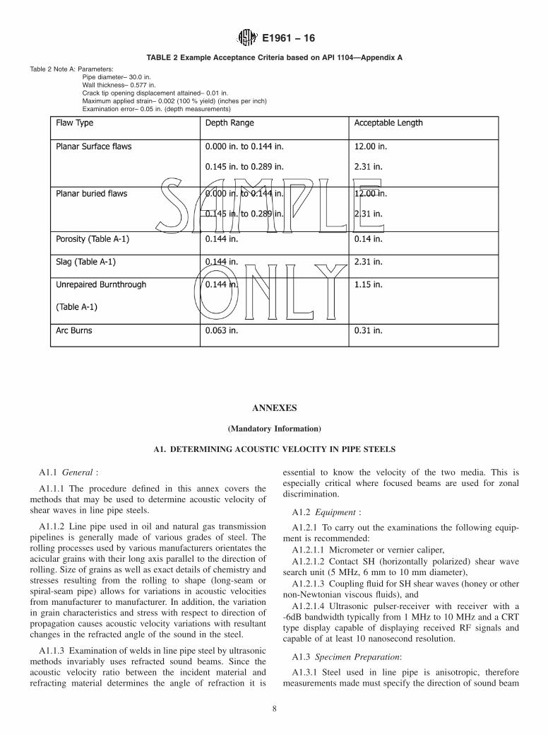
12.1 Standards of acceptability are to be established by thecontracting agency. These may be based on workmanship orEngineering Critical Assessment (ECA) calculations. Ex-amples of ECA determined acceptance criteria are shown inTables 1 and 2 (see Note 1).
NOTE 1—Values in Table 1 and Table 2 are provided in only metric(Table 1) or inch pound (Table 2), as they are actual industry examples.Each is derived from different calculations and only the units of calcula-tion are used in the table.
13. Keywords
13.1 contact focused search units; girth welds; mechanizedultrasonics
E1961 − 16
6

TABLE 1 Mechanized Girth Weld Acceptance CriteriaA,B,C
Table 1 Note A: Based on Appendix K of CSA-Z662.Table 1 Note B: This table is an example only. It is used here to illustrate how zonal discrimination can be applied to acceptance criteria. Acceptable lengths are basedon calculations derived from destructive testing for a specific material.
A External undercut, low cap, cap porosity and excessive external weld reinforcement may be assessed by visual examination.B Flaw interaction should be considered in defining the effective flaw length. See API 1104 Appendix A for examples of flaw interaction.C All welding procedures assessed in accordance with this criteria should be qualified according to the appropriate governing standard, for example CSA Z662, AppendixK or API 1104.
E1961 − 16
7
ANNEXES
(Mandatory Information)
A1. DETERMINING ACOUSTIC VELOCITY IN PIPE STEELS
A1.1 General :
A1.1.1 The procedure defined in this annex covers themethods that may be used to determine acoustic velocity ofshear waves in line pipe steels.
A1.1.2 Line pipe used in oil and natural gas transmissionpipelines is generally made of various grades of steel. Therolling processes used by various manufacturers orientates theacicular grains with their long axis parallel to the direction ofrolling. Size of grains as well as exact details of chemistry andstresses resulting from the rolling to shape (long-seam orspiral-seam pipe) allows for variations in acoustic velocitiesfrom manufacturer to manufacturer. In addition, the variationin grain characteristics and stress with respect to direction ofpropagation causes acoustic velocity variations with resultantchanges in the refracted angle of the sound in the steel.
A1.1.3 Examination of welds in line pipe steel by ultrasonicmethods invariably uses refracted sound beams. Since theacoustic velocity ratio between the incident material andrefracting material determines the angle of refraction it is
essential to know the velocity of the two media. This isespecially critical where focused beams are used for zonaldiscrimination.
A1.2 Equipment :
A1.2.1 To carry out the examinations the following equip-ment is recommended:
A1.2.1.1 Micrometer or vernier caliper,A1.2.1.2 Contact SH (horizontally polarized) shear wave
search unit (5 MHz, 6 mm to 10 mm diameter),A1.2.1.3 Coupling fluid for SH shear waves (honey or other
non-Newtonian viscous fluids), andA1.2.1.4 Ultrasonic pulser-receiver with receiver with a
-6dB bandwidth typically from 1 MHz to 10 MHz and a CRTtype display capable of displaying received RF signals andcapable of at least 10 nanosecond resolution.
A1.3 Specimen Preparation:
A1.3.1 Steel used in line pipe is anisotropic, thereforemeasurements made must specify the direction of sound beam
TABLE 2 Example Acceptance Criteria based on API 1104—Appendix A
Table 2 Note A: Parameters:Pipe diameter– 30.0 in.Wall thickness– 0.577 in.Crack tip opening displacement attained– 0.01 in.Maximum applied strain– 0.002 (100 % yield) (inches per inch)Examination error– 0.05 in. (depth measurements)
E1961 − 16
8
propagation. A minimum of three readings shall be made foreach plane in which examination will be done.
A1.3.1.1 A specimen is cut from a section of pipe to beexamined and the corresponding results are specific for aparticular pipe diameter, wall thickness and manufacturer.Specimen dimensions should be a minimum of 50 by 50 mm (2by 2 in.); however, larger sections may be preferred forhandling and machining.
A1.3.2 A minimum of two parallel surfaces are machinedfor the plane to be evaluated; one pair of surfaces is made in theradial direction (perpendicular to the outer surface) and theother pair made 20° from the perpendicular to the outersurface. Additional pairs of parallel surfaces may be machinedat other angles in the plane to be evaluated if more data pointsare desired.
A1.3.3 The machined surfaces should be smooth to a 20-µmfinish or better. Minimum width of the specimen surface to bemeasured should be 20 mm and the minimum thicknessbetween the parallel surfaces to be measured should be 10 mm.Vertical extent of the test surface will be limited by the pipewall thickness.
A1.4 Procedure :
A1.4.1 Using the micrometer or vernier caliper measure thethickness of the steel specimen between the machined parallelfaces.
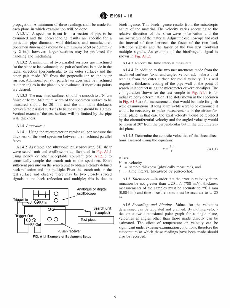
A1.4.2 Assemble the ultrasonic pulser/receiver, SH shearwave search unit and oscilloscope as illustrated in Fig. A1.1using honey or other acceptable couplant (see A1.2.1) toacoustically couple the search unit to the specimen. Exertsufficient pressure on the search unit to obtain a clearly definedback reflection and one multiple. Pivot the search unit on thetest surface and observe there may be two closely spacedsignals at the back reflection and multiple; this is due to
birefringence. This birefringence results from the anisotropicnature of the material. The velocity varies according to therelative direction of the shear-wave polarization and themicrostructure of the material. Adjust the oscilloscope and readthe interval of time between the faster of the two backreflection signals and the faster of the two first frontwallmultiple signals. An example of the birefringent signal isshown in Fig. A1.2.
A1.4.3 Record the time interval measured.
A1.4.4 In addition to the two measurements made from themachined surfaces (axial and angled velocities), make a thirdreading from the outer surface for radial velocity. This willrequire a thickness reading of the pipe wall at the point ofsearch unit contact using the micrometer or vernier caliper. Theconfiguration shown for the test sample in Fig. A1.1 is forradial velocity determination. The slots shown in the specimenin Fig. A1.3 are for measurements that would be made for girthweld examinations. If long seam welds were to be examined itwould be necessary to make measurements in the circumfer-ential plane, in that case the axial velocity would be replacedby the circumferential velocity and the angled velocity wouldbe taken at 20° from the perpendicular but in the circumferen-tial plane.
A1.4.5 Determine the acoustic velocities of the three direc-tions assessed using the equation:
V 52dt
(A1.1)
where:V = velocity,d = sample thickness (physically measured), andt = time interval (measured by pulse-echo).
A1.5 Tolerances —In order that the error in velocity deter-mination be not greater than 620 m/s (780 in./s), thicknessmeasurements of the samples must be accurate to 60.1 mm(0.004 in.) and time measurements must be accurate to 6 25ns.
A1.6 Recording and Plotting—Values for the velocitiesdetermined can be tabulated and graphed. By plotting veloci-ties on a two-dimensional polar graph for a single plane,velocities at angles other than those made directly can beestimated. The effect of temperature on velocity can besignificant under extreme examination conditions, therefore thetemperature at which these readings have been made shouldalso be recorded.FIG. A1.1 Example of Equipment Setup
E1961 − 16
9

A2. TYPICAL SEARCH UNIT CONFIGURATION
A2.1 Fig. A2.1 illustrates a typical configuration for searchunit array placement on a girth weld. Motion is facilitatedusing mechanized carrier on a welding band which keeps thesearch unit exit points at fixed distances from the weldcenterline.
A2.2 Fig. A2.2 illustrates an example of beam configura-tions used to examine a weld in a single pass. The weld bevelillustrated is used in an Automatic Gas Metal Arc Welding
(GMAW) process. The six zones identified would be typical ofa pipe wall thickness of 12.6 mm (0.496 in.). Search unitplacement is symmetric about the weld centerline. Only searchunits used on one side of the weld are illustrated.
FIG. A1.2 Example of Time Interval Measured in Birefringent Ma-terial
FIG. A1.3 Steel Specimen
E1961 − 16
10
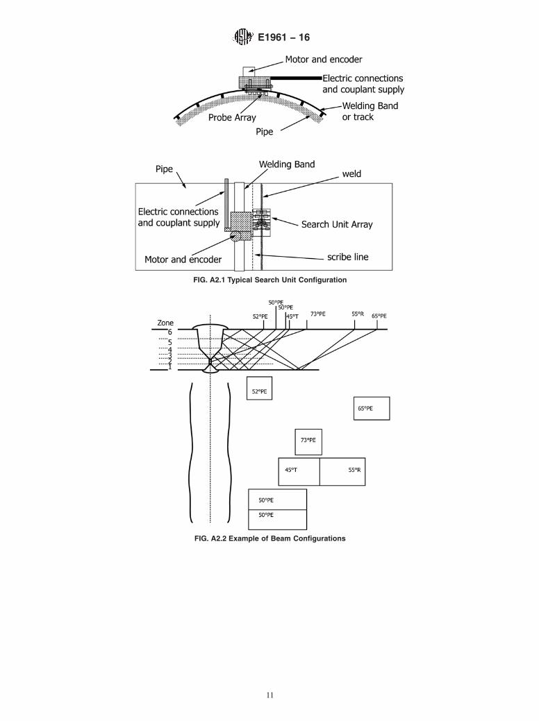
FIG. A2.1 Typical Search Unit Configuration
FIG. A2.2 Example of Beam Configurations
E1961 − 16
11

A3. MINIMUM REQUIREMENTS FOR REFERENCE STANDARDS
A3.1 Instrument Standardization—A reference standardshall be constructed and used to standardize the system anddemonstrate proper positioning and performance of the scan-ning apparatus.
A3.2 Material :
A3.2.1 Material used shall be taken from pipe of the samemanufacturer, diameter, thickness, and seam type as that to beexamined.
A3.2.2 Acoustic velocity shall be determined using SHshear waves for specific angles cut from the same pipe materialto be used (see Annex A1).
A3.3 Dimensions —Overall dimensions of the referencestandard and its actual shape shall be determined by the size ofthe search unit array and block support structure. The standard(and its mounting) shall provide sufficient surface area topermit the entire search unit array to traverse the target area ofthe reference standard during dynamic standardization scan-ning. The standard and mounting should be equipped with apermanently mounted welding band to allow the array to becorrectly positioned and moved during dynamic standardiza-tion scanning.
A3.4 Identification —All standards shall be permanentlyidentified using hard stamps. Information recorded for eachreference standard shall include; manufacturer, diameter, wallthickness, acoustic velocity and serial number. The serialnumber shall be used to trace recorded information withregards to acoustic velocities, manufacturer and target infor-mation.
A3.5 Targets :
A3.5.1 Targets shall be arranged to allow zonal discrimina-tion based on both weld profile and number of fill passes. (SeeFig. A3.1).
A3.5.2 Primary reference targets for fusion areas should betypically 2 to 3 mm (0.08 to 0.12 in.) diameter flat-bottomholes (FBH).
A3.5.3 Square slots 1 mm (0.04 in.) deep and 2 mm (0.080in.) wide should be machined typically 1 to 2 cm (0.4 to 0.8 in.)long on the design fusion line to indicate locations whereundercut or surface breaking non-fusion would occur on thepipe outer surface. Slots may also be used for the root fusionzone. Root slots should be typically 1 to 2 cm (0.4 to 0.8 in.)long and their depth and angular configuration should beidentical to the root bevel used in the weld process beingexamined.
A3.5.4 A centerline through hole, 2 mm (0.08 in.) diameter,should be drilled to verify detectability of centerline flaws andto ensure gate length is sufficient to cover 1 mm (0.04 in.) pastthe weld centerline.
A3.6 Lateral positioning of the targets shall be such as toallow for independent signals. The beam of each search unitshall pass across the target without any part of the beamencountering adjacent targets during the time the primarytarget is in the beam. (See Fig. A3.2).
E1961 − 16
12

NOTE 1—Fig. A3.1 uses a weld bevel configuration typical of the automatic gas metal arc welding process to illustrate the minimum number of targetsfor a more complex weld bevel geometry.
FIG. A3.1 Illustrations of Targets
NOTE 1—Fig. A3.2 illustrates placement of holes and slots relative to the weld centerline for a six-zoned weld similar to the configuration used in Fig.A3.1.
FIG. A3.2 Illustrations of Target Layout on Reference Standard Pipe Section
E1961 − 16
13

A3.7 The contractor may add other targets to the aboveminimum required in A3.5 provided they do not interfere withthe required targets.
A3.8 Tolerances —Tolerances of targets should be as fol-lows:
Hole diameters ±0.2 mm (0.008 in.)Slot lengths ±1.0 mm (0.040 in.)Slot depths ±0.2 mm (0.008 in.)All pertinent angles ±1°Center position of all targets ±0.2 mm (0.008 in.)
SUMMARY OF CHANGES
Committee E07 has identified the location of selected changes to this standard since the last issue (E1961 - 11)that may impact the use of this standard. (June 1, 2016)
(1) Added ISO 9712 to 2.7 and subsection 5.2.1.(2) Corrected subsection 8.2.2, to use “specular” in place of“perpendicular.”(3) Addressed re-examination criteria for missing data lines insubsection 10.7.3.
(4) Renumbered notes in Table 1 from “Note 1” and Note 2” to“Table 1 Note A” and “Table 1 Note B.”(5) Renumbered note in Table 2 from “Note 1” to “Table 2Note A.”
ASTM International takes no position respecting the validity of any patent rights asserted in connection with any item mentionedin this standard. Users of this standard are expressly advised that determination of the validity of any such patent rights, and the riskof infringement of such rights, are entirely their own responsibility.
This standard is subject to revision at any time by the responsible technical committee and must be reviewed every five years andif not revised, either reapproved or withdrawn. Your comments are invited either for revision of this standard or for additional standardsand should be addressed to ASTM International Headquarters. Your comments will receive careful consideration at a meeting of theresponsible technical committee, which you may attend. If you feel that your comments have not received a fair hearing you shouldmake your views known to the ASTM Committee on Standards, at the address shown below.
This standard is copyrighted by ASTM International, 100 Barr Harbor Drive, PO Box C700, West Conshohocken, PA 19428-2959,United States. Individual reprints (single or multiple copies) of this standard may be obtained by contacting ASTM at the aboveaddress or at 610-832-9585 (phone), 610-832-9555 (fax), or [email protected] (e-mail); or through the ASTM website(www.astm.org). Permission rights to photocopy the standard may also be secured from the Copyright Clearance Center, 222Rosewood Drive, Danvers, MA 01923, Tel: (978) 646-2600; http://www.copyright.com/
E1961 − 16
14