standard ecma-312 · 2018-11-14 · standard ecma-312 international 3rd edition - june 2003...
TRANSCRIPT
Standard ECMA-312
International
3rd Edition - June 2003
S t anda rd i z ing In fo rma t ion and Commun ica t i on Sys t ems
Private Integrated Services Network (PISN) – Profile Standard for the Use of PSS1 (QSIG) in Air Traffic Services Networks
Phone/Fax: +41 22 849.60.00/01 - http://www.ecma-international.org - mailto: he [email protected]

.
Standard ECMA-312
International
3rd Edition - June 2003
S t anda rd i z ing In fo rma t ion and Commun ica t i on Sys t ems
Private Integrated Services Network (PISN) – Profile Standard for the Use of PSS1 (QSIG) in Air Traffic Services Networks
Phone/Fax: +41 22 849.60.00/01 - http://www.ecma-international.org - mailto: he [email protected] IW ECMA-312.doc 02-07-03 11,33

.

Brief History
This Standard is one of a series of ECMA Standards defining services and signalling protocols applicable to Private Integrated Services Networks (PISNs). The series uses ISDN concepts as developed by ITU-T and conforms to the framework of International Standards for Open Systems Interconnection as defined by ISO/IEC.
This Standard specifies the functional profile for interconnecting Private Integrated services Network eXchanges (PINX) in Air Traffic Services (ATS) PISNs to permit interoperability between equipment from different vendors.
This Standard is based upon the practical experience of ECMA member companies and the results of their active and continuous participation in the work of ISO/IEC JTC1, ITU-T, ETSI and other international and national standardization bodies. It represents a pragmatic and widely based consensus.
Compared to the 2nd Edition of Standard ECMA-312 (published by ECMA in June 2001), this 3rd Edition incorporates changes proposed in the light of practical experience gained from implementations based upon the 2nd Edition.
Adopted as 3rd Edition of Standard ECMA-312 by the General Assembly of June 2003.

.

- i -
Table of contents
1 Scope 1
2 Conformance 1
3 References (normative) 1
4 Definit ions 2 4 .1 External def ini t ions 2
5 List of acronyms 3
6 Specif icat ion framework 4 6 .1 General 4 6 .2 Terminal Equipment (TE) 5 6 .3 Pr ivate Terminat ion System (PTS) 5 6 .4 Switching (SW) 5 6 .5 Mapping (MP) 5 6 .6 Cal l Control (CC) 5
7 Physical interface and protocol stack at the C reference point 6
8 Switching (SW) funct ions 6 8 .1 Speech compress ion 6
9 Mapping (MP) funct ions 6 9 .1 Physical layer funct ions 6
9 .1 .1 Physical and electr ical in terface requirements 7 9 .1 .2 Rate adaptat ion and sub-mult ip lexing 7 9 .1 .3 Alarm Indicat ion Signal (AIS) 7 9 .1 .4 Synchronisat ion 7
9 .2 Data l ink layer funct ions 7 9 .2 .1 General procedures 7 9 .2 .2 System parameters 8
9 .3 Octet synchronisat ion procedure 8
10 Call Control (CC) funct ions - End PINX case 8 10.1 Basic cal l es tabl ishment and clear ing 8 10.2 Message segmentat ion and re-assembly 9 10.3 STATUS ENQUIRY procedure 9 10.4 Overlap sending / receiving procedures 9 10.5 Cal l request and t ransmiss ion of the SETUP message 9 10.6 Information channel se lect ion 9 10.7 Agreement of channel and cal l proceeding 10 10.8 Cal l conf irmation indicat ion 10
- i i -
10 .9 Cal l connected 10 10.10 Use of the PROGRESS message 10 10.11 Fai lure of cal l es tabl ishment 10 10.12 Cal l c lear ing 10 10.13 Cal l col l is ions 11 10.14 Alternat ive route ing 11 10.15 Timer values 11 10.16 Support of information e lements 12
10.16.1 General 12 10.16.2 Bearer capabi l i ty 12 10.16.3 Cal l s ta te 13 10.16.4 Cal led par ty number 13 10.16.5 Cal l ing par ty number 13 10.16.6 Cause 14 10.16.7 Channel ident i f icat ion 14
10.17 Restar t procedure for layer management 14 10.18 Gener ic Funct ional Protocol 14
10.18.1 Applicable par ts of the Gener ic Funct ional Protocol 14 10.18.2 Support of information e lements 15 10.18.3 Integer encoding of operat ion values 16
10.19 Specif ic supplementary services 16 10.20 Prior i ty in terrupt ion and in trusion 16
10.20.1 Signal l ing procedures 16 10.20.2 Cal l control procedures 18 10.20.3 Invocat ion of pr ior i ty funct ions a t Originat ing PINX 18 10.20.4 Execut ion of SS-CPI 20
10.21 Transi t counter 20
11 Call Control (CC) funct ions - Transit PINX case 20 11.1 General 20
Annex A - Requirements List (RL) 23
Annex B - Prof i le specif ic ICS proforma 39
Annex C - Faci l i ty information element contents encoding 45

1 Scope This Profile Standard specifies the combination of base standards, together with the selection of appropriate options and parameter values, necessary to specify how QSIG / PSS1 can be used to provide digital signalling capabilities between Private Integrated services Networks eXchange (PINX) in an Air Traffic Services (ATS) PISN.
This Standard defines:
- physical and electrical characteristics (physical layer) of the interfaces to the transmission systems to be employed;
- data link layer procedures to ensure error-free communications links;
- network layer procedures for call establishment and clearing; and
- supplementary services to meet specific ATS requirements.
This Standard states requirements upon implementations in order to achieve interoperability between equipment in ATS PISNs.
NOTE 1 Implementation of this Standard does not preclude a manufacturer from offering other means of interconnection.
This Standard does not specify requirements related to interworking between QSIG and other signalling systems used in ATS PISNs.
2 Conformance A system conforms to this Standard if it correctly performs all the mandatory capabilities defined in the Requirement List (RL) (annex A) and the profile specific Implementation Conformance Statement (ICS) (annex B). Note that more capabilities may be mandatory than in the base standards.
3 References (normative) The following standards contain provisions which, through reference in this text, constitute provisions of this Standard. All standards are subject to revision, and parties to agreements based on this Standard are encouraged to investigate the possibility of applying the most recent editions of the standards indicated below.
In the case of references to ECMA Standards that are aligned with ISO/IEC International Standards, the number of the appropriate ISO/IEC International Standard is given in brackets after the ECMA reference.
ECMA-133 Private Integrated Services Network (PISN) - Reference Configuration for PISN Exchanges (PINX) (International Standard ISO/IEC 11579-1)
ECMA-143 Private Integrated Services Network (PISN) - Circuit Mode Bearer Services - Inter-Exchange Signalling Procedures and Protocol (International Standard ISO/IEC 11572)
ECMA-165 Private Integrated Services Network (PISN) - Generic Functional Protocol for the Support of Supplementary Services - Inter-Exchange Signalling Procedures and Protocol (International Standard ISO/IEC 11582)
ECMA-203 Private Integrated Services Network (PISN) - Inter-Exchange Signalling Protocol - Call Intrusion Supplementary Service (International Standard ISO/IEC 14846)
ECMA-225 Private Integrated Services Network (PISN) - Inter-Exchange Signalling Protocol - Transit Counter Additional Network Feature (International Standard ISO/IEC 15056)
ECMA-253 Private Integrated Services Network (PISN) - Mapping Functions for the Employment of 64 kbit/s Circuit Mode Connections with 16 kbit/s Sub-Multiplexing (International Standard ISO/IEC 17310)
- 2 -
ECMA-264 Private Integrated Services Network (PISN) - Inter-Exchange Signalling Protocol - Call Priority Interruption and Call Priority Interruption Protection Supplementary Services (International Standard ISO/IEC 15992)
ETS 300 290 Business TeleCommunications (BTC); 64 kbit/s digital unrestricted leased line with octet integrity (D64U); Terminal equipment interface (1994)
ETS 300 290 Amd. 1 Business TeleCommunications (BTC); 64 kbit/s digital unrestricted leased line with octet integrity (D64U); Terminal equipment interface (1995)
ETS 300 402-1 Integrated Services Digital Network (ISDN); Digital Subscriber Signalling System No. one (DSS1) protocol; Data link layer; Part 1: General aspects [ITU-T Recommendation Q.920 (1993), modified] (1995)
ETS 300 402-2 Integrated Services Digital Network (ISDN); Digital Subscriber Signalling System No. one (DSS1) protocol; Data link layer; Part 2: General protocol specification [ITU-T Recommendation Q.921 (1993), modified] (1995)
ETS 300 402-4 Integrated Services Digital Network (ISDN); Digital Subscriber Signalling System No. one (DSS1) protocol; Data link layer; Part 4: Protocol Implementation Conformance Statement (PICS) proforma specification for the general protocol (1999)
ISO/IEC 9646-7 Information technology - Open Systems Interconnection - Conformance testing methodology and framework - Part 7: Implementation Conformance Statements (1994)
ITU-T Rec. G.728 Coding of speech at 16 kbit/s using low-delay code excited linear prediction (1992)
ITU-T Rec. I.112 Vocabulary of terms for ISDNs services (1993)
ITU-T Rec. I.130 Method for the characterization of telecommunication services supported by an ISDN and network capabilities of an ISDN (Blue Book) (1988)
ITU-T Rec. I.140 Attribute technique for the characterization of telecommunication services supported by an ISDN and network capabilities of an ISDN (1993)
ITU-T Rec. I.210 Principles of telecommunication services supported by an ISDN and the means to describe them (1993)
ITU-T Rec. T.50 International Reference alphabet (IRA) (Formerly International Alphabet No. 5 or IA5) - Information technology - 7-bit coded character set for information interchange (1992)
4 Definitions For the purposes of this Standard, the following definitions apply.
4.1 External definit ions This Standard uses the following terms defined in other documents:
– C reference point (ECMA-133)
– Destination PINX (ECMA-165)
– End PINX (ECMA-165)
– Gateway PINX (ECMA-143)
– Incoming Call (ECMA-143)
– Inter-PINX Connection (ECMA-253)
– Inter-PINX Link (ECMA-253)
– Mapping functional group (ECMA-133)
– Originating PINX (ECMA-143)
- 3 -
– Outgoing Call (ECMA-143)
– Preceding PINX (ECMA-165)
– Private Integrated Services Network (PISN) (ECMA-133)
– Private Integrated Services Network Exchange (PINX) (ECMA-133)
– Q reference point (ECMA-133)
– Side, Incoming Side and Outgoing Side (ECMA-143)
– Source PINX (ECMA-165)
– S reference point (ECMA-133)
– Subsequent PINX (ECMA-165)
– Terminating PINX (ECMA-143)
– Transit PINX (ECMA-143)
5 List of acronyms ACSE Association Control Service Element
AIS Alarm Indication Signal
ANF Additional Network Feature
APDU Application Protocol Data Unit
ASN.1 Abstract Syntax Notation One
ATS Air Traffic Services
CC Call Control
CICL Call Intrusion Capability Level
CIPL Call Intrusion Protection Level
CPICL Call Priority Interruption Capability Level
CPIPL Call Priority Interruption Protection Level
DSE Dialogue Service Element
ETS European Telecommunication Standard
GFT Generic Functional Transport
HLC High Layer Compatibility
i Irrelevant
ICS Implementation Conformance Statement
IPCC Inter-PINX Connection Control
LD-CELP Low Delay Code Excited Linear Prediction
LLC Low Layer Compatibility
m Mandatory
MP MaPping
n/a Not Applicable
NFE Network Facilities Extension
o Optional
o.i Optional, qualified
- 4 -
PINX Private Integrated Services Network Exchange
PISN Private Integrated Services Network
PSS1 Private Signalling System no. 1
PTS Private Termination System
QSIG Q reference point SIGnalling system
RL Requirements List
ROSE Remote Operations Service Element
SCM Signalling Carriage Mechanism
SS-CI Call Intrusion Supplementary Service
SS-CPI Call Priority Interruption Supplementary Service
SS-CPIP Call Priority Interruption Protection Supplementary Service
SW SWitching
TE Terminal Equipment
TEI Terminal Endpoint Identifier
x eXcluded
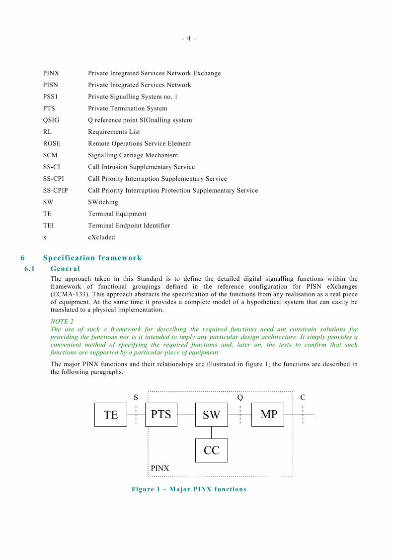
6 Specification framework 6.1 General
The approach taken in this Standard is to define the detailed digital signalling functions within the framework of functional groupings defined in the reference configuration for PISN eXchanges (ECMA-133). This approach abstracts the specification of the functions from any realisation as a real piece of equipment. At the same time it provides a complete model of a hypothetical system that can easily be translated to a physical implementation.
NOTE 2 The use of such a framework for describing the required functions need not constrain solutions for providing the functions nor is it intended to imply any particular design architecture. It simply provides a convenient method of specifying the required functions and, later on, the tests to confirm that such functions are supported by a particular piece of equipment.
The major PINX functions and their relationships are illustrated in figure 1; the functions are described in the following paragraphs.
MPSWTE
PINX
PTSCQ
CC
S
Figure 1 – Major PINX funct ions
- 5 -
The model in figure 1, and the functionality defined by it, represents a single instance of a service invocation (i.e., a call). A PINX claiming conformance with this Standard shall be capable of providing multiple simultaneous instances of the defined functions.
6.2 Terminal Equipment (TE) The TE function provides the necessary means for a human user, by actions at the Human Machine Interface, to initiate outgoing calls to or respond to incoming calls from another TE function. The TE function may be simple (e.g., a simple telephone handset) or complex (e.g., an ATS Controller Working Position).
The detailed requirements of this function are outside the scope of this Standard.
6.3 Private Termination System (PTS) The PTS function provides transmission and signalling capabilities between the TE function and the SW function. The PTS function, if necessary, adapts the physical, electrical and procedural conditions of the interface used to attach a TE to the PINX, to the internal conditions of the PINX.
The detailed requirements of this function are outside the scope of this Standard.
6.4 Switching (SW) The SW function provides the capability to switch user information and signalling information.
User information is switched between the PTS function and the MP function. Selection of the switching path depends upon the parameters of the service request.
Signalling information is switched between:
- the PTS function and the CC function; and
- between the CC function and the MP function.
NOTE 3 The switching function may also switch both user and signalling information between the described functions and other functions outside the scope of this Standard.
The detailed requirements of this function are specified in clause 8.
6.5 Mapping (MP) The MP function provides adaptation of the internal conditions of the PINX to the physical, electrical, and procedural conditions of the interface used to attach the PINX to an external transmission facility (e.g., a leased circuit) for inter-PINX communications.
The MP function also provides the multiplexing functions required to separate or merge the user information and signalling information from the PINX to the transmission facility employed.
The detailed requirements of this function are specified in clause 9.
6.6 Call Control (CC) The CC function provides the functions necessary to control calls between TE functions attached to the ATS PISN. It incorporates all the components of the PSS1 (QSIG) protocol model (i.e., Protocol Control, Call Control, GFT-Control, the Coordination function, and applicable SS-Control entities) described in ECMA-143 and ECMA-165.
NOTE 4 The CC function also provides the functions necessary to control calls between TE functions attached to the ATS PISN and other subscribers (e.g., connected to the public telecommunications network). It can also provide signalling interworking functions when necessary. However, these aspects are outside the scope of this Standard.
NOTE 5 In this Standard, requirements applicable to the CC function are specified separately for each of the following cases:
- Outgoing and Incoming sides of a ATS QSIG Call (End PINX case); and,
- 6 -
- Interworking between an Incoming side and an Outgoing side (Transit PINX case).
The detailed requirements of this function are specified in clauses 10 and 11.
7 Physical interface and protocol stack at the C reference point Figure 1 above also shows, using vertical dashed lines, the "reference points" at which physical interfaces may occur. This Standard defines the required behaviour at a physical interface at the C reference point. Figure 2 below shows the protocol stack applicable at the C reference point.
PISN User Plane (User information)
PISN Control Plane (Signalling)
Data Voice
PISN Call Control and Supplementary Services
Network layer
PSS1 (QSIG) Protocol Control
ECMA-143, ECMA-165
Data link layer
Symmetric LAP-D ETS 300 402-2 (Annex ZA)
Physical LD-CELP ITU-T Rec. G.728 layer 64 kbit/s sub-multiplexed (4 x 16 kbit/s) ETS 300 290, ECMA-253
Physical Transmission Medium
Figure 2 – Protocol s tack
8 Switching (SW) functions 8.1 Speech compression
For 16 kbit/s speech calls in which the PINX acts as the "End PINX", the SW function shall provide a speech compression and decompression capability (CELP codec) according to the requirements of ITU-T Recommendation G.728. Outgoing speech information from the PINX shall be compressed using the encoding algorithm specified in ITU-T Recommendation G.728. Speech information incoming to the PINX shall be decompressed using the decoding algorithm specified in ITU-T Recommendation G.728.
NOTE 6 The CELP codec described in ITU-T Recommendation G.728 contains selectable options to permit operation with modem or other non-speech signals. Such operation is not anticipated in the ATS context.
The bit-stealing method, as specified in ITU-T Recommendation G.728 / § 3.11, shall be used for synchronising the LD-CELP bitstream. The stolen bits shall be an alternating sequence of zeros and ones (i.e., either 010101… or 101010…).
For calls in which the PINX acts as a "Transit PINX", speech information shall not be decompressed and re-compressed.
9 Mapping (MP) functions 9.1 Physical layer functions
NOTE 7 The physical interface and sub-multiplexing techniques specified in 9.1.1 below have been selected as appropriate for ATS PISNs. The inclusion of other physical interfaces (e.g., at 2 048 kbit/s) in a future edition of this Standard is not precluded.
One consequence of this is that the number of channels and their attributes (e.g., information transfer rate, user information layer 1 protocol) at the Q reference point may be different from that presently specified.

- 7 -
Such a change implies changes to the requirements to be met by the Mapping function and the Call Control function.
A further consequence is that, when the inter-PINX connection is provided by means of a leased circuit, establishment of the connection is achieved through an administrative procedure with the leased circuit provider. Functions for the control of the connection (i.e., the IPCC functional group, as specified in ECMA-133) are needed only when on-demand connections (e.g., through the public ISDN) are used as the inter-PINX connection.
Suppliers should be aware of these possibilities and may wish to design their solutions accordingly.
9.1.1 Physical and electrical interface requirements The MP function shall meet the requirements for physical and electrical characteristics specified in ETS 300 290 and its amendment.
9.1 .2 Rate adaptat ion and sub-mult iplexing The MP function shall meet the requirements specified in ECMA-253 for sub-multiplexing a 64 kbit/s circuit-mode inter-PINX connection into 4 x 16 kbit/s channels.
The MP function shall provide a rate adaptation capability. Incoming speech information shall be adapted to the internal channel rate. Outgoing speech information shall be adapted from the internal channel rate to the rate required by the external transmission facility, as specified in ECMA-253.
9.1 .3 Alarm Indicat ion Signal (AIS) If the MP function receives multiple octets (i.e., >3 octets) containing an all one's bit pattern from the external transmission facility it shall assume this to be an Alarm Indication Signal (AIS). The MP function shall assume the transmission facility and / or the peer PINX is out of service and take appropriate management action.
The MP function shall be capable of sending AIS towards the external transmission facility when it detects loss of bit violations in the received bit stream. On resumption of normal bit violations the MP function shall stop sending AIS.
NOTE 8 There may be other, implementation dependant, circumstances when the MP function is required to send AIS. These are outside the scope of this Standard.
9.1 .4 Synchronisat ion Synchronisation functions of the MP function shall be compatible with the synchronisation strategy of the PINX. That is to say, the MP function shall be capable of both (but not simultaneously):
- Extracting the timing received at the receive side of the physical interface and delivering it as an external clock source for the entire system, and synchronising the MP function's own output timing to this source; and
- Synchronising the MP function's own output timing to another clock source not derived from the physical interface associated with this MP function.
Selection of the option shall be by system configuration and runtime determination.
9.2 Data l ink layer functions 9.2 .1 General procedures
The MP function shall support data link layer procedures as specified in annex ZA of ETS 300 402-2, with modifications as specified in the following subclauses.
NOTE 9 In these subclauses, references of the form: (§ x.x.x) refer to subclauses in ETS 300 402-2. References of the form (see x.x.x) refer to the present document.
A PINX shall provide a management means of configuring the MP function for each inter-PINX link to be either the "master" side or the "slave" side (§ ZA.2.3.2). The designation of any particular MP function as either a "master" or a "slave" shall not be influenced by nor shall it influence the configuration of any other MP function in the same PINX.
- 8 -
There is no need for a PINX to support the unacknowledged mode of operation (§ ZA.4.2).
When no layer 3 information is to be transmitted, the transmitting data link layer entity shall continuously send flag sequences in the D-channel (§ ZA.1.2).
NOTE 10 This requirement permits the receiving data link entity to perform octet synchronisation functions (9.3 below) without impact on the transmitting entity.
The transmitting data link layer entity shall always send an opening flag and a closing flag for each layer 2 frame transmitted (i.e., the closing flag of one frame shall not serve as the opening flag of the next frame) (§ ZA.1.2).
NOTE 11 This requirement permits the receiving data link entity to perform octet synchronisation functions without impact on the transmitting entity.
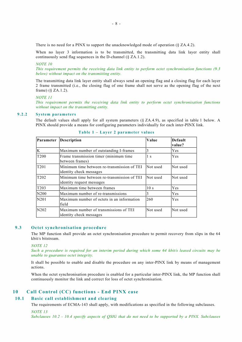
9.2.2 System parameters The default values shall apply for all system parameters (§ ZA.4.9), as specified in table 1 below. A PINX should provide a means for configuring parameters individually for each inter-PINX link.
Table 1 – Layer 2 parameter values
Parameter Description Value Default value?
K Maximum number of outstanding I-frames 3 Yes T200 Frame transmission timer (minimum time
between frames) 1 s Yes
T201 Minimum time between re-transmission of TEI identity check messages
Not used Not used
T202 Minimum time between re-transmission of TEI identity request messages
Not used Not used
T203 Maximum time between frames 10 s Yes N200 Maximum number of re-transmissions 3 Yes N201 Maximum number of octets in an information
field 260 Yes
N202 Maximum number of transmissions of TEI identity check messages
Not used Not used
9.3 Octet synchronisation procedure The MP function shall provide an octet synchronisation procedure to permit recovery from slips in the 64 kbit/s bitstream.
NOTE 12 Such a procedure is required for an interim period during which some 64 kbit/s leased circuits may be unable to guarantee octet integrity.
It shall be possible to enable and disable the procedure on any inter-PINX link by means of management actions.
When the octet synchronisation procedure is enabled for a particular inter-PINX link, the MP function shall continuously monitor the link and correct for loss of octet synchronisation.
10 Call Control (CC) functions - End PINX case 10.1 Basic call establishment and clearing
The requirements of ECMA-143 shall apply, with modifications as specified in the following subclauses.
NOTE 13 Subclauses 10.2 - 10.4 specify aspects of QSIG that do not need to be supported by a PINX. Subclauses
- 9 -
10.5 and onwards specify requirements additional to those in ECMA-143. The headings used in subclauses 10.5 onwards correspond to heading titles in ECMA-143.
NOTE 14 In these subclauses, references of the form: (§ x.x.x) refer to subclauses in ECMA-143. References of the form (see x.x.x) refer to the present document.
10.2 Message segmentation and re-assembly Annex ZA (Message segmentation and re-assembly) of ECMA-143 shall not apply.
10.3 STATUS ENQUIRY procedure A PINX shall not support initiation of the STATUS ENQUIRY procedure (§ 9.3.1).
NOTE 15 This means that the options in various error cases (e.g., where a message is received with a message type or message sequence error (§ 9.2.4), or during data link reset (§ 9.2.8) or failure (§ 9.2.9)) of ECMA-143 that permit an entity to send a STATUS ENQUIRY message shall not be supported.
10.4 Overlap sending / receiving procedures A PINX (Incoming Side) need not support the Overlap Receiving state (§ 7.1.14). Similarly a PINX acting as a Transit PINX need not support the TCC_Await Additional Digits state (§ 10.4.3).
A PINX (Outgoing Side) shall not initiate calls using states and procedures for overlap sending.
10.5 Call request and transmission of the SETUP message Call request (§ 10.1.1) and transmission of the SETUP message (§ 10.5.1) shall be modified according to the requirements in the following paragraphs.
If, due to congestion, no B-channel is available for the requested call, and if previously requested (e.g., by the TE function due to Class of Service or Priority Key depression), Call Control shall immediately perform the "execution" function of the Call priority interruption supplementary service (see 10.20.4). If no request for call priority interruption was made, Call Control shall initiate call establishment on an alternative route (see 10.14).
If, due to a reason other than congestion, no B-channel is available, Call Control shall initiate call establishment on an alternative route (see 10.14).
The Bearer capability information element sent in the SETUP message shall be encoded (see 10.16.2) to indicate "Speech 16 kbit/s" or "Unrestricted digital information 16 kbit/s", as appropriate.
The Called party number information sent in the SETUP message shall be complete. The transmitted SETUP message shall always contain the Sending complete information element.
Within the Calling party number and Called party number information elements, the Type of number field shall always be encoded as "Unknown". The Numbering plan identification field shall always be encoded as "Private numbering plan".
The Channel identification information element shall be encoded using "channel numbering". The "channel map" coding option shall not be used.
The transmitted SETUP message shall always contain the Transit counter information element, as specified in ECMA-225, with the transit count field set to the value zero.
If requested (e.g., by the TE function due to Class of Service or Priority Key depression), the transmitted SETUP message shall contain a Facility information element containing the callInterruptionRequest invoke APDU of the Call priority interruption supplementary service (see 10.20).
On the first expiry of timer T303 the Outgoing Side shall send a RELEASE COMPLETE message to the Incoming Side containing cause number 102 "recovery on timer expiry". The PINX shall initiate call establishment on an alternative route (see 10.14).
10.6 Information channel selection A PINX shall provide a management means of configuring the CC function for each inter-PINX link to be either the "A" side or the "B" side. The designation of any particular CC function as either an "A" side or a
- 10 -
"B" side shall not be influenced by nor shall it influence the configuration of any other CC function in the same PINX.
When initiating a call a PINX shall assign channels starting with the lowest available channel number if it is the "A" side and the highest available channel number if it is the "B" side (§ 10.3).
Call Control (Outgoing Side) shall indicate the selected channel as "preferred" in the Channel identification information element (§ 10.1.2).
If no channel is available when the SETUP message is received by the Incoming Side (assuming that the Outgoing Side sent the SETUP message when a channel was available), the Incoming Side shall check to determine whether call collision has occurred. If a call collision has occurred the PINX shall proceed as described in 10.13. If no call collision has occurred, the Incoming Side shall send a RELEASE COMPLETE message containing cause number 34 "no circuit/channel available".
10.7 Agreement of channel and call proceeding On receipt of the first message (normally CALL PROCEEDING) in response to the transmitted SETUP message indicating the channel to be used, the Outgoing Side shall through-connect the channel in both directions of transmission. If the Incoming Side indicated an alternative channel, the Outgoing Side shall use this channel (§ 10.1.2); the Outgoing side shall not clear the call in this case.
On receipt of a CALL PROCEEDING message an Outgoing Side shall always start timer T310. The value of timer T310 is specified in 10.15.
On expiry of timer T310 (occurs first in the Originating PINX) the Outgoing Side shall initiate call clearing. The clearing cause sent to the Incoming Side shall be cause number 102 "recovery on timer expiry". The PINX shall initiate call establishment on an alternative route (see 10.14).
10.8 Call confirmation indication The Outgoing Side shall start Timer T301 on receipt of an ALERTING message. The value of timer T301 is specified in 10.15.
On expiry of timer T301 the Outgoing Side shall initiate call clearing. The clearing cause sent to the Incoming Side shall be cause number 19 "no answer from user (user alerted)".
10.9 Call connected A PINX (Incoming Side) shall not support the Connect Request state (§ 7.1.8), timer T313, and the associated procedures (§ 10.1.6).
On receiving an indication that the call has been answered and requires through-connection of the B-channel in both directions of transmission, the Incoming Side shall send a CONNECT message to the Outgoing Side and enter the Active state (§ 10.1.6).
On receipt of the CONNECT message the Outgoing Side shall stop timers T310 and/or T301 and enter the Active state (§ 10.1.6). A CONNECT ACKNOWLEDGE message shall not be sent.
10.10 Use of the PROGRESS message NOTE 16 During call establishment, the call may leave the ATS QSIG environment due to interworking with another signalling system. The PINX at the point of interworking (the Outgoing Gateway PINX) will send progress indications to indicate this.
On receipt of a PROGRESS message containing a Progress indicator information element containing progress description number 1 "call is not end-to-end ISDN, further call progress information may be available in-band" timer T310 shall be stopped. (§ 10.1.7)
10.11 Failure of call establishment No additional requirements (§ 10.1.8).
10.12 Call clearing In the exception case where call clearing is initiated towards the called user before a channel has been agreed (§ 10.2.2, 3rd item) the RELEASE message shall be used. A DISCONNECT message shall not be used in this case.
- 11 -
10.13 Call coll is ions NOTE 17 Call collision occurs when two calls originating from PINX at opposite ends of an inter-PINX link attempt to use the same B-channel. ECMA-143 specifies how this situation shall be dealt with.
The procedures specified in the first case ("A" side preferred, "B" side preferred) of § 10.3 of ECMA-143 shall apply, except when the priorities of the colliding calls are different.
NOTE 18 Call Priority Interruption Capability Level (CPICL) information (see 10.20.3) can be used to determine the priority of each call.
If no free channel exists the call originating from the "B" side shall be cleared. The "B" side shall attempt to establish the call using an alternative route (10.14).
In the case where the relative priorities of the colliding calls are different, the call with the higher priority shall be awarded the channel. An alternative channel (if free channels exist) shall be indicated in the first response to the side originating the lower priority call (§ 10.3). If no free channel exists the lower priority call shall be cleared. The side originating the lower priority call shall attempt to establish the call using an alternative route (10.14).
10.14 Alternative routeing For each possible destination address, a PINX shall maintain an ordered list of up to 5 alternative routes. Each list shall be configurable by management means.
The routeing algorithm to be used under normal conditions, for routeing calls with no priority, shall be based on attempting to establish the call on each route in a list sequentially, with the most direct route being the first attempted. A PINX shall await the outcome of the call attempt on a particular route before proceeding to try the next available route.
NOTE 19 Priority calls take a different approach based on pre-empting busy circuits (see 10.20 and 10.5).
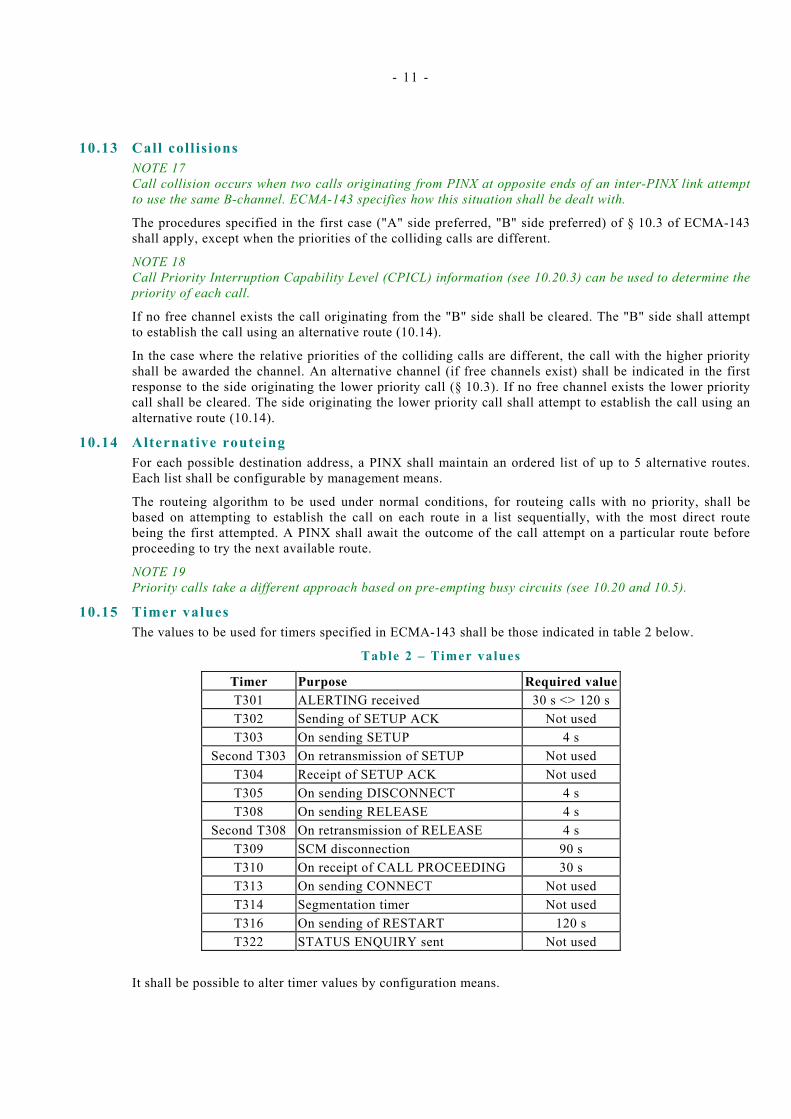
10.15 Timer values The values to be used for timers specified in ECMA-143 shall be those indicated in table 2 below.
Table 2 – Timer values
Timer Purpose Required value T301 ALERTING received 30 s <> 120 s T302 Sending of SETUP ACK Not used T303 On sending SETUP 4 s
Second T303 On retransmission of SETUP Not used T304 Receipt of SETUP ACK Not used T305 On sending DISCONNECT 4 s T308 On sending RELEASE 4 s
Second T308 On retransmission of RELEASE 4 s T309 SCM disconnection 90 s T310 On receipt of CALL PROCEEDING 30 s T313 On sending CONNECT Not used T314 Segmentation timer Not used T316 On sending of RESTART 120 s T322 STATUS ENQUIRY sent Not used
It shall be possible to alter timer values by configuration means.
- 12 -
10.16 Support of information elements 10.16.1 General
NOTE 20 The requirements for the support and encoding of information elements (§ 14) specified in this and subsequent subclauses are additional to any implied requirements arising from the procedures specified for Basic Call establishment and clearing in preceding subclauses.
A Call Control function need not generate the following information elements:
- Called party subaddress;
- Calling party subaddress;
- Connected number;
- Connected party subaddress;
- High layer compatibility (HLC); and,
- Low layer compatibility (LLC).
An End PINX receiving a message containing one or more of the non-mandatory information elements listed above shall ignore those information elements that it does not recognise (§ 10.6.1).
NOTE 21 A Transit PINX must transparently pass-on these information elements (§ 10.4.11.2).
Other information elements shall be supported as described in ECMA-143 (§ 14), with modifications as specified in the following subclauses.
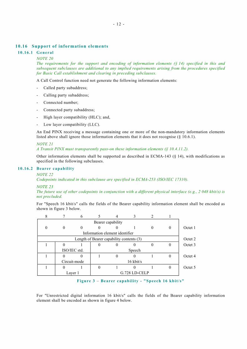
10.16.2 Bearer capabi l i ty NOTE 22 Codepoints indicated in this subclause are specified in ECMA-253 (ISO/IEC 17310).
NOTE 23 The future use of other codepoints in conjunction with a different physical interface (e.g., 2 048 kbit/s) is not precluded.
For "Speech 16 kbit/s" calls the fields of the Bearer capability information element shall be encoded as shown in figure 3 below.
8 7 6 5 4 3 2 1 Bearer capability
0 0 0 0 0 1 0 0 Octet 1 Information element identifier
Length of Bearer capability contents (3) Octet 2 1 0 1 0 0 0 0 0 Octet 3 ISO/IEC std. Speech
1 0 0 1 0 0 1 0 Octet 4 Circuit-mode 16 kbit/s
1 0 1 0 1 0 1 0 Octet 5 Layer 1 G.728 LD-CELP
Figure 3 – Bearer capabi l i ty - "Speech 16 kbit /s"
For "Unrestricted digital information 16 kbit/s" calls the fields of the Bearer capability information element shall be encoded as shown in figure 4 below.
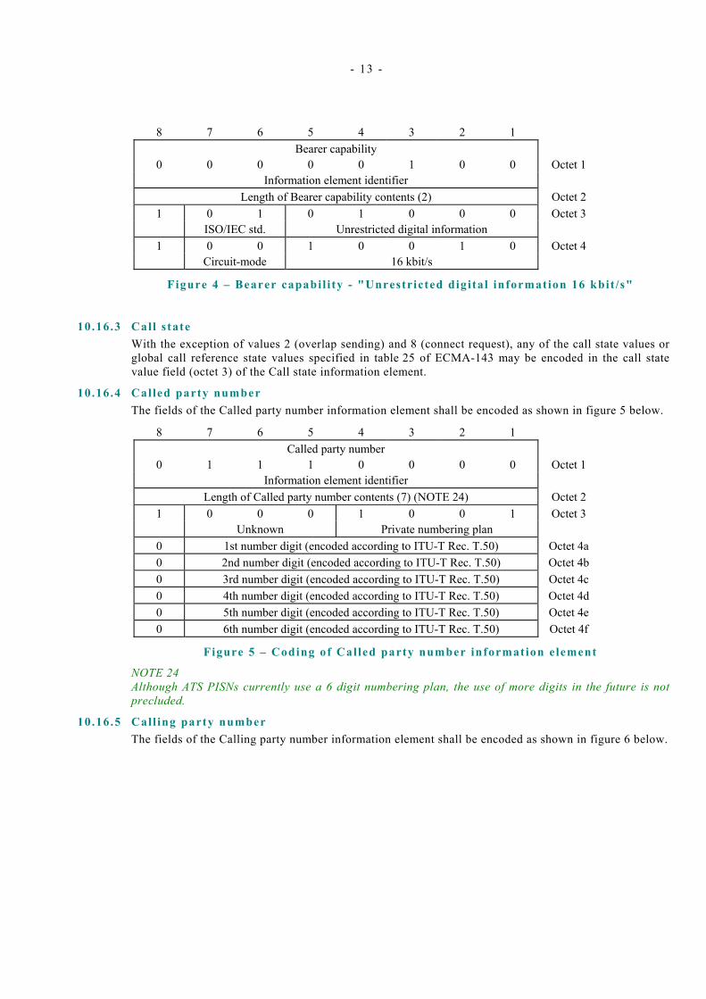
- 13 -
8 7 6 5 4 3 2 1 Bearer capability
0 0 0 0 0 1 0 0 Octet 1 Information element identifier
Length of Bearer capability contents (2) Octet 2 1 0 1 0 1 0 0 0 Octet 3 ISO/IEC std. Unrestricted digital information
1 0 0 1 0 0 1 0 Octet 4 Circuit-mode 16 kbit/s
Figure 4 – Bearer capabi l i ty - "Unrestricted digital information 16 kbit /s"
10.16.3 Call s tate With the exception of values 2 (overlap sending) and 8 (connect request), any of the call state values or global call reference state values specified in table 25 of ECMA-143 may be encoded in the call state value field (octet 3) of the Call state information element.
10.16.4 Called party number The fields of the Called party number information element shall be encoded as shown in figure 5 below.
8 7 6 5 4 3 2 1 Called party number
0 1 1 1 0 0 0 0 Octet 1 Information element identifier
Length of Called party number contents (7) (NOTE 24) Octet 2 1 0 0 0 1 0 0 1 Octet 3 Unknown Private numbering plan
0 1st number digit (encoded according to ITU-T Rec. T.50) Octet 4a 0 2nd number digit (encoded according to ITU-T Rec. T.50) Octet 4b 0 3rd number digit (encoded according to ITU-T Rec. T.50) Octet 4c 0 4th number digit (encoded according to ITU-T Rec. T.50) Octet 4d 0 5th number digit (encoded according to ITU-T Rec. T.50) Octet 4e 0 6th number digit (encoded according to ITU-T Rec. T.50) Octet 4f
Figure 5 – Coding of Cal led party number information element
NOTE 24 Although ATS PISNs currently use a 6 digit numbering plan, the use of more digits in the future is not precluded.
10.16.5 Cal l ing party number The fields of the Calling party number information element shall be encoded as shown in figure 6 below.

- 14 -
8 7 6 5 4 3 2 1 Calling party number
0 1 1 0 1 1 0 0 Octet 1 Information element identifier
Length of Calling party number contents (7) (NOTE 25) Octet 2 1 0 0 0 1 0 0 1 Octet 3 Unknown Private numbering plan NOTE 26
0 1st number digit (encoded according to ITU-T Rec. T.50) Octet 4a 0 2nd number digit (encoded according to ITU-T Rec. T.50) Octet 4b 0 3rd number digit (encoded according to ITU-T Rec. T.50) Octet 4c 0 4th number digit (encoded according to ITU-T Rec. T.50) Octet 4d 0 5th number digit (encoded according to ITU-T Rec. T.50) Octet 4e 0 6th number digit (encoded according to ITU-T Rec. T.50) Octet 4f
Figure 6 – Coding of Cal l ing party number information element
NOTE 25 Although ATS PISNs currently use a 6 digit numbering plan, the use of more digits in the future is not precluded.
NOTE 26 A Call Control function need not generate octet 3a (presentation / screening indicator), but should be prepared to receive a Calling party information element containing octet 3a, without treating it as an error.
10.16.6 Cause A Call Control function need not generate octet 5 (Diagnostics), but should be prepared to receive a Cause information element containing octet 5, without treating it as an error.
The Location field (octet 3, bits 4-1) shall be encoded as "0 0 0 1" (Private network serving the local user), unless interworking with another network is involved.
10.16.7 Channel identif icat ion The Channel number (octet 3.3) shall be encoded as the binary number (range 1-3) assigned to the channel, as specified in 8.2.1 of ECMA-253.
NOTE 27 The range of channel numbers permitted is appropriate to support one inter-PINX connection according to the requirements of ECMA-253. The future specification of other inter-PINX connections with different physical interfaces, and hence different ranges of channel numbers, is not precluded.
10.17 Restart procedure for layer management The restart procedure (§ 11.1) shall not be used to restart single channels. Hence, only the value "1 1 1" (All channels) shall be used in the Restart indicator information element.
In the case that timer T308 expires for the second time, the appropriate channel in the link shall be placed in an "out-of-service" condition. Call Control shall inform the appropriate management and maintenance entity. Under automatic or manual control the management and maintenance entity may invoke the restart procedure for the complete link.
NOTE 28 Other circumstances in which the restart procedure can be used are system dependant, and outside the scope of this Standard.
10.18 Generic Functional Protocol 10.18.1 Applicable parts of the Generic Functional Protocol
To permit support of QSIG supplementary services, a PINX shall support a subset of the Generic Functional Protocol specified in ECMA-165.

- 15 -
A PINX shall support the Remote Operations Service Element (ROSE) and the connection oriented APDU transport mechanism. Requirements for other service elements (i.e., ACSE and DSE) and for other transport mechanisms (i.e., connection-less APDU transport) need not be supported. Table 3 below identifies the applicable subclauses of ECMA-165 specifying the necessary requirements.
Table 3 – Applicable and non-applicable c lauses of ECMA-165
Applicable subclauses of ECMA-165 Non-applicable subclauses of ECMA-165 1, 2, 3, 4, 5, 6.1(a), 6.2, 6.3, 6.4, 6.7.1, 6.7.3, 6.8.1, 6.8.3, 6.1(b), 6.1(c), 6.5, 6.6, 6.7.2, 6.8.2, 6.9, 7.1, 7.3 (NOTE 29), 7.4, 7.2, 8.1.1, 8.1.2, 8.2, 8.3, 8.4, 9 (NOTE 30) 10, 11
NOTE 29 Support of the call independent signalling mechanism (7.3 in ECMA-165) is not specifically required for ATS PISNs at present. However, future editions of this Standard may introduce additional supplementary services for which it is needed. Suppliers are advised to take account of this in their implementations.
NOTE 30 Suppliers may choose whether or not to support manufacturer specific operations.
The procedures for call independent signalling connections (7.3 in ECMA-165) contain several options. In these cases the appropriate modifications specified in this Standard as applicable for Basic Call shall also apply to call independent signalling connections.
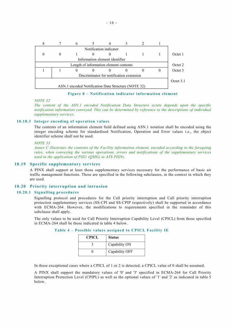
10.18.2 Support of information e lements The fields of the Facility information element shall, in accordance with 11.3.3 of ECMA-165, be encoded as shown in figure 7 below.
8 7 6 5 4 3 2 1 Facility
0 0 0 1 1 1 0 0 Octet 1 Information element identifier
Length of information element contents Octet 2 1 0 0 1 1 1 1 1 Octet 3 Networking extensions Octet 3.1
Network Facility Extension (NFE) (NOTE 31) Octets 4
Service APDU(s) (NOTE 31) etc.
Figure 7 – Faci l i ty information element
NOTE 31 The content of the Network Facility Extension (NFE) and the Service APDU octets depends upon the specific supplementary service information conveyed. This can be determined by reference to the descriptions of individual supplementary services.
The fields of the Notification indicator information element shall, in accordance with 11.3.4 of ECMA-165, be encoded as shown in figure 8 below.
- 16 -
8 7 6 5 4 3 2 1 Notification indicator
0 0 1 0 0 1 1 1 Octet 1 Information element identifier
Length of information element contents Octet 2 1 1 0 0 0 0 0 0 Octet 3 Discriminator for notification extension Octet 3.1
ASN.1 encoded Notification Data Structure (NOTE 32)
Figure 8 – Noti f icat ion indicator information element
NOTE 32 The content of the ASN.1 encoded Notification Data Structure octets depends upon the specific notification information conveyed. This can be determined by reference to the descriptions of individual supplementary services.
10.18.3 Integer encoding of operat ion values The contents of an information element field defined using ASN.1 notation shall be encoded using the integer encoding scheme for standardised Notification, Operation and Error values i.e., the object identifier scheme shall not be used.
NOTE 33 Annex C illustrates the contents of the Facility information element, encoded according to the foregoing rules, when conveying the various operations, errors and notifications of the supplementary services used in the application of PSS1 (QSIG) to ATS PISNs.
10.19 Specific supplementary services A PINX shall support at least those supplementary services necessary for the performance of basic air traffic management functions. These are specified in the following subclauses, in the context in which they are used.
10.20 Priority interruption and intrusion 10.20.1 Signal l ing procedures
Signalling protocol and procedures for the Call priority interruption and Call priority interruption protection supplementary services (SS-CPI and SS-CPIP respectively) shall be supported in accordance with ECMA-264. However, the modifications to requirements specified in the remainder of this subclause shall apply.
The only values to be used for Call Priority Interruption Capability Level (CPICL) from those specified in ECMA-264 shall be those indicated in table 4 below.
Table 4 – Possible values ass igned to CPICL Faci l i ty IE
CPICL Status
3 Capability ON
0 Capability OFF
In those exceptional cases where a CPICL of 1 or 2 is detected, a CPICL value of 0 shall be assumed.
A PINX shall support the mandatory values of '0' and '3' specified in ECMA-264 for Call Priority Interruption Protection Level (CPIPL) as well as the optional values of '1' and '2' as indicated in table 5 below.

- 17 -
Table 5 – Possible values ass igned to CPIPL Faci l i ty IE
CPIPL Protection
3 Total protection
2 High protection
1 Low protection
0 No protection
Signalling protocol and procedures for the Call intrusion supplementary service (SS-CI) shall be supported in accordance with ECMA-203. A PINX need only support the following options:
- Invocation without path retention; and,
- Conference type connection.
The only values to be used for Call Intrusion Capability Level (CICL) from those specified in ECMA-203 shall be those indicated in table 6 below.
Table 6 – Possible values ass igned to CICL Faci l i ty IE
CICL Status
3 Capability ON
0 Capability OFF
In those exceptional cases where a CICL of 1 or 2 is detected, a CICL value of 0 shall be assumed.
The only values to be used for Call Intrusion Protection Level (CIPL) from those specified in ECMA-203 shall be those indicated in table 7 below.
Table 7 – Possible CIPL values
CIPL Status
3 Protected
0 Not protected
NOTE 34 There is no FACILITY message defined containing CIPL. This value is assigned to individual terminals (or to all terminals) attached to a PINX.
In those exceptional cases where a CIPL of 1 or 2 is returned in a ciGetCIPL response, a CIPL value of 0 shall be assumed
The values to be used for the SS-CI timers specified in ECMA-203 shall be those indicated in table 8 below.

- 18 -
Table 8 – Values for SS-CI t imers
Timer Purpose Required value
T1 Absence of response to SS-CI invocation by Originating PINX 30 s T2 Absence of response to a request for isolation Not used T3 Absence of response to a request for forced release Not used T4 Absence of response to a request for wait on busy Not used T5 Absence of response to request for CIPL value by Terminating
PINX 10 s
T6 Length of impending intrusion warning 10 s PRT1 Path retention timer (see note to item B5 in subclause A.3.4.1.2 of
annex A) 60 s
10.20.2 Call control procedures Calls with a bearer capability of "Unrestricted digital information 16 kbit/s" shall not be capable of interrupting other calls. Neither shall such calls be interruptible by other calls. Thus, they shall have CPICL / CICL = 0 and CPIPL / CIPL = 3.
For calls with a bearer capability of "Speech 16 kbit/s", Call Control shall support procedures for interruption and intrusion as specified in the following subclauses.
NOTE 35 Each TE function is assigned (e.g., by class of service) a protection level; any call made from a particular TE function assumes that protection level. Regardless of the protection level assigned to the TE function, depression of a "Priority" key before a call request is made, causes a priority call to be made, with a total protection associated with it.
NOTE 36 Call interruption by a priority call in the case of circuit congestion occurs as a result of:
A "Priority" key depression:
- Prior to a call request being initiated;
- After receipt of a busy (congestion) signal due to the unavailability of circuits;
Call Intrusion occurs as a result of:
A "Priority" key depression:
- prior to a call request being initiated (in the case that the called user is busy);
- after receipt of a busy signal due to the called user being busy;
10.20.3 Invocat ion of priority funct ions at Originat ing PINX When a TE function with an assigned protection initiates a call request, Call Control shall invoke SS-CPI. Call Control shall encode the Call Priority Interruption Protection Level (CPIPL) as shown in table 9 below, and send the information with the SETUP message transmitted to the next PINX (see 10.5). No Call Priority Interruption Capability Level (CPICL) or Call Intrusion Capability Level (CICL) information shall be included in the SETUP message i.e., the call is established as a protected call only.

- 19 -
Table 9 – Encoding of protect ion levels
Interruption Protection
Source of invocation
CPIPL From "total interruption protection" TE function 3 From "high interruption protection" TE function 2 From "low interruption protection" TE function 1 From TE function with no assigned interruption protection (also, the value to be assumed for calls without protection information)
0
For priority calls, Call Control shall encode the CPICL, CPIPL, and CICL as shown in table 10 below. The coded CPICL, CPIPL, and CICL information shall be sent with the SETUP message transmitted to the next PINX (see 10.5).
Table 10 – Encoding of capabil i ty / protect ion levels (Priority cal l case)
Intrude Capability
Interruption Capability
Interruption Protection
Source of invocation
CICL CPICL CPIPL Priority call 3 3 3
NOTE 37 The capability and protection levels for the priority key case apply for both SS-CPI and SS-CI.
When a "Priority" key is depressed, and there is no call request in progress from the TE function in question, Call Control shall wait until the next call request is received from the TE function before invoking both SS-CPI and SS-CI.
When a "Priority" key is depressed, and there is a call request in progress in which the calling user is receiving a busy (congestion) indication, Call Control shall terminate the existing call request using normal call clearing procedures (§ 10.2). Call Control shall invoke both SS-CPI and SS-CI, and immediately re-initiate a priority call attempt towards the same destination. The CPICL, CPIPL, and CICL shall be encoded as shown in table 10 above and shall be sent with the SETUP message transmitted to the next PINX (see 10.5).
When a "Priority" key is depressed, and there is a call request in progress in which the calling user is receiving a busy indication due to the called user being busy, Call Control shall terminate the existing call request using normal call clearing procedures (§ 10.2). Call Control shall invoke both SS-CPI and SS-CI, and immediately re-initiate a priority call attempt towards the same destination. The CPICL, CPIPL, and CICL shall be encoded as shown in table 10 above, and shall be sent with the SETUP message transmitted to the next PINX (see 10.5).
When a "Priority" key is depressed, and there is a call offer in progress (i.e., the calling user is receiving ringback but the call is not answered by the called user), Call Control shall terminate the existing call request using normal call clearing procedures (§ 10.2). Call Control shall invoke both SS-CPI and SS-CI and immediately re-initiate a priority call attempt towards the same destination. The CPICL, CPIPL, and CICL shall be encoded as shown in table 10 above, and shall be sent with the SETUP message transmitted to the next PINX (see 10.5).
NOTE 38 The effect at the Terminating PINX, of invoking SS-CI in this case, depends on the nature of the called destination and the design of the Terminating PINX. For genuinely ringing "simple telephones" where no one answers there will be no effect. For complex terminal equipment with multiple line appearances (such as an ATS Controller Working Position), the effect of the request for call intrusion should be a rejection with the appropriate Error message (i.e. ciError=not busy), because it is not possible to intrude into a call if the user is not in a busy state. Whether or not the call is automatically connected to the handset/headset or is directed to a loudspeaker located at the terminal equipment is supplier dependent. The priority call should however always be presented at the terminal.
- 20 -
10.20.4 Execution of SS-CPI Execution of SS-CPI can occur at any PINX meeting congestion on the route to a subsequent PINX.
If all B-channels in the preferred route are occupied (e.g., as determined in 10.5), Call Control shall check the CPICL of the call to be established, to determine whether call priority interruption is permitted. Priority calls with a CPICL value of 3 can interrupt calls with CPIPL values less than 3.
If interruption is not permitted, Call Control shall attempt to establish the call using an alternative route (see 10.14).
If interruption is permitted, Call Control shall select, from the calls using channels on the preferred route, a call with a CPIPL lower than 3. If more than one call has a CPIPL lower than 3 then the call with the lowest CPIPL shall be selected. If several calls have the same lowest CPIPL, Call Control may select any one of these.
Having selected the call to be interrupted, Call Control shall inform the parties involved that the call is to be released. Call Control shall do this by sending a NOTIFY message containing notification value "interruptionIsImpending" to each party in the call. Call Control shall also start the "Interruption pending" timer.
NOTE 39 Usually, there will only be 2 parties involved in the call to be released. The action to be taken in the case where the call to be released involves more than 2 parties (i.e., a conference) is implementation dependant.
On expiry of the Interruption pending timer Call Control shall force release the call to be interrupted by sending a DISCONNECT message containing the notification value "interruptionForcedRelease" to each party involved in the call.
On receiving a notification of an impending interruption, a PINX shall inject an audible tone (Interrupt warning tone) into the voice path to the user. This tone shall be applied until the interruptionForcedRelease notification is received. On receipt of this notification the PINX shall continue to clear the call using normal call clearing procedures (§ 10.2.3).
When clearing of the interrupted call has been completed, Call Control shall continue establishment of the priority call using the newly available B-channel. Call Control shall encode the CPICL and the CPIPL as shown in table 10 above, and send the coded CPICL and CPIPL information with the SETUP message transmitted to the next PINX (see 10.5).
10.21 Transit counter Transit counter functionality, as specified in ECMA-225, shall be supported.
A PINX shall provide a management means of configuring the acceptable (network dependent) value that the transit count field shall be allowed to reach (§ 6.4.3.2 of ECMA-225).
11 Call Control (CC) functions - Transit PINX case 11.1 General
Where appropriate, the modifications to the requirements of ECMA-143 for End PINX expressed above shall also apply to a PINX acting as a transit node (§ 10.4). In addition, the modifications to requirements specified in this clause shall also apply.
A Transit PINX shall through-connect the B-channel in both directions of transmission on receipt of the first message in response to SETUP indicating the B-channel to be used (§ 10.4.5).
A Transit PINX shall not discard any Progress message received in the TCC_Call Active state (§ 10.4.9).
A Transit PINX, on receipt of a DISCONNECT, RELEASE, or RELEASE COMPLETE message from the Subsequent PINX prior to reaching the TCC_Call Alerting state shall not attempt "other (unspecified) procedures" (§ 10.4.10.1).
A Transit PINX need not support procedures for the application of in-band tones and announcements during the call clearing phase (§ 10.4.10.2).

- 21 -
NOTE 40 This means a Transit PINX need not support states 11, 12, and 13 (§ 8.1) and the procedures associated with them.

- 22 -

- 23 -
Annex A (normative)
Requirements List (RL)
A.1 General Use of this Standard imposes requirements on the implementation that go beyond those of the base standards referred to by this Standard. These result in modifications to the requirements expressed in the PICS proformas for the base standards. This annex specifies the modifications (the Requirements List - RL) that apply to the status of the items affected in each PICS proforma, with consequently modified requirements on the answers to be provided.
The status notation used in this annex is that defined in ISO/IEC 9646-7. In summary, the meaning of the notations is as follows:
i Irrelevant or out-of-scope - this capability is outside the scope of this profile and is not subject to conformance testing in this context.
m Mandatory - the capability is required to be supported.
n/a Not Applicable - in the given context, it is impossible to use the capability.
o Optional - the capability may be supported or not.
o.i qualified optional - for mutually exclusive or selectable options from a set. "i" is an integer that identifies an unique group of related optional items and the logic of their selection, defined below the table.
x eXcluded or prohibited - there is a requirement not to support this capability in this profile.
The Requirements List in this annex shall be used to restrict the permitted support answers in the corresponding PICS.
A.2 Relationship between RL and corresponding PICS proformas In the context of the profile specification contained in this Standard, PICS proformas of the base protocol standards contain tables in 3 categories. The 3 categories are:
- Those proforma tables where this profile does not restrict the permitted support answers;
- Those proforma tables where this profile restricts the permitted support answers;
- Those proforma tables that are not relevant to this profile.
The Requirements List consists of the tables falling into the second category, with an indication of the modified items in those tables.
A.3 Requirement List A.3.1 Tables for the physical layer
The profile described by this Standard specifies no additional requirements to those in ECMA-253, ETS 300 290 and ITU-T Recommendation G.728.
- 24 -
A.3.2 Tables for the data l ink layer (D-channel) Item number and references refer to annex B of ETS 300 402-4.
A.3.2 .1 Major capabil i t ies Item Question/Feature Reference Protocol Status Profile Status
MC 2 the unacknowledged information transfer service?
ZA.4.2 o i
MC 5.1.1
the self initiated establishment of multiple frame operation?
ZA.4.5.1, ZA.4.5.5, ZA.4.5.6
o m
MC 5.2.1
the self initiated termination of multiple frame operation?
ZA.4.5.2, ZA.4.5.5, ZA.4.5.6
o m
A.3.2.2 Frames received Item Question/Feature Reference Protocol Status Profile Status
FR 12 UI command? ZA.2.6.5, ZA.4.2
MC 2:m NOT MC2:o
i i
A.3.2 .3 Frames transmitted Item Question/Feature Reference Protocol Status Profile Status
FT 9 DISC comment? ZA.2.6.4, ZA.4.5.3
MC 5.2.1:m NOT MC 5.2.1:o
m n/a
FT 12 UI command? ZA.2.6.5, ZA.4.2
o i

- 25 -
A.3.3 Tables for the network layer A.3.3 .1 Basic Call (ECMA-143)
Item numbers and references refer to ECMA-143.
A.3.3 .1 .1 Bearers supported
Item Question/Feature Reference Protocol Status Profile Status
Z1 Support of the 64 kbps unrestricted bearer
14.5.5 o.1 x (NOTE)
Z2 Support of the 64 kbps bearer with speech transfer capability
14.5.5 o.1 x (NOTE)
Z3 Support of the 64 kbps bearer with 3.1 kHz audio transfer capability
14.5.5 o.1 x (NOTE)
Z4 Support of the Multi-rate Unrestricted Bearer
14.5.5 o.1 x (NOTE)
Z5 Support of A-law User Information layer 1 protocol
14.5.5 (Z2 OR Z3):o.3 i
Z6 Support of µ-law User Information layer 1 protocol
14.5.5 (Z2 OR Z3):o.3 i
Z7 Support of the unrestricted digital information with tones / announcements bearer
14.5.5 o x
NOTE Items Z1 - Z4 are a group of optional items (o.1) that is notionally extended by additional items pD2 and pD3 from the Profile specific ICS (see annex B). Since items pD2 and pD3 have mandatory status in this Profile it is semantically permissible to exclude items Z1- Z4.
A.3.3 .1 .2 Status and Status Enquiry protocol procedures
Item Question/Feature Reference Protocol Status Profile Status
A14 Sending of a STATUS ENQUIRY message
9.3.1 o x
A15 Receipt of a solicited STATUS message
9.3.2 c.1 i

- 26 -
A.3.3.1 .3 Circuit switched cal l control
Item Question/Feature Reference Protocol Status Profile Status
B7 Does the implementation include a Sending Complete information element in every generated SETUP message ?
10.1.1 c.3 m
B9 Overlap Receiving procedures 10.1.3 c.4 i
B10 Overlap Sending procedures 10.1.3 c.5 n/a
Sending of CONNECT ACKNOWLEDGE message
10.1.6 (NOTE) x
Support of the Connect Request state and timer T313
10.1.6 (NOTE) x
B17 Sending of call progress information during call establishment
10.1.7 c.6 m
NOTE Item B16 in the PICS proforma includes a note indicating that the use of CONNECT ACKNOWLEDGE and the associated state and timer is optional. There are no specific PICS proforma questions relating to this so they are included here.
A.3.3.1 .4 Procedures for layer management
Item Question/Feature Reference Protocol Status Profile Status
H1 Initiation of Restart procedures - All channels
11.1.1 o m
H2 Initiation of Restart procedures - Multiple channels
11.1.1 Z4:o x
H3 Initiation of Restart procedures - Single channels
11.1.1 o x
A.3.3.1 .5 Timers
Item Question/Feature Reference Protocol Status Profile Status
I1 Implementation of T301 12 c.7 m
I9 Implementation of T313 12 c.11 x

- 27 -
A.3.3.1 .6 Messages and information elements for general procedures
Item Question/Feature Reference Protocol Status Profile Status
J4 Sending of a Sending Complete information element in an INFORMATION message when overlap sending is complete
13.2.6 o n/a
J5 Sending of a Progress Indicator information element in an ALERTING message (except when relaying at a Transit PINX in accordance with C4)
13.2.1 o m
J6 Sending of a Progress Indicator information element in a CONNECT message (except when relaying at a Transit PINX in accordance with C4)
13.2.3 o m
J12 Sending of a Sending Complete information element in a SETUP message when enbloc sending
13.2.10 o m
J13 Sending of a Progress Indicator information element in a SETUP message (except when relaying at a Transit PINX in accordance with C4)
13.2.10 o m
J14 Sending of a Calling Party Number information element in a SETUP message (except when relaying at a Transit PINX in accordance with C4)
13.2.10 o m
J20 Sending of a Channel Identification information element in a RESTART ACKNOWLEDGE message
13.3.2 o n/a
J21 Support of channel map 14.5.12 o x
J23 Type of number supported for Private Numbering Plan:
14.5.7 o
Unknown x Level 2 regional number x Level 1 regional number x PISN specific number m Level 0 regional number x Abbreviated number x
- 28 -
A.3.3 .1 .7 Message segmentat ion / re-assembly procedures
Item Question/Feature Reference Protocol Status Profile Status
K3 Is length of signalling carriage mechanism information field < max. generated message size
ZA.3 o x
K4 Is length of signalling carriage mechanism information field < max. received message size
ZA.3 o x
K5 Procedures for messages segmentation
ZA.3.1 c.12 x
A.3.3 .1 .8 Party category funct ionality
Item Question/Feature Reference Protocol Status Profile Status
N1 Party category functionality ZC.2 o x
A.3.3 .2 Generic Functional Protocol Item numbers refer to annex A of ECMA-165.
A.3.3.2 .1 Cal l re lated protocol control and GFT-Control requirements
Item Question/Feature Reference Protocol Status Profile Status
A1 Can the implementation act as a Source PINX for APDUs?
7.1.1.1 o m
A12 Can the implementation generate notification information?
7.4 o m
A.3.3.2 .2 Connect ionless ADPU transport mechanism
Item Question/Feature Reference Protocol Status Profile Status
B1 Does the PINX support Connectionless APDU transport?
7.2 o x
- 29 -
A.3.3 .2 .3 Connect ion oriented APDU transport mechanism
Item Question/Feature Reference Protocol Status Profile Status
C1 Does the PINX support connection-oriented APDU transport?
7.3 o m
C2 Can the implementation act as a Source PINX for APDUs when supporting the Connection oriented APDU transport mechanism?
7.3 C1:o m
C4 Actions at an Originating PINX 7.3.3.1 C1:o m
C6 Actions at a Terminating PINX 7.3.3.3 C1:o m
A.3.3 .2 .4 Coordinat ion Function requirements
Item Question/Feature Reference Protocol Status Profile Status
D1 Inclusion of an Interpretation APDU at a Source PINX
8.1.1 o m
A.3.3.2 .5 ACSE and DSE requirements
Item Question/Feature Reference Protocol Status Profile Status
G1 Does implementation support the ACSE protocol?
8.3 o x
F1 Does implementation support the DSE protocol?
8.4 o x
A.3.3.2 .6 Implemented parameters A.3.3 .2 .6 .1 ALERTING message
Item Question/Feature Reference Protocol Status Profile Status
J1 Facility information element - Orig 10.1, 11.3.3 A1:o.3 m
J3 Notification indicator information element - Orig
10.1, 11.3.4 A12:o.4 m
A.3.3 .2 .6 .2 CONNECT message
Item Question/Feature Reference Protocol Status Profile Status
K1 Facility information element - Orig 10.3, 11.3.3 c.2 m
K3 Notification indicator information element - Orig
10.3, 11.3.4 A12:o.4 m
- 30 -
A.3.3 .2 .6 .3 SETUP message
Item Question/Feature Reference Protocol Status Profile Status
L1 Facility information element - Orig 10.4, 11.3.3 c.2 m
L3 Notification indicator information element - Orig
10.4, 11.3.4 A12:o.4 m
L5 Transit counter information element - Orig
7.3.1.1, 6.3 of ECMA-225
o m
A.3.3 .2 .6 .4 DISCONNECT message
Item Question/Feature Reference Protocol Status Profile Status
M1 Facility information element - Orig 10.5, 11.3.3 A1:o.3 m
M3 Notification indicator information element - Orig
10.5, 11.3.4 A12:o.4 m
A.3.3 .2 .6 .5 RELEASE message
Item Question/Feature Reference Protocol Status Profile Status
N1 Facility information element - Orig 10.6, 11.3.3 c.2 m
A.3.3 .2 .6 .6 RELEASE COMPLETE message
Item Question/Feature Reference Protocol Status Profile Status
O1 Facility information element - Orig 10.7, 11.3.3 c.2 m
A.3.3 .2 .6 .7 FACILITY message Item Question/Feature Reference Protocol Status Profile Status
P1 FACILITY message - Orig 10.8 c.3 m
P14 Notification indicator information element - Orig
10.8, 11.3.4 c.4 m
A.3.3 .2 .6 .8 NOTIFY message
Item Question/Feature Reference Protocol Status Profile Status
Q1 NOTIFY message - Orig 10.9 A12:o.4 m

- 31 -
A.3.3 .2 .6 .9 PROGRESS message
Item Question/Feature Reference Protocol Status Profile Status
R1 Facility information element - Orig 10.10, 11.3.3 A1:o.3 m
R3 Notification indicator information element - Orig
10.10, 11.3.4 A12:o.4 m
A.3.4 Tables for Supplementary Services and ANFs A.3.4 .1 Cal l intrusion
Item numbers refer to annex A of ECMA-203.
A.3.4 .1 .1 General
Item Question/Feature Reference Protocol Status Profile Status
A1 Support of SS-CI in Originating PINX of an intruding call
6.6.1 o.1 m
A2 Support of SS-CI in Terminating PINX of an intruding call
6.6.2 o.1 m
A3 Support of SS-CI in Unwanted User PINX
6.6.3 o o
A4 Behaviour as gateway to support SS-CI from user in PISN to user in public ISDN
6.7 o x
A5 Behaviour as gateway to support SS-CI from user in PISN to user in other network (i.e., R2)
6.8 o m
A6 Behaviour as gateway to support SS-CI from user in other network (i.e., R2) to user in PISN
6.8 o m
A7 Behaviour as gateway to support CIPL request from Terminating PINX to another network
6.8 o m
A8 Behaviour as gateway to support CIPL request from another network to an Unwanted User PINX
6.8 o m

- 32 -
A.3.4 .1 .2 Procedures
Item Question/Feature Reference Protocol Status Profile Status
B1 Support of relevant ECMA-143 and ECMA-165 procedures
6.2.1, 6.2.2, 6.2.3 m m
B2 SS-CI invocation without path retention in Originating PINX
6.6.1.1, 6.6.1.6 A1:o.2 m
B3 SS-CI invocation with path retention in Originating PINX
6.6.1.1, 6.6.1.6, A.2.1, A.5.1
A1:o.2 x
B4 SS-CI invocation without path retention in Terminating PINX
6.6.2.1, 6.6.2.6 A2:m m
B5 SS-CI invocation with path retention in Terminating PINX
6.6.2.1, 6.6.2.6, A.2.2, A.5.2
A2:m m (NOTE)
B6 Notification of intrusion impending in Terminating PINX
6.6.2 A2:o m
B7 Notification of intrusion to calling user in Terminating PINX
6.6.2 B6:o m
B8 Forced release request in Originating PINX
6.6.1.3 A1:o x
B9 Forced release request in Terminating PINX
6.6.2.3 A2:o x
B10 Isolate request in Originating PINX
6.6.1.2 A1:o x
B11 Isolate request in Terminating PINX
6.6.2.2 A2:o x
B12 Wait on busy request in Originating PINX
6.6.1.4 A1:o x
B13 Wait on busy request in Terminating PINX
6.6.2.4 A2:o x
B14 Reinvocation of SS-CI after wait on busy in Originating PINX
6.6.1.4 B12:m x
B15 Reinvocation of SS-CI after wait on busy in Terminating PINX
6.6.2.4 B13:m x
B16 SS-CI invocation in Unwanted User PINX
6.6.3 A3:m m
NOTE The use of the path retention mechanism is not envisaged in the ATS application. A PINX conforming to this specification need not, therefore, support the associated states and procedures. However, not supporting the states and procedures on the terminating side may be considered as a non-compliance in any formal exercise to assess conformity with ECMA-203. Additionally, support of the states and procedures on the terminating side improves the possibility of achieving interoperability in the case where a PINX receives a SETUP message containing a pathRetain invoke APDU.
- 33 -
A.3.4 .1 .3 Coding
Item Question/Feature Reference Protocol Status Profile Status
C1 Sending of callIntrusionRequest invoke APDU and receipt of callIntrusionRequest return result and error APDU in Originating PINX
6.3.1 A1:m m
C2 Sending of pathRetain invoke APDU and receipt of serviceAvailable invoke APDU in Originating PINX
6.3.1 B3:m n/a
C3 Receipt of callIntrusionRequest invoke APDU and sending of callIntrusionRequest return result and error APDU in Terminating PINX
6.3.1 A2:m m
C4 Receipt of pathRetain invoke APDU and sending of serviceAvailable invoke APDU in Terminating PINX
6.3.1 A2:m m (NOTE)
C5 Sending of callIntrusionGetCIPL invoke APDU and receipt of callIntrusionGetCIPL return result APDU in Terminating PINX
6.3.1 A2:m m
C6 Receipt of callIntrusionGetCIPL invoke APDU and sending of callIntrusionGetCIPL return result APDU in Unwanted User PINX
6.3.1 A3:m m
C7 Sending of callIntrusionForcedRelease invoke APDU and receipt of callIntrusionForcedRelease return result APDU in Originating PINX
6.3.1 B8:m n/a
C8 Receipt of callIntrusionForcedRelease invoke APDU and sending of callIntrusionForcedRelease return result APDU in Terminating PINX
6.3.1 B9:m n/a
C9 Sending of callIntrusionIsolate invoke APDU and receipt of callIntrusionIsolate return result APDU in Originating PINX
6.3.1 B10:m n/a
C10 Receipt of callIntrusionIsolate invoke APDU and sending of callIntrusionIsolate return result APDU in Terminating PINX
6.3.1 B11:m n/a
continued …

- 34 -
Item Question/Feature Reference Protocol Status Profile Status
C11 Sending of callIntrusionWOBRequest invoke APDU and receipt of callIntrusionWOBRequest return result APDU in Originating PINX
6.3.1 B12:m n/a
C12 Receipt of callIntrusionWOB invoke APDU and sending of callIntrusionWOBRequest return result APDU in Terminating PINX
6.3.1 B13:m n/a
C13 Receipt of callIntrusionCompleted invoke APDU in Originating PINX
6.3.1 A1:m m
C14 Sending of callIntrusionCompleted invoke APDU in Terminating PINX
6.3.1 A2:m m
NOTE See note attached to PICS item B5 in subclause A.3.4.1.2.
A.3.4.1 .4 Timers
Item Question/Feature Reference Protocol Status Profile Status
D1 Support of timer T1 6.10 A2:m m
D2 Support of timer T2 6.10 B10:m n/a
D3 Support of timer T3 6.10 B8:m n/a
D4 Support of timer T4 6.10 B12:m n/a
D5 Support of timer T5 6.10 A2:m m
D6 Support of timer T6 6.10 B6:m m
D7 Support of timer PRT1 A.8 A2:m m (NOTE)
NOTE See footnote attached to PICS item B5.
- 35 -
A.3.4 .2 Cal l priority interruption (protect ion) Item numbers refer to annex A of ECMA-264.
A.3.4 .2 .1 General
Item Question/Feature Reference Protocol Status Profile Status
A1 Support of SS-CPI o.1 m
A2 Support of SS-CPIP o.1 m
A3 Support of SS-CPI in Originating PINX
6.8.1 A1:o.2 m
A4 Support of SS-CPI in Transit PINX 6.8.2 A1:o.2 m
A6 Support of SS-CPIP in Originating PINX
6.9.1 A2:o.3 m
A7 Support of SS-CPIP in Transit PINX
6.9.2 A2:o.3 m
A8 Support of SS-CPIP in Terminating PINX
6.9.3 A2:o.3 m
A9 SS-CPI behaviour as Incoming Gateway when interworking with public ISDN
6.10 A1:o m
A10 SS-CPI behaviour as Incoming Gateway when interworking with non-ISDNs
6.12 A1:o m
A11 SS-CPI behaviour as Outgoing Gateway when interworking with non-ISDNs
6.12 A1:o m
A12 SS-CPIP behaviour as Incoming Gateway when interworking with public ISDN
6.11 A2:o m
A13 SS-CPIP behaviour as Outgoing Gateway when interworking with public ISDN
6.11 A2:o m
A14 SS-CPIP behaviour as Incoming Gateway when interworking with non-ISDNs
6.13 A2:o m
A15 SS-CPIP behaviour as Outgoing Gateway when interworking with non-ISDNs
6.13 A2:o m

- 36 -
A.3.4 .2 .2 Procedures
Item Question/Feature Reference Protocol Status Profile Status
B5 Notification of interruption impending in Interrupting PINX
6.8.3 A5:o m
B9 SS-CPIP procedures in Terminating PINX - backward direction
6.9.3 A8:o x

- 37 -
A.3.4 .3 Transit counter Item numbers refer to annex A of ECMA-225.
A.3.4 .3 .1 General
Item Question/Feature Reference Protocol Status Profile Status
A1 Behaviour as an Originating PINX for ANF-TC in association with basic circuit switched call control
6.2.1, 6.4.1 o.1 m
A2 Behaviour as an Originating PINX for ANF-TC in association with call independent signalling connections
6.2.1, 6.4.1 o.1 m
A3 Behaviour as a Terminating PINX for ANF-TC in association with basic circuit switched call control
6.2.2, 6.4.2 o.1 m
A4 Behaviour as a Terminating PINX for ANF-TC in association with call independent signalling connections
6.2.2, 6.4.2 o.1 m
A5 Behaviour as a Transit PINX for ANF-TC in association with basic circuit switched call control
6.2.3, 6.4.3 o.1 m
A6 Behaviour as a Transit PINX for ANF-TC in association with call independent signalling connections
6.2.3, 6.4.3 o.1 m
A7 Behaviour as an Incoming Gateway PINX for ANF-TC in association with basic circuit switched call control
6.4.4 o.1 m
A8 Behaviour as an Incoming Gateway PINX for ANF-TC in association with call independent signalling connections
6.4.4 o.1 m
A9 Behaviour as an Outgoing Gateway PINX for ANF-TC in association with basic circuit switched call control
6.4.5 o.1 m
A10 Behaviour as an Outgoing Gateway PINX for ANF-TC in association with call independent signalling connections
6.4.5 o.1 m

- 38 -
- 39 -
Annex B (normative)
Profile specific ICS proforma
B.1 General The layout and content of this annex is guided by ISO/IEC 9646-7.
The supplier of a profile implementation that is claimed to conform to this Standard shall complete the Profile specific Implementation Conformance Statement (ICS) proforma contained in this annex.
NOTE The supplier is also required to complete a copy of the PICS proformas provided in each of the protocol standards referred to by this Standard.
A completed Profile specific ICS proforma is the ICS for the implementation in question. The ICS is a statement of which capabilities and options of the profile have been implemented. The ICS can have a number of uses, including use:
- By the profile implementer, as a check list to reduce the risk of failure to conform to the standard through oversight;
- By the supplier and acquirer (or potential acquirer) of the implementation, as a detailed indication of the capabilities of the implementation, stated relative to the common basis for understanding provided by the standard ICS proforma;
- By the user (or potential user) of the implementation, as a basis for initially checking the possibility of interworking with another implementation (note that, while interworking cannot be guaranteed, failure to interwork can often be predicted from incompatible ICS);
- By a protocol tester, as the basis for selecting appropriate test suites against which to assess the claim for conformance of the implementation.
B.2 Instruction for completing the ICS proforma B.2.1 General structure of the ICS proforma
The ICS proforma is a fixed format questionnaire divided into subclauses each containing a group of individual items. Each item is identified by an item number, the name of the item (question to be answered), and the reference(s) to either the base standard, or a specific clause in a base standard, or specifying the item in the main body of this Standard (if no base standard is listed in the reference column).
The "Status" column indicates whether an item is applicable and if so whether support is mandatory or optional. The following terms are used:
m mandatory (the capability is required for conformance to the profile);
o optional (the capability is not required for conformance to the profile but if the capability is implemented it is required to conform to the profile specification);
o.<n> optional, but support of at least one of the group of options labelled by the same numeral <n> is required;
<item>:m simple-conditional requirement, the capability being mandatory if item number <item> is supported, otherwise not applicable;
<item>:o simple-conditional requirement, the capability being optional if item number <item> is supported, otherwise not applicable;
- 40 -
x prohibited;
c.<cond> conditional requirement, depending on support for the item listed in condition <cond>.
Answers to the questionnaire items are to be provided in the "Support" column, by simply marking an answer to indicate a restricted choice (Yes or No), or in the "Not Applicable" column (N/A).
B.2.2 Additional Information Items of Additional information allow a supplier to provide further information intended to assist the interpretation of the ICS. It is not intended or expected that a large quantity will be supplied, and an ICS can be considered complete without any such information. Examples might be an outline of the ways in which a (single) implementation can be set up to operate in a variety of environments and configurations.
References to items of Additional information may be entered next to any answer in the questionnaire, and may be included in items of Exception Information.
B.2.3 Exception Information It may occasionally happen that a supplier will wish to answer an item with mandatory or prohibited status (after any conditions have been applied) in a way that conflicts with the indicated requirements, No pre-printed answer will be found in the Support column for this. Instead, the supplier is required to write into the support column an x.<i> reference to an item of Exception Information, and to provide the appropriate rationale in the Exception item itself.
An implementation for which a Exception item is required in this way does not conform to this Standard. A possible reason for the situation described above is that a defect in the standard has been reported, a correction for which is expected to change the requirement not met by the implementation.
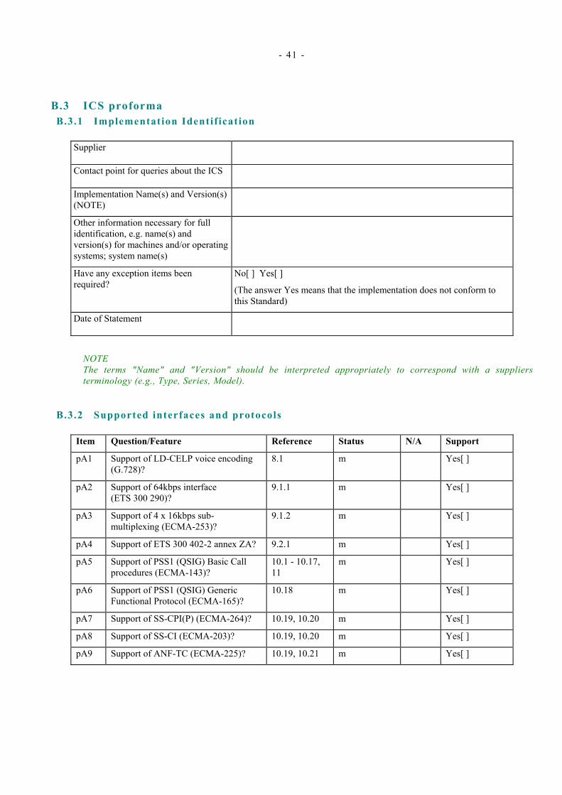
- 41 -
B.3 ICS proforma B.3.1 Implementation Identif ication
Supplier
Contact point for queries about the ICS
Implementation Name(s) and Version(s) (NOTE)
Other information necessary for full identification, e.g. name(s) and version(s) for machines and/or operating systems; system name(s)
Have any exception items been required?
No[ ] Yes[ ]
(The answer Yes means that the implementation does not conform to this Standard)
Date of Statement
NOTE The terms "Name" and "Version" should be interpreted appropriately to correspond with a suppliers terminology (e.g., Type, Series, Model).
B.3.2 Supported interfaces and protocols
Item Question/Feature Reference Status N/A Support
pA1 Support of LD-CELP voice encoding (G.728)?
8.1 m Yes[ ]
pA2 Support of 64kbps interface (ETS 300 290)?
9.1.1 m Yes[ ]
pA3 Support of 4 x 16kbps sub-multiplexing (ECMA-253)?
9.1.2 m Yes[ ]
pA4 Support of ETS 300 402-2 annex ZA? 9.2.1 m Yes[ ]
pA5 Support of PSS1 (QSIG) Basic Call procedures (ECMA-143)?
10.1 - 10.17, 11
m Yes[ ]
pA6 Support of PSS1 (QSIG) Generic Functional Protocol (ECMA-165)?
10.18 m Yes[ ]
pA7 Support of SS-CPI(P) (ECMA-264)? 10.19, 10.20 m Yes[ ]
pA8 Support of SS-CI (ECMA-203)? 10.19, 10.20 m Yes[ ]
pA9 Support of ANF-TC (ECMA-225)? 10.19, 10.21 m Yes[ ]

- 42 -
B.3.3 Physical layer
Item Question/Feature Reference Status N/A Support
pB1 Support of AIS? 9.1.3 m Yes[ ]
pB2 Support of synchronisation functions? 9.1.4 m Yes[ ]
pB3 G.728 bit stealing method for synchronising LD-CELP bitstream?
8.1 m Yes[ ]
pB4 No decompression at a Transit PINX? 8.1 m Yes[ ]
pB5 Octet synchronisation procedure? 9.3 m Yes[ ]
B.3.4 Data l ink layer
Item Question/Feature Reference Status N/A Support
pC1 Means of configuring PINX as "master" or "slave" side?
9.2.1 m Yes[ ]
pC2 Transmission of continuous flags between L2 frames?
9.2.1 m Yes[ ]
pC3 Every L2 frame has its own opening and closing flags?
9.2.1 m Yes[ ]
pC4 Means of configuring L2 parameters? 9.2.1 m Yes[ ]
pC5 Support of default values of L2 parameters?
9.2.1 m Yes[ ]

- 43 -
B.3.5 Network layer (Basic Call)
Item Question/Feature Reference Status N/A Support
pD1 Call request and transmission of the SETUP message?
10.5 m Yes[ ]
pD2 Support of the 16kbps unrestricted bearer?
10.5, 10.16.2, ECMA-253 annex C
m Yes[ ]
pD3 Support of the 16kbps bearer with speech capability?
10.5, 10.16.2, ECMA-253 annex C
m Yes[ ]
pD4 Support of G.728 LD-CELP User Information layer 1 protocol?
8.1, 10.16.2, ECMA-253 annex C
m Yes[ ]
pD5 Support of 6 digit PISN specific numbers?
10.5, 10.16.4, 10.16.5
m Yes[ ]
pD6 Information channel selection and binary channel numbers?
10.6, 10.16.7 m Yes[ ]
pD7 Agreement of channel and call proceeding?
10.7 m Yes[ ]
pD8 Call confirmation indication? 10.8 m Yes[ ]
pD9 Call connected? 10.9 m Yes[ ]
pD10 Use of the PROGRESS message? 10.10 m Yes[ ]
pD11 Call clearing and cause coding? 10.12, 10.16.6 m Yes[ ]
pD12 Call collisions? 10.13 m Yes[ ]
pD13 Alternative routeing? 10.14 m Yes[ ]
pD14 Timer values? 10.15 m Yes[ ]
pD15 Restart procedures? 10.17 m Yes[ ]
B.3.6 Network layer (Generic Functional Protocol)
Item Question/Feature Reference Status N/A Support
pE1 Coding of information elements? 10.18.2 m Yes[ ]
pE2 Integer encoding of operation values? 10.18.3 m Yes[ ]
B.3.7 Priority interruption and intrusion supplementary services
Item Question/Feature Reference Status N/A Support
pF1 Call control procedures? 10.20.2 m Yes[ ]
pF2 Invocation of priority functions at an Originating PINX?
10.20.3 m Yes[ ]
pF3 Execution of SS-CPI? 10.20.4 m Yes[ ]

- 44 -
B.3.8 Transit counter ANF
Item Question/Feature Reference Status N/A Support
pG1 Means of configuring maximum value the transit count field can reach?
10.21 m Yes[ ]

- 45 -
Annex C ( informative)
Facility information element contents encoding
C.1 General This annex contains example encodings of the contents of the Facility information element for each of the operations, errors and notifications used by the supplementary services specified for use in ATS PISNs (i.e., for the Call intrusion (SS-CI), Call priority interruption (SS-CPI) and Call priority interruption protection (SS-CPIP) supplementary services).
NOTE The examples in this annex show the InvokeID parameter to be a single octet integer (i.e., in the range -127 .. +127). However, implementations must be capable of processing received InvokeID parameters in the range -32768 .. +32767 (see ECMA-165, table 34).
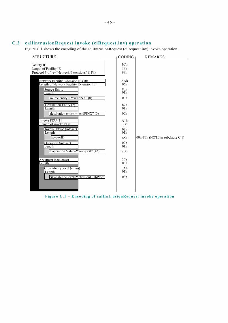
- 46 -
C.2 callintrusionRequest invoke (ciRequest.inv) operation Figure C.1 shows the encoding of the callIntrusionRequest (ciRequest.inv) invoke operation.
Facility IELength of Facility IEProtocol Profile=“Network Extensions” (1Fh)
Network Facility Extension IE (10)Length of Network Facility Extension IE
Source EntityLength
source entity = “endPINX” (0)
Destination Entity (2)Length
destination entity = “endPINX” (0)
Invoke PDU [1]Length of invoke PDU
InvokeIDtype (integer)Length
Length
Length
Length
InvokeID
Operation (integer)
0 operation Value=“ci-request” (43)
Argument (sequence)
CIcapabilityLevel (enum)
ciCapabilityLevel=“intrusionHighProt”
1Ch16h9Fh
AAh06h
00h01h80h
82h01h
02h0BhA1h
00h
02hxxh01h
01h2Bh
0Ah03h30h
03h01h
STRUCTURE CODING REMARKS
00h-FFh (NOTE in subclause C.1)
Figure C.1 – Encoding of cal lIntrusionRequest invoke operat ion
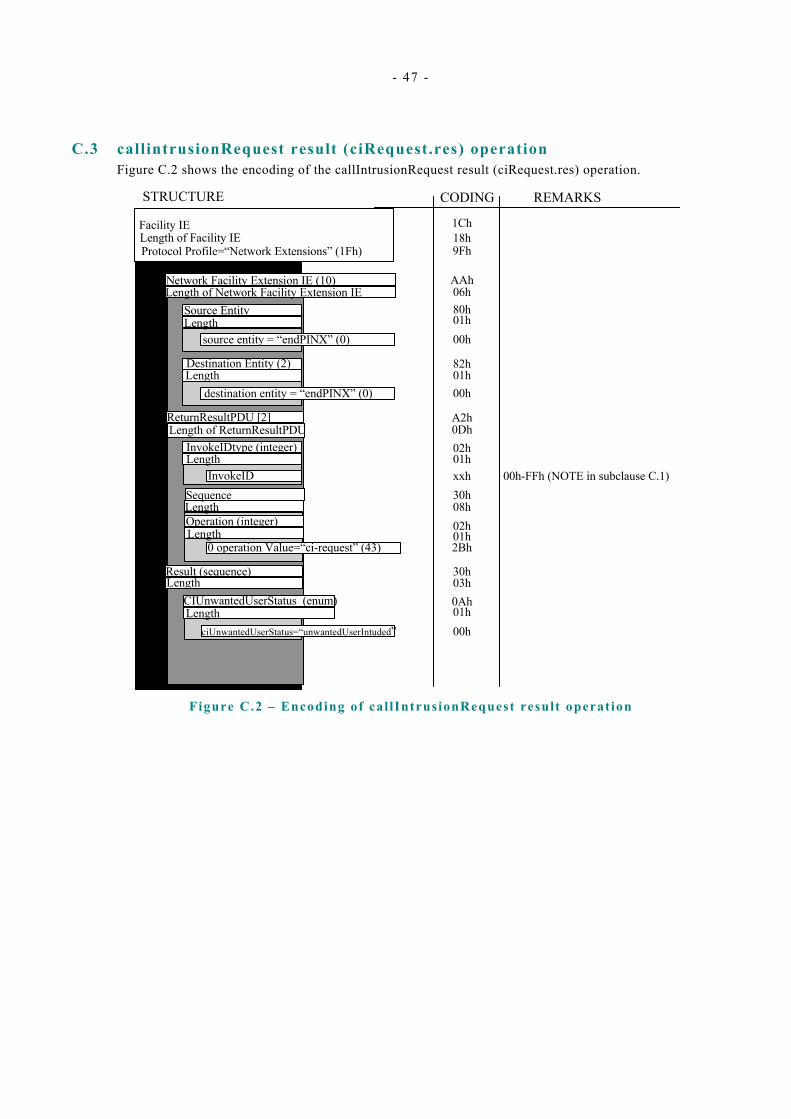
- 47 -
C.3 callintrusionRequest result (ciRequest.res) operation Figure C.2 shows the encoding of the callIntrusionRequest result (ciRequest.res) operation.
Facility IELength of Facility IEProtocol Profile=“Network Extensions” (1Fh)
Network Facility Extension IE (10)Length of Network Facility Extension IE
Source EntityLength
source entity = “endPINX” (0)
Destination Entity (2)Length
destination entity = “endPINX” (0)
ReturnResultPDU [2]Length of ReturnResultPDU
InvokeIDtype (integer)Length
Length
Length
Length
InvokeIDSequence
0 operation Value=“ci-request” (43)
Result (sequence)
CIUnwantedUserStatus (enum)
ciUnwantedUserStatus=“unwantedUserIntuded”
1Ch18h9Fh
AAh06h
00h01h80h
82h01h
02h0DhA2h
00h
30hxxh01h
01h02h08h
30h
2Bh
0Ah03h
STRUCTURE CODING REMARKS
Operation (integer) Length
01h00h
00h-FFh (NOTE in subclause C.1)
Figure C.2 – Encoding of cal lIntrusionRequest result operat ion

- 48 -
C.4 callintrusionGetCIPL invoke (ciGetCIPL.inv) operation Figure C.3 shows the encoding of the callIntrusionGetCIPL (ciGetCIPL.inv) invoke operation.
Facility IELength of Facility IEProtocol Profile=“Network Extensions” (1Fh)
Network Facility Extension IE (10)Length of Network Facility Extension IE
Source EntityLength
source entity = “endPINX” (0)
Destination Entity (2)Length
destination entity = “endPINX” (0)
Invoke PDU [1]Length of invoke PDU
InvokeIDtype (integer)Length
Length
Length
InvokeID
Operation (integer)
0 operation Value=“ci-getCIPL” (44)
Argument (null)
1Ch13h9Fh
AAh06h
00h01h80h
82h01h
02h08hA1h
00h
02hxxh01h
01h2Ch
00h05h
STRUCTURE CODING REMARKS
00h-FFh (NOTE in subclause C.1)
Figure C.3 – Encoding of cal lIntrusionGetCIPL invoke operat ion

- 49 -
C.5 callIntrusionGetCIPL result (ciGetCIPL.res) operation Figure C.4 shows the encoding of the callIntrusionGetCIPL result (ciGetCIPL.res) operation.
Facility IELength of Facility IEProtocol Profile=“Network Extensions” (1Fh)
Network Facility Extension IE (10)Length of Network Facility Extension IE
Source EntityLength
source entity = “endPINX” (0)
Destination Entity (2)Length
destination entity = “endPINX” (0)
ReturnResultPDU [2]Length of invoke PDU
InvokeIDtype (integer)Length
Length
Length
Length
InvokeID
Operation (intger)
0 operation Value=“ci-getCIPL” (44)
Result (sequence)
CIProtectionLevel (enum)
ciProtectionLevel
1Ch18h9Fh
AAh06h
00h01h80h
82h01h
02h0DhA2h
00h
30hxxh01h
01h02h
08h
30h
2Ch
0Ah03h
STRUCTURE CODING REMARKS
SequenceLength
01h
xxh
00h-FFh (NOTE in subclause C.1)
Figure C.4 – Encoding of cal lIntrusionGetCIPL result operation

- 50 -
C.6 callIntrusionCompleted invoke (ciCompleted.inv) operation Figure C.5 shows the encoding of the callIntrusionCompleted invoke (ciCompleted.inv) operation.
Facility IELength of Facility IEProtocol Profile=“Network Extensions” (1Fh)
Network Facility Extension IE (10)Length of Network Facility Extension IE
Source EntityLength
source entity = “endPINX” (0)
Destination Entity (2)Length
destination entity = “endPINX” (0)
Invoke PDU [1]Length of invoke PDU
InvokeIDtype (integer)Length
Length
Length
InvokeID
Operation (integer)
0 operation Value=“ci-complete” (48)
Argument (null)
1Ch16h9Fh
AAh06h
00h01h80h
82h01h
00h01h8Bh
00h
08hA1h
02hxxh
02h
01h
05h
30h
STRUCTURE CODING REMARKS
InterpretationApdu [11]Length
discardAnyUnrecognised (0)
01h
00h
00h-FFh (NOTE in subclause C.1)
Figure C.5 – Encoding of cal lIntrusionCompleted invoke operat ion
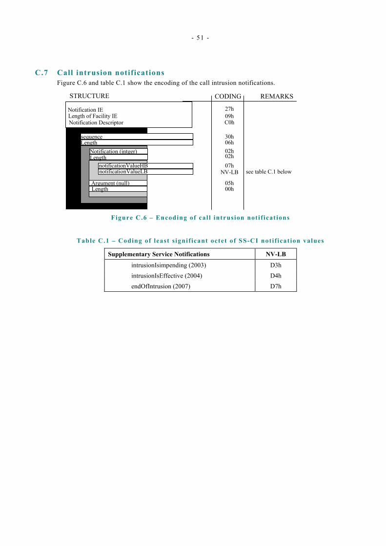
- 51 -
C.7 Call intrusion notifications Figure C.6 and table C.1 show the encoding of the call intrusion notifications.
Notification IELength of Facility IENotification Descriptor
sequenceLength
Notification (intger)Length
notificationValueHB
27h09hC0h
30h06h
07h02h02h
05h00h
STRUCTURE CODING REMARKS
see table C.1 below
Argument (null)Length
notificationValueLB NV-LB
Figure C.6 – Encoding of cal l intrusion noti f icat ions
Table C.1 – Coding of least s ignif icant octet of SS-CI not if icat ion values
Supplementary Service Notifications NV-LB
intrusionIsimpending (2003) D3h intrusionIsEffective (2004) D4h endOfIntrusion (2007) D7h
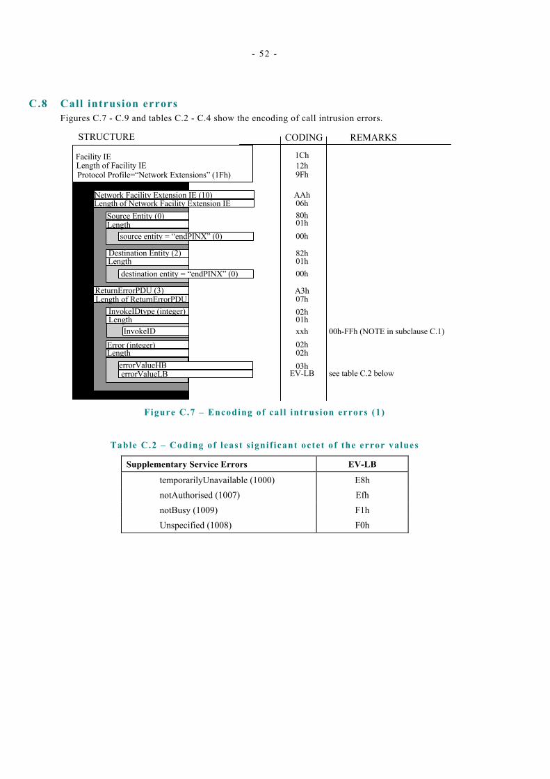
- 52 -
C.8 Call intrusion errors Figures C.7 - C.9 and tables C.2 - C.4 show the encoding of call intrusion errors.
Facility IELength of Facility IEProtocol Profile=“Network Extensions” (1Fh)
Network Facility Extension IE (10)Length of Network Facility Extension IE
Source Entity (0)Length
source entity = “endPINX” (0)
Destination Entity (2)Length
destination entity = “endPINX” (0)
ReturnErrorPDU (3)Length of ReturnErrorPDU
InvokeIDtype (integer)Length
Length
InvokeID
Error (integer)
errorValueHB
1Ch12h9Fh
AAh06h
00h01h80h
82h01h
02h07hA3h
00h
02hxxh01h
03h02h
EV-LB
STRUCTURE CODING REMARKS
errorValueLB see table C.2 below
00h-FFh (NOTE in subclause C.1)
Figure C.7 – Encoding of cal l intrusion errors (1)
Table C.2 – Coding of least s ignif icant octet of the error values
Supplementary Service Errors EV-LB
temporarilyUnavailable (1000) E8h notAuthorised (1007) Efh notBusy (1009) F1h Unspecified (1008) F0h
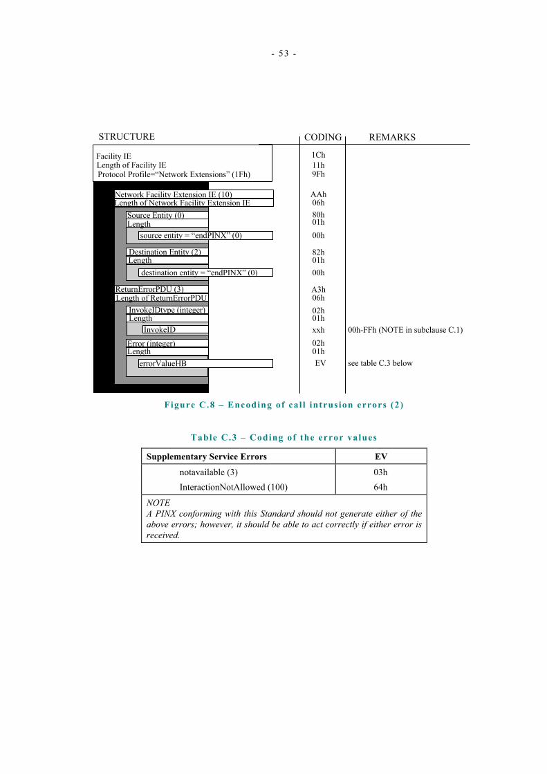
- 53 -
Facility IELength of Facility IEProtocol Profile=“Network Extensions” (1Fh)
Network Facility Extension IE (10)Length of Network Facility Extension IE
Source Entity (0)Length
source entity = “endPINX” (0)
Destination Entity (2)Length
destination entity = “endPINX” (0)
ReturnErrorPDU (3)Length of ReturnErrorPDU
InvokeIDtype (integer)Length
Length
InvokeID
Error (integer)
errorValueHB
1Ch11h9Fh
AAh06h
00h01h80h
82h01h
02h06hA3h
00h
02hxxh01h
01h EV
STRUCTURE CODING REMARKS
see table C.3 below
00h-FFh (NOTE in subclause C.1)
Figure C.8 – Encoding of cal l intrusion errors (2)
Table C.3 – Coding of the error values
Supplementary Service Errors EV
notavailable (3) 03h InteractionNotAllowed (100) 64h
NOTE A PINX conforming with this Standard should not generate either of the above errors; however, it should be able to act correctly if either error is received.
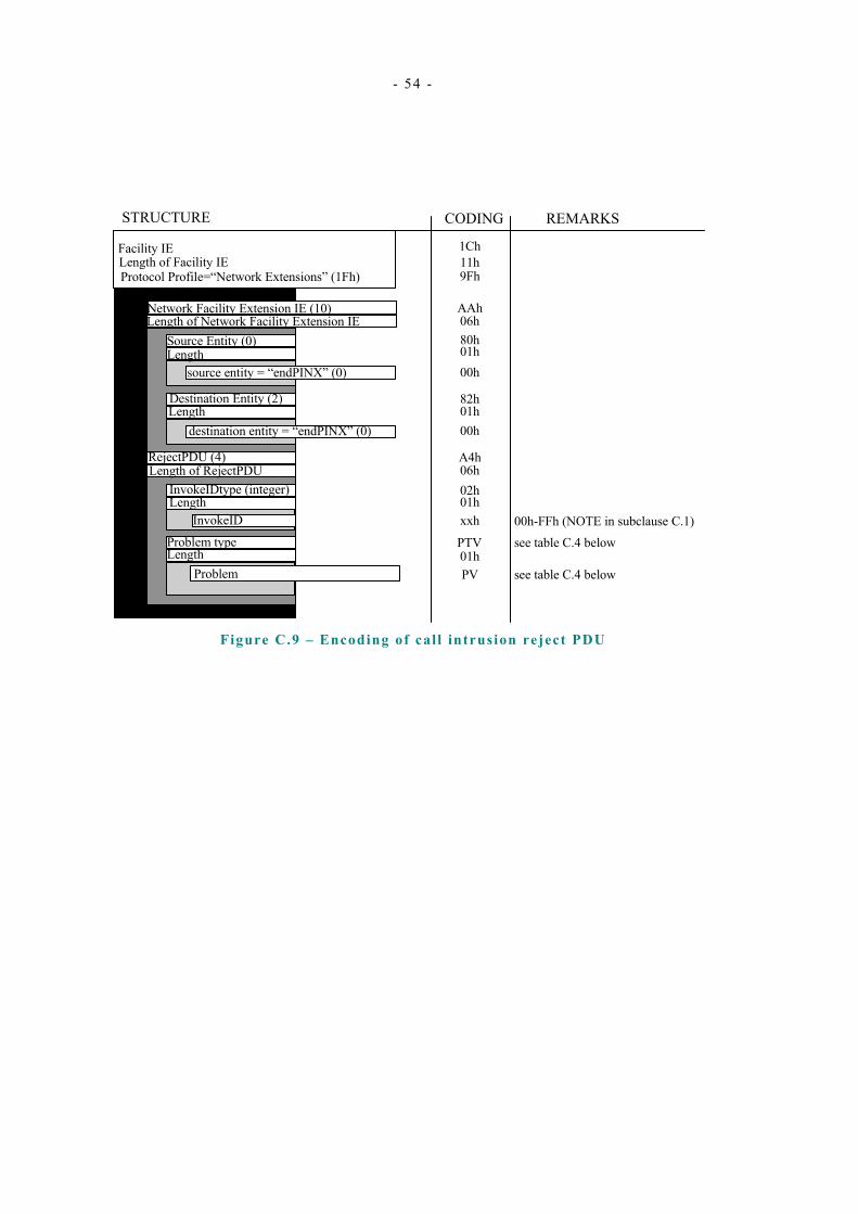
- 54 -
Facility IELength of Facility IEProtocol Profile=“Network Extensions” (1Fh)
Network Facility Extension IE (10)Length of Network Facility Extension IE
Source Entity (0)Length
source entity = “endPINX” (0)
Destination Entity (2)Length
destination entity = “endPINX” (0)
RejectPDU (4)Length of RejectPDU
InvokeIDtype (integer)Length
Length
InvokeID
Problem type
1Ch11h9Fh
AAh06h
00h01h80h
82h01h
02h06hA4h
00h
PTV
xxh01h
PV01h
STRUCTURE CODING REMARKS
see table C.4 belowProblem
see table C.4 below00h-FFh (NOTE in subclause C.1)
Figure C.9 – Encoding of cal l intrusion reject PDU

- 55 -
Table C.4 – Coding of the error values
Problem Type PTV PV
General Problem [0] 80h unrecognizedAPDU (0) 00h
mistypedAPDU (1) 01h unrecognisedAPDU (2) 02h
InvokeProblem1 81h DuplicatedInvocation (0) 00h unrecognisedOperation (1) 01h mistypedArgument (2) 02h resourceLimitation (3) 03h initiatorReleasing (4) 04h
ReturnResultProblem [2] 82h unrecognisedInvocation (0) 00h resultResponseUnexpected (1) 01h mistypedResult (2) 02h
ReturnErrorProblem [3] 83h unrecognisedInvocation (0) 00h resultResponseUnexpected (1) 01h unrecognisedError (2) 02h unexpectedError (3) 03h
NOTE A PINX conforming with this Standard should not generate any of the above errors; however, it should be able to act correctly if one of these errors is received.
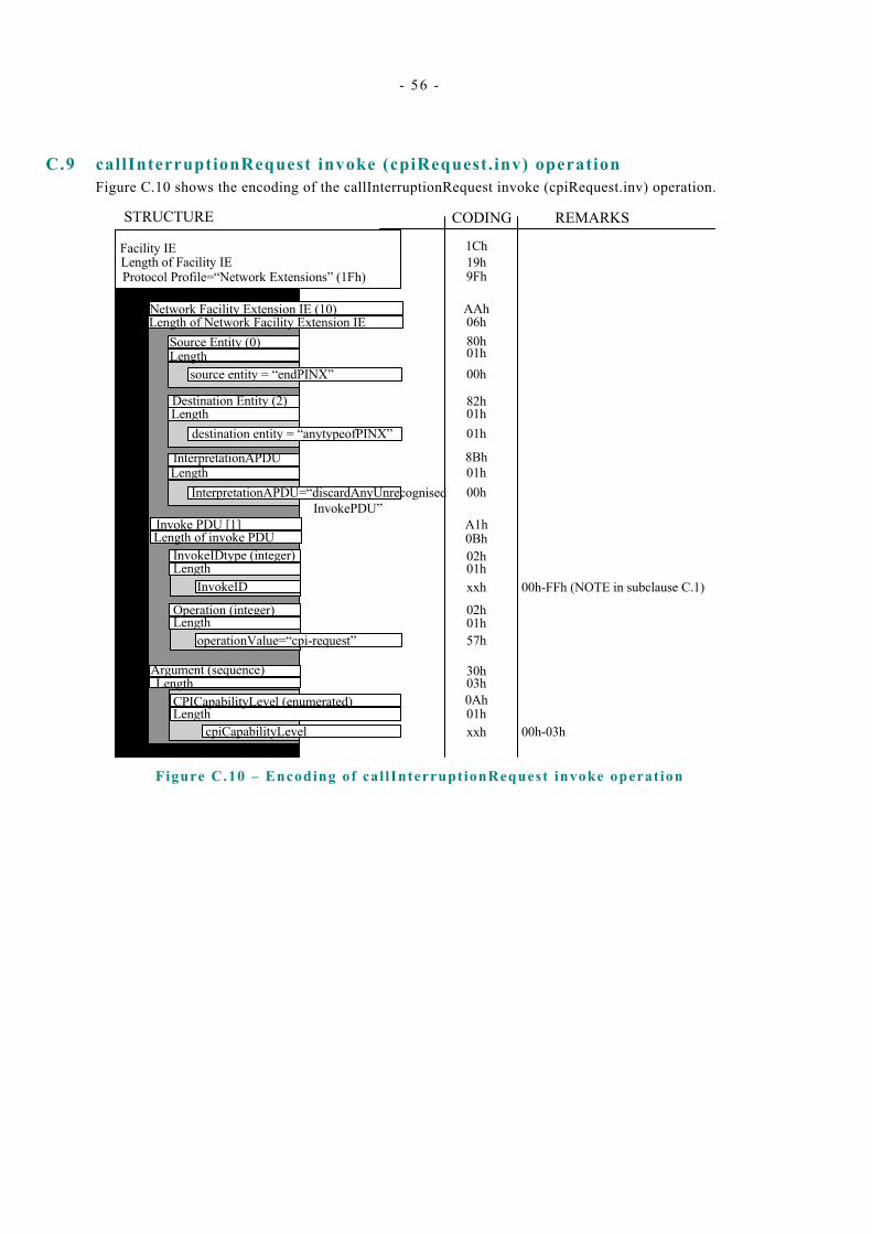
- 56 -
C.9 callInterruptionRequest invoke (cpiRequest.inv) operation Figure C.10 shows the encoding of the callInterruptionRequest invoke (cpiRequest.inv) operation.
Facility IELength of Facility IEProtocol Profile=“Network Extensions” (1Fh)
Network Facility Extension IE (10)Length of Network Facility Extension IE
Source Entity (0)Length
source entity = “endPINX”
Destination Entity (2)Length
destination entity = “anytypeofPINX”
Invoke PDU [1]Length of invoke PDU
InvokeIDtype (integer)Length
Length
InvokeID
Argument (sequence)
cpiCapabilityLevel
1Ch19h9Fh
AAh06h
00h01h80h
82h01h
02h0BhA1h
01h
xxh01h
30h
57h
02h
03h
xxh01h0Ah
STRUCTURE CODING REMARKS
01hLengthoperationValue=“cpi-request”
Operation (integer)
CPICapabilityLevel (enumerated)Length
00h-03h
LengthInterpretationAPDU=“discardAnyUnrecognised
InvokePDU”
01h00h
InterpretationAPDU 8Bh
00h-FFh (NOTE in subclause C.1)
Figure C.10 – Encoding of cal lInterruptionRequest invoke operat ion

- 57 -
C.10 callProtectionRequest invoke (cpipRequest.inv) operation Figure C.11 shows the encoding of the callProtectionRequest invoke (cpipRequest.inv) operation.
Facility IELength of Facility IEProtocol Profile=“Network Extensions” (1Fh)
Network Facility Extension IE (10)Length of Network Facility Extension IE
Source Entity (0)Length
source entity = “endPINX”
Destination Entity (2)Length
destination entity = “anytypeofPINX”
Invoke PDU [1]Length of invoke PDU
InvokeIDtype (integer)Length
Length
InvokeID
Argument (sequence)
cpiProtectionLevel
1Ch19h9Fh
AAh06h
00h01h80h
82h01h
02h0BhA1h
01h
xxh01h
30h
58h
02h
03h
xxh01h0Ah
STRUCTURE CODING REMARKS
01hLengthoperationValue=“cpi-request”
Operation (integer)
CPIProtectionLevel (enumerated)Length
00h-03h
Length 01h00h
InterpretationAPDU
InterpretationAPDU=“discardAnyUnrecognised InvokePDU”
8Bh
00h-FFh (NOTE in subclause C.1)
Figure C.11 – Encoding of cal lProtect ionRequest invoke operat ion

- 58 -
C.11 Call priority interruption notifications Figure C.12 and table C.5 show the encoding of call priority interruption notifications.
Notification IELength of Facility IENotification Descriptor
sequenceLength
Notification (intger)Length
notificationValueHB
27h09hC0h
30h06h
07h02h02h
05h00h
STRUCTURE CODING REMARKS
see table C.5 below
Argument (null)Length
notificationValueLB NV-LB
Figure C.12 – Encoding of cal l priority interruption noti f icat ions
Table C.5 – Coding of least s ignif icant octet of SS-CPI not if icat ion values
Call Priority Interruption (QSIG-CPI) NV-LB
interruptionIsImpending (2008) D8h interruptionTerminated (2009) D9h interruptionForcedRelease (2010) DAh

.

.

Free printed copies can be ordered from: ECMA 114 Rue du Rhône CH-1204 Geneva Switzerland
Fax: +41 22 849.60.01 Email: [email protected]
Files of this Standard can be freely downloaded from the ECMA web site (www.ecma.ch). This site gives full information on ECMA, ECMA activities, ECMA Standards and Technical Reports.

ECMA 114 Rue du Rhône CH-1204 Geneva Switzerland
See inside cover page for obtaining further soft or hard copies.