private integrated services network (pisn) - circuit...
TRANSCRIPT

Standard ECMA-143
4th Edition - December 2001
Standa rd i z ing In fo rma t ion and Commun ica t i on Sys t ems
Private Integrated Services Network (PISN) - Circuit Mode Bearer Services - Inter-Exchange Signalling Procedures and Protocol
Phone: +41 22 849 .60 .00 - Fax: +41 22 849 .60 .01 - URL: h t tp : / /www.ecma.ch - In ternet : he [email protected]

.
Standard ECMA-143
4th Edition - December 2001
Standa rd i z ing In fo rma t ion and Commun ica t i on Sys t ems
Private Integrated Services Network (PISN) - Circuit Mode Bearer Services - Inter-Exchange Signalling Procedures and Protocol
(QSIG-BC)
Phone: +41 22 849 .60 .00 - Fax: +41 22 849 .60 .01 - URL: h t tp : / /www.ecma.ch - In ternet : he [email protected] IW Ecma-143.doc 14-01-02 13,52

.
Brief History
This Standard is one of a series of ECMA Standards defining services and signalling protocols applicable to Private Integrated Services Networks (PISNs). The series uses ISDN concepts as developed by ITU-T and conforms to the framework of International Standards for Open Systems Interconnection as defined by ISO/IEC.
This particular Standard defines the signalling protocol for use at the Q-reference point in support of bearer circuit-switched services. The protocol defined in this Standard forms part of the PSS1 protocol (informally known as QSIG).
This Standard is based upon the practical experience of ECMA member companies and the results of their active and continuous participation in the work of ISO/IEC JTC1, ITU-T, ETSI and other international and national standardization bodies. It represents a pragmatic and widely based consensus.
Compared to the 2nd Edition of Standard ECMA-143 (published by ECMA in December 1992), the 3rd Edition had been extended to include support for Multi-rate and changes had been incorporated in order to achieve complete alignment with International Standard ISO/IEC 11572:1996(E) published by ISO/IEC in December 1996, including amendment 1 and 2, and defect report 001.
Compared to the 3rd Edition of Standard ECMA-143 (published by ECMA in June 1997), this 4th Edition is completely aligned with International Standard ISO/IEC 11572:2000(E) and corrigendum 001.
Adopted as 4th Edition of Standard ECMA-143 by the General Assembly of December 2001.

.
- i -
Table of contents
1 Scope 1
2 Conformance 1
3 References (normative) 1
4 Definit ions 1 4 .1 Pr ivate Integrated Services Network (PISN) 1 4 .2 Pr ivate Integrated services Network eXchange (PINX) 2 4 .3 Side , Incoming Side and Outgoing Side 2 4 .4 Outgoing Cal l and Incoming Cal l 2 4 .5 Originat ing PINX, Terminat ing PINX and Transi t PINX 2 4 .6 Gateway PINX, Incoming Gateway PINX and Outgoing Gateway PINX 2 4 .7 Preceding PINX and Subsequent PINX 3 4 .8 Inter-PINX l ink 3 4 .9 Route 3 4 .10 Signal l ing Carr iage Mechanism (SCM) 3 4 .11 Unrecognised message 3 4 .12 Unexpected message 3 4 .13 Unrecognised information e lement 3 4 .14 Informat ion elements with inval id contents 3
5 List of acronyms 4
6 General principles 4 6 .1 Protocol model 4 6 .2 Services provided to Cal l Control 5 6 .3 Services required of the Signal l ing Carr iage Mechanism 6
7 Protocol Control s tates 6 7 .1 States for c i rcui t -mode Cal l Control 6
7 .1 .1 Nul l Sta te (0) 6 7 .1 .2 Cal l In i t ia ted (1) 6 7 .1 .3 Over lap Sending (2) 6 7 .1 .4 Outgoing Cal l Proceeding (3) 6 7 .1 .5 Cal l Del ivered (4) 6 7 .1 .6 Cal l Present (6) 6 7 .1 .7 Cal l Received (7) 6 7 .1 .8 Connect Request (8) 7 7 .1 .9 Incoming Cal l Proceeding (9) 7 7 .1 .10 Act ive (10) 7 7 .1 .11 Disconnect Request (11) 7 7 .1 .12 Disconnect Indicat ion (12) 7 7 .1 .13 Release Request (19) 7

- i i -
7 .1 .14 Overlap Receiving (25) 7 7 .2 States for layer management 7
7 .2 .1 Null Sta te (Rest 0) 7 7 .2 .2 Restar t Request (Rest 1) 7 7 .2 .3 Restar t (Rest 2) 7
8 Call Control 7 8 .1 States for Transi t PINX Cal l Control 8
8 .1 .1 TCC_Idle (0) 8 8 .1 .2 TCC_Await Digi ts (1) 8 8 .1 .3 TCC_Await Addi t ional Digi ts (2) 8 8 .1 .4 TCC_Overlap (3) 8 8 .1 .5 TCC_Incoming Cal l Proceeding (4) 8 8 .1 .6 TCC_Transi t Cal l Proceeding (5) 8 8 .1 .7 TCC_Call Aler t ing (6) 8 8 .1 .8 TCC_Call Act ive (7) 8 8 .1 .9 TCC_Await Incoming Release (8) 9 8 .1 .10 TCC_Await Outgoing Release (9) 9 8 .1 .11 TCC_Await Two-Way Release (10) 9 8 .1 .12 TCC_Await Incoming Disconnect (11) 9 8 .1 .13 TCC_Await Outgoing Disconnect (12) 9 8 .1 .14 TCC_Await Two-Way Disconnect (13) 9
9 General procedures 9 9 .1 Use of the services of Signal l ing Carr iage Mechanism 9
9 .1 .1 Establ ishment of a Signal l ing Carr iage Mechanism connect ion 9 9 .1 .2 Transfer of data 9 9 .1 .3 Signal l ing Carr iage Mechanism reset 9 9 .1 .4 Signal l ing Carr iage Mechanism fai lure 9
9 .2 Handling of protocol er ror condi t ions 10 9 .2 .1 Protocol d iscr iminator er ror 10 9 .2 .2 Message too shor t 10 9 .2 .3 Cal l reference error 10 9 .2 .4 Message type or message sequence errors 10 9 .2 .5 General informat ion e lement errors 11 9 .2 .6 Mandatory informat ion e lement errors 11 9 .2 .7 Non-mandatory informat ion e lement errors 12 9 .2 .8 Signal l ing Carr iage Mechanism reset 13 9 .2 .9 Signal l ing Carr iage Mechanism fai lure 13
9 .3 Sta tus and s ta tus enquiry protocol procedures 14 9 .3 .1 Sta tus enquiry procedure 14 9 .3 .2 Receiving a STATUS message 14
10 Circuit-switched Cal l Control procedures 16 10.1 Cal l es tabl ishment 17
10.1 .1 Cal l request 17 10.1 .2 Information channel se lect ion 17
- i i i -
10 .1 .3 Over lap sending 18 10.1 .4 Cal l proceeding 18 10.1 .5 Cal l conf irmation indicat ion 19 10.1 .6 Cal l connected 20 10.1 .7 Use of the PROGRESS message 20 10.1 .8 Fai lure of cal l es tabl ishment 21
10.2 Cal l c lear ing 21 10.2 .1 Terminology 21 10.2 .2 Except ion condi t ions 21 10.2 .3 Clear ing 22 10.2 .4 Clear col l is ion 22
10.3 Cal l col l is ions 22 10.4 Transi t PINX Call Control requirements 23
10.4 .1 Receipt of address informat ion 23 10.4 .2 State TCC_Await_Digi ts 24 10.4 .3 State TCC_Await_Addit ional_Digi ts 24 10.4 .4 State TCC_Overlap 25 10.4 .5 Channel through connect ion procedures 26 10.4 .6 State TCC_Incoming_Cal l_Proceeding 26 10.4 .7 State TCC_Transi t_Cal l_Proceeding 27 10.4 .8 State TCC_Call_Aler t ing 28 10.4 .9 State TCC_Call_Active 28 10.4 .10 Cal l c lear ing a t a Transi t PINX 29 10.4 .11 Handl ing of Basic Cal l informat ion e lements a t a Transi t PINX 30
10.5 Originat ing PINX Call Control requirements 30 10.5 .1 Transmiss ion of the SETUP message 31 10.5 .2 Agreement of the informat ion channel 31 10.5 .3 Receipt of Progress indicators 31 10.5 .4 Receipt of ALERTING message 31 10.5 .5 Receipt of CONNECT message 32 10.5 .6 Cal l c lear ing in i t ia ted by the Originat ing PINX 32 10.5 .7 Receipt of an indicat ion of cal l c lear ing 32
10.6 Terminat ing PINX Call Control requirements 32 10.6 .1 Receipt of the SETUP message 32 10.6 .2 Transmiss ion of ALERTING message 33 10.6 .3 Transmiss ion of Progress indicators 33 10.6 .4 Transmiss ion of CONNECT message 33 10.6 .5 Cal l c lear ing in i t ia ted by the Terminat ing PINX 33 10.6 .6 Receipt of an indicat ion of cal l c lear ing 34
10.7 Incoming Gateway PINX Call Control requirements 34 10.7 .1 Transmiss ion of the SETUP message 34 10.7 .2 Interworking indicat ions in the SETUP Message 35 10.7 .3 Agreement of the informat ion channel 35 10.7 .4 Receipt of Progress indicators 35 10.7 .5 Receipt of ALERTING message 35 10.7 .6 Receipt of CONNECT message 36

- iv -
10.7 .7 Cal l c lear ing in i t ia ted by the Incoming Gateway PINX 36 10.7 .8 Receipt of an indicat ion of cal l c lear ing 36
10.8 Outgoing Gateway PINX Call Control requirements 37 10.8 .1 Receipt of the SETUP message 37 10.8 .2 Connect ion of the information channel 37 10.8 .3 Transmiss ion of in terworking indicat ions 37 10.8 .4 Transmiss ion of ALERTING message 38 10.8 .5 Transmiss ion of CONNECT message 38 10.8 .6 Cal l c lear ing in i t ia ted by the Outgoing Gateway PINX 39 10.8 .7 Receipt of an indicat ion of cal l c lear ing 39
11 Procedures for layer management 39 11.1 Restar t procedures 39
11.1 .1 Sending RESTART 39 11.1 .2 Receipt of RESTART 40 11.1 .3 Restar t col l is ion 40
12 Protocol t imers 40
13 Functional def init ion of messages 43 13.1 Messages for general procedures 43
13.1 .1 STATUS 43 13.1 .2 STATUS ENQUIRY 43
13.2 Messages for Circui t Mode Cal l Control 44 13.2 .1 ALERTING 44 13.2 .2 CALL PROCEEDING 44 13.2 .3 CONNECT 44 13.2 .4 CONNECT ACKNOWLEDGE 45 13.2 .5 DISCONNECT 45 13.2 .6 INFORMATION 45 13.2 .7 PROGRESS 45 13.2 .8 RELEASE 46 13.2 .9 RELEASE COMPLETE 46 13.2 .10 SETUP 46 13.2 .11 SETUP ACKNOWLEDGE 47
13.3 Messages for layer management 47 13.3 .1 RESTART 47 13.3 .2 RESTART ACKNOWLEDGE 47
14 General message format and coding of information elements 48 14.1 Overview 48 14.2 Protocol d iscr iminator 48 14.3 Cal l reference 49 14.4 Message type 50 14.5 Other information e lements for Basic Cal l control (codeset 0) 51
14.5 .1 Coding rules 51 14.5 .2 Extension of codesets 53

- v -
14.5 .3 Locking shif t procedure 54 14.5 .4 Non-locking shif t procedure 55 14.5 .5 Bearer capabi l i ty 55 14.5 .6 Cal l s ta te 57 14.5 .7 Cal led par ty number 58 14.5 .8 Cal led par ty subaddress 61 14.5 .9 Cal l ing par ty number 61 14.5 .10 Cal l ing par ty subaddress 62 14.5 .11 Cause 62 14.5 .12 Channel ident i f icat ion 67 14.5 .13 Connected number 70 14.5 .14 Connected subaddress 70 14.5 .15 High layer compat ib i l i ty ( layers 4-7) 71 14.5 .16 Low layer compat ib i l i ty ( layers 1-3) 71 14.5 .17 Progress indicator 71 14.5 .18 Restar t indicator 72 14.5 .19 Sending complete 73
14.6 Information e lements of codeset 5 73
Annex A - Protocol Implementat ion Conformance Statement (PICS) for ECMA-143 75
Annex B - Use of the cause information element 87
Annex C - Examples of message sequences 91
Annex D - Manufacturer specif ic information 95
Annex E - SDL diagram for the procedures over a symmetrical l ink between two peer PINX’s 97
Annex F - SDL diagram for the procedures on e ither s ide of a Transit -PINX 119
Annex G - Bibl iography 137
Annex ZA - Segmentat ion and reassembly procedures 139
Annex ZB - Addit ional progress descript ions 149

- v i -
.

1 Scope This Standard defines the signalling procedures and protocol for the purpose of circuit-switched Call Control at the Q-reference point between Private Integrated services Network eXchanges (PINXs) connected together within a Private Integrated Services Network (PISN).
The Q reference point is defined in ECMA-133.
This Standard is based upon that described in ITU-T Recommendation Q.931, including the provisions for symmetrical operation described in annex D of that recommendation.
Service specifications are produced in three stages and according to the method specified in ETS 300 387. This Standard contains the stage 3 specification for the Q reference point and satisfies the requirements identified by the stage 1 and stage 2 specifications in ECMA-142, ECMA-148 and ISO/IEC 11584.
This Standard is applicable to PINXs which interconnect to form a PISN.
2 Conformance In order to conform to this Standard, a PINX shall satisfy the requirements identified in the Protocol Implementation Conformance Statement (PICS) proforma in annex A.
3 References (normative) The following standards contain provisions which, through reference in this text, constitute provisions of this Standard. All standards are subject to revision, and parties to agreements based on this Standard are encouraged to investigate the possibility of applying the most recent editions of the standards indicated below.
In the case of references to ECMA Standards that are aligned with ISO/IEC International Standards, the number of the appropriate ISO/IEC International Standard is given in brackets after the ECMA reference.
ECMA-133 Private Integrated Services Network (PISN) - Reference Configuration for PISN Exchanges (PINX) (International Standard ISO/IEC 11579-1)
ECMA-155 Private Integrated Services Networks - Addressing (International Standard ISO/IEC 11571)
ISO/IEC 8886 Information technology - Open Systems Interconnection - Data link service definition (1996)
ETS 300 387 Private Telecommunication Network (PTN); Method for the specification of basic and supplementary services (1994)
ITU-T Rec. E.164 The international public telecommunication numbering plan (1997)
ITU-T Rec. I.330 ISDN numbering and addressing principles (Blue Book) (1988)
ITU-T Rec. Q.931 ISDN user-network interface layer 3 specification for basic call control (1998)
ITU-T Rec. T.50 Information technology - 7-bit coded character set for information interchange (1992)
4 Definitions For the purposes of this Standard, the following definitions apply.
4.1 Private Integrated Services Network (PISN) An ISDN providing services to a specific set of users (contrary to a public ISDN which provides services to the general public).
NOTE This definition does not include legal and regulatory aspects and does not indicate any aspects of ownership.
- 2 -
4.2 Private Integrated services Network eXchange (PINX) A PISN nodal entity which provides automatic connection handling functions used for the provision of telecommunication services based on the definitions of the public ISDN services.
A PISN nodal entity consists of one or more nodes.
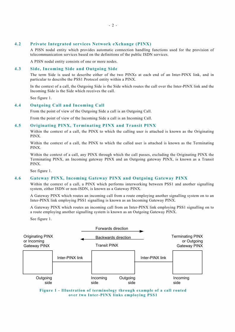
4.3 Side, Incoming Side and Outgoing Side The term Side is used to describe either of the two PINXs at each end of an Inter-PINX link, and in particular to describe the PSS1 Protocol entity within a PINX.
In the context of a call, the Outgoing Side is the Side which routes the call over the Inter-PINX link and the Incoming Side is the Side which receives the call.
See figure 1.
4.4 Outgoing Call and Incoming Call From the point of view of the Outgoing Side a call is an Outgoing Call.
From the point of view of the Incoming Side a call is an Incoming Call.
4.5 Originating PINX, Terminating PINX and Transit PINX Within the context of a call, the PINX to which the calling user is attached is known as the Originating PINX.
Within the context of a call, the PINX to which the called user is attached is known as the Terminating PINX.
Within the context of a call, any PINX through which the call passes, excluding the Originating PINX the Terminating PINX, an Incoming gateway PINX and an Outgoing gateway PINX, is known as a Transit PINX.
See figure 1.
4.6 Gateway PINX, Incoming Gateway PINX and Outgoing Gateway PINX Within the context of a call, a PINX which performs interworking between PSS1 and another signalling system, either ISDN or non-ISDN, is known as a Gateway PINX.
A Gateway PINX which routes an incoming call from a route employing another signalling system on to an Inter-PINX link employing PSS1 signalling is known as an Incoming Gateway PINX.
A Gateway PINX which routes an incoming call from an Inter-PINX link employing PSS1 signalling on to a route employing another signalling system is known as an Outgoing Gateway PINX.
See figure 1.
Forwards direction
Originating PINXor IncomingGateway PINX Transit PINX
Terminating PINXor Outgoing
Gateway PINX
Inter-PINX link Inter-PINX link
Outgoingside
Incomingside
Incomingside
Outgoingside
Backwards direction
Figure 1 - I l lustrat ion of terminology through example of a cal l routed
over two Inter-PINX l inks employing PSS1

- 3 -
4.7 Preceding PINX and Subsequent PINX Within the context of a call, from the point of view of a PINX acting as the Incoming Side of an Inter-PINX link, the PINX at the other end of the link, acting as the Outgoing Side, is known as the Preceding PINX.
Within the context of a call, from the point of view of a PINX acting as the Outgoing Side of an Inter-PINX link, the PINX at the other end of the link, acting as the Incoming Side, is known as the Subsequent PINX.
4.8 Inter-PINX link The totality of a signalling channel connecting two PINXs and the user information channels under the control of that signalling channel, as seen by each PINX.
NOTE An Inter-PINX link can be provided by various types of Signalling Carriage Mechanism involving different types of physical interface. The signalling and user information channels referred to in this Standard are independent of the channels or timeslots at a physical interface.
4.9 Route A number of user information channels at the Q reference point that have the same characteristics (e.g. transmission capacity, time sequence integrity).
4.10 Signall ing Carriage Mechanism (SCM) The infrastructure that transports messages between Protocol Control entities in two interconnected PINXs.
4.11 Unrecognised message An unrecognised message is defined as a message which is not specified in clause 13 of this Standard or in any other Standard relating to PSS1 Protocol to which the PINX claims conformance (e.g., a Standard specifying generic procedures for supplementary services).
NOTE The handling of national/private messages is outside the scope of this Standard (see annex D).
4.12 Unexpected message Within the context of a particular Protocol Control state, an unexpected message is a message which is recognised, but for which no procedures are defined in clauses 9.3 and 10, and annex ZA of this Standard (or in any other Standard relating to PSS1 Protocol to which the PINX claims conformance) for receipt in that Protocol Control state.
4.13 Unrecognised information element An unrecognised information element is defined as an information element received in a particular message which is not specified as part of that message in clause 13 of this Standard or in any other Standard relating to PSS1 Protocol to which the PINX claims conformance (e.g., a Standard specifying generic procedures for supplementary services).
NOTE The handling of national/private information elements is outside the scope of this Standard (see annex D).
4.14 Information elements with invalid contents An information element with invalid contents is defined as an information element which is recognised, but whose contents cannot be interpreted as valid using the rules specified in clause 14 of this Standard, or contains field values which are marked as “reserved” in clause 14 of this Standard.
NOTE The receipt of reserved codepoints in octets 5, 6, and 7 of a Bearer Capability information element, shall not be treated as having invalid contents (see clause 14.5.5).
- 4 -
5 List of acronyms ANF Additional Network Feature
DSS1 Digital Subscriber Signalling System Number 1
IE Information Element
ISDN Integrated Services Digital Network
MP Mapping (functional grouping)
PICS Protocol Implementation Conformance Statement
PISN Private Integrated Services Network
PINX Private Integrated services Network eXchange
PSS1 Private Integrated Signalling System Number 1
SCM Signalling Carriage Mechanism
TE Terminal Equipment
6 General principles The Basic Call is a single invocation of a basic service. This Standard specifies the signalling procedures for establishing, maintaining and clearing a circuit-mode Basic Call at an interface between two PINXs. These signalling procedures are defined in terms of messages exchanged over a Signalling Carriage Mechanism (SCM) connection within the signalling channel of the Inter-PINX link. The result of successful Basic Call establishment is a connection for the purpose of user information transfer. This connection uses a user information channel of the Inter-PINX link.
Throughout this Standard, the term user information channel is used to indicate any channel other than the signalling channel.
Conceptually, an Inter-PINX link is attached to a PINX at the Q-reference point, and comprises a signalling channel and one or more user information channels. In practice, these channels are provided by bearer services of an intervening network (ISDN or non-ISDN).
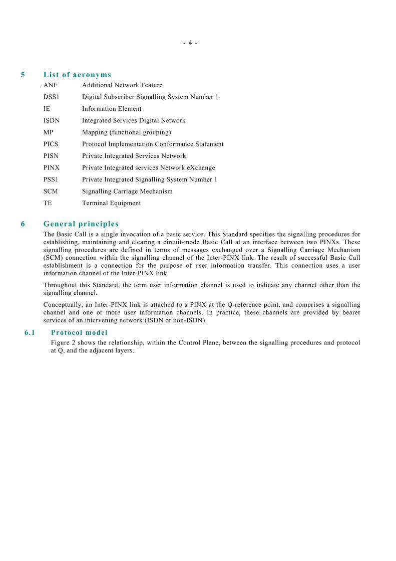
6.1 Protocol model Figure 2 shows the relationship, within the Control Plane, between the signalling procedures and protocol at Q, and the adjacent layers.
- 5 -
PSS1 Protocol Control
PSS1 Protocol Control
PINX to PINX Connection
PSS1 Protocol
Q
PSS1 Signalling Carriage
Mechanism
PSS1 Call
Control
PSS1 Call
Control
PSS1 Signalling Carriage
Mechanism
PSS1 Signalling Layer
Q
PSS1 Signalling Layer
Figure 2 - Control Protocol Model
The Protocol Control entity provides services to Call Control. Call Control corresponds to the Call Control functional entity identified for the Basic Call at Stage 2 (see ECMA-142). Primitives exchanged across the boundary between Call Control and Protocol Control correspond to the information flows exchanged between the Call Control functional entities, as identified at Stage 2. Protocol Control provides the mapping between these primitives and the messages transferred across the Inter-PINX link.
In order to transfer messages, Protocol Control uses the services of the Signalling Carriage Mechanism. The actual protocols visible at the C-reference point (see ECMA-133) are dependent upon the PINX interconnection scenario.
6.2 Services provided to Call Control Protocol Control provides services to Call Control whereby Call Control can send information flows to and receive information flows from the peer Call Control. A primitive from Call Control to Protocol Control of type “request” or “response” normally results in the associated information flow being presented to the peer Call Control as a primitive of type “indication” or “confirmation” respectively. The following primitives are used:
– SETUP-REQUEST/INDICATION/RESPONSE/CONFIRMATION for the establishment of a call;
– MORE_INFORMATION-REQUEST/INDICATION for requesting more destination addressing information during call establishment;
– INFORMATION-REQUEST/INDICATION for providing more destination addressing information during call establishment;
– PROCEED-REQUEST/INDICATION for indicating that sufficient destination addressing information has been received and call establishment is proceeding;
– ALERTING-REQUEST/INDICATION for indicating that the destination user is being alerted;
– PROGRESS-REQUEST/INDICATION for indicating interworking conditions and/or the availability of in-band patterns;
– REJECT-REQUEST/INDICATION for the immediate rejection of a call;
– DISCONNECT-REQUEST/INDICATION for the initiation of call release;
– RELEASE-REQUEST/INDICATION for the completion of call release;
- 6 -
– DL_RESET-INDICATION for indicating to Call Control that a SCM reset has occurred.
6.3 Services required of the Signall ing Carriage Mechanism The services required of the Signalling Carriage Mechanism can be defined in terms of the services provided by ISO/IEC 8886. Protocol Control uses the following acknowledged information transfer services and their associated primitives:
– Data transfer (i.e. Protocol Control message transfer), using the DL-DATA-REQUEST/INDICATION primitives;
– Establishment, using the DL-ESTABLISH-REQUEST/INDICATION/CONFIRM primitives;
– Termination, using the DL-RELEASE-REQUEST/INDICATION primitives.
NOTE An implementation is not constrained to use the ISO/IEC 8886 Protocol in order to provide these primitives.
7 Protocol Control states Protocol Control procedures for calls and layer management are specified in terms of:
a) messages which are transferred across the Inter-PINX link,
b) the primitives to and from Call Control at each PINX,
c) the information processing and actions that take place within Protocol Control at each PINX, and
d) the states that can exist within Protocol Control at each PINX.
State machines are deemed to exist for each circuit-mode call. Further state machines are deemed to exist for layer management.
7.1 States for circuit-mode Call Control The states below are used in association with call references other than the global call reference.
7.1 .1 Null State (0) No call exists.
7.1 .2 Cal l Init iated (1) This state exists for an outgoing call when the Outgoing Side has sent a request for call establishment to the Incoming Side but has not yet received a response.
7.1 .3 Overlap Sending (2) This state exists for an outgoing call when the Outgoing Side has received acknowledgement that the Incoming Side is able to receive additional call information in overlap mode.
7.1.4 Outgoing Cal l Proceeding (3) This state exists for an outgoing call when the Outgoing Side has received acknowledgement that the Incoming Side has received all call information necessary to effect call establishment.
7.1.5 Cal l Del ivered (4) This state exists for an outgoing call when the Outgoing Side has received from the Incoming Side an indication that the called user is being alerted.
7.1 .6 Call Present (6) This state exists for an incoming call when the Incoming Side has not yet responded to the request from the Outgoing Side for call establishment.
7.1.7 Cal l Received (7) This state exists for an incoming call when the Incoming Side has indicated to the Outgoing Side that the called user is being alerted.

- 7 -
7.1 .8 Connect Request (8) This state exists for an incoming call when the Incoming Side has indicated to the Outgoing Side that the called user has answered the call.
NOTE "answered" is the act of the end user accepting the call.
7.1.9 Incoming Cal l Proceeding (9) This state exists for an incoming call when the Incoming Side has sent to the Outgoing Side acknowledgement that it has received all call information necessary to effect call establishment.
7.1 .10 Act ive (10) This state exists for an incoming call when the Incoming Side has received from the Outgoing Side an acknowledgement of the indication that the called user has answered the call. This state exists for an outgoing call when the Outgoing Side has received from the Incoming Side an indication that the called user has answered the call.
NOTE "answered" is the act of the end user accepting the call.
7.1 .11 Disconnect Request (11) This state exists when a Side has sent to the other Side a request to disconnect the user information connection and is waiting for a response.
7.1 .12 Disconnect Indicat ion (12) This state exists when a Side has received from the other Side a request to disconnect the user information connection and has not yet responded.
7.1 .13 Release Request (19) This state exists when a Side has sent to the other Side a request to release the call and has not yet received a response.
7.1.14 Overlap Receiving (25) This state exists for an incoming call when the Incoming Side has sent acknowledgement to the Outgoing Side that it is able to receive additional call information in overlap mode.
7.2 States for layer management The states below are used in association with the global call reference.
7.2 .1 Null State (Rest 0) No transaction exists.
7.2 .2 Restart Request (Rest 1) This state exists for a restart transaction when the Side has sent a restart request to the other Side but has not yet received an acknowledgement.
7.2 .3 Restart (Rest 2) This state exists for a restart transaction when the Side has received a restart request from the other Side but has not yet sent an acknowledgement.
8 Call Control In addition to specifying Protocol Control, this Standard also specifies those aspects of Call Control which are necessary for PINXs to cooperate in the control of calls through a PISN. Although the behaviour of a Protocol Control entity with respect to a call is dependent on whether the PINX is the Outgoing Side or the Incoming Side of the Inter-PINX link, its behaviour is independent of whether the PINX is a Transit PINX, an End (Originating or Terminating) PINX, or a Gateway PINX. Call Control requirements, on the other hand, are dependent on whether the PINX is a Transit PINX, an Originating PINX, a Terminating PINX, an Incoming Gateway PINX or an Outgoing Gateway PINX.

- 8 -
Subclause 10.4 specifies the special Call Control requirements of a Transit PINX for coordinating the two Protocol Control entities. The requirements of subclause 10.4 are in addition to the requirements of Protocol Control, which are to be satisfied for both the Incoming Inter-PINX link and the Outgoing Inter-PINX link. An SDL representation of Call Control for a Transit PINX appears in annex F.
Subclause 10.5 specifies the special Call Control requirements for Originating PINXs. The requirements of subclause 10.5 are in addition to the requirements of Protocol Control, which are to be satisfied on the Outgoing Inter-PINX link.
Subclause 10.6 specifies the special Call Control requirements for Terminating PINXs. The requirements of subclause 10.6 are in addition to the requirements of Protocol Control, which are to be satisfied on the Incoming Inter-PINX link.
Subclause 10.7 specifies the special Call Control requirements for Incoming Gateway PINXs. The requirements of subclause 10.7 are in addition to the requirements of Protocol Control, which are to be satisfied on the Outgoing Inter-PINX link.
Clause 10.8 specifies the special Call Control requirements for Outgoing Gateway PINXs. The requirements of subclause 10.8 are in addition to the requirements of Protocol Control, which are to be satisfied on the Incoming Inter-PINX link.
8.1 States for Transit PINX Call Control The states below are used in association with calls in Call Control of a Transit PINX.
NOTE These states are used in order to describe the behaviour of the Transit PINX Call Control function. These internal states are a descriptive tool and are not intended to constrain implementations.
8.1 .1 TCC_Idle (0) No call exists.
8.1 .2 TCC_Await Digits (1) This state exists when Call Control has received a request for call establishment from the Preceding PINX and is awaiting additional call information in order to select a route to the Subsequent PINX.
8.1 .3 TCC_Await Addit ional Digits (2) This state exists when Call Control has sent a request for call establishment to the Subsequent PINX and is awaiting possible additional call information from the Preceding PINX.
8.1 .4 TCC_Overlap (3) This state exists when Call Control is awaiting possible additional call information from the Preceding PINX, having received acknowledgement that the Subsequent PINX is able to receive additional call information in overlap mode.
8.1.5 TCC_Incoming Cal l Proceeding (4) This state exists when Call Control has determined that it has received all call information necessary to effect call establishment and has informed the Preceding PINX, but no response to the request for call establishment has been received from the Subsequent PINX.
8.1.6 TCC_Transit Cal l Proceeding (5) This state exists when Call Control has received from the Subsequent PINX a response to the request for call establishment and is no longer expecting additional call information to pass to the Subsequent PINX in overlap mode.
8.1 .7 TCC_Call Alert ing (6) This state exists when Call Control has received from the Subsequent PINX an indication that the called user is being alerted and has relayed the indication on to the Preceding PINX.
8.1 .8 TCC_Call Act ive (7) This state exists when Call Control has received from the Subsequent PINX and relayed on to the Preceding PINX an indication that the called user has answered the call.
- 9 -
NOTE "answered" is the act of the end user accepting the call.
8.1 .9 TCC_Await Incoming Release (8) This state exists when Call Control has initiated call clearing towards the Preceding PINX and is awaiting an acknowledgement.
8.1 .10 TCC_Await Outgoing Release (9) This state exists when Call Control has initiated call clearing towards the Subsequent PINX and is awaiting an acknowledgement.
8.1 .11 TCC_Await Two-Way Release (10) This state exists when Call Control has initiated call clearing towards the Preceding PINX and towards the Subsequent PINX and is awaiting an acknowledgement from each.
8.1 .12 TCC_Await Incoming Disconnect (11) This state exists when Call Control has applied an in-band tone or announcement towards the Preceding PINX and is awaiting the initiation of clearing procedures.
8.1 .13 TCC_Await Outgoing Disconnect (12) This state exists when Call Control has applied an in-band tone or announcement towards the Subsequent PINX and is awaiting the initiation of clearing procedures.
8.1 .14 TCC_Await Two-Way Disconnect (13) This state exists when Call Control has applied an in-band tone or announcement towards both the Preceding PINX and the Subsequent PINX and is awaiting the initiation of clearing procedures.
9 General procedures 9.1 Use of the services of Signall ing Carriage Mechanism
This clause specifies the use by PSS1 of the services of the Signalling Carriage Mechanism.
NOTE The SCM provides a defined service of quality.
9.1 .1 Establ ishment of a Signal l ing Carriage Mechanism connect ion Before the procedures for Call Control, layer management or any of the general procedures in clauses 9.2, 9.3 and annex ZA can be performed, a SCM connection shall be established. If a SCM connection has not already been established, Protocol Control shall request establishment by sending a DL-ESTABLISH-REQUEST primitive to the Signalling Carriage Mechanism. Receipt of a DL-ESTABLISH-CONFIRMATION primitive or a DL-ESTABLISH-INDICATION primitive from the Signalling Carriage Mechanism indicates that a SCM connection has been established.
9.1 .2 Transfer of data A PSS1 message (or message segment) is transmitted by including it with a DL-DATA-REQUEST primitive to the Signalling Carriage Mechanism.
A PSS1 message (or message segment) appears included with a DL-DATA-INDICATION primitive from the Signalling Carriage Mechanism.
9.1 .3 Signal l ing Carriage Mechanism reset Receipt of a DL-ESTABLISH-INDICATION primitive from the Signalling Carriage Mechanism subsequent to establishment of the SCM connection indicates a spontaneous SCM reset. The procedures specified in subclause 9.2.8 shall apply.
9.1 .4 Signal l ing Carriage Mechanism fai lure Receipt of a DL-RELEASE-INDICATION primitive from the SCM indicates a SCM malfunction. The procedures specified in subclause 9.2.9 shall apply.

- 10 -
9.2 Handling of protocol error conditions The procedures of clauses 9.3, 10, 11 and 12 of this specification are applicable only to those messages which pass the checks described in subclauses 9.2.1 through 9.2.7.
Subclauses 9.2.1 through 9.2.7 are listed in order of precedence.
9.2.1 Protocol discriminator error When a message is received with a protocol discriminator not in accordance with subclause 14.2, that message shall be ignored. “Ignore” means to do nothing, as if the message had never been received.
9.2 .2 Message too short When a message is received that is too short to contain a complete message type information element, that message shall be ignored.
9.2.3 Cal l reference error 9 .2 .3 .1 Inval id cal l reference format
If the Call reference information element octet 1, bits 5 through 8 do not equal “0000”, then the message shall be ignored.
If octet 1, bits 1 through 4 of the call reference information element indicates a length greater than the maximum length supported by the receiving equipment, then the message shall be ignored.
If a message containing the Dummy call reference is received, except when used in the context of other Standards which define its use, the message shall be ignored.
9.2.3 .2 Cal l reference procedural errors Whenever any message except SETUP, STATUS, RELEASE or RELEASE COMPLETE is received specifying a call reference (other than the global call reference) which is not recognised as relating to an active call or to a call in progress, the receiving entity shall send a RELEASE COMPLETE message and remain in the null state. The RELEASE COMPLETE message shall contain the call reference of the received message and cause number 81, “invalid call reference value”.
Alternatively, the receiving entity may send a RELEASE message (in place of the RELEASE COMPLETE message) in this situation, but this is not the preferred option. The RELEASE message shall contain the call reference of the received message and cause number 81, “invalid call reference value”.
When a SETUP message is received specifying a call reference which is not recognised as relating to an active call or to a call in progress, and with a call reference flag incorrectly set to ONE, this message shall be ignored.
When a STATUS message is received specifying a call reference which is not recognised as relating to an active call or to a call in progress, the procedures of subclause 9.3.2 shall apply.
When a RELEASE message is received specifying a call reference which is not recognised as relating to an active call or to a call in progress, the receiving entity shall send a RELEASE COMPLETE message. The RELEASE COMPLETE message shall contain the call reference of the received message and cause number 81, “invalid call reference value”.
When a RELEASE COMPLETE message is received specifying a call reference which is not recognised as relating to an active call or to a call in progress, no action shall be taken.
When a SETUP message is received specifying a call reference which is recognised as relating to an active call or to a call in progress, this SETUP message shall be ignored.
When any message except RESTART, RESTART ACKNOWLEDGE or STATUS is received specifying the global call reference, no action shall be taken on this message and a STATUS message specifying the global call reference with cause number 81 “invalid call reference value” shall be returned.
9.2.4 Message type or message sequence errors Whenever an unrecognised or unexpected message is received in any state other than the Null state, a STATUS message shall be returned with a cause information element. The cause value used shall be

- 11 -
number 98 “message not compatible with call state or message type non-existing or not implemented”. If the receiving entity can distinguish between unimplemented (or non-existing) message types and implemented message types which are incompatible with the call state, then the cause used shall be:
– cause number 97 “message type non-existing or not implemented”; or
– cause number 101 “message type not compatible with the call state”
Alternatively, a STATUS ENQUIRY message may be sent requesting the Protocol Control state of the peer entity.
There are two exceptions where a STATUS or STATUS ENQUIRY message shall not be sent. The first exception is when the outgoing or incoming side receives an unexpected RELEASE message (e.g., if the DISCONNECT message was corrupted by undetected transmission errors). In this case the receiving entity shall: disconnect and release the information channel; return RELEASE COMPLETE message to the originator; release the call reference; stop all timers; enter the Null state; and inform Call Control.
The second exception is when the outgoing or incoming side receives an unexpected RELEASE COMPLETE message. In this case, the receiving entity shall: disconnect and release the information channel; release the call reference; stop all timers; enter the Null state; and inform Call Control.
9.2.5 General information element errors 9 .2 .5 .1 Duplicated information elements
If an information element is repeated in a message more times than is permitted for that particular message, only the contents of the occurrences of that information element up to the limit of repetitions shall be handled. All subsequent occurrences of the element shall be ignored.
9.2.5 .2 Information elements exceeding maximum length Information elements with a length exceeding the maximum length (given in clause 14) shall be treated as information elements with content error.
9.2.5 .3 Information elements out of sequence If a variable length information element is received out of sequence (i.e. its code value is lower than that of the previous variable length information element) the receiving entity may ignore this information element and continue to process the message.
NOTE If the information element is mandatory and the receiver chooses to ignore the element, the error handling procedures of 9.2.6.1 will be followed. If the ignored information element is non-mandatory, the receiver will continue to process the message.
Some implementations may choose to process all the information elements received, regardless of the order in which they are received.
9.2.6 Mandatory information element errors 9 .2 .6 .1 Mandatory information element miss ing
When a message other than SETUP, DISCONNECT, RELEASE, or RELEASE COMPLETE is received which has one or more mandatory information elements missing, no action shall be taken on the message and no state change shall occur. A STATUS message shall then be returned with cause number 96 “mandatory information element is missing”.
When a SETUP message is received which has one or more mandatory information elements missing, a RELEASE COMPLETE message with cause number 96 “mandatory information element is missing” shall be returned.
When a DISCONNECT message is received with one or more mandatory information elements missing, the actions taken shall be the same as if a DISCONNECT message with cause number 31 “normal, unspecified” was received (see clause 10.2), with the exception that the RELEASE message returned shall contain cause number 96 “mandatory information element missing”.
When a RELEASE message is received as the first clearing message with one or more mandatory information elements missing the actions taken shall be the same as if a RELEASE message with cause number 31 “normal, unspecified” was received (see subclause 10.2), except that if a RELEASE
- 12 -
COMPLETE message is sent it shall contain cause number 96 “mandatory information element is missing”.
When a RELEASE COMPLETE message is received as the first clearing message, with one or more mandatory information elements missing, it shall be assumed that a RELEASE COMPLETE message was received with cause number 31 “normal, unspecified”.
9.2.6 .2 Mandatory information element content error When a message other than SETUP, DISCONNECT, RELEASE, or RELEASE COMPLETE is received which has one or more mandatory information elements with invalid content, no action shall be taken on the message and no state change shall occur. A STATUS message shall then be returned with cause number 100 “invalid information element contents”.
When a SETUP message is received which has one or more mandatory information elements with invalid content, a RELEASE COMPLETE message with cause number 100 “invalid information element contents” shall be returned.
When a DISCONNECT message is received with invalid content of the cause information element, the actions taken shall be the same as if a DISCONNECT message with cause number 31 “normal, unspecified” was received (see subclause 10.2.), with the exception that the RELEASE message returned shall contain cause number 100 “invalid information element contents”.
When a RELEASE message is received with invalid content of the cause information element, the actions taken shall be the same as if a RELEASE message with cause number 31 “normal, unspecified” was received (see subclause 10.2), except that if a RELEASE COMPLETE message is sent, it shall contain cause number 100 “invalid information element contents”.
When a RELEASE COMPLETE message is received with invalid content of the cause information element, it shall be assumed that a RELEASE COMPLETE message was received with cause number 31 “normal, unspecified”.
9.2.7 Non-mandatory information element errors 9 .2 .7 .1 Non-mandatory information e lement not recognised
When a message is received which has one or more non-mandatory information elements which are unrecognised, the receiving entity shall check whether they indicate “comprehension required” (refer to table 22 for the information element identifiers reserved with this meaning). If any information element is encoded to indicate “comprehension required” then the procedures in subclause 9.2.6.1 shall apply.
If all unrecognised information elements are not encoded to indicate “comprehension required”, the following actions shall apply:
– The receiving entity shall take action on the message and on those information elements which are recognised and have valid content;
– When the received message is other than a DISCONNECT, RELEASE or RELEASE COMPLETE, a STATUS message may be returned containing one Cause information element. The Cause information element shall contain cause number 99 “information element non-existent or not implemented”, and the diagnostic field, if present, shall contain the unrecognised information element identifier for each information element that is unrecognised. The STATUS message shall indicate the call state which the receiving entity enters after processing the message in which the unrecognised information element was received.
– If a DISCONNECT message is received with one or more unrecognised information elements, the actions taken shall be the same as if a DISCONNECT message was received without these unrecognised information elements (see subclause 10.2) with the exception that the RELEASE message returned shall contain cause number 99 “information element non-existent or not implemented”. This cause information element may contain a diagnostic field which shall contain the information element identifier for each unrecognised information element.
– If a RELEASE message is received with one or more unrecognised information elements, the actions taken shall be the same as if a RELEASE message was received without these unrecognised information elements (see subclause 10.2) with the exception that the RELEASE
- 13 -
COMPLETE message returned shall contain cause number 99 “information element non-existent or not implemented”. This cause information element may contain a diagnostic field which shall contain the information element identifier for each unrecognised information element.
– If a RELEASE COMPLETE message is received with one or more unrecognised information elements, the actions taken shall be the same as if a RELEASE COMPLETE message without those unrecognised information elements was received.
9.2 .7 .2 Non-mandatory information element content error When a message other than DISCONNECT, RELEASE or RELEASE COMPLETE is received which has one or more non-mandatory information elements with invalid content, action shall be taken on the message and those information elements which are recognised and have valid content. A STATUS message may be returned containing a cause information element with cause number 100 “invalid information element contents”, and the diagnostic field, if present, shall contain the information element identifier for each information element with invalid content. The STATUS message shall indicate the call state which the receiving entity enters after processing the message in which the information element content error was received.
If a DISCONNECT, RELEASE or RELEASE COMPLETE message is received which has one or more non-mandatory information elements with invalid content, normal call clearing procedures (defined in subclause 10.2) shall apply.
9.2 .8 Signal l ing Carriage Mechanism reset Whenever Protocol Control is informed of a spontaneous SCM reset by means of the DL-ESTABLISH-INDICATION primitive, the following procedures shall apply:
– for calls in the Overlap Sending state and the Overlap Receiving state, the entity shall initiate clearing by sending a DISCONNECT message with cause number 41 “Temporary Failure”, and following the procedures of clause 10.2.
– for calls in the disestablishment phase (states 11, 12, and 19) no action shall be taken.
– calls in the establishment phase (states 1, 3, 4, 6, 7, 8, and 9) and in the Active state shall be maintained. Optionally, a STATUS message may also be sent to report the current Protocol Control state to the peer entity or a STATUS ENQUIRY message may be sent to verify the Protocol Control state of the peer entity.
9.2 .9 Signal l ing Carriage Mechanism fai lure Whenever Protocol Control is notified by its Signalling Carriage Mechanism entity via the DL-RELEASE-INDICATION primitive that there is a SCM malfunction, the following procedure shall apply:
– any calls not in the active state shall be cleared internally. For any call in the active state, timer T309 shall be started.
If timer T309 is already running, it shall not be restarted.
– the PSS1 entity shall request SCM re-establishment by sending a DL-ESTABLISH-REQUEST primitive.
When informed of SCM re-establishment by means of the DL-ESTABLISH-CONFIRMATION primitive, the following procedure shall apply, for each active call:
– timer T309 shall be stopped;
– either: the PSS1 entity shall send a STATUS message to report the current Protocol Control state to the peer entity, or the PSS1 entity shall perform the status enquiry procedure to verify the Protocol Control state of the peer entity.
Cause number 31 “normal, unspecified” is recommended to be used in the STATUS message.
If timer T309 expires prior to SCM re-establishment, Protocol Control shall: release all resources; release the call reference; and enter the Null state. Call Control shall be informed of the failure of the call.
- 14 -
9.3 Status and status enquiry protocol procedures 9.3 .1 Status enquiry procedure
Whenever Protocol Control wants to check the correctness of a Protocol Control state at a peer PSS1 entity, a STATUS ENQUIRY message may be sent requesting the Protocol Control state.
Upon sending the STATUS ENQUIRY message, timer T322 shall be started in anticipation of receiving a STATUS message. While timer T322 is running, only one outstanding request for Protocol Control state shall exist. Therefore if timer T322 is already running, it shall not be restarted. If a clearing message is received before timer T322 expires, timer T322 shall be stopped, and the call clearing shall continue.
Upon receipt of a STATUS ENQUIRY message, the receiving entity shall respond with a STATUS message, reporting the current Protocol Control state and containing cause number 30 “responding to STATUS ENQUIRY”. Receipt of the STATUS ENQUIRY message shall not result in a state change.
The sending or receipt of the STATUS message in such a situation will not directly affect the Protocol Control state of either the sending or receiving entity. The side having received the STATUS message shall inspect the cause information element. If the STATUS message contains any cause other than cause number 30 “responding to STATUS ENQUIRY”, timer T322 shall continue to time for an explicit response to the STATUS ENQUIRY message.
If a STATUS message is received that contains cause number 30 “response to STATUS ENQUIRY” the timer T322 shall be stopped, and the “appropriate actions” shall be taken.
These “appropriate actions” are implementation dependent. However, the actions prescribed in 9.3.2 below shall apply.
If the sender’s Protocol Control state changes after STATUS ENQUIRY has been sent, this shall be taken into account when checking for a compatible Protocol Control state in the received STATUS message.
If timer T322 expires, and no STATUS message was received, the STATUS ENQUIRY message may be transmitted a number of times until a response is received.
The number of times the STATUS ENQUIRY message may be retransmitted is a implementation dependent value. If the limit is exceeded, that call shall be cleared. The cause that should be used when clearing in this situation is cause number 41 “temporary failure”. Call Control shall be notified of the failure of the call.
If T322 expires and a STATUS message, with a cause value other than number 30 “response to STATUS ENQUIRY”, was received the actions taken shall be an implementation option, which may be to process the received Protocol Control state in the same way as if the cause in the received STATUS message was number 30 “response to STATUS ENQUIRY”.
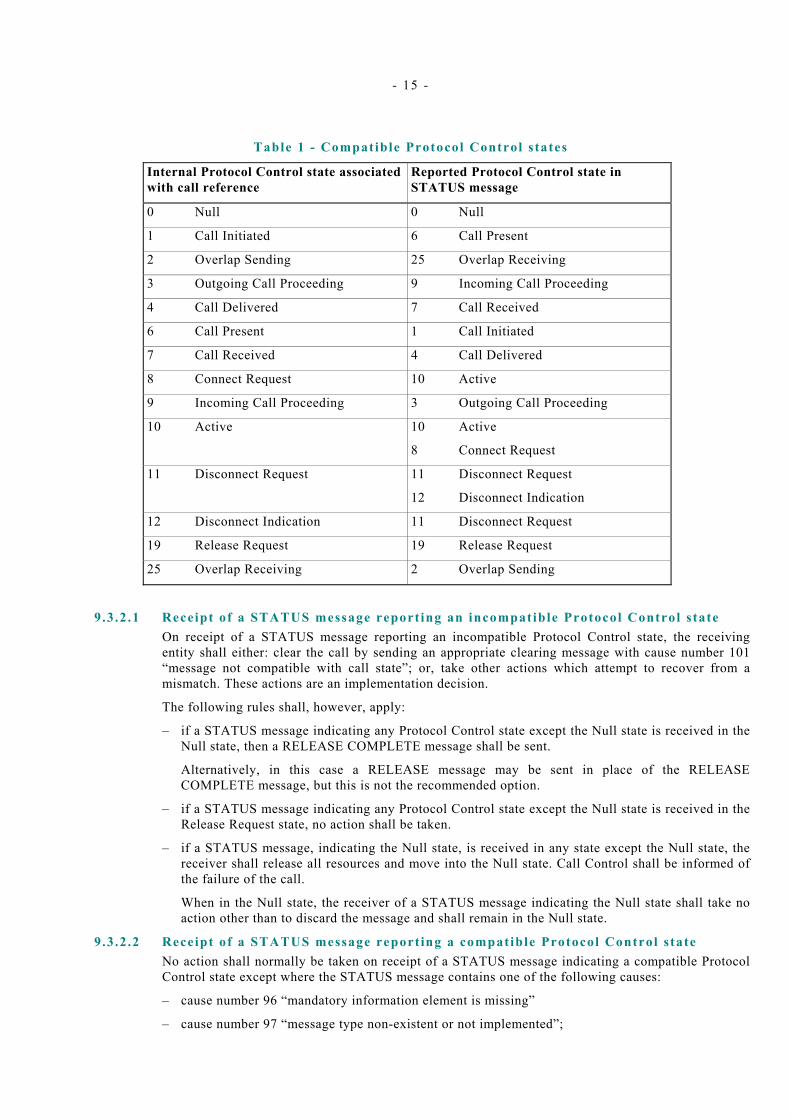
9.3.2 Receiving a STATUS message On receipt of a STATUS message containing a call reference value other than the Global Call Reference, the receiving entity shall check whether the Protocol Control state reported in the STATUS message is compatible with the state associated with that call reference internally. Table 1 indicates which Protocol Control states shall be considered compatible.
- 15 -
Table 1 - Compatible Protocol Control s tates
Internal Protocol Control state associated with call reference
Reported Protocol Control state in STATUS message
0 Null 0 Null
1 Call Initiated 6 Call Present
2 Overlap Sending 25 Overlap Receiving
3 Outgoing Call Proceeding 9 Incoming Call Proceeding
4 Call Delivered 7 Call Received
6 Call Present 1 Call Initiated
7 Call Received 4 Call Delivered
8 Connect Request 10 Active
9 Incoming Call Proceeding 3 Outgoing Call Proceeding
10 Active 10 Active
8 Connect Request
11 Disconnect Request 11 Disconnect Request
12 Disconnect Indication
12 Disconnect Indication 11 Disconnect Request
19 Release Request 19 Release Request
25 Overlap Receiving 2 Overlap Sending
9.3.2 .1 Receipt of a STATUS message report ing an incompatible Protocol Control s tate On receipt of a STATUS message reporting an incompatible Protocol Control state, the receiving entity shall either: clear the call by sending an appropriate clearing message with cause number 101 “message not compatible with call state”; or, take other actions which attempt to recover from a mismatch. These actions are an implementation decision.
The following rules shall, however, apply:
– if a STATUS message indicating any Protocol Control state except the Null state is received in the Null state, then a RELEASE COMPLETE message shall be sent.
Alternatively, in this case a RELEASE message may be sent in place of the RELEASE COMPLETE message, but this is not the recommended option.
– if a STATUS message indicating any Protocol Control state except the Null state is received in the Release Request state, no action shall be taken.
– if a STATUS message, indicating the Null state, is received in any state except the Null state, the receiver shall release all resources and move into the Null state. Call Control shall be informed of the failure of the call.
When in the Null state, the receiver of a STATUS message indicating the Null state shall take no action other than to discard the message and shall remain in the Null state.
9.3.2 .2 Receipt of a STATUS message report ing a compatible Protocol Control s tate No action shall normally be taken on receipt of a STATUS message indicating a compatible Protocol Control state except where the STATUS message contains one of the following causes:
– cause number 96 “mandatory information element is missing”
– cause number 97 “message type non-existent or not implemented”;
- 16 -
– cause number 99 “information element non-existent or not implemented”; or,
– cause number 100 “invalid information element contents”.
In these cases, the actions to be taken are an implementation option. The receiving entity should attempt to analyse the contents of the received STATUS message considering the current stage of the call in order to determine whether or not the call can continue. If successful analysis and recovery are not possible, the call may be cleared as described in subclause 10.2.
NOTE To improve interworking between implementations that support the requirements of ECMA-165 and implementations that do not, it is recommended that the diagnostic field should be included in the Cause information element when sending a STATUS message with cause values 97 or 100. It is also recommended that a call should not be cleared on receipt of a STATUS message containing either of these cause values. Implementations that do not support ECMA-165 will normally return a STATUS message on receipt of a message or information element defined in ECMA-165. The clearing of the call in such situations should not be the normal behaviour.
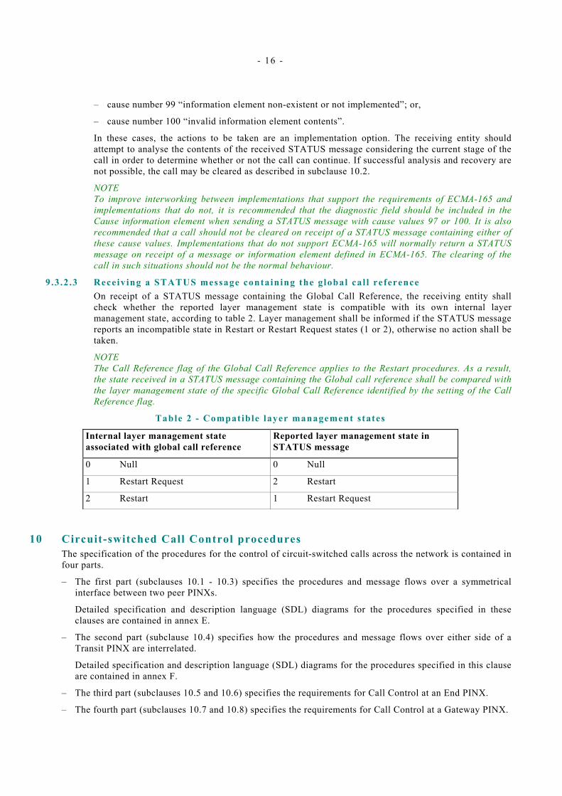
9.3.2 .3 Receiving a STATUS message containing the global cal l reference On receipt of a STATUS message containing the Global Call Reference, the receiving entity shall check whether the reported layer management state is compatible with its own internal layer management state, according to table 2. Layer management shall be informed if the STATUS message reports an incompatible state in Restart or Restart Request states (1 or 2), otherwise no action shall be taken.
NOTE The Call Reference flag of the Global Call Reference applies to the Restart procedures. As a result, the state received in a STATUS message containing the Global call reference shall be compared with the layer management state of the specific Global Call Reference identified by the setting of the Call Reference flag.
Table 2 - Compatible layer management states
Internal layer management state associated with global call reference
Reported layer management state in STATUS message
0 Null 0 Null
1 Restart Request 2 Restart
2 Restart 1 Restart Request
10 Circuit-switched Call Control procedures The specification of the procedures for the control of circuit-switched calls across the network is contained in four parts.
– The first part (subclauses 10.1 - 10.3) specifies the procedures and message flows over a symmetrical interface between two peer PINXs.
Detailed specification and description language (SDL) diagrams for the procedures specified in these clauses are contained in annex E.
– The second part (subclause 10.4) specifies how the procedures and message flows over either side of a Transit PINX are interrelated.
Detailed specification and description language (SDL) diagrams for the procedures specified in this clause are contained in annex F.
– The third part (subclauses 10.5 and 10.6) specifies the requirements for Call Control at an End PINX.
– The fourth part (subclauses 10.7 and 10.8) specifies the requirements for Call Control at a Gateway PINX.
- 17 -
10.1 Call establishment 10.1 .1 Call request
Call establishment shall be initiated by the Outgoing Side sending a SETUP message, and starting T303. The Outgoing Side shall select a channel (not known to be busy) for use by the call and indicate this in the channel identification information element. If the Outgoing Side knows all appropriate channels controlled by the signalling channel are in use, it shall not send a SETUP message.
If no response (as prescribed in 10.1.4) is received from the Incoming Side before timer T303 expires, the SETUP message may optionally be retransmitted and timer T303 restarted.
If no response is received before timer T303 expires for a second time, the Outgoing Side shall send a RELEASE COMPLETE message to the Incoming Side. This message should contain Cause number 102 “recovery on timer expiry”. Call Control shall be notified of the failure of the call.
The SETUP message shall always contain a call reference, selected according to the procedures given in subclause 14.3. It shall also contain all the information required by the Incoming Side to process the call. The number digits within the Called party number information element may optionally be incomplete, thus requiring the use of overlap sending (see subclause 10.1.3). The SETUP message may optionally contain the Sending complete information element in order to indicate that the number is complete.
NOTE If enbloc signalling only is used between two adjacent PINXs, overlap receiving procedures need not be tested.
Following the transmission of the SETUP message, the Outgoing Side shall enter the Call Initiated state. On receipt of the SETUP message the Incoming Side shall enter the Call Present state.
10.1.2 Information channel se lect ion In the SETUP message, the Outgoing Side shall include the Channel identification information element indicating the selected channel(s), encoded as defined in 14.5.12.
All the channels indicated shall be within a Route containing channels for which time sequence integrity is maintained.
If the information transfer rate implied by the channel(s) indicated in the Channel identification information element does not match the information transfer rate indicated in the Bearer capability information element, the procedures of 9.2.6.2 shall apply.
The Channel identification information element shall indicate one of the following in the channel identification information element, in addition to the selected channel number:
a) channel(s) are indicated, no acceptable alternative; or,
b) channel(s) are indicated, any alternative is acceptable.
In both cases, if the indicated channel(s) are available, the Incoming Side shall reserve them for the call.
In case b) if the indicated channel(s) are not available, the Incoming Side shall reserve any available information channel associated with the signalling channel (within the constraints of the channel assignment specified above).
The selected information channel(s) shall be indicated in the first message returned by the Incoming Side in response to the SETUP message (i.e. a SETUP ACKNOWLEDGE or CALL PROCEEDING message). The receipt of an ALERTING or CONNECT message as the first response to SETUP shall not Cause a protocol error, even though they would not normally be sent as the first responding message by Protocol Control.
In case a) if the specified channel(s) are not available, or, in case b) if no channels, or insufficient channels are available, a RELEASE COMPLETE message containing a Cause information element shall be sent by the Incoming Side as described in subclause 10.2. Cause number 44 “requested circuit/channel not available” shall be the Cause sent in case a) and Cause number 34 “no circuit/channel available” shall be the Cause sent in case b). Call Control shall be informed of the failure of the call.

- 18 -
In case b) if the channel(s) indicated in the CALL PROCEEDING or SETUP ACKNOWLEDGE message are unacceptable to the Outgoing Side, the call shall be cleared in accordance with clause 10.2. The cause value used shall be appropriate to the clearing circumstances. For example, cause number 6 “channel unacceptable” or cause number 82 “identified channel does not exist”. Call Control shall be informed of the failure of the call.
10.1 .3 Overlap sending NOTE If enbloc signalling only is used between two adjacent PINXs, overlap receiving procedures need not be tested.
If the received SETUP message does not contain a Sending complete information element, and contains either:
− incomplete called number information; or,
− called number information which the Incoming Side cannot determine to be complete
The Incoming Side shall start timer T302, send a SETUP ACKNOWLEDGE message to the Outgoing Side, and enter the Overlap Receiving state.
When the SETUP ACKNOWLEDGE message is received, the Outgoing Side shall enter the Overlap Sending state, stop T303, and start timer T304.
After receiving the SETUP ACKNOWLEDGE message, the Outgoing Side shall send the remainder of the Called party number digits (if any) in one or more INFORMATION messages.
The Outgoing Side shall restart timer T304 when each INFORMATION message is sent.
The INFORMATION message which completes the information sending may contain a “Sending complete” information element. The Incoming Side shall restart timer T302 on the receipt of every INFORMATION message not containing a Sending complete indication if it cannot determine that the Called party number is complete.
If timer T304 expires the Outgoing Side shall initiate call clearing using the procedures in subclause 10.2. The Cause that should be used towards the calling user is Cause number 28 “invalid number format”; towards the called user, the Cause used should be Cause number 102 “recovery on timer expiry”. Call Control shall be informed of the failure of the call.
At the expiry of timer T302, the Incoming Side shall:
− if it determines that the call information is incomplete, initiate call clearing in accordance with clause 10.2 with Cause number 28 “invalid number format”;
− otherwise send a CALL PROCEEDING message and enter the Incoming Call Proceeding state.
10.1.4 Cal l proceeding 10.1 .4 .1 Cal l proceeding, enbloc sending
If enbloc sending is used (i.e. the Incoming Side can determine it has received sufficient information in the SETUP message from the Outgoing Side to establish the call) the Incoming Side shall send a CALL PROCEEDING message to the Outgoing Side to acknowledge the SETUP message and to indicate that the call is being processed. Upon receipt of the CALL PROCEEDING message, the Outgoing Side shall enter the Outgoing Call Proceeding state, stop timer T303 and, if applicable, start T310. After sending the CALL PROCEEDING message, the Incoming Side shall enter the Incoming Call Proceeding state.
NOTE T310 is optional in the case of a Transit PINX and mandatory in the case of an Originating PINX (see 12).
If, following the receipt of a SETUP message, the Incoming Side determines that for some reason the call cannot be supported, then the Incoming Side shall initiate call clearing as defined in subclause 10.2. Some of the Causes that may be used are given in subclause 10.1.8. This is not exhaustive.

- 19 -
10.1.4 .2 Cal l proceeding, overlap sending NOTE 1 If enbloc signalling only is used between two adjacent PINXs, overlap receiving procedures need not be tested.
Following the occurrence of one of these conditions:
− the receipt by the Incoming Side of a Sending complete indication; or,
− analysis by the Incoming Side that all call information necessary to effect call establishment has been received;
and if the Incoming Side can determine that access to the requested service is available, the Incoming Side shall: send a CALL PROCEEDING message to the Outgoing Side; stop timer T302; and enter the Incoming Call Proceeding state.
If, following the receipt of a SETUP message or during overlap sending the Incoming Side determines that for some reason the call cannot be supported, then the Incoming Side shall initiate call clearing as defined in subclause 10.2. Some of the Causes that may be used are given in subclause 10.1.8. This list is not exhaustive.
NOTE 2 The CALL PROCEEDING message is sent to indicate that the requested call establishment has been initiated, and no more call establishment information will be accepted.
When the Outgoing Side receives the CALL PROCEEDING message it shall enter the Outgoing Call Proceeding state, stop timer T304 and if applicable, start timer T310.
NOTE 3 T310 is optional in the case of a Transit PINX and mandatory in the case of an Originating PINX (see 12).
Upon receiving an indication that the called party is alerting or that the call has been answered, the incoming side shall stop timer T302 and send an ALERTING or CONNECT message, respectively, to the Outgoing Side. When the Outgoing Side receives a CONNECT or an ALERTING message, timer T304 shall be stopped.
Any INFORMATION message received by the Incoming side, after having sent a CALL PROCEEDING, ALERTING or CONNECT message to the Outgoing side, shall be discarded and no further action shall be taken.
10.1.4 .3 Expiry of t imer T310 On expiry of T310 (i.e. if the Outgoing Side does not receive an ALERTING, CONNECT, DISCONNECT or PROGRESS message [containing CCITT progress description number 1 “call is not end to end ISDN, further information may be available in band” or number 8 “in band information or appropriate pattern now available”]) the Outgoing Side shall initiate clearing procedures as described in subclause 10.2. The clearing Cause sent to the Incoming Side should be Cause number 102 “Recovery On Timer Expiry”. Call Control shall be notified of the failure of the call.
10.1 .5 Call confirmation indicat ion Upon receiving an indication that the called party is alerting, the Incoming Side shall send an ALERTING message to the Outgoing Side and enter the Call Received state. The ALERTING message shall only be sent after a SETUP ACKNOWLEDGE or a CALL PROCEEDING message has been sent across the interface. When the Outgoing Side receives the ALERTING message it shall enter the Call Delivered state, stop T310, if running, and optionally start T301.
Any INFORMATION message received by the Incoming side, after having sent a CALL PROCEEDING, ALERTING or CONNECT message to the Outgoing side, shall be discarded and no further action shall be taken.
If T301 expires prior to the receipt of a CONNECT message then the Outgoing Side shall clear the call in accordance with the procedures contained in subclause 10.2. The clearing Cause used should be Cause number 19 “No answer from user (user alerted)”.
- 20 -
10.1 .6 Call connected Upon receiving an indication from Call Control that the call has been answered and requires through connection in both the backward and forward directions, the Incoming Side shall send a CONNECT message to the Outgoing Side and either: start timer T313 and enter the Connect Request state; or enter the Active state. The CONNECT message shall not be sent before a SETUP ACKNOWLEDGE or a CALL PROCEEDING message has been sent across the interface.
The CONNECT message indicates to the Outgoing Side that a connection has been established through the network and stops a possible local indication of alerting.
On receipt of the CONNECT message, the Outgoing Side shall: stop T310, T301 or T304 (if running), send a CONNECT ACKNOWLEDGE message to the Incoming Side and enter the Active state.
If, on receipt of the CONNECT ACKNOWLEDGE message the Incoming Side is in the Connect Request state, it shall enter the Active state and cancel timer T313. If the Incoming Side is in the Active state when a CONNECT ACKNOWLEDGE message is received, the message shall be ignored.
Any INFORMATION message received by the Incoming side, after having sent a CALL PROCEEDING, ALERTING or CONNECT message to the Outgoing side, shall be discarded and no further action shall be taken.
If T313 expires prior to the receipt of a CONNECT ACKNOWLEDGE message, then the Incoming Side shall initiate call clearing procedures by sending a DISCONNECT message to the Outgoing Side, as described in subclause 10.2. The Cause value used in this situation should be number 102 “recovery on timer expiry”.
NOTE If by mutual agreement T313 is not implemented, the sending of CONNECT ACKNOWLEDGE message is optional.
10.1.7 Use of the PROGRESS message 10.1 .7 .1 During cal l establishment
During call establishment, the call may leave the PISN environment (e.g. because of interworking with another network). When this situation occurs, a Progress indicator information element containing the appropriate progress description value may be sent over the PISN in the direction of the calling user.
Where this indication cannot be sent in a Call Control message (e.g. ALERTING) it shall be sent in a PROGRESS message. On receipt of a PROGRESS message, no state change shall occur, but timer T310 (if running) should be stopped when CCITT progress description number 1 “call is not end to end ISDN, further progress information may be available in-band” , number 2 "destination address is non-ISDN", or number 8 “in-band information or appropriate pattern now available” is received.
10.1 .7 .2 During cal l fa i lure If an in-band tone or announcement is to be applied to indicate to the calling user failure of a call which has not yet reached the active state, the Incoming Side shall send a PROGRESS message to ensure that the information channel is through connected from the provider of the tone to the calling user. If an in-band tone or announcement is applied to indicate to a user failure of a call that has reached the Active state, the in-band tone or announcement may be applied without sending a PROGRESS message, as the information channel would already be through connected in both directions.
If used, the PROGRESS message shall contain CCITT progress description number 8 “in-band information or appropriate pattern now available” and a Cause information element indicating the failure Cause value.
NOTE Normal call clearing will follow later, initiated either by the user receiving the in-band tone or announcement (potentially during the tone or announcement) or by the entity providing the tone or announcement if no clearing indication is received by the user within an appropriate time.
- 21 -
10.1.8 Fai lure of cal l establ ishment In the Call Present, Overlap Receiving, Incoming Call Proceeding or Call Received states, the Incoming Side may initiate clearing as described in subclause 10.2 with Cause. Examples of some of the Causes that may be used to clear the call, when the Incoming Side is in the Call Present, Overlap Receiving, or Incoming Call Proceeding state are as follows:
− number 1 “unassigned (unallocated) number”
− number 3 “no route to destination”
− number 17 “user busy”
− number 18 “no user responding”
− number 22 “number changed”
− number 28 “invalid number format”
− number 34 “no circuit channel available”
− number 44 “requested circuit channel not available”
− number 58 “bearer capability not presently available”
− number 65 “bearer capability not implemented”
Examples of two of the Causes that may be used to clear the call when the Incoming Side is in the Call Received state are as follows:
− number 19 “no answer from user (user alerted)”
− number 21 “call rejected by user”
10.2 Call clearing 10.2 .1 Terminology
The following terms are used in this Standard in the description of clearing procedures:
− A channel is “connected” when the channel is part of a PISN connection established according to this Standard.
− A channel is “disconnected” when the channel is no longer part of a PISN connection, but is not yet available for use in a new connection.
− A channel is “released” when the channel is not part of a PISN connection and is available for use in a new connection.
Similarly, a call reference that is “released” is available for reuse.
10.2 .2 Exception condit ions Apart from the exceptions listed below, call clearing shall be initiated when the Outgoing Side or the Incoming Side sends a DISCONNECT message and follows the procedures defined in subclause 10.2.3. The exceptions to the above rule are as follows:
− The rejection of a SETUP message by the Incoming Side when no responding message has previously been sent (e.g. because of the unavailability of a suitable information channel) shall be accomplished by returning a RELEASE COMPLETE message, releasing the call reference, and entering the null state.
− Unsuccessful termination of the information channel selection procedure by the side offering the call shall be accomplished by sending a RELEASE message to the other side. The RELEASE message shall contain a cause value appropriate to the clearing circumstances. For example cause number 6 “channel unacceptable” or cause number 82 “identified channel does not exist”.
− During call establishment, call clearing may be initiated towards the called user before a information channel has been agreed between the Outgoing and Incoming Sides. In this case, clearing shall be accomplished by sending either a DISCONNECT or a RELEASE message containing a Cause
- 22 -
information element to the Incoming Side. The Cause value used shall be appropriate to the clearing circumstances. For example, if the failure was due to the calling user clearing before the call reaches its destination node, the Cause value would be the value supplied by the calling user, e.g. Cause number 31 “normal, unspecified”.
10.2 .3 Clearing Apart from the exceptions identified in subclauses 10.2.2 and 9.2, the clearing procedures are symmetrical and may be initiated by either the Outgoing or the Incoming Side. In the interest of clarity, the following procedures describe only the case where the Outgoing Side initiates clearing.
On sending or receiving any call clearing message, any protocol timer other than T305 or T308 shall be terminated.
The Outgoing Side shall initiate clearing by: sending a DISCONNECT message; starting timer T305; disconnecting the information channel(s); and entering the Disconnect Request state. Following the receipt of the DISCONNECT message, the Incoming Side shall consider the call to be in the Disconnect Indication state.
On receipt of the DISCONNECT message the Incoming Side shall: disconnect the information channel(s) used in the call; send a RELEASE message to the Outgoing Side; start timer T308; and enter the Release Request state.
On receipt of the RELEASE message the Outgoing Side shall: cancel timer T305; release the information channel(s); send a RELEASE COMPLETE message; release the call reference; and return to the Null state.
On receipt of a RELEASE COMPLETE message from the Outgoing Side, the Incoming Side shall: stop timer T308; release both the information channel(s) and the call reference; and return to the Null state.
If the Outgoing Side does not receive a RELEASE message in response to the DISCONNECT message before timer T305 expires, it shall send a RELEASE message to the Incoming Side with the Cause number originally contained in the DISCONNECT message, start timer T308 and enter the Release Request state.
If in the Release Request state, a RELEASE COMPLETE message is not received before the first expiry of timer T308, the RELEASE message shall be retransmitted and timer T308 shall be restarted. If no RELEASE COMPLETE message is received before timer T308 expires a second time, the side that expected the message shall; place the information channel(s) in a maintenance condition; release the call reference; and return to the Null state.
10.2 .4 Clear col l is ion Clear Collision occurs when both the Incoming and Outgoing Sides simultaneously transfer DISCONNECT messages specifying the same call reference value. When either side receives a DISCONNECT message whilst in the Disconnect Request state, the side shall stop timer T305; disconnect the information channel(s) (if not already disconnected); send a RELEASE message to the other side; start timer T308 and enter the Release Request state.
Clear collision can also occur when both sides simultaneously transfer RELEASE messages related to the same call reference value. The receiving side shall (on receiving such a RELEASE message in the Release request state) stop T308; release the call reference and information channel(s); and enter the null state (without sending a RELEASE COMPLETE message).
10.3 Call coll is ions In symmetric arrangements, call collisions can occur when both sides simultaneously transfer a SETUP message indicating the same channel or, in the case where multiple channels are indicated, one or more channels indicated by both sides. One side shall be designated side “A” and the other side “B” at the time the network is provisioned. Each side shall have knowledge of whether it has been designated “A” or “B”. In the three possible scenarios where the same channel or channels have been indicated by both sides, the following procedure shall apply:
− “A” side preferred, “B” side preferred: The “A” side shall be awarded the channel(s), and alternative channel(s) (if free channels exist) shall be indicated in the first response to the SETUP message sent from side “B”.

- 23 -
− “A” side exclusive, “B” side exclusive: The “A” side shall be awarded the channel(s), and the call establishment attempt at side “B” shall be cleared with a RELEASE COMPLETE message. The Cause used shall be Cause number 44 “requested circuit/channel not available”.
− “A” side exclusive, “B” side preferred; or “A” side preferred, “B” side exclusive: The side with an exclusive channel indicator in a SETUP message shall be awarded the channel(s) and one or more alternative channel(s) (assuming free channels exist) shall be indicated in the first response to the side that used a preferred indicator in the SETUP message.
In order to minimise the chances of call collisions, it is recommended that side “A” assign the lowest available channel numbers and that side “B” assign the highest available channel numbers.
10.4 Transit PINX Call Control requirements NOTE The provision of transit PINX functionality is an option. When provided, the procedures contained herein are mandatory.
This clause specifies those aspects of call control at a Transit PINX that are necessary for coordinating the incoming side and outgoing side protocol entities.
These procedures refer to the Preceding PINX and the Subsequent PINX. These PINX’s are either side of Transit PINX. This terminology is used in order to clarify the text. The adjectives (Preceding/Subsequent) only have meaning when used in the context of a particular call. The call attempt will have passed from the Preceding PINX, through the Transit PINX, to the Subsequent PINX.
Figure 3 shows the conceptual relationship between the Call Control and Incoming and Outgoing Protocol Control within a Transit PINX.
Transit Call Control
Incoming Protocol control
Outgoing Protocol control
Transit PINX Subsequent PINX
Preceding PINX
Figure 3 - Conceptual relat ionship of Call Control to Protocol Control
The Transit PINX’s Call Control states used in this clause are a different set of states from the Protocol States described in earlier clauses. The Transit PINX’s Call Control states are marked as such by “TCC_” in front of their names. These states are conceptual and used only as an aid to description of the actions required at a Transit PINX. As such, they are not directly visible in the protocol and cannot be tested directly. A short description of each of the states is given in subclause 7.1.
On receipt of a SETUP message (possibly followed by one or more INFORMATION messages containing additional Called party number information) if the Call Control of the PINX chooses to route the call onwards on a further inter-PINX link employing PSS1 signalling, it shall conform to the procedures for a Transit PINX contained in this clause. The procedures defined in this clause show how the message flows of the two interfaces either side of a Transit PINX are interrelated.
Detailed specification and description language (SDL) diagrams for the procedures specified in this clause are contained in annex F.
10.4.1 Receipt of address information On receipt of a SETUP message from the Preceding PINX, the call request shall be processed.

- 24 -
If the call processing is successful, and the Transit PINX determines that all the address information has been received in the SETUP message, a CALL PROCEEDING message shall be sent to the Preceding PINX, a SETUP message shall be sent to the Subsequent PINX, and the Transit PINX shall enter the TCC_Incoming_Call_Proceeding State.
If the call processing is successful, and the Transit PINX determines that not all the address information has been received in the SETUP message or cannot determine that the address information is complete, a SETUP ACKNOWLEDGE message shall be sent to the Preceding PINX. If enough digits have been received to route the call a SETUP message shall be sent by the Transit PINX to the subsequent PINX and the Transit PINX shall enter the TCC_Await_Additional_Digits state; else the Transit PINX shall enter the TCC_Await_Digits state.
NOTE The method by which the Transit PINX determines that the address information is adequate for the particular use is beyond the scope of this Standard.
If the call processing is not successful, then a RELEASE COMPLETE message shall be sent to the Preceding PINX, and the Transit PINX shall remain in the TCC_Idle state.
10.4 .2 State TCC_Await_Digits Additional address information is received in INFORMATION messages. Once enough address information has been received in order to route the call, a SETUP message shall be sent to the Subsequent PINX. If, on analysis of the digits, the Transit PINX identifies that there are no more digits expected, a CALL PROCEEDING message shall be sent to the preceding PINX and the Transit PINX shall enter the TCC_Incoming_Call_Proceeding state; otherwise the Transit PINX shall enter the TCC_Await_Additional_Digits state.
NOTE The method by which the Transit PINX determines that the address information is adequate for the particular use is beyond the scope of this Standard.
If a DISCONNECT message is received from the Preceding PINX, the call shall be cleared as described in clause 10.4.10. If a RELEASE or RELEASE COMPLETE message is received from the Preceding PINX, the call shall be cleared as described in subclause 10.4.10.
If, for any reason, the Transit PINX decides to abort the call, it shall clear the call by sending a DISCONNECT message to the Preceding PINX and continuing normal clearing procedures as described in subclause 10.4.10.
If the Protocol Control of the Incoming Side of the interface notifies the Transit Call Control that T302 has expired, then the PINX may either clear the call by sending DISCONNECT to the Preceding PINX, or attempt some other (unspecified) procedure.
10.4 .3 State TCC_Await_Addit ional_Digits Any additional address information which is received in INFORMATION messages shall be buffered in the Transit PINX whilst waiting for a response to the SETUP message that has been sent to the Subsequent PINX. If the Transit PINX determines that the address information it has received is complete (e.g. on receipt of CALL PROCEEDING from the Subsequent PINX, on receipt of a Sending complete information element from the Preceding PINX, or by digit analysis), a CALL PROCEEDING message shall be sent to the preceding PINX and the Transit PINX shall enter the TCC_Incoming_Call_Proceeding state; otherwise it shall remain in the TCC_Await_Additional_Digits state.
If a SETUP ACKNOWLEDGE message is received from the Subsequent PINX, and the channel(s) indicated are acceptable, then the Transit PINX shall enter the TCC_Overlap state and may through connect the information channel(s). Any buffered address information shall be forwarded to the subsequent PINX in an INFORMATION message. If the channel(s) indicated are not acceptable, the call shall be cleared towards the Subsequent PINX using a RELEASE message and the PINX shall either clear the call towards the Preceding PINX using a DISCONNECT message, or may attempt some other (unspecified) procedure.
- 25 -
If a RELEASE COMPLETE message is received from the Subsequent PINX the call may either be cleared as described in clause 10.4.10, or the PINX may attempt some other (unspecified) procedure.
If a CALL PROCEEDING message is received from the Subsequent PINX and the channel(s) indicated are acceptable, no more address information shall be sent to the Subsequent PINX, and the Transit PINX shall enter the TCC_Transit_Call_Proceeding state and may through connect the information channel(s). Any buffered address information shall be discarded and any further INFORMATION messages received shall be ignored. If the channel(s) indicated are not acceptable the call shall be cleared towards the Subsequent PINX using a RELEASE message and the PINX shall either clear the call towards the Preceding PINX using a DISCONNECT message, or may attempt some other (unspecified) procedure.
If a DISCONNECT message is received from the Preceding PINX, the call shall be cleared as described in clause 10.4.10.
If a RELEASE or RELEASE COMPLETE message is received from the Preceding PINX, the call shall be cleared as described in subclause 10.4.10.
If an ALERTING message is received from the Subsequent PINX and the channel(s) indicated are acceptable, the transit node may through connect the information channel(s). An ALERTING message shall be sent to the Preceding PINX and the Transit PINX shall enter the TCC_Call_Alerting state. If the received ALERTING message contained CCITT progress description number 1 “call is not end to end ISDN, further information may be available in band” or number 8 “in band information or appropriate pattern now available”, the information channel(s) shall be through connected in the backward direction, if this has not already occurred. If the channel(s) indicated are not acceptable the call shall be cleared towards the Subsequent PINX using a RELEASE message and the PINX shall either clear the call towards the Preceding PINX as described in subclause 10.4.10, or may attempt some other (unspecified) procedure.
If a CONNECT message is received from the Subsequent PINX and the channel(s) indicated are acceptable, the transit node shall through connect the information channel(s) (in both directions) - if not already connected - send an CONNECT message to the Preceding PINX and enter the TCC_Call_Active state. If the channel(s) indicated are not acceptable the call shall be cleared towards the Subsequent PINX using a RELEASE message and the PINX shall either clear the call towards the Preceding PINX as described in clause 10.4.10, or may attempt some other (unspecified) procedure.
If, for any reason, the Transit PINX decides to abort the call, it shall clear the call in both directions as described in subclause 10.4.10.
If the Protocol Control of the Incoming Side of the interface notifies Transit Call Control that T302 has expired, then the PINX shall either send a CALL PROCEEDING message to the Preceding PINX and enter the TCC_Incoming_Call_Proceeding state, or may attempt some other (unspecified) procedure.
10.4 .4 State TCC_Overlap Any additional address information which is received in INFORMATION messages shall be sent on to the Subsequent PINX in INFORMATION messages. If it is known that the address information is complete, a Sending complete information element may optionally be sent in an INFORMATION message.
If a CALL PROCEEDING message is received from the Subsequent PINX, no more address information shall be sent to the Subsequent PINX, and the Transit PINX shall enter the TCC_Transit_Call_Proceeding state.
If the Transit PINX determines that it has received all the address information (e.g. on receipt of CALL PROCEEDING from the Subsequent PINX, on receipt of a Sending complete information element from the Preceding PINX, or by digit analysis) a CALL PROCEEDING message shall be sent to the Preceding PINX, and the Transit PINX shall enter the TCC_Transit_Call_Proceeding state; else it shall stay in the TCC_Overlap state.
If a PROGRESS message is received from the Subsequent PINX, a PROGRESS message shall be sent to the Preceding PINX. If this message contains CCITT progress description number 1 “call is not end to end ISDN, further information may be available in band” or number 8 “in band information or appropriate pattern now available”, the information channel(s) shall be through connected in the backward direction, if this has not already occurred.

- 26 -
If an ALERTING message is received from the Subsequent PINX an ALERTING message shall be sent to the Preceding PINX, and the Transit PINX shall enter the TCC_Call_Alerting state. If this message contains CCITT progress description number 1 “call is not end to end ISDN, further information may be available in band” or number 8 “in band information or appropriate pattern now available”, the information channel(s) shall be through connected in the backward direction, if this has not already occurred.
If a CONNECT message is received from the Subsequent PINX, a CONNECT message shall be sent to the Preceding PINX and the PINX shall through connect the information channel(s) in both directions (unless it has already done so) and enter the TCC_Call_Active state.
If a DISCONNECT message is received from the Preceding PINX the call shall be cleared as described in subclause 10.4.10.
If a DISCONNECT message is received from the Subsequent PINX the call may either be cleared as described in subclause 10.4.10, or other procedures may be attempted by the Transit PINX; however, the clearing sequence with the subsequent PINX shall be completed as described in subclause 10.4.10.
If a RELEASE or RELEASE COMPLETE message is received from the Preceding PINX the call shall be cleared as described in subclause 10.4.10.
If a RELEASE or RELEASE COMPLETE message is received from the Subsequent PINX’s the call may either be cleared using procedures as described in subclause 10.4.10, or other procedures may be attempted by the Transit PINX.
If the Protocol Control of the Incoming Side of the interface notifies the Transit Call Control that T302 has expired, then the PINX shall either send a CALL PROCEEDING message to the Preceding PINX and enter the TCC_Transit_Call_Proceeding state, or attempt some other (unspecified) procedure.
If, for any reason, the Transit PINX decides to abort the call, it shall clear the call in both directions as described in subclause 10.4.10.
10.4.5 Channel through connect ion procedures During call setup, the Transit PINX shall through connect the agreed information channel(s) to the Subsequent PINX as outlined below.
The earliest point at which through connection may occur (in either forward, backward or both directions) is when the Transit PINX receives the first response to an outgoing SETUP message.
The latest point that through connection in the backward direction shall occur is on receipt of ALERTING or PROGRESS message (with CCITT progress description number 1 “call is not end to end ISDN, further information may be available in band” or number 8 “in band information or appropriate pattern now available”) or CONNECT from the Subsequent PINX. The latest point that through connection in the forward direction shall occur is on the receipt of a CONNECT message from the subsequent PINX.
NOTE It is recommended that through connection in both directions is achieved as early as possible during call set up. This is particularly appropriate for services providing the conveyance of speech information. Delaying through connection, particularly in the backward direction, to a later stage during call setup may lead to “speech clipping”.
10.4.6 State TCC_Incoming_Call_Proceeding If a SETUP ACKNOWLEDGE message is received from the Subsequent PINX and the channel(s) indicated are acceptable, the Transit PINX may through connect the information channel(s) and shall enter the TCC_Transit_Call_Proceeding state. If the channel(s) indicated are not acceptable, the call shall be cleared towards the Subsequent PINX using a RELEASE message and the PINX shall either clear the call towards the Preceding PINX using a DISCONNECT message, or may attempt some other (unspecified) procedure.
If a RELEASE COMPLETE message is received from the Subsequent PINX the call shall either be cleared using procedures as described in subclause 10.4.10, or other procedures may be attempted by the Transit PINX.

- 27 -
If a CALL PROCEEDING message is received from the Subsequent PINX and the channel(s) indicated are acceptable, the Transit PINX may through connect the information channel(s) and shall enter the TCC_Transit_Call_Proceeding state. If any further INFORMATION messages are received they shall be ignored. If the channel(s) indicated are not acceptable, the call shall be cleared towards the Subsequent PINX using a RELEASE message. The PINX shall either clear the call towards the Preceding PINX using a DISCONNECT message, or may attempt some other (unspecified) procedure.
If an ALERTING message is received from the subsequent PINX and, if one or more channels are indicated in the ALERTING message, the indicated channel number(s) are acceptable, an ALERTING message shall be sent to the Preceding PINX. The Transit PINX shall enter the TCC_Call_Alerting state. If the received ALERTING message contains CCITT progress description number 1 “call is not end to end ISDN, further information may be available in band” or number 8 “in band information or appropriate pattern now available”, the information channel(s) should be through connected in the backward direction if this has not already occurred. If one or more channels are indicated and are not acceptable, the call shall be cleared towards the Subsequent PINX using a RELEASE message. The PINX shall either clear the call towards the Preceding PINX as described in clause 10.4.10, or may attempt some other (unspecified) procedure.
If a CONNECT message is received from the subsequent PINX and, if one or more channels are indicated in the CONNECT message, the indicated channel numbers are acceptable, a CONNECT message shall be sent to the Preceding PINX. The Transit PINX shall through connect the information channel(s) in both directions (unless it has already done so) and enter the TCC_Call_Active state. If a one or more channels are indicated and are not acceptable, the call shall be cleared towards the Subsequent PINX using a RELEASE message. The PINX shall either clear the call towards the Preceding PINX as described in clause 10.4.10, or may attempt some other (unspecified) procedure.
If a DISCONNECT message is received from the Preceding PINX the call shall be cleared as described in subclause 10.4.10.
If a RELEASE or RELEASE COMPLETE message is received from the Preceding PINX the call shall be cleared as described in subclause 10.4.10.
If, for any reason, the Transit PINX decides to abort the call, it shall clear the call in both directions as described in subclause 10.4.10.
10.4.7 State TCC_Transit_Call_Proceeding If a PROGRESS message is received from the Subsequent PINX a PROGRESS message shall be sent to the Preceding PINX. If this message contains CCITT progress description number 1 “call is not end to end ISDN, further information may be available in band” or number 8 “in band information or appropriate pattern now available”, the information channel(s) shall be through connected in the backward direction if this has not already occurred.
If a CALL PROCEEDING message is received from the Subsequent PINX, the Transit PINX shall remain in the TCC_Transit_Call_Proceeding state. If any further INFORMATION messages are received they shall be ignored.
If an ALERTING message is received from the Subsequent PINX an ALERTING message shall be sent to the Preceding PINX, and the Transit PINX shall enter the TCC_Call_Alerting state. If this message contains CCITT progress description number 1 “call is not end to end ISDN, further information may be available in band” or number 8 “in band information or appropriate pattern now available”, the information channel(s) shall be through connected in the backward direction, if this has not already occurred.
If a CONNECT message is received from the Subsequent PINX, a CONNECT message shall be sent to the Preceding PINX and the Transit PINX shall through connect the information channel(s) in both directions (unless it has already done so) and enter the TCC_Call_Active state.
If a DISCONNECT message is received from the Preceding PINX the call shall be cleared as described in subclause 10.4.10.
If a DISCONNECT message is received from the Subsequent PINX, the call shall either be cleared using procedures as described in subclause 10.4.10, or other procedures may be attempted by the Transit PINX.
- 28 -
If a RELEASE or RELEASE COMPLETE message is received from the Preceding PINX the call shall be cleared as described in subclause 10.4.10.
If a RELEASE or RELEASE COMPLETE message is received from the Subsequent PINX the call shall either be cleared using procedures as described in subclause 10.4.10, or other procedures may be attempted by the Transit PINX.
If, for any reason, the Transit PINX decides to abort the call, it shall clear the call in both directions as described in subclause 10.4.10.
10.4 .8 State TCC_Call_Alert ing If a PROGRESS message is received from the Subsequent PINX a PROGRESS message shall be sent to the Preceding PINX. If this message contains CCITT progress description number 1 or number 8, the information channel(s) shall be through connected in the backward direction if this has not already occurred.
If a CONNECT message is received from the Subsequent PINX a CONNECT message shall be sent to the Preceding PINX and the Transit PINX shall through connect the information channel(s) in both directions (unless it has already done so) and enter the TCC_Call_Active state.
If a DISCONNECT message is received from the Preceding PINX the call shall be cleared as described in clause 10.4.10.
If a DISCONNECT message is received from the Subsequent PINX the call shall be cleared as described in clause 10.4.10.
If a RELEASE or RELEASE COMPLETE message is received from the Preceding PINX the call shall be cleared as described in subclause 10.4.10.
If a RELEASE or RELEASE COMPLETE message is received from the Subsequent PINX the call shall be cleared as described in subclause 10.4.10.
If, for any reason, the Transit PINX decides to abort the call, it shall clear the call in both directions as described in subclause 10.4.10.
10.4 .9 State TCC_Call_Active If a DISCONNECT message is received from either the Preceding or Subsequent PINX’s, the call shall be cleared as described in subclause 10.4.10.
If a RELEASE or RELEASE COMPLETE message is received from either the Preceding or Subsequent PINX’s, the call shall be cleared as described in subclause 10.4.10.
If a PROGRESS message is received from the Subsequent PINX a PROGRESS message shall be sent to the Preceding PINX.
NOTE 1 As an alternative procedure, the Transit PINX may discard a PROGRESS message received from the Subsequent PINX without sending a PROGRESS message to the Preceding PINX. However, this procedure is not recommended.
If a PROGRESS message is received from the Preceding PINX a PROGRESS message shall be sent to the Subsequent PINX.
NOTE 2 As an alternative procedure, the Transit PINX may discard a PROGRESS message received from the Preceding PINX without sending a PROGRESS message to the Subsequent PINX. However, this procedure is not recommended.
If, for any reason, the Transit PINX decides to abort the call, it shall clear the call in both directions as described in subclause 10.4.10.
- 29 -
10.4 .10 Call c learing at a Transit PINX 10.4 .10.1 Call c learing not init iated by the Transit PINX
On receipt of a DISCONNECT, RELEASE or RELEASE COMPLETE message from the Preceding PINX, the Transit PINX shall:
– if the information channel(s) to be used have been agreed between the Outgoing Side of the Transit PINX and the Incoming Side of the Subsequent PINX, disconnect the appropriate information channel(s), and send a DISCONNECT message to the Subsequent PINX. If a DISCONNECT message was received from the Preceding PINX, a RELEASE message shall be sent to the Preceding PINX.
The Transit PINX shall enter the TCC_Await_Outgoing_Release state. When a RELEASE message is received from the Subsequent PINX the Transit PINX shall release any assigned resources and revert to the TCC_Idle state.
– if the information channel(s) to be used have not been agreed between the Outgoing Side of the Transit PINX and the Incoming Side of the Subsequent PINX (i.e. the first response to an outgoing SETUP message has not been received), proceed according to the current Call Control state:
i) If Call Control is in either of the TCC_Await_Additional_Digits or TCC_Incoming_Call_Proceeding states, the Transit PINX shall either send:
− a RELEASE message to the Subsequent PINX. If DISCONNECT was received from the Preceding PINX, a RELEASE message shall be sent to the Preceding PINX. The Transit PINX shall enter the TCC_Idle state; or,
− a DISCONNECT message to the Subsequent PINX. If DISCONNECT was received from the Preceding PINX, a RELEASE message shall be sent to the Preceding PINX. The Transit PINX shall enter the TCC_Await_Outgoing_Release state.
ii) if Call Control is in the TCC_Await_Digits state, the Transit PINX shall send a RELEASE message to the Preceding PINX (if DISCONNECT was received from the Preceding PINX) and enter the TCC_Idle state.
On receipt of a DISCONNECT, RELEASE or RELEASE COMPLETE message from the Subsequent PINX, the Transit PINX shall disconnect the appropriate information channel(s) and send a DISCONNECT message to the Preceding PINX. Alternatively, during call establishment, if the call has not yet reached the TCC_Call_Alerting state, the Transit PINX may attempt some other (unspecified) procedure instead of sending DISCONNECT to the Preceding PINX. If a DISCONNECT message was received from the Subsequent PINX, the Transit PINX shall send a RELEASE message to the Subsequent PINX.
If a DISCONNECT message was sent to the Preceding PINX, the Transit PINX shall enter the TCC_Await_Incoming_Release state. When a RELEASE message is received from the Preceding PINX, the Transit PINX shall release any assigned resources and revert to the TCC_Idle state.
10.4 .10.2 Call c learing init iated by the Transit PINX If a Transit PINX decides to abort a call it may send, in both directions, a clearing message appropriate to the current Protocol Control state. Each side of the PINX shall then continue normal clearing procedures independently of the other.
Alternatively, where an in-band tone or announcement is appropriate (i.e. if it conveys information which is not conveyable by PSS1), the Transit PINX, instead of sending a clearing message, may connect an in-band tone or announcement to either (or both) sides of the PINX and transmit a PROGRESS message, containing CCITT progress description number 8 “in band information or appropriate pattern now available” and an appropriate Cause. If Call Control is in the TCC_Call_Active state, the announcement may optionally be applied without sending a PROGRESS message, as the information channel(s) will be through connected in both directions at this stage.
Call Control of the Transit PINX shall ensure that, for each side, if an indication of clearing has not been received by the time the tone or announcement is complete (or has been applied for sufficient time), normal clearing procedures (described in subclause 10.4.10) shall be invoked.
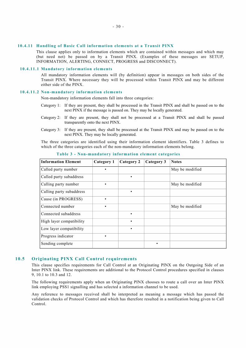
- 30 -
10.4.11 Handling of Basic Cal l information elements at a Transit PINX This clause applies only to information elements which are contained within messages and which may (but need not) be passed on by a Transit PINX. (Examples of these messages are SETUP, INFORMATION, ALERTING, CONNECT, PROGRESS and DISCONNECT).
10.4.11.1 Mandatory information e lements All mandatory information elements will (by definition) appear in messages on both sides of the Transit PINX. Where necessary they will be processed within Transit PINX and may be different either side of the PINX.
10.4.11.2 Non-mandatory information e lements Non-mandatory information elements fall into three categories:
Category 1: If they are present, they shall be processed in the Transit PINX and shall be passed on to the next PINX if the message is passed on. They may be locally generated.
Category 2: If they are present, they shall not be processed at a Transit PINX and shall be passed transparently onto the next PINX.
Category 3: If they are present, they shall be processed at the Transit PINX and may be passed on to the next PINX. They may be locally generated.
The three categories are identified using their information element identifiers. Table 3 defines to which of the three categories each of the non-mandatory information elements belong.
Table 3 - Non-mandatory information element categories
Information Element Category 1 Category 2 Category 3 Notes
Called party number • May be modified
Called party subaddress •
Calling party number • May be modified
Calling party subaddress •
Cause (in PROGRESS) •
Connected number • May be modified
Connected subaddress •
High layer compatibility •
Low layer compatibility •
Progress indicator •
Sending complete •
10.5 Originating PINX Call Control requirements This clause specifies requirements for Call Control at an Originating PINX on the Outgoing Side of an Inter PINX link. These requirements are additional to the Protocol Control procedures specified in clauses 9, 10.1 to 10.3 and 12.
The following requirements apply when an Originating PINX chooses to route a call over an Inter PINX link employing PSS1 signalling and has selected a information channel to be used.
Any reference to messages received shall be interpreted as meaning a message which has passed the validation checks of Protocol Control and which has therefore resulted in a notification being given to Call Control.
- 31 -
10.5.1 Transmiss ion of the SETUP message The Originating PINX shall transmit a SETUP message. The SETUP message shall include optional information elements according to the following rules.
a) Sending complete. The Originating PINX may optionally send this information element if it can determine that the number in the Called party number information element is complete or if this has been indicated by the calling terminal.
b) Progress indicator. The Originating PINX shall pass on, by means of the Progress indicator information element, progress information received from the calling user.
The Originating PINX may insert a Progress indicator information element containing CCITT progress description 3 “Origination address is non-ISDN” if neither the calling terminal nor the combination of the PINX and the calling terminal has the functionality of an ISDN terminal.
c) Calling party number. The Originating PINX shall include the calling party number information element identifying the calling user. The presentation indicator shall have the value “presentation restricted” if supplementary service Calling/Connected Line Identification Restriction (see ECMA-148) has been invoked at the calling user. Otherwise the presentation indicator, if present, shall have the value "presentation allowed".
d) Calling party subaddress. The Originating PINX shall include the calling party subaddress information element if a calling party subaddress is available.
e) Called party subaddress. The Originating PINX shall include the called party subaddress information element if a called party subaddress is available.
f) Low layer compatibility. The Originating PINX shall include the low layer compatibility information element if low layer compatibility information is available.
g) High layer compatibility. The Originating PINX shall include the high layer compatibility information element if high layer compatibility information is available.
10.5.2 Agreement of the information channel On receipt of a SETUP ACKNOWLEDGE, CALL PROCEEDING, ALERTING or CONNECT message agreeing the channel(s) proposed in the SETUP message or suggesting one or more alternative channels which the Originating PINX finds acceptable, the Originating PINX may optionally connect the information channel(s) in the forward direction, in the backward direction or in both directions.
NOTE 1 It is recommended that information channel(s) are connected in both directions at this stage, particularly for services involving the conveyance of speech information. Leaving the information channel(s) unconnected until a later stage, particularly in the backward direction, may lead to the “clipping” of speech. However, there may be reasons for delaying connection, particularly in the forward direction, e.g., to avoid the onward transmission of in-band signalling information from the user's access.
NOTE 2 If the received message is an ALERTING or CONNECT message, 10.5.4 or 10.5.5 shall apply, respectively.
10.5.3 Receipt of Progress indicators Information received in a Progress indicator information element in a PROGRESS message, an ALERTING message or a CONNECT message, shall be conveyed to the calling user - dependent on the ability of the calling user's equipment to receive such information.
On receipt of a Progress indicator information element with CCITT progress description number 8 “in-band information or appropriate pattern now available” or CCITT progress description number 1 “call is not end-to-end ISDN, further call progress information may be available in-band” the Originating PINX shall connect the information channel(s) in the backward direction if it has not already done so.
10.5.4 Receipt of ALERTING message On receipt of an ALERTING message, an indication of alerting may be given to the calling user.
- 32 -
Through connection may occur at this point. If the received message contains a Progress indicator information element with CCITT progress description number 8 “in-band information or appropriate pattern now available” or CCITT progress description number 1 “call is not end-to-end ISDN, further call progress information may be available in-band” the Originating PINX shall connect the information channel(s) in the backward direction if it has not already done so.
10.5.5 Receipt of CONNECT message On receipt of a CONNECT message, the Originating PINX shall connect the information channel(s) in both directions, if it has not already done so, and shall indicate connection to the calling user.
If the CONNECT message contains a Connected number information element and/or a Connected subaddress information element, this information may be used for purposes such as the provision of the Connected Line Identification Presentation supplementary service to the calling user.
If the CONNECT message contains a Low Layer Compatibility information element, the information may be passed on to the calling user.
10.5 .6 Cal l c learing init iated by the Originat ing PINX The Originating PINX may initiate clearing on the inter-PINX link employing PSS1 signalling if a clear request is received from the calling user or if a failure condition occurs. Clearing is initiated by informing Protocol Control and supplying a Cause.
Alternatively, for services for which an in-band tone or announcement is appropriate, the Originating PINX may connect an in-band tone or announcement to the outgoing information channel(s) and may optionally transmit a PROGRESS message containing a Progress indicator information element with CCITT progress description 8 “in-band information or appropriate pattern now available” and an appropriate Cause. If an indication of clearing has not been received from Protocol Control by the time the tone or announcement is complete or has been applied for sufficient time, the Originating PINX shall instruct Protocol Control to initiate clearing.
NOTE It is recommended that an in-band tone or announcement be provided by the Originating PINX only if it conveys call failure information which is not conveyable by PSS1.
10.5.7 Receipt of an indicat ion of cal l c learing On receipt of an indication of call clearing from Protocol Control, the Originating PINX shall either indicate to the calling user that the call has cleared or take some other implementation dependent action.
10.6 Terminating PINX Call Control requirements This clause specifies requirements for Call Control at a Terminating PINX on the Incoming Side of an inter-PINX link. These requirements are additional to the Protocol Control procedures specified in clauses 9, 10.1 to 10.3 and 12.
NOTE If enbloc signalling only is used between two adjacent PINXs, overlap receiving procedures need not be tested.
The following requirements apply when a PINX receives a SETUP message, possibly followed by one or more INFORMATION messages conveying additional Called party number information, and determines that the destination is a user on that PINX. The PINX therefore becomes a Terminating PINX.
Any reference to messages received shall be interpreted as meaning a message which has passed the validation checks of Protocol Control and which has therefore resulted in a notification being given to Call Control.
10.6.1 Receipt of the SETUP message Optional information elements in the received SETUP message shall be used as follows.
a) Progress indicator. If the SETUP message contains a Progress indicator information element, the information therein may optionally be passed on to the called user.
b) Low layer compatibility, high layer compatibility and called party subaddress. If the SETUP message contains one or more of these information elements, and if the user is connected by means of an

- 33 -
ISDN interface at the S reference point, the information element(s) shall be conveyed to the called user and the user may act upon the information therein. If the user is connected by means of a non-ISDN interface, conveyance of the information to the user depends on the user's ability to receive it.
c) Calling party number and calling party subaddress. Information in the calling party number information element, and also in the optional calling party subaddress information element, may be used for purposes such as the provision of the Calling Line Identification Presentation supplementary service to the called user.
10.6 .2 Transmiss ion of ALERTING message The Terminating PINX shall transmit an ALERTING message when it is aware that the called user is being alerted.
For services which require an in-band tone or announcement to be supplied to the calling user during the period of alerting, the Terminating PINX is responsible for connecting the appropriate tone or announcement to the information channel(s) in the backwards direction. If a tone or announcement is connected, the Terminating PINX shall include a Progress indicator information element with CCITT progress description number 8 “in-band information or appropriate pattern now available” in the ALERTING message.
10.6.3 Transmiss ion of Progress indicators The Terminating PINX shall pass on, by means of the Progress indicator information element, progress information received from the called user, either before or after the transmission of an ALERTING message.
The Terminating PINX may send a Progress indicator information element containing CCITT progress description number 2 “Destination address is non-ISDN” if neither the called terminal nor the combination of the PINX and the called terminal has the functionality of an ISDN terminal.
A Progress indicator information element shall be transmitted in an ALERTING message or a CONNECT message if an ALERTING message or a CONNECT message is being sent at the time. Otherwise it shall be transmitted in a PROGRESS message.
10.6 .4 Transmiss ion of CONNECT message When the Terminating PINX is aware that the called user has accepted the call, it shall connect the information channel(s) in both directions and send a CONNECT message. Any in-band tone or announcement shall be disconnected.
The Terminating PINX shall include in the CONNECT message the Connected number information element. The presentation indicator shall have the value “presentation restricted” if supplementary service Calling/Connected Line Identification Restriction (see ECMA-148) has been invoked at the called user. Otherwise the presentation indicator, if present, shall have the value "presentation allowed".
The Terminating PINX shall include in the CONNECT message the Connected subaddress information element if a Connected subaddress is available.
The Terminating PINX may include in the CONNECT message the low layer compatibility information element if low layer compatibility information has been supplied by the called terminal.
10.6.5 Cal l c learing init iated by the Terminating PINX The Terminating PINX may initiate clearing on the inter-PINX link employing PSS1 signalling if it is not able to proceed with call establishment, if a failure condition occurs after the call has been established, or if a clear request is received from the called user. Clearing is initiated by informing Protocol Control and supplying a Cause.
Alternatively, for services for which an in-band tone or announcement is appropriate, the Terminating PINX may connect an in-band tone or announcement to the incoming information channel(s) and transmit a PROGRESS message containing a Progress indicator information element with CCITT progress description 8 “in-band information or appropriate pattern now available” and an appropriate Cause. If an indication of clearing has not been received from Protocol Control by the time the tone or announcement is complete or has been applied for sufficient time, the Terminating PINX shall instruct
- 34 -
Protocol Control to initiate clearing. The sending of the PROGRESS message is optional in the Active state but mandatory in other states.
NOTE It is recommended that an in-band tone or announcement be provided by the Terminating PINX only if it conveys call rejection or failure information which is not conveyable by PSS1.
10.6.6 Receipt of an indicat ion of cal l c learing On receipt of an indication of call clearing from Protocol Control, the Terminating PINX shall either indicate to the called user that the call has cleared or take some other implementation dependent action.
10.7 Incoming Gateway PINX Call Control requirements This clause specifies requirements for Call Control at an Incoming Gateway PINX on the Outgoing Side of an inter-PINX link. These requirements are additional to the Protocol Control procedures specified in clauses 9, 10.1 to 10.3 and 12.
The following requirements apply when a call entering the PISN is routed, by the Incoming Gateway PINX, over an inter-PINX link employing PSS1 signalling, an information channel on that link having been selected.
Any reference to messages received shall be interpreted as meaning a message which has passed the validation checks of Protocol Control and which has therefore resulted in a notification being given to Call Control.
10.7.1 Transmiss ion of the SETUP message The Incoming Gateway PINX shall transmit a SETUP message. The SETUP message shall include optional information elements according to the following rules.
a) Sending complete. The Incoming Gateway PINX may optionally send this information element if it can determine that the number in the Called party number information element is complete or if this has been indicated by the other network.
b) Progress indicator. The inclusion of a Progress indicator information element by the Incoming Gateway PINX shall be in accordance with clause 10.7.2.
c) Calling party number. If the other network has supplied a calling party number with or without an indication that presentation is restricted or a restriction indication only, the Incoming Gateway PINX shall include this information in the SETUP message within the calling party number information element. Otherwise the calling party number information element shall either contain the presentation indicator value “number not available due to interworking” or be omitted.
d) Calling party subaddress. If the other network is a public ISDN and supplies a calling party subaddress information element, the Incoming Gateway PINX shall pass on the information element unchanged in the SETUP message. The Incoming Gateway PINX may also include a calling party subaddress information element in the SETUP message if calling party subaddress information has been supplied by a non-ISDN.
e) Called party subaddress. If the other network is a public ISDN and supplies a called party subaddress information element, the Incoming Gateway PINX shall pass on the information element unchanged in the SETUP message. The Incoming Gateway PINX may also include a called party subaddress information element in the SETUP message if called party subaddress information has been supplied by a non-ISDN.
f) Low layer compatibility. If the other network is a public ISDN and supplies a low layer compatibility information element, the Incoming Gateway PINX shall pass on the information element unchanged in the SETUP message. The Incoming Gateway PINX may also include a low layer compatibility information element in the SETUP message if low layer compatibility information has been supplied by a non-ISDN.
g) High layer compatibility. If the other network is a public ISDN and supplies a high layer compatibility information element, the Incoming Gateway PINX shall pass on the information element unchanged in the SETUP message. The Incoming Gateway PINX may also include a high
- 35 -
layer compatibility information element in the SETUP message if high layer compatibility information has been supplied by a non-ISDN.
10.7.2 Interworking indicat ions in the SETUP Message The inclusion of the Progress indicator information element in the SETUP message shall be as specified below. If none of the specified conditions apply, no Progress indicator information element shall be included.
10.7.2 .1 Interworking indicat ions received from a public ISDN If the call has arrived from a public ISDN and a Progress indicator information element containing one of the following CCITT progress descriptions has been received from the public ISDN, that information element shall be passed on:
– 1 “call is not end-to-end ISDN, further call progress information may be available in-band”
– 3 “origination address is non-ISDN”
10.7 .2 .2 Interworking with a non-ISDN If the call has entered the PISN from a network (public or private) which is not ISDN, a Progress indicator information element may be sent containing CCITT progress description number 1 “call is not end-to-end ISDN, further call progress information may be available in-band”.
NOTE Terminals in the PISN that support only the "Speech" bearer capability can only accept calls indicating either "Speech" bearer capability or "3.1kHz audio" bearer capability together with progress indicator containing CCITT progress description number 1 "call is not end to end ISDN, further call progress information may be available in-band". It is recommended that this is taken into account when providing an incoming gateway function to a non-ISDN network supporting speech based telephony.
10.7.3 Agreement of the information channel On receipt of a SETUP ACKNOWLEDGE, CALL PROCEEDING, ALERTING or CONNECT message agreeing the channel(s) proposed in the SETUP message or suggesting one or more alternative channels which the Incoming Gateway PINX finds acceptable, the Incoming Gateway PINX may optionally connect the information channel(s) in the forward direction, in the backward direction or in both directions.
NOTE It is recommended that the information channel(s) are connected in both directions at this stage, particularly for services involving the conveyance of speech information. Leaving the information channel(s) unconnected until a later stage, particularly in the backward direction, may lead to the “clipping” of speech. However, there may be reasons for delaying connection, particularly in the forward direction, e.g., to avoid the onward transmission of in-band signalling information from the other network.
10.7.4 Receipt of Progress indicators Information received in a Progress indicator information element in a PROGRESS message, an ALERTING message, or a CONNECT message shall be passed on to the other network if the signalling system permits and if relevant.
On receipt of a Progress indicator information element with CCITT progress description number 8 “in-band information or appropriate pattern now available” or CCITT progress description number 1 “call is not end-to-end ISDN, further call progress information may be available in-band” the Incoming Gateway PINX shall connect the information channel(s) in the backward direction if it has not already done so.
10.7.5 Receipt of ALERTING message On receipt of an ALERTING message, an indication of alerting may be given to the other network if the signalling system permits.
If the ALERTING message contains a Progress indicator information element with CCITT progress description number 8 “in-band information or appropriate pattern now available” or CCITT progress description number 1 “call is not end-to-end ISDN, further call progress information may be available
- 36 -
in-band” the Incoming Gateway PINX shall connect the information channel(s) in the backward direction if it has not already done so.
10.7.6 Receipt of CONNECT message On receipt of a CONNECT message, the Incoming Gateway PINX shall connect the information channel(s) in both directions, if it has not already done so, and shall indicate connection to the other network if the signalling system permits.
If the CONNECT message contains a low layer compatibility information element, the information element shall be conveyed unchanged to the other network if that network is a public ISDN. Where the other network is non-ISDN, low layer compatibility information may be conveyed to the other network if the signalling system permits.
If the CONNECT message contains a Connected number information element, conveyance of the information therein to the other network depends on the capability of the signalling system and whether the Connected number has significance in the other network. Translation of a number into the numbering plan of the other network may be performed in order to yield a number which has significance in the other network.
If the CONNECT message contains a Connected subaddress information element, the information element shall be conveyed unchanged to the other network if that network is a public ISDN. Where the other network is non-ISDN, Connected subaddress information may be conveyed to the other network if the signalling system permits.
If the received Connected number information element has the presentation indicator value “presentation restricted”, presentation of the number to the other network is outside the scope of this Standard, but will depend on such factors as the other network’s commitment to honour the restriction.
10.7 .7 Cal l c learing init iated by the Incoming Gateway PINX The Incoming Gateway PINX may initiate clearing on the inter-PINX link employing PSS1 signalling if a clear request is received from other network or if a failure condition occurs. Clearing is initiated by informing Protocol Control and supplying a Cause.
Alternatively, for services for which an in-band tone or announcement is appropriate, the Incoming Gateway PINX may connect an in-band tone or announcement to the outgoing information channel(s) and may optionally transmit a PROGRESS message containing a Progress indicator information element with CCITT progress description number 8 “in-band information or appropriate pattern now available” and an appropriate Cause. In cases where the other network indicates that it is providing an in-band tone or announcement in preparation for clearing, the Incoming Gateway PINX may transmit a PROGRESS message containing a Progress indicator information element with CCITT progress description number 8 “in-band information or appropriate pattern now available”.
In all the above cases:
– if an indication of clearing has not been received from Protocol Control by the time the tone or announcement is complete or has been applied for sufficient time, the Incoming Gateway PINX shall instruct Protocol Control to initiate clearing.
– the sending of the PROGRESS message is optional in the Active state, but mandatory in other call states.
NOTE It is recommended that an in-band tone or announcement be provided by the Incoming Gateway PINX only if it conveys call failure information which is not conveyable by PSS1.
10.7.8 Receipt of an indicat ion of cal l c learing On receipt of an indication of call clearing from Protocol Control, the Incoming Gateway PINX shall either indicate to the other network that the call has cleared or take some other implementation dependent action.
- 37 -
10.8 Outgoing Gateway PINX Call Control requirements This clause specifies requirements for Call Control at an Outgoing Gateway PINX on the Incoming Side of an inter-PINX link. These requirements are additional to the Protocol Control procedures specified in clauses 9, 10.1 to 10.3 and 12.
The following requirements apply when a PINX receives a SETUP message, possibly followed by one or more INFORMATION messages conveying additional Called party number information, and determines that the call is to be routed directly (not via any further PINX) to another network. The PINX therefore becomes an Outgoing Gateway PINX.
Any reference to messages received shall be interpreted as meaning a message which has passed the validation checks of Protocol Control and which has therefore resulted in a notification being given to Call Control.
10.8.1 Receipt of the SETUP message Information elements in the received SETUP message shall be used as follows.
a) Progress indicator. If the SETUP message contains a Progress indicator information element, the information therein shall be passed on to the other network if the signalling system permits and if relevant.
b) Low layer compatibility, high layer compatibility, called party subaddress and calling party subaddress. If the SETUP message contains one or more of these information elements, the information element(s) shall be conveyed unchanged to the other network if that network is a public ISDN. Where the other network is non-ISDN, information from these elements may be conveyed to the other network if the signalling system permits. However, the calling party subaddress information element shall not be sent to the network if the presentation indicator in the received calling party number information element has the value “presentation restricted”.
c) Calling party number. If the SETUP message contains a calling party number information element, conveyance of the information therein to the other network depends on the capability of the signalling system and whether the calling party number has significance in the other network. Translation of a number into the numbering plan of the other network may be performed in order to yield a number which has significance in the other network. If the received calling party number information element has the presentation indicator value "presentation restricted", presentation of the number to the other network is outside the scope of this Standard, but will depend on such factors as the other network's commitment to honour the restriction.
10.8 .2 Connect ion of the information channel The Outgoing Gateway PINX may optionally connect the information channel(s) in the forward direction, in the backward direction or in both directions as soon as the channel(s) to the other network have been agreed.
NOTE It is recommended that the information channel(s) are connected in both directions at this stage, particularly for services involving the conveyance of speech information. Leaving the information channel(s) unconnected until a later stage, particularly in the backward direction, may lead to the “clipping” of speech or the loss of in-band tones or announcements. However, there may be reasons for delaying connection, particularly in the forward direction, e.g., while transmitting in-band signalling information.
10.8.3 Transmiss ion of interworking indicat ions The Outgoing Gateway PINX shall transmit Progress indicator information elements as specified below. A Progress indicator information element shall be transmitted in a PROGRESS message, an ALERTING message or a CONNECT message as soon as the information becomes available, subject to a SETUP ACKNOWLEDGE or CALL PROCEEDING message having already been sent. A PROGRESS message shall be used unless an ALERTING or CONNECT message is to be sent at the time. All appropriate interworking indications shall be transmitted by the Outgoing Gateway PINX.
- 38 -
10.8.3 .1 Interworking indicat ions received from a public ISDN If the call has entered a public ISDN and a Progress indicator information element containing one of the following CCITT progress descriptions has been received from the public ISDN, that information element shall be passed on:
– 1 “call is not end-to-end ISDN, further call progress information may be available in-band”
– 2 “destination address is non-ISDN”
– 4 “call has returned to the ISDN”
– 8 “in-band information or appropriate pattern now available”
In the case of progress description number 1 “call is not end to end ISDN, further information may be available in band” and number 8 “in band information or appropriate pattern now available”, the Outgoing Gateway PINX shall connect the information channel in the backward direction if it has not already done so.
10.8 .3 .2 Interworking with a non-ISDN If the call is to enter a network (public or private) which is not ISDN, a progress indicator information element may be sent containing CCITT progress description number 1 “call is not end-to-end ISDN, further call progress information may be available in-band”. If this Progress indicator information element is sent, the Outgoing Gateway PINX shall connect the information channel in the backward direction if it has not already done so.
10.8 .4 Transmiss ion of ALERTING message The Outgoing Gateway PINX shall transmit an ALERTING message when it receives an indication from the other network that the called user is being alerted. Some other networks may be unable to indicate alerting.
For services which require an in-band tone or announcement to be supplied to the calling user during the period of alerting, the Outgoing Gateway PINX is responsible for connecting the appropriate tone or announcement to the information channel(s) in the backwards direction, unless an appropriate tone or announcement is being provided by the other network. If a tone or announcement is being provided either by the Outgoing Gateway PINX or by the other network, the Outgoing Gateway PINX shall include a Progress indicator information element with CCITT progress description 8 “in-band information or appropriate pattern now available” in the ALERTING message.
10.8 .5 Transmiss ion of CONNECT message When the Outgoing Gateway PINX receives an answer signal from the other network, it shall connect the information channel(s) in both directions, if it has not already done so, and send a CONNECT message.
If the other network is not always able to supply an indication of call acceptance, the Outgoing Gateway PINX shall connect the information channel(s) in both directions and send a CONNECT message when a suitable time interval has elapsed following the sending of call information to the other network. The time interval chosen should take account of the shortest likely time to indicate the call acceptance. If, subsequent to sending a CONNECT message, an indication of call acceptance is received from the other network, the Outgoing Gateway PINX shall not send a second CONNECT message.
If the other network has supplied a Connected number with or without an indication that presentation is restricted or a restriction indication only, the Outgoing Gateway PINX shall include this information in the CONNECT message within the Connected number information element. Otherwise the Connected number information element shall either contain the presentation indicator value “number not available due to interworking” or be omitted.
If the other network is a public ISDN and supplies a Connected subaddress information element, the Outgoing Gateway PINX shall pass the information element on unchanged in the CONNECT message. The Outgoing Gateway PINX may also include a Connected subaddress information element in the CONNECT message if Connected subaddress information has been supplied by a non-ISDN.
If the other network is a public ISDN and supplies a low layer compatibility information element, the Outgoing Gateway PINX may pass the information element on unchanged in the CONNECT message.
- 39 -
The Outgoing Gateway PINX may also include a low layer compatibility information element in the CONNECT message if low layer compatibility information has been supplied by a non-ISDN.
10.8 .6 Call c learing init iated by the Outgoing Gateway PINX The Outgoing Gateway PINX may initiate clearing on the inter-PINX link employing PSS1 signalling if it is not able to proceed with call establishment, if a failure condition occurs after the call has been established, or if a clear request is received from the other network. Clearing is initiated by informing Protocol Control and supplying a Cause.
Alternatively, for services for which an in-band tone or announcement is appropriate, the Outgoing Gateway PINX may connect an in-band tone or announcement to the incoming information channel(s) and transmit a PROGRESS message containing a Progress indicator information element with CCITT progress description 8 “in-band information or appropriate pattern now available” and an appropriate Cause. A PROGRESS message containing a Progress indicator information element with CCITT progress description number 8 “in-band information or appropriate pattern now available” may also be sent in cases where the other network indicates that it is providing an in-band tone or announcement in preparation for clearing.
In all of the above cases:
– If an indication of clearing has not been received from Protocol Control by the time the tone or announcement is complete or has been applied for sufficient time, the Outgoing Gateway PINX shall instruct Protocol Control to initiate clearing.
– The sending of the PROGRESS message is optional in the Active state but mandatory in other states.
NOTE It is recommended that an in-band tone or announcement be provided by the Outgoing Gateway PINX only if it conveys call rejection or failure information which is not conveyable by PSS1.
10.8.7 Receipt of an indicat ion of cal l c learing On receipt of an indication of call clearing from Protocol Control, the Outgoing Gateway PINX shall either indicate to the other network that the call has cleared or take some other implementation dependent action.
11 Procedures for layer management 11.1 Restart procedures
The restart procedure may be used to return a single channel, or all channels associated with the signalling channel, to the idle condition and calls associated with these channels to the Null state. The procedure may be invoked when the adjacent PINX does not respond to Call control messages, a failure has occurred or a maintenance action has taken place or for some other (unspecified) reason (e.g. following a SCM failure; or following the second expiry of timer T308 due to the absence of response to a clearing message).
11.1.1 Sending RESTART A RESTART message may be sent by either side in order to return an indicated channel, multiple indicated channels or all channels associated with the signalling channel to the idle state. The Restart indicator information element shall be present in the RESTART message to indicate whether one or more indicated channels or all channels are to be restarted. If the Restart indicator is coded as “indicated channel”, then the Channel identification information element shall be present to indicate which channel(s) are to be returned to the idle condition. In the case where multiple channels (but not all channels associated with the signalling channel) are to be restarted, the Channel identification information element shall be present to indicate the channels to be restarted. If the Restart indicator information element is coded “all channels”, then the Channel identification information element shall not be included.
Upon transmitting the RESTART message the sending entity shall enter the Restart Request state, start timer T316, and wait for a RESTART ACKNOWLEDGE message. No further RESTART messages shall be sent until a RESTART ACKNOWLEDGE message is received or timer T316 expires.
- 40 -
Receipt of a RESTART ACKNOWLEDGE message shall stop timer T316, free the channels and Call reference values (associated with the channels identified by the RESTART message) for reuse, and cause the receiving entity to enter the Null state.
If a RESTART ACKNOWLEDGE message is not received prior to expiry of timer T316 one or more subsequent RESTART messages may be sent until a RESTART ACKNOWLEDGE message is returned - the limit of the number of times RESTART may be sent is implementation dependent.
Meanwhile, no calls shall be placed or accepted on the channels identified in the RESTART message by the originator of the message. When the limit for the number of restarts is reached, the originator shall make no further restart attempts. An indication shall be provided to the appropriate maintenance entity. The channels identified shall be considered to be in an out-of-service condition until maintenance action has been taken.
The RESTART and RESTART ACKNOWLEDGE messages shall contain the Global call reference value with which the Restart Request state is associated.
11.1.2 Receipt of RESTART Upon receiving a RESTART message the recipient shall enter the Restart state associated with the Global call reference. It shall then initiate the appropriate internal actions to return the specified channels to the idle condition and call reference(s) associated with those channels to the Null state. Upon completion of internal clearing a RESTART ACKNOWLEDGE message shall be transmitted to the originator, and the transmitting entity shall enter the Null state.
Even if all Call references are in the Null state and all channels are in the idle condition, the receiving entity shall transmit a RESTART ACKNOWLEDGE message to the originator on receiving a RESTART message.
If the Restart indicator information element is coded as “indicated channel” and the Channel identification information element is not included, the procedures of 9.2.6.1 shall apply.
11.1 .3 Restart col l is ion Restart collision occurs at Inter-PINX link when both sides of the inter-PINX link simultaneously transmit a RESTART message. The Call reference flag of the Global call reference applies to the restart procedures. In the case when both sides on an inter-PINX link initiate simultaneous restart requests, they shall be handled independently. In the case when the same channel(s) are specified, they shall not be considered for re-use until all the relevant restart procedures are completed.
12 Protocol timers The protocol timers are defined in table 4. All timer values given in this table have a tolerance of 10%.
Legend to table 4, columns 7 and 8:
– M The timer is mandatory
– O The timer is optional
– M(I) The timer is mandatory if the associated procedures are implemented.
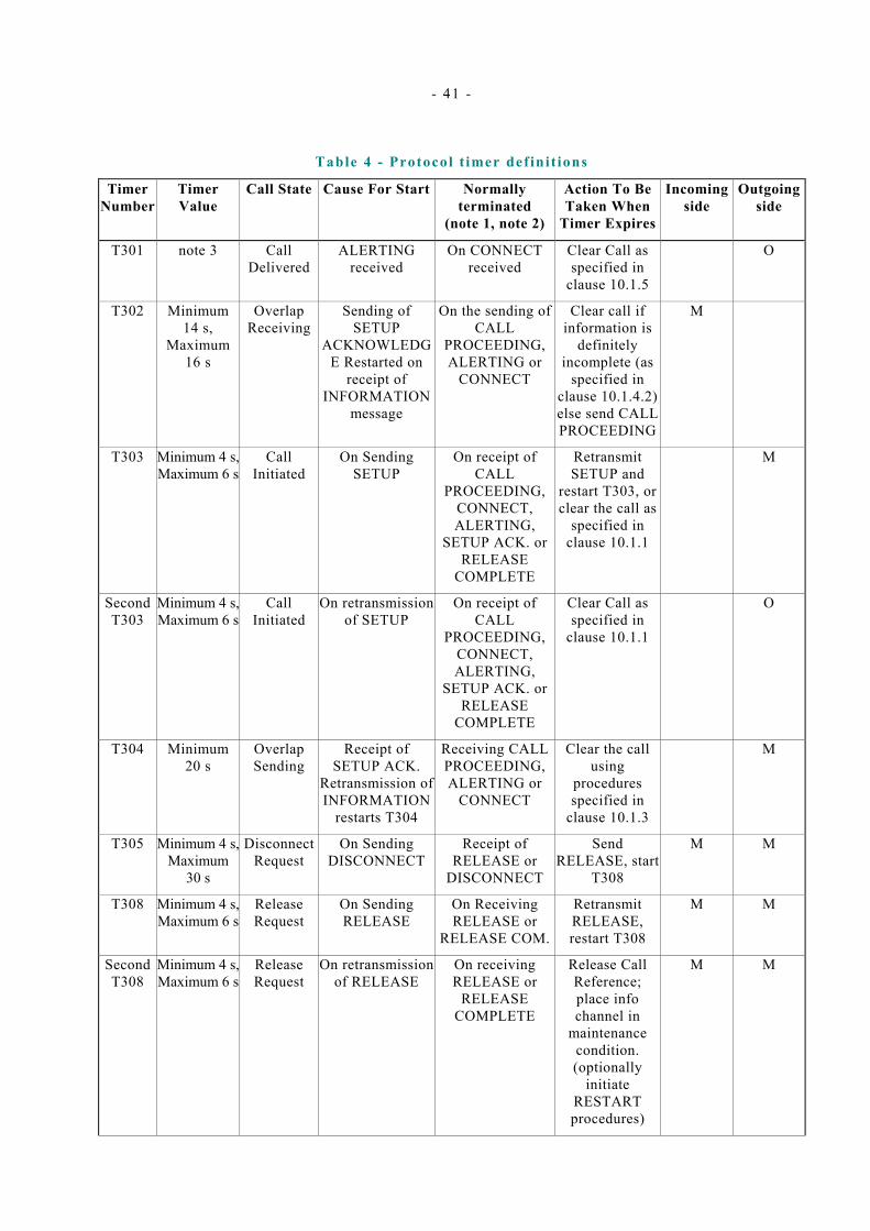
- 41 -
Table 4 - Protocol t imer def init ions
Timer Number
Timer Value
Call State Cause For Start Normally terminated
(note 1, note 2)
Action To Be Taken When
Timer Expires
Incoming side
Outgoing side
T301 note 3 Call Delivered
ALERTING received
On CONNECT received
Clear Call as specified in
clause 10.1.5
O
T302 Minimum 14 s,
Maximum 16 s
Overlap Receiving
Sending of SETUP
ACKNOWLEDGE Restarted on
receipt of INFORMATION
message
On the sending of CALL
PROCEEDING, ALERTING or
CONNECT
Clear call if information is
definitely incomplete (as
specified in clause 10.1.4.2) else send CALL PROCEEDING
M
T303 Minimum 4 s, Maximum 6 s
Call Initiated
On Sending SETUP
On receipt of CALL
PROCEEDING, CONNECT, ALERTING,
SETUP ACK. or RELEASE
COMPLETE
Retransmit SETUP and
restart T303, or clear the call as
specified in clause 10.1.1
M
Second T303
Minimum 4 s, Maximum 6 s
Call Initiated
On retransmission of SETUP
On receipt of CALL
PROCEEDING, CONNECT, ALERTING,
SETUP ACK. or RELEASE
COMPLETE
Clear Call as specified in
clause 10.1.1
O
T304 Minimum 20 s
Overlap Sending
Receipt of SETUP ACK.
Retransmission of INFORMATION
restarts T304
Receiving CALL PROCEEDING, ALERTING or
CONNECT
Clear the call using
procedures specified in
clause 10.1.3
M
T305 Minimum 4 s, Maximum
30 s
Disconnect Request
On Sending DISCONNECT
Receipt of RELEASE or
DISCONNECT
Send RELEASE, start
T308
M M
T308 Minimum 4 s, Maximum 6 s
Release Request
On Sending RELEASE
On Receiving RELEASE or
RELEASE COM.
Retransmit RELEASE, restart T308
M M
Second T308
Minimum 4 s, Maximum 6 s
Release Request
On retransmission of RELEASE
On receiving RELEASE or
RELEASE COMPLETE
Release Call Reference; place info channel in
maintenance condition. (optionally
initiate RESTART procedures)
M M
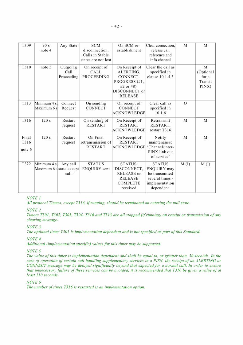
- 42 -
T309 90 s note 4
Any State SCM disconnection. Calls in Stable
states are not lost
On SCM re-establishment
Clear connection, release call
reference and info channel
M M
T310 note 5 Outgoing Call
Proceeding
On receipt of CALL
PROCEEDING
On Receipt of ALERTING, CONNECT,
PROGRESS (#1, #2 or #8),
DISCONNECT or RELEASE
Clear the call as specified in
clause 10.1.4.3
M (Optional
for a Transit PINX)
T313 Minimum 4 s, Maximum 6 s
Connect Request
On sending CONNECT
On receipt of CONNECT
ACKNOWLEDGE
Clear call as specified in
10.1.6
O
T316 120 s Restart request
On sending of RESTART
On Receipt of RESTART
ACKNOWLEDGE
Retransmit RESTART, restart T316
M M
Final T316
note 6
120 s Restart request
On Final retransmission of
RESTART
On Receipt of RESTART
ACKNOWLEDGE
Notify maintenance:
‘Channel/inter-PINX link out
of service’
M M
T322 Minimum 4 s, Maximum 6 s
Any call state except
null.
STATUS ENQUIRY sent
STATUS, DISCONNECT,
RELEASE or RELEASE
COMPLETE received
STATUS ENQUIRY may be transmitted several times - implementation
dependant.
M (I) M (I)
NOTE 1 All protocol Timers, except T316, if running, should be terminated on entering the null state.
NOTE 2 Timers T301, T302, T303, T304, T310 and T313 are all stopped (if running) on receipt or transmission of any clearing message.
NOTE 3 The optional timer T301 is implementation dependent and is not specified as part of this Standard.
NOTE 4 Additional (implementation specific) values for this timer may be supported.
NOTE 5 The value of this timer is implementation dependent and shall be equal to, or greater than, 30 seconds. In the case of operation of certain call handling supplementary services in a PISN, the receipt of an ALERTING or CONNECT message may be delayed significantly beyond that expected for a normal call. In order to ensure that unnecessary failure of these services can be avoided, it is recommended that T310 be given a value of at least 110 seconds.
NOTE 6 The number of times T316 is restarted is an implementation option.

- 43 -
13 Functional definition of messages This clause provides an overview of the structure of messages used in this Standard and defines the function and information contents (i.e. semantics) of each message.
Whenever a message is sent, according to the procedures of clauses 9, 10 and 11, it shall contain the mandatory information elements, and optionally any combination of the optional information elements, specified in this clause for that message.
Each definition includes:
a) A brief description of the message direction and use.
b) A table listing the information elements of codeset 0 in the order of their appearance in the message (same relative order for all message types).
c) Indications for each information element in the table, specifying:
• the clause of this Standard describing the information element;
• whether inclusion is mandatory (“M”) or optional (“O”);
• the length (or length range) of the information element, where “*” denotes an undefined maximum length which may be network or service dependent. Note that certain optional information elements may be present in the message, but empty (length = 2 octets), but this case is not considered in the tables.
d) Further explanatory notes, as necessary.
Other messages and information elements may be required for the support of supplementary services and additional network features; these will be defined in other standards.
Unless otherwise qualified by an individual note, information elements marked as optional in the definition of a message should be included whenever the sender is able to provide the information (i.e. the information is available at the sending side of a link), if it has not been sent before.
13.1 Messages for general procedures 13.1 .1 STATUS
This message is sent by either side in response to a STATUS ENQUIRY message or at any time during a call to report certain error conditions.
Table 5 - STATUS message content
Message Type: STATUS Direction: both
Information Element Reference Type Length Protocol discriminator 14.2 M 1 Call reference 14.3 M (note 1) 3 Message type 14.4 M 1 Cause 14.5 M 4-32 Call state 14.5 M 3
NOTE 1 This message may be sent with the global call reference.
13.1 .2 STATUS ENQUIRY This message may be sent by either side at any time to solicit a STATUS message from the peer signalling entity.
Table 6 - STATUS ENQUIRY message content
Message Type: STATUS ENQUIRY Direction: both
Information Element Reference Type Length Protocol discriminator 14.2 M 1 Call reference 14.3 M 3 Message type 14.4 M 1
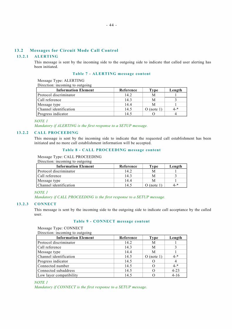
- 44 -
13.2 Messages for Circuit Mode Call Control 13.2 .1 ALERTING
This message is sent by the incoming side to the outgoing side to indicate that called user alerting has been initiated.
Table 7 - ALERTING message content
Message Type: ALERTING Direction: incoming to outgoing
Information Element Reference Type Length Protocol discriminator 14.2 M 1 Call reference 14.3 M 3 Message type 14.4 M 1 Channel identification 14.5 O (note 1) 4-* Progress indicator 14.5 O 4
NOTE 1 Mandatory if ALERTING is the first response to a SETUP message.
13.2 .2 CALL PROCEEDING This message is sent by the incoming side to indicate that the requested call establishment has been initiated and no more call establishment information will be accepted.
Table 8 - CALL PROCEEDING message content
Message Type: CALL PROCEEDING Direction: incoming to outgoing
Information Element Reference Type Length Protocol discriminator 14.2 M 1 Call reference 14.3 M 3 Message type 14.4 M 1 Channel identification 14.5 O (note 1) 4-*
NOTE 1 Mandatory if CALL PROCEEDING is the first response to a SETUP message.
13.2 .3 CONNECT This message is sent by the incoming side to the outgoing side to indicate call acceptance by the called user.
Table 9 - CONNECT message content
Message Type: CONNECT Direction: incoming to outgoing
Information Element Reference Type Length Protocol discriminator 14.2 M 1 Call reference 14.3 M 3 Message type 14.4 M 1 Channel identification 14.5 O (note 1) 4-* Progress indicator 14.5 O 4 Connected number 14.5 O 4-* Connected subaddress 14.5 O 4-23 Low layer compatibility 14.5 O 4-16
NOTE 1 Mandatory if CONNECT is the first response to a SETUP message.
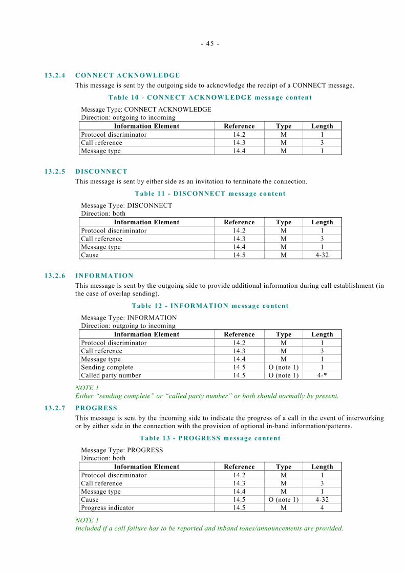
- 45 -
13.2.4 CONNECT ACKNOWLEDGE This message is sent by the outgoing side to acknowledge the receipt of a CONNECT message.
Table 10 - CONNECT ACKNOWLEDGE message content
Message Type: CONNECT ACKNOWLEDGE Direction: outgoing to incoming
Information Element Reference Type Length Protocol discriminator 14.2 M 1 Call reference 14.3 M 3 Message type 14.4 M 1
13.2 .5 DISCONNECT This message is sent by either side as an invitation to terminate the connection.
Table 11 - DISCONNECT message content
Message Type: DISCONNECT Direction: both
Information Element Reference Type Length Protocol discriminator 14.2 M 1 Call reference 14.3 M 3 Message type 14.4 M 1 Cause 14.5 M 4-32
13.2 .6 INFORMATION This message is sent by the outgoing side to provide additional information during call establishment (in the case of overlap sending).
Table 12 - INFORMATION message content
Message Type: INFORMATION Direction: outgoing to incoming
Information Element Reference Type Length Protocol discriminator 14.2 M 1 Call reference 14.3 M 3 Message type 14.4 M 1 Sending complete 14.5 O (note 1) 1 Called party number 14.5 O (note 1) 4-*
NOTE 1 Either “sending complete” or “called party number” or both should normally be present.
13.2 .7 PROGRESS This message is sent by the incoming side to indicate the progress of a call in the event of interworking or by either side in the connection with the provision of optional in-band information/patterns.
Table 13 - PROGRESS message content
Message Type: PROGRESS Direction: both
Information Element Reference Type Length Protocol discriminator 14.2 M 1 Call reference 14.3 M 3 Message type 14.4 M 1 Cause 14.5 O (note 1) 4-32 Progress indicator 14.5 M 4
NOTE 1 Included if a call failure has to be reported and inband tones/announcements are provided.
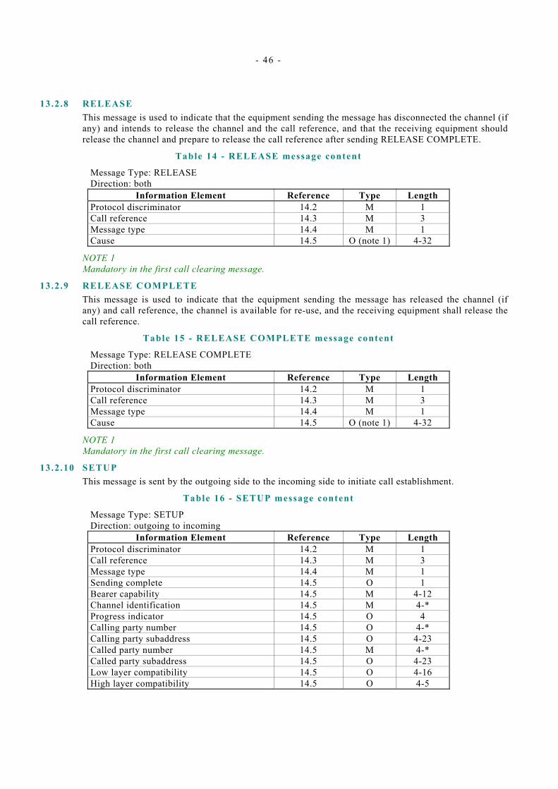
- 46 -
13.2 .8 RELEASE This message is used to indicate that the equipment sending the message has disconnected the channel (if any) and intends to release the channel and the call reference, and that the receiving equipment should release the channel and prepare to release the call reference after sending RELEASE COMPLETE.
Table 14 - RELEASE message content
Message Type: RELEASE Direction: both
Information Element Reference Type Length Protocol discriminator 14.2 M 1 Call reference 14.3 M 3 Message type 14.4 M 1 Cause 14.5 O (note 1) 4-32
NOTE 1 Mandatory in the first call clearing message.
13.2 .9 RELEASE COMPLETE This message is used to indicate that the equipment sending the message has released the channel (if any) and call reference, the channel is available for re-use, and the receiving equipment shall release the call reference.
Table 15 - RELEASE COMPLETE message content
Message Type: RELEASE COMPLETE Direction: both
Information Element Reference Type Length Protocol discriminator 14.2 M 1 Call reference 14.3 M 3 Message type 14.4 M 1 Cause 14.5 O (note 1) 4-32
NOTE 1 Mandatory in the first call clearing message.
13.2 .10 SETUP This message is sent by the outgoing side to the incoming side to initiate call establishment.
Table 16 - SETUP message content
Message Type: SETUP Direction: outgoing to incoming
Information Element Reference Type Length Protocol discriminator 14.2 M 1 Call reference 14.3 M 3 Message type 14.4 M 1 Sending complete 14.5 O 1 Bearer capability 14.5 M 4-12 Channel identification 14.5 M 4-* Progress indicator 14.5 O 4 Calling party number 14.5 O 4-* Calling party subaddress 14.5 O 4-23 Called party number 14.5 M 4-* Called party subaddress 14.5 O 4-23 Low layer compatibility 14.5 O 4-16 High layer compatibility 14.5 O 4-5

- 47 -
13.2 .11 SETUP ACKNOWLEDGE This message is sent by the incoming side to indicate that call establishment has been initiated, but additional information may be required.
Table 17 - SETUP ACKNOWLEDGE message content
Message Type: SETUP ACKNOWLEDGE Direction: incoming to outgoing
Information Element Reference Type Length Protocol discriminator 14.2 M 1 Call reference 14.3 M 3 Message type 14.4 M 1 Channel identification 14.5 M 4-*
13.3 Messages for layer management 13.3 .1 RESTART
This message is used to request the recipient to restart (i.e. return to idle condition) the indicated channel(s).
Table 18 - RESTART message content
Message Type: RESTART Direction: both
Information Element Reference Type Length Protocol discriminator 14.2 M 1 Call reference 14.3 M (note 1) 3 Message type 14.4 M 1 Channel identification 14.5 O (note 2) 4-* Restart indicator 14.5 M 3
NOTE 1 This message is sent with the global call reference.
NOTE 2 Included when the Restart indicator information element indicates that a particular channel is to be restarted.
13.3.2 RESTART ACKNOWLEDGE This message is used to acknowledge the receipt of a RESTART message and to indicate that the requested restart is complete.
Table 19 - RESTART ACKNOWLEDGE message content
Message Type: RESTART ACKNOWLEDGE Direction: both
Information Element Reference Type Length Protocol discriminator 14.2 M 1 Call reference 14.3 M (note 1) 3 Message type 14.4 M 1 Channel identification 14.5 O (note 2) 4-* Restart indicator 14.5 M 3
NOTE 1 This message is sent with the global call reference.
NOTE 2 Included when the Restart indicator information element indicates that a particular channel has been restarted.
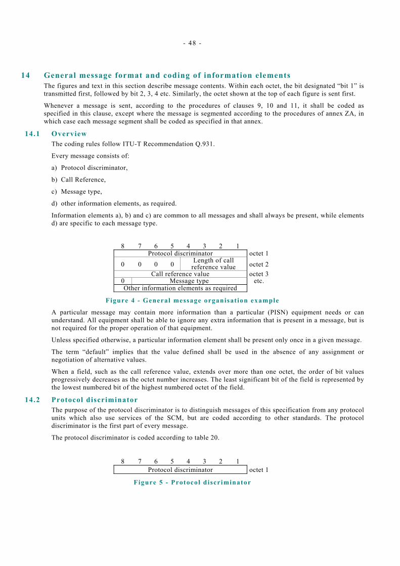
- 48 -
14 General message format and coding of information elements The figures and text in this section describe message contents. Within each octet, the bit designated “bit 1” is transmitted first, followed by bit 2, 3, 4 etc. Similarly, the octet shown at the top of each figure is sent first.
Whenever a message is sent, according to the procedures of clauses 9, 10 and 11, it shall be coded as specified in this clause, except where the message is segmented according to the procedures of annex ZA, in which case each message segment shall be coded as specified in that annex.
14.1 Overview The coding rules follow ITU-T Recommendation Q.931.
Every message consists of:
a) Protocol discriminator,
b) Call Reference,
c) Message type,
d) other information elements, as required.
Information elements a), b) and c) are common to all messages and shall always be present, while elements d) are specific to each message type.
8 7 6 5 4 3 2 1
Protocol discriminator octet 1 0 0 0 0 Length of call
reference value octet 2 Call reference value octet 3
0 Message type etc. Other information elements as required
Figure 4 - General message organisat ion example
A particular message may contain more information than a particular (PISN) equipment needs or can understand. All equipment shall be able to ignore any extra information that is present in a message, but is not required for the proper operation of that equipment.
Unless specified otherwise, a particular information element shall be present only once in a given message.
The term “default” implies that the value defined shall be used in the absence of any assignment or negotiation of alternative values.
When a field, such as the call reference value, extends over more than one octet, the order of bit values progressively decreases as the octet number increases. The least significant bit of the field is represented by the lowest numbered bit of the highest numbered octet of the field.
14.2 Protocol discriminator The purpose of the protocol discriminator is to distinguish messages of this specification from any protocol units which also use services of the SCM, but are coded according to other standards. The protocol discriminator is the first part of every message.
The protocol discriminator is coded according to table 20.
8 7 6 5 4 3 2 1 Protocol discriminator octet 1
Figure 5 - Protocol discriminator
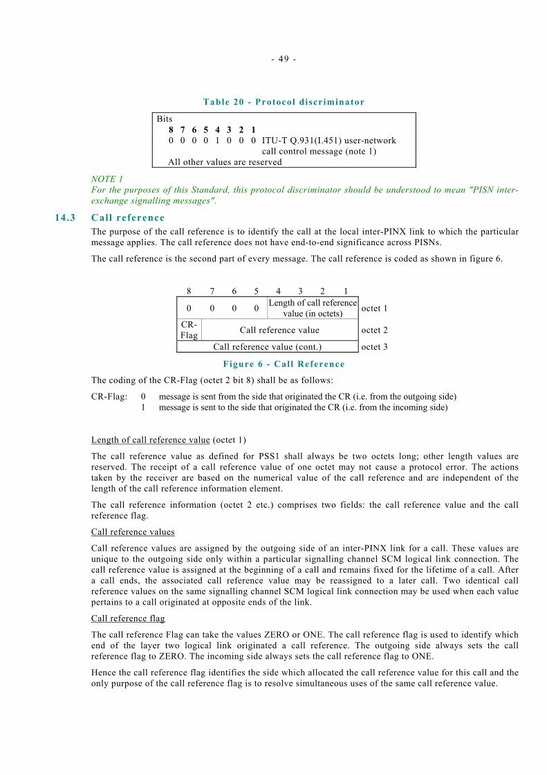
- 49 -
Table 20 - Protocol discriminator
Bits 8 7 6 5 4 3 2 1 0 0 0 0 1 0 0 0 ITU-T Q.931(I.451) user-network
call control message (note 1) All other values are reserved
NOTE 1 For the purposes of this Standard, this protocol discriminator should be understood to mean "PISN inter-exchange signalling messages".
14.3 Call reference The purpose of the call reference is to identify the call at the local inter-PINX link to which the particular message applies. The call reference does not have end-to-end significance across PISNs.
The call reference is the second part of every message. The call reference is coded as shown in figure 6.
8 7 6 5 4 3 2 1
0 0 0 0 Length of call reference value (in octets) octet 1
CR- Flag Call reference value octet 2
Call reference value (cont.) octet 3
Figure 6 - Cal l Reference
The coding of the CR-Flag (octet 2 bit 8) shall be as follows:
CR-Flag: 0 message is sent from the side that originated the CR (i.e. from the outgoing side) 1 message is sent to the side that originated the CR (i.e. from the incoming side)
Length of call reference value (octet 1)
The call reference value as defined for PSS1 shall always be two octets long; other length values are reserved. The receipt of a call reference value of one octet may not cause a protocol error. The actions taken by the receiver are based on the numerical value of the call reference and are independent of the length of the call reference information element.
The call reference information (octet 2 etc.) comprises two fields: the call reference value and the call reference flag.
Call reference values
Call reference values are assigned by the outgoing side of an inter-PINX link for a call. These values are unique to the outgoing side only within a particular signalling channel SCM logical link connection. The call reference value is assigned at the beginning of a call and remains fixed for the lifetime of a call. After a call ends, the associated call reference value may be reassigned to a later call. Two identical call reference values on the same signalling channel SCM logical link connection may be used when each value pertains to a call originated at opposite ends of the link.
Call reference flag
The call reference Flag can take the values ZERO or ONE. The call reference flag is used to identify which end of the layer two logical link originated a call reference. The outgoing side always sets the call reference flag to ZERO. The incoming side always sets the call reference flag to ONE.
Hence the call reference flag identifies the side which allocated the call reference value for this call and the only purpose of the call reference flag is to resolve simultaneous uses of the same call reference value.

- 50 -
Global call reference
The numerical value of the “global call reference” is zero. It is coded as shown in figure 7. The equipment receiving a message containing the global call reference should interpret the message as pertaining to all call references associated with the SCM connection.
8 7 6 5 4 3 2 1 0 0 0 0 0 0 1 0 octet 1
0/1 0 0 0 0 0 0 0 octet 2 0 0 0 0 0 0 0 0 octet 3
Figure 7 - Global cal l reference
Dummy call reference
The Dummy call reference consists of a single octet with all zeros as defined in ITU-T Q.931. Its use is beyond the scope of this Standard.
14.4 Message type The purpose of the message type is to identify the function of the message being sent.
The message type is the third part of every message and it is coded as shown in figure 8 and table 21.
Bit 8 is reserved for possible future use as an extension bit.
8 7 6 5 4 3 2 1 0 Message type octet 1
Figure 8 - Message Type
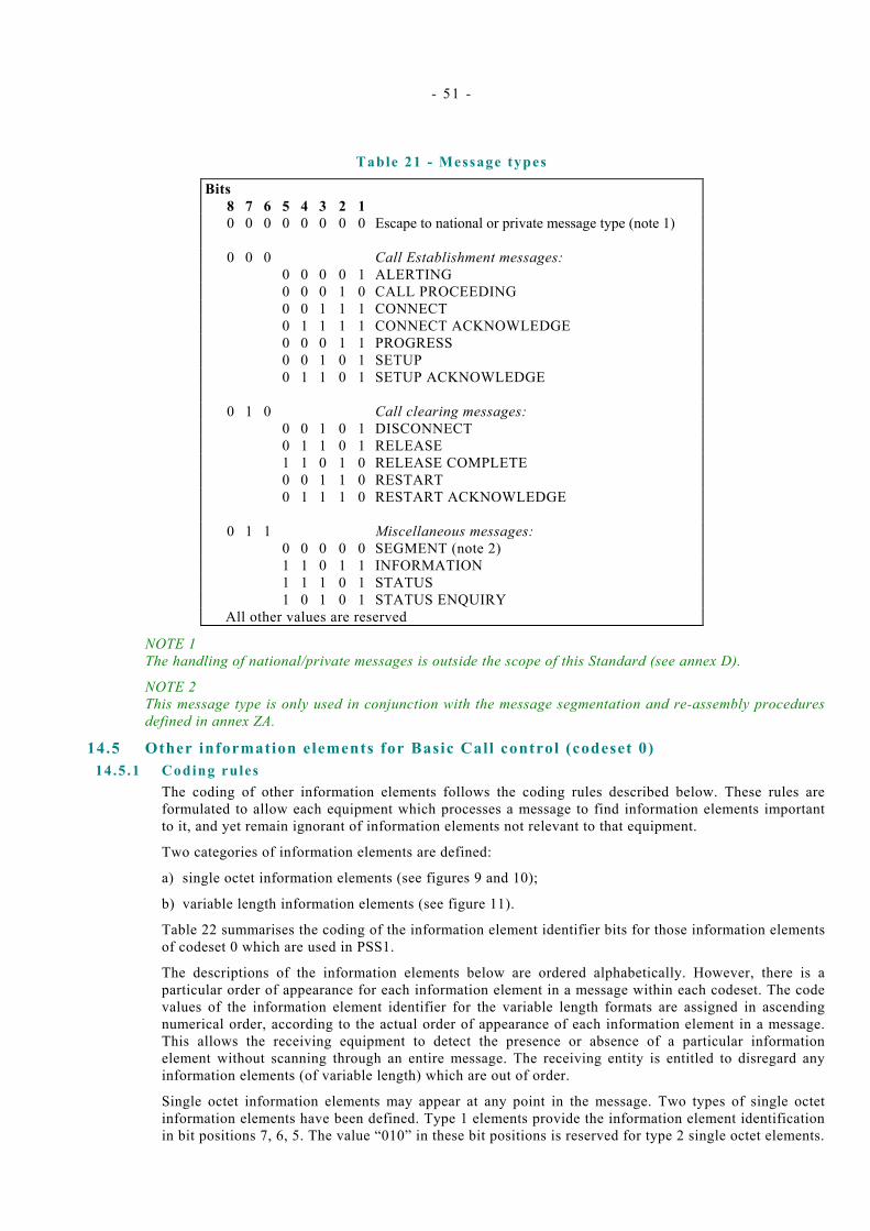
- 51 -
Table 21 - Message types
Bits 8 7 6 5 4 3 2 1 0 0 0 0 0 0 0 0 Escape to national or private message type (note 1) 0 0 0 Call Establishment messages: 0 0 0 0 1 ALERTING 0 0 0 1 0 CALL PROCEEDING 0 0 1 1 1 CONNECT 0 1 1 1 1 CONNECT ACKNOWLEDGE 0 0 0 1 1 PROGRESS 0 0 1 0 1 SETUP 0 1 1 0 1 SETUP ACKNOWLEDGE 0 1 0 Call clearing messages: 0 0 1 0 1 DISCONNECT 0 1 1 0 1 RELEASE 1 1 0 1 0 RELEASE COMPLETE 0 0 1 1 0 RESTART 0 1 1 1 0 RESTART ACKNOWLEDGE 0 1 1 Miscellaneous messages: 0 0 0 0 0 SEGMENT (note 2) 1 1 0 1 1 INFORMATION 1 1 1 0 1 STATUS 1 0 1 0 1 STATUS ENQUIRY All other values are reserved
NOTE 1 The handling of national/private messages is outside the scope of this Standard (see annex D).
NOTE 2 This message type is only used in conjunction with the message segmentation and re-assembly procedures defined in annex ZA.
14.5 Other information elements for Basic Call control (codeset 0) 14.5 .1 Coding rules
The coding of other information elements follows the coding rules described below. These rules are formulated to allow each equipment which processes a message to find information elements important to it, and yet remain ignorant of information elements not relevant to that equipment.
Two categories of information elements are defined:
a) single octet information elements (see figures 9 and 10);
b) variable length information elements (see figure 11).
Table 22 summarises the coding of the information element identifier bits for those information elements of codeset 0 which are used in PSS1.
The descriptions of the information elements below are ordered alphabetically. However, there is a particular order of appearance for each information element in a message within each codeset. The code values of the information element identifier for the variable length formats are assigned in ascending numerical order, according to the actual order of appearance of each information element in a message. This allows the receiving equipment to detect the presence or absence of a particular information element without scanning through an entire message. The receiving entity is entitled to disregard any information elements (of variable length) which are out of order.
Single octet information elements may appear at any point in the message. Two types of single octet information elements have been defined. Type 1 elements provide the information element identification in bit positions 7, 6, 5. The value “010” in these bit positions is reserved for type 2 single octet elements.

- 52 -
Where the description of information elements in this specification contains spare bits, these bits are indicated as being set to “ZERO”. In order to allow compatibility with future implementations, message should not be rejected simply because a spare bit is set to “ONE”.
The second octet of a variable length information element indicates the total length of the contents of that information element (i.e. the length starting with octet 3). It is the binary coding of the number of octets of the contents, with bit 1 as the least significant bit (20).
An optional variable length information element may be present, but empty. For example, a SETUP message may contain a calling party number information element, the content of which is of zero length. This should be interpreted by the receiver as equivalent to that information element being absent. Similarly, an absent information element should be interpreted by the receiver as equivalent to that information element being empty.
The following rules apply for the coding of the contents of variable length information elements (octets 3 etc.):
a) The first digit in the octet number identifies one octet or a group of octets (i.e. the octets are numbered in a way that reflects the structuring of an information element into groups of one or more octets).
b) Each octet group is a self contained entity. The internal structure of an octet group may be defined in alternative ways.
c) An octet group is formed by using some extension mechanism. The preferred extension mechanism is to extend an octet (N) to the next octet(s) (Na, Nb, etc.) by using bit 8 in each octet as an extension bit. The bit value “ZERO” indicates that the octet continues through the next octet. The bit value “ONE” indicates that this octet is the last octet of the group. If one octet (e.g. Nb) is present, the preceding octets (N and Na) must also be present.
In the format descriptions of the following paragraphs, bit 8 is marked “0/1 ext” if another octet follows. Bit 8 is marked “1” or “1 ext” if this is the last octet in the extension domain (octet group).
Additional octets may be defined later (“1 ext” changed to “0/1 ext”) and equipments shall be prepared to receive such additional octets, although the equipment need not be able to interpret or act upon the content of these octets.
d) In addition to the extension mechanism defined above, an octet (N) may be extended through the next octet(s) (N.1, N.2 etc.) by indications in bits 7-1 of octet N.
e) The mechanisms in c) and d) may be combined.
f) Optional octets are marked with asterisks (*).
8 7 6 5 4 3 2 1 1 Information
element identifierContents of
information elementoctet 1
Figure 9 - Single octet information element format ( type 1)
8 7 6 5 4 3 2 1 1 0 1 0 x x x x octet 1 Information element identifier
Figure 10 - Single octet information element format ( type 2)
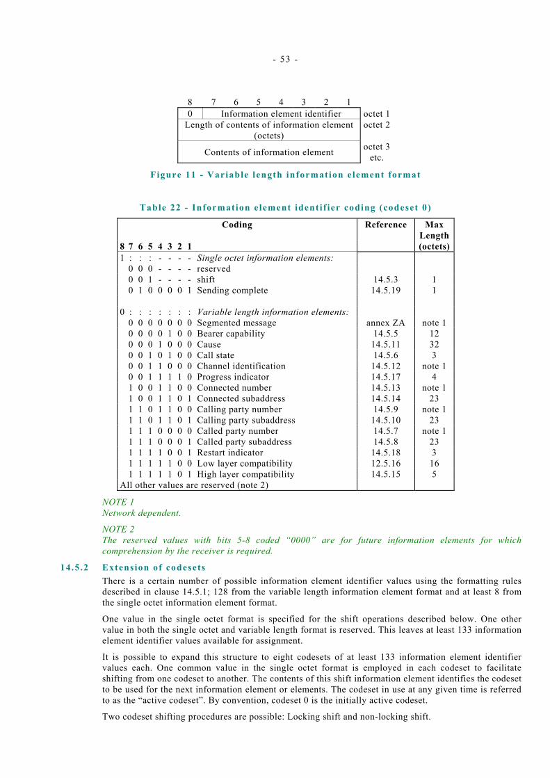
- 53 -
8 7 6 5 4 3 2 1 0 Information element identifier octet 1
Length of contents of information element (octets)
octet 2
Contents of information element octet 3 etc.
Figure 11 - Variable length information element format
Table 22 - Information element identi f ier coding (codeset 0)
Coding Reference Max Length
8 7 6 5 4 3 2 1 (octets)1 : : : - - - - Single octet information elements: 0 0 0 - - - - reserved 0 0 1 - - - - shift 14.5.3 1 0 1 0 0 0 0 1 Sending complete 14.5.19 1 0 : : : : : : : Variable length information elements: 0 0 0 0 0 0 0 Segmented message annex ZA note 1 0 0 0 0 1 0 0 Bearer capability 14.5.5 12 0 0 0 1 0 0 0 Cause 14.5.11 32 0 0 1 0 1 0 0 Call state 14.5.6 3 0 0 1 1 0 0 0 Channel identification 14.5.12 note 1 0 0 1 1 1 1 0 Progress indicator 14.5.17 4 1 0 0 1 1 0 0 Connected number 14.5.13 note 1 1 0 0 1 1 0 1 Connected subaddress 14.5.14 23 1 1 0 1 1 0 0 Calling party number 14.5.9 note 1 1 1 0 1 1 0 1 Calling party subaddress 14.5.10 23 1 1 1 0 0 0 0 Called party number 14.5.7 note 1 1 1 1 0 0 0 1 Called party subaddress 14.5.8 23 1 1 1 1 0 0 1 Restart indicator 14.5.18 3 1 1 1 1 1 0 0 Low layer compatibility 12.5.16 16 1 1 1 1 1 0 1 High layer compatibility 14.5.15 5 All other values are reserved (note 2)
NOTE 1 Network dependent.
NOTE 2 The reserved values with bits 5-8 coded “0000” are for future information elements for which comprehension by the receiver is required.
14.5 .2 Extension of codesets There is a certain number of possible information element identifier values using the formatting rules described in clause 14.5.1; 128 from the variable length information element format and at least 8 from the single octet information element format.
One value in the single octet format is specified for the shift operations described below. One other value in both the single octet and variable length format is reserved. This leaves at least 133 information element identifier values available for assignment.
It is possible to expand this structure to eight codesets of at least 133 information element identifier values each. One common value in the single octet format is employed in each codeset to facilitate shifting from one codeset to another. The contents of this shift information element identifies the codeset to be used for the next information element or elements. The codeset in use at any given time is referred to as the “active codeset”. By convention, codeset 0 is the initially active codeset.
Two codeset shifting procedures are possible: Locking shift and non-locking shift.
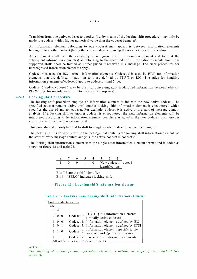
- 54 -
Transition from one active codeset to another (i.e. by means of the locking shift procedure) may only be made to a codeset with a higher numerical value than the codeset being left.
An information element belonging to one codeset may appear in between information elements belonging to another codeset (being the active codeset) by using the non-locking shift procedure.
An equipment shall have the capability to recognise a shift information element and to treat the subsequent information element(s) as belonging to the specified shift. Information elements from non-supported shifts shall be treated as unrecognised if received in a message. The error procedures for unrecognised information elements apply.
Codeset 4 is used for ISO defined information elements. Codeset 5 is used by ETSI for information elements that are defined in addition to those defined by ITU-T or ISO. The rules for handling information elements of codeset 0 apply to codesets 4 and 5 too.
Codeset 6 and/or codeset 7 may be used for conveying non-standardised information between adjacent PINXs (e.g. for manufacturer or network specific purposes).
14.5.3 Locking shif t procedure The locking shift procedure employs an information element to indicate the new active codeset. The specified codeset remains active until another locking shift information element is encountered which specifies the use of another codeset. For example, codeset 0 is active at the start of message content analysis. If a locking shift to another codeset is encountered, the next information elements will be interpreted according to the information element identifiers assigned in the new codeset, until another shift information element is encountered.
This procedure shall only be used to shift to a higher order codeset than the one being left.
The locking shift is valid only within the message that contains the locking shift information element. At the start of every message content analysis, the active codeset is codeset 0.
The locking shift information element uses the single octet information element format and is coded as shown in figure 12 and table 23.
8 7 6 5 4 3 2 1 1 0 0 1 0 New codeset
identification octet 1
Bits 7-5 are the shift identifier
Bit 4 = “ZERO” indicates locking shift
Figure 12 - Locking shift information element
Table 23 - Locking/non-locking shift information element
Codeset identification Bits 3 2 1 0 0 0 Codeset 0: ITU-T Q.931 information elements
(initially active codeset) 1 0 0 Codeset 4: Information elements defined by ISO 1 0 1 Codeset 5: Information elements defined by ETSI 1 1 0 Codeset 6: Information elements specific to the
local network (public or private) 1 1 1 Codeset 7: User-specific information elements
All other values are reserved (note 1)
NOTE 1 The handling of national/private information elements is outside the scope of this Standard (see annex D).

- 55 -
14.5 .4 Non-locking shif t procedure The non-locking shift procedure provides a temporary shift to the specified lower or higher codeset. It uses a single octet information element to indicate the codeset to be used to interpret the next single information element. After the interpretation of that information element, the active codeset is again used for interpreting any following information elements. For example, codeset 0 is active at the beginning of message content analysis. If a non-locking shift to another codeset is encountered, only the next information element is interpreted according to the information element identifiers assigned in that codeset. After that codeset 0 will again be used to interpret the following information elements. A non-locking shift information element indicating the current codeset shall not be regarded as an error.
A locking shift information element shall not follow directly on a non-locking shift information element. If this combination is received it shall be interpreted as though a locking shift information element only had been received.
The single octet non-locking shift information element format and coding is shown in figure 13 and table 23.
8 7 6 5 4 3 2 1
1 0 0 1 1 Temporary codeset
identification
octet 1
Bits 7-5 are the shift identifier
Bit 4 = “ONE” indicates non-locking shift
Figure 13 - Non-locking shift information element
14.5 .5 Bearer capabi l i ty The purpose of the bearer capability information element is to indicate a requested ECMA-142or ISO/IEC 11584 bearer capability to be provided by the network.
The bearer capability information element is coded as shown in figure 14 and table 24.
NOTE This encoding represents a subset of ITU-T Rec. Q.931.
8 7 6 5 4 3 2 1 Bearer capability
0 0 0 0 0 1 0 0 octet 1 Information element identifier
Length of bearer capability contents octet 2 1
ext Coding
standard Information transfer
capability octet 3
1 ext
Transfer mode Information transfer rate octet 4
note 1 1
ext Multiplier octet 4.1* note 2
0/1 0 1 User information octet 5* ext Layer ID(1) layer 1 protocol note 3
NOTE 1 - As only default values are used for all fields of ITU–T Rec. Q.931 octets 4a and 4b, these octets shall not be used. The following values shall be assumed:
Structure: circuit mode: 8kHz integrity Configuration: point-to-point Establishment: demand Symmetry: bidirectional symmetric
NOTE 2 - This octet shall be included if the Information transfer rate in octet 4 indicates ‘multi-rate’. Otherwise, it shall not be included.

- 56 -
NOTE 3 - The contents of optional octets 5a, 5b, 5c, 5d, 6 and 7 have no impact at the Q reference point, and are therefore not specified in this Standard. One or more of these octets may be included, in accordance with ITU-T Rec. Q.931. Receipt of any of these octets regardless of content shall not cause a protocol error.
Figure 14 - Bearer capabi l i ty information element
Table 24 - Bearer capabi l i ty information element
Coding standard (octet 3) Bits 7 6 0 0 CCITT standardized coding
All other values are reserved Information transfer capability (octet 3) Bits 5 4 3 2 1 0 0 0 0 0 Speech 0 1 0 0 0 unrestricted digital information 0 1 0 0 1 Restricted digital information (applicable
only in interworking situations) 1 0 0 0 0 3.1 kHz audio 1 0 0 0 1 Unrestricted digital information with tones /
announcements All other values are reserved Transfer mode(octet 4) Bits 7 6 0 0 circuit mode
All other values are reserved Information transfer rate (octet 4) Bits 5 4 3 2 1 1 0 0 0 0 64 kbit/s 1 0 0 1 1 384 kbit/s (note 1) 1 0 1 0 1 1536 kbit/s (note 1) 1 0 1 1 1 1920 kbit/s (note 1) 1 1 0 0 0 multi-rate (64 kbit/s base rate) (note 2)
All other values are reserved Multiplier (octet 4.1) Bits 7 6 5 4 3 2 1 0 0 0 0 0 1 0 2 0 0 0 0 0 1 1 3 0 0 0 0 1 0 0 4 0 0 0 0 1 0 1 5 0 0 0 0 1 1 0 6 0 0 0 0 1 1 1 7 0 0 0 1 0 0 0 8 0 0 0 1 0 0 1 9 0 0 0 1 0 1 0 10 0 0 0 1 0 1 1 11 0 0 0 1 1 0 0 12 0 0 0 1 1 0 1 13
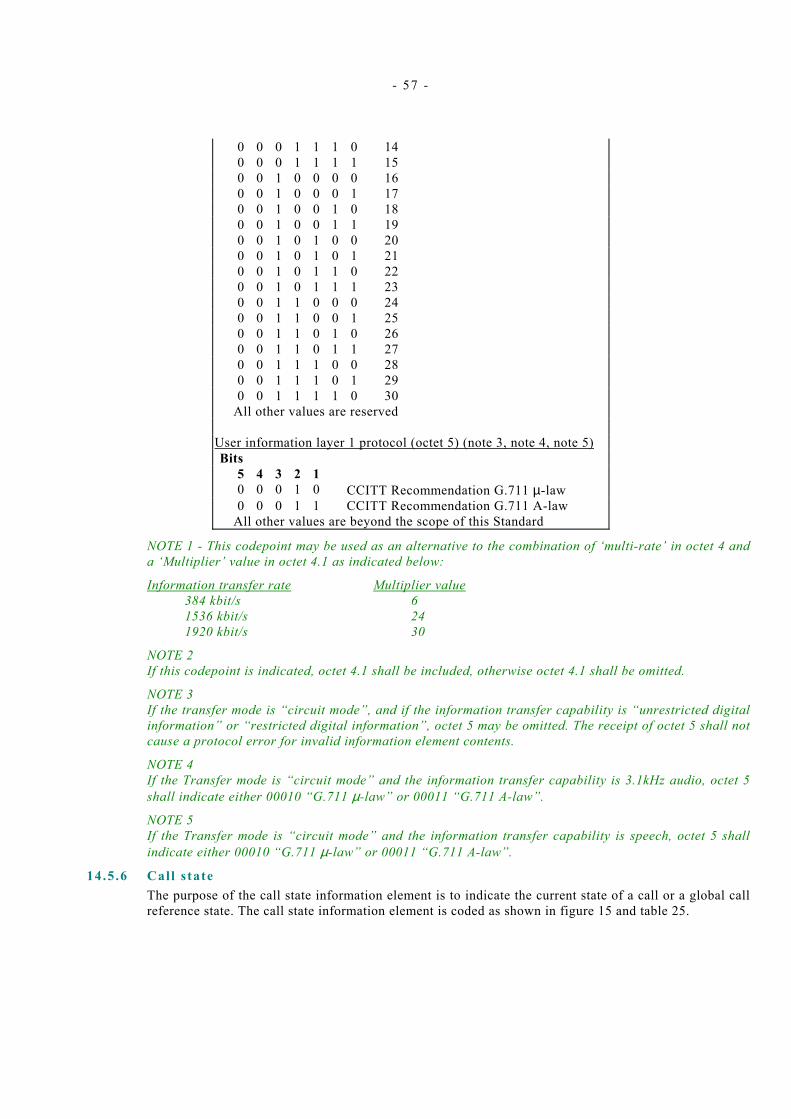
- 57 -
0 0 0 1 1 1 0 14 0 0 0 1 1 1 1 15 0 0 1 0 0 0 0 16 0 0 1 0 0 0 1 17 0 0 1 0 0 1 0 18 0 0 1 0 0 1 1 19 0 0 1 0 1 0 0 20 0 0 1 0 1 0 1 21 0 0 1 0 1 1 0 22 0 0 1 0 1 1 1 23 0 0 1 1 0 0 0 24 0 0 1 1 0 0 1 25 0 0 1 1 0 1 0 26 0 0 1 1 0 1 1 27 0 0 1 1 1 0 0 28 0 0 1 1 1 0 1 29 0 0 1 1 1 1 0 30
All other values are reserved User information layer 1 protocol (octet 5) (note 3, note 4, note 5) Bits 5 4 3 2 1 0 0 0 1 0 CCITT Recommendation G.711 µ-law 0 0 0 1 1 CCITT Recommendation G.711 A-law
All other values are beyond the scope of this Standard
NOTE 1 - This codepoint may be used as an alternative to the combination of ‘multi-rate’ in octet 4 and a ‘Multiplier’ value in octet 4.1 as indicated below:
Information transfer rate Multiplier value 384 kbit/s 6 1536 kbit/s 24 1920 kbit/s 30
NOTE 2 If this codepoint is indicated, octet 4.1 shall be included, otherwise octet 4.1 shall be omitted.
NOTE 3 If the transfer mode is “circuit mode”, and if the information transfer capability is “unrestricted digital information” or “restricted digital information”, octet 5 may be omitted. The receipt of octet 5 shall not cause a protocol error for invalid information element contents.
NOTE 4 If the Transfer mode is “circuit mode” and the information transfer capability is 3.1kHz audio, octet 5 shall indicate either 00010 “G.711 µ-law” or 00011 “G.711 A-law”.
NOTE 5 If the Transfer mode is “circuit mode” and the information transfer capability is speech, octet 5 shall indicate either 00010 “G.711 µ-law” or 00011 “G.711 A-law”.
14.5 .6 Call s tate The purpose of the call state information element is to indicate the current state of a call or a global call reference state. The call state information element is coded as shown in figure 15 and table 25.

- 58 -
8 7 6 5 4 3 2 1 Call state
0 0 0 1 0 1 0 0 octet 1 Information element identifier
Length of call state contents) octet 2Coding
Standard Call state value/
Global call reference state valueoctet 3
Figure 15 - Cal l s tate information element
Table 25 - Cal l s tate information element
Coding standard (octet 3) Bits 8 7 0 0 CCITT standardized coding
All other values are reserved Call state value (octet 3) Bits 6 5 4 3 2 1 Value Circuit Mode Protocol Control State 0 0 0 0 0 0 0 Null 0 0 0 0 0 1 1 Call initiated 0 0 0 0 1 0 2 Overlap sending (note 1) 0 0 0 0 1 1 3 Outgoing call proceeding 0 0 0 1 0 0 4 Call delivered 0 0 0 1 1 0 6 Call present 0 0 0 1 1 1 7 Call received 0 0 1 0 0 0 8 Connect request 0 0 1 0 0 1 9 Incoming call proceeding 0 0 1 0 1 0 10 Active 0 0 1 0 1 1 11 Disconnect Request 0 0 1 1 0 0 12 Disconnect Indication 0 1 0 0 1 1 19 Release request 0 1 1 0 0 1 25 Overlap receiving (note 1)
Global call reference state value(octet 3) Bits 6 5 4 3 2 1 State 0 0 0 0 0 0 REST 0 - null 1 1 1 1 0 1 REST 1 - restart request 1 1 1 1 1 0 REST 2 -restart
NOTE 1 If enbloc signalling only is used between two adjacent PINXs, overlap receiving procedures need not be tested.
14.5 .7 Called party number The purpose of the called party number information element is to identify the called party of a call. The called party number information element is coded as shown in figure 16 and table 26.
The maximum length of the called party number information element is network dependent and therefore outside the scope of this Standard.
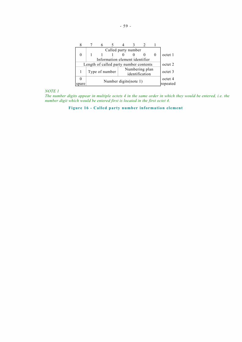
- 59 -
8 7 6 5 4 3 2 1 Called party number
0 1 1 1 0 0 0 0 octet 1 Information element identifier
Length of called party number contents octet 2
1 Type of number Numbering plan identification octet 3
0 spare Number digits(note 1) octet 4
repeated
NOTE 1 The number digits appear in multiple octets 4 in the same order in which they would be entered, i.e. the number digit which would be entered first is located in the first octet 4.
Figure 16 - Cal led party number information element
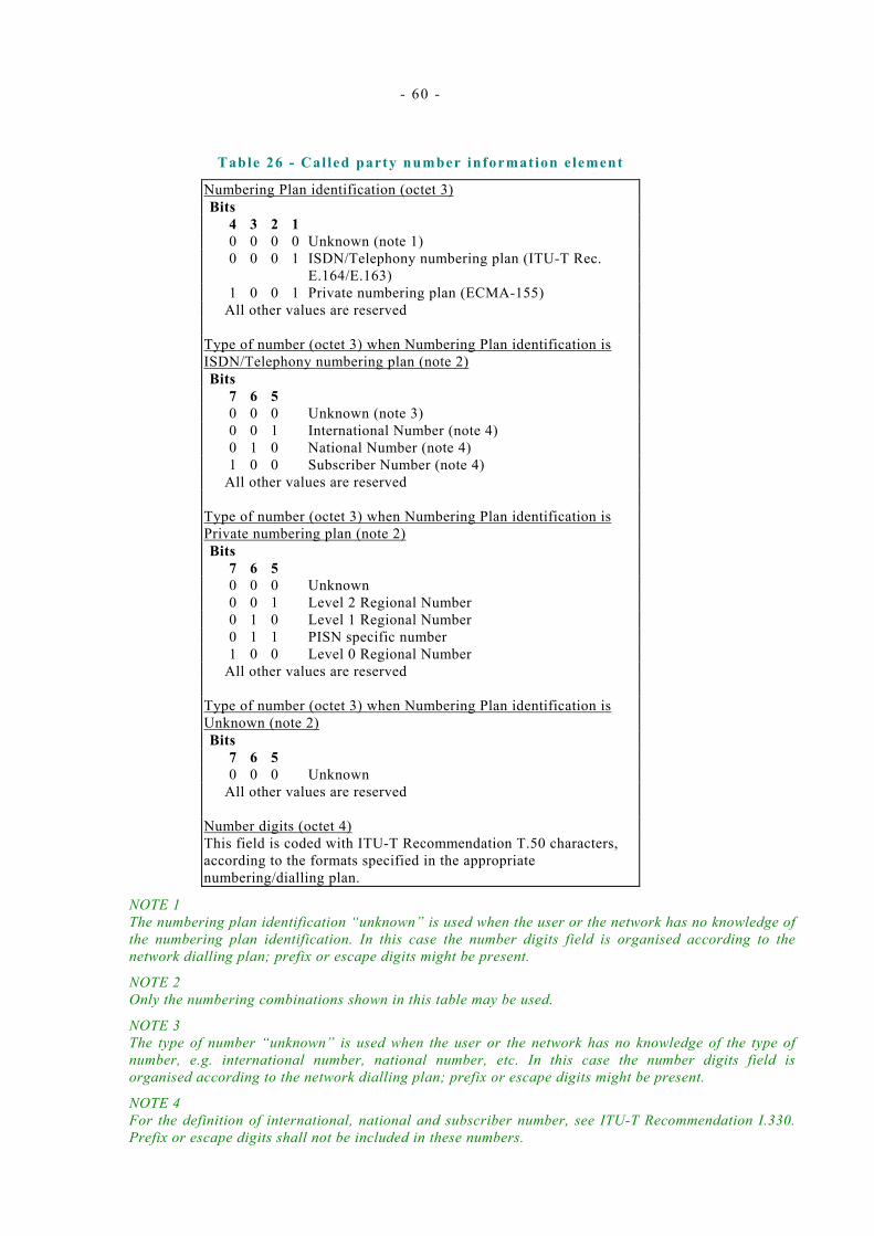
- 60 -
Table 26 - Cal led party number information element
Numbering Plan identification (octet 3) Bits 4 3 2 1 0 0 0 0 Unknown (note 1) 0 0 0 1 ISDN/Telephony numbering plan (ITU-T Rec.
E.164/E.163) 1 0 0 1 Private numbering plan (ECMA-155)
All other values are reserved Type of number (octet 3) when Numbering Plan identification is ISDN/Telephony numbering plan (note 2) Bits 7 6 5 0 0 0 Unknown (note 3) 0 0 1 International Number (note 4) 0 1 0 National Number (note 4) 1 0 0 Subscriber Number (note 4)
All other values are reserved Type of number (octet 3) when Numbering Plan identification is Private numbering plan (note 2) Bits 7 6 5 0 0 0 Unknown 0 0 1 Level 2 Regional Number 0 1 0 Level 1 Regional Number 0 1 1 PISN specific number 1 0 0 Level 0 Regional Number
All other values are reserved Type of number (octet 3) when Numbering Plan identification is Unknown (note 2) Bits 7 6 5 0 0 0 Unknown
All other values are reserved Number digits (octet 4) This field is coded with ITU-T Recommendation T.50 characters, according to the formats specified in the appropriate numbering/dialling plan.
NOTE 1 The numbering plan identification “unknown” is used when the user or the network has no knowledge of the numbering plan identification. In this case the number digits field is organised according to the network dialling plan; prefix or escape digits might be present.
NOTE 2 Only the numbering combinations shown in this table may be used.
NOTE 3 The type of number “unknown” is used when the user or the network has no knowledge of the type of number, e.g. international number, national number, etc. In this case the number digits field is organised according to the network dialling plan; prefix or escape digits might be present.
NOTE 4 For the definition of international, national and subscriber number, see ITU-T Recommendation I.330. Prefix or escape digits shall not be included in these numbers.

- 61 -
14.5 .8 Called party subaddress The purpose of the called party subaddress information element is to identify the subaddress of the called party of a call.
NOTE 1 For the definition of subaddress, see ECMA-155.
Refer to ITU-T Rec. Q.931 for coding rules for this information element.
The maximum length of the called party subaddress information element is 23 octets.
NOTE 2 The encoding of this information element is not specified in this Standard for it is defined as transparent to the PSS1 protocol.
14.5 .9 Cal l ing party number The purpose of the calling party number information element is to identify the origin of a call.
The calling party number information element is coded as shown in figure 17 and table 27.
The maximum length of the calling party number information element is network dependent and therefore outside the scope of this Standard.
8 7 6 5 4 3 2 1 Calling party number
0 1 1 0 1 1 0 0 octet 1 Information element identifier
Length of calling party number contents octet 2 (note 1)
0/1 ext Type of number Numbering plan
identification octet 3 (note 1)
1 Presentation 0 0 0 Screening octet 3a*ext indicator Spare indicator (note 1) 0
spare Number digits octet 4 * (repeated)
NOTE 1 Octets 2, 3 and 4 of this information element are coded as in the “called party number” information element.
Figure 17 - Cal l ing party number information element
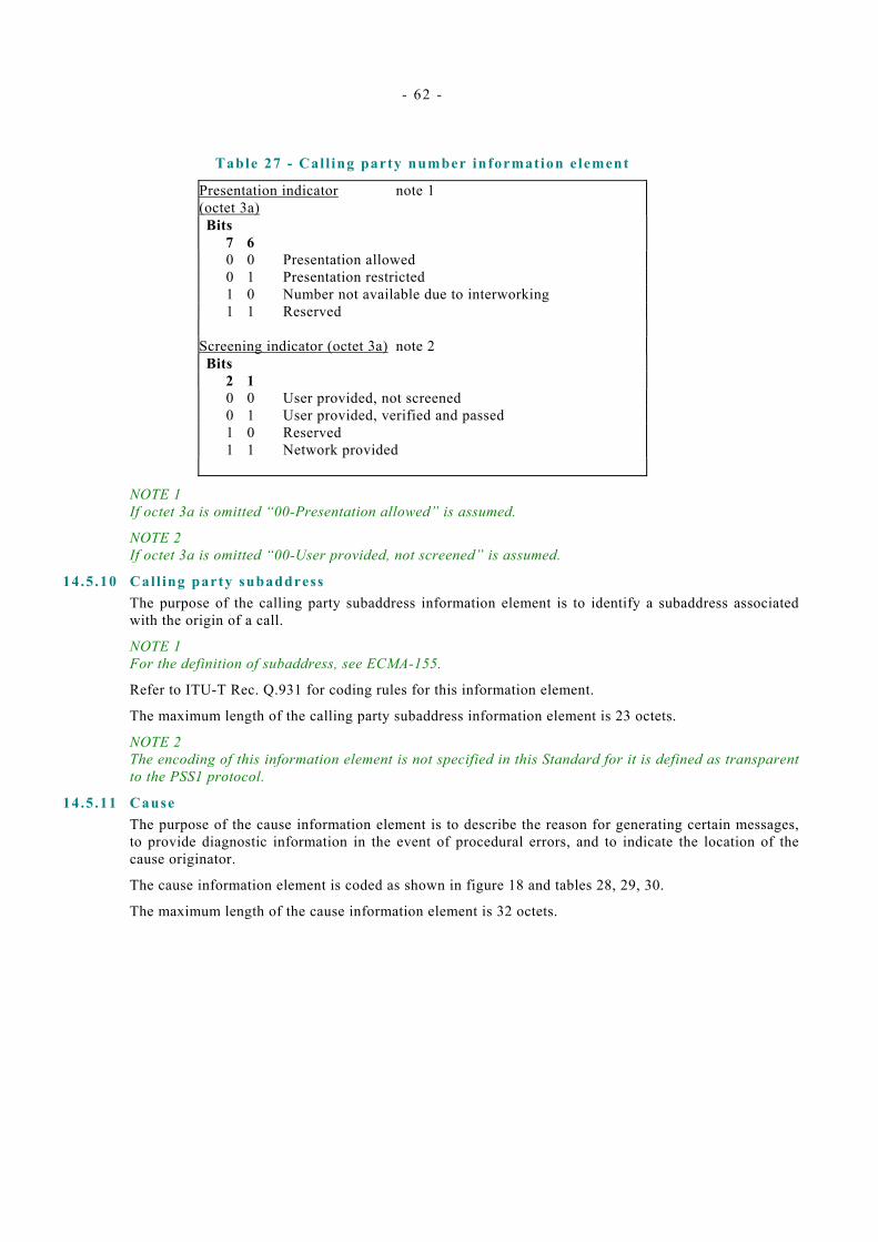
- 62 -
Table 27 - Cal l ing party number information element
Presentation indicator (octet 3a)
note 1
Bits 7 6 0 0 Presentation allowed 0 1 Presentation restricted 1 0 Number not available due to interworking 1 1 Reserved
Screening indicator (octet 3a) note 2 Bits 2 1 0 0 User provided, not screened 0 1 User provided, verified and passed 1 0 Reserved 1 1 Network provided
NOTE 1 If octet 3a is omitted “00-Presentation allowed” is assumed.
NOTE 2 If octet 3a is omitted “00-User provided, not screened” is assumed.
14.5 .10 Cal l ing party subaddress The purpose of the calling party subaddress information element is to identify a subaddress associated with the origin of a call.
NOTE 1 For the definition of subaddress, see ECMA-155.
Refer to ITU-T Rec. Q.931 for coding rules for this information element.
The maximum length of the calling party subaddress information element is 23 octets.
NOTE 2 The encoding of this information element is not specified in this Standard for it is defined as transparent to the PSS1 protocol.
14.5 .11 Cause The purpose of the cause information element is to describe the reason for generating certain messages, to provide diagnostic information in the event of procedural errors, and to indicate the location of the cause originator.
The cause information element is coded as shown in figure 18 and tables 28, 29, 30.
The maximum length of the cause information element is 32 octets.
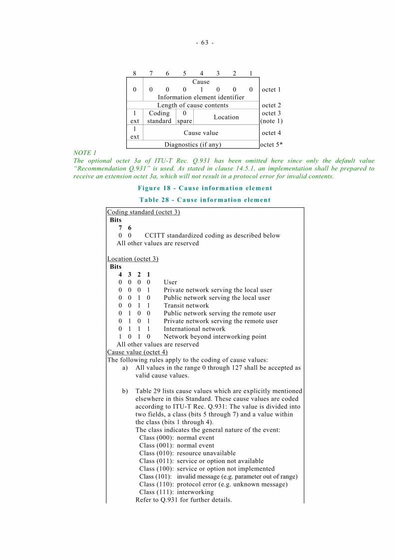
- 63 -
8 7 6 5 4 3 2 1 Cause
0 0 0 0 1 0 0 0 octet 1 Information element identifier
Length of cause contents octet 2 1
ext Coding
standard 0
spare Location octet 3 (note 1)
1 ext Cause value octet 4
Diagnostics (if any) octet 5*NOTE 1 The optional octet 3a of ITU-T Rec. Q.931 has been omitted here since only the default value “Recommendation Q.931” is used. As stated in clause 14.5.1, an implementation shall be prepared to receive an extension octet 3a, which will not result in a protocol error for invalid contents.
Figure 18 - Cause information element
Table 28 - Cause information element
Coding standard (octet 3) Bits 7 6 0 0 CCITT standardized coding as described below
All other values are reserved Location (octet 3) Bits 4 3 2 1 0 0 0 0 User 0 0 0 1 Private network serving the local user 0 0 1 0 Public network serving the local user 0 0 1 1 Transit network 0 1 0 0 Public network serving the remote user 0 1 0 1 Private network serving the remote user 0 1 1 1 International network 1 0 1 0 Network beyond interworking point
All other values are reserved Cause value (octet 4) The following rules apply to the coding of cause values: a) All values in the range 0 through 127 shall be accepted as
valid cause values.
b) Table 29 lists cause values which are explicitly mentioned elsewhere in this Standard. These cause values are coded according to ITU-T Rec. Q.931: The value is divided into two fields, a class (bits 5 through 7) and a value within the class (bits 1 through 4). The class indicates the general nature of the event: Class (000): normal event Class (001): normal event Class (010): resource unavailable Class (011): service or option not available Class (100): service or option not implemented Class (101): invalid message (e.g. parameter out of range) Class (110): protocol error (e.g. unknown message) Class (111): interworking Refer to Q.931 for further details.
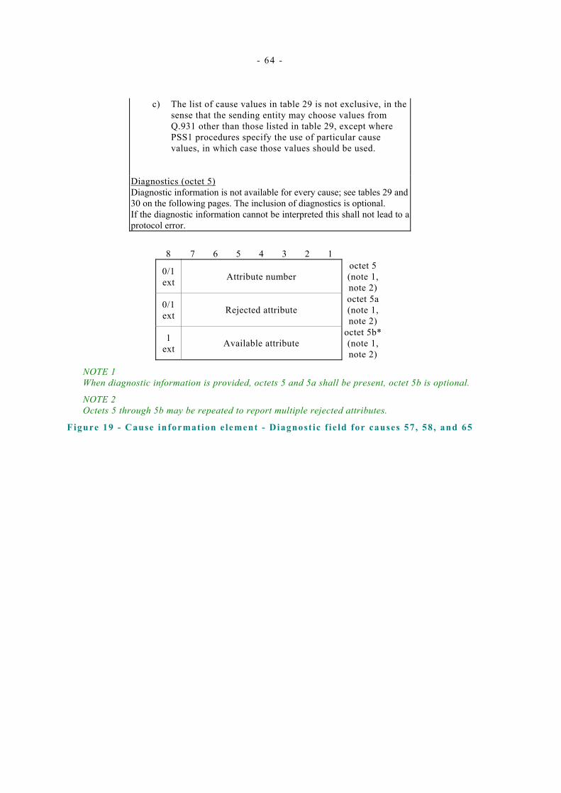
- 64 -
c) The list of cause values in table 29 is not exclusive, in the sense that the sending entity may choose values from Q.931 other than those listed in table 29, except where PSS1 procedures specify the use of particular cause values, in which case those values should be used.
Diagnostics (octet 5) Diagnostic information is not available for every cause; see tables 29 and 30 on the following pages. The inclusion of diagnostics is optional. If the diagnostic information cannot be interpreted this shall not lead to a protocol error.
8 7 6 5 4 3 2 1
0/1 ext
Attribute number
octet 5 (note 1, note 2)
0/1 ext
Rejected attribute
octet 5a (note 1, note 2)
1 ext
Available attribute
octet 5b* (note 1, note 2)
NOTE 1 When diagnostic information is provided, octets 5 and 5a shall be present, octet 5b is optional.
NOTE 2 Octets 5 through 5b may be repeated to report multiple rejected attributes.
Figure 19 - Cause information element - Diagnost ic f ie ld for causes 57, 58, and 65

- 65 -
Table 29 - Cause information element
Cause value Cause Cause Diagnostics Class Value no. 765 4321 000 0001 1. Unallocated (unassigned) number note 1 000 0011 3. No route to destination note 1 000 0110 6. Channel unacceptable ---- 001 0000 16. Normal call clearing note 1 001 0001 17. User busy ---- 001 0010 18. No user responding ---- 001 0011 19. No answer from user (user alerted) ----
001 0101 21. Call rejected User supplied diagnostics note 1, note 2
001 0110 22. Number changed New destination note 3 001 1011 27. Destination out of order ---- 001 1100 28. Invalid number format ---- 001 1110 30. Response to STATUS ENQUIRY ---- 001 1111 31. Normal, unspecified ---- 010 0010 34. No circuit/channel available ---- 010 1001 41. Temporary failure ---- 010 1100 44. Requested circuit/channel not available ---- 011 1001 57. Bearer capability not authorized note 4 011 1010 58. Bearer capability not presently available note 4 011 1111 63. Service or option not available, unspecified ---- 100 0001 65. Bearer capability not implemented note 4 101 0001 81. Invalid call reference value ---- 101 0010 82. Identified channel does not exist ---- 101 1000 88. Incompatible destination Incomp. param. note 5. 110 0000 96. Mandatory information element is missing Info elem ID(s) note 6 110 0001 97. Message type non-existent or not
implemented Message type
110 0010 98. Message not compatible with call state or message non-existent or not implemented Message type
110 0011 99. Information element non-existent or not implemented
Info elem ID(s) note 6, note 7
110 0100 100. Invalid information element contents Info elem ID(s) note 6 110 0101 101. Message not compatible with call state Message type 110 0110 102. Recovery on timer expiry Timer number note 8 110 1111 111. Protocol error, unspecified ---
NOTE 1 The following coding is used:
Bit 7 - 3: 00000 Bit 2 - 1: persistence of condition as follows:
00 - unknown 01 - permanent
Bit 8: 1
10 - transient
NOTE 2 User supplied diagnostics field is encoded according to the user specification, subject to the maximum length of the cause information element. The coding of the user supplied diagnostics should be made in such a way that it does not conflict with the coding described in note 1.
NOTE 3 “New destination” is formatted as called party information element, including the information element identifier.
- 66 -
NOTE 4 The format of the diagnostic field for cause number 57, 58, and 65 is as shown in figure 19 and in table 30.
NOTE 5 Incompatible information element identifier.
NOTE 6
a) Locking and non-locking shift procedures are applied.
b) In principle, information element identifiers are ordered in the same order as the information elements in the received message.
NOTE 7 When only a locking shift information element is included and no variable length information element identifier follows, it means that the codeset in the locking shift itself is not implemented.
NOTE 8 The timer is coded in ITU-T Recommendation T.50 characters, e.g. T308 is coded as “3” “0” “8” in bits 7-1 of octets 5, 5a, and 5b, with bit 8 being ZERO (spare).
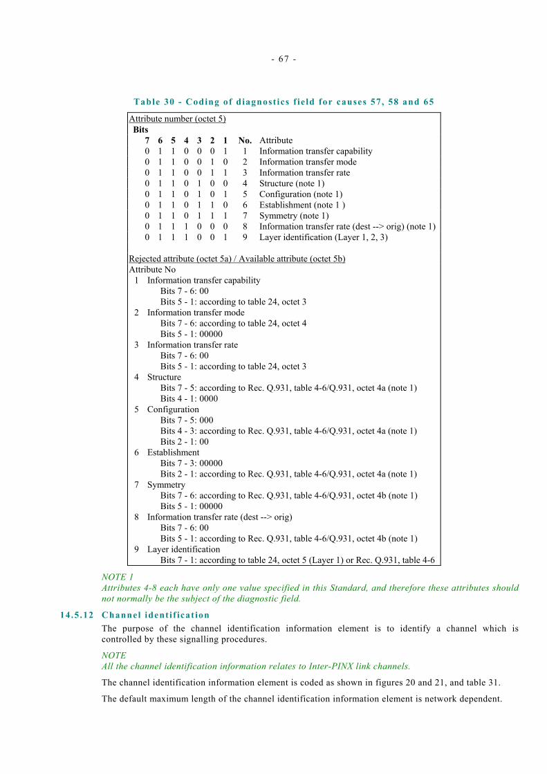
- 67 -
Table 30 - Coding of diagnost ics f ie ld for causes 57, 58 and 65
Attribute number (octet 5) Bits 7 6 5 4 3 2 1 No. Attribute 0 1 1 0 0 0 1 1 Information transfer capability 0 1 1 0 0 1 0 2 Information transfer mode 0 1 1 0 0 1 1 3 Information transfer rate 0 1 1 0 1 0 0 4 Structure (note 1) 0 1 1 0 1 0 1 5 Configuration (note 1) 0 1 1 0 1 1 0 6 Establishment (note 1 ) 0 1 1 0 1 1 1 7 Symmetry (note 1) 0 1 1 1 0 0 0 8 Information transfer rate (dest --> orig) (note 1) 0 1 1 1 0 0 1 9 Layer identification (Layer 1, 2, 3)
Rejected attribute (octet 5a) / Available attribute (octet 5b) Attribute No 1 Information transfer capability Bits 7 - 6: 00 Bits 5 - 1: according to table 24, octet 3 2 Information transfer mode Bits 7 - 6: according to table 24, octet 4 Bits 5 - 1: 00000 3 Information transfer rate Bits 7 - 6: 00 Bits 5 - 1: according to table 24, octet 3 4 Structure Bits 7 - 5: according to Rec. Q.931, table 4-6/Q.931, octet 4a (note 1) Bits 4 - 1: 0000 5 Configuration Bits 7 - 5: 000 Bits 4 - 3: according to Rec. Q.931, table 4-6/Q.931, octet 4a (note 1) Bits 2 - 1: 00 6 Establishment Bits 7 - 3: 00000 Bits 2 - 1: according to Rec. Q.931, table 4-6/Q.931, octet 4a (note 1) 7 Symmetry Bits 7 - 6: according to Rec. Q.931, table 4-6/Q.931, octet 4b (note 1) Bits 5 - 1: 00000 8 Information transfer rate (dest --> orig) Bits 7 - 6: 00 Bits 5 - 1: according to Rec. Q.931, table 4-6/Q.931, octet 4b (note 1) 9 Layer identification Bits 7 - 1: according to table 24, octet 5 (Layer 1) or Rec. Q.931, table 4-6
NOTE 1 Attributes 4-8 each have only one value specified in this Standard, and therefore these attributes should not normally be the subject of the diagnostic field.
14.5 .12 Channel identif icat ion The purpose of the channel identification information element is to identify a channel which is controlled by these signalling procedures.
NOTE All the channel identification information relates to Inter-PINX link channels.
The channel identification information element is coded as shown in figures 20 and 21, and table 31.
The default maximum length of the channel identification information element is network dependent.

- 68 -
8 7 6 5 4 3 2 1 Channel identification
0 0 0 1 1 0 0 0 octet 1 Information element identifier
Length of channel identification contents octet 2
1 ext
0 1 0 spare
pref./ Excl.
Signalling channel
ind.
Info Channel selection
octet 3 (note 1)
1 ext Coding standard Number/
Map Channel type octet 3.2
0/1 ext Channel number octet 3.3 (note 2)
(note 3)
Channel map octet 3.3 (note 2)
NOTE 1 Since the interface is never explicitly identified at the Q reference point, octet 3.1 of ITU-T Rec. Q.931 is always omitted.
NOTE 2 Channel number shall be used unless there is a bilateral agreement to use channel map.
NOTE 3 This octet may be repeated to indicate multiple channels in the case of a multirate service, as defined in ISO/IEC 11584. See figure 21a.
Figure 20 - Channel identi f icat ion information element
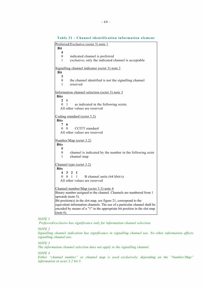
- 69 -
Table 31 - Channel identi f icat ion information element
Preferred/Exclusive (octet 3) note 1 Bit 4 0 indicated channel is preferred 1 exclusive; only the indicated channel is acceptable
Signalling channel indicator (octet 3) note 2
Bit 3 0 the channel identified is not the signalling channel 1 reserved
Information channel selection (octet 3) note 3 Bits 2 1 0 1 as indicated in the following octets
All other values are reserved Coding standard (octet 3.2) Bits 7 6 0 0 CCITT standard
All other values are reserved Number/Map (octet 3.2) Bits 5 0 channel is indicated by the number in the following octet 1 channel map
Channel type (octet 3.2) Bits 4 3 2 1 0 0 1 1 B channel units (64 kbit/s)
All other values are reserved Channel number/Map (octet 3.3) note 4 Binary number assigned to the channel. Channels are numbered from 1 upwards (note 5). Bit position(s) in the slot map, see figure 21, correspond to the equivalent information channels. The use of a particular channel shall be encoded by means of a "1" in the appropriate bit position in the slot map (note 6).
NOTE 1 Preferred/exclusive has significance only for information channel selection.
NOTE 2 Signalling channel indication has significance in signalling channel use. No other information affects signalling channel use.
NOTE 3 The information channel selection does not apply to the signalling channel.
NOTE 4 Either “channel number” or channel map is used exclusively, depending on the “Number/Map” information in octet 3.2 bit 5.
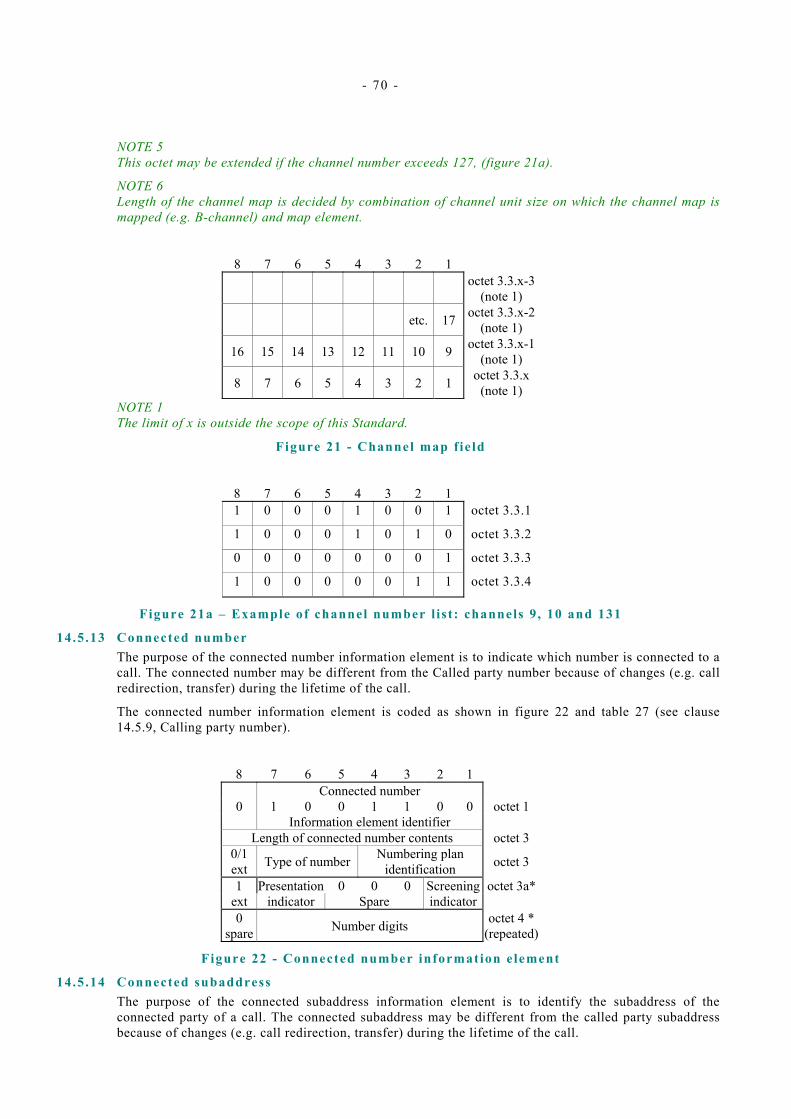
- 70 -
NOTE 5 This octet may be extended if the channel number exceeds 127, (figure 21a).
NOTE 6 Length of the channel map is decided by combination of channel unit size on which the channel map is mapped (e.g. B-channel) and map element.
8 7 6 5 4 3 2 1 octet 3.3.x-3
(note 1) etc. 17 octet 3.3.x-2
(note 1)
16 15 14 13 12 11 10 9 octet 3.3.x-1(note 1)
8 7 6 5 4 3 2 1 octet 3.3.x (note 1)
NOTE 1 The limit of x is outside the scope of this Standard.
Figure 21 - Channel map f ie ld
8 7 6 5 4 3 2 1 1 0 0 0 1 0 0 1 octet 3.3.1
1 0 0 0 1 0 1 0 octet 3.3.2
0 0 0 0 0 0 0 1 octet 3.3.3
1 0 0 0 0 0 1 1 octet 3.3.4
Figure 21a – Example of channel number l is t : channels 9 , 10 and 131
14.5 .13 Connected number The purpose of the connected number information element is to indicate which number is connected to a call. The connected number may be different from the Called party number because of changes (e.g. call redirection, transfer) during the lifetime of the call.
The connected number information element is coded as shown in figure 22 and table 27 (see clause 14.5.9, Calling party number).
8 7 6 5 4 3 2 1 Connected number
0 1 0 0 1 1 0 0 octet 1 Information element identifier
Length of connected number contents octet 3 0/1 ext Type of number Numbering plan
identification octet 3
1 Presentation 0 0 0 Screening octet 3a* ext indicator Spare indicator 0
spare Number digits octet 4 * (repeated)
Figure 22 - Connected number information element
14.5 .14 Connected subaddress The purpose of the connected subaddress information element is to identify the subaddress of the connected party of a call. The connected subaddress may be different from the called party subaddress because of changes (e.g. call redirection, transfer) during the lifetime of the call.
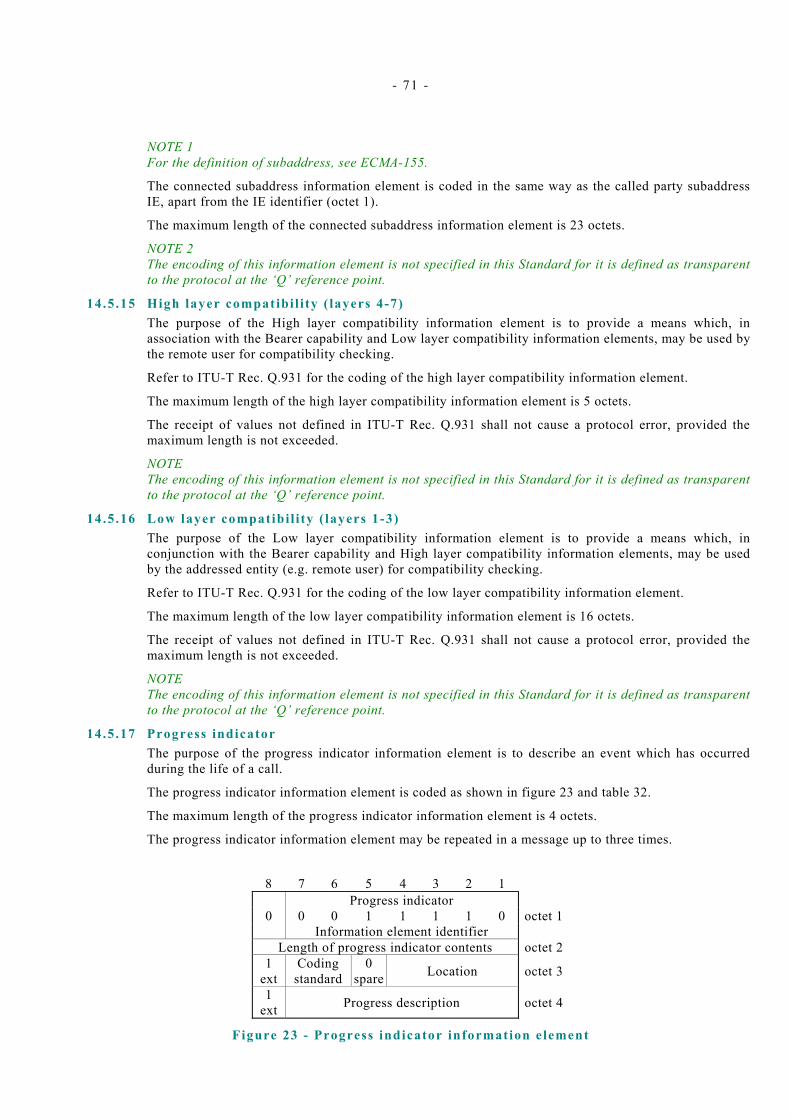
- 71 -
NOTE 1 For the definition of subaddress, see ECMA-155.
The connected subaddress information element is coded in the same way as the called party subaddress IE, apart from the IE identifier (octet 1).
The maximum length of the connected subaddress information element is 23 octets.
NOTE 2 The encoding of this information element is not specified in this Standard for it is defined as transparent to the protocol at the ‘Q’ reference point.
14.5 .15 High layer compatibi l i ty ( layers 4-7) The purpose of the High layer compatibility information element is to provide a means which, in association with the Bearer capability and Low layer compatibility information elements, may be used by the remote user for compatibility checking.
Refer to ITU-T Rec. Q.931 for the coding of the high layer compatibility information element.
The maximum length of the high layer compatibility information element is 5 octets.
The receipt of values not defined in ITU-T Rec. Q.931 shall not cause a protocol error, provided the maximum length is not exceeded.
NOTE The encoding of this information element is not specified in this Standard for it is defined as transparent to the protocol at the ‘Q’ reference point.
14.5 .16 Low layer compatibi l i ty ( layers 1-3) The purpose of the Low layer compatibility information element is to provide a means which, in conjunction with the Bearer capability and High layer compatibility information elements, may be used by the addressed entity (e.g. remote user) for compatibility checking.
Refer to ITU-T Rec. Q.931 for the coding of the low layer compatibility information element.
The maximum length of the low layer compatibility information element is 16 octets.
The receipt of values not defined in ITU-T Rec. Q.931 shall not cause a protocol error, provided the maximum length is not exceeded.
NOTE The encoding of this information element is not specified in this Standard for it is defined as transparent to the protocol at the ‘Q’ reference point.
14.5.17 Progress indicator The purpose of the progress indicator information element is to describe an event which has occurred during the life of a call.
The progress indicator information element is coded as shown in figure 23 and table 32.
The maximum length of the progress indicator information element is 4 octets.
The progress indicator information element may be repeated in a message up to three times.
8 7 6 5 4 3 2 1 Progress indicator
0 0 0 1 1 1 1 0 octet 1 Information element identifier
Length of progress indicator contents octet 2 1
ext Coding
standard 0
spare Location octet 3
1 ext Progress description octet 4
Figure 23 - Progress indicator information element

- 72 -
Table 32 - Progress indicator information element
Coding standard (octet 3) Bits 7 6 0 0 CCITT standardized coding as described below
All other values are reserved (note 5) Location (octet 3) Bits 4 3 2 1 0 0 0 0 User 0 0 0 1 Private network serving the local user 0 0 1 0 Public network serving the local user 0 0 1 1 Transit network 0 1 0 0 Public network serving the remote user 0 1 0 1 Private network serving the remote user 0 1 1 1 International network
1 0 1 0 Network beyond interworking point All other values are reserved
Progress description (octet 4) (note 5) Bits
5 4 3 2 1 No. 0 0 0 0 0 0 1 1
0 Destination address is non-ISDN (note 2)0 0 0 0 1 0 2 0 0 0 0 0 1 1 3 Origination address is non-ISDN (note 3)
0 0 0 0 1 0 0 4 Call has returned to the ISDN (note 4) 0 0 0 1 0 0 0 8 In-band information or appropriate
pattern now available All other values are reserved (note 5 )
7 6 Call is not end-to-end ISDN, further call
progress information may be available in-band (note 1)
NOTE 1 Progress description 1 indicates that interworking with a non-ISDN has occurred within the network or networks which the call has traversed.
NOTE 2 Progress description 2 indicates that the destination user equipment is non-ISDN equipment.
NOTE 3 Progress description 3 indicates that origination user equipment is non-ISDN equipment.
NOTE 4 Progress description 4 indicates that a call which has left the ISDN has returned at the same point it had left due to redirection within the non-ISDN.
NOTE 5 Additional progress descriptions are specified in annex ZB.
14.5 .18 Restart indicator The purpose of the restart indicator is to identify the entity to be restarted or which has been restarted.
The restart indicator information element is coded as shown in figure 24 and table 33.
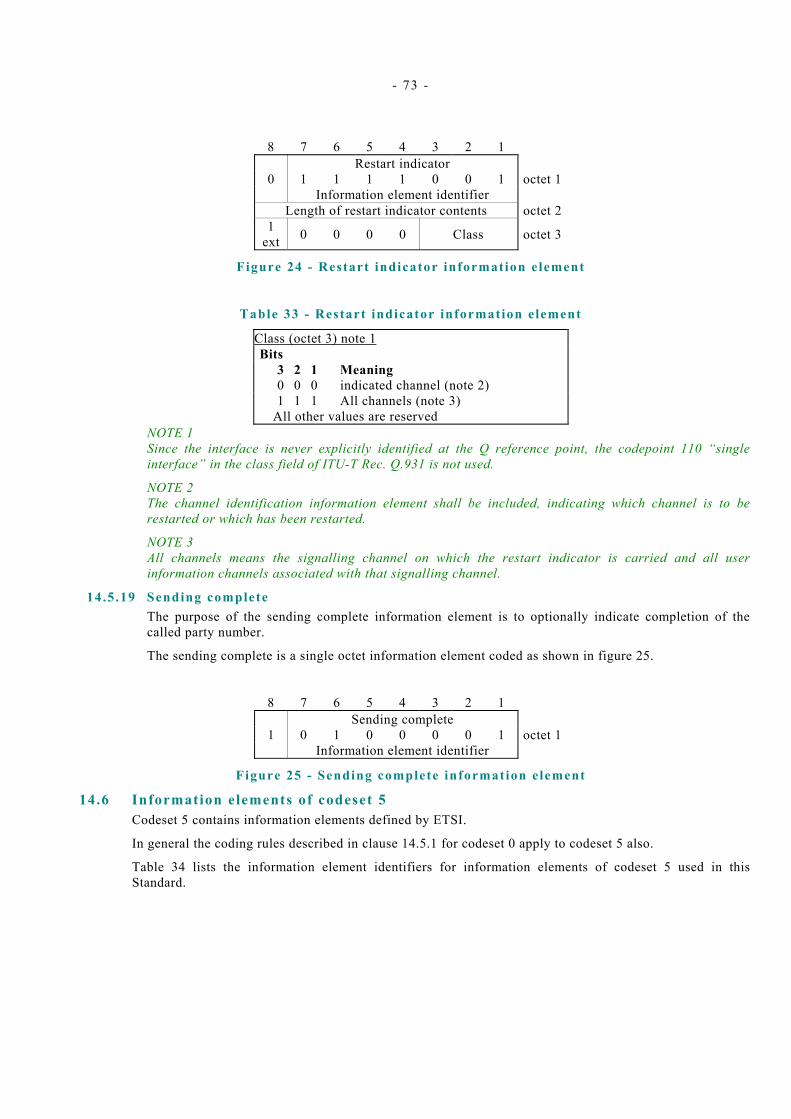
- 73 -
8 7 6 5 4 3 2 1 Restart indicator
0 1 1 1 1 0 0 1 octet 1 Information element identifier
Length of restart indicator contents octet 21
ext 0 0 0 0 Class octet 3
Figure 24 - Restart indicator information element
Table 33 - Restart indicator information element
Class (octet 3) note 1 Bits 3 2 1 Meaning 0 0 0 indicated channel (note 2) 1 1 1 All channels (note 3)
All other values are reserved NOTE 1 Since the interface is never explicitly identified at the Q reference point, the codepoint 110 “single interface” in the class field of ITU-T Rec. Q.931 is not used.
NOTE 2 The channel identification information element shall be included, indicating which channel is to be restarted or which has been restarted.
NOTE 3 All channels means the signalling channel on which the restart indicator is carried and all user information channels associated with that signalling channel.
14.5 .19 Sending complete The purpose of the sending complete information element is to optionally indicate completion of the called party number.
The sending complete is a single octet information element coded as shown in figure 25.
8 7 6 5 4 3 2 1 Sending complete
1 0 1 0 0 0 0 1 octet 1 Information element identifier
Figure 25 - Sending complete information element
14.6 Information elements of codeset 5 Codeset 5 contains information elements defined by ETSI.
In general the coding rules described in clause 14.5.1 for codeset 0 apply to codeset 5 also.
Table 34 lists the information element identifiers for information elements of codeset 5 used in this Standard.
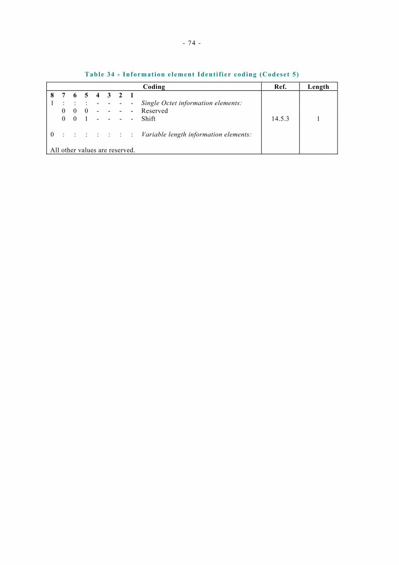
- 74 -
Table 34 - Information element Identi f ier coding (Codeset 5)
Coding Ref. Length 8 7 6 5 4 3 2 1 1 : : : - - - - Single Octet information elements: 0 0 0 - - - - Reserved
0 0 1 - - - Shift 1
0 : : : : : : : Variable length information elements:
All other values are reserved.
- 14.5.3
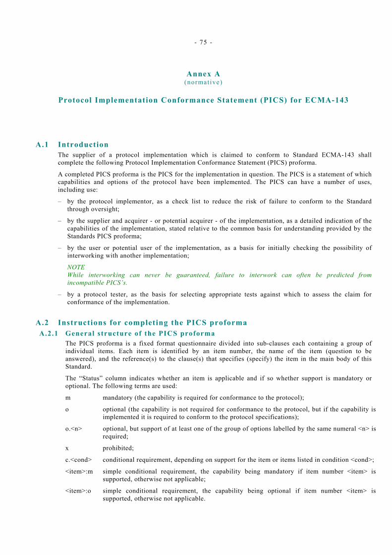
- 75 -
Annex A (normative)
Protocol Implementation Conformance Statement (PICS) for ECMA-143
c.<cond> conditional requirement, depending on support for the item or items listed in condition <cond>;
A.1 Introduction The supplier of a protocol implementation which is claimed to conform to Standard ECMA-143 shall complete the following Protocol Implementation Conformance Statement (PICS) proforma.
A completed PICS proforma is the PICS for the implementation in question. The PICS is a statement of which capabilities and options of the protocol have been implemented. The PICS can have a number of uses, including use:
– by the protocol implementor, as a check list to reduce the risk of failure to conform to the Standard through oversight;
– by the supplier and acquirer - or potential acquirer - of the implementation, as a detailed indication of the capabilities of the implementation, stated relative to the common basis for understanding provided by the Standards PICS proforma;
– by the user or potential user of the implementation, as a basis for initially checking the possibility of interworking with another implementation;
NOTE While interworking can never be guaranteed, failure to interwork can often be predicted from incompatible PICS’s.
– by a protocol tester, as the basis for selecting appropriate tests against which to assess the claim for conformance of the implementation.
A.2 Instructions for completing the PICS proforma A.2.1 General structure of the PICS proforma
The PICS proforma is a fixed format questionnaire divided into sub-clauses each containing a group of individual items. Each item is identified by an item number, the name of the item (question to be answered), and the reference(s) to the clause(s) that specifies (specify) the item in the main body of this Standard.
The “Status” column indicates whether an item is applicable and if so whether support is mandatory or optional. The following terms are used:
m mandatory (the capability is required for conformance to the protocol);
o optional (the capability is not required for conformance to the protocol, but if the capability is implemented it is required to conform to the protocol specifications);
o.<n> optional, but support of at least one of the group of options labelled by the same numeral <n> is required;
x prohibited;
<item>:m simple conditional requirement, the capability being mandatory if item number <item> is supported, otherwise not applicable;
<item>:o simple conditional requirement, the capability being optional if item number <item> is supported, otherwise not applicable.

- 76 -
Answers to the questionnaire items are to be provided either in the “Support” column, by simply marking an answer to indicate a restricted choice (Yes or No), or in the “Not Applicable” column (N/A).
A.2.2 Additional information Items of Additional Information allow a supplier to provide further information intended to assist the interpretation of the PICS. It is not intended or expected that a large quantity will be supplied, and a PICS can be considered complete without any such information. Examples might be an outline of the ways in which a (single) implementation can be set up to operate in a variety of environments and configurations.
References to items of Additional Information may be entered next to any answer in the questionnaire, and may be included in items of Exception information.
A.2.3 Exception information It may occasionally happen that a supplier will wish to answer an item with mandatory or prohibited status (after any conditions have been applied) in a way that conflicts with the indicated requirement. No pre-printed answer will be found in the Support column for this: instead, the supplier is required to write into the support column an x.<i> reference to an item of Exception Information, and to provide the appropriate rationale in the Exception item itself.
An implementation for which an Exception item is required in this way does not conform to ECMA-143.
NOTE A possible reason for the situation described above is that a defect in the Standard has been reported, a correction for which is expected to change the requirement not met by the implementation.
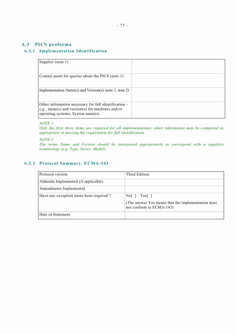
- 77 -
A.3 PICS proforma A.3.1 Implementation Identif ication
Supplier (note 1)
Contact point for queries about the PICS (note 1)
Implementation Name(s) and Version(s) (note 1, note 2)
Other information necessary for full identification - e.g., name(s) and version(s) for machines and/or operating systems; System name(s)
NOTE 1 Only the first three items are required for all implementations; other information may be completed as appropriate in meeting the requirement for full identification.
NOTE 2 The terms Name and Version should be interpreted appropriately to correspond with a suppliers terminology (e.g. Type, Series, Model).
A.3.2 Protocol Summary, ECMA-143 Protocol version Third Edition
Addenda Implemented (if applicable)
Amendments Implemented
Have any exception items been required ? No[ ] Yes[ ]
(The answer Yes means that the implementation does not conform to ECMA-143)
Date of Statement

- 78 -
A.3.3 Bearers Supported
ITEM QUESTION/FEATURE REFERENCE STATUS N/A SUPPORT
Z1 Support of the 64kbit/s Unrestricted Bearer 14.5.5 o.1 Yes[ ] No[ ]
Z2 Support of the 64kbit/s Bearer with Speech Transfer Capability
14.5.5 o.1 Yes[ ] No[ ]
Z3 Support of the 64kbit/s Bearer with 3.1kHz/Audio Transfer Capability
14.5.5 o.1 Yes[ ] No[ ]
Z4 Support of the Multi-rate Unrestricted Bearer 14.5.5 o.1 Yes[ ] No[ ]
Z5 Support of A-law User Information layer 1 protocol
14.5.5 (Z2 OR Z3):o.3
[ ] Yes[ ] No[ ]
Z6 Support of µ-law User Information layer 1 protocol
14.5.5 (Z2 OR Z3):o.3
[ ] Yes[ ] No[ ]
Z7 Support of the unrestricted digital information with tones / announcements bearer
14.5.5 o Yes[ ] No[ ]
A.3.4 General procedures A.3.4 .1 Use of the services of the Signal l ing Carriage Mechanism
ITEM QUESTION/FEATURE REFERENCE STATUS N/A SUPPORT
A1 Use of the services of the Signalling Carriage Mechanism
9.1 m Yes[ ]
A.3.4 .2 Handling of Protocol Error Condit ions
ITEM QUESTION/FEATURE REFERENCE STATUS N/A SUPPORT
A6 Treatment of protocol discriminator error 9.2.1 m Yes[ ]
A7 Treatment of message too short 9.2.2 m Yes[ ]
A8 Treatment of call reference error 9.2.3 m Yes[ ]
A9 Treatment of message type or message sequence errors 9.2.4 m Yes[ ]
A10 Treatment of information element errors 9.2.5 - 9.2.7 m Yes[ ]
A11 Signalling Carriage Mechanism reset 9.2.8 m Yes[ ]
Signalling Carriage Mechanism failure 9.2.9 m Yes[ ] A12
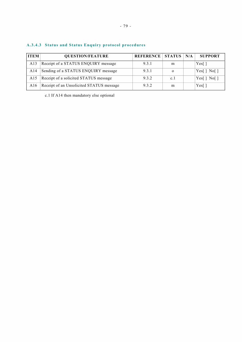
- 79 -
A.3.4 .3 Status and Status Enquiry protocol procedures
ITEM QUESTION/FEATURE REFERENCE STATUS N/A SUPPORT
A13 Receipt of a STATUS ENQUIRY message 9.3.1 m Yes[ ]
A14 Sending of a STATUS ENQUIRY message 9.3.1 o Yes[ ] No[ ]
A15 Receipt of a solicited STATUS message c.1 Yes[ ] No[ ] 9.3.2
9.3.2 m Yes[ ] A16 Receipt of an Unsolicited STATUS message
c.1 If A14 then mandatory else optional

- 80 -
A.3.5 Circuit Switched Call Control
ITEM QUESTION/FEATURE REFERENCE STATUS N/A SUPPORT
B1 Is the implementation capable of functioning as an Originating PINX ?
10.5 o.2 Yes[ ] No[ ]
B2 Is the implementation capable of functioning as an Incoming Gateway PINX ?
10.7 o.2 Yes[ ] No[ ]
B3 Is the implementation capable of functioning as a Transit PINX ?
10.4 o.2 Yes[ ] No[ ]
B4 Is the implementation capable of functioning as a Terminating PINX ?
10.6 o.2 Yes[ ] No[ ]
Is the implementation capable of functioning as an Outgoing Gateway PINX ?
10.8 o.2 Yes[ ] No[ ]
c.2 [ ] Yes[ ]
Does the implementation include a Sending Complete information element in every generated SETUP message ?
10.1.1 c.3 [ ] Yes[ ] No[ ]
B8 Information channel selection 10.1.2 m [ ] Yes[ ]
B9 Overlap Receiving procedures 10.1.3 c.4 (note 1)
[ ] Yes[ ] (note 1)
B10 Overlap Sending procedures 10.1.3 c.5 [ ] Yes[ ]
Call Proceeding - Enbloc Sending (Receipt and Origination)
10.1.4/ 10.1.4.1 [ ] Yes[ ]
B12 Receipt of Call Proceeding - Overlap Sending 10.1.4/ 10.1.4.2 B10:m [ ] Yes[ ]
B13 Sending of Call Proceeding - Overlap Receiving 10.1.4/ 10.1.4.2 B9:m [ ] Yes[ ]
Support of ALERTING origination 10.1.5 c.4 [ ]
B15 Support of ALERTING termination 10.1.5 c.2 [ ] Yes[ ]
B16 Support of call connection procedures 10.1.6 m (note 2) [ ] Yes[ ] (note 2)
B17 Sending of call progress information during call establishment
10.1.7 c.6 [ ] Yes[ ]
B18 Receipt of call progress information during call establishment
10.1.7 m Yes[ ]
B19 Support of call clearing procedures 10.2 m Yes[ ]
B20 Support of call collision procedures 10.3 m Yes[ ]
B5
B6 Support procedures for call request 10.1.1
B7
B11 m
B14 Yes[ ]
NOTE 1 If enbloc signalling only is used between two adjacent PINXs, overlap receiving procedures need not be tested.
NOTE 2 If by mutual agreement between adjacent PINXs T313 is not implemented, then the sending of CONNECT ACKNOWLEDGE message is optional.
c.2 If B1 OR B2 OR B3 then mandatory else N/A
c.3 If B1 OR B2 OR B3 then optional else N/A
c.4 If B3 OR B4 OR B5 then mandatory else N/A

- 81 -
c.5 If (B1 OR B2 OR B3) AND NOT B7 then mandatory else N/A
QUESTION/FEATURE REFERENCE STATUS N/A
c.6 If (B3 OR B4 OR B5) then optional else N/A
A.3.6 Call Control at a Transit PINX
ITEM SUPPORT
B3:m [ ] Yes[ ]
Call abort procedures 10.4.10.2 B3:o
C3 Call clearing procedures 10.4.10.1 B3:m [ ] Yes[ ]
C4 Handling of Category 1, 2 and 3 information elements at a Transit PINX
10.4.11 B3:m [ ] Yes[ ]
C1 Call origination/termination procedures 10.4/10.4.1 to 10.4.9
C2 Yes[ ] No[ ]
A.3.7 Call Control at a Originating PINX
ITEM QUESTION/FEATURE REFERENCE STATUS N/A SUPPORT
Call origination procedures [ ]
10.5.6 B1:m [ ] Yes[ ]
D1 10.5/10.5.1 to 10.5.5
B1:m Yes[ ]
D2 Call clearing procedures
A.3.8 Call Control at a Terminating PINX
ITEM QUESTION/FEATURE REFERENCE STATUS N/A SUPPORT
E1 Call termination procedures 10.6/10.6.1 to 10.6.4
B4:m [ ] Yes[ ]
E2 Call clearing procedures 10.6.5 B4:m [ ] Yes[ ]
A.3.9 Call Control at an Incoming Gateway PINX
ITEM QUESTION/FEATURE N/A REFERENCE STATUS SUPPORT
F1 Establishment of calls from another network 10.7/10.7.1 to 10.7.6
B2:m [ ] Yes[ ]
F2 Call clearing procedures 10.7.7 B2:m [ ] Yes[ ]
A.3.10 Call Control at an Outgoing Gateway PINX
ITEM QUESTION/FEATURE REFERENCE STATUS N/A SUPPORT
G1 Establishment of calls to another network 10.8/10.8.1 to 10.8.5
B5:m [ ] Yes[ ]
B5:m G2 Call clearing procedures 10.8.6 [ ] Yes[ ]
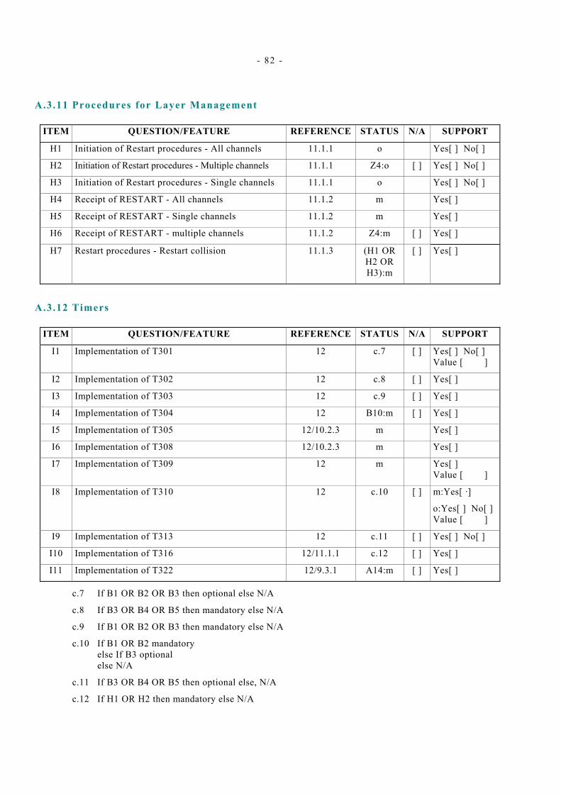
- 82 -
A.3.11 Procedures for Layer Management
ITEM QUESTION/FEATURE REFERENCE STATUS N/A SUPPORT
Initiation of Restart procedures - All channels 11.1.1 o
H2 Initiation of Restart procedures - Multiple channels 11.1.1 Z4:o [ ] Yes[ ] No[ ]
H3 Initiation of Restart procedures - Single channels 11.1.1 o Yes[ ] No[ ]
H4 Receipt of RESTART - All channels 11.1.2 m Yes[ ]
H5 Receipt of RESTART - Single channels 11.1.2 m Yes[ ]
Receipt of RESTART - multiple channels 11.1.2 Z4:m [ ]
H7 Restart procedures - Restart collision 11.1.3 (H1 OR H2 OR H3):m
[ ] Yes[ ]
H1 Yes[ ] No[ ]
H6 Yes[ ]
A.3.12 Timers
ITEM QUESTION/FEATURE REFERENCE STATUS N/A SUPPORT
I1 Implementation of T301 12 c.7 [ ] Yes[ ] No[ ] Value [ ]
c.8 [ ]
I3 Implementation of T303 12 c.9 [ ] Yes[ ]
I4 Implementation of T304 12 B10:m [ ] Yes[ ]
I5 Implementation of T305 12/10.2.3 m Yes[ ]
Implementation of T308 12/10.2.3 m Yes[ ]
I7 Implementation of T309 12 m Yes[ ] Value [ ]
I8 Implementation of T310 12 c.10 [ ] m:Yes[ ·]
o:Yes[ ] No[ ] Value [ ]
I9 Implementation of T313 12 c.11 [ ] Yes[ ] No[ ]
I10 Implementation of T316 12/11.1.1 c.12 [ ] Yes[ ]
I11 Implementation of T322 12/9.3.1 A14:m [ ] Yes[ ]
I2 Implementation of T302 12 Yes[ ]
I6
c.7 If B1 OR B2 OR B3 then optional else N/A
c.8 If B3 OR B4 OR B5 then mandatory else N/A
c.9 If B1 OR B2 OR B3 then mandatory else N/A
c.10 If B1 OR B2 mandatory else If B3 optional else N/A
c.11 If B3 OR B4 OR B5 then optional else, N/A
c.12 If H1 OR H2 then mandatory else N/A
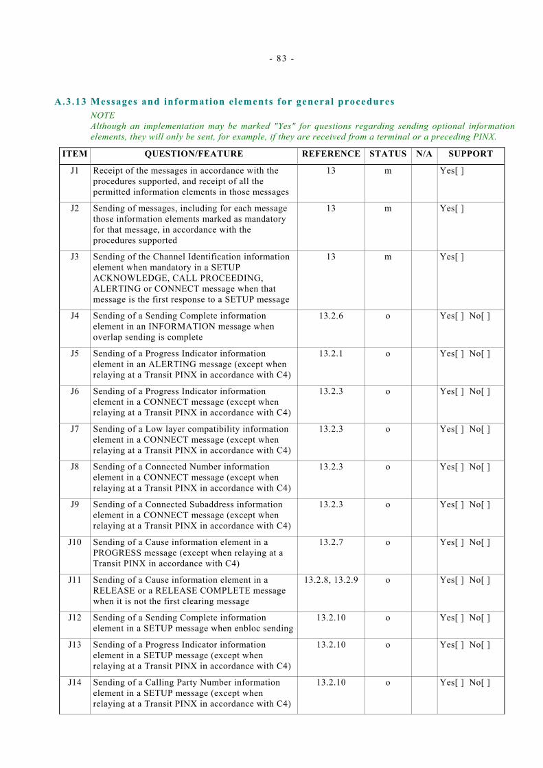
- 83 -
A.3.13 Messages and information elements for general procedures NOTE Although an implementation may be marked "Yes" for questions regarding sending optional information elements, they will only be sent, for example, if they are received from a terminal or a preceding PINX.
ITEM QUESTION/FEATURE REFERENCE STATUS N/A SUPPORT
Receipt of the messages in accordance with the procedures supported, and receipt of all the permitted information elements in those messages
13 Yes[ ]
J2 Sending of messages, including for each message those information elements marked as mandatory for that message, in accordance with the procedures supported
13 m Yes[ ]
J3 Sending of the Channel Identification information element when mandatory in a SETUP ACKNOWLEDGE, CALL PROCEEDING, ALERTING or CONNECT message when that message is the first response to a SETUP message
13 m Yes[ ]
Sending of a Sending Complete information element in an INFORMATION message when overlap sending is complete
13.2.6 o Yes[ ] No[ ]
J5 Sending of a Progress Indicator information element in an ALERTING message (except when relaying at a Transit PINX in accordance with C4)
13.2.1 o Yes[ ] No[ ]
J6 Sending of a Progress Indicator information element in a CONNECT message (except when relaying at a Transit PINX in accordance with C4)
13.2.3 o Yes[ ] No[ ]
J7 Sending of a Low layer compatibility information element in a CONNECT message (except when relaying at a Transit PINX in accordance with C4)
13.2.3 o Yes[ ] No[ ]
J8 Sending of a Connected Number information element in a CONNECT message (except when relaying at a Transit PINX in accordance with C4)
13.2.3 o Yes[ ] No[ ]
J9 Sending of a Connected Subaddress information element in a CONNECT message (except when relaying at a Transit PINX in accordance with C4)
13.2.3 o Yes[ ] No[ ]
J10 Sending of a Cause information element in a PROGRESS message (except when relaying at a Transit PINX in accordance with C4)
13.2.7 o Yes[ ] No[ ]
J11 Sending of a Cause information element in a RELEASE or a RELEASE COMPLETE message when it is not the first clearing message
13.2.8, 13.2.9 o Yes[ ] No[ ]
Sending of a Sending Complete information element in a SETUP message when enbloc sending
Yes[ ] No[ ]
J13 Sending of a Progress Indicator information element in a SETUP message (except when relaying at a Transit PINX in accordance with C4)
13.2.10 o Yes[ ] No[ ]
J14 Sending of a Calling Party Number information element in a SETUP message (except when relaying at a Transit PINX in accordance with C4)
13.2.10 o Yes[ ] No[ ]
J1 m
J4
J12 13.2.10 o

- 84 -
J15 Sending of a Calling Party Subaddress information element in a SETUP message (except when relaying at a Transit PINX in accordance with C4)
13.2.11 o Yes[ ] No[ ]
J16 Sending of a Called Party Subaddress information element in a SETUP message (except when relaying at a Transit PINX in accordance with C4)
13.2.11 o Yes[ ] No[ ]
J17 Sending of a Low Layer Compatibility information element in a SETUP message (except when relaying at a Transit PINX in accordance with C4)
13.2.10 o Yes[ ] No[ ]
J18 Sending of a High Layer Compatibility information element in a SETUP message (except when relaying at a Transit PINX in accordance with C4)
13.2.10 o Yes[ ] No[ ]
J19 Sending of a Channel Identification information element in a RESTART message
13.3.1 H2:m [ ] Yes[ ]
J20 Sending of a Channel Identification information element in a RESTART ACKNOWLEDGE message
13.3.2 o Yes[ ] No[ ]
J21 Support of channel map 14.5.12 o Yes[ ] No[ ]
J22 Type of number supported for ISDN/Telephony Numbering Plan:
14.5.7 o
Yes[ ] No[ ] International number Yes[ ] No[ ] National number Yes[ ] No[ ]
Subscriber number
J23 Type of number supported for Private Numbering Plan:
14.5.7 o
Unknown Yes[ ] No[ ] Level 2 regional number Yes[ ] No[ ] Level 1 regional number Yes[ ] No[ ] PISN specific number Yes[ ] No[ ] Level 0 regional number Yes[ ] No[ ] Abbreviated number Yes[ ] No[ ]
Type of number supported for Unknown Numbering Plan:
14.5.7 o
Unknown Yes[ ] No[ ]
J25 Message formats and codings for messages and information elements supported
14 m Yes[ ]
Unknown
Yes[ ] No[ ]
J24
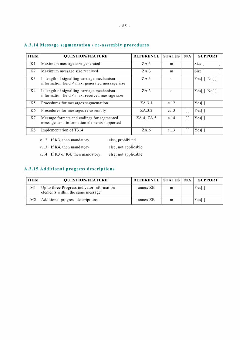
- 85 -
A.3.14 Message segmentation / re-assembly procedures
ITEM QUESTION/FEATURE
REFERENCE STATUS N/A SUPPORT
K1 Maximum message size generated ZA.3 m Size [ ]
K2 Maximum message size received ZA.3 m Size [ ]
K3 Is length of signalling carriage mechanism information field < max. generated message size
ZA.3 o Yes[ ] No[ ]
K4 Is length of signalling carriage mechanism information field < max. received message size
ZA.3 o Yes[ ] No[ ]
K5 Procedures for messages segmentation ZA.3.1 c.12 Yes[ ]
K6 Procedures for messages re-assembly ZA.3.2 c.13 [ ] Yes[ ]
K7 Message formats and codings for segmented messages and information elements supported
ZA.4, ZA.5 c.14 [ ] Yes[ ]
[ ] Yes[ ] K8 Implementation of T314 ZA.6 c.13
c.12 If K3, then mandatory else, prohibited
c.13 If K4, then mandatory else, not applicable
c.14 If K3 or K4, then mandatory else, not applicable
A.3.15 Additional progress descriptions
ITEM QUESTION/FEATURE
REFERENCE STATUS N/A SUPPORT
M1 Up to three Progress indicator information elements within the same message
annex ZB m Yes[ ]
M2 Additional progress descriptions annex ZB m Yes[ ]

- 86 -
- 87 -
Annex B ( informative)
Use of the cause information element
B.1 Definition of cause values Cause Number 1 “Unallocated (unassigned) number” This cause indicates that the destination requested by the calling user cannot be reached because, although the number is in a valid format, it is not currently assigned (allocated).
Cause Number 3 “No route to destination” This cause indicates that the called user cannot be reached because the network through which the call has been routed does not serve the desired destination.
Cause Number 6 “Channel unacceptable” This cause indicates that the channel most recently identified is not acceptable to the sending entity for use in this call.
Cause Number 16 “Normal call clearing” This cause indicates that one of the users involved in the call has requested that the call be cleared.
Cause Number 17 “User busy” This cause is used when the user equipment is compatible with the call but called user resources are temporarily unavailable.
Cause Number 18 “No user responding” This cause is used when the called user’s equipment does not respond to a call establishment message with either an alerting or a connect indication within the prescribed period of time allocated.
Cause Number 19 “No answer from user (user alerted)” This cause is used when a user has provided an alerting indication but has not provided a connect indication within a prescribed period of time.
Cause Number 21 “Call rejected” This cause indicates that the called user does not wish to accept this call, although his equipment is neither busy nor incompatible.
Cause Number 22 “Number changed” This cause is returned to a calling user when the called party number indicated by the calling user is no longer assigned. The new called party number may optionally be included in the diagnostic field.(If a network does not support this capability, cause number 1 "Unallocated (unassigned) number" shall be used).
Cause Number 27 “Destination out of order” This cause indicates that the destination indicated by the user cannot be reached because the interface to the destination is not functioning correctly, i.e. a signalling message could not be delivered to the remote user (e.g., a Signalling Carriage Mechanism failure at the remote user, user equipment off-line, etc).
Cause Number 28 “Invalid number format (address incomplete)” This cause indicates that the called user cannot be reached because the called party number is not a valid format or is not complete.
Cause Number 30 “Response to STATUS ENQUIRY” This cause is included in the STATUS message when the reason for generating the STATUS message was the prior receipt of a STATUS ENQUIRY message.
Cause Number 31 “Normal unspecified” This cause is used to report a normal event only when no other cause in the normal class applies.
- 88 -
Cause Number 34 “No circuit/channel available” This cause indicates that there is no appropriate circuit /channel presently available to handle the call.
Cause Number 41 “Temporary failure” This cause indicates that the network is not functioning correctly and that the condition is not likely to last a long period of time. (The user may wish to try another call attempt almost immediately).
Cause Number 44 “Requested circuit/channel not available” This cause is returned when the circuit or channel indicated by the requesting entity cannot be provided by the other side of the interface/by the peer entity.
Cause Number 57 “Bearer capability not authorized” This cause indicates that the user has requested a bearer capability which is implemented by the equipment generating this cause but which the user is not authorized to use.
Cause Number 58 “Bearer capability not presently available” This cause indicates that the user has requested a bearer capability which is implemented by the equipment generating this cause but which is not available at this instant.
Cause Number 63 “Service or option not available, unspecified” This cause is used to report a service or option not available event only when no other cause in the service or option not available class applies.
Cause Number 65 “Bearer capability not implemented” This cause indicates that the equipment sending this cause does not support the bearer capability requested.
Cause Number 81 “Invalid call reference value” This cause indicates that the equipment sending this cause has received a message with a call reference which is not currently in use on that particular link.
Cause Number 82 “Identified channel does not exist” This cause indicates that the equipment sending this cause has received a request to use a channel not activated on the inter PINX link.
Cause Number 88 “Incompatible destination” This cause indicates that the equipment sending this cause has received a request to establish a call which has LLC, HLC, or other compatibility attributes (e.g. data rate) which cannot be accommodated.
Cause Number 96 “Mandatory information element is missing” This cause indicates that the equipment sending this cause has received a message which is missing an information element that must be present in order for that message to be processed.
Cause Number 97 “Message type non-existent or not implemented” This cause indicates that the equipment sending this cause has received a message with a message type it does not recognise either because this is a message not defined or defined but not implemented by the equipment sending this cause.
Cause Number 98 “Message not compatible with call state or message type non-existent or not implemented” This cause indicates that the equipment sending this cause has received a message which it does not recognise or which is not compatible with the call state.
Cause Number 99 “Information element non-existent or not implemented” This cause indicates that the equipment sending this cause has received a message which includes information elements not recognised because the information element identifier is not defined or it is defined but not implemented by the equipment sending the cause.
Cause Number 100 “Invalid information element contents” This cause indicates that the equipment sending this cause has received an information element which it has implemented; however, one or more of the fields in the information element are coded in a way that has not been implemented by the equipment sending this cause.
Cause Number 101 “Message not compatible with call state” This cause indicates that the equipment sending this cause has received a message which is incompatible with the call state, or a STATUS message indicating an incompatible call state.
- 89 -
Cause Number 102 “Recovery on timer expiry” This cause indicates that a procedure has been initiated by the expiry of a timer in association with the PSS1 error handling procedures.
Cause Number 111 “Protocol error, unspecified” This cause is used to report a protocol error event only when no other cause in the protocol error class applies.
B.2 Use of causes for busy conditions The following cause values are used in PSS1 for busy (= congestion) cases:
– cause number 34 “no circuit /channel available” should be generated by the side (incoming or outgoing) that determines that no suitable inter-PINX information channel is available to establish the call;
– cause number 44 “requested circuit /channel not available” should be generated by the incoming side if it is unable to accept the particular inter-PINX information channel proposed by the outgoing side.
In both cases the location field should be coded “PISN serving the local user”. This coding may be changed to “PISN serving the remote user” when received from another private network.
Note that cause number 17 “user busy” should not be generated when congestion is encountered at the Q-reference point.

- 90 -
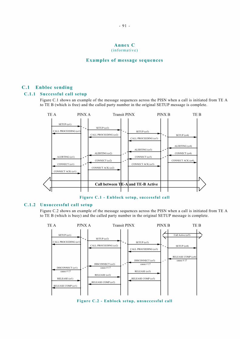
- 91 -
Annex C ( informative)
Examples of message sequences
C.1 Enbloc sending C.1.1 Successful call setup
Figure C.1 shows an example of the message sequences across the PISN when a call is initiated from TE A to TE B (which is free) and the called party number in the original SETUP message is complete.
SETUP (cr1)
CALL PROCEEDING (cr1)
ALERTING (cr1)
CONNECT ACK (cr1)
CONNECT (cr1)
TE A PINX A Transit PINX PINX B TE B
Call between TE-A and TE-B Active
SETUP (cr2)
CALL PROCEEDING (cr2)
ALERTING (cr2)
CONNECT ACK (cr2)
CONNECT (cr2)
SETUP (cr3)
CALL PROCEEDING (cr3)
ALERTING (cr3)
CONNECT ACK (cr3)
CONNECT (cr3)
SETUP (cr4)
ALERTING (cr4)
CONNECT ACK (cr4)
CONNECT (cr4)
Figure C.1 - Enblock setup, successful cal l
C.1.2 Unsuccessful call setup Figure C.2 shows an example of the message sequences across the PISN when a call is initiated from TE A to TE B (which is busy) and the called party number in the original SETUP message is complete.
SETUP (cr1)
CALL PROCEEDING (cr1)
DISCONNECT (cr1)
RELEASE COMP (cr1)
RELEASE (cr1)
TE A PTNX A Transit PINX PINX B TE B
SETUP (cr2)
CALL PROCEEDING (cr2)
DISCONNECT (cr2)
RELEASE COMP (cr2)
RELEASE (cr2)
SETUP (cr3)
CALL PROCEEDING (cr3)
DISCONNECT (cr3)
RELEASE COMP (cr3)
RELEASE (cr3)
SETUP (cr4)
RELEASE COMP (cr4)
cause # 17cause # 17
cause # 17cause # 17
Call Active (cr5)
Figure C.2 - Enblock setup, unsuccessful cal l
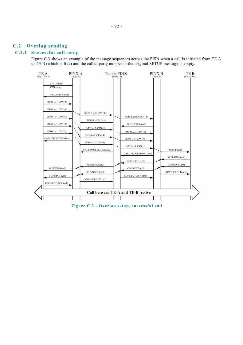
- 92 -
C.2 Overlap sending C.2.1 Successful call setup
Figure C.3 shows an example of the message sequences across the PISN when a call is initiated from TE A to TE B (which is free) and the called party number in the original SETUP message is empty.
CALL PROCEEDING (cr1)
ALERTING (cr1)
CONNECT ACK (cr1)
CONNECT (cr1)
TE A PINX A Transit PINX PINX B TE B
Call between TE-A and TE-B Active
CALL PROCEEDING (cr2)
ALERTING (cr2)
CONNECT ACK (cr2)
CONNECT (cr2)
ALERTING (cr3)
CONNECT ACK (cr3)
CONNECT (cr3)
SETUP (cr4)
ALERTING (cr4)
CONNECT ACK (cr4)
CONNECT (cr4)
(No. 12345) (No. 14345)(node 14)(node 13)(node 12)
SETUP (cr1)CPN empty
SETUP ACK (cr1)
INFO (cr1, CPN=1)
INFO (cr1, CPN=4)
INFO (cr1, CPN=3)
INFO (cr1, CPN=4)
INFO (cr1, CPN=5)
SETUP (cr2, CPN=14)
SETUP ACK (cr2)
INFO (cr2, CPN=5)
INFO (cr2, CPN=3)
INFO (cr2, CPN=4)
CALL PROCEEDING (cr3)
SETUP (cr3, CPN=14)
SETUP ACK (cr3)
INFO (cr3, CPN=5)
INFO (cr3, CPN=3)
INFO (cr3, CPN=4)
Figure C.3 - Overlap setup, successful cal l
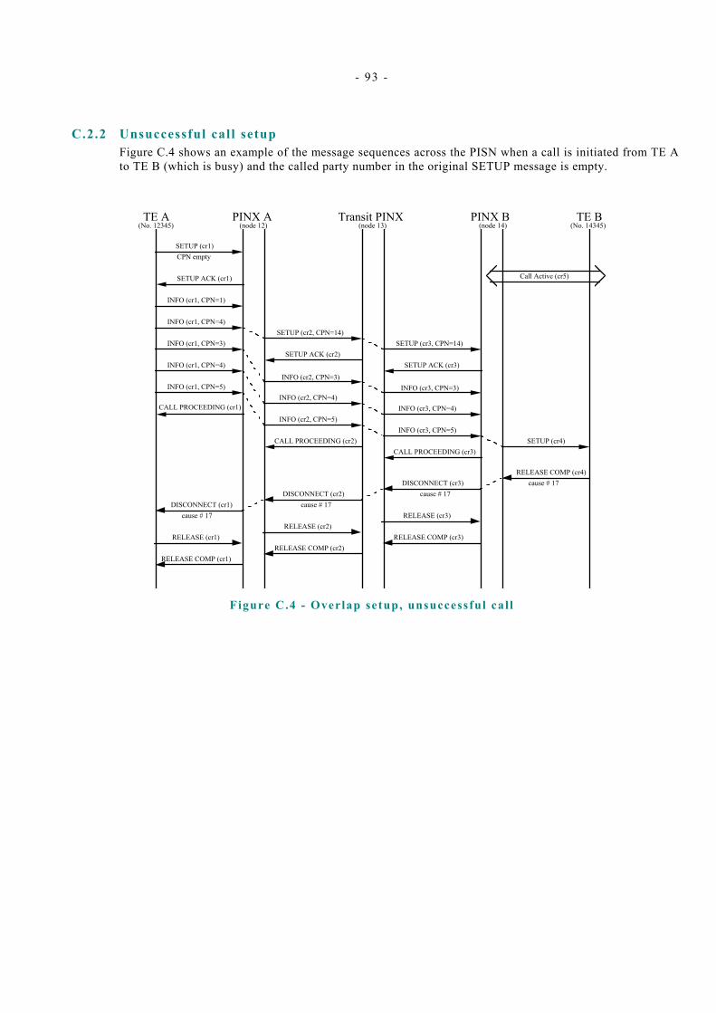
- 93 -
C.2.2 Unsuccessful call setup Figure C.4 shows an example of the message sequences across the PISN when a call is initiated from TE A to TE B (which is busy) and the called party number in the original SETUP message is empty.
CALL PROCEEDING (cr1)
TE A PINX A Transit PINX PINX B TE B
CALL PROCEEDING (cr2) SETUP (cr4)
(No. 12345) (No. 14345)(node 14)(node 13)(node 12)
SETUP (cr1)CPN empty
SETUP ACK (cr1)
INFO (cr1, CPN=1)
INFO (cr1, CPN=4)
INFO (cr1, CPN=3)
INFO (cr1, CPN=4)
INFO (cr1, CPN=5)
SETUP (cr2, CPN=14)
SETUP ACK (cr2)
INFO (cr2, CPN=5)
INFO (cr2, CPN=3)
INFO (cr2, CPN=4)
CALL PROCEEDING (cr3)
SETUP (cr3, CPN=14)
SETUP ACK (cr3)
INFO (cr3, CPN=5)
INFO (cr3, CPN=3)
INFO (cr3, CPN=4)
DISCONNECT (cr1)
RELEASE COMP (cr1)
RELEASE (cr1)
DISCONNECT (cr2)
RELEASE COMP (cr2)
RELEASE (cr2)
DISCONNECT (cr3)
RELEASE COMP (cr3)
RELEASE (cr3)
RELEASE COMP (cr4)
cause # 17cause # 17
cause # 17cause # 17
Call Active (cr5)
Figure C.4 - Overlap setup, unsuccessful cal l
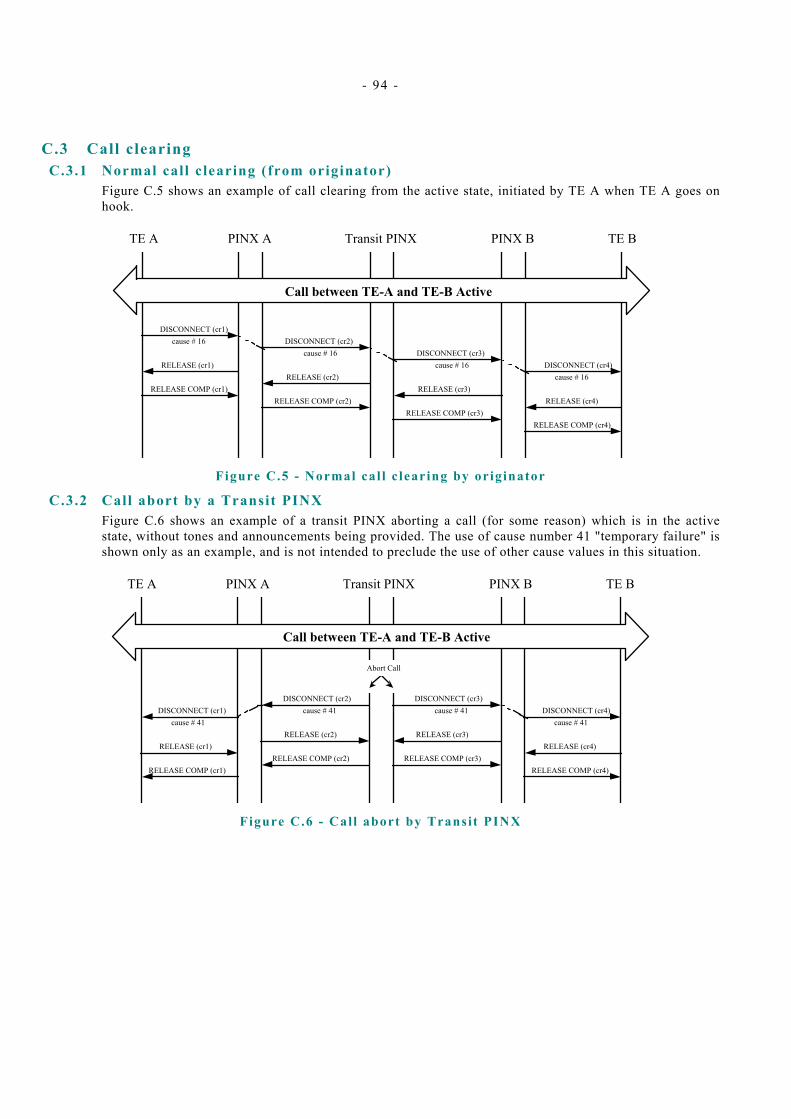
- 94 -
C.3 Call clearing C.3.1 Normal call clearing (from originator)
Figure C.5 shows an example of call clearing from the active state, initiated by TE A when TE A goes on hook.
TE A PINX A Transit PINX PINX B TE B
DISCONNECT (cr1)
RELEASE COMP (cr1)
RELEASE (cr1)
DISCONNECT (cr2)
RELEASE COMP (cr2)
RELEASE (cr2)
DISCONNECT (cr3)
RELEASE COMP (cr3)
RELEASE (cr3)
cause # 16cause # 16
cause # 16
Call between TE-A and TE-B Active
DISCONNECT (cr4)
RELEASE COMP (cr4)
RELEASE (cr4)
cause # 16
Figure C.5 - Normal cal l c learing by originator
C.3.2 Call abort by a Transit PINX Figure C.6 shows an example of a transit PINX aborting a call (for some reason) which is in the active state, without tones and announcements being provided. The use of cause number 41 "temporary failure" is shown only as an example, and is not intended to preclude the use of other cause values in this situation.
TE A PINX A Transit PINX PINX B TE B
DISCONNECT (cr1)
RELEASE COMP (cr1)
RELEASE (cr1)
DISCONNECT (cr2)
RELEASE COMP (cr2)
RELEASE (cr2)
DISCONNECT (cr3)
RELEASE COMP (cr3)
RELEASE (cr3)cause # 41
cause # 41 cause # 41
Call between TE-A and TE-B Active
DISCONNECT (cr4)
RELEASE COMP (cr4)
RELEASE (cr4)
cause # 41
Abort Call
Figure C.6 - Call abort by Transit PINX
- 95 -
Annex D ( informative)
Manufacturer specific information
PSS1 permits the inclusion in messages of non-standardised information which is specific to a particular design of PINX, a particular network, etc. This information is known as Manufacturer Specific Information.
This Standard also permits the use of non-standardised messages and information elements between adjacent PINXs. No procedures are defined in this Standard for the handling of these messages and information elements at PINXs except the error procedures defined in clauses 9.2.4 and 9.2.7, which will apply in the event of an unrecognised message or information element being received by a PINX.
NOTE Ambiguity may arise when two implementations use the same message identifier or information element identifier for different purposes.

- 96 -
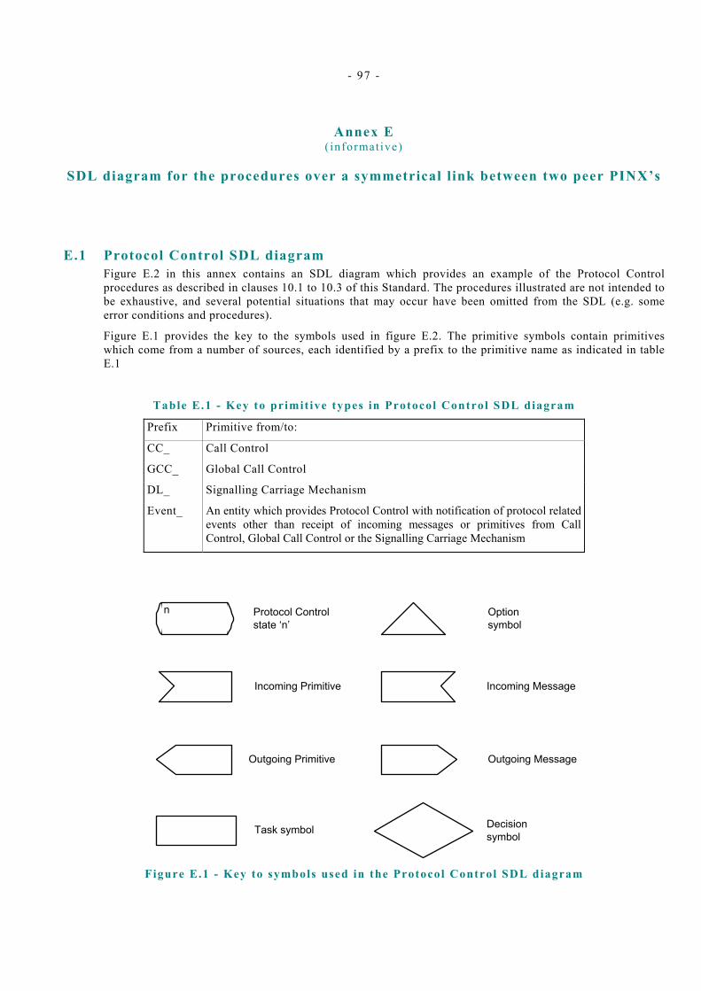
- 97 -
Annex E ( informative)
SDL diagram for the procedures over a symmetrical link between two peer PINX’s
E.1 Protocol Control SDL diagram Figure E.2 in this annex contains an SDL diagram which provides an example of the Protocol Control procedures as described in clauses 10.1 to 10.3 of this Standard. The procedures illustrated are not intended to be exhaustive, and several potential situations that may occur have been omitted from the SDL (e.g. some error conditions and procedures).
Figure E.1 provides the key to the symbols used in figure E.2. The primitive symbols contain primitives which come from a number of sources, each identified by a prefix to the primitive name as indicated in table E.1
Table E.1 - Key to primit ive types in Protocol Control SDL diagram
Prefix Primitive from/to:
CC_ Call Control
GCC_ Global Call Control
DL_ Signalling Carriage Mechanism
Event_ An entity which provides Protocol Control with notification of protocol related events other than receipt of incoming messages or primitives from Call Control, Global Call Control or the Signalling Carriage Mechanism
Protocol Control state ‘n’
n
Incoming Primitive
Decision symbol
Option symbol
Outgoing Primitive
Task symbol
Outgoing Message
Incoming Message
Figure E.1 - Key to symbols used in the Protocol Control SDL diagram
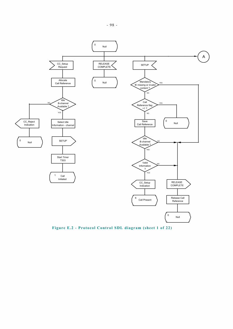
- 98 -
Allocate Call Reference
CC_Setup Request
Idle B-channel Available ?
NO
YES
Select Idle Information - channel
CC_Reject Indication
SETUP
Start Timer T303
1 Call Initiated
RELEASE COMPLETE
SETUP
Save Call Reference
Idle B-channel Available ?
NO
YES
NO
YES
Valid Information
?
Call Reference flag
=1 ?
NO
YES
CC_Setup Indication
RELEASE COMPLETE
Release Call Reference
6Call Present
0Null
A
Mandatory IE missing or invalid
content ?
NO
YES0
Null
0Null
0Null
0Null
Figure E.2 - Protocol Control SDL diagram (sheet 1 of 22)
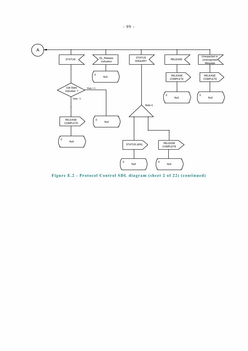
- 99 -
A
State = 0
STATUS
Call State Indicated ?
State ° 0
RELEASE COMPLETE
STATUS (#30) RELEASE COMPLETE
STATUS ENQUIRY
Note 4
RELEASE
RELEASE COMPLETE
Unexpected or unrecognised
Message
RELEASE COMPLETE
0Null
0Null
0Null
0Null
0Null
0Null
0Null
DL_Release Indication
Figure E.2 - Protocol Control SDL diagram (sheet 2 of 22) (continued)

- 100 -
1 Call Initiated
0 Null
Release B-channel and Call
Reference
CC_Reject Indication
RELEASE COMPLETE
Stop T303
CALL PROCEEDING
Stop T303
Start T310
CC_Proceed Indication
2 Overlap Sending
CC_More Info Indication
Start T304
Stop T303
SETUP ACK
CC_Release Request
RELEASE
Stop T303
Start T308
19 Release Request
Outgoing Call Proceeding
3
B
0 Null
Unexpected RELEASE
CC_Release Indication
RELEASE COMPLETE
Release Call reference
CC_Disconnect Request
DISCONNECT
Stop T303
Start T305
11 Disconnect Request
Figure E.2 - Protocol Control SDL diagram (sheet 3 of 22) (continued)

- 101 -
B
Stop T303
CONNECT
Stop T303
ALERTING
Note 3 Note 3
CC_Setup Confirmation
CC_Alerting Indication
4 Call Delivered
CONNECT ACKNOWLEDGE
10Call Active
CC_Proceed Indication
CC_Proceed Indication
1 Call Initiated
Restart T303
SETUP
First Expiry
?
YES
NO
RELEASE COMPLETE
Event_Expiry T303
0Null
Release Call reference
Note 1
CC_Release Indication
Unexpected DISCONNECT
Stop all timers
CC_Disconnect indication
12 Disconnect Indication
Optionally start T301
Figure E.2 - Protocol Control SDL diagram (sheet 4 of 22) (continued)
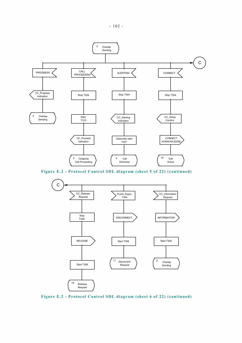
- 102 -
C
2 Overlap Sending
CALL PROCEEDING ALERTING CONNECT
Stop T304
CC_Setup Confirm
CONNECT ACKNOWLEDGE
10 Call Active
Stop T304
CC_Alerting Indication
4 Call Delivered
CC_Proceed Indication
Start T310
Outgoing Call Proceeding
3
Stop T304
2 Overlap Sending
CC_Progress Indication
PROGRESS
Optionally start T301
Figure E.2 - Protocol Control SDL diagram (sheet 5 of 22) (continued)
C
Event_Expiry T304
DISCONNECT
Start T305
11 Disconnect Request
CC_Information Request
INFORMATION
Start T304
2
Release Request
19
Start T308
CC_Release Request
RELEASE
Stop T304
Overlap Sending
Figure E.2 - Protocol Control SDL diagram (sheet 6 of 22) (continued)

- 103 -
Outgoing Call Proceeding
3
ALERTING PROGRESS
Stop T310
CC_Alerting Indication
CC_Progress Indication
4 Call Delivered
Outgoing Call Proceeding
3
10 Call Active
CONNECT ACKNOWLEDGE
CC_Setup Confirmation
Stop T310
CONNECT Event_expiry T310
DISCONNECT
Start T305
11 Disconnect Request
Stop T310
19 Release Request
RELEASE
CC_Release Request
Optionally start T301
Stop T310 (if CCITT Progress
Description No.s 1, 2 or 8 received)
Figure E.2 - Protocol Control SDL diagram (sheet 7 of 22) (continued)
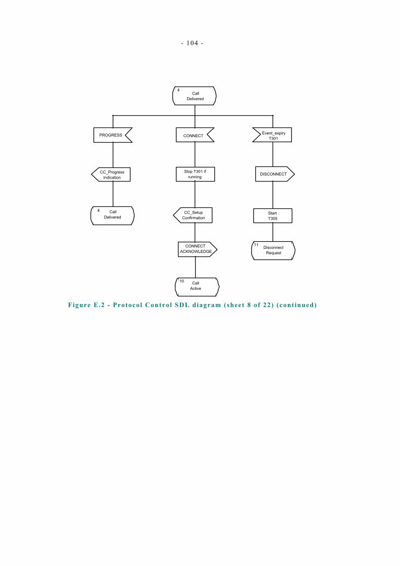
- 104 -
Call Delivered
4
10 Call Active
CONNECT ACKNOWLEDGE
CC_Setup Confirmation
Stop T301 if running
CONNECT Event_expiry T301
DISCONNECT
Start T305
11 Disconnect Request
CC_Progress Indication
4 Call Delivered
PROGRESS
Figure E.2 - Protocol Control SDL diagram (sheet 8 of 22) (continued)

- 105 -
6 Call Present
CC_Reject Request
CC_Proceed Request
CC_More Info Request
SETUP ACKNOWLEDGE
CALL PROCEEDING
Start T3029 Incoming
Call Proceeding
25 Overlap Receiving
0Null
Release Call Reference
RELEASE COMPLETE
CC_Setup Response
CC_Alerting Request
CONNECT
Start T313
ALERTING
7 Call Received
Connect Request
8
Note 3 Note 3
10Call Active
Figure E.2 - Protocol Control SDL diagram (sheet 9 of 22) (continued)

- 106 -
7 Call Received
CC_Progress Request
CC_Setup Response
PROGRESS CONNECT
7Call
Received Start T313
8Connect Request
11 Disconnect Request
Start T305
DISCONNECT
Event_Expiry T313
Stop T313
CONNECT ACK
8Connect Request
10Call
Active
10Call Active
Figure E.2 - Protocol Control SDL diagram (sheet 10 of 22) (continued)
10 Call Active
10 Call Active
CC_Progress Request
CONNECT ACKNOWLEDGE
PROGRESS
10 Call Active
10 Call Active
CC_Progress Indication
PROGRESS
States 7, 8 9 & 10
Remain in current state
INFORMATION
Discard Information
Figure E.2 - Protocol Control SDL diagram (sheet 11 of 22) (continued)

- 107 -
9Incoming
Call Proceeding
CC_Setup Response
CONNECT
CC_Alerting Request
CC_Progress Request
PROGRESSALERTING
7Call
receivedIncoming
Call proceeding
9Start T313
8 Connect Request
12 Disconnect Indication
RELEASE
CC_Release Indication
RELEASE COMPLETE
Release Call Reference
0Null
19 Release Request
Start T308
RELEASE
CC_Release Request
Release Information channel
Release Information channel
Figure E.2 - Protocol Control SDL diagram (sheet 12 of 22) (continued)
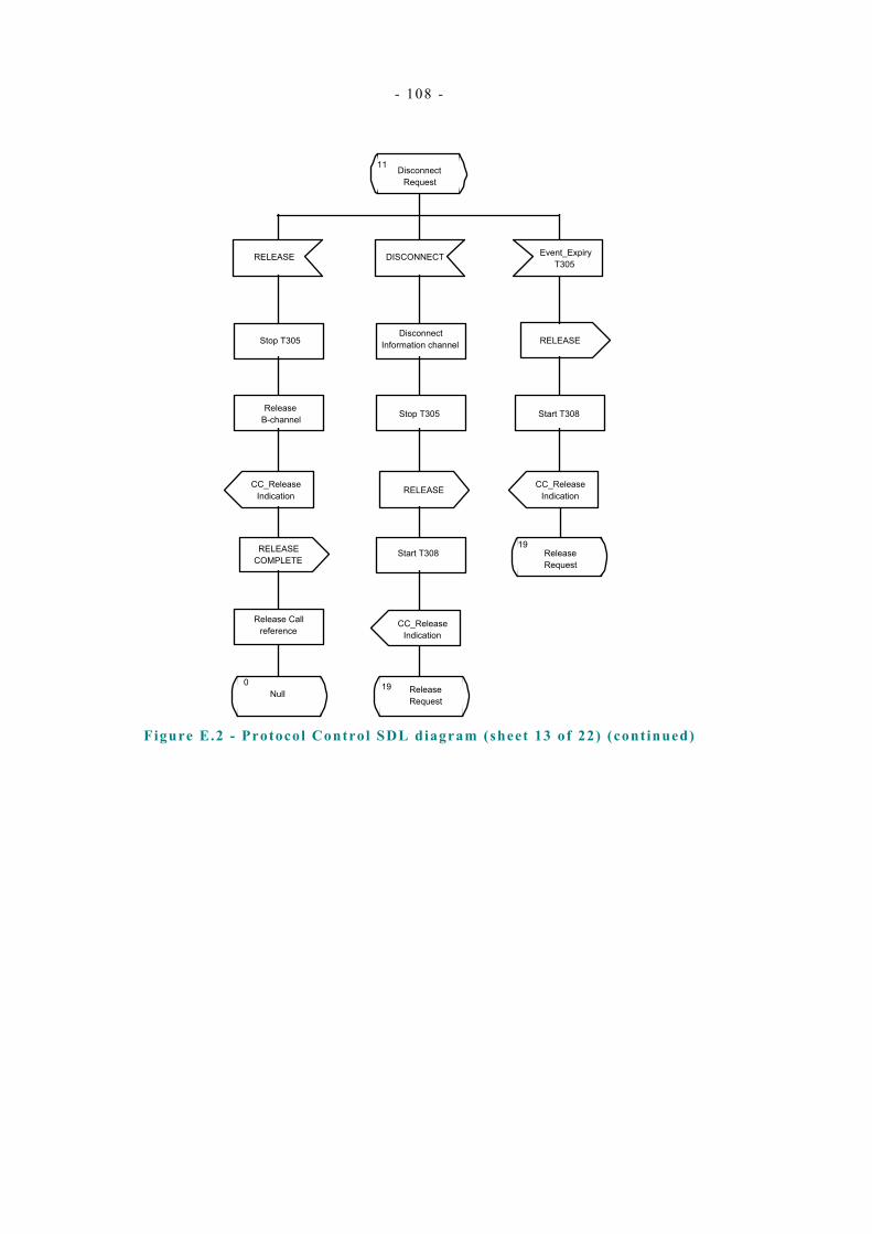
- 108 -
RELEASE
Stop T305
Release B-channel
CC_Release Indication
RELEASE COMPLETE
Release Call reference
0Null
11 Disconnect Request
DISCONNECT Event_Expiry T305
Disconnect Information channel
Stop T305
RELEASE
Start T308
RELEASE
Start T308
CC_Release Indication
19Release Request
19 Release Request
CC_Release Indication
Figure E.2 - Protocol Control SDL diagram (sheet 13 of 22) (continued)

- 109 -
19Release request
RELEASE RELEASE COMPLETE
Event_Expiry T308
Stop T308First
Timeout of T308
?
RELEASERelease Information channel
Release Call reference
0Null
Place Information channel in
maintenance condition
Restart T308
Release Call Reference
19Release Request
0Null
NO
YES
19Release request
STATUS (state °null)
Figure E.2 - Protocol Control SDL diagram (sheet 14 of 22) (continued)

- 110 -
Any state, excl: 0,1,6,11,12,19
CC_Disconnect Request
Disconnect Information channel
DISCONNECT
Start T305
11 Disconnect Request
Any state, excl: 0,1,11,12,19
RELEASE DISCONNECT
Disconect and release Information channel
Stop all related Timers
CC_Release Indication
Disconnect Information channel
CC_Disconnect Indication
12 Disconnect Indication
Stop all related Timers
Stop all related Timers
RELEASE COMPLETE
Release Call Reference
Null0
Figure E.2 - Protocol Control SDL diagram (sheet 15 of 22) (continued)

- 111 -
INFORMATION
CC_Information Indication
Start T302
25 Overlap Receiving
Incoming Call proceeding
9
CALL PROCEEDING
Stop T302
CC_Proceed Request
7Call
Received
ALERTING
Stop T302
CC_Alerting Request
8Connect Request
Start T313
CONNECT
Stop T302
CC_Setup Response
Event_Expiry T302
25 Overlap Receiving
Note 2
CC_Progress Request
PROGRESS
25Overlap
Receiving
CC_Timeout T302
25 Overlap Receiving
Figure E.2 - Protocol Control SDL diagram (sheet 16 of 22) (continued)

- 112 -
Any State (Except 0)
STATUS ENQUIRY
STATUS
Remain in current State
0Null State
Release Call reference
STATUS (state = 0)
Any State (except 0, 19)
STATUS (state ° 0)
Compatible State Indicated
?
YES
NO
RELEASE
Start T308
19 Release Request
Implementation Option
Note 5
Note 5
CC_Release Indication
CC_Release Indication
Figure E.2 - Protocol Control SDL diagram (sheet 17 of 22) (continued)
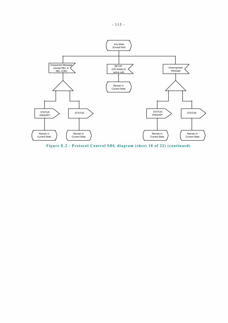
- 113 -
SETUP (CR relates to
active call)
Remain in Current State
STATUS
Remain in Current State
STATUS ENQUIRY
Unexpected Message (except REL or
REL COM)
STATUS ENQUIRY
STATUS
Remain in Current State
Any State (Except Null)
Unrecognised Message
Remain in Current State
Remain in Current State
Remain in Current State
Figure E.2 - Protocol Control SDL diagram (sheet 18 of 22) (continued)
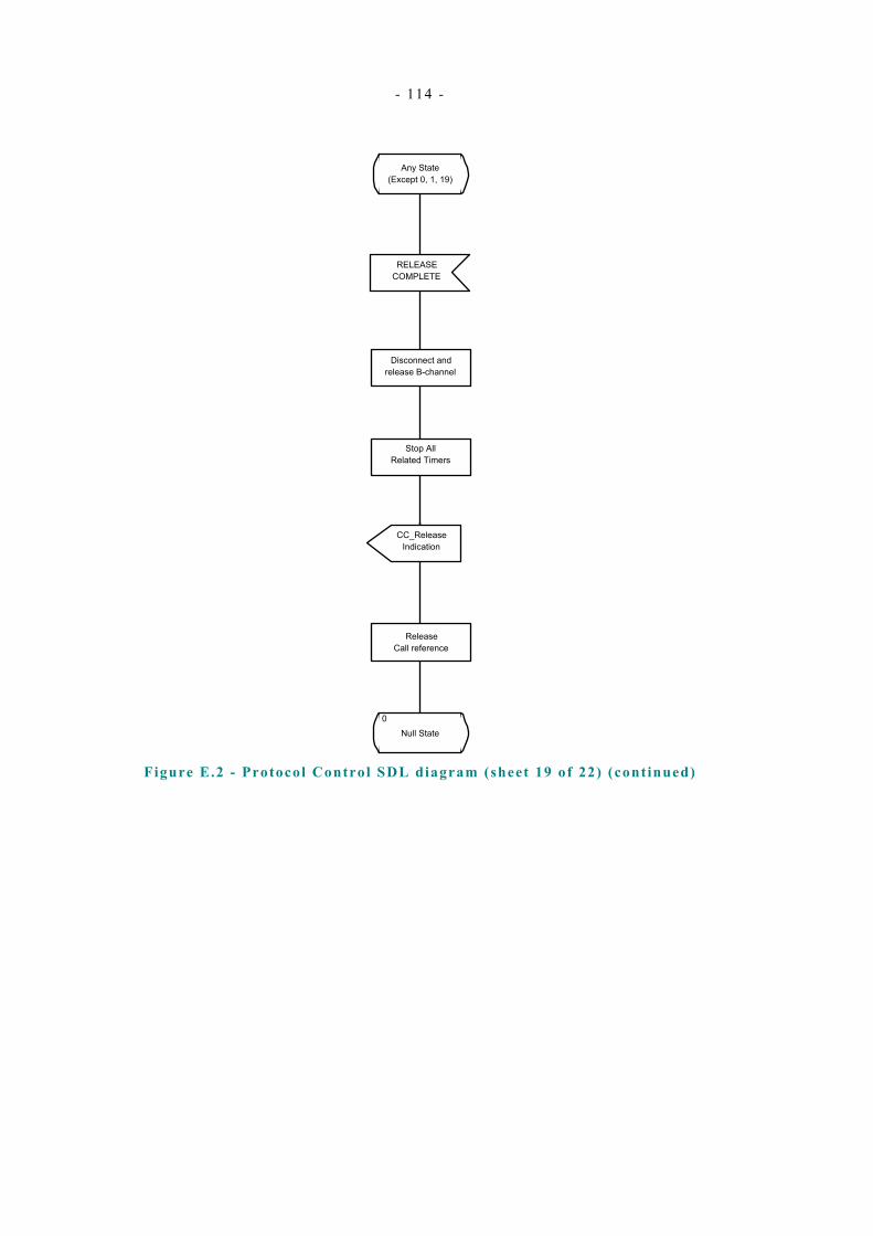
- 114 -
Any State (Except 0, 1, 19)
RELEASE COMPLETE
0Null State
Stop All Related Timers
Release Call reference
Disconnect and release B-channel
CC_Release Indication
Figure E.2 - Protocol Control SDL diagram (sheet 19 of 22) (continued)
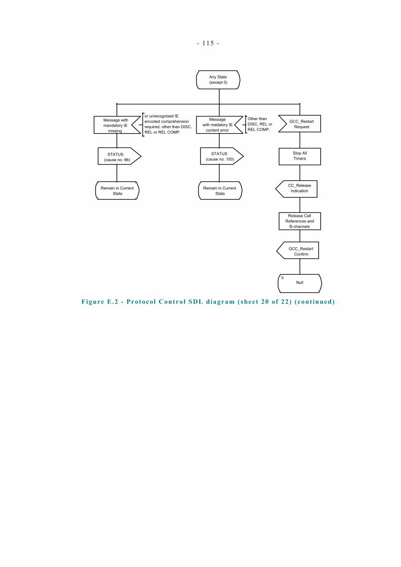
- 115 -
Message with mandatory IE
missing
Message with madatory IE
content error
STATUS (cause no. 96)
Remain in Current State
STATUS (cause no. 100)
Remain in Current State
Any State (except 0)
GCC_Restart Request
Stop All Timers
CC_Release Indication
Release Call References and
B-channels
GCC_Restart Confirm
0Null
or unrecognised IE encoded comprehension required, other than DISC, REL or REL COMP.
Other than DISC, REL or REL COMP.
Figure E.2 - Protocol Control SDL diagram (sheet 20 of 22) (continued)
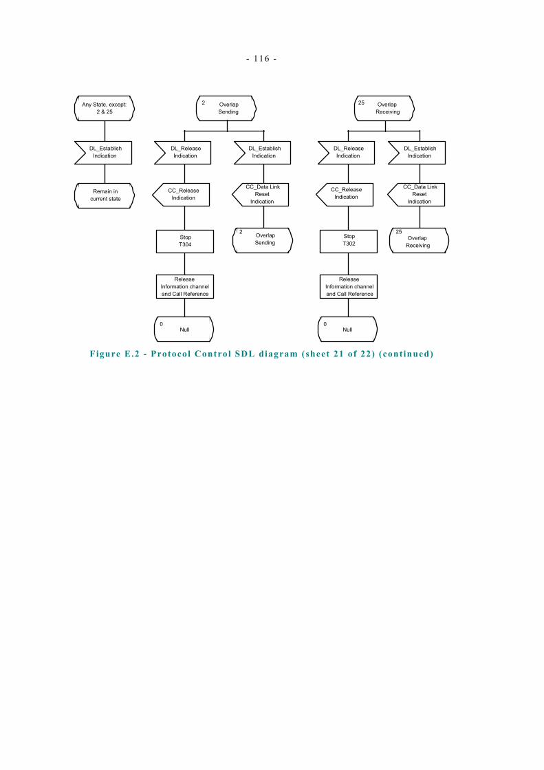
- 116 -
DL_Establish Indication
Any State, except: 2 & 25
DL_Establish Indication
CC_Data Link Reset
Indication
25 Overlap Receiving
DL_Establish Indication
2 Overlap Sending
2 Overlap Sending
CC_Data Link Reset
Indication
25Overlap
Receiving
Remain in current state
DL_Release Indication
DL_Release Indication
CC_Release Indication
0Null
Stop T302
CC_Release Indication
0Null
Stop T304
Release Information channel and Call Reference
Release Information channel and Call Reference
Figure E.2 - Protocol Control SDL diagram (sheet 21 of 22) (continued)
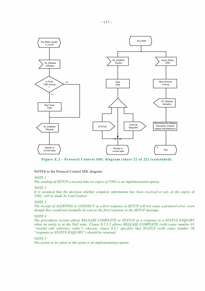
- 117 -
Any State, except: 0, 2 & 25
DL_Release Indication
NO
YESIs Timer T309 running
?
Start Timer T309
DL_Establish Request
Remain in Current state
Any State
Event_Expiry T309
DL_Establish Confirm
CC_Release Indication
Stop T309
0Null
STATUS ENQUIRYSTATUS
Remain in current state
Stop all timers running
Disconnect and release Information channel,
release Call Reference
Figure E.2 - Protocol Control SDL diagram (sheet 22 of 22) (concluded)
NOTES to the Protocol Control SDL diagram:
NOTE 1 The sending of SETUP a second time on expiry of T303 is an implementation option.
NOTE 2 It is assumed that the decision whether complete information has been received or not, at the expiry of T302, will be made by Call Control.
NOTE 3 The receipt of ALERTING or CONNECT as a first response to SETUP will not cause a protocol error, even though they would not normally be sent as the first response to the SETUP message.
NOTE 4 The procedures section allows RELEASE COMPLETE or STATUS as a response to a STATUS ENQUIRY when an entity is in the Null state. Clause 9.2.3.2 allows RELEASE COMPLETE (with cause number 81 “invalid call reference value”) whereas clause 9.3.1 specifies that STATUS (with cause number 30 “response to STATUS ENQUIRY”) should be returned.
NOTE 5 The action to be taken at this point is an implementation option.

- 118 -
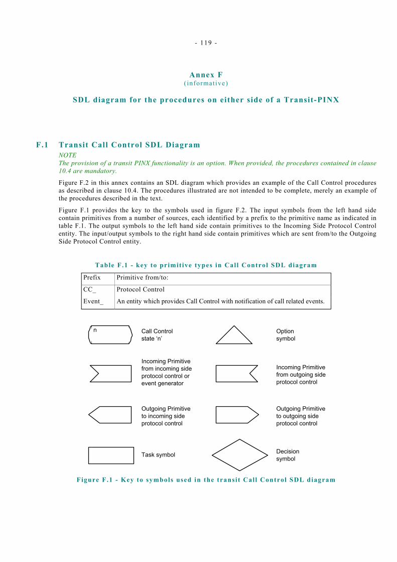
- 119 -
Annex F ( informative)
SDL diagram for the procedures on either side of a Transit-PINX
F.1 Transit Call Control SDL Diagram NOTE The provision of a transit PINX functionality is an option. When provided, the procedures contained in clause 10.4 are mandatory.
Figure F.2 in this annex contains an SDL diagram which provides an example of the Call Control procedures as described in clause 10.4. The procedures illustrated are not intended to be complete, merely an example of the procedures described in the text.
Figure F.1 provides the key to the symbols used in figure F.2. The input symbols from the left hand side contain primitives from a number of sources, each identified by a prefix to the primitive name as indicated in table F.1. The output symbols to the left hand side contain primitives to the Incoming Side Protocol Control entity. The input/output symbols to the right hand side contain primitives which are sent from/to the Outgoing Side Protocol Control entity.
Table F.1 - key to primit ive types in Cal l Control SDL diagram
Prefix Primitive from/to:
CC_ Protocol Control
Event_ An entity which provides Call Control with notification of call related events.
Call Control state ‘n’
n
Incoming Primitive from incoming side protocol control or event generator
Decision symbol
Option symbol
Outgoing Primitive to incoming side protocol control
Task symbol
Outgoing Primitive to outgoing side protocol control
Incoming Primitive from outgoing side protocol control
Figure F.1 - Key to symbols used in the transit Call Control SDL diagram
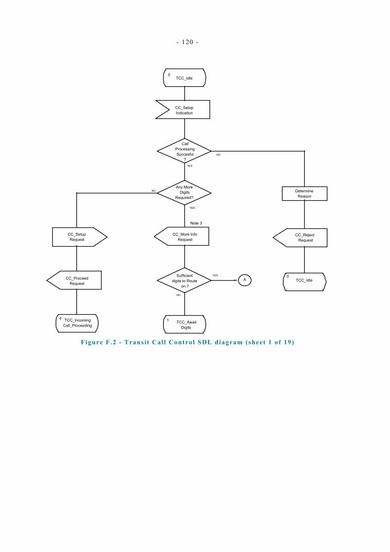
- 120 -
0TCC_Idle
Call Processing Succesful
?
Determine Reason
CC_Reject Request
CC_Setup Indication
NO
YES
NO
YES
Any More Digits
Required?
CC_More Info Request
0TCC_Idle
YESSufficient digits to Route
on ?
NO
CC_Setup Request
CC_Proceed Request
TCC_Incoming Call_Proceeding
4
A
Note 3
1 TCC_Await Digits
Figure F.2 - Transit Call Control SDL diagram (sheet 1 of 19)
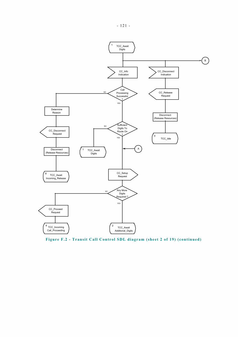
- 121 -
1 TCC_Await Digits
CC_Info Indication
Call Processing Successful
?
Determine Reason
CC_Disconnect Request
8 TCC_Await Incoming_Release
Sufficient Digits To Route On
?
1 TCC_Await Digits
NO
A
YES
CC_Setup Request
Any More Digits
Required ?
CC_Proceed Request
4 TCC_Incoming Call_Proceeding
2TCC_Await
Additional_Digits
CC_Disconnect Indication
Disconnect (Release Resources)
CC_Release Request
0TCC_Idle
YES
NO
YES
NO
Disconnect (Release Resources)
B
Figure F.2 - Transit Call Control SDL diagram (sheet 2 of 19) (continued)
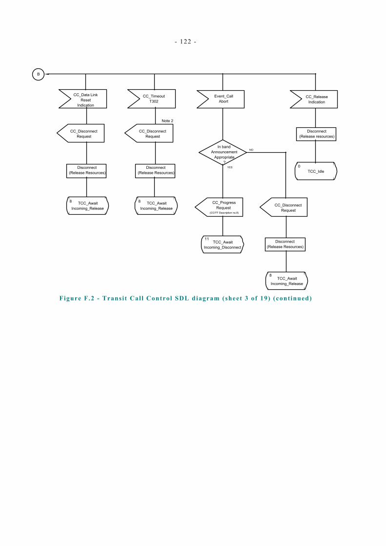
- 122 -
B
CC_Release Indication
Disconnect (Release resources)
0TCC_Idle
Event_Call Abort
CC_Disconnect Request
TCC_Await Incoming_Release
Disconnect (Release Resources)
CC_Progress Request
(CCITT Description no.8)
TCC_Await Incoming_Disconnect
NO
YES
In band Announcement
Appropriate ?
11
8
CC_Timeout T302
CC_Disconnect Request
Note 2
Disconnect (Release Resources)
TCC_Await Incoming_Release
8
CC_Data Link Reset
Indication
CC_Disconnect Request
Disconnect (Release Resources)
TCC_Await Incoming_Release
8
Figure F.2 - Transit Call Control SDL diagram (sheet 3 of 19) (continued)
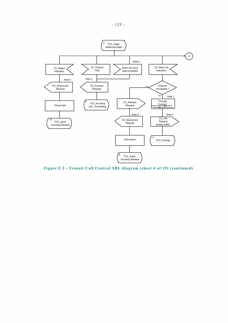
- 123 -
C
2 TCC_AwaitAdditional Digits
CC_RejectIndication
CC_DisconnectRequest
TCC_AwaitIncoming Release
CC_ProceedRequest
TCC_IncomingCall _Proceeding
Event_No moredigits accepted
CC_More infoIndication
ChannelAcceptable ?
CC_ReleaseRequest
ThroughConnect
3TCC_Overlap
Note 1
Note 2
Disconnect
TCC_AwaitIncoming Release
Disconnect
Note 2
YES
NO
CC_InfoRequest
(empty buffer)
Note 6
Note 2
8
4
8
CC_TimeoutT302
CC_DisconnectRequest
Note 9
Figure F.2 - Transit Call Control SDL diagram (sheet 4 of 19) (continued)
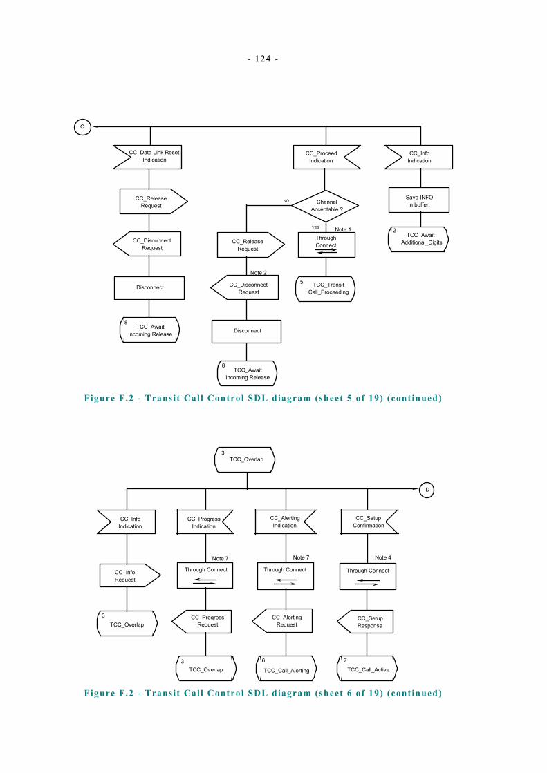
- 124 -
C
2TCC_Await
Additional_Digits
Channel Acceptable ?
NO
YES
Through ConnectCC_Release
Request
CC_Disconnect Request
8TCC_Await
Incoming Release
5 TCC_Transit Call_Proceeding
CC_Proceed Indication
CC_Info Indication
Save INFO in buffer.
Note 1
Disconnect
Note 2
CC_Release Request
CC_Disconnect Request
8TCC_Await
Incoming Release
Disconnect
CC_Data Link Reset Indication
Figure F.2 - Transit Call Control SDL diagram (sheet 5 of 19) (continued)
CC_Progress Indication
CC_Progress Request
Through Connect
Note 7
CC_Alerting Indication
CC_Alerting Request
TCC_Call_Alerting
6
Through Connect
Note 7
TCC_Overlap
CC_Info Indication
CC_Info Request
3
TCC_Overlap3
CC_Setup Confirmation
CC_Setup Response
TCC_Call_Active7
TCC_Overlap3
Through Connect
Note 4
D
Figure F.2 - Transit Call Control SDL diagram (sheet 6 of 19) (continued)
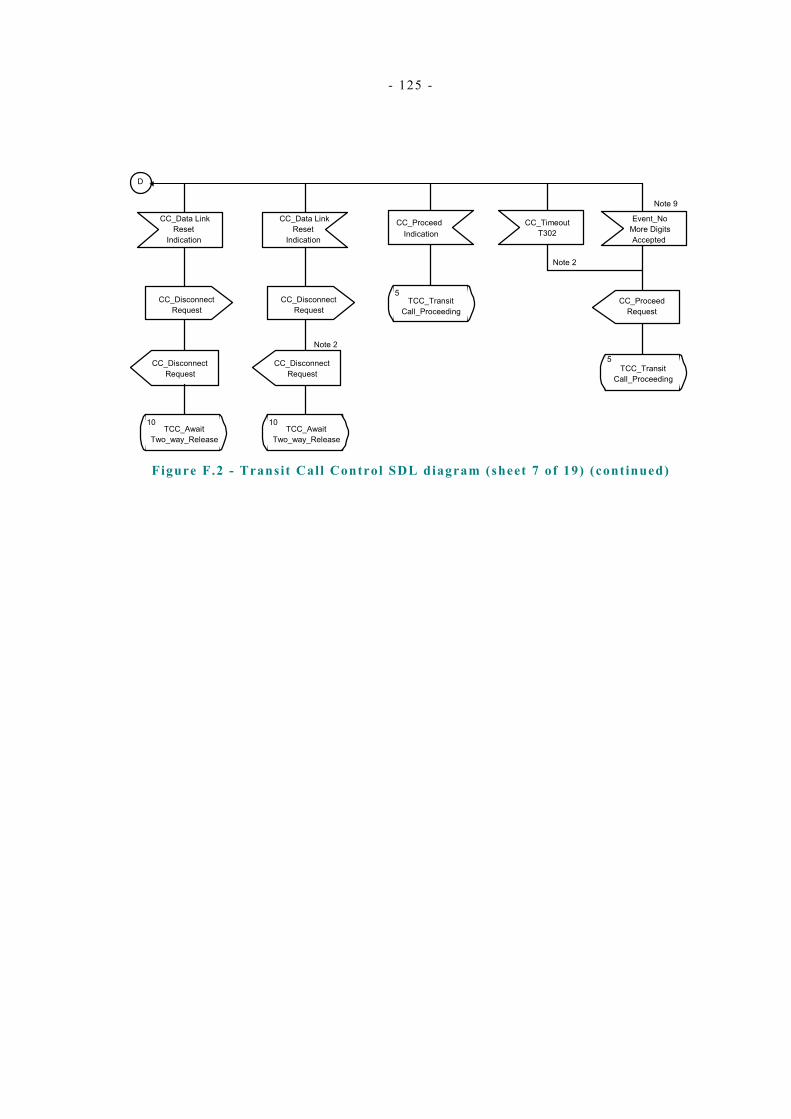
- 125 -
D
TCC_TransitCall_Proceeding
5CC_Proceed
Request
TCC_TransitCall_Proceeding
5
CC_TimeoutT302
Note 2
CC_DisconnectRequest
CC_DisconnectRequest
TCC_AwaitTwo_way_Release
10
CC_DisconnectRequest
Note 2
TCC_AwaitTwo_way_Release
10
IndicationCC_ProceedCC_Data Link
ResetIndication
CC_DisconnectRequest
More DigitsEvent_No
Accepted
CC_Data LinkReset
Indication
Note 9
Figure F.2 - Transit Call Control SDL diagram (sheet 7 of 19) (continued)
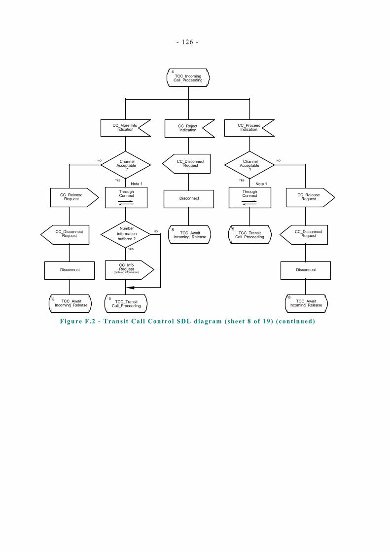
- 126 -
CC_Proceed Indication
Channel Acceptable
?
Through Connect
5TCC_Transit
Call_Proceeding
Note 1
CC_More Info Indication
YES
TCC_Incoming Call_Proceeding
4
CC_Disconnect Request
TCC_Await Incoming_Release
Disconnect
CC_Reject Indication
CC_Release Request
CC_Disconnect Request
TCC_Await Incoming_Release
Disconnect
NO
8
8
Channel Acceptable
?
Through Connect
5TCC_Transit
Call_Proceeding
Note 1YES
CC_Release Request
CC_Disconnect Request
TCC_Await Incoming_Release
Disconnect
NO
8
CC_Info Request
(buffered information)
YES
NONumber
information buffered ?
Figure F.2 - Transit Call Control SDL diagram (sheet 8 of 19) (continued)

- 127 -
CC_Alerting Indication
CC_Setup Confirmation
CC_Alerting Request
CC_Setup Response
TCC_Call Alerting
6 TCC_Call Active
7
Through Connect (if not already)
Through Connect (if not already)
Note 4Note 7
TCC_Transit Call_Proceeding
5
CC_Timeout T302
CC_Proceed Request
Note 2
TCC_Transit Call_Proceeding
5
E
Figure F.2 - Transit Call Control SDL diagram (sheet 9 of 19) (continued)
E
CC_Progress Indication
CC_Progress Request
TCC_Transit Call_Proceeding
5
Through Connect (if not already)
Note 7
CC_Proceed Indication
5TCC_Transit
Call_Proceeding
Figure F.2 - Transit Call Control SDL diagram (sheet 10 of 19) (continued)

- 128 -
6TCC_Call_Alerting
CC_Progress Indication
CC_Setup Confirmation
CC_Setup Response
CC_Progress Request
6TCC_Call_Alerting
7TCC_Call_Active
Through Connect (if not already)
Note 7
Figure F.2 - Transit Call Control SDL diagram (sheet 11 of 19) (continued)
TCC_Await Incoming_Release
TCC_Await Outgoing_Release
CC_Release Indication
CC_Release Indication
Release resources
Release resources
0 0TCC_Idle TCC_Idle
8 9
TCC_Await_Two Way_Release
CC_Release Indication
CC_Release Indication
8TCC_Await
Incoming_Release
9 TCC_Await Outgoing_Release
10
Figure F.2 - Transit Call Control SDL diagram (sheet 12 of 19) (continued)
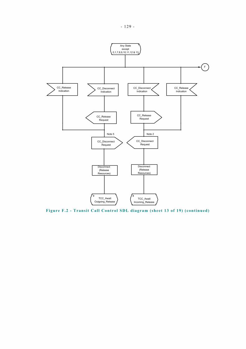
- 129 -
Any State except
0,1,7,8,9,10,11,12 & 13
CC_Release Indication
CC_Release Indication
CC_Release Request
CC_Disconnect Indication
CC_Disconnect Request
Disconnect (Release
Resources)
8TCC_Await
Incoming_Release
CC_Disconnect Indication
CC_Disconnect Request
CC_Release Request
9TCC_Await
Outgoing_Release
Disconnect (Release
Resources)
Note 2Note 5
F
Figure F.2 - Transit Call Control SDL diagram (sheet 13 of 19) (continued)
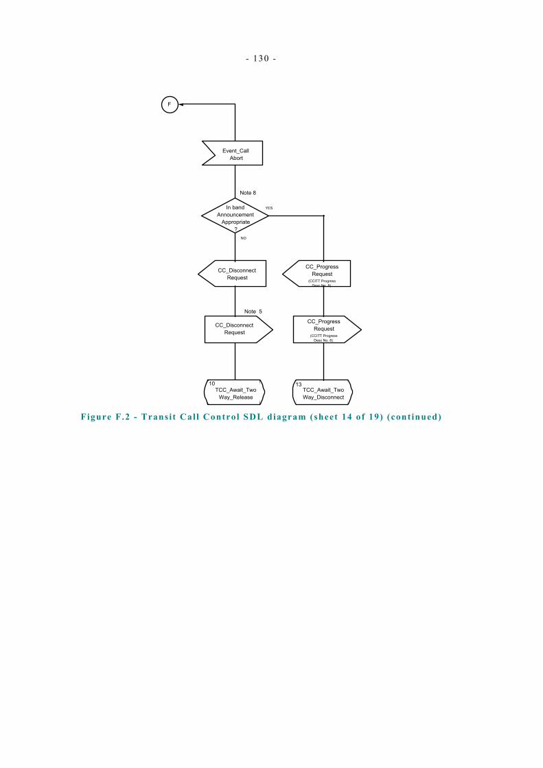
- 130 -
F
Event_Call Abort
CC_Disconnect Request
CC_Disconnect Request
10TCC_Await_Two
Way_Release
Note 5
In band Announcement
Appropriate ?
NO
YES
CC_Progress Request
(CCITT Progress Desc No. 8)
13TCC_Await_Two Way_Disconnect
Note 8
CC_Progress Request
(CCITT Progress Desc No. 8)
Figure F.2 - Transit Call Control SDL diagram (sheet 14 of 19) (continued)

- 131 -
CC_Release Indication
CC_Release Indication
CC_Release Request
CC_Disconnect Indication
CC_Disconnect Request
Disconnect (Release
Resources)
8TCC_Await
Incoming_Release
CC_Disconnect Indication
CC_Disconnect Request
CC_Release Request
9TCC_Await
Outgoing_Release
Disconnect (Release
Resources)
Note 2Note 5
G
7TCC_Call_Active
Figure F.2 - Transit Call Control SDL diagram (sheet 15 of 19) (continued)

- 132 -
G
Event_Call Abort
CC_Disconnect Request
CC_Disconnect Request
10TCC_Await_Two
Way_Release
Note 5
In band Announcement
Appropriate ?
NO
YES
CC_Progress Request
(CCITT Progress Desc No. 8)
13TCC_Await_Two Way_Disconnect
Note 8
CC_Progress Request
(CCITT Progress Desc No. 8)
Figure F.2 - Transit Call Control SDL diagram (sheet 16 of 19) (continued)
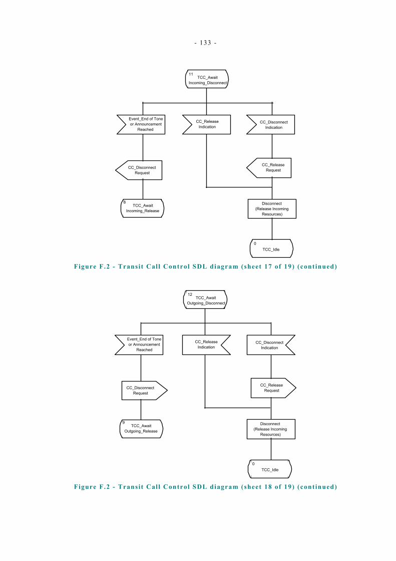
- 133 -
TCC_Await Incoming_Disconnect
11
Event_End of Tone or Announcement
Reached
CC_Release Indication
CC_Disconnect Indication
CC_Disconnect Request
8TCC_Await
Incoming_Release
0TCC_Idle
Disconnect (Release Incoming
Resources)
CC_Release Request
Figure F.2 - Transit Call Control SDL diagram (sheet 17 of 19) (continued)
TCC_Await Outgoing_Disconnect
12
Event_End of Tone or Announcement
Reached
CC_Release Indication
CC_Disconnect Indication
CC_Disconnect Request
9TCC_Await
Outgoing_Release
0TCC_Idle
Disconnect (Release Incoming
Resources)
CC_Release Request
Figure F.2 - Transit Call Control SDL diagram (sheet 18 of 19) (continued)

- 134 -
CC_Release Request
13TCC_Await_Two Way_Disconnect
CC_Disconnect Indication
CC_Release Indication
CC_Disconnect Indication
CC_Release Indication
Disconnect (Release Incoming
Resources)
TCC_Await Outgoing_Disconnect
Disconnect (Release Outgoing
Resources)
TCC_Await Incoming_Disconnect
TCC_Await_Two Way_Release
12 11 10
Event_End of Tone or Announcement
Reached
CC_Disconnect Request
CC_Disconnect Request
CC_Release Request
Figure F.2 - Transit Call Control SDL diagram (sheet 19 of 19) (concluded)
NOTES to Transit Call Control SDL diagram:
NOTE 1 This is the earliest point at which cut through of the information channel - in either, or both directions - can occur, although it need not occur at this point.
NOTE 2 The action to be taken at this point is manufacturer specific (i.e. implementation dependent) and the sequence here is give for information only.
NOTE 3 T302 protocol timer started.
NOTE 4 This is the latest point at which cut through of the information channel can occur.
NOTE 5 In state 2, Release Request is used.
NOTE 6 This request is only sent to the Outgoing Side Protocol Control if there has been information received from the Incoming Side Protocol Control which has been stored in an internal buffer.
NOTE 7 Cut through of the information channel may occur at this point. If the received message contains CCITT progress description number 1 “call is not end to end ISDN, further information may be available in band” or number 8 “in band information or appropriate pattern now available”, the information channel should be cut through in the backward direction.
NOTE 8 The optional in-band tones or announcements on call clearing may be provided in both directions, or only one direction as an implementation decision. The SDL shows only the example where tones are provided in both directions and is not intended to preclude the clearing of the call in one direction and provision of the tone or announcement in the other. In addition, if the call is aborted in the active state, the Transit PINX

- 135 -
may optionally apply the tone or announcement without sending a PROGRESS message, as the information channels are already through connected in the active state.
NOTE 9 This event occurs when the Transit PINX determines that the address information it has received is complete. This may be, for example, on receipt of CALL PROCEEDING from the Subsequent PINX, on receipt of a Sending complete information element from the Preceding PINX, or by digit analysis.

- 136 -

- 137 -
Annex G ( informative)
Bibliography
ECMA-142 Private Integrated Services Network - Circuit-mode 64 kbit/s Bearer Services - Service Description, Functional Capabilities and Information Flows (International Standard ISO/IEC 11574)
ECMA-148 Private Integrated Services Network - Specification, Functional Model and Information Flows - Identification Supplementary Services (International Standard ISO/IEC 14136)
ECMA-165 Private Integrated Services Network - Generic Functional Protocol for the Support of Supplementary Services - Inter-Exchange Signalling Procedures and Protocol (International Standard ISO/IEC 11582)
ECMA-251 Private Integrated Services Network (PISN) - Inter-Exchange Signalling Protocol - Common Information Additional Network Feature (International Standard ISO/IEC 15772)
ISO/IEC 11584 Information technology - Telecommunications and information exchange between systems - Private Integrated Services Network - Multi-rate circuit mode bearer service - Specification, functional model and information flows
CCITT Rec. G.711 Pulse code modulation (PCM) of voice frequencies (Blue Book) (1988)
ITU-T Rec. Q.930 ISDN user-network interface layer 3 - General aspects (3/93)

- 138 -
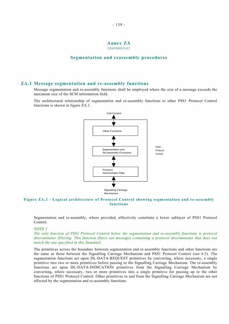
- 139 -
Annex ZA (normative)
Segmentation and reassembly procedures
ZA.1 Message segmentation and re-assembly functions Message segmentation and re-assembly functions shall be employed where the size of a message exceeds the maximum size of the SCM information field.
The architectural relationship of segmentation and re-assembly functions to other PSS1 Protocol Control functions is shown in figure ZA.1.
Other Functions
Segmentation andRe-assembly Functions
ProtocolDiscriminator Filter
Call Control
Signalling CarriageMechanism
PSS1ProtocolControl
Figure ZA.1 - Logical architecture of Protocol Control showing segmentat ion and re-assembly
funct ions
Segmentation and re-assembly, where provided, effectively constitute a lower sublayer of PSS1 Protocol Control.
NOTE 1 The only function of PSS1 Protocol Control below the segmentation and re-assembly functions is protocol discriminator filtering. This function filters out messages containing a protocol discriminator that does not match the one specified in this Standard.
The primitives across the boundary between segmentation and re-assembly functions and other functions are the same as those between the Signalling Carriage Mechanism and PSS1 Protocol Control (see 6.3). The segmentation functions act upon DL-DATA-REQUEST primitives by converting, where necessary, a single primitive into two or more primitives before passing to the Signalling Carriage Mechanism. The re-assembly functions act upon DL-DATA-INDICATION primitives from the Signalling Carriage Mechanism by converting, where necessary, two or more primitives into a single primitive for passing up to the other functions of PSS1 Protocol Control. Other primitives to and from the Signalling Carriage Mechanism are not affected by the segmentation and re-assembly functions.
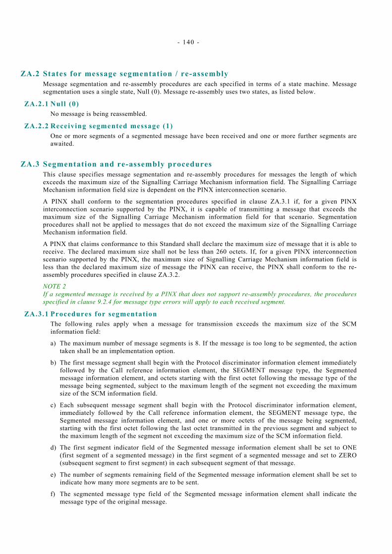
- 140 -
ZA.2 States for message segmentation / re-assembly Message segmentation and re-assembly procedures are each specified in terms of a state machine. Message segmentation uses a single state, Null (0). Message re-assembly uses two states, as listed below.
ZA.2.1 Null (0) No message is being reassembled.
ZA.2.2 Receiving segmented message (1) One or more segments of a segmented message have been received and one or more further segments are awaited.
ZA.3 Segmentation and re-assembly procedures This clause specifies message segmentation and re-assembly procedures for messages the length of which exceeds the maximum size of the Signalling Carriage Mechanism information field. The Signalling Carriage Mechanism information field size is dependent on the PINX interconnection scenario.
A PINX shall conform to the segmentation procedures specified in clause ZA.3.1 if, for a given PINX interconnection scenario supported by the PINX, it is capable of transmitting a message that exceeds the maximum size of the Signalling Carriage Mechanism information field for that scenario. Segmentation procedures shall not be applied to messages that do not exceed the maximum size of the Signalling Carriage Mechanism information field.
A PINX that claims conformance to this Standard shall declare the maximum size of message that it is able to receive. The declared maximum size shall not be less than 260 octets. If, for a given PINX interconnection scenario supported by the PINX, the maximum size of Signalling Carriage Mechanism information field is less than the declared maximum size of message the PINX can receive, the PINX shall conform to the re-assembly procedures specified in clause ZA.3.2.
NOTE 2 If a segmented message is received by a PINX that does not support re-assembly procedures, the procedures specified in clause 9.2.4 for message type errors will apply to each received segment.
ZA.3.1 Procedures for segmentation The following rules apply when a message for transmission exceeds the maximum size of the SCM information field:
a) The maximum number of message segments is 8. If the message is too long to be segmented, the action taken shall be an implementation option.
b) The first message segment shall begin with the Protocol discriminator information element immediately followed by the Call reference information element, the SEGMENT message type, the Segmented message information element, and octets starting with the first octet following the message type of the message being segmented, subject to the maximum length of the segment not exceeding the maximum size of the SCM information field.
c) Each subsequent message segment shall begin with the Protocol discriminator information element, immediately followed by the Call reference information element, the SEGMENT message type, the Segmented message information element, and one or more octets of the message being segmented, starting with the first octet following the last octet transmitted in the previous segment and subject to the maximum length of the segment not exceeding the maximum size of the SCM information field.
d) The first segment indicator field of the Segmented message information element shall be set to ONE (first segment of a segmented message) in the first segment of a segmented message and set to ZERO (subsequent segment to first segment) in each subsequent segment of that message.
e) The number of segments remaining field of the Segmented message information element shall be set to indicate how many more segments are to be sent.
f) The segmented message type field of the Segmented message information element shall indicate the message type of the original message.

- 141 -
g) Once the first segment has been transmitted on a particular SCM connection, then all remaining segments of that message shall be sent (in order) before any other message (segmented or not) for any other call reference is sent on that SCM connection. Only failure conditions (e.g., SCM failure) shall cause the transmission of a segmented message to be aborted.
h) The octet order of the segmented message shall be preserved regardless of segment boundary.
ZA.3.2 Procedures for re-assembly The following rules apply to the receipt and re-assembly of segmented messages:
a) A re-assembly function, on receiving a message of type SEGMENT containing the Segmented message information element as the first information element after the message type, shall treat that message as a segment.
b) A re-assembly function in the Null state, on receiving a segment in which the first segment indicator field of the Segmented message information element is set to ONE (first segment of segmented message) and the number of segments remaining field of the Segmented message information element is set to a value greater than 0 and not exceeding 7, shall enter the Receiving segmented message state and save the segment contents. Timer T314 shall be initialised. Timer T314 is used to prevent the re-assembly function waiting indefinitely to receive the next message segment.
c) A re-assembly function in the Receiving segmented message state, on receiving a segment in which the call reference is equal to the call reference of the first segment received, the first segment indicator field of the Segmented message information element is set to ZERO (subsequent segment to first segment), the number of segments remaining field of the Segmented message information element is set to a value one less than the value in the previously received segment, and the segmented message type field has a value equal to the value of that field in the first segment received, shall treat the segment as a valid next segment.
d) A re-assembly function in the Receiving segmented message state, on receiving a valid next segment in which the number of segments remaining field has a value greater than zero, shall save the segment contents along with the saved contents of the previous segment or segments, restart timer T314, and remain in the Receiving segmented message state.
e) A re-assembly function in the Receiving segmented message state, on receiving a valid next segment in which the number of segments remaining field has a value equal to zero, shall stop timer T314, deliver the accumulated segments, including the last segment, as a single message for further PSS1 Protocol Control processing, and enter the Null state. The message delivered shall have a call reference equal to that in each received segment and a message type equal to that in the segmented message type field of the Segmented message information element of each received segment. Octets following the Segmented message information element in each received segment shall be included in the delivered message in the order received.
f) A re-assembly function in the Null state shall deliver for further PSS1 Protocol Control processing any received message of type other than SEGMENT or that is too short to contain a message type.
g) A re-assembly function in the Null state shall discard any received message of type SEGMENT that is not a valid first segment. Any other action taken shall be an implementation option. This applies to the following:
− messages of type SEGMENT without a valid Segmented message information element following the message type;
− segments in which the first segment indicator field of the Segmented message information element is set to ZERO (subsequent segment to first segment);
− segments in which the number of segments remaining field of the Segmented message information element has a value 0 or a value exceeding 7.
h) A re-assembly function in the Receiving segmented message state shall discard any saved segments, stop timer T314 and enter the Null state on receipt of any message which is not a valid next segment. This applies to the following:
− Messages with a different call reference from that in the first received segment;

- 142 -
− Messages of type other than SEGMENT;
− Messages of type SEGMENT without a valid Segmented message information element following the message type;
− Segments in which the first segment indicator field of the Segmented message information element is set to ONE (first segment of segmented message);
− Segments in which the number of segments remaining field of the Segmented message information element has a value which is not one less than the value in the previously received segment;
− Segments in which the segmented message type field of the Segmented message information element has a value which is not equal to the value in the first received segment.
In the case of a message with a different call reference from that in the first received segment or a message with a message type other than SEGMENT, the received message shall be processed as if it had been received while in the Null state. In all other cases the received message shall be discarded. Any other action taken shall be an implementation option.
i) On expiry of timer T314, the re-assembly function shall discard any saved segments and enter the Null state. Any other action taken shall be an implementation option.
j) If a DL-RELEASE-INDICATION or DL-ESTABLISH-INDICATION is received while the re-assembly function is in the Receiving segmented message state, the re-assembly function shall discard any saved segments, stop timer T314, and enter the Null state. The DL-RELEASE-INDICATION or DL-ESTABLISH-INDICATION shall be delivered for further PSS1 Protocol Control processing.
ZA.3.3 SDL for segmentation and re-assembly (informative) In the figures that follow, input signals from the left (except those indicating timer expiry) and output signals to the left are from and to the Other Functions of PSS1 Protocol Control, and input signals from the right and output signals to the right are from and to the Signalling Carriage Mechanism, via the Protocol Discriminator Filter.
Figure ZA.2 shows the procedures for message segmentation in SDL form. The SDL process forms part of the Segmentation and Re-Assembly Functions of PSS1 Protocol Control (see ZA.1) and intercepts all primitives sent from Other Functions of PSS1 Protocol Control towards the Signalling Carriage Mechanism.
Figures ZA.3, ZA.4 and ZA.5 show the procedures for message re-assembly in SDL form. The SDL process forms part of the Segmentation and Re-assembly Functions of PSS1 Protocol Control (see ZA.1) and intercepts all primitives received from the Signalling Carriage Mechanism via the Protocol Discriminator Filter.
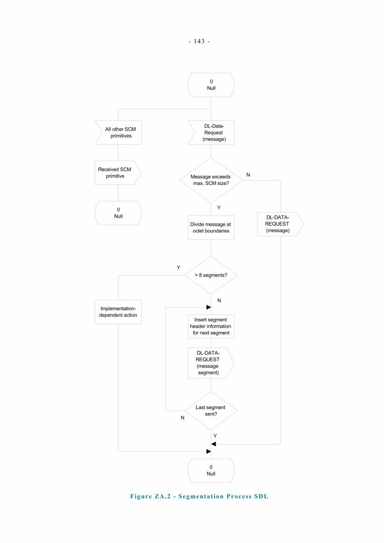
- 143 -
0Null
DL-Data-Request
(message)
All other SCM primitives
Received SCM primitive
0Null
Message exceeds max. SCM size?
Divide message at octet boundaries
> 8 segments?
Insert segment header information
for next segment
DL-DATA-REQUEST (message segment)
Last segment sent?
0Null
Implementation-dependent action
DL-DATA-REQUEST (message)
N
Y
Y
N
N
Y
Figure ZA.2 - Segmentat ion Process SDL
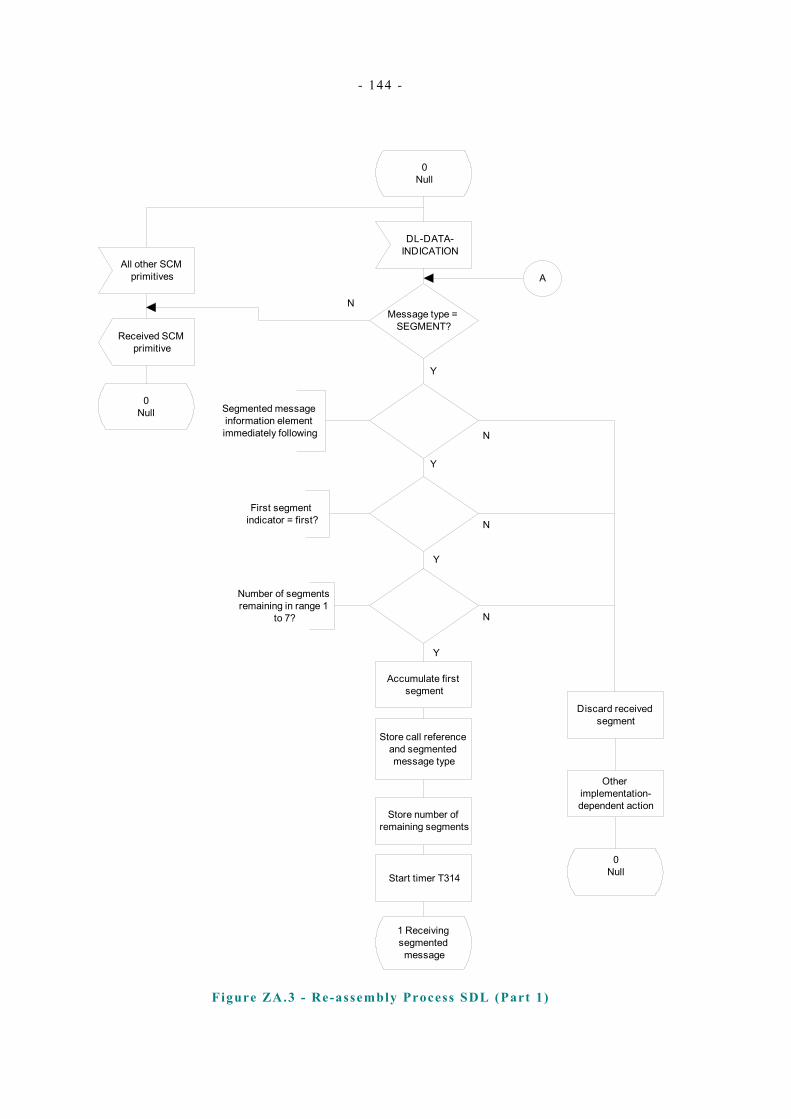
- 144 -
0Null
DL-DATA-INDICATION
All other SCM primitives
Received SCM primitive
0Null
Message type = SEGMENT?
N
Y
Segmented message information element immediately following
First segment indicator = first?
Number of segments remaining in range 1
to 7?
Y
Y
N
N
N
Y
Discard received segment
Other implementation-dependent action
0Null
Accumulate first segment
Store call reference and segmented message type
Store number of remaining segments
Start timer T314
1 Receiving segmented message
A
Figure ZA.3 - Re-assembly Process SDL (Part 1)
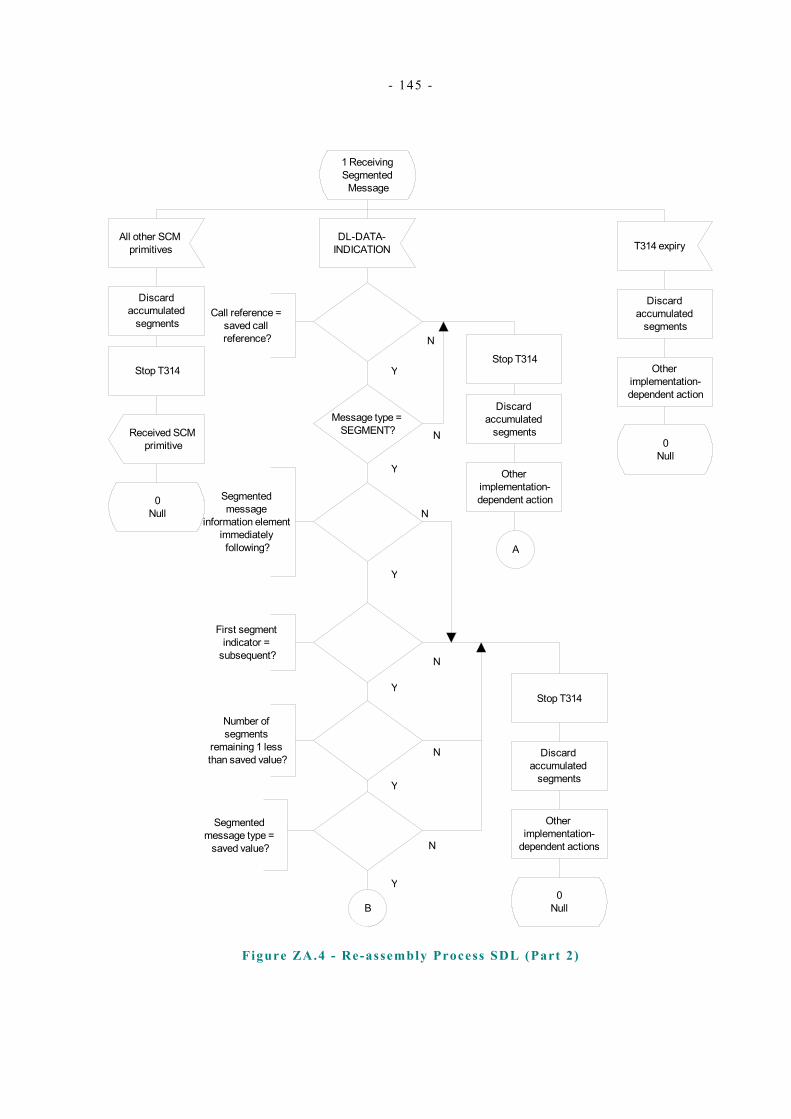
- 145 -
1 Receiving Segmented
Message
DL-DATA-INDICATION
All other SCM primitives T314 expiry
Discard accumulated
segments
Stop T314
Received SCM primitive
0Null
Message type = SEGMENT?
Call reference = saved call reference?
Y
Y
N
N
Segmented message
information element immediately following?
First segment indicator =
subsequent?
Number of segments
remaining 1 less than saved value?
Segmented message type =
saved value?
B
Y
N
Y
N
Y
N
Discard accumulated
segments
Other implementation-dependent action
0Null
Stop T314
Discard accumulated
segments
Other implementation-
dependent actions
0Null
Stop T314
Discard accumulated
segments
A
Other implementation-dependent action
N
Y
Figure ZA.4 - Re-assembly Process SDL (Part 2)
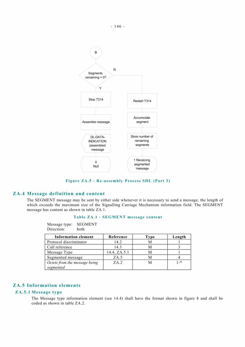
- 146 -
B
Segments remaining = 0?
Assemble message
Restart T314
Accumulate segment
DL-DATA-INDICATION (assembled
message
0Null
Y
N
1 Receiving segmented
message
Store number of remaining segments
Stop T314
Figure ZA.5 - Re-assembly Process SDL (Part 3)
ZA.4 Message definition and content The SEGMENT message may be sent by either side whenever it is necessary to send a message, the length of which exceeds the maximum size of the Signalling Carriage Mechanism information field. The SEGMENT message has content as shown in table ZA.1.
Table ZA.1 - SEGMENT message content
Message type: SEGMENT Direction: both
Information element Reference Type Length Protocol discriminator 14.2 M 1 Call reference 14.3 M 3 Message Type 14.4, ZA.5.1 M 1 Segmented message ZA.5 M 4 Octets from the message being segmented
ZA.2 M 1-*
ZA.5 Information elements ZA.5.1 Message type
The Message type information element (see 14.4) shall have the format shown in figure 8 and shall be coded as shown in table ZA.2.
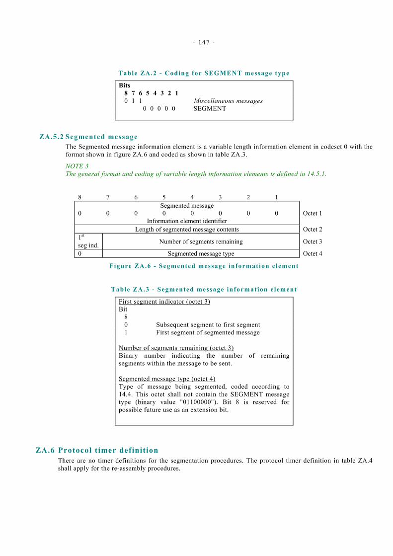
- 147 -
Table ZA.2 - Coding for SEGMENT message type
Bits 8 7 6 5 4 3 2 1 0 1 1 Miscellaneous messages 0 0 0 0 0 SEGMENT
ZA.5.2 Segmented message The Segmented message information element is a variable length information element in codeset 0 with the format shown in figure ZA.6 and coded as shown in table ZA.3.
NOTE 3 The general format and coding of variable length information elements is defined in 14.5.1.
8 7 6 5 4 3 2 1 Segmented message
0 0 0 0 0 0 0 0 Octet 1 Information element identifier
Length of segmented message contents Octet 2 1st seg ind. Number of segments remaining Octet 3
0 Segmented message type Octet 4
Figure ZA.6 - Segmented message information element
Table ZA.3 - Segmented message information element
First segment indicator (octet 3) Bit 8 0 Subsequent segment to first segment 1 First segment of segmented message Number of segments remaining (octet 3) Binary number indicating the number of remaining segments within the message to be sent. Segmented message type (octet 4) Type of message being segmented, coded according to 14.4. This octet shall not contain the SEGMENT message type (binary value "01100000"). Bit 8 is reserved for possible future use as an extension bit.
ZA.6 Protocol timer definition There are no timer definitions for the segmentation procedures. The protocol timer definition in table ZA.4 shall apply for the re-assembly procedures.

- 148 -
Table ZA.4 - Protocol t imer def init ion for re-assembly procedures
Timer number
Timer value
Call state Cause for start
Normally terminated
Action to be taken when
timer expires
Status
T314 4s, ±10% Receiving segmented message
Message segment received
Last message segment received
Discard message
Mandatory if the associated procedures are implemented
- 149 -
Annex ZB (normative)
Additional progress descriptions
ZB.1 Introduction The coding of the Progress indicator information element in 14.5.17 defines several progress descriptions for interworking situations. The procedures in 10 specify the circumstances when each is used. In particular, progress descriptions are transmitted over an inter-PINX link:
− by an Incoming Gateway PINX for calls entering the PISN from another network; and,
− by an Outgoing Gateway PINX for calls passing from the PISN to another network.
This annex specifies some additional codings (and their use) for the progress description field of the Progress indicator information element. These additional progress descriptions can be used to convey supplementary information about the interworking environment applicable to a particular call.
It is mandatory to support the progress descriptions and procedures specified in this annex. The requirements specified in this annex are additional to the requirements specified in 10 of this Standard.
ZB.2 General requirements In addition to the progress descriptions listed in 14.5.17, a PINX shall also support the following progress descriptions:
− 16 "interworking with a public network";
− 17 "interworking with a network unable to supply a release signal";
− 18 "interworking with a network unable to supply a release signal before answer"; and
− 19 "interworking with a network unable to supply a release signal after answer".
A PINX shall be capable of sending ALERTING, CONNECT, PROGRESS and SETUP messages containing up to three Progress indicator information elements, as appropriate to the circumstances of a particular call.
NOTE 1 More than one Progress indicator information element may be sent in the same message, to indicate different conditions.
A PINX shall also be capable of receiving and acting upon such messages, including in the case of a Transit PINX, passing all Progress indicators received on to the next PINX.
ZB.3 Coding requirements for additional progress descriptions The Progress indicator information element defined in 14.5.17 is a variable length category 1 (see 10.4.11.2) information element with the format shown in figure 23. Up to three Progress indicator information elements may appear in a single message (to indicate more than one condition).
NOTE 2 The Progress indicator information element can be conveyed in ALERTING, CONNECT, PROGRESS, and SETUP messages. Clauses 13.2.1, 13.2.3, 13.2.7 and 13.2.10 respectively define these messages.
The CCITT standardised coding for the information element is shown in table 32. The coding for the Additional progress descriptions is shown in table ZB.1.
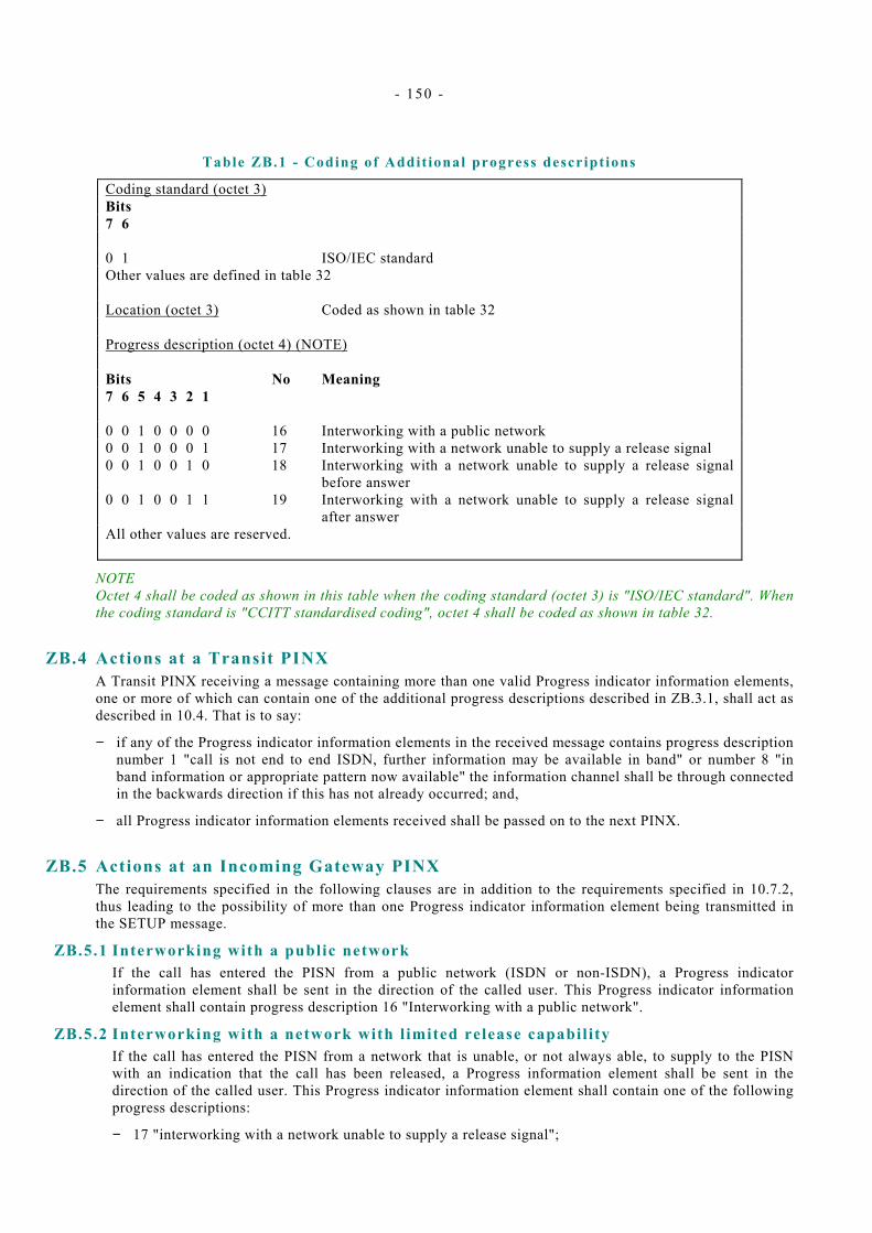
- 150 -
Table ZB.1 - Coding of Addit ional progress descript ions
Coding standard (octet 3) Bits 7 6 0 1 ISO/IEC standard Other values are defined in table 32 Location (octet 3) Coded as shown in table 32 Progress description (octet 4) (NOTE) Bits No Meaning 7 6 5 4 3 2 1 0 0 1 0 0 0 0 16 Interworking with a public network 0 0 1 0 0 0 1 17 Interworking with a network unable to supply a release signal 0 0 1 0 0 1 0 18 Interworking with a network unable to supply a release signal
before answer 0 0 1 0 0 1 1 19 Interworking with a network unable to supply a release signal
after answer All other values are reserved.
NOTE Octet 4 shall be coded as shown in this table when the coding standard (octet 3) is "ISO/IEC standard". When the coding standard is "CCITT standardised coding", octet 4 shall be coded as shown in table 32.
ZB.4 Actions at a Transit PINX A Transit PINX receiving a message containing more than one valid Progress indicator information elements, one or more of which can contain one of the additional progress descriptions described in ZB.3.1, shall act as described in 10.4. That is to say:
− if any of the Progress indicator information elements in the received message contains progress description number 1 "call is not end to end ISDN, further information may be available in band" or number 8 "in band information or appropriate pattern now available" the information channel shall be through connected in the backwards direction if this has not already occurred; and,
− all Progress indicator information elements received shall be passed on to the next PINX.
ZB.5 Actions at an Incoming Gateway PINX The requirements specified in the following clauses are in addition to the requirements specified in 10.7.2, thus leading to the possibility of more than one Progress indicator information element being transmitted in the SETUP message.
ZB.5.1 Interworking with a public network If the call has entered the PISN from a public network (ISDN or non-ISDN), a Progress indicator information element shall be sent in the direction of the called user. This Progress indicator information element shall contain progress description 16 "Interworking with a public network".
ZB.5.2 Interworking with a network with l imited release capabil ity If the call has entered the PISN from a network that is unable, or not always able, to supply to the PISN with an indication that the call has been released, a Progress information element shall be sent in the direction of the called user. This Progress indicator information element shall contain one of the following progress descriptions:
− 17 "interworking with a network unable to supply a release signal";
- 151 -
− 18 "interworking with a network unable to supply a release signal before answer"; or,
− 19 "interworking with a network unable to supply a release signal after answer".
Progress description number 18 shall be used if the other network is able to indicate release after it has received an answer signal from the PISN, but is not always able to indicate release prior to receiving an answer signal. In this case, the other network will rely on receiving a release signal from the PISN if answer does not occur within a reasonable time.
Progress description number 19 shall be used if the other network is able to indicate release prior to the receipt of an answer signal from the PISN, but is not always able to indicate release after receiving an answer signal. In this case, the other network will rely on receiving a release signal from the PISN when release is initiated by the called user.
Progress description number 17 shall be used if the other network is not always able to indicate release prior to answer and is not always able to indicate release after answer. In this case, the other network will rely on receiving a release signal from the PISN if answer does not occur within a reasonable time and when release is initiated by the called user.
ZB.5.3 On receipt of a PROGRESS, ALERTING or CONNECT message Action, if any, on receipt of any of the additional progress descriptions specified in table ZB.1 during call establishment is an implementation matter.
NOTE 3 The Incoming Gateway PINX can make use of these progress descriptions to determine whether the call is to be allowed to continue. However, normally the peer Outgoing Gateway PINX will have avoided the establishment of undesirable calls, based on progress descriptions received in the SETUP message (see ZB.6.1).
ZB.5.4 On receipt of a Progress indicator information element subsequent to call establishment Action, if any, on receipt of any of the additional progress descriptions specified in table ZB.1 subsequent to call establishment is an implementation matter.
NOTE 4 Any of these progress descriptions can be received from a peer Gateway PINX subsequent to the use of a supplementary service such as Call Transfer. The Incoming Gateway PINX can use this information in conjunction with local knowledge to determine whether the call is to be allowed to continue. Checks can be similar to those conducted at an Outgoing Gateway PINX on receipt of a SETUP message (see ZB.6.1).
ZB.6 Actions at an Outgoing Gateway PINX The requirements specified in the following clauses are in addition to the requirements specified in 10.8.3, thus leading to the possibility of more than one Progress indicator information element being transmitted.
ZB.6.1 On receipt of the SETUP message Certain information in the Progress indicator information element(s) contained within a SETUP message received by an Outgoing Gateway PINX may affect the decision of the PINX to route the call to another network. In particular, the Outgoing Gateway PINX shall not establish a call that cannot be released. This can be determined by the presence of a Progress indicator information element containing one of the progress descriptions: 17 "interworking with a network unable to supply a release signal", 18 "interworking with a network unable to supply a release signal before answer", or 19 "interworking with a network unable to supply a release signal after answer", and the Outgoing Gateway PINX's knowledge of the ability of the other network to signal release.
In addition, the presence of a Progress indicator information element containing progress description 16 "interworking with a public network" may influence routeing.
NOTE 5 For example, the establishment of a call between two public networks can be prevented, if required.

- 152 -
ZB.6.2 Interworking with a public network If the call is to enter a public network (ISDN or non-ISDN), a Progress indicator information element shall be sent in the direction of the calling user. This Progress indicator information element shall contain progress description 16 "Interworking with a public network".
ZB.6.3 Interworking with a network with l imited release capabil ity If the call is to enter a network that is unable, or not always able, to supply an indication to the PISN that the call has been released, a Progress indicator information element shall be sent in the direction of the calling user. This Progress indicator information element shall contain one of the following progress descriptions:
− 17 "interworking with a network unable to supply a release signal";
− 18 "interworking with a network unable to supply a release signal before answer"; or,
− 19 "interworking with a network unable to supply a release signal after answer".
Progress description number 18 shall be used if the other network is able to indicate release after it has sent an answer signal to the PISN, but is not always able to indicate release in the event of no reply. The other network will rely on receiving a release signal from the PISN when release is initiated by the calling user or if answer does not occur within a reasonable time.
Progress description number 19 shall be used if the other network is able to indicate release prior to sending an answer signal to the PISN, but is not always able to indicate release after sending an answer signal. In this case, the other network will rely on receiving a release signal from the PISN when release is initiated by the calling user.
Progress description number 17 shall be used if the other network is not always able to indicate release prior to answer and is not always able to indicate release after answer. In this case, the other network will rely on receiving a release signal from the PISN if answer does not occur within a reasonable time and when release is initiated by the calling user.
ZB.6.4 On receipt of a Progress indicator information element subsequent to call establishment Action, if any, on receipt of any of the additional progress descriptions specified in table ZB.1 subsequent to call establishment is an implementation matter.
NOTE 6 Any of these progress descriptions can be received from a peer Gateway PINX subsequent to the use of a supplementary service such as Call Transfer. The Outgoing Gateway PINX can use this information in conjunction with local knowledge to determine whether the call is to be allowed to continue. Checks can be similar to those conducted at an Outgoing Gateway PINX on receipt of a SETUP message (see ZB.6.1).
ZB.7 Actions at an Originating PINX or a Terminating PINX Action, if any, on receipt of any of the additional progress descriptions specified in table ZB.1 is an implementation matter. Possible actions include the following:
− provision of an appropriate indication to the user on receipt of progress description 16;
− use later in the call as part of the process of determining whether a request for a supplementary service such as Call Transfer should be accepted.


Free printed copies can be ordered from: ECMA 114 Rue du Rhône CH-1204 Geneva Switzerland
Fax: +41 22 849.60.01 Email: [email protected]
Files of this Standard can be freely downloaded from the ECMA web site (www.ecma.ch). This site gives full information on ECMA, ECMA activities, ECMA Standards and Technical Reports.

ECMA 114 Rue du Rhône CH-1204 Geneva Switzerland
See inside cover page for obtaining further soft or hard copies.