broadband private integrated services network (b-pisn) - inter
TRANSCRIPT

Standard ECMA-298December 1999
S t a n d a r d i z i n g I n f o r ma t i o n a n d C o mmu n i c a t i o n S y s t e ms
Phone : +41 22 849 .60 .00 - Fax : +41 22 849 .60 .01 - URL: h t tp : / /www.ecma.ch - I n te rne t : he [email protected]
Broadband Private IntegratedServices Network (B-PISN) -Inter-Exchange Signalling Protocol –Separated Bearer Control (SBC)

..

Standard ECMA-298December 1999
S t a n d a r d i z i n g I n f o r ma t i o n a n d C o mmu n i c a t i o n S y s t e ms
Phone : +41 22 849 .60 .00 - Fax : +41 22 849 .60 .01 - URL: h t tp : / /www.ecma.ch - I n te rne t : he [email protected]
IW ECMA-298.DOC 03-01-00 10,40
Broadband Private IntegratedServices Network (B-PISN) -Inter-Exchange Signalling Protocol –Separated Bearer Control (SBC)
(B-QSIG-SBC)

..

Brief History
This Standard is one of a series of ECMA Standards defining services and signalling protocols applicable toBroadband Private Integrated Services Networks (B-PISNs). The series uses B-ISDN concepts as developed by ITU-Tand conforms to the framework of International Standards for Open Systems Interconnection as defined by ISO/IEC.It has been produced under ETSI work item DEN/ECMA-00160.
This particular Standard specifies the signalling protocol for use at the Q reference point for separated bearer control(B-QSIG-SBC).
This Standard is based upon the practical experience of ECMA member companies and the results of their active andcontinuous participation in the work of ISO/IEC JTC1, ITU-T, ETSI and other international and nationalstandardization bodies. It represents a pragmatic and widely based consensus.
This Standard has been adopted by the ECMA General Assembly of December 1999.

..

- i -
Table of contents
1 Scope 1
2 Conformance 1
3 References (normative) 1
4 Definitions 1
4.1 External definitions 1
4.2 Other definitions 2
4.2.1 Connection state 2
4.2.2 Bearer identifier 2
4.2.3 Call segment 2
4.2.4 Call segment identifier 2
4.2.5 Preceding side 2
4.2.6 Succeeding side 2
4.2.7 Side 2
4.2.8 Signalling AAL (SAAL) 2
4.2.9 Preceding PINX 2
4.2.10 Succeeding PINX 2
4.2.11 Preceding PINX with call/bearer co-ordination 2
4.2.12 Preceding PINX without co-ordination function 2
4.2.13 Succeeding PINX without co-ordination function 3
4.2.14 Succeeding PINX with co-ordination function 3
5 List of acronyms 3
6 Description 3
6.1 Separation of call control and bearer control 3
6.2 Relationship to call control architecture 3
6.3 Capabilities supported by this Standard 4
6.4 General overview 4
7 Operational requirements 4
7.1 Provision and withdrawal 4
7.2 Requirements on the preceding side 5
7.3 Requirements on the succeeding side 5
8 Primitive definitions and state definitions 5
8.1 Primitive definitions 5
8.2 State definitions 5
8.2.1 B-QSIG connection states 5
9 Coding requirements 5
9.1 Messages 5
9.1.1 Modification to messages defined in ECMA-266 5
- i i -
9.2 Information elements 6
9.2.1 Call association 6
9.2.2 Bearer identifier 7
9.2.3 Other information elements 7
10 Signalling procedures at the Q reference point 7
10.1 Introduction 7
10.2 Establishment of a bearer 8
10.2.1 Additional procedures at a preceding side 8
10.2.2 Additional procedures at a succeeding side 8
10.3 Procedures for joining bearer connections on adjacent call segments 9
10.4 Additional procedures at a Transit PINX 9
10.5 Clearing of a Connection 9
11 Interworking with other networks 10
12 Interworking with supplementary services 10
13 Parameter values 10
14 Dynamic description SDLs 10
Annex A - Protocol Implementation Conformance Statement (PICS) proforma 11
Annex B - Guidelines for the use of the instruction indicator 21

1 ScopeThis Standard defines the signalling protocol for the purpose of bearer control at the Q-reference pointbetween Private Integrated Services Network Exchanges (PINXs) connected together within a BroadbandPrivate Integrated Services Network (B-PISN) employing Asynchronous Transfer Mode (ATM). ThisStandard is part of the B-QSIG signalling system.
This Standard specifies the essential features, procedures, and messages required for establishing, maintainingand clearing of bearer connections to point-to-point multiconnection calls at the B-QSIG interface in afunctionally separated call and bearer control environment. Bearers are controlled independently by means ofa separated call control protocol. The separated call control protocol is assumed to be that specified inECMA-294.
This Standard is applicable to PINXs that support separated call and bearer control protocol at the Q referencepoint. The Q reference point is defined in ISO/IEC 11579-1.
2 ConformanceIn order to conform to this Standard, a PINX shall satisfy the requirements identified in the ProtocolImplementation Conformance Statement (PICS) proforma in annex A.
3 References (normative)The following standards/recommendations contain provisions, which, through reference in this text, constituteprovisions of this Standard. All standards are subject to revision, and parties to agreements based on thisStandard are encouraged to investigate the possibility of applying the most recent editions of the standardsindicated below.
ECMA-266 Broadband Private Integrated Services Network (B-PISN) – Inter-Exchange SignallingProtocol – Basic Call/Connection Control (International Standard ISO/IEC 13247)
ECMA-294 Broadband Integrated Services Digital Network (B-ISDN) and Broadband PrivateIntegrated Services Network (B-PISN) - Digital Subscriber Signalling System No. two(DSS2), Broadband Inter-Exchange Signalling (B-QSIG), and Signalling System No. 7(SS7) - Call Control in a Separated Call and Bearer Control Environment - Part 1:Protocol Specification
ISO/IEC 11579-1 Information technology - Telecommunications and information exchange betweensystems - Private Integrated Services Network - Part 1: Reference configuration for PISNExchanges (PINX)
ITU-T Rec. I.112 Vocabulary of terms for ISDNs (1993)
ITU-T Rec. I.321 B-ISDN protocol reference model and its application (1991)
ITU-T Rec. I.371 Traffic control and congestion control in B-ISDN (1996)
ITU-T Rec. Q.9 Vocabulary of switching and signalling terms (Blue Book) (1988)
4 DefinitionsFor the purposes of this Standard the following definitions apply.
4.1 External definitionsThis Standard uses the following terms defined in other documents:
− ATM transfer capability (ATC) (ITU-T Rec. I.371)
− bearer (ECMA-294)
− bearer control (ECMA-294)
− bearer control entity (BC entity) (ECMA-294)
- 2 -
− call (ECMA-294)
− call control (ECMA-294)
− call control entity (CC entity) (ECMA-294)
− call control signalling service user (ECMA-294)
− connection (ITU-T Rec. Q.9)
− Inter-PINX Link (IPL) (ECMA-266)
− private integrated services network (PISN) (ISO/IEC 11579-1)
− private integrated services network exchange (PINX) (ISO/IEC 11579-1)
− signalling (ITU-T Rec. I.112)
− user plane (ITU-T Rec. I.321)
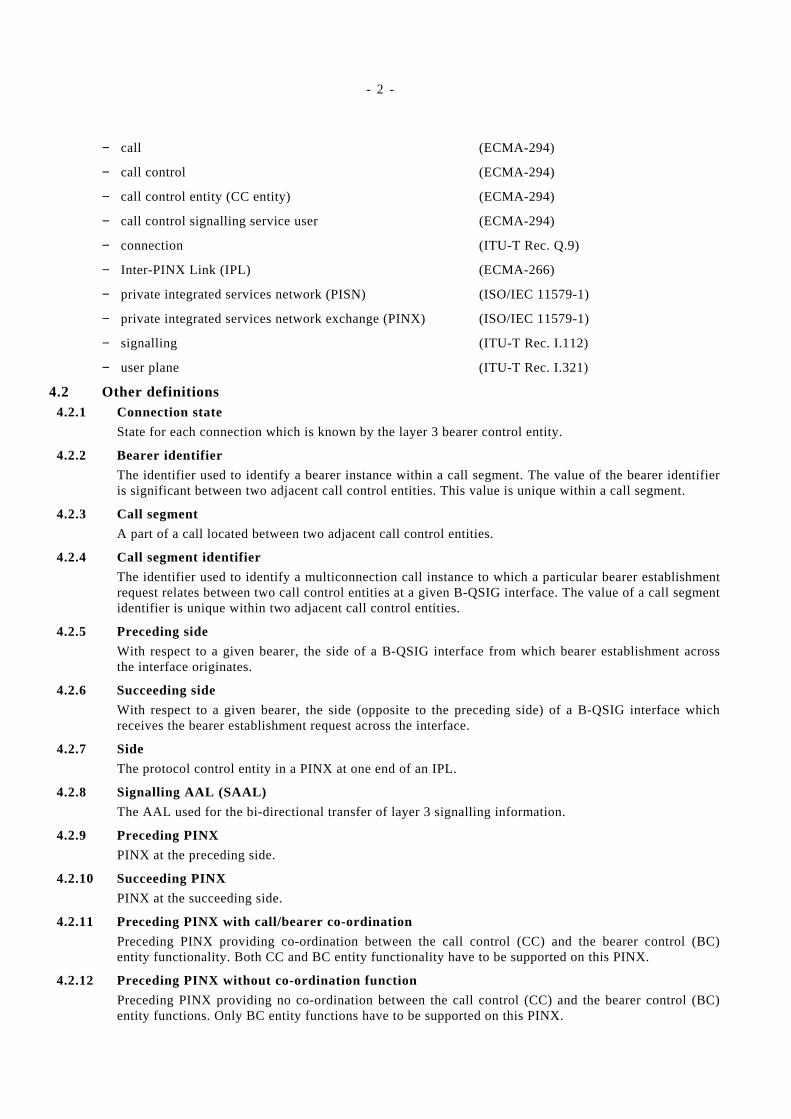
4.2 Other definitions4.2.1 Connection state
State for each connection which is known by the layer 3 bearer control entity.
4.2.2 Bearer identifier
The identifier used to identify a bearer instance within a call segment. The value of the bearer identifieris significant between two adjacent call control entities. This value is unique within a call segment.
4.2.3 Call segment
A part of a call located between two adjacent call control entities.
4.2.4 Call segment identifier
The identifier used to identify a multiconnection call instance to which a particular bearer establishmentrequest relates between two call control entities at a given B-QSIG interface. The value of a call segmentidentifier is unique within two adjacent call control entities.
4.2.5 Preceding side
With respect to a given bearer, the side of a B-QSIG interface from which bearer establishment acrossthe interface originates.
4.2.6 Succeeding side
With respect to a given bearer, the side (opposite to the preceding side) of a B-QSIG interface whichreceives the bearer establishment request across the interface.
4.2.7 Side
The protocol control entity in a PINX at one end of an IPL.
4.2.8 Signalling AAL (SAAL)
The AAL used for the bi-directional transfer of layer 3 signalling information.
4.2.9 Preceding PINX
PINX at the preceding side.
4.2.10 Succeeding PINX
PINX at the succeeding side.
4.2.11 Preceding PINX with call/bearer co-ordination
Preceding PINX providing co-ordination between the call control (CC) and the bearer control (BC)entity functionality. Both CC and BC entity functionality have to be supported on this PINX.
4.2.12 Preceding PINX without co-ordination function
Preceding PINX providing no co-ordination between the call control (CC) and the bearer control (BC)entity functions. Only BC entity functions have to be supported on this PINX.
- 3 -
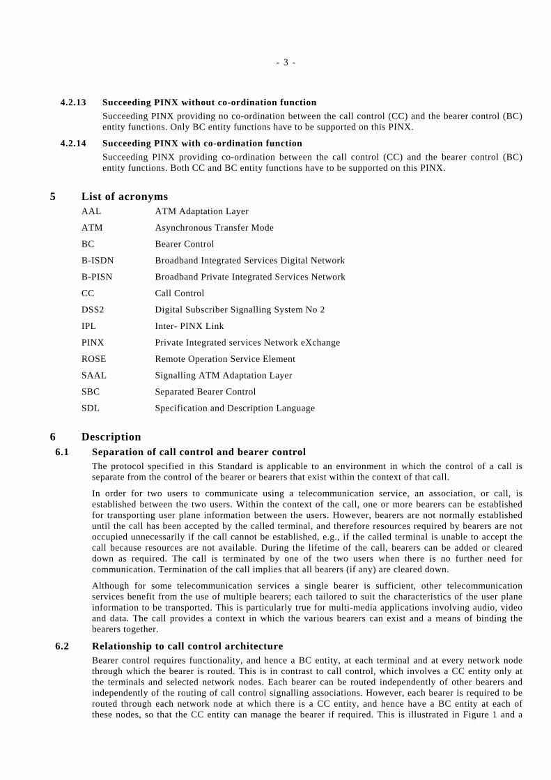
4.2.13 Succeeding PINX without co-ordination function
Succeeding PINX providing no co-ordination between the call control (CC) and the bearer control (BC)entity functions. Only BC entity functions have to be supported on this PINX.
4.2.14 Succeeding PINX with co-ordination function
Succeeding PINX providing co-ordination between the call control (CC) and the bearer control (BC)entity functions. Both CC and BC entity functions have to be supported on this PINX.
5 List of acronymsAAL ATM Adaptation Layer
ATM Asynchronous Transfer Mode
BC Bearer Control
B-ISDN Broadband Integrated Services Digital Network
B-PISN Broadband Private Integrated Services Network
CC Call Control
DSS2 Digital Subscriber Signalling System No 2
IPL Inter- PINX Link
PINX Private Integrated services Network eXchange
ROSE Remote Operation Service Element
SAAL Signalling ATM Adaptation Layer
SBC Separated Bearer Control
SDL Specification and Description Language
6 Description6.1 Separation of call control and bearer control
The protocol specified in this Standard is applicable to an environment in which the control of a call isseparate from the control of the bearer or bearers that exist within the context of that call.
In order for two users to communicate using a telecommunication service, an association, or call, isestablished between the two users. Within the context of the call, one or more bearers can be establishedfor transporting user plane information between the users. However, bearers are not normally establisheduntil the call has been accepted by the called terminal, and therefore resources required by bearers are notoccupied unnecessarily if the call cannot be established, e.g., if the called terminal is unable to accept thecall because resources are not available. During the lifetime of the call, bearers can be added or cleareddown as required. The call is terminated by one of the two users when there is no further need forcommunication. Termination of the call implies that all bearers (if any) are cleared down.
Although for some telecommunication services a single bearer is sufficient, other telecommunicationservices benefit from the use of multiple bearers; each tailored to suit the characteristics of the user planeinformation to be transported. This is particularly true for multi-media applications involving audio, videoand data. The call provides a context in which the various bearers can exist and a means of binding thebearers together.
6.2 Relationship to call control architectureBearer control requires functionality, and hence a BC entity, at each terminal and at every network nodethrough which the bearer is routed. This is in contrast to call control, which involves a CC entity only atthe terminals and selected network nodes. Each bearer can be routed independently of other bearers andindependently of the routing of call control signalling associations. However, each bearer is required to berouted through each network node at which there is a CC entity, and hence have a BC entity at each ofthese nodes, so that the CC entity can manage the bearer if required. This is illustrated in Figure 1 and a

- 4 -
single bearer that has a BC entity collocated with each CC entity and an additional BC entity (e.g. at atransit node) located between the second and third CC entities.
Figure 1 - Relationship of call control and bearer control architecture
NOTE
Signalling between CC entities is outside the scope of this Standard.
6.3 Capabilities supported by this StandardThis Standard builds upon the capabilities in ECMA-266 to enable the separate control of bearers beingassociated to a multiconnection call.
6.4 General overviewThis Standard presents the procedures, messages and information elements needed for establishing,maintaining and clearing of bearer connections being associated to a point-to-point multiconnection call.
After a multiconnection call has been initiated or has progressed to the active state, bearer connections canbe added to the call by individual bearer connection setup requests from the calling party or the calledparty, using the separated bearer control protocol specified in this Standard, which are based on theprocedures of ECMA-266. Each new connection setup request shall use a new call reference (see clause 9of ECMA-266). Bearers may be established or released from the multiconnection call at any time while notmodifying the call state. New connections can be established by the calling party or the called party bysending a SETUP message as defined in ECMA-266, which in addition contains the Call associationinformation element in order to associate that bearer to the multiconnection call. The calling party or thecalled party can release connections from the call by sending a RELEASE message as defined inECMA-266.
The individual bearers are controlled independently. In particular multiple bearer connection establishmentrequests may be initiated in parallel (i.e. the requesting party does not need to wait for a response related toone bearer connection setup request before issuing another one). Similarly, multiple bearer connectionrelease requests may be pending at the same time (i.e. the requesting party does not need to wait for aresponse related to one release connection request before issuing the next one).
Any ATM transfer capability available at the interface may be requested independently for each of thebearers associated to a multiconnection call, using appropriate basic call information elements (see clauses8.5.7 to 8.5.10 of ECMA-266). Furthermore, the ATM traffic parameter negotiation applies independentlyto each bearer at bearer establishment time using the procedures defined in clause 9.2 of ECMA-266.
7 Operational requirements7.1 Provision and withdrawal
The provision of this capability is within a single private network.
BCCCCC BC BC CC BC CC BC
Call Segment Call SegmentCall Segment
Terminal
Edge Switch Transit Switch Edge SwitchTerminal
e.g.DSS2/UNI
e.g.DSS2/UNI
B-QSIG B-QSIG

- 5 -
7.2 Requirements on the preceding sideNone beyond the support of the multiconnection call capability related control protocols.
7.3 Requirements on the succeeding sideNone beyond the support of the multiconnection call capability related control protocols.
8 Primitive definitions and state definitions8.1 Primitive definitions
Clause 6.3 of ECMA-266 shall apply. No additional primitives between B-QSIG layer 3 and the SignallingATM Adaptation Layer are defined for the purpose of this Standard.
8.2 State definitions8.2.1 B-QSIG connection states
The bearer connection states that may exist on the preceding or succeeding side of the B-QSIG interfacecoincide with the call/connection states defined in clause 6.4.1 of ECMA-266. The bearer control entitymaintains the current state of each individual bearer independently.
The bearer connection states corresponding to the call/connection states relating to Transit PINX shallbe applicable as defined in clause 6.5 of ECMA-266.
The bearer connection states corresponding to the additional call/connection states relating tointerworking requirements, as defined in clause 6.4.2 of ECMA-266, are not applicable although may beavailable if the point-to-point call/connection control capability (using the ECMA-266 basic call controlprotocol) interworking with existing services or networks (i.e. operating exclusively the combinedcall/bearer control protocols) is supported.
9 Coding requirements9.1 Messages
Messages are defined in accordance with the principles given by the introductory paragraph in clause 7 ofECMA-266. Only changes to messages defined in clause 7.1 of ECMA-266 are specified in this clause.Messages defined for point-to-multipoint call/connection in clause 7.3 of ECMA-266 are not applicable forthis Standard.
9.1.1 Modification to messages defined in ECMA-266
The following modifications apply to the messages defined in clause 7.1 of ECMA-266. However theydo not apply, unless otherwise explicitly stated, to the messages relating to the support of 64 kb/s basedISDN circuit-mode services (subclause 7.2 of ECMA-266) even if the interworking of multiconnectioncalls with these services (or interworking with networks providing these services) is supported.
Table 1 lists the existing subclause 7.1 of ECMA-266 messages that have had their contents modified tosupport the establishment/release of bearer connections in a point-to-point multi-connection callcontrolled by means of separated call and bearer control protocols.
Table 1 - Modified ECMA-266 messages
Message Reference
SETUP 9.1.1.1
9.1.1.1 SETUP
This message is sent by the preceding side to the succeeding side to initiate an individual bearerconnection establishment.
See table 2 for additions to the structure of this message shown in table 5 of ECMA-266.
- 6 -
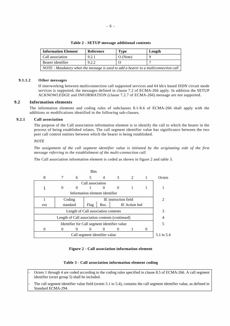
Table 2 - SETUP message additional contents
Information Element Reference Type LengthCall association 9.2.1 O (Note) 9
Bearer identifier 9.2.2 O 7
NOTE - Mandatory when the message is used to add a bearer to a multiconnection call
9.1.1.2 Other messages
If interworking between multiconnection call supported services and 64 kb/s based ISDN circuit modeservices is supported, the messages defined in clause 7.2 of ECMA-266 apply. In addition the SETUPACKNOWLEDGE and INFORMATION (clause 7.2.7 of ECMA-266) message are not supported.
9.2 Information elementsThe information elements and coding rules of subclauses 8.1-8.6 of ECMA-266 shall apply with theadditions or modifications identified in the following sub-clauses.
9.2.1 Call association
The purpose of the Call association information element is to identify the call to which the bearer in theprocess of being established relates. The call segment identifier value has significance between the twopeer call control entities between which the bearer is being established.
NOTE
The assignment of the call segment identifier value is initiated by the originating side of the firstmessage referring to the establishment of the multi-connection call.
The Call association information element is coded as shown in figure 2 and table 3.
Bits
8 7 6 5 4 3 2 1 Octets
Call association1 0 0 1 0 0 1 1 1
Information element identifier
1 Coding IE instruction field 2ext standard Flag Res. IE Action Ind
Length of Call association contents 3
Length of Call association contents (continued) 4
Identifier for Call segment identifier value 50 0 0 0 0 0 1 0
Call segment identifier value 5.1 to 5.4
Figure 2 - Call association information element
Table 3 - Call association information element coding
- Octets 1 through 4 are coded according to the coding rules specified in clause 8.5 of ECMA-266. A call segmentidentifier (octet group 5) shall be included.
- The call segment identifier value field (octets 5.1 to 5.4), contains the call segment identifier value, as defined inStandard ECMA-294.
- 7 -
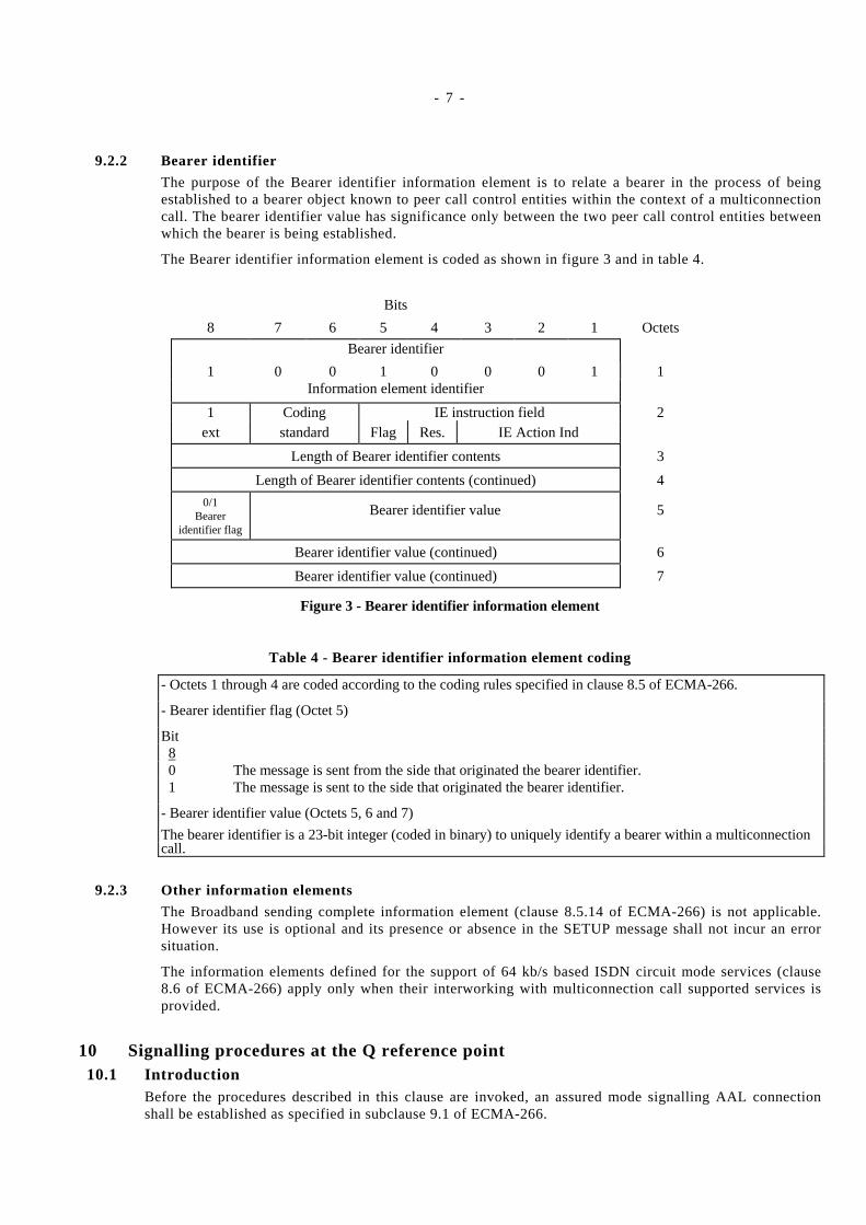
9.2.2 Bearer identifier
The purpose of the Bearer identifier information element is to relate a bearer in the process of beingestablished to a bearer object known to peer call control entities within the context of a multiconnectioncall. The bearer identifier value has significance only between the two peer call control entities betweenwhich the bearer is being established.
The Bearer identifier information element is coded as shown in figure 3 and in table 4.
Bits
8 7 6 5 4 3 2 1 Octets
Bearer identifier
1 0 0 1 0 0 0 1 1Information element identifier
1 Coding IE instruction field 2ext standard Flag Res. IE Action Ind
Length of Bearer identifier contents 3
Length of Bearer identifier contents (continued) 4
0/1Bearer
identifier flag
Bearer identifier value 5
Bearer identifier value (continued) 6
Bearer identifier value (continued) 7
Figure 3 - Bearer identifier information element
Table 4 - Bearer identifier information element coding
- Octets 1 through 4 are coded according to the coding rules specified in clause 8.5 of ECMA-266.
- Bearer identifier flag (Octet 5)
Bit 8 0 The message is sent from the side that originated the bearer identifier. 1 The message is sent to the side that originated the bearer identifier.
- Bearer identifier value (Octets 5, 6 and 7)
The bearer identifier is a 23-bit integer (coded in binary) to uniquely identify a bearer within a multiconnectioncall.
9.2.3 Other information elements
The Broadband sending complete information element (clause 8.5.14 of ECMA-266) is not applicable.However its use is optional and its presence or absence in the SETUP message shall not incur an errorsituation.
The information elements defined for the support of 64 kb/s based ISDN circuit mode services (clause8.6 of ECMA-266) apply only when their interworking with multiconnection call supported services isprovided.
10 Signalling procedures at the Q reference point10.1 Introduction
Before the procedures described in this clause are invoked, an assured mode signalling AAL connectionshall be established as specified in subclause 9.1 of ECMA-266.
- 8 -
The procedures specified in this clause cover the following capabilities:
a) addition of bearers to multiconnection call being established or having progressed to the active state,
b) release of bearers from an existing call, while maintaining the call active, including when no morebearers exist.
NOTE
Any of the users may initiate bearer establishment or clearing.
The procedures for basic (and simultaneous) call/connection control as defined in clause 9 of ECMA-266shall apply as the basis for the separated bearer control. Only additional procedures required to handle theseparated bearer control functions of a multiconnection call are described in the following subclauses.
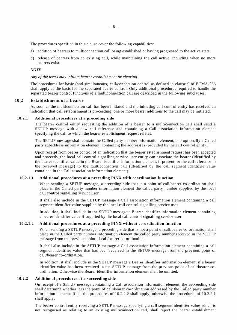
10.2 Establishment of a bearerAs soon as the multiconnection call has been initiated and the initiating call control entity has received anindication that call establishment is proceeding, one or more bearer additions to the call may be initiated.
10.2.1 Additional procedures at a preceding side
The bearer control entity requesting the addition of a bearer to a multiconnection call shall send aSETUP message with a new call reference and containing a Call association information elementspecifying the call to which the bearer establishment request relates.
The SETUP message shall contain the Called party number information element, and optionally a Calledparty subaddress information element, containing the address(es) provided by the call control entity.
Upon receipt from bearer control of an indication that the bearer establishment request has been acceptedand proceeds, the local call control signalling service user entity can associate the bearer (identified bythe bearer identifier value in the Bearer identifier information element, if present, or the call reference inthe received message) to the multiconnection call (identified by the call segment identifier valuecontained in the Call association information element).
10.2.1.1 Additional procedures at a preceding PINX with coordination function
When sending a SETUP message, a preceding side that is a point of call/bearer co-ordination shallplace in the Called party number information element the called party number supplied by the localcall control signalling service user.
It shall also include in the SETUP message a Call association information element containing a callsegment identifier value supplied by the local call control signalling service user.
In addition, it shall include in the SETUP message a Bearer identifier information element containinga bearer identifier value if supplied by the local call control signalling service user.
10.2.1.2 Additional procedures at a preceding PINX without co-ordination function
When sending a SETUP message, a preceding side that is not a point of call/bearer co-ordination shallplace in the Called party number information element the called party number received in the SETUPmessage from the previous point of call/bearer co-ordination.
It shall also include in the SETUP message a Call association information element containing a callsegment identifier value that has been received in the SETUP message from the previous point ofcall/bearer co-ordination.
In addition, it shall include in the SETUP message a Bearer identifier information element if a beareridentifier value has been received in the SETUP message from the previous point of call/bearer co-ordination. Otherwise the Bearer identifier information element shall be omitted.
10.2.2 Additional procedures at a succeeding side
On receipt of a SETUP message containing a Call association information element, the succeeding sideshall determine whether it is the point of call/bearer co-ordination addressed by the Called party numberinformation element. If so, the procedures of 10.2.2.2 shall apply, otherwise the procedures of 10.2.2.1shall apply.
The bearer control entity receiving a SETUP message specifying a call segment identifier value which isnot recognised as relating to an existing multiconnection call, shall reject the bearer establishment
- 9 -
request by sending a RELEASE COMPLETE message with cause #101, 'message not compatible withcall state'.
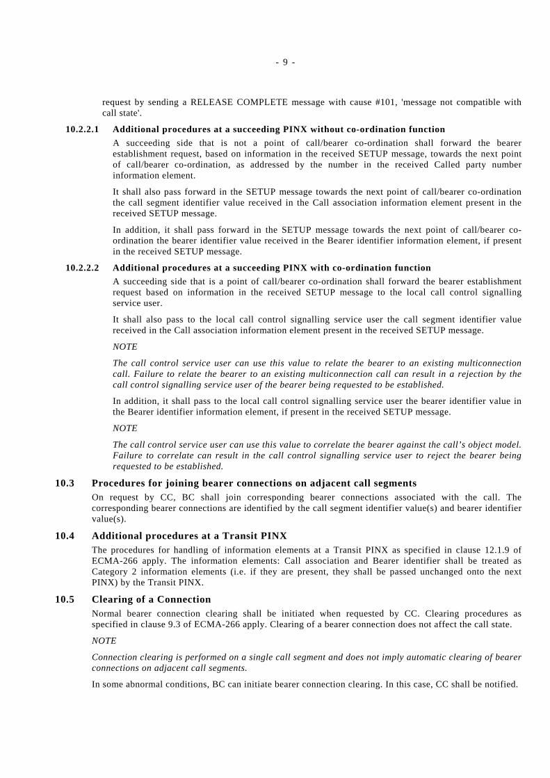
10.2.2.1 Additional procedures at a succeeding PINX without co-ordination function
A succeeding side that is not a point of call/bearer co-ordination shall forward the bearerestablishment request, based on information in the received SETUP message, towards the next pointof call/bearer co-ordination, as addressed by the number in the received Called party numberinformation element.
It shall also pass forward in the SETUP message towards the next point of call/bearer co-ordinationthe call segment identifier value received in the Call association information element present in thereceived SETUP message.
In addition, it shall pass forward in the SETUP message towards the next point of call/bearer co-ordination the bearer identifier value received in the Bearer identifier information element, if presentin the received SETUP message.
10.2.2.2 Additional procedures at a succeeding PINX with co-ordination function
A succeeding side that is a point of call/bearer co-ordination shall forward the bearer establishmentrequest based on information in the received SETUP message to the local call control signallingservice user.
It shall also pass to the local call control signalling service user the call segment identifier valuereceived in the Call association information element present in the received SETUP message.
NOTE
The call control service user can use this value to relate the bearer to an existing multiconnectioncall. Failure to relate the bearer to an existing multiconnection call can result in a rejection by thecall control signalling service user of the bearer being requested to be established.
In addition, it shall pass to the local call control signalling service user the bearer identifier value inthe Bearer identifier information element, if present in the received SETUP message.
NOTE
The call control service user can use this value to correlate the bearer against the call’s object model.Failure to correlate can result in the call control signalling service user to reject the bearer beingrequested to be established.
10.3 Procedures for joining bearer connections on adjacent call segmentsOn request by CC, BC shall join corresponding bearer connections associated with the call. Thecorresponding bearer connections are identified by the call segment identifier value(s) and bearer identifiervalue(s).
10.4 Additional procedures at a Transit PINXThe procedures for handling of information elements at a Transit PINX as specified in clause 12.1.9 ofECMA-266 apply. The information elements: Call association and Bearer identifier shall be treated asCategory 2 information elements (i.e. if they are present, they shall be passed unchanged onto the nextPINX) by the Transit PINX.
10.5 Clearing of a ConnectionNormal bearer connection clearing shall be initiated when requested by CC. Clearing procedures asspecified in clause 9.3 of ECMA-266 apply. Clearing of a bearer connection does not affect the call state.
NOTE
Connection clearing is performed on a single call segment and does not imply automatic clearing of bearerconnections on adjacent call segments.
In some abnormal conditions, BC can initiate bearer connection clearing. In this case, CC shall be notified.

- 10 -
11 Interworking with other networksInterworking occurs with other networks, which do not support the separation of call control and bearercontrol or which send simultaneous call and bearer establishment requests.
Interworking with such networks requires both call control and bearer control functions in the gateway nodeat the boundary to these networks.
For interworking with networks which do not support the separation of call control and bearer control, seesubclause C.1.1 to C.1.3 in annex C of ECMA-294.
For interworking with networks that supports only simultaneous call and bearer establishment, see subclauseC.2.2 and C.2.3 in annex C of ECMA-294.
12 Interworking with supplementary servicesBeyond the scope of the present Standard.
13 Parameter valuesNo additional parameter required in addition to those defined in ECMA-266.
14 Dynamic description SDLsNone required beyond those in annex D of ECMA-266.
The messages SETUP ACKNOWLEDGE and INFORMATION are not supported in this Standard, so thetransitions associated with these messages are not applicable.

- 11 -
Annex A
(normative)
Protocol Implementation Conformance Statement (PICS) proforma
A.1 IntroductionA.1.1 Basic reference documents for PICS proforma specifications
General rules for the specification of PICS proforma are provided by ISO/IEC 9646-1. Detailed guidancefor the specification of PICS proforma is provided by ISO/IEC 9646-7; in particular the structure of a PICSproforma, the questions to be asked, the syntax and notation to be used and the semantics of the questionsand expected answers.
For a PICS proforma, specific acronyms and terms are used as defined in ISO/IEC 9646-1 orISO/IEC 9646-7, e.g.:
ICS Implementation Conformance Statement
ICS proforma Implementation Conformance Statement proforma
ICS (proforma) item A row in an ICS (proforma) table
PICS Protocol ICS
PICS proforma Protocol ICS proforma
status (value) An allowed entry in the status column for an item in an ICS proforma table
(support) answer An allowed entry in the support or supported values columns for an item in an ICSquestion
A.1.2 Copyright InformationUsers of this specification may freely reproduce the PICS proforma of this annex A so that it can be usedfor its intended purpose and may further publish the completed PICS.
A.1.3 Structure of this PICS proformaThis PICS proforma is subdivided into (sub-)clauses as follows:
Instructions (A.2)
Purpose of a PICS proforma (A.2.1)
Instructions for completing the PICS proforma (A.2.2)
Additional Information (A.2.3)
Exception Information (A.2.4)
Legend for the columns of the PICS proforma tables (A.2.5)
Legend for further indications of the PICS proforma tables (A.2.6)
Identification of the implementation (A.3), including:
Identification of the protocol for which this PICS applies (A.3.7)
Global statement of conformance (A.4)
Roles (A.5)
Major capabilities (A.6)
Subsidiary capabilities (A.7)

- 12 -
PDUs (A.8)
PDU parameters received by the succeeding side (A.9)
PDU parameters sent by the preceding side (A.10)
Timers (A.11)
Call states (A.12)
A.2 InstructionsA.2.1 Purpose of a PICS proforma
To evaluate conformance of a particular implementation, it is necessary to have a statement of whichcapabilities and options have been implemented for a given OSI specification. Such a statement is called anImplementation Conformance Statement (ICS).
For protocol specifications, this statement is called "Protocol Implementation Conformance Statement"(PICS). For the provision of this statement, a fixed format questionnaire called PICS proforma has to beused. A completed PICS proforma is the PICS for the implementation in question. It is an ICS (as definedin ISO/IEC 9646-7) for an implementation or system which claims to conform to a given specification.
The PICS can have a number of uses, including:
by the protocol implementor, as a check list for implementations to reduce the risk of unintended non-conformance, e.g. through oversight;
by the supplier and acquirer, or potential acquirer, of the implementation, as a detailed indication of thecapabilities of the implementation, stated relative to the common basis for understanding provided by theStandard's PICS proforma;
by the user or potential user of the implementation, as a basis for initially checking the possibility ofinterworking with another implementation - while interworking can never be guaranteed, failure tointerwork can often be predicted from incompatible PICS.
by a protocol tester, as the basis for selecting appropriate tests against which to assess the claim forconformance of the implementation.
The PICS proforma of this annex therefore reflect a compromise between these different requirements.
A.2.2 Instructions for completing the PICS proformaThe supplier of a protocol implementation which is claimed to conform to this Standard shall complete thefollowing Protocol Implementation Conformance Statement (PICS) proforma.
The PICS proforma is a fixed format questionnaire. The supplier of the implementation shall complete thisquestionnaire, in particular identify the implementation, complete the global statement of conformance, andprovide the answers in the rows of the tables in clauses A.5 - A.12. The structure of the tables is explainedin subclauses A.2.5 and A.2.6. For each row in each table, the supplier shall enter an explicit answer (i.e.by ticking the appropriate "yes", "no", or "N/A" in each of the support column boxes provided. Where asupport column box is left blank, or where it is marked "N/A" without any tick box, no answer is required.If a "prerequisite line" (see A.2.6 below) is used after a subclause heading or table title, and its predicate isfalse, no answer is required for the whole subclause or table, respectively.
A supplier may also provide - or be required to provide - further information, categorized as eitherAdditional Information or Exception Information. When present, each kind of further information is to beprovided in a further subclause of items labelled
"a.<i>" for additional information,
"x.<i>" for exceptional information
for cross-referencing purposes, where <i> is any unambiguous identification for the item (e.g., simply anumeral); there are no other restrictions on its format and presentation.
- 13 -
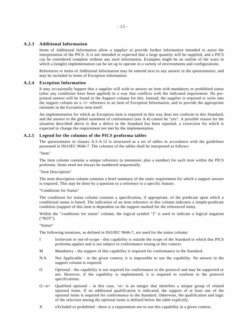
A.2.3 Additional InformationItems of Additional Information allow a supplier to provide further information intended to assist theinterpretation of the PICS. It is not intended or expected that a large quantity will be supplied, and a PICScan be considered complete without any such information. Examples might be an outline of the ways inwhich a (single) implementation can be set up to operate in a variety of environments and configurations.
References to items of Additional Information may be entered next to any answer in the questionnaire, andmay be included in items of Exception information.
A.2.4 Exception InformationIt may occasionally happen that a supplier will wish to answer an item with mandatory or prohibited status(after any conditions have been applied) in a way that conflicts with the indicated requirement. No pre-printed answer will be found in the Support column for this. Instead, the supplier is required to write intothe support column an x.<i> reference to an item of Exception Information, and to provide the appropriaterationale in the Exception item itself.
An implementation for which an Exception item is required in this way does not conform to this Standard;and the answer to the global statement of conformance (see A.4) cannot be "yes". A possible reason for thesituation described above is that a defect in the Standard has been reported, a correction for which isexpected to change the requirement not met by the implementation.
A.2.5 Legend for the columns of the PICS proforma tablesThe questionnaire in clauses A.5-A.12 is structured as a set of tables in accordance with the guidelinespresented in ISO/IEC 9646-7. The columns of the tables shall be interpreted as follows:
"Item"
The item column contains a unique reference (a mnemonic plus a number) for each item within the PICSproforma. Items need not always be numbered sequentially.
"Item Description"
The item description column contains a brief summary of the static requirement for which a support answeris required. This may be done by a question or a reference to a specific feature.
"Conditions for Status"
The conditions for status column contains a specification, if appropriate, of the predicate upon which aconditional status is based. The indication of an item reference in this column indicates a simple-predicatecondition (support of this item is dependent on the support marked for the referenced item).
Within the "conditions for status" column, the logical symbol "]" is used to indicate a logical negation("NOT").
"Status"
The following notations, as defined in ISO/IEC 9646-7, are used for the status column:
I Irrelevant or out-of-scope - this capability is outside the scope of the Standard to which this PICSproforma applies and is not subject to conformance testing in this context.
M Mandatory - the support of this capability is required for conformance to the Standard.
N/A Not Applicable - in the given context, it is impossible to use the capability. No answer in thesupport column is required.
O Optional - the capability is not required for conformance to the protocol and may be supported ornot. However, if the capability is implemented, it is required to conform to the protocolspecifications.
O.<n> Qualified optional - in this case, <n> is an integer that identifies a unique group of relatedoptional items. If no additional qualification is indicated, the support of at least one of theoptional items is required for conformance to the Standard. Otherwise, the qualification and logicof the selection among the optional items is defined below the table explicitly.
X eXcluded or prohibited - there is a requirement not to use this capability in a given context.
- 14 -
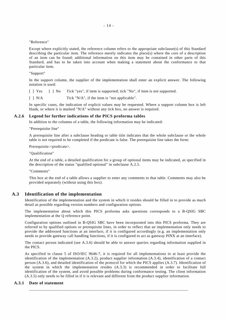
"Reference"
Except where explicitly stated, the reference column refers to the appropriate subclause(s) of this Standarddescribing the particular item. The reference merely indicates the place(s) where the core of a descriptionof an item can be found; additional information on this item may be contained in other parts of thisStandard, and has to be taken into account when making a statement about the conformance to thatparticular item.
"Support"
In the support column, the supplier of the implementation shall enter an explicit answer. The followingnotation is used:
[ ] Yes [ ] No Tick "yes", if item is supported; tick "No", if item is not supported.
[ ] N/A Tick "N/A", if the item is "not applicable".
In specific cases, the indication of explicit values may be requested. Where a support column box is leftblank, or where it is marked "N/A" without any tick box, no answer is required.
A.2.6 Legend for further indications of the PICS proforma tablesIn addition to the columns of a table, the following information may be indicated:
"Prerequisite line"
A prerequisite line after a subclause heading or table title indicates that the whole subclause or the wholetable is not required to be completed if the predicate is false. The prerequisite line takes the form:
Prerequisite:<predicate>.
"Qualification"
At the end of a table, a detailed qualification for a group of optional items may be indicated, as specified inthe description of the status "qualified optional" in subclause A.2.5.
"Comments"
This box at the end of a table allows a supplier to enter any comments to that table. Comments may also beprovided separately (without using this box).
A.3 Identification of the implementationIdentification of the implementation and the system in which it resides should be filled in to provide as muchdetail as possible regarding version numbers and configuration options.
The implementation about which this PICS proforma asks questions corresponds to a B-QSIG SBCimplementation at the Q reference point.
Configuration options outlined in B-QSIG SBC have been incorporated into this PICS proforma. They arereferred to by qualified options or prerequisite lines, in order to reflect that an implementation only needs toprovide the addressed functions at an interface, if it is configured accordingly (e.g. an implementation onlyneeds to provide gateway call handling functions, if it is configured to act as gateway PINX at an interface).
The contact person indicated (see A.3.6) should be able to answer queries regarding information supplied inthe PICS.
As specified in clause 5 of ISO/IEC 9646-7, it is required for all implementations to at least provide theidentification of the implementation (A.3.2), product supplier information (A.3.4), identification of a contactperson (A.3.6), and detailed identification of the protocol for which the PICS applies (A.3.7). Identification ofthe system in which the implementation resides (A.3.3) is recommended in order to facilitate fullidentification of the system, and avoid possible problems during conformance testing. The client information(A.3.5) only needs to be filled in if it is relevant and different from the product supplier information.
A.3.1 Date of statement___________________________________________________________________________________

- 15 -
A.3.2 Identification of the implementationThe terms "name" and "version" should be interpreted appropriately to correspond with a suppliersterminology (e.g. Type, Series, Model).
Name of the implementation:
___________________________________________________________________________________
___________________________________________________________________________________
Implementation version:
___________________________________________________________________________________
___________________________________________________________________________________
A.3.3 Identification of the system in which it residesName of the system:
___________________________________________________________________________________
___________________________________________________________________________________
Hardware configuration:
___________________________________________________________________________________
___________________________________________________________________________________
___________________________________________________________________________________
Operating system:
___________________________________________________________________________________
___________________________________________________________________________________
A.3.4 Product supplierName:
___________________________________________________________________________________
Address:
___________________________________________________________________________________
___________________________________________________________________________________
___________________________________________________________________________________
Telephone number:
___________________________________________________________________________________
Facsimile number:
___________________________________________________________________________________
E-Mail address:
___________________________________________________________________________________
Additional information:
___________________________________________________________________________________
___________________________________________________________________________________
___________________________________________________________________________________

- 16 -
A.3.5 ClientName:
___________________________________________________________________________________
Address:
___________________________________________________________________________________
___________________________________________________________________________________
___________________________________________________________________________________
Telephone number:
___________________________________________________________________________________
Facsimile number:
___________________________________________________________________________________
E-Mail address:
___________________________________________________________________________________
Additional information:
___________________________________________________________________________________
___________________________________________________________________________________
___________________________________________________________________________________
A.3.6 PICS contact personName:
___________________________________________________________________________________
Address:
___________________________________________________________________________________
___________________________________________________________________________________
___________________________________________________________________________________
Telephone number:
___________________________________________________________________________________
Facsimile number:
___________________________________________________________________________________
E-Mail address:
___________________________________________________________________________________
Additional information:
___________________________________________________________________________________
___________________________________________________________________________________
___________________________________________________________________________________

- 17 -
A.3.7 Protocol for which this PICS appliesProtocol:
B-QSIG-SBC - B-PISN inter-exchange signalling protocol – Separated bearer control
Protocol Version - please identify the standards document unambiguously, including e.g. reference number(ECMA-XXX), edition number (if applicable) and publication date:
___________________________________________________________________________________
___________________________________________________________________________________
Corrigenda Implemented (if applicable):
___________________________________________________________________________________
___________________________________________________________________________________
Addenda Implemented (if applicable):
___________________________________________________________________________________
___________________________________________________________________________________
Amendments Implemented (if applicable):
___________________________________________________________________________________
___________________________________________________________________________________
A.4 Global Statement of ConformanceDoes the implementation described in this PICS meet all the mandatory requirements of the referencedstandard:
[ ] Y e s
[ ] N o
NOTE A.1
Answering "No" to this question indicates non-conformance to the protocol specification. In this case, anexplanation shall be given of the nature of non-conformance either below or on a separate sheet of paper.Further the instructions outlined in subclause A.2.4 ("Exception Information") shall be followed whencompleting the PICS proforma tables.
Nature of non-conformance (if applicable):
___________________________________________________________________________________
___________________________________________________________________________________
___________________________________________________________________________________
___________________________________________________________________________________
___________________________________________________________________________________
___________________________________________________________________________________
___________________________________________________________________________________
___________________________________________________________________________________
___________________________________________________________________________________
___________________________________________________________________________________
___________________________________________________________________________________
___________________________________________________________________________________
___________________________________________________________________________________
- 18 -
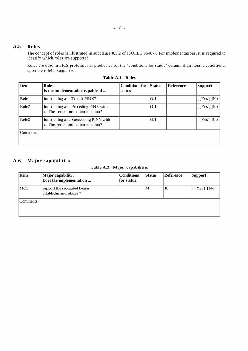
A.5 RolesThe concept of roles is illustrated in subclause 8.5.2 of ISO/IEC 9646-7. For implementations, it is required toidentify which roles are supported.
Roles are used in PICS proformas as predicates for the "conditions for status" column if an item is conditionalupon the role(s) supported.
Table A.1 - Roles
Item RolesIs the implementation capable of ...
Conditions forstatus
Status Reference Support
Role1 functioning as a Transit PINX? O.1 [ ]Yes [ ]No
Role2 functioning as a Preceding PINX withcall/bearer co-ordination function?
O.1 [ ]Yes [ ]No
Role3 functioning as a Succeeding PINX withcall/bearer co-ordination function?
O.1 [ ]Yes [ ]No
Comments:
A.6 Major capabilitiesTable A.2 - Major capabilities
Item Major capability:Does the implementation ...
Conditionsfor status
Status Reference Support
MC1 support the separated bearerestablishment/release ?
M 10 [ ] Yes [ ] No
Comments:

- 19 -
A.7 Subsidiary capabilitiesTable A.3 - Subsidiary capabilities
Item Subsidiary capabilityDoes the implementation...
Conditions forstatus
Status Reference Support
SC1 support procedures for bearer connectionestablishment at the preceding side?
Role1 ORRole2
] ( Role1 ORRole2)
M
N/A
10.2.1 [ ]Yes [ ]No
[ ]N/A
SC2 support procedures for bearer connectionestablishment at the succeeding side?
Role1 ORRole3
] (Role1 ORRole3)
M
N/A
10.2.2 [ ]Yes [ ]No
[ ]N/A
SC3 Support procedures for bearer connectionestablishment at the Transit PINX
Role1
] Role1
M
N/A
10.4 [ ]Yes [ ]No
[ ]N/A
SC4 Support procedures for joining bearerconnections on adjacent call segments
Role2 ORRole3
] (Role2 ORRole3)
M
N/A
10.3 [ ]Yes [ ]No
[ ]N/A
SC4 support connection clearing procedures M 10.5 [ ]Yes [ ]No
SC5 Support procedures for interworking withother networks not supporting separatedbearer control
Role2 ORRole3
] (Role2 ORRole3)
M
N/A
11 [ ]Yes [ ]No
[ ]N/A
Comments:
A.8 PDUsNo items requiring response.

- 20 -
A.9 PDU parameters received by the succeeding sideTable A.4 - Information elements in the SETUP message received by the succeeding side
Item SETUP message received by thesucceeding side:Does the implementation ...
Conditionsfor status
Status Reference Support
IES1 support the Call association informationelement (Note) ?
M 9.1.1.1 [ ] Yes [ ] No
IES2 support the Bearer identifier informationelement (Note) ?
M 9.1.1.1 [ ] Yes [ ] No
Note – Not applicable for the basic point-to-point combined call/bearer control protocol defined in ECMA-266.
Comments:
A.10 PDU parameters sent by the preceding sideTable A.5 - Information elements in the SETUP message sent by the preceding side
Item SETUP message sent by the precedingside:Does the implementation ...
Conditionsfor status
Status Reference Support
IEP1 support the Call association informationelement (Note) ?
M 9.1.1.1 [ ] Yes [ ] No
IEP2 support the Bearer identifier informationelement (Note) ?
M 9.1.1.1 [ ] Yes [ ] No
Note – Not applicable for the basic point-to-point combined call/bearer control protocol defined in ECMA-266.
Comments:
A.11 TimersNo items requiring response.
A.12 Call statesNo items requiring response.

- 21 -
Annex B
(informative)
Guidelines for the use of the instruction indicator
This annex provides guidelines for the setting of the instruction indicator field in the Call association andBearer identifier information elements. An implementation may choose to set the instruction indicatordifferently, depending on possible specific requirements beyond those covered explicitly within the presentStandard.
Recommended setting of the instruction indicator in the Call association information element:
Flag: "ignore explicit instructions"
Action indicator:"not significant".
Recommended setting of the instruction indicator in the Bearer identifier information element:
Flag: "ignore explicit instructions"
Action indicator:"not significant".


.

.

Free printed copies can be ordered from:ECMA114 Rue du RhôneCH-1204 GenevaSwitzerland
Fax: +41 22 849.60.01Email: [email protected]
Files of this Standard can be freely downloaded from the ECMA web site (www.ecma.ch). This site gives fullinformation on ECMA, ECMA activities, ECMA Standards and Technical Reports.

ECMA114 Rue du RhôneCH-1204 GenevaSwitzerland
See inside cover page for obtaining further soft or hard copies.