standard and safety technology in one system · standard and safety technology in one system ......
TRANSCRIPT

Bro
chu
re •
Ap
ril 2
00
7
SIMATIC Safety Integrated for Factory AutomationStandard and safety technology in one system
_Safety_4_FactoryAutomation.book Seite 1 Freitag, 13. April 2007 11:55 11
© Siemens AG 2007

2 Totally Integrated Automation
SIMATHuma
SIMATIC ControllersModular/Embedded/ PC-based
ERP – Enterprise Resource Planning
MES – Manufacturing Execution Systems
Ethernet
Ethernet
TotallyIntegratedAutomation
Control Level
SIMOTIONMotion Control System
Operations Level
Field Level
Management Level
SIMATIC PCS 7Process Control (DCS)
SINUMERIKComputer Numeric Control
• Maintenance• Modernization and Upgrade
Industrial Software for• Design and Engineering• Installation and Commissioning• Operation
SIMATIC NETIndustrialCommunication
PROFIBUS PA
SIMATIC Distributed I/OSIMATIC Sensors SINProcess Instrumentation
HART
AS-Interface
SIMATIC IT
Increase your competitiveness with Totally Integrated Automation
To be able to respond to the increasing international com-petitive pressure, it is more important than ever that you focus on the core competencies of your company. The me-dium-term and long-term strategic focus on innovative au-tomation concepts will be a key factor that helps you achieve sustained success.
With Totally Integrated Automation (TIA), Siemens offers the perfect basis for this - for all sectors, from goods receipt to goods dispatch. Thanks to the unique integration of Totally Integrated Automation you can benefit from the outstanding interaction of all of our products and systems - even different versions. Thus you protect your investments and simulta-neously take advantage of future developments.
_Safety_4_FactoryAutomation.book Seite 2 Freitag, 13. April 2007 11:55 11
© Siemens AG 2007
Totally Integrated Automation 3
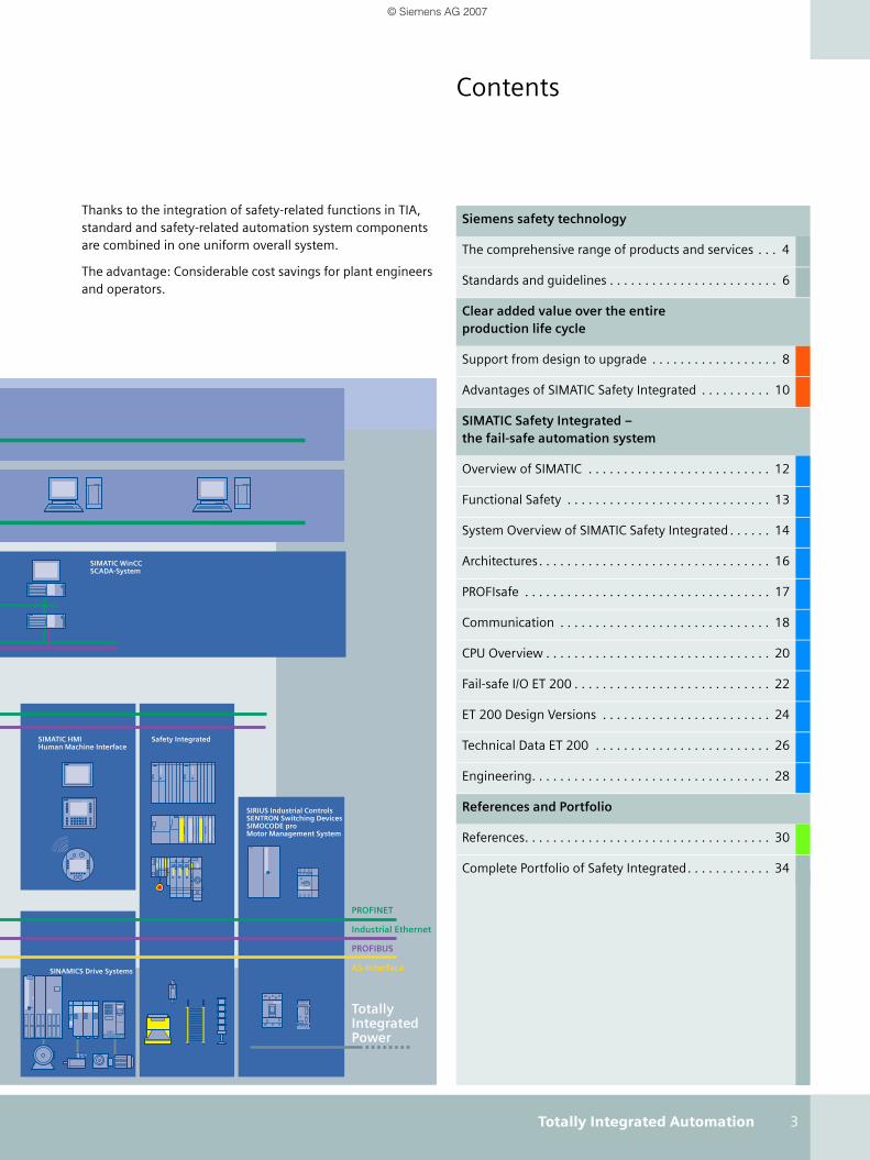
Contents
Thanks to the integration of safety-related functions in TIA, standard and safety-related automation system components are combined in one uniform overall system.
The advantage: Considerable cost savings for plant engineers and operators.
Siemens safety technology
The comprehensive range of products and services . . . 4
Standards and guidelines . . . . . . . . . . . . . . . . . . . . . . . . 6
Clear added value over the entire production life cycle
Support from design to upgrade . . . . . . . . . . . . . . . . . . 8
Advantages of SIMATIC Safety Integrated . . . . . . . . . . 10
SIMATIC Safety Integrated – the fail-safe automation system
Overview of SIMATIC . . . . . . . . . . . . . . . . . . . . . . . . . . 12
Functional Safety . . . . . . . . . . . . . . . . . . . . . . . . . . . . . 13
System Overview of SIMATIC Safety Integrated . . . . . . 14
Architectures. . . . . . . . . . . . . . . . . . . . . . . . . . . . . . . . . 16
PROFIsafe . . . . . . . . . . . . . . . . . . . . . . . . . . . . . . . . . . . 17
Communication . . . . . . . . . . . . . . . . . . . . . . . . . . . . . . 18
CPU Overview . . . . . . . . . . . . . . . . . . . . . . . . . . . . . . . . 20
Fail-safe I/O ET 200 . . . . . . . . . . . . . . . . . . . . . . . . . . . . 22
ET 200 Design Versions . . . . . . . . . . . . . . . . . . . . . . . . 24
Technical Data ET 200 . . . . . . . . . . . . . . . . . . . . . . . . . 26
Engineering. . . . . . . . . . . . . . . . . . . . . . . . . . . . . . . . . . 28
References and Portfolio
References. . . . . . . . . . . . . . . . . . . . . . . . . . . . . . . . . . . 30
Complete Portfolio of Safety Integrated. . . . . . . . . . . . 34
Safety IntegratedSIMATIC HMIHuman Machine Interface-based
TotallyIntegratedPower
SIRIUS Industrial ControlsSENTRON Switching DevicesSIMOCODE proMotor Management System
SIMATIC WinCCSCADA-System
AS-Interface
PROFIBUS
PROFINET
Industrial Ethernet
SINAMICS Drive Systems
_Safety_4_FactoryAutomation.book Seite 3 Freitag, 13. April 2007 11:55 11
© Siemens AG 2007

4 Siemens safety technology
Safety Integrated for Factory Automation –the comprehensive range of products and services
The integrity of man, machine and the environment de-pends on the fault-free functioning of the automated sys-tems in use.
For this reason, safety-relevant tasks are increasingly trans-ferred to automation components. As the technology leader in this field, Siemens recognized this trend, took it on and consis-tently implemented it from very early on.
Totally Integrated Automation –The basis for customer-specific automation solutions
With Totally Integrated Automation (TIA), Siemens is the only supplier of a comprehensive, integrated range of products and systems for implementing customer-specific automation solu-tions. Standard and safety-oriented automation merge into an integrated overall system through the integration of safety functions into the world of TIA. The advantage: Clear cost sav-ings for machine manufacturers and system operators.
Siemens, the complete supplier of safety technology – Safety Integrated
Product and solution portfolio...As the technology leader in safety technology, Siemens is con-stantly the driving force behind progress in this field, just as it has been for more than 20 years. Safety Integrated is the con-sistent implementation of safety technology in terms of Totally Integrated Automation: A unique, complete and integrated safety program from a single source.
Our contribution to this is: Safety Integrated – the most com-plete safety technology product and service portfolio currently on the market. Developed further on the basis of Totally Inte-grated Automation, it not only provides maximum reliability and performance capability in all safety applications, but also provides potential savings along the entire line.
... rounded off by competent lifecycle support Siemens provides you with much more than a complete range of products and systems for safety technology. As your part-ner, we will provide you with competent support during all phases of the production life cycle, from the risk analysis and corresponding training package to the acceptance of your machine.
The advantages for you are obvious: Our consulting will help you explore new markets, reduce your costs resulting from wrong actions, optimize your conformance to schedules and increase the product and process quality.
In addition, the test reports from an independent, accredited test center guarantee unambiguous safety certificates.
In other words: You can depend on our support one hundred percent – around the clock. Because our contact persons are at your disposal worldwide, 24 hours a day (see also Safety Inte-grated brochure, E20001-A150-M103).
SIMATIC Safety Integrated
Continuously increasing requirements... Compared to past solutions, industrial automation is now con-siderably more flexible and open. Modern machines and sys-tems also stand out due to their significantly increased pro-ductivity. This is due in no small part to the fact the relay tech-nology has been replaced by the freely programmable control-ler and decentralization – at least for demanding applications.
In spite of this change in technology, very different products and systems were often used until now for safety-oriented functions and standard tasks. If more complex safety tasks are involved however, the efficiency of an automation solution can be significantly increased even if the safety technology consistently follows the trend toward intelligent PLCs.
A fail-safe PLC serves to control processes and immediately switches to a safer state or remains in the current state if a fault occurs. It provides an integrated, efficient safety solution in systems with increased safety requirements.
Global deliveryservice
Training
Technicalconsultants Documentation
Engineering viasolution partners
Risk analysis
Onlineinformation
Complete product portfolio
Integrationin standardautomation
Consistency
Complete offer of Safety Integrated
Siemens safety technology
_Safety_4_FactoryAutomation.book Seite 4 Freitag, 13. April 2007 11:55 11
© Siemens AG 2007

Siemens safety technology 5
… and our answer to thisThe range of SIMATIC Safety Integrated products encompasses safety-oriented control systems for the process and manufac-turing industry, based on the SIMATIC S7-300 and S7-400 CPUs and SIMATIC ET 200.
SIMATIC Safety Integrated is presented in the following for the manufacturing industry. The Safety Integrated for Process Automation (E86060-A4678-A181-A1) brochure describes safety solutions for the process industry.
SIMATIC Safety Integrated includes a scalable range of safety-related controllers for all areas of factory automation – from ET 200S over S7-300 to S7-400.
Depending on your specific requirements, you can integrate the safety technology into the standard automation (inte-grated system) or implement it by means of two separate sys-tems based on SIMATIC (one standard, one safety technology).
With this, we are providing you with an integrated, safe and proven control system, which is extremely flexible, easy to expand and cost-effective. This results in the creation of the standard and safety program with its proven S7 environment, which reduces the engineering costs and the training and instruction outlay.
Programming is done using the STEP 7 languages LAD and FBD and TÜV-certified function blocks.
CPUs SIMATIC Safety Integrated
The connection to the standard and safety-oriented modules can be optionally made via PROFINET, the open Ethernet stan-dard, or via PROFIBUS, the tried and tested fieldbus technol-ogy. The bus system is expanded by the PROFIsafe profile for transmitting the safety-oriented data. Safety-related and stan-dard communication are now possible over only one standard bus cable.
Compliance with all major standards
The European guidelines apply today as those that reflect the highest safety standard and are accepted far beyond the boundaries of Europe.
In order to ensure the functional safety of a machine or sys-tem, the safety-relevant parts of the protective and control sys-tems behave in such a manner in the event of a fault that the system remains in a safe state or is put into a safe state. To this end, special requirements that are defined in standards are placed on the products. Corresponding product certificates can document the compliance with these standards.
Any possible hazards to people and the environment cannot just be averted at the national level. They must always comply with the regulations and rules of the location where the machine or system is operated. Thus the free exchange of goods within the framework of global markets requires inter-nationally agreed codes of practice.
The current standards are fulfilled when you use SIMATIC Safety Integrated. Because all of the safety-related compo-nents from the SIMATIC Safety Integrated range of products achieve the maximum safety level:
■ IEC 61508: 2000 SIL 1 - 3
■ EN 594-1 : 1997 Cat. 2 - 4
■ IEC 61511: 2003
■ EN 60204-1 : 1997
■ IEC 62061: 2005
■ NFPA 79-2002, NFPA 85
■ TÜV certificate no.: Z10 05 08 20411 002
■ UL 1998, UL 508 and UL 991
_Safety_4_FactoryAutomation.book Seite 5 Freitag, 13. April 2007 11:55 11
© Siemens AG 2007
6 Siemens safety technology
Fundamental safety requirements in the production industry
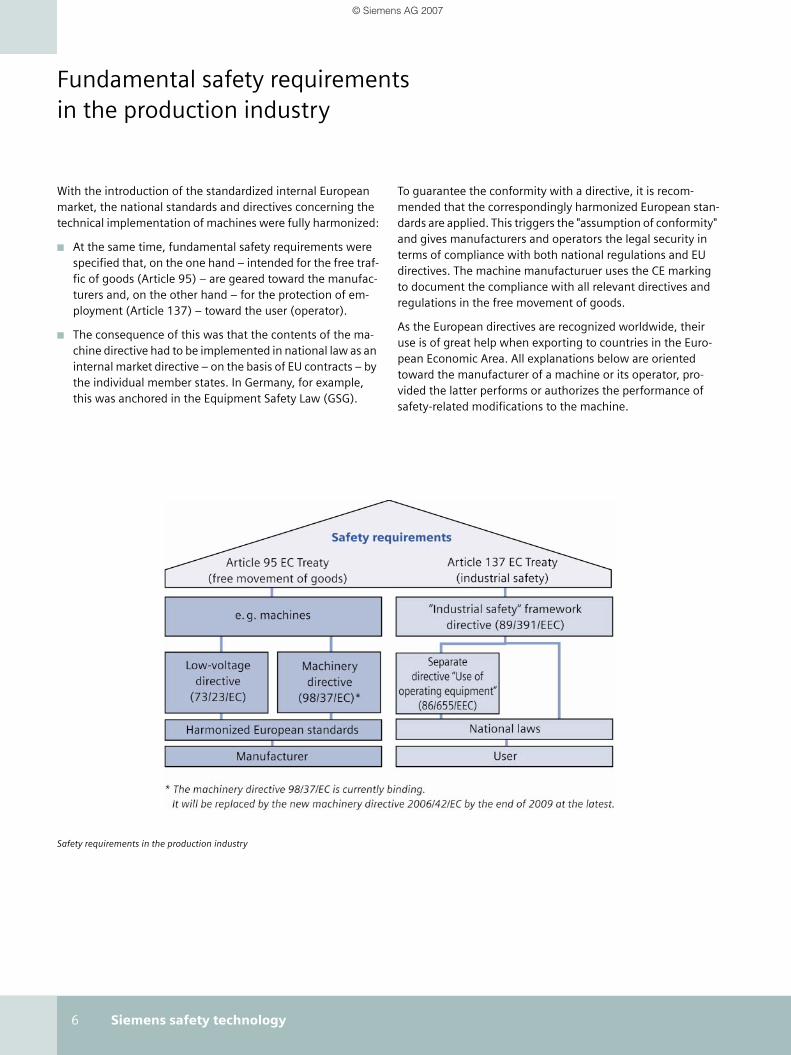
With the introduction of the standardized internal European market, the national standards and directives concerning the technical implementation of machines were fully harmonized:
■ At the same time, fundamental safety requirements were specified that, on the one hand – intended for the free traf-fic of goods (Article 95) – are geared toward the manufac-turers and, on the other hand – for the protection of em-ployment (Article 137) – toward the user (operator).
■ The consequence of this was that the contents of the ma-chine directive had to be implemented in national law as an internal market directive – on the basis of EU contracts – by the individual member states. In Germany, for example, this was anchored in the Equipment Safety Law (GSG).
To guarantee the conformity with a directive, it is recom-mended that the correspondingly harmonized European stan-dards are applied. This triggers the "assumption of conformity" and gives manufacturers and operators the legal security in terms of compliance with both national regulations and EU directives. The machine manufacturuer uses the CE marking to document the compliance with all relevant directives and regulations in the free movement of goods.
As the European directives are recognized worldwide, their use is of great help when exporting to countries in the Euro-pean Economic Area. All explanations below are oriented toward the manufacturer of a machine or its operator, pro-vided the latter performs or authorizes the performance of safety-related modifications to the machine.
Safety requirements in the production industry
_Safety_4_FactoryAutomation.book Seite 6 Freitag, 13. April 2007 11:55 11
© Siemens AG 2007

Siemens safety technology 7
Fundamental standards in the drafting of control functions
Safety requires protection against a variety of risks. These can be overcome as follows:
■ Design in accordance with risk-reducing design principles and risk assessment of the machine (EN ISO 12100-1, EN 1050)
■ Technical protection measures, if necessary by the use of safety-related controllers (functional safety in accordance with EN 62061 or EN ISO 13849-1)
■ Electrical safety (EN 60204-1)
Functional safety involves the part of the safety of a machine or plant that depends on the correct function of its control or protection equipment. Two standards are available to the user:
■ EN 62061:2005 – as European sector standard of the basic standard IEC 61508.
■ EN ISO 13849-1:2006 – as revised successor standard to the EN 954-1, as this is no longer adequate with reference to these categories.
Objective:Compliance with all relevant safety require-ments by means of adequate reduction of risk – with the aim of being secure against liability and "export-ready".
Result:Implementation of risk-reducing measures by applying harmonized standards – resulting in conformity with the safety requirements of the machine directive on the basis of the "assump-tion of conformity."
Standards for the drafting of controllers
_Safety_4_FactoryAutomation.book Seite 7 Freitag, 13. April 2007 11:55 11
© Siemens AG 2007

8 Clear added value over the entire production life cycle
Clear added value – throughout the entire product life cycle
With our innovative and extensive range of products for safety technology and our competent support, we offer you clear advantages – through every phase of the product life cycle.
Support from design to upgrade
Clear added value over the entire production life cy-
Phase Requirement
Before creating a machine, the machine manufacturer carries out a risk analysis being sure to observe all of the relevant standards. This shows what risks the machine poses and how they must be coun-tered.
The risk analysis reveals which components are needed for making the hazardous zones safe. The safety must be verified, so that the machine receives its CE marking.
The operator must observe the occupational safety framework guidelines – as well as the documentation for following the machine directive that the machine manufacturer has to produce.
If maintenance is required, it must be performed quickly, in order to keep downtimes and standstills as short as possible. If a fault does occur, it must be cleared as quickly as possible. Because, for compet-itive reasons it is essential to keep production up and running with only brief interruptions.
In order to bring existing plants up to the state of the art of safety engineering, expansion or modernization measures are necessary. Through inspections, documentation, consulting and defining remedial measures, we assist you in meeting the current safety requirements most effectively.
Design and engineering
Installation and startup
Operation
Maintenance
Modernization and upgrade
_Safety_4_FactoryAutomation.book Seite 8 Freitag, 13. April 2007 11:55 11
© Siemens AG 2007

Clear added value over the entire production life cycle 9
Safety Plan – the guideline when implementing a safe machine
The Safety Plan, whose structure and obligatory implementa-tion is defined in standard EN 62061, supports you in deter-mining and implementing all safety-related aspects and regu-lations for the design and operation of a safe machine – through every phase of the product life cycle.
Due to the systematic procedure presented by the Safety Plan you not only achieve the highest level of safety, but save con-siderable time at every stage – even in the CE marking of the machines.
Services System advantages
■ Conducting the risk analysis
■ Comprehensive training package
■ Support in planning and design
■ Advice for the application/design of safety-relevant directives and standards
■ Fewer interfaces: all system components from one source and a comprehensive range of services
■ Fewer interfaces: all system components and a comprehensive range of services from one source
■ Saving of time and money through safety integrated into the stan-dard engineering
■ New solution approaches through innovative technologies
■ Products and systems for worldwide use with the required approvals and conformity with the EU directives
■ Support during the machine acceptance or hand-over by provid-ing proof of conformity.
■ International approval
■ The setup saves space, time and costs through the integration of safety automation into the standard automation
■ Quick commissioning through comprehensive diagnostics and pre-wired and certified components - expertise in product liability
■ Global presence due to on-site service
■ Fast delivery of spare parts for a small capital commitment
■ TÜV-compliant user manuals
■ Quick fault diagnostics and fault clearing thanks to universality raises productivity
■ Standardized operating philosophy simplifies handling
■ High production quality and availability reduces downtimes
■ Global presence due to on-site service
■ Fast delivery of spare parts for a small capital commitment
■ Quick fault diagnostics and fault clearing thanks to universality of Safety Integrated
■ Reduced spare parts management and low capital commitment, because numerous components can be used for standard and safety applications.
■ Long-term availability of the components
■ Risk analysis
■ Support in implementation, conforming to your requirements and the latest status of safety technology
■ Modular system concepts
■ Fewer interfaces: all system components from one source and a comprehensive range of services
■ Comprehensive training package
■ Simple expansion through integration into the world of Totally In-tegrated Automation
■ Long-term product availability
■ Modular system concepts
_Safety_4_FactoryAutomation.book Seite 9 Freitag, 13. April 2007 11:55 11
© Siemens AG 2007

10 Clear added value over the entire production life cycle
Design and engineering
ServiceAs early as the planning phase, we take the concrete requirements of the EU directives and the require-
ments for worldwide approval into consideration.
We offer a comprehensive training package – for example including the following topics: The use of various standards, programming the devices for standardization and safety or the use of user-friendly functions such as connecting safety-ori-ented drives.
System advantagesThe tried and tested system environment of SIMATIC really pays off: Users profit from significant savings in both time and costs. Existing expertise in standard engineering carries over into safety engineering. The integrated engineering in STEP 7 makes it possible to work in a traditional developmental envi-ronment. No costly retraining of employees is necessary. Thanks to the certified program module library, safety func-tions can be quickly implemented.
A shared database for fail-safe and standard applications pro-vides integrated data and project management.
The system is open due to the use of standards such as PROFI-BUS and PROFINET with PROFIsafe. Siemens provides new solution approaches through the use of innovative technology such as wireless.
Installation and startup
ServicesWe provide support during the machine acceptance or hand-over by providing proof of conformity. Thanks to
our contacts with worldwide certification centers such as UL, SA, etc., we are in a position to obtain international certificates for your machine or system.
System advantagesYou will save time during set up through the use of only one bus system for standard and safety applications. In addition, the number of hardware components needed is reduced thanks to the integration of safety technology into the stan-dard technology. The result: More space in the control cabinet. And last but not least, you will profit from the increased flexi-bility of the automation solution.
Comprehensive diagnostic capabilities and pre-wired and cer-tified components accelerate the commissioning. Pre-calcu-lated safety distances (e.g. the distance of light barriers to the part presenting the hazard) in the engineering phase mini-mize the risk of reworking in the construction phase.
Advantages of SIMATIC Safety Integrated
_Safety_4_FactoryAutomation.book Seite 10 Freitag, 13. April 2007 11:55 11
© Siemens AG 2007
Clear added value over the entire production life cycle 11
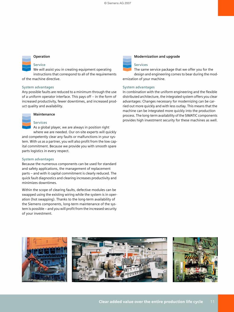
Operation
ServiceWe will assist you in creating equipment operating instructions that correspond to all of the requirements
of the machine directive.
System advantagesAny possible faults are reduced to a minimum through the use of a uniform operator interface. This pays off – in the form of increased productivity, fewer downtimes, and increased prod-uct quality and availability.
Maintenance
ServicesAs a global player, we are always in position right where we are needed. Our on-site experts will quickly
and competently clear any faults or malfunctions in your sys-tem. With us as a partner, you will also profit from the low cap-ital commitment. Because we provide you with smooth spare parts logistics in every respect.
System advantagesBecause the numerous components can be used for standard and safety applications, the management of replacement parts – and with it capital commitment is clearly reduced. The quick fault diagnostics and clearing increases productivity and minimizes downtimes.
Within the scope of clearing faults, defective modules can be swapped using the existing wiring while the system is in oper-ation (hot swapping). Thanks to the long-term availability of the Siemens components, long-term maintenance of the sys-tem is possible – and you will profit from the increased security of your investment.
Modernization and upgrade
ServicesThe same service package that we offer you for the design and engineering comes to bear during the mod-
ernization of your machine.
System advantagesIn combination with the uniform engineering and the flexible distributed architecture, the integrated system offers you clear advantages: Changes necessary for modernizing can be car-ried out more quickly and with less outlay. This means that the machine can be integrated more quickly into the production process. The long-term availability of the SIMATIC components provides high investment security for these machines as well.
_Safety_4_FactoryAutomation.book Seite 11 Freitag, 13. April 2007 11:55 11
© Siemens AG 2007

12 SIMATIC Safety Integrated – the fail-safe automation system
SIMATIC overview
For more than 30 years, the name SIMATIC stands for first-class automation technology. Today, SIMATIC is established worldwide and is rightly regarded as the number one.
As the heart of Totally Integrated Automation, SIMATIC encompasses a number of standardized products and systems that serve as the basis for implementing customer-specific solutions in all sectors. The core products are the programma-ble S7 controllers in both the centralized and distributed con-figuration.
SIMATIC S7-300 and S7-400 are the two best-selling control-lers worldwide. Countless successful reference applications from the most diverse sectors of industry impressively prove their quality and efficiency.
SIMATIC S7-300
The S7-300 is the modular controller for system solutions in the manufacturing industry:
■ Compact design, mounting on DIN rail
■ Many functions are integrated into the CPU (I/Os, technol-ogy functions, PROFIBUS/PROFINET connection)
■ Maintenance-free thanks to data retentivity on Micro Memory Card
■ Isochronous mode on PROFIBUS
■ Fail-safe versions
SIMATIC S7-400
The S7-400 is the power controller for system solutions in the manufacturing and processing industry:
■ Rack system with various rack types
■ Extremely high-speed processing and communication per-formance
■ Changes to the configuration during operation
■ Isochronous mode on PROFIBUS
■ Fail-safe and fault-tolerant versions
■ Hot swapping
SIMATIC ET 200
With SIMATIC ET 200 a wide range of distributed I/O systems is available – for solutions in the control cabinet, without a con-trol cabinet directly at the machine and for applications in explosion hazard areas.
The following ET 200 systems allow a hybrid installation with standard and fail-safe modules:
■ SIMATIC ET 200S - The all-rounder with a comprehensive range of functions
■ SIMATIC ET 200M – The multi-channel S7-300
■ SIMATIC ET 200pro - modular and multifunctional
■ SIMATIC ET 200eco - digital block I/O
SIMATIC Safety Integrated – the fail-safe automation system
Production automation using ...S7-300... ...S7-400 and... ...ET 200S
_Safety_4_FactoryAutomation.book Seite 12 Freitag, 13. April 2007 11:55 11
© Siemens AG 2007

SIMATIC Safety Integrated – the fail-safe automation system 13
Ensuring functional safety
A safety-oriented system encompasses sensors for signal acquisition, a processing unit for processing the signals and actuators for signal output.
Processing chain: acquire, process, output
All of the components contribute to the functional safety of the system in order to put the system into a safe state in the event of a dangerous situation or to keep it in a safe state.
Safety using SIMATIC Safety Integrated
For SIMATIC Safety Integrated systems, the evaluation unit consists of fail-safe single-channel CPUs and fail-safe dual-channel I/O modules. The fail-safe communication takes place via the safety-oriented PROFIsafe profile.
SIMATIC Safety Integrated is certified according to
■ IEC 61508: 2000 SIL 1 - 3
■ EN 594-1 : 1997 Cat. 2 - 4
■ IEC 61511: 2003
■ EN 60204-1 : 1997
■ IEC 62061: 2005
■ NFPA 79-2002, NFPA 85
and thus fulfills the highest requirements for the manufactur-ing and processing industry.
Fail-safe CPUs
The fail-safe CPUs have the following functions:
■ Comprehensive self-tests and self-diagnostics check the fail-safe state of the CPU.
■ Simultaneous execution of standard and safety programs on one CPU.
Fail-safe I/O modules (F modules)
The major difference between fail-safe modules and standard ET 200 modules is that fail-safe modules have a two-channel internal design. Both integrated processors monitor each other and automatically test the input and output wiring, and place the F-module in a safe state in the event of a fault.
The F-CPU communicates with the fail-safe module via the PROFIsafe safety-related bus profile.
Fail-safe power modules supply load voltage to the potential group and safely shut down the load voltage for standard out-put modules.
Fail-safe digital input modules record the signal states of safety-related sensors (e.g. emergency stop pushbutton) and send corresponding safety message frames to the F-CPU. Fail-safe digital output modules are suitable for switching pro-cesses with short-circuit monitoring up to the actuator.
Sensor Processing unit Actuator
Functional safety
_Safety_4_FactoryAutomation.book Seite 13 Freitag, 13. April 2007 11:55 11
© Siemens AG 2007

14 SIMATIC Safety Integrated – the fail-safe automation system
SIMATIC Safety Integrated - System Overview
With SIMATIC Safety Integrated, Siemens offers an exhaus-tive fail-safe product range that is based on the SIMATIC S7-300 and S7-400 automation systems.
SIMATIC Safety IntegratedProduct range for the manufacturing industry
Communication Safety-related communication is possible by means of the PROFIsafe pro-file. Standard and safety-related communication can take place over one and the same bus cable – be it PROFIBUS or PROFINET.
Controllers Fail-safe CPUs allow simultaneous processing of standard and safety pro-grams. The spectrum covers CPUs of most varying performance ranges:
■ ET 200S: On-site intelligence in the lower performance range
■ S7-300: Medium and upper performance range
■ S7-400: The top performance range
I/O Distributed field devices from the ET 200 range are used as I/O. There are control cabinet models, or with a high degree of protection for cabinet-less use - in modular as well as block design:
Engineering Fail-safe systems are configured using STEP 7 and S7 Distributed Safety. Standard languages LAD and FBD, as well pre-fabricated, certified com-ponents are used for programming the safety programs.
■ ET 200S
■ ET 200M
■ ET 200pro
■ ET 200eco
_Safety_4_FactoryAutomation.book Seite 14 Freitag, 13. April 2007 11:55 11
© Siemens AG 2007

SIMATIC Safety Integrated – the fail-safe automation system 15
1) with CP 443-1 Advanced
Fail-safe controller and ET 200 systems
SIMATIC Controllerfor fail-safe solutions
Controllers PROFIBUS PROFINET
ET 200S IM 151-7 F-CPU ■
S7-300 CPU 315F-2 DP ■
CPU 315F-2 PN/DP ■ ■
CPU 317F-2 DP ■
CPU 317F-2 PN/DP ■ ■
CPU 319F-3 PN/DP ■ ■
S7-400 CPU 416F-2 ■ ■ 1)
CPU 416F-3 PN/DP ■ ■
SIMATIC I/O systemsfor fail-safe solutions
I/O
sy
ste
m
De
gre
e o
f p
rote
ctio
n
PR
OFI
BU
S
PR
OFI
NE
T
DI
DO
Re
lays
DI/
DO
AI
Mo
tor
sta
rte
r
Fre
q. c
on
v.
ET 200S IP20 ■ ■ ■ ■ ■ ■ ■
ET 200M IP20 ■ ■ ■ ■
ET 200pro IP65/67 ■ ■ ■ ■ ■ ■
ET 200eco IP65/67 ■ ■
_Safety_4_FactoryAutomation.book Seite 15 Freitag, 13. April 2007 11:55 11
© Siemens AG 2007

16 SIMATIC Safety Integrated – the fail-safe automation system
Architectures
Fail-safe applications can be implemented in various forms. A distinction is made between four different options.
Separation of PLC, I/O and bus
In this configuration, completely separated systems are avail-able for the standard section and the safety section (a very widespread solution today).
Separation of PLC, I/O and bus
One bus, but separation of PLC and I/Os
In this configuration, separate controllers and separate I/Os are available for the standard section and safety section. Com-munication is carried out via a shared bus system.
One bus, but separation of PLC and I/Os
One PLC, but separation of I/Os and bus
In this configuration, there is a shared controller, but separate bus systems and separate I/Os for the standard section and safety section.
One PLC, but separation of I/Os and bus
One PLC, one bus and hybrid I/Os
In this configuration, a shared controller, a shared bus system and shared I/Os serve both the standard section and the safety section.
One PLC, one bus and hybrid I/Os
PLC level
I/O level
PLC level
I/O level
PLC level
I/O level
PLC level
I/O level
_Safety_4_FactoryAutomation.book Seite 16 Freitag, 13. April 2007 11:55 11
© Siemens AG 2007

SIMATIC Safety Integrated – the fail-safe automation system 17
Safety-related communication with the PROFIsafe profile on a shared bus line
PROFIsafe was the first communication standard to safety standard IEC 61508 that permits both standard and safety-related communication on one bus line. This not only results in an enormous savings potential with regard to cabling and the required number of parts, but also the advantage of retro-fitting.
PROFIsafe is an open solution with safety-related communica-tion via standard fieldbuses. Numerous manufacturers of fail-safe components and end users of safety technology have helped develop this vendor-independent and open standard for PROFIBUS International (PI).
PROFIsafe profile allow safe communication for the open stan-dard buses PROFIBUS and PROFINET on the basis of standard network components. In connection with PROFINET, PROFIsafe also supports fail-safe wireless communication via IWLAN.
The table below shows how PROFIsafe deals with the various potential sources of errors when transmitting messages.
Safety-related and standard data is transferred using PROFIsafe via the same bus line. The black channel indicates that safety-related communication is inde-pendent of the bus system and the underlying network components.
PROFIsafelayer
PROFIsafelayer
Standardbus protocol
Standardbus protocol
Fail-safedata
Standarddata
Fail-safedata
Standarddata
PROFINET
PROFIBUSor „B
lack
ch
ann
el“
PROFIsafe
PROFIsafeMeasures against transmission errors
MeasureFault
Consecutive number
Time expecta-tion with acknowledg-ment
Identification for transmitter and receiver
Data security CRC
Repeat ■
Loss ■ ■
Insertion ■ ■ ■
Incorrect sequence ■
Data corruption ■
Delay ■
Coupling of safety-related messages and stan-dard messages (masquerade)
■ ■ ■
FIFO errors (First In First Out data register for maintaining the sequence)
■
_Safety_4_FactoryAutomation.book Seite 17 Freitag, 13. April 2007 11:55 11
© Siemens AG 2007
18 SIMATIC Safety Integrated – the fail-safe automation system
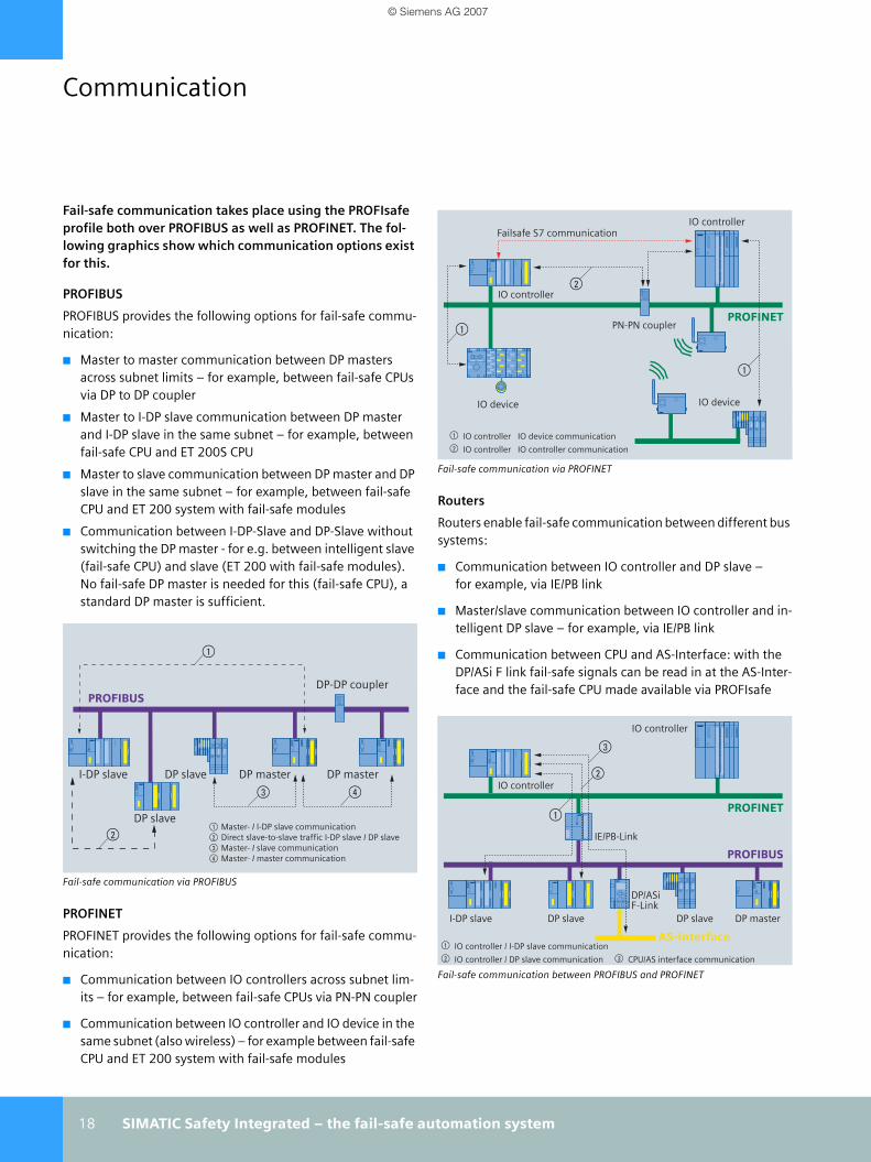
Fail-safe communication takes place using the PROFIsafe profile both over PROFIBUS as well as PROFINET. The fol-lowing graphics show which communication options exist for this.
PROFIBUS
PROFIBUS provides the following options for fail-safe commu-nication:
■ Master to master communication between DP masters across subnet limits – for example, between fail-safe CPUs via DP to DP coupler
■ Master to I-DP slave communication between DP master and I-DP slave in the same subnet – for example, between fail-safe CPU and ET 200S CPU
■ Master to slave communication between DP master and DP slave in the same subnet – for example, between fail-safe CPU and ET 200 system with fail-safe modules
■ Communication between I-DP-Slave and DP-Slave without switching the DP master - for e.g. between intelligent slave (fail-safe CPU) and slave (ET 200 with fail-safe modules). No fail-safe DP master is needed for this (fail-safe CPU), a standard DP master is sufficient.
Fail-safe communication via PROFIBUS
PROFINET
PROFINET provides the following options for fail-safe commu-nication:
■ Communication between IO controllers across subnet lim-its – for example, between fail-safe CPUs via PN-PN coupler
■ Communication between IO controller and IO device in the same subnet (also wireless) – for example between fail-safe CPU and ET 200 system with fail-safe modules
Fail-safe communication via PROFINET
Routers
Routers enable fail-safe communication between different bus systems:
■ Communication between IO controller and DP slave – for example, via IE/PB link
■ Master/slave communication between IO controller and in-telligent DP slave – for example, via IE/PB link
■ Communication between CPU and AS-Interface: with the DP/ASi F link fail-safe signals can be read in at the AS-Inter-face and the fail-safe CPU made available via PROFIsafe
Fail-safe communication between PROFIBUS and PROFINET
PROFIBUS
$
%
& (
I-DP slave DP slave
DP-DP coupler
DP master DP master
$ Master- I I-DP slave communication% Direct slave-to-slave traffic I-DP slave I DP slave& Master- I slave communication( Master- I master communication
DP slave
PROFINET
IO controller
PN-PN coupler
$ IO controller IO device communication% IO controller IO controller communication
Failsafe S7 communication
IO device
IO controller
IO device
$
$
%
PROFINET
PROFIBUS
IO controller
IE/PB-Link
$ IO controller / I-DP slave communication % IO controller / DP slave communication & CPU/AS interface communication
IO controller%
&
$
I-DP slave DP slave DP slave DP master
DP/ASiF-Link
AS-Interface
Communication
_Safety_4_FactoryAutomation.book Seite 18 Freitag, 13. April 2007 11:55 11
© Siemens AG 2007

SIMATIC Safety Integrated – the fail-safe automation system 19
Wireless
fail-safe communication can also be done wirelessly via so-called access points. Three configurations are possible for this.
Nodes move in the radio field of an access point
Stations move across access points
Two stations bridge problematic cable paths over unfavorable terrain
PROFINET
Industrial Ethernet
SIMATIC S7-300F
Access PointW788-1PRO
Client 1IO device . . .
Client nIO device
Client 2IO device
Client 1IO device
PROFINET
Industrial Ethernet
SIMATIC S7-300F
Access Point(W788-1PRO)
Access Point(W788-1PRO)
RCoaxRCoax
PROFINET
Industrial Ethernet
SIMATIC S7-300F
ET 200 ET 200
Access Point(W788-1PRO)
Access Point(W788-1PRO)
IO device 1 IO device 2
_Safety_4_FactoryAutomation.book Seite 19 Freitag, 13. April 2007 11:55 11
© Siemens AG 2007

20 SIMATIC Safety Integrated – the fail-safe automation system
CPU overview
Eight fail-safe CPUs are available in three different designs:
■ ET 200S
■ S7-300
■ S7-400
The following table lists the most important technical characteristics of the CPUs:
SIMATIC CPUsFail-safe CPUs
IM 151-7F-CPU
CPU 315F-2 DP 1)
CPU 315F-2 PN/DP
CPU 317F-2 DP 1)
CPU 317F-2 PN/DP
CPU 319F-3 PN/DP
Dimensions (mm) 60 x 120 x 75 40 x 125 x 130 80 x 125 x 130 80 x 125 x 130 120 x125 x130
Order No. group 6ES7 151-7FA. 315-6FF. 315-2FH. 317-6FF. 317-2FK. 318-3FL.
Memory
Working memory 64 KB 192 KB 256 KB 1 MB 1.4 MB
Instructions 13 K (F-inst.) 36 K (F-inst.) 50 K (F-inst.) 200 K (F-instructions) 280 K (F-inst.)
Processing times
Bit operation 0.1 µs 0.05 µs 0.01 µs
Word operation 0.2 µs 0.2 µs 0.02 µs
Fixed-point operation 2 µs 0.2 µs 0.02 µs
Floating-point operation 3 µs 1 µs 0.04 µs
Bit memories/timers/counters
Bit memories 256 bytes 4096 bytes 8182 bytes
S7 timers/counters 256/256 512/512 2048/2048
IEC timers/counters ■ ■ ■
Address areas
Number of I/Os (bytes) 2048/2048 8192/8192 8192/8192 8192/8192
Process image IO (bytes) 128/128 256/256 2048/2048 2048/2048
Digital channels (central) 1024 1024 1024 1024
Analog channels (central) 256 256 256 256
DP interfaces
DP master systems (int./CP) – / ■ ■ / ■ ■ / ■ ■ / ■
DP slave ■ ■ ■
PROFINET interface
PROFINET CBA ■ ■ ■
PROFINET IO ■ ■ ■
TCP/IP ■ ■ ■
UDP ■ ■ ■
ISO-on-TCP (RFC 1006) ■ ■ ■
Web server ■ ■ ■
NEW
_Safety_4_FactoryAutomation.book Seite 20 Freitag, 13. April 2007 11:55 11
© Siemens AG 2007
SIMATIC Safety Integrated – the fail-safe automation system 21
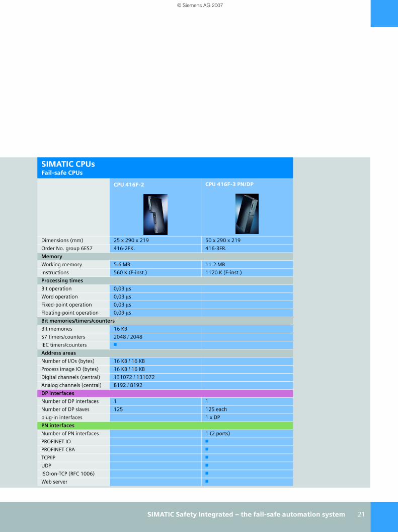
SIMATIC CPUsFail-safe CPUs
CPU 416F-2 CPU 416F-3 PN/DP
Dimensions (mm) 25 x 290 x 219 50 x 290 x 219
Order No. group 6ES7 416-2FK. 416-3FR.
Memory
Working memory 5.6 MB 11.2 MB
Instructions 560 K (F-inst.) 1120 K (F-inst.)
Processing times
Bit operation 0,03 µs
Word operation 0,03 µs
Fixed-point operation 0,03 µs
Floating-point operation 0,09 µs
Bit memories/timers/counters
Bit memories 16 KB
S7 timers/counters 2048 / 2048
IEC timers/counters ■
Address areas
Number of I/Os (bytes) 16 KB / 16 KB
Process image IO (bytes) 16 KB / 16 KB
Digital channels (central) 131072 / 131072
Analog channels (central) 8192 / 8192
DP interfaces
Number of DP interfaces 1 1
Number of DP slaves 125 125 each
plug-in interfaces 1 x DP
PN interfaces
Number of PN interfaces 1 (2 ports)
PROFINET IO ■
PROFINET CBA ■
TCP/IP ■
UDP ■
ISO-on-TCP (RFC 1006) ■
Web server ■
_Safety_4_FactoryAutomation.book Seite 21 Freitag, 13. April 2007 11:55 11
© Siemens AG 2007

22 SIMATIC Safety Integrated – the fail-safe automation system
ET 200 fail-safe I/Os
For connecting actuators and sensors, there is a series of fail-safe distributed ET 200 I/O devices and systems that can be directly connected to PROFIBUS or PROFINET. The fail-safe I/O ET 200M can also be operated centrally in S7-300.
ET 200 offers a series of advantages as shown in the table below.
SIMATIC ET 200Advantage Feature
Maximum safety level Up to SIL 3/Category 4/Performance Level (PL) e, TÜV-certified
Reduced engineering overhead Self-diagnosis and signal test (short-circuit, wire break, discrepancy) without addi-tional programming overhead
Cost reduction through material savings Fail-safe shutdown without additional safety relays
Space-saving structure Co-existence of standard and fail-safe modules in one station
Use of existing network infrastructures Connecting the standard and fail-safe I/Os via only one PROFIBUS or Ethernet cable
Easy switch-over to PROFINET Same I/O modules for PROFIBUS and PROFINET
Fail-safe ET 200 systems
_Safety_4_FactoryAutomation.book Seite 22 Freitag, 13. April 2007 11:55 11
© Siemens AG 2007

SIMATIC Safety Integrated – the fail-safe automation system 23
SIMATIC ET 200Fail-safe I/O
ET 200S ET 200M ET 200pro ET 200eco
Feature The bit-modular I/O mod-ule with up to 8 channels per module
The modular I/O module for high-channel applica-tions with up to 24 channels per module
The modular, multi-func-tional I/O module with high level of protection IP65/67
The cost-effective block I/O with a high degree of protection IP65/67
Number of modules 63 8 16 1 basic module
DI ■ ■ ■ Up to 8 channels
DO ■ ■
Relays ■
DI/DO ■
AI ■
Motor starter ■ ■
Frequency converter ■ ■
For use in hazardous ar-eas
Zones 2, 22 Zones 2, 22
PROFIBUS 4)
Interface module IM 151-1 HF IM 153-2 HFIM 153-2 HF FO
IM 154-2 DP HFWith connection modules for direct con-nection 1), ECOFAST 2) and M12 or 7/8" 3)
Via connection block for ECOFAST or M12, 7/8"
Order No. group: 6ES7 151-1BA. 153-2BA.153-2BB.
154-2AA. 194-3AA.
PROFINET 5)
Interface module IM 151-3 PN HF 6)
IM 151-3 PN FO 7)IM 154-4 PN HF 6)
With connection mod-ules for M12 or 7/8"
Order No. group: 6ES7 151-3BA.151-3BB.
154-4AB.
NEW
1) Direct connection with cable gland2) ECOFAST: Standardized connecting cable with hybrid cables3) M12, M 7/8": Connection method with widespread connector standard4) Transfer rate PROFIBUS 12 Mbit/s
5) Transfer rate PROFINET 100 Mbit/s6) With integrated 2-port switch, e.g. for simple setup of linear structures7) For setting up optical networks with easy to configure plastic fiber-optic
cables
_Safety_4_FactoryAutomation.book Seite 23 Freitag, 13. April 2007 11:55 11
© Siemens AG 2007
24 SIMATIC Safety Integrated – the fail-safe automation system
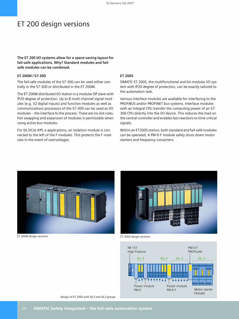
ET 200 design versions
The ET 200 I/O systems allow for a space-saving layout for fail-safe applications. Why? Standard modules and fail-safe modules can be combined.
ET 200M / S7-300
The fail-safe modules of the S7-300 can be used either cen-trally in the S7-300 or distributed in the ET 200M.
The ET 200M distributed I/O station is a modular DP slave with IP20 degree of protection. Up to 8 multi-channel signal mod-ules (e.g. 32 digital inputs) and function modules as well as communications processors of the S7-300 can be used as I/O modules – the interface to the process. There are no slot rules. Hot swapping and expansion of modules is permissible when using active bus modules.
For SIL3/Cat.4/PL e applications, an isolation module is con-nected to the left of the F modules. This protects the F mod-ules in the event of overvoltages.
ET 200S
SIMATIC ET 200S, the multifunctional and bit-modular I/O sys-tem with IP20 degree of protection, can be exactly tailored to the automation task.
Various interface modules are available for interfacing to the PROFIBUS and/or PROFINET bus systems. Interface modules with an integral CPU transfer the computing power of an S7-300 CPU directly into the I/O device. This reduces the load on the central controller and enables fast reactions to time-critical signals.
Within an ET200S station, both standard and fail-safe modules can be operated. A PM-D F module safely shuts down motor starters and frequency converters.
Design of ET 200S with SIL2 and SIL3 groups
ET 200S design versionsET 200M design versions
Power modulePM-E
Power modulePM-E F
PM-D FPROFIsafe
IM 151High Feature
SIL 3
Motor starterFailsafe
SIL 2SIL 2 SIL 3
_Safety_4_FactoryAutomation.book Seite 24 Freitag, 13. April 2007 11:55 11
© Siemens AG 2007

SIMATIC Safety Integrated – the fail-safe automation system 25
ET 200pro
SIMATIC ET 200pro is a very compact, extremely rugged and high-performance I/O unit with IP65/67 degree of protection. It does not require a control cabinet and can be directly mounted on the machine. Its modular and time-saving design allows flexible and customer-specific distributed automation solutions to be implemented.
ET 200pro can be connected to the tried and tested fieldbus PROFIBUS or to PROFINET, the open Industrial Ethernet stan-dard for company-wide automation.
Within an ET 200pro station, both standard and fail-safe mod-ules can be operated. This can also be arranged in a potential group for requirement SIL 3/cat.4/PL e.
ET 200eco
SIMATIC ET 200eco is the digital block I/O with IP65/67 degree of protection. It consists of a basic module and two different connection blocks. Selection is possible between M12, 7/8" and ECOFAST.
A matched module range for digital I/Os as well as a fail-safe module with 8 fail-safe inputs is available.
The pin assignment for the actuators and sensors is modeled on the IP65/67 standardization trends.
ET 200pro design versions ET 200eco design version
_Safety_4_FactoryAutomation.book Seite 25 Freitag, 13. April 2007 11:55 11
© Siemens AG 2007

26 SIMATIC Safety Integrated – the fail-safe automation system
Technical data ET 200
SIMATIC ET 200SFail-safe modules
Digital input module 4/8 F-DI
Digital input 4 F-DI/3 F-DO
Digital out-put 4 F-DO
Relay module 1F-RO
Power mod-ule PM-D F 24 V DC
Power mod-ule PM-E F pp 24 V DC
Power mod-ule PM-E F pm 24 V DC
Number of I/Os 4 (2-channel for SIL 3 sen-sors)8 (1-channel for SIL 2 sen-sors)
4 inputs (SIL 2)3 outputs 2A (SIL 2)
4 at 24 V/2 A (current-sink-ing)
1 relay output24 V DC, 24 - 230 V AC, 5 A
6 disconnec-tion groups, each 3 A (ag-gregate cur-rent 5 A)
1 relay output 24 V DC (ag-gregate cur-rent 10 A)(source/source output)
Up to 2 SIL 3 outputs for 24 V/2 A, 1 relay output 24 V DC(aggregate cu-urent 10 A) (source/sink output)
Input or output voltage
24 V DC
Order No. group
6ES7 138-4FA. 6ES7 138-4FC. 6ES7 138-4FB. 6ES7 138-4FR. 3RK1 903-3BA. 6ES7 138-4CF4.
6ES7 138-4CF.
NEW
Fail-safe motor starter
In addition to a circuit breaker/contactor combination, the fail-safe motor starters have a safe electronic evaluation circuit for fault de-tection.If the contactor to be switched in the case of an EMERGENCY STOP fails, the analyzing electronics detect a fault and deactivate the cir-cuit breaker in the motor starter in a fail-safe manner.
Performance at 500 V 7.5 KW
Rated operational current IE 16 A
Short-circuit breaking capacity 50 kA at 400 V
Coding Allocate one of 6 disconnect groups
Order No. group Motor starter
3RK1 301-0.B13-.AA2
Order No. group Terminal module
3RK1 903-3A.
PM-D F power module
Number of int. disconnection groups
6
Aggregate current of outputs 5 A
Diagnostics Can be read out
Order No. group 3RK1 903-3BA.
F-CM fail-safe contact multiplier
Contacts 4 NO
Diagnostics Power failure, equipment failure
Switching capacity 1.5 A/24 V
Order No. group 3RK1 903-3CA.
Fail-safe power module PM-D F X1 Supply terminal module
Operation Standalone with external safety technology
Double terminals for disconnec-tion groups
6
Diagnostics Voltage failure
Order No. group 3RK1 903-3DA.
Fail-safe frequency converter
The fail-safe frequency converters allow safety functions for en-coderless speed-controlled asynchronous motors:
■ Safe torque off
■ Safe stop 1
■ Safely limited speed
Power Up to 4 kW
Order No. group 6SL3 244-0S.
_Safety_4_FactoryAutomation.book Seite 26 Freitag, 13. April 2007 11:55 11
© Siemens AG 2007

SIMATIC Safety Integrated – the fail-safe automation system 27
SIMATIC ET 200MFail-safe modules
Digital input SM 326 F DI 24
Digital input SM 326 F DI 8 NAMUR
Digital output SM 326 FDO 10 PP
Digital output SM 326 FDO 8 PM
Analog input SM 336 F AI 6
Number of I/Os up to 12 (2-channel for SIL 3 sensors)24 (1-channel for SIL 2 sensors)
4 (2-channel)8 (1-channel)
10 (source/source output)
8 (source/sink out-put)
6 (2-channel for SIL 3 sensors)13 bits
Input or output volt-age
24 V DC NAMUR 24 V DC
Interrupts Diagnostic interrupt
Input or output cur-rent
2 A per channel at signal "1" 4…20 mA
Order No. group 6ES7 326-1BK. 6ES7 326-1RF. 6ES7 326-2BF. 6ES7 326-2BF. 6ES7 336-1HE.
SIMATIC ET 200ecoFail-safe modules
4/8 F-DI
Number of inputs 4 (2-channel for SIL 3 sensors), 8 (1-channel for SIL 2 sensors)
Input voltage 24 V DC
Order No. group 6ES7 148-3FA.
SIMATIC ET 200proFail-safe modules
EM 8/16 F-DI EM 4/8 F-DI/F-DO
Number of inputs 8 (2-channel for SIL 3 sensors)16 (1-channel for SIL 2 sensors)
4 (2-channel for SIL 3 sensors)8 (1-channel for SIL 2 sensors)
Input voltage 24 V DC
Number of outputs 4 (source/sink out-put), SIL 3
Output current 24 V DC / 2 A
Order No. group 6ES7 148-4FA. 6ES7 148-4FC.
Fail-safe frequency converter
The fail-safe frequency converters allow safety functions for en-coderless standard asynchronous motors:
■ Safe torque off
■ Safe stop 1
■ Safely limited speed
Power 1.1 kW (0°…55° C); 1.5 kW (0°…45°C)
Order No. group 6SL3 235-OTE.
_Safety_4_FactoryAutomation.book Seite 27 Freitag, 13. April 2007 11:55 11
© Siemens AG 2007

28 SIMATIC Safety Integrated – the fail-safe automation system
Engineering
The fail-safe systems are programmed with STEP 7 and S7 Distributed Safety.
STEP 7
STEP 7 offers functions for all phases of an automation project – from configuring to commissioning, testing and service. Thus, STEP 7 supports the entire engineering workflow.
STEP 7 encompasses both the hardware configuration of the system and the parameterization of the modules. Therefore, no more hardware settings must be carried out. Configuration of the F modules is done using HW-Config, the STEP 7 config-uration tool, just as it is done for the standard I/Os.
With STEP 7, the communication connections within a project are established via a graphical user interface. STEP 7 contains the central tool for project management: the SIMATIC Man-ager.
Parameterization of an F module in STEP 7
The SIMATIC Manager views not just one CPU but the overall system – regardless of how many controllers, drives and HMI devices the solution has. The interconnections can be drawn across the entire project with STEP 7.
The structured programming makes it significantly easier to design a user program. To this end, it is divided into manage-able, easily testable units, the so-called blocks. A comprehen-sive library of standard blocks makes program creation extremely efficient.
S7 Distributed Safety
S7 Distributed Safety offers commands, operations and blocks for implementing safety-related programs in LAD and FBD. To this end, there is a library with pre-prepared, TÜV-accepted blocks for safety-related functions. Users do not need addi-tional engineering expertise, because the programming is done in the traditional STEP 7 environment. S7 Distributed Safety also encompasses error detection functions and safety inspections during generation of the safety program.
The safety program from the standard user program is called up via the so-called F-call (e.g. from an alarm OB such as OB 35). Apart from the safety program, a standard program can also be run on the same CPU.
S7 Distributed Safety supports the comparison of safety pro-grams and simplifies the system acceptance with the gener-ated program printout.
S7 Distributed Safety: The entire programming process is carried out in a func-tion block diagram (FBD, see above) or ladder diagram (LAD)
_Safety_4_FactoryAutomation.book Seite 28 Freitag, 13. April 2007 11:55 11
© Siemens AG 2007

SIMATIC Safety Integrated – the fail-safe automation system 29
Industry-specific F software packages
The optional burner package contains an F-library with blocks for industrial gas and oil burners. The blocks are certified by TÜV for heating vessels and boilers (see Table).
The other optional press package contains finished function blocks in order to implement press safety functions in accor-dance with EN 954-1, Cat.4 and EN 61508 – for example, for mechanical, hydraulic or pneumatic presses.
Function examples
On the Internet you will find practical function examples that cover the typical requirements of industrial safety technology. They describe how certain safety functions can be imple-mented using S7 Distributed Safety and which components are required for the same. The examples contain function descriptions, component lists and circuit plans as well as one STEP 7 project that can be loaded. They will thus help you in speedy and simple implementation of the described tasks.
Some examples include:
■ Protective door with spring-actuated tumbler
■ Emergency stop with acknowledgment
■ Light curtain with muting function
■ Safe standstill recording and safely reduced speed with F-CPU and MASTERDRIVES
You will find these and other examples on the Internet under www.siemens.de/safety-functional-examples
Softwarefor fail-safe applicationsPackage S7 Distributed Safety Burner option package Press option package
Library Certified modules, e.g. emergency stop, two-hand control, muting, door monitoring
Certified burner modules Certified modules
Certificates IEC 61508: 2000 SIL 1 - 3EN 594-1 : 1997 Cat. 2 - 4IEC 61511: 2003EN 60204-1 : 1997IEC 62061: 2005NFPA 79-2002, NFPA 85
IEC 61508: 2000, Part 3, SIL3DIN EN 676: 2003DIN EN 267: 1999DIN EN 12952-8: 2002DIN EN 12953-7: 2002TRN 411: 1997, TRN 412: 1997DIN EN 746-2: 1997DIN VDE0116: 1989
EN 954-1, Cat. 4EN 61508
Requirement STEP 7 S7 Distributed Safety S7 Distributed Safety
Engineering pack-age
1 license per engineering location
Runtime package 1 license per CPU
Order No. group 6ES7 833-1FC. 9AL3 100-1AD5. 6AU1 837-0EA.
_Safety_4_FactoryAutomation.book Seite 29 Freitag, 13. April 2007 11:55 11
© Siemens AG 2007

30 References
References
ZF Lenksysteme GmbH – Manufacturer of motor vehicle steering systems, Germany
Requirements ZF Lenksysteme GmbH (ZFLS), which is headquartered in Schwäbisch Gmünd, is a leading manufacturer of vehicle steering systems in the field of safety technology. In order to be state-of-the-art, the company decided to replace the con-ventional, hard-wired safety technology with modern, freely programmable PLC systems from Siemens. ZFLS believed that this change would bring about an increased level of flexibility and considerable cost savings for engineering and mainte-nance. One of the first applications to be implemented on this basis: a hydraulic press for preforming gear racks in an auto-mated manufacturing unit.
Solution ZFLS, the technological leader in steering technology, has decided on the fail-safe SIMATIC S7-300F controller with the 317F-2 DP CPU in the medium performance range and for the fail-safe ET 200S I/O modules optimized for use with it. Both the controller and the I/Os are approved by the TÜV. They guar-antee functional safety up to SIL 3 as per IEC 61508. Safety-related and standard program parts run side-by-side on the fail-safe CPU. This significantly simplifies the implementation of complex applications. No stand-alone safety controller is required. This architecture also permits in the I/O a hybrid, fine-grained setup, which is tailored exactly to the require-ments. Controllers and I/O communicate via PROFIBUS. The fieldbus allows safe and standard data traffic on one and the same line via the PROFIsafe profile. This makes a separate safety bus superfluous, which reduces the installation outlay even in comparison to other PLC-based safety concepts.
AdvantagesThe management at ZF Lenksysteme are sure they have found a suitable basis for more flexible fail-safe automation solutions with the fail-safe SIMATIC controllers. Even during the first use, it was possible to reduce the total costs by around 10%, due in no small part to the use of fail-safe PLC and bus technol-ogy. For the future, the company is planning to integrate sev-eral system sections in this way via PROFIBUS or PROFINET into a fail-safe control unit in order to be able to profit from even greater savings.
_Safety_4_FactoryAutomation.book Seite 30 Freitag, 13. April 2007 11:55 11
© Siemens AG 2007

References 31
CAMotion Inc. – Mechanical Engineering, Atlanta, USA
RequirementsThe American system integrator CAMotion, based in Atlanta, Georgia, implemented an innovative safety control network for one of its customers for use with large-scale overhead crane robotic systems - an innovative solution which allows standard and fail-safe communication to be conducted wire-lessly. Additional requirements: cost savings compared to con-ventional approaches, a high degree of ruggedness and reli-ability and minimized risk. In addition, CAMotion's solution should stand out due to its future-oriented design: It should be possible to flexibly expand it and adapt it to current require-ments.
Solution CAMotion decided on what they themselves described as the only solution that met the high requirements: a combination of fail-safe Siemens controllers, that are connected via PROFI-BUS with PROFIsafe profile to the safety components that are in use.
The following are used: SIMATIC CPU 315F-2 PN/DP (on the floor) and the fail-safe I/O SIMATIC ET200S with safety mod-ules (on the moving crane). The basis for the wireless commu-nication is created by the industrial Wireless LAN Access Points SCALANCE W788 and industrial Ethernet switches SCALANCE X208.
AdvantagesCAMotion's solution is a real milestone in automation: For the first time, safety and wireless technology were combined in one application - worldwide. The solution wins over the cus-tomer in every respect. Clear cost savings result from the fact that only one network is needed for all of the tasks.
And the customer sees his high requirements met without exception: The flexible, expandable and modular solution has been working extremely reliably since it was commissioned and it can be easily maintained. This is due to both the conve-nient diagnostics capabilities and the efficient fault clearing capabilities.
_Safety_4_FactoryAutomation.book Seite 31 Freitag, 13. April 2007 11:55 11
© Siemens AG 2007

32 References
Volkswagen –Manufacture of radiators at the Hannover plant in Germany
RequirementsIn the future, the automation initiative of German automobile manufacturers (AIDA) will increasingly use PROFINET with integrated personnel safety as a standard process of the indus-trial Ethernet. The goal of AIDA, whose members include Audi, BMW, Daimler-Chrysler and VW, is the simple and uniform con-nection of the automation components that are used.
In their plant in Hannover, Volkswagen AG operates a fully automatic production plant for water coolers. It proves that distributed system configurations with integrated safety on the basis of PROFINET I/O can be implemented – with a maxi-mum degree of product quality and process safety.
SolutionCommunication with the distributed I/O takes place via PROFI-NET with integrated safety technology. The individual fail-safe modules of the ET 200S communicate via PROFINET I/O with the central system controller CPU 416F-2DP with CP-443-1 Advanced of the SIMATIC S7-400F family via PROFIsafe. Also connected to it via PROFINET: the SIMATIC Panel PC670 for operator control and monitoring.
AdvantagesThe solution with PROFINET proves its worth through consid-erable increase in transfer performance. As PROFINET sup-ports IRT (Isochronous Real Time) technology, the latter offers automation solutions as well as real-time capability along with isochronous mode - a very important aspect of highly dynamic processes. Furthermore, data archiving is also much more effective.
_Safety_4_FactoryAutomation.book Seite 32 Freitag, 13. April 2007 11:55 11
© Siemens AG 2007

References 33
ContiTech –Manufacturer of quality hoses in Germany
RequirementsContiTech specializes in rubber and plastic technology and is a leading manufacturer of quality hoses. As a partner in devel-opment and an initial supplier, the company enjoys an out-standing reputation in the automobile industry and in many other sectors around the world. To be able to always deliver "just in time" and meet the customer's demands 100% in the future, ContiTech wants to reduce the risk of unscheduled sys-tem downtimes to an absolute minimum. For this reason, it has modernized its hose manufacturing machines. The new solution should also provide a higher degree of flexibility in production.
Solution In the course of modernizing the system, ContiTech simulta-neously carried out two essential, innovative steps: the switch-over from the previous contactor control to systematic decen-tralization and the use of a single bus system for standard and fail-safe signals. The ET 200S distributed I/O in connection with PROFIsafe allowed the simple and efficient combination of standard control technology and safety technology.
Also in use: the fail-safe SIMATIC 315F-2DP controller, which can process standard and fail-safe signals. The ET200 configu-rator allowed both safety-related and standard components to be quickly and easily selected. This meant that the quasi "built-in" plausibility test made mistakes in the selection of the com-ponents nearly impossible.
AdvantagesContiTech is excited about the new solution: It provides the flexibility needed in production. And the design of the safety circuits was extremely easy. This innovative concept also opens up new diagnostic possibilities, because the individual system sections can be taken into consideration completely separately at any time.
Also an advantage: the central data storage with one CPU for a project – also against the backdrop of future system optimi-zations or modifications. And since there were no interface-related problems, the commissioning of the new system only took one week.
_Safety_4_FactoryAutomation.book Seite 33 Freitag, 13. April 2007 11:55 11
© Siemens AG 2007

34 Overall Safety Integrated portfolio
Overall Safety Integrated portfolio
Fail-safe sensors Fail-safe switching technology
Sensing Sensing
Contact-free Touch-sensitive
SIMATIC Sensors1) Light curtains2) Light grids3) Light barriers
SIMATIC SensorsLaser scanners
SIRIUSPosition switchesHinged switchesShort-stroke switchesSolenoid-operated switches (contact free)
Description
Contact-free safety systems Contact-free safety systems For mechanical controlling at safety devices, safety door locks
Application
■ Monitoring of hazardous points and hazardous areas
■ Cordoning off hazardous areas at stationary and mobile units
■ Securing of safety doors and flaps against unauthorized access
■ Reliable sensing of hazardous movements
Up to Cat. 4 according to EN 954-1 Up to SIL 3 according to IEC 61508Up to SIL 4 according to IEC 61496
Up to Cat. 3 according to EN 954-1Up to SIL 2 according to IEC 61508Up to type 3 according to IEC 61496
Up to Cat. 4 according to EN 954-1Up to SIL 3 according to IEC 61508
NFPA 79, NRTL-listed NFPA 79, NRTL-listed –
Safety functions
1)…3) Fail-safe shutdown1) Cycle monitoring1), 2) Muting contactor control3) Muting contactor control
with processing unit1) Fixed and floating blanking
■ Fail-safe shutdown■ Configurable protective zones■ Max. 4 selectable protective zones■ Horizontal and vertical cordoning: Passage
control, cordoning off hazardous areas, leg detection, arm and hand protection
■ Locking the safety door ■ Reliable sensing of hazardous
movements
Other features
Degree of protection IP65 Degree of protection IP65 Degree of protection IP65/67
1) Resolution of 14…90 mm2) 2, 3, 4 beams 3) 1 beam 1) + 2) Configuration using opto-magnetic
key (teach-in) and SafetyLab diagnos-tics and parameterization software
1) + 2) Additional safety switches can be con-nected
1) + 2) Diagnostics software
■ Resolution 150 mm, 70 mm, 50 mm, 40 mm, 30 mm
■ 4 m protective zone,15 m warning zone■ Field selection during operation■ Simple programming of safety and warn-
ing fields■ Software: LS4soft
■ Housing according to DIN EN 50047 in metal and plastic
■ Positively-driven contacts■ Various operating mechanisms■ Galvanically isolated contacts with movable
double-break contacts■ Opening already after 4° turning movement ■ Tamper-proof
Communication
ASIsafe, PROFIBUS (PROFIsafe profile) ASIsafe, PROFIBUS (PROFIsafe profile) Partially with direct connection to ASIsafe
Overall Safety Integrated portfolio
_Safety_4_FactoryAutomation.book Seite 34 Freitag, 13. April 2007 11:55 11
© Siemens AG 2007

Overall Safety Integrated portfolio 35
Overall Safety Integrated portfolio
Fail-safe communication via ASIsafe
Sensing
via ASIsafe
SIRIUS1) EMERGENCY STOP/emergency stop2) Cable-operated switches3) Two-hand operation consoles4) Foot switches5) Signaling columns/Integrated lights
ASIsafe modulesSlimLine S22, 5FCompact modules K45F, K20F
DP/AS-i F-Link(ASIsafe solution PROFIsafe)
1) Emergency stop for fail-safe interruption of the safety circuit
2) Safe switch-off using a pull wire (or via integrated EMERGENCY STOP/emergency stop pushbutton)
3) Manual, safe initiation of dangerous movements
4) Locking foot operations5) Acoustic and visual alarm and signalling
devices
For recording safe signalsIn cabinet and in the field
For optimum conversion of ASIsafe to PROFIsafe
■ Emergency stop applications in production and process industry
■ Status signaling to machines and plants
■ All safety applications infactory automation (Exception: Safe Drives)
■ All safety applications infactory automation (Exception: Safe Drives)
Up to Cat. 4 according to EN 954-1Up to SIL 3 according to IEC 61508
Up to Cat. 4 according to EN 954-1 andSIL3 to IEC 61508
Up to Cat. 4 according to EN 954-1 andSIL3 to IEC 61508
– NFPA 79, NRTL-listed NFPA 79, NRTL-listed
■ Emergency stop
■ Approval
■ Safe recording of mechanical and contact-less protective devices
■ Safe gateway for transfer of the ASIsafe sig-nals into PROFIsafe message frame
Degree of protection IP65/67 IP20 or IP67 degree of protection Degree of protection IP20
1) Contact units of different NC assemblies2) Area of application up to max. 50 m length3) Additional command devices can be in-
stalled4) Also for rough environments5) Modular combinations are possible – in-
candescent lamps or LEDs
Design in IP20: Slimline 22.5F with 22.5mmDesigns in IP67:a) K20F 2F-DI: 20 mm wide; AS-i interface via
M12 round cableb) K45F 2F-DI: 45 mm widec) K45F 4F-DI: 45 mm wide (double slave)d) K45F 2F-DI/2DO: 45 mm wide, optional
supply of standard outputs from aUx 24V
■ Programming of safety logic via Distributed Safety (SIMATIC) or SPL (SINUMERIK)
Partially with direct connection to ASIsafe ASIsafe ASIsafe and PROFIsafe
_Safety_4_FactoryAutomation.book Seite 35 Freitag, 13. April 2007 11:55 11
© Siemens AG 2007

36 Overall Safety Integrated portfolio
Overall Safety Integrated portfolio
Fail-safe switching technology Fail-safe motion control systems
Evaluating
Conventional Configurable
SIRIUS1) Safety relays 3TK28 (relay)2) Safety relays 3TK28 (electronic)3) ASIsafe safety monitor (ASIsafe Solution local)
SIRIUSSafety Unit TM121C
Description
1), 2) Monitoring the assigned protective equipment3) due to parameterization, can be used for many local safety
functions
Compact device for monitoring movements, e.g. at presses
Application
■ All safety applications in factory automation ■ Metalforming, e.g. for cordoning off the hand-insertion point
1) + 2) Up to Cat. 4 according to EN 954-12) + 3) Up to Cat. 4 according to EN 954-1, up to SIL 3 according to
IEC 61508
Up to Cat. 4 according to EN 954-1Up to SIL 3 according to IEC 61508
NFPA 79, NRTL-listed NFPA 79, NRTL-listed (Canada)
Safety functions
1)+2) Reliable evaluation of mechanical and contactless protective devices and press control units
3) Reliable evaluation of mechanical and contactless protective devices including reaction (e.g. shutdown) on 1-2 enabling circuits
■ Two-hand operation and foot operations■ Emergency stop, light curtain■ Safety door and safety grid monitoring■ Safe mode selector switch■ Triggering of safety valves■ Motion sensor control (frequency input)
Other features
Degree of protection IP20 Degree of protection IP20
1) + 2) Simple, cost-effective solution for safety applications3) Parameterization of the safety logic via graphical software
tool "asimon"
■ Safe evaluation of cam signals■ 32 fail-safe inputs■ 8 fail-safe outputs■ 2 fail-safe frequency inputs■ Fully programmed function blocks for press applications are
parameterized and can be used several times
Communication
3) ASIsafe RS232
_Safety_4_FactoryAutomation.book Seite 36 Freitag, 13. April 2007 11:55 11
© Siemens AG 2007

Overall Safety Integrated portfolio 37
Overall Safety Integrated portfolio
Fail-safe controllers Fail-safe switching technology
Evaluating Reacting
Programmable Electro-mechanically / electronically
SIMATICControllers for the manufacturing indus-try
SIMATICFail-safe I/O for the manufacturing indus-try
SIRIUS1) Safety Motor starter ET 200S Solution local2) Safety Motor starter ET 200S Solution PROFIsafe3) Safety Motor starter ET 200pro Solution local
Scalable fail-safe systems■ ET 200S F-CPU
■ S7-300F
■ S7-400F
Scalable and redundant I/O systems ■ ET 200eco■ ET 200M■ ET 200S■ ET 200proIncluding■ Relay module■ Digit input modules■ Digital output modules■ Analog input modules■ Motor starter■ Frequency converter
Safe switch-off with integrated motor protection 1) + 2) Motor starter for starting and safe switch-off
using conventional switching technology2) Motor starter for starting and safe selective
switching-off1) + 3) On-site safety application with motor starter
All safety applications for the production industry
All safety applications for the manufac-turing/process industry
All safety applications in production automation and distributed drive tasks such as in conveyor systems or lift drives
Up to Cat. 4 according to EN 954-1 Up to SIL 3 according to IEC 61508
Up to Cat. 4 according to EN 954-1 Up to SIL 3 according to IEC 61508
Up to Cat. 4 according to EN 954-1Up to SIL 3 according to IEC 61508
NFPA 79, NRTL-listed NFPA 79, NRTL-listed NFPA 79, NFPA 85, NRTL-listed
■ Integrated diagnostic functions and self test routines
■ When a fault occurs, the application can be transferred to a safe status in a flexible manner and retained there
■ Integrated signal testing and discrepancy time monitoring
■ Safe shutdown
Degree of protection IP20 Degree of protection up to IP67 Degree of protection 1) + 2) IP20, 3) IP65
■ Co-existence of standard and fail-safe programs in one CPU
■ Pre-fabricated, TÜV-certified safety components
■ Software: STEP 7 FBD, LAD, S7 Distrib-uted Safety
■ F libraries for press and burner applica-tions
■ A distributed I/O system with standard and fail-safe input and output modules
■ Configuration of signal testing and discrepancy time visualization using STEP 7
■ Group switch-off possible■ 1) + 2) Output range of motor starter up to 7.5 kW■ 2) Selective switching
Fail-safe communication via PROFINET/PROFIBUS using PROFIsafe profile
■ Fail-safe communication PROFIBUS with PROFIsafe profile: all systems
■ PROFINET with PROFIsafe profile:ET 200S, ET 200pro
2) Fail-safe communication via PROFIBUS/PROFINET with PROFIsafe profile1) + 3) Communication via PROFIBUS/PROFINET
_Safety_4_FactoryAutomation.book Seite 37 Freitag, 13. April 2007 11:55 11
© Siemens AG 2007

38 Overall Safety Integrated portfolio
Overall Safety Integrated portfolio
Fail-safe drives
Sensing, evaluating, reacting
Electronically
SIMATIC ET 200S FC SIMATIC ET 200pro FC 1) SINAMICS G1202) SINAMICS G120D
Description
System-integrated, central drive (frequency converter) with integrated, independent safety functions at encoderless standard asynchronous motors
System-integrated drive (frequency con-verter) with integrated, independent safety functions at encoderless standard asynchro-nous motors
1) Modular, central frequency converter2) Distributed frequency converter with inte-
grated, independent safety functions at encoderless standard asynchronous motors
Application
Decentralized drive tasks, such as conveyor systems, lift drives
Distributed drive tasks especially for convey-or systems
1) Conveyor systems, pumps, fans, compressors2) Distributed drive tasks especially for conveyor
systems
Cat. 3 according to EN 954-1SIL 2 according to IEC 61508
Cat. 3 according to EN 954-1SIL 2 according to IEC 61508
Cat. 3 according to EN 954-1SIL 2 according to IEC 61508
NFPA 79, NFPA 85, NRTL-listed (via ET 200S) NFPA 79, NFPA 85, NRTL-listed
Safety functions
■ Safe torque off
■ Safe stop 1
■ Safely limited speed
■ Safe torque off
■ Safe stop 1
■ Safely limited speed
■ Safe torque off
■ Safe stop 1
■ Safely limited speed
■ Safe brake control (G120 only)
Other features
Degree of protection IP20 Degree of protection IP65 Degree of protection IP20
■ Modular structure in decentralized I/O ET 200S (0.75, 2.2 and 4 kW)
■ Standard and fail-safe frequency converter can be operated in one station
■ Fail-safe and standard inputs via ET 200S station■ Regenerative operation by means of regenera-
tive feedback without chopper or brake resis-tance
■ V/f control■ Vector control with and without sensor■ Torque control
■ Power: 1.1 (1.5 kW)■ Control of safety functions via Safety Local
Repair Module (F-RSM) inputs ■ Cabinetless, distributed structure ■ Flexibility due to open combination of ET
200pro modules with the frequency converter■ Capable of regeneration (therefore no need for
braking resistor and chopper)■ V/f control■ Vector control with and without sensor
1) Modular design for power levels from 0.37 to 90 kW
2) Distributed design with high level of protection for power levels from 0.75 to 7.5 kW
1+2):■ Capable of regeneration■ Regenerative operation by means of regenerative
feedback without chopper or brake resistance■ V/f control■ Vector control with and without sensor
Communication
Fail-safe communication via PROFIBUS using PROFIsafe profile
Fail-safe communication via PROFINET/PROFIBUS using PROFIsafe profile
Fail-safe communication via1) PROFINET/PROFIBUS with PROFIsafe profile2) PROFIBUS with PROFIsafe profile
_Safety_4_FactoryAutomation.book Seite 38 Freitag, 13. April 2007 11:55 11
© Siemens AG 2007

Overall Safety Integrated portfolio 39
Overall Safety Integrated portfolio
Fail-safe drives Fail-safe motion control systems
Sensing, evaluating, reacting
Electronically
SINAMICS S120 1) SINUMERIK 840D powerline with SIMODRIVE 611digital2) SINUMERIK 840D sl with SINAMICS S120
Drive system for high-performance individual and multiple applica-tions in mechanical and plant engineering with integral, independent safety functions
Numerical control with integral safety technology in controller and drive
Motion Control tasks in individual and multiple applications in me-chanical and plant engineering (printing, paper, packaging, plastic machinery, presses, punches, handling equipment, etc.)
Machine tools, e.g. for cordoning off during setup operations when the safety door is open
Cat. 3 according to EN 954-1 SIL 2 according to IEC 61508
Cat. 3 3) according to EN 954-1SIL 2 3) according to IEC 61508
NFPA 79 1), NRTL-listed 1) NFPA 79 3), NRTL-listed 3)
■
■ Safe torque off
■ Safe stop 1 and 2 2)
■ Safe brake control 2)
■ Safe operational stop
■ Safely limited speed
■ Safe speed monitoring
■ Safe torque off and safe operational stop
■ Safely reduced speed
■ Safe software limit switches and cams
■ Safe programmable logic
■ Safe brake management
■ Integrated acceptance testing
Degree of protection IP20 Degree of protection IP20
■ For outputs of 0.12 to 1200 kW
■ With integral positioning functions
■ Servo control
■ Vector control
■ V/f control
■ Modular design
■ Auto-configuring with electronic rating plates
■ 64 safe inputs / outputs
■ High-speed processing with Look Ahead
■ Following-error-free processing
■ Jerk-limited acceleration
■ NURBS interpolation
■ 5-axis functions
Fail-safe communication via PROFIBUS using PROFIsafe, PROFINET, CANOpen
Fail-safe communication via PROFIBUS using PROFIsafe profile
1) A
vaila
ble
soon
2) F
or o
utp
uts
of
up
to 1
00
KW
(bl
ock
size
an
d bo
ok
size
dev
ices
)
3) A
vaila
ble
soon
for
SIN
UM
ERIK
84
0D
sI
_Safety_4_FactoryAutomation.book Seite 39 Freitag, 13. April 2007 11:55 11
© Siemens AG 2007

Siemens AG
Automation and DrivesIndustrial Automation SystemsPostfach 484890327 NÜRNBERGGERMANY
www.siemens.com/safety- integrated
The information provided in this brochure contains descriptions or charac-teristics of performance which in case of actual use do not always apply as described or which may change as a result of further development of the products. An obligation to provide the respective characteristics shall only exist if expressly agreed in the terms of contract. Subject to change without prior notice.
All product designations may be trademarks or product names of Siemens AG or supplier companies whose use by third parties for their own purposes could violate the rights of the owners.
Subj
ect
to c
han
ge w
ith
out
prio
r n
otic
e | O
rder
No.
6ZB
53
10
-0N
B02
-0BA
1 |
Dis
po 2
61
00
| B
S 0
40
7 4
. RO
T 4
0 D
E/70
14
73
| Pr
inte
d in
Ger
man
y | ©
Sie
men
s A
G 2
00
7
Further information can be found on the Internet
SIMATIC Safety Integrated for the manufacturing industry:www.siemens.com/safety-integrated
Distributed I/O:www.siemens.com/et200
Totally Integrated Automation:www.siemens.com/totally-integrated-automation
Training Courses on Safety Integrated:www.siemens.com/sitrain-safetyintegrated
Service & Support:www.siemens.com/automation/service&support
SIMATIC partners:www.siemens.com/automation/partners
Order or download additional informative material:www.siemens.com/simatic/printmaterial
SIMATIC Guide Manuals:www.siemens.com/simatic-docu
A&D Mall online ordering system:www.siemens.com/automation/mall
_Safety_4_FactoryAutomation.book Seite 40 Freitag, 13. April 2007 11:55 11
© Siemens AG 2007