stainless steel air motors - kuroda pneumatics ltd. pdf/p1v-s.pdf · 6 stainless steel air motors...
TRANSCRIPT
Stainless Steel Air Motors
aerospaceclimate control electromechanicalfiltrationfluid & gas handlinghydraulicspneumaticsprocess controlsealing & shielding
Series P1V-S
�
Stainless Steel Air Motors P1V-S
07.10
www.parker.com/euro_pneumatic
Important!Before carrying out service activities, make sure the air motor is vented. Before disassembling the motor, disconnect the primary air hose to ensure that the air supply is interrupted.
NOTE! All technical data in the catalogue are typical values. The air quality is a major factor in the service life of the motor, see ISO 8573-1.
SALE CONDITIONSThe items described in this document are available for sale by Parker Hannifin Corporation, its subsidiaries or its authorized distributors. Any sale contract entered into by Parker will be governed by the provisions stated in Parker’s standard terms and conditions of sale (copy available upon request).
WARNING
FAILURE OR IMPROPER SELECTION OR IMPROPER USE OF THE PRODUCTS AND/OR SYSTEMS DESCRIBED HEREIN OR RELATED ITEMS CAN CAUSE DEATH, PERSONAL INJURY ANDPROPERTY DAMAGE.This document and other information from Parker Hannifin Corporation, its subsidiaries and authorized distributors provide product and/or system options for further investigation by users having technical expertise. It is important that you analyze all aspects of your application and review the information concerning the product or system in the current product catalog. Due to the variety of operating conditions and applications for these products or systems, the user, through its own analysis and testing, is solely responsible for making the final selection of the products and systems and assuring that all performance, safety and warning requirements of the application are met. The products described herein, including without limitation, product features, specifications, designs, availability and pricing, are subject to change by Parker Hannifin Corporation and its subsidiaries at any time without notice.
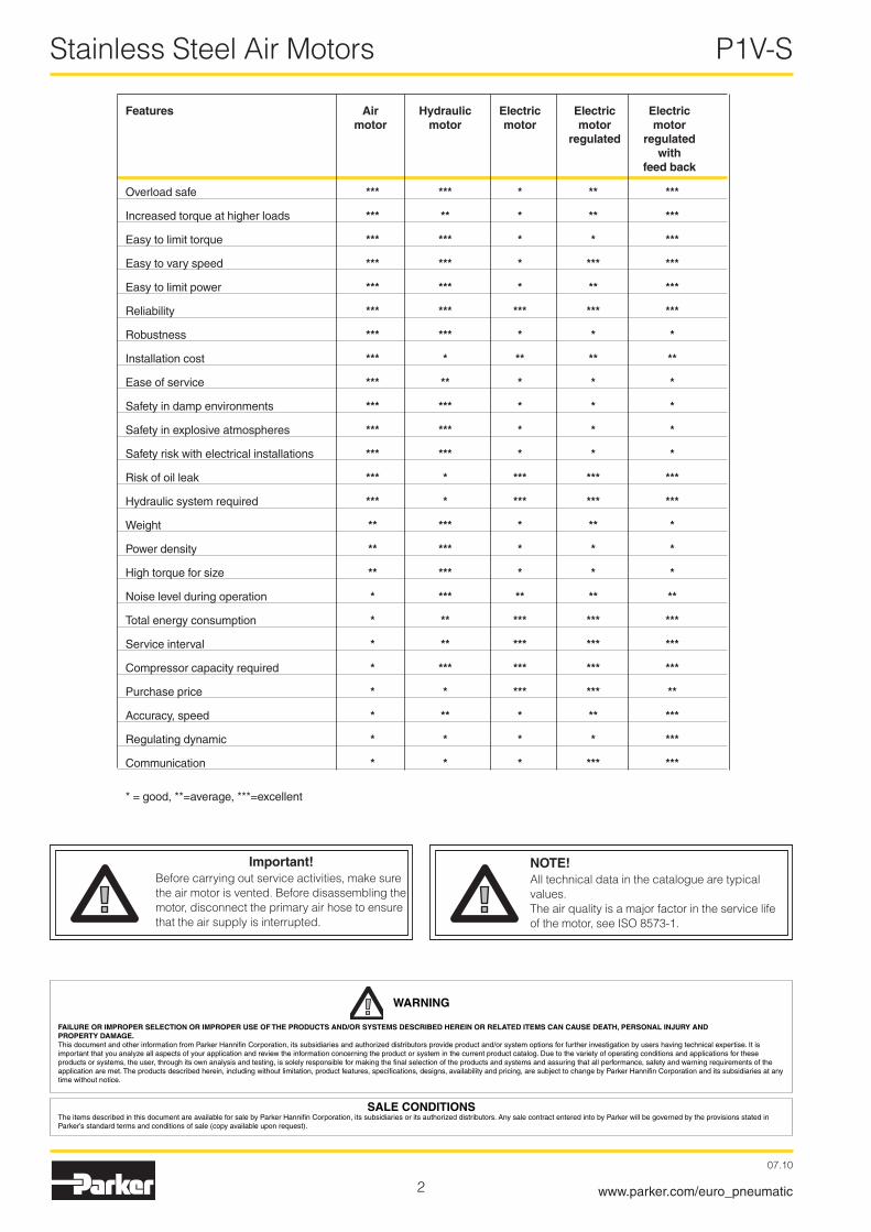
Features Air Hydraulic Electric Electric Electric motor motor motor motor motor regulated regulated with feed back
Overload safe *** *** * ** ***
Increased torque at higher loads *** ** * ** ***
Easy to limit torque *** *** * * ***
Easy to vary speed *** *** * *** ***
Easy to limit power *** *** * ** ***
Reliability *** *** *** *** ***
Robustness *** *** * * *
Installation cost *** * ** ** **
Ease of service *** ** * * *
Safety in damp environments *** *** * * *
Safety in explosive atmospheres *** *** * * *
Safety risk with electrical installations *** *** * * *
Risk of oil leak *** * *** *** ***
Hydraulic system required *** * *** *** ***
Weight ** *** * ** *
Power density ** *** * * *
High torque for size ** *** * * *
Noise level during operation * *** ** ** **
Total energy consumption * ** *** *** ***
Service interval * ** *** *** ***
Compressor capacity required * *** *** *** ***
Purchase price * * *** *** **
Accuracy, speed * ** * ** ***
Regulating dynamic * * * * ***
Communication * * * *** ***
* = good, **=average, ***=excellent
3
Stainless Steel Air Motors P1V-S
07.10
www.parker.com/euro_pneumatic
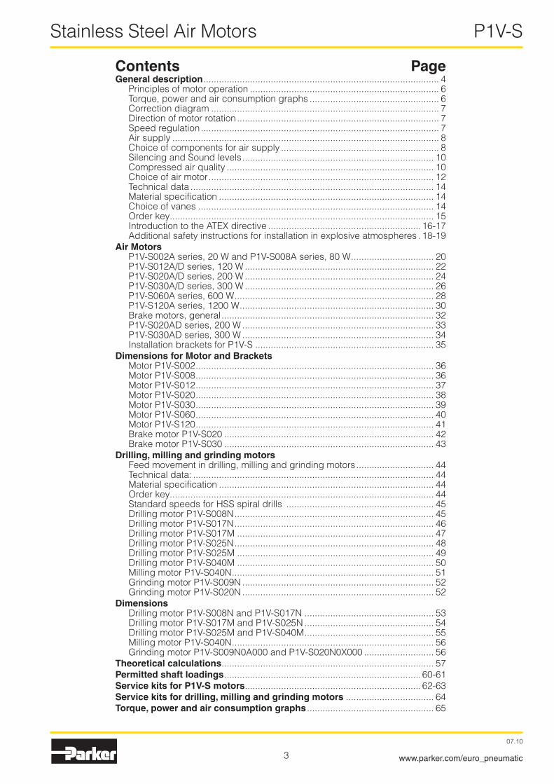
Contents PageGeneral description ........................................................................................... 4
Principles of motor operation ......................................................................... 6Torque, power and air consumption graphs .................................................. 6Correction diagram ........................................................................................ 7Direction of motor rotation .............................................................................. 7Speed regulation ............................................................................................ 7Air supply ....................................................................................................... 8Choice of components for air supply ............................................................. 8Silencing and Sound levels .......................................................................... 10Compressed air quality ................................................................................ 10Choice of air motor ....................................................................................... 1�Technical data .............................................................................................. 14Material specification ................................................................................... 14Choice of vanes ........................................................................................... 14Order key...................................................................................................... 15Introduction to the ATEX directive ........................................................... 16-17Additional safety instructions for installation in explosive atmospheres . 18-19
Air MotorsP1V-S00�A series, �0 W and P1V-S008A series, 80 W ................................ �0P1V-S01�A/D series, 1�0 W ......................................................................... ��P1V-S0�0A/D series, �00 W ......................................................................... �4P1V-S030A/D series, 300 W ......................................................................... �6P1V-S060A series, 600 W ............................................................................. �8P1V-S1�0A series, 1�00 W ........................................................................... 30Brake motors, general .................................................................................. 3�P1V-S0�0AD series, �00 W .......................................................................... 33P1V-S030AD series, 300 W .......................................................................... 34Installation brackets for P1V-S ..................................................................... 35
Dimensions for Motor and BracketsMotor P1V-S00� ............................................................................................ 36Motor P1V-S008 ............................................................................................ 36Motor P1V-S01� ............................................................................................ 37Motor P1V-S0�0 ............................................................................................ 38Motor P1V-S030 ............................................................................................ 39Motor P1V-S060 ............................................................................................ 40Motor P1V-S1�0 ............................................................................................ 41Brake motor P1V-S0�0 ................................................................................. 4�Brake motor P1V-S030 ................................................................................. 43
Drilling, milling and grinding motorsFeed movement in drilling, milling and grinding motors .............................. 44Technical data: ............................................................................................. 44Material specification ................................................................................... 44Order key...................................................................................................... 44Standard speeds for HSS spiral drills ......................................................... 45Drilling motor P1V-S008N ............................................................................. 45Drilling motor P1V-S017N ............................................................................. 46Drilling motor P1V-S017M ............................................................................ 47Drilling motor P1V-S0�5N ............................................................................. 48Drilling motor P1V-S0�5M ............................................................................ 49Drilling motor P1V-S040M ............................................................................ 50Milling motor P1V-S040N .............................................................................. 51Grinding motor P1V-S009N .......................................................................... 5�Grinding motor P1V-S0�0N .......................................................................... 5�
DimensionsDrilling motor P1V-S008N and P1V-S017N .................................................. 53Drilling motor P1V-S017M and P1V-S0�5N .................................................. 54Drilling motor P1V-S0�5M and P1V-S040M .................................................. 55Milling motor P1V-S040N .............................................................................. 56Grinding motor P1V-S009N0A000 and P1V-S0�0N0X000 ........................... 56
Theoretical calculations .................................................................................. 57Permitted shaft loadings ............................................................................ 60-61Service kits for P1V-S motors .................................................................... 6�-63Service kits for drilling, milling and grinding motors .................................. 64Torque, power and air consumption graphs ................................................. 65
4
Stainless Steel Air Motors P1V-S
07.10
www.parker.com/euro_pneumatic
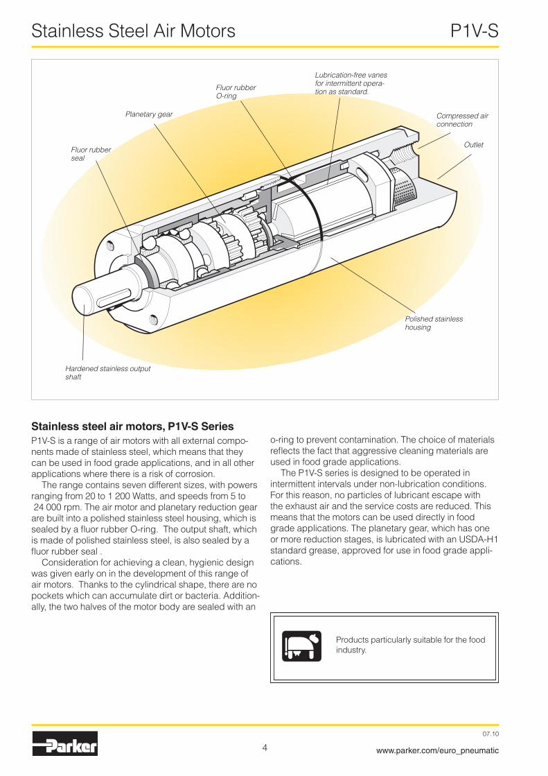
Stainless steel air motors, P1V-S SeriesP1V-S is a range of air motors with all external compo-nents made of stainless steel, which means that they can be used in food grade applications, and in all other applications where there is a risk of corrosion.
The range contains seven different sizes, with powers ranging from �0 to 1 �00 Watts, and speeds from 5 to �4 000 rpm. The air motor and planetary reduction gear are built into a polished stainless steel housing, which is sealed by a fluor rubber O-ring. The output shaft, which is made of polished stainless steel, is also sealed by a fluor rubber seal .
Consideration for achieving a clean, hygienic design was given early on in the development of this range of air motors. Thanks to the cylindrical shape, there are no pockets which can accumulate dirt or bacteria. Addition-ally, the two halves of the motor body are sealed with an
Fluor rubber seal
Planetary gear
Fluor rubber O-ring
Lubrication-free vanes for intermittent opera-tion as standard.
Compressed air connection
Outlet
Polished stainless housing
Hardened stainless output shaft
o-ring to prevent contamination. The choice of materials reflects the fact that aggressive cleaning materials are used in food grade applications.
The P1V-S series is designed to be operated in intermittent intervals under non-lubrication conditions. For this reason, no particles of lubricant escape with the exhaust air and the service costs are reduced. This means that the motors can be used directly in food grade applications. The planetary gear, which has one or more reduction stages, is lubricated with an USDA-H1 standard grease, approved for use in food grade appli-cations.
Products particularly suitable for the food industry.

5
Stainless Steel Air Motors P1V-S
07.10
www.parker.com/euro_pneumatic
Air motors have much smaller installation dimensions than corresponding electric motors.
Air motors can be loaded until they stall, without damage. They are designed to be able to withstand the toughest heat, vibration, impact etc.
The weight of an air motor is several times less than corre-sponding electric motors.
Air motors can be used in the harshest environments. Most P1V-S motors are ATEX certified.
The shape, design and non-lubricated operation allow the motor to be suitable for use in the food industry.
Air motors can be stopped and started continually without damage.
The simple design principle of air motors makes them very easy to service.
The motors are reversible as standard.
The reliability of air motors is very high, thanks to the design and the low number of moving parts.
The choice of materials means that they can be used in damp and aggressive environments.

6
Stainless Steel Air Motors P1V-S
07.10
www.parker.com/euro_pneumatic
Principles of motor operation
There are a number of designs of air motors. Parker Hannifin has chosen to use the vane rotor design, because of its simple design and reliable operation. The small external dimensions of vane motors make them suitable for all applications. The complete unit consists of a motor built together with a plan-etary reduction gear to give the required speed and torque at the output shaft.
The design of a vane air motor consists of a rotor which incorporates a given number of vanes all enclosed within a cylinder. The cylinder will include three ports; an inlet pressure port, an exhaust port and a residual port. Reliable starting is ensured by the fact that the inlet air presses the vanes against the cylinder wall prior to rotation. During operation, the vanes are pressed outwards by centrifugal force. The air pressure always acts at right angles to the vane surface, which means that the available torque is determined by the surface area of the vanes and by the air pressure. As each vane reached it’s lowest point air is released through the exhaust port. As the rotation continues air may be trapped and compressed between vanes. This compressed air is released through the residual port. The residual port doubles as the pressure port when the motor is operated in the reverse direction.
Inlet
Inlet, left Residual outlet Inlet, right
1 Rotor cylinder� Rotor3 Vanes4 End piece with bearing
The performance characteristics of each motor are shown in a family of curves as above, from which torque, power and air consumption can be read off as a function of speed. Power is zero when the motor is stationary and also when running at free speed (100%) with no load. Maximum power (100%) is normally developed when the motor is braked to approximately half the free speed (50%).
Torque at free speed is zero, but increases as soon as a load is applied, rising linearly until the motor stalls. As the motor can stop with the vanes in various positions, it is not possible to specify an exact starting torque. However, a minimum starting torque is shown in all tables.
Air consumption is greatest at free speed, and decreases with decreasing speed, as shown in the above diagram.
Torque, power and air consumption graphs
1
2
3
Outlet Outlet
4 3 1 2 4
Outlet
4020 60 80 100
160
120
140
200
180
100
100
20
40
60
80
20
40
60
80M
QP
Q [%], P [%]M [%]
n [%]
Possible working range of motor.
Optimum working range of motor.
Higher speeds = more vane wearLower speeds with high torque = more gearbox wear
The curve is for 6 barP = power Q = air consumption M = torque n = speed
Please refer to the curve on page 65 for these pressures:3, 4, 5, 6 and 7 bar

7
Stainless Steel Air Motors P1V-S
07.10
www.parker.com/euro_pneumatic
All catalogue data and curves are specified at a supply pres-sure of 6 bar (in the inlet port). This diagram shows the effect of pressure on speed, torque, power and air consumption.
Start off on the curve at the pressure used and then look up to the lines for power, torque, air consumption or speed. Read off the correction factor on the Y axis for each curve and multiply this by the specified catalogue data in the table or data read from the torque and power graphs.
Example: at 4 bar supply pressure, the power is only 0,55 x power at 6 bar supply pressure.
This example shows how rapidly the power rating of a motor decreases as the supply pressure is reduced. Therefore, it is critical to ensure that the proper pressure is supplied at the inlet port of the motor.
Direction of motor rotation
The most common way to reduce the speed of a motor is to install a flow control in the air inlet. When the motor is used in applications where it must reverse and it is necessary to restrict the speed in both directions, flow controls with integral non-return function should be used in both directions. Restric-tion may also be applied to the main outlet which will control the speed in both directions.
Inlet throttling
If the inlet air is restricted, the air supply is restricted and the free speed of the motor falls, but there is full pressure on the vanes at low speeds. This means full torque is available from the motor at low speed, despite the low air flow.
Since the torque curve becomes “steeper”, this also means that we get a lower torque at any given speed than would be developed at full air flow.
Pressure regulation
The speed and torque can also be regulated by installing a pressure regulator in the inlet pipe. When the motor is constantly supplied with air at lower pressure and the motor is braked, it develops a lower torque on the output shaft.
In brief: Inlet throttling gives reduced speed in one direction but maintains torque when braked. The torque curve becomes steeper. A restriction in the main inlet gives reduced speed in both directions but maintains torque when braked. The torque curve becomes steeper. Pressure regulation in the inlet cuts torque when the motor is braked, and also reduces speed. The torque curve is moved parallel.
P = power Q = air consumption M = torque n = speed
Speed regulationThrottling
Supply throttling, nonreversible motor.
Outlet throttling.
Supply throttling, reversible motor.
Pressure regulation at motor inlet.
Correction diagram
n = f (p)
p [bar]
Q = f (p)M = f (p)P = f (p)
0,4
0,3
0,5
0,6
0,7
0,8
0,9
1,0
1,1
1,2
1,3
3 4 5 6 7
Correction factor
M
M Torque curve change caused by throttling.
Torque curve change caused by pressure change.
The direction of rotation of reversible motors is controlled by supplying inlet L or inlet R with compressed air. Air motors can be stopped and started continually without damage.
As the motor begins to rotate air is trapped between the vanes and is compressed. This air is exhausted through the exhaust port. As the rotor continues it’s rotation, trapped air is compressed and exhausted through the residual port. If this air is not exhausted, the motor will be braked and maximum power will not be obtained.
Main outlet Main outlet
Residual outlet
Residual-outlet
Inlet, counter clockwise
Inlet, clockwise

8
Stainless Steel Air Motors P1V-S
07.10
www.parker.com/euro_pneumatic
Air supply
Shut-off, filtering, pressure regulation and control valve
Reversible motor with 5/3 control valve
Reversible motor with two 3/� control valves
13
2
15
3 24
13
2 13
2
The table can be used as follows:If you are using only one motor with each air treatment unit and valve, simply follow the table. If you are using more than one motor with the same air treatment unit: read the table values for selecting the air treatment unit and add them together, and select a suitable air treatment unit from the table showing air flows per treatment unit. Then read the values for selecting the valve from the bottom of the table, and select a suitable valve from the table showing air flows per valve family.
The air treatment units have the following flows in Nl/Min at 7,5 bar supply pressure and 0,8 bar pressure drop
FRL series Air flow in Nl/Min
P3H, Moduflex FRL, 40 Series, G1/4 550P3K, Moduflex FRL, 60 Series, G1/� 1310P3M, Moduflex FRL, 80 Series, G1 �770Standard series FRL, G11/� 9�00Stainless series FRL PF, G1/4 530Stainless series FRL PF, G1/� 1480
Valve series with respective flows in Nl/minute
Valve series Qn in Nl/Min
Valvetronic Solstar 33Interface PS1 100Adex A05 173Moduflex size 1, (� x 3/�) ��0Valvetronic PVL-B 5/3 closed centre, 6 mm push in �90Moduflex size 1, (4/�) 3�0B43 Manual and mechanical 340Valvetronic PVL-B � x �/3, 6 mm push in 350Valvetronic PVL-B 5/3 closed centre, G1/8 370Compact Isomax DX0� 385Valvetronic PVL-B � x 3/� G1/8 440Valvetronic PVL-B 5/�, 6 mm push in 450Valvetronic PVL-B 5/3 vented centre, 6 mm push in 450Moduflex size �, (� x 3/�) 450Flowstar P�V-A 5�0Valvetronic PVL-B 5/3 vented centre, G1/8 540Valvetronic PVL-B 5/�, G1/8 540Valvetronic PVL-C � x 3/�, 8 mm push in 540Adex A1� 560Valvetronic PVL-C � x 3/� G1/8 570Compact Isomax DX01 585VIKING Xtreme P�LAX 660Valvetronic PVL-C 5/3 closed centre, 8 mm push in 700Valvetronic PVL-C 5/3 vented centre, G1/4 700B3-Series 780Valvetronic PVL-C 5/3 closed centre, G1/4 780Moduflex size �, (4/�) 800Valvetronic PVL-C 5/�, 8 mm push in 840Valvetronic PVL-C 5/3 vented centre, 8 mm push in 840Valvetronic PVL-C 5/�, G1/4 840Flowstar P�V-B 1090ISOMAX DX1 1150B53 Manual and mechanical 1160B4-Series 1170VIKING Xtreme P�LBX 1�90B5-Series, G1/4 1440Airline Isolator Valve VE��/�3 1470ISOMAX DX� �330VIKING Xtreme P�LCX, G3/8 �460VIKING Xtreme P�LDX, G1/� �660ISOMAX DX3 4050Airline Isolator Valve VE4�/43 55�0Airline Isolator Valve VE8�/83 13680
13
2
1 m 2 m
Min 7,5 bar
6,7 bar6 bar
The air supplying the motor must be filtered and regulated. irectional valves are needed to control the pressurized air which will cause the motor to rotate. These valves can be equipped with several means of actuation, such as electric, manual or pneumatic control. When the motor is used in a non-reversible application, it is sufficient to use a �/� or 3/� valve for supply. Either one 5/3 or two 3/� valves are needed for a reversible motor, to ensure that the motor gets its compressed air and the residual outlet is vented. A flow control can be installed in the inlet pipe to regulate the motor speed if the motor is not used as a reversible motor. One flow control with by-pass is needed to regulate each direction of rotation if the motor is used as a reversible motor. The built-in check valve will then allow air from the residual air outlet to escape through the outlet port in the control valve.
The compressed air supply must have sufficiently large pipes and valves to give the motor maximum power. The motor needs 6 bar at the supply port all the time. A reduction of pressure to 5 bar reduces the power developed to 77%, and to 55% at 4 bar.
Choice of components for air supplySince the supply pressure at the air motor inlet port is of considerable importance for obtaining the power, speed and torque quoted in the catalogue, the recommendations below should be observed. The following data must be complied with:Supply pressure to air treatment unit: Min 7,5 barGauge pressure: 6,7 barPipe length between air treatment unit and valve: Max 1 mPipe length between valve and air motor: Max � mThe pressure drop through air treatment unit - pipe - valve - pipe means that 6 bar pressure is obtained at the motor inlet port. Please refer to the correction diagram on page 7, which shows what lower supply pressure means for power, speed and torque.

9
Stainless Steel Air Motors P1V-S
07.10
www.parker.com/euro_pneumatic
Air motors
Air motor P1V-S002 P1V-S008 P1V-S012 P1V-S020 P1V-S030 P1V-S060 P1V-S120
Air flow required, Nl/s 1,7 3,8 5,0 6,3 8,0 14,5 �7Air flow required, Nl/min 10� �30 300 380 480 870 16�0Min. internal diameter of pipe, mm 4 4 6 10 10 1� 19
Choice of air treatment unit: recommended min. air flow in litres/minute at 7,5 bar air supply and 0,8 bar pressure drop 110 255 330 420 530 960 1780
Choice of valve: recommended min. air flow in Qn in litres/minute (Qn is the flow through the valve at 6 bar supply pressure and 1 bar pressure drop over the valve).
123 280 360 440 660 1080 2160
Drilling motors
Drilling motor P1V-S008 P1V-S017 P1V-S025 P1V-S040
Air flow required, Nl/s 3,8 5,0 6,3 8,0Air flow required, Nl/min �30 300 380 480Min. internal diameter of pipe, mm 4 6 6 10
Choice of air treatment unit: recommended min. air flow in litres/minute at 7,5 bar air supply and 0,8 bar pressure drop 255 330 420 530
Choice of valve: recommended min. air flow in Qn in litres/minute (Qn is the flow through the valve at 6 bar supply pressure and 1 bar pressure drop over the valve).
280 360 440 580
Grinding and milling motors
Motor Grinding Grinding Milling P1V-S009 P1V-S020 P1V-S040
Air flow required, Nl/s �,0 6,3 8,0Air flow required, Nl/min 1�0 380 480Min. internal diameter of pipe, mm 4 6 10
Choice of air treatment unit: recommended min. air flow in litres/minute at 7,5 bar air supply and 0,8 bar pressure drop 135 420 530
Choice of valve: recommended min. air flow in Qn in litres/minute (Qn is the flow through the valve at 6 bar supply pressure and 1 bar pressure drop over the valve).
145 440 580
10
Stainless Steel Air Motors P1V-S
07.10
www.parker.com/euro_pneumatic
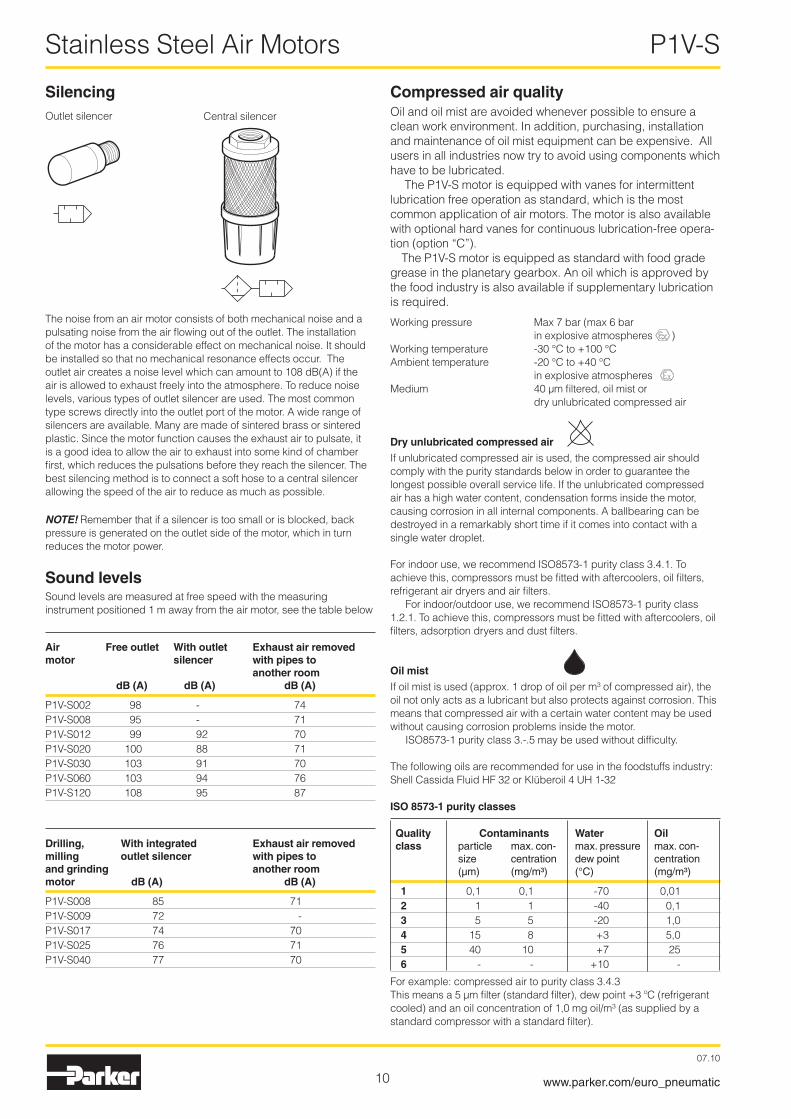
The noise from an air motor consists of both mechanical noise and a pulsating noise from the air flowing out of the outlet. The installation of the motor has a considerable effect on mechanical noise. It should be installed so that no mechanical resonance effects occur. The outlet air creates a noise level which can amount to 108 dB(A) if the air is allowed to exhaust freely into the atmosphere. To reduce noise levels, various types of outlet silencer are used. The most common type screws directly into the outlet port of the motor. A wide range of silencers are available. Many are made of sintered brass or sintered plastic. Since the motor function causes the exhaust air to pulsate, it is a good idea to allow the air to exhaust into some kind of chamber first, which reduces the pulsations before they reach the silencer. The best silencing method is to connect a soft hose to a central silencer allowing the speed of the air to reduce as much as possible.
NOTE! Remember that if a silencer is too small or is blocked, back pressure is generated on the outlet side of the motor, which in turn reduces the motor power.
Sound levelsSound levels are measured at free speed with the measuring instrument positioned 1 m away from the air motor, see the table below
Air Free outlet With outlet Exhaust air removed motor silencer with pipes to another room dB (A) dB (A) dB (A)
P1V-S00� 98 - 74P1V-S008 95 - 71P1V-S01� 99 9� 70P1V-S0�0 100 88 71P1V-S030 103 91 70P1V-S060 103 94 76P1V-S1�0 108 95 87
Drilling, With integrated Exhaust air removed milling outlet silencer with pipes to and grinding another room motor dB (A) dB (A)
P1V-S008 85 71P1V-S009 7� - P1V-S017 74 70 P1V-S0�5 76 71 P1V-S040 77 70
Outlet silencer
Compressed air qualityOil and oil mist are avoided whenever possible to ensure a clean work environment. In addition, purchasing, installation and maintenance of oil mist equipment can be expensive. All users in all industries now try to avoid using components which have to be lubricated.
The P1V-S motor is equipped with vanes for intermittent lubrication free operation as standard, which is the most common application of air motors. The motor is also available with optional hard vanes for continuous lubrication-free opera-tion (option “C”).
The P1V-S motor is equipped as standard with food grade grease in the planetary gearbox. An oil which is approved by the food industry is also available if supplementary lubrication is required.
Working pressure Max 7 bar (max 6 bar in explosive atmospheres )Working temperature -30 °C to +100 °CAmbient temperature -�0 °C to +40 °C in explosive atmospheresMedium 40 µm filtered, oil mist or dry unlubricated compressed air
Dry unlubricated compressed air
If unlubricated compressed air is used, the compressed air should comply with the purity standards below in order to guarantee the longest possible overall service life. If the unlubricated compressed air has a high water content, condensation forms inside the motor, causing corrosion in all internal components. A ballbearing can be destroyed in a remarkably short time if it comes into contact with a single water droplet.
For indoor use, we recommend ISO8573-1 purity class 3.4.1. To achieve this, compressors must be fitted with aftercoolers, oil filters, refrigerant air dryers and air filters.
For indoor/outdoor use, we recommend ISO8573-1 purity class 1.�.1. To achieve this, compressors must be fitted with aftercoolers, oil filters, adsorption dryers and dust filters.
Oil mist
If oil mist is used (approx. 1 drop of oil per m³ of compressed air), the oil not only acts as a lubricant but also protects against corrosion. This means that compressed air with a certain water content may be used without causing corrosion problems inside the motor.
ISO8573-1 purity class 3.-.5 may be used without difficulty.
The following oils are recommended for use in the foodstuffs industry: Shell Cassida Fluid HF 3� or Klüberoil 4 UH 1-3�
ISO 8573-1 purity classes
Quality Contaminants Water Oil class particle max. con- max. pressure max. con- size centration dew point centration (µm) (mg/m³) (°C) (mg/m³)
1 0,1 0,1 -70 0,01 2 1 1 -40 0,1 3 5 5 -�0 1,0 4 15 8 +3 5,0 5 40 10 +7 �5 6 - - +10 -
For example: compressed air to purity class 3.4.3This means a 5 µm filter (standard filter), dew point +3 ºC (refrigerant cooled) and an oil concentration of 1,0 mg oil/m³ (as supplied by a standard compressor with a standard filter).
SilencingCentral silencer

11
Stainless Steel Air Motors P1V-S
07.10
www.parker.com/euro_pneumatic
Service interval
The first service is due after approximately 500 hours of operation. After the first service, the service interval is determined by the degree of vane wear*. The table below shows new dimensions and the minimum dimensions of worn vanes.
Continuous lubrication-free operation of motors equipped with hard vanes (option C)
Duty cycle : ContinuousFiltration 40 µm : 750 hours of operation*Filtration 5 µm : 1000 hours of operation*
CE markingThe air motors are supplied as “Components for installation” – the installer is responsible for ensuring that the motors are installed safely in the overall system. Parker Pneumatic guarantees that its products are safe, and as a supplier of pneumatic equipment we ensure that the equipment is designed and manufactured in accordance with the applicable EU directive.
Most of our products are classed as components as defined by various directives, and although we guarantee that the components satisfy the fundamental safety requirements of the directives to the extent that they are our responsibility, they do not usually carry the CE mark. Nevertheless, most P1V-S motors carry the CE mark because they are ATEX certified (for use in explosive atmospheres).
The following are the currently applicable directives:• Machinery Directive(essential health and safety requirements
relating to the design and structure of machines and safety components)
• EMC Directive
• Simple Pressure Vessels Directive
• Low Voltage Directive
• ATEX Directive (ATEX = ATmosphere EXplosive)
X
* The specified hours of operation apply when the motor is running at the speed corresponding to maximum power (load speed). This is approximately half free speed.If the motor operates at higher speeds, the service interval is shorter.If the motor operates at lower speeds, the service interval is longer.
Air motor Dimensions on new vanes X(mm), type of vanes
Standard Z C MP1V-S002 3,3 – – –P1V-S008 4,3 – – –P1V-S012 4,� 4,� 4,� 4,�P1V-S020 6,5 6,0 6,0 6,0P1V-S030 6,8 6,� 6,8 6,�P1V-S060 9,0 9,0 9,0 9,0P1V-S120 14,7 14,0 14,0 14,0
Air motor Minimum dimensions on vane X (mm), type of vanes
Standard Z C MP1V-S002 3,0 – – –P1V-S008 4,0 – – –P1V-S012 3,3 3,3 3,3 3,3P1V-S020 5,8 5,3 5,3 5,3P1V-S030 6,0 5,� 6,0 5,�P1V-S060 6,0 6,0 6,0 6,0P1V-S120 14,� 13,5 13,5 13,5
Drilling, milling and grinding motor
New dimensions X(mm)
Minimum dimensions X (mm)
P1V-S008 4,3 4,0P1V-S017 4,� 3,3P1V-S025 6,5 5,8P1V-S040 6,8 6,0
The following normal service intervals should be applied to in order to guarantee problem-free operation in air motors working continuously at load speeds*.
Intermittent lubrication-free operation of motors with standard vanes
Duty cycle : 70%Max. duration of intermittent use : 15 minutesFiltration 40 µm : 750 hours of operation*Filtration 5 µm : 1 000 hours of operation*
Continuous operation of motors with standard vanes, with lubri-cation
Duty cycle : ContinuousQuantity of oil : 1 drop per m³ of airFiltration 40 µm : 1 000 hours of operation*Filtration 5 µm : � 000 hours of operation*
NOTE! After 1000 hours of operation, the grease in the planetary gearbox must be changed

1�
Stainless Steel Air Motors P1V-S
07.10
www.parker.com/euro_pneumatic
The motor to be used should be selected by starting with the torque needed at a specific shaft speed. In other words, to choose the right motor, you have to know the required speed and torque. Since maximum power is reached at half the motor’s free speed, the motor should be chosen so that the oprating point is as close as possible to the maximum power of the motor.
The design principle of the motor means that higher torque is generated when it is braked, which tends to increase the speed, etc. This means that the motor has a kind of speed self-regulation function built in.
Use the above graph to choose the correct motor size. The graph contains the points for the maximum torque of each motor at maximum output. Add your operating point to the graph, then select a marked point above and to the right of your point.
Then use the correct working diagram of the chosen motor to get more detailed technical data. Always select a motor whose requisite technical data are in the shaded area. Also use the correction diagram to find out what operation with different supply pressures would mean for the motor.
Tip: Select a motor which is slightly too fast and powerful, then regulate its speed and torque with a pressure regulator and/or throttle to achieve the optimum working point.
Choice of air motor
101 202 303 505 100 200 300 500 1000 2000 5000 10000 200003000
0,1
0,2
0,3
0,5
0,05
5,0
1,0
10
100
2,0
20
3,0
30
50
3
1
1
1
11
1
1
2
2
2
4
2
2
2
2
3
3
3
3
53
4
4
4
64
4
5
5
5
7
5
6
6
6
8 6
7
9
9
7
8
13 1112 10
10
7
8
Torque at maximum power [Nm]
Speed at maximum power [rpm]

13
Stainless Steel Air Motors P1V-S
07.10
www.parker.com/euro_pneumatic
Air motors in diagram above 1 P1V-S00�A0130 � P1V-S00�A0095
Graphs for each motor, see page �1.
1 P1V-S008A0Q00 � P1V-S008A0700 3 P1V-S008A0190 4 P1V-S008A0130
Graphs for each motor, see page �1.
1 P1V-S01�A0N00, P1V-S01�D0N00 � P1V-S01�A0550, P1V-S01�D0550 3 P1V-S01�A0360, P1V-S01�D0360 4 P1V-S01�A0140, P1V-S01�D1400 5 P1V-S01�A0090, P1V-S01�D0090 6 P1V-S01�A0060, P1V-S01�D0060 7 P1V-S01�A0010, P1V-S01�D0010
Graphs for each motor, see page �3.
1 P1V-S0�0A0E50, P1V-S0�0D0E50 � P1V-S0�0A0460, P1V-S0�0D0460 3 P1V-S0�0A0�40, P1V-S0�0D0�40 4 P1V-S0�0A0140, P1V-S0�0D0140 5 P1V-S0�0A0070, P1V-S0�0D0070 6 P1V-S0�0A0035, P1V-S0�0D0035 7 P1V-S0�0A0018, P1V-S0�0D0018 8 P1V-S0�0A0011 9 P1V-S0�0A0006 10 P1V-S0�0A0005, P1V-S0�0D0005 11 P1V-S0�0A000� 1� P1V-S0�0A0001 13 P1V-S0�0A00005
Graphs for each motor, see page �5.
1 P1V-S030A0E50, P1V-S030D0E50 � P1V-S030A0460, P1V-S030D0460 3 P1V-S030A0�40, P1V-S030D0�40 4 P1V-S030A0140, P1V-S030D0140 5 P1V-S030A0060, P1V-S030D0060 6 P1V-S030A00�8, P1V-S030D00�8 7 P1V-S030A00�3 8 P1V-S030A0018, P1V-S030D0018 9 P1V-S030A0010 10 P1V-S030A0005, P1V-S030D0005
Graphs for each motor, see page �7.
1 P1V-S060A0E00 � P1V-S060A0400 3 P1V-S060A0�70 4 P1V-S060A0170 5 P1V-S060A007� 6 P1V-S060A0048 7 P1V-S060A0030 8 P1V-S060A0010
Graphs for each motor, see page �9.
1 P1V-S1�0A0800 � P1V-S1�0A0�70 3 P1V-S1�0A0110 4 P1V-S1�0A0078 5 P1V-S1�0A003� 6 P1V-S1�0A001�
Graphs for each motor, see page 31.
P1V-S002A
P1V-S008A
P1V-S012A
P1V-S020A
P1V-S030A
P1V-S060A
P1V-S120A
P1V-S030D
P1V-S020D
P1V-S012D
20 Watt
80 Watt
120 Watt
200 Watt
300 Watt
600 Watt
1200 Watt

14
Stainless Steel Air Motors P1V-S
07.10
www.parker.com/euro_pneumatic
Technical dataWorking pressure Max 7 bar (max 6 bar in explosive atmospheres)Working temperature -30 °C to +100 °CAmbient temperature -�0 °C to +40 °C in explosive atmospheresMedium 40 µm filtered, oil mist or dry unlubricated compressed air
Table and diagram dataAll values are typical values, with a tolerance of ±10%
OptionOther variants on request
Material specificationPlanetary gearbox for:P1V-S060A0010 /30 /48P1V-S1�0A001� /3� Stainless steel, X46Cr13
Planetary gearbox for last planet stage incl. installation flangeP1V-S0�0A0011 /06 P1V-S030A00�3 /10 Black oxidised steel (not stainless)
All other housings Stainless steel, X1�CrMoS17
Spindle* Hardened stainless steel, X�0Cr13Key* Hardened stainless steel X6CrNiMoTi17-1�-�External seal Fluor rubber, FPMInternal steel parts High grade steel (not stainless)Planetary gear grease USDA-h1 approved
* P1V-S0�0A0011/06 and P1V-S030A00�3/10Key and Shaft High grade steel (not stainless)Screws in housing in last planet stage Surface treated steel (not stainless)
Flange bracket Stainless steel, X1�CrMoS17Foot bracket Stainless steel, X5CrNi18Screws for bracket Stainless steel DIN A�
Choice of vanes0 = StandardStandard vanes = These motors are of the vane type for inter-mittent lubrication-free operation. They can operate 70% of the time for up to 15 minutes without lubrication. With lubrication, these motors can operation 100% of the time.
Z = Spring loaded (standard) vanesStandard vanes = These motors are of the vane type for inter-mittent lubrication-free operation. They can operate 70% of the time for up to 15 minutes without lubrication. With lubrication, these motors can operation 100% of the time.Spring loaded vanes = All vanes are spring loaded to ensure that they remain pressed against the cylinder when the motor stops. The spring loaded vane option also prevents the vanes from sliding down in their track if vibration is introduced. The spring loaded vanes therefore provide a higher starting torque, improved starting and low speed characteristics, because the leakage over the vanes is reduced to a minimum.
C = Vanes for continuous lubrication-free operationC vanes = This motor is equipped with vanes for continuous lubrication-free operation. (To obtain the longest possible service life, we recommend no oil in the air.)
M = Multi (combination of Z+C)C vanes = This motor is equipped with vanes for continuous lubrication-free operation. (To obtain the longest possible service life, we recommend no oil in the air.)Spring loaded vanes = All vanes are spring loaded to ensure that they remain pressed against the cylinder when the motor stops. The spring loaded vane option also prevents the vanes from sliding down in their track if vibration is introduced. The spring loaded vanes therefore provide a higher starting torque, improved starting and low speed characteristics, because the leakage over the vanes is reduced to a minimum.

15
Stainless Steel Air Motors P1V-S
07.10
www.parker.com/euro_pneumatic
P 1 V - S 0 2 0 A 0 E 5 0
Order key
Possible combinationsPlease refer to pages �0 to 34.
Function
A Keyed shaft, reversible
D Threaded shaft, reversible
Motor size
002 �0 W
008 80 W
012 1�0 W
020 �00 W
030 300 W
060 600 W
120 1�00 W
Optional functions
0 Standard
C* Continuous lubrication-free operation
Z* Spring loaded vanes
M* Multi: combination of C+Z
D** Standard with brake
E** Option C with brake
F** Option Z with brake
G** Option M with brake
* Not for P1V-S00� and P1V-S008
** Only for P1V-S0�0 and P1V-S030
Free speed per min
0005 5
001 10 999 9990
A00 10000 E00 14000 E50 14500 N00 ��000
Q00 �4000Air motor range
P1V-S Stainless vane motor
16
Stainless Steel Air Motors P1V-S
07.10
www.parker.com/euro_pneumatic
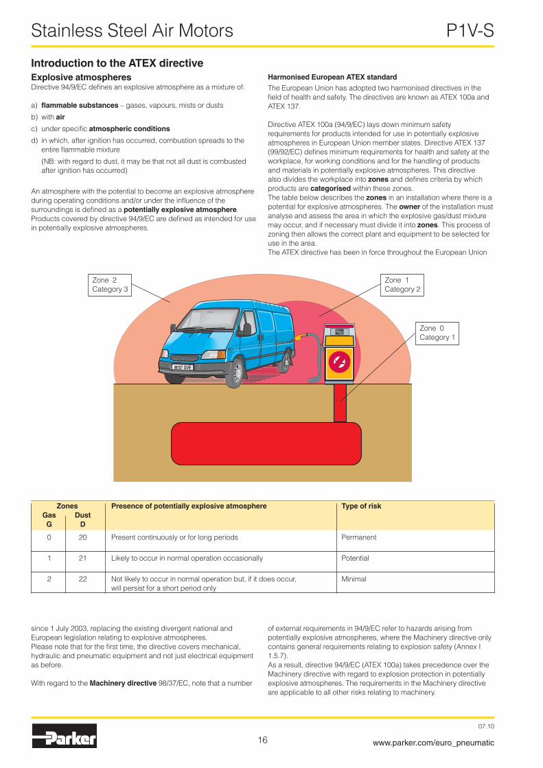
Introduction to the ATEX directiveExplosive atmospheresDirective 94/9/EC defines an explosive atmosphere as a mixture of:
a) flammable substances – gases, vapours, mists or dusts
b) with air
c) under specific atmospheric conditions
d) in which, after ignition has occurred, combustion spreads to the entire flammable mixture
(NB: with regard to dust, it may be that not all dust is combusted after ignition has occurred)
An atmosphere with the potential to become an explosive atmosphere during operating conditions and/or under the influence of the surroundings is defined as a potentially explosive atmosphere. Products covered by directive 94/9/EC are defined as intended for use in potentially explosive atmospheres.
Harmonised European ATEX standard
The European Union has adopted two harmonised directives in the field of health and safety. The directives are known as ATEX 100a and ATEX 137.
Directive ATEX 100a (94/9/EC) lays down minimum safety requirements for products intended for use in potentially explosive atmospheres in European Union member states. Directive ATEX 137 (99/9�/EC) defines minimum requirements for health and safety at the workplace, for working conditions and for the handling of products and materials in potentially explosive atmospheres. This directive also divides the workplace into zones and defines criteria by which products are categorised within these zones. The table below describes the zones in an installation where there is a potential for explosive atmospheres. The owner of the installation must analyse and assess the area in which the explosive gas/dust mixture may occur, and if necessary must divide it into zones. This process of zoning then allows the correct plant and equipment to be selected for use in the area. The ATEX directive has been in force throughout the European Union
since 1 July �003, replacing the existing divergent national and European legislation relating to explosive atmospheres.Please note that for the first time, the directive covers mechanical, hydraulic and pneumatic equipment and not just electrical equipment as before.
With regard to the Machinery directive 98/37/EC, note that a number
of external requirements in 94/9/EC refer to hazards arising from potentially explosive atmospheres, where the Machinery directive only contains general requirements relating to explosion safety (Annex I 1.5.7).As a result, directive 94/9/EC (ATEX 100a) takes precedence over the Machinery directive with regard to explosion protection in potentially explosive atmospheres. The requirements in the Machinery directive are applicable to all other risks relating to machinery.
Zones Presence of potentially explosive atmosphere Type of risk Gas Dust G D
0 �0 Present continuously or for long periods Permanent
1 �1 Likely to occur in normal operation occasionally Potential
� �� Not likely to occur in normal operation but, if it does occur, Minimal will persist for a short period only
Zone 1Category �
Zone �Category 3
Zone 0Category 1

17
Stainless Steel Air Motors P1V-S
07.10
www.parker.com/euro_pneumatic
Levels of protection for the various equipment categories
The various equipment categories must be capable of operating in accordance with the manufacturer’s operating specifications at defined levels of protection.
Level of Category Type of protection Operating specifications protec- Group Group tion I II
Very M1 Two independent means of protection or safety, ensuring that The equipment remains energised and high the equipment remains functional even in the event of two faults and functional even with an explosive occurring independently of each other atmosphere present
Very 1 Two independent means of protection or safety, ensuring that The equipment remains energised and high the equipment remains functional even in the event of two faults functional in zones 0, 1, � (G) and/or occurring independently of each other zones �0, �1, �� (D) High M� Protection suitable for normal operation and severe The equipment is de-energised in the operating conditions event of an explosive atmosphere High � Protection suitable for normal operation and frequent faults, or The equipment remains energised and func- equipment in which faults normally have to be taken into account tional in zones 1, � (G) and/or zones �1, �� (D) Normal 3 Protection suitable for normal operation The equipment remains energised and func- tional in zones � (G) and/or zones �� (D)
G = gas and D = dust
Temperature classes
Classification of flammable gases and vapours on the basis of ignition temperature
Group I II mines, combustible vapours other potentially explosive atmospheres (gases, dust)
Category M1 M2 1 2 3
Atmosphere* G D G D G D
Zone 0 �0 1 �1 � ��
Declaration of conformity
The product catalogues contain copies of the declaration of conformity demonstrating that the product meets the requirements of directive 94/9/EC.The declaration is only valid in conjunction with the instructions contained in the installation manual relating to the safe use of the product throughout its service life. The instructions relating to the conditions in the surrounding area are particularly important, as the certificate is invalidated if the instructions are found not to have been adhered to during operation of the product.If there is any doubt as to the validity of the certificate of conformity, contact Parker Hannifin customer service.
Temperature class Ignition temperature °C
T1 Over 450
T� (300) – 450
T3 (�00) – 300
T4 (135) – �00
T5 (100) – 135
T6 (85) - 100
Operation, installation and maintenance
The installation manual of the product contains instructions relating to the safe storage, handling, operation and servicing of the product.The manual is available in different languages, and can be downloaded from www.parker.com/euro_pneumatic.This document must be made accessible in a suitable place near where the product is installed. It is used as a reference for all personnel authorised to work with the product throughout its service life. We, the manufacturer, reserve the right to modify, extend or improve the installation manual in the interests of the users.
For more information about ATEX see EUs homepage: http://europa.eu.int/comm/enterprise/atex/
Definition of groups (EN 11�7-1)Group I Equipment intended for use in underground parts of mines as well as those parts of surface installations of such mines likely to be
endangered by flammable vapours and/or flammable dusts.Group II Equipment intended for use in other places exposed to explosive atmospheres.
18
Stainless Steel Air Motors P1V-S
07.10
www.parker.com/euro_pneumatic
Serious, even fatal, damage or injury may be caused by the hot moving parts of the P1V-S motors in the presence of explosive gas mixtures and concentrations of dust.
All installation, connection, commissioning, servicing and repair work on P1V-S motors must be carried out by qualified personnel taking account of the following• These instructions
• Notices on the motor
• All other planning documents, commissioning instructions and connection diagrams associated with the application.
• Provisions and requirements specific to the application
• Applicable national/international regulations (explosion protection, safety and accident prevention)
Real life applicationsP1V-S motors are designed to provide rotary movement in industrial applications, and should only be used in accord-ance with the instructions in the technical specifications in the catalogue, and within the operating range indicated on the motor housing. The motors meet the applicable standards and requirements of the Machinery Directive 94/9/EC (ATEX)
The motors must not be used as brakes in explosive atmospheres. Braking involves driving the motor against the direction of rotation for which the motor is supplied with compressed air. The motor is then operating as a compressor, and there is a corresponding increase in temperature.
The motors must not be used underground in mines suscep-tible to firedamp and/or combustible dust. The motors are intended for use in areas in which explosive atmospheres caused by gases, vapours or mists of combustible liquids, or air/dust mixtures may be expected to occur during normal use (infrequently)
Checklist Before using the motors in a potentially explosive atmosphere, you should check the following:
Do the motor specifications match the classification of the area of use in accordance with Directive 94/9/EG (previously ATEX 100a)• Equipment group
• Equipment category
• Zone
• Temperature class
• Max. surface temperature
1. When installing the motor, is it certain that there is no potentially explosive atmosphere, oil, acids, gases, vapours or radiation?
�. Is the ambient temperature as specified in the technical data in the catalogue at all times?
3. Is it certain that the P1V-S motor is adequately ventilated and that no additional heat is added (for example in the shaft connection)?
4. Are all the driven mechanical components ATEX certified?
Additional safety instructions for installation in explosive atmospheres
Installation requirements in potentially explosive at-mospheres• The temperature of the supply air must not exceed the ambient
temperature.
• The P1V-S may be installed in any position.
• An air treatment unit must be attached to the inlet of the P1V-S air motor.
• In a potentially explosive atmosphere, none of the motor ports may be blocked because this may cause an increase in temperature. The air from the port must be taken to the silencer or, preferably, outside the potentially explosive area.
• The P1V-S motor must be connected to ground at all times, through its support, a metallic tube or separate conductor.
• The outlet of the P1V-S motor must not open within a potentially explosive area, but must be passed to the silencer or, preferably, removed and released outside the potentially explosive area.
• The P1V-S motor may only drive units that are ATEX certified.
• Ensure that the motor is not exposed to forces greater than those permitted in accordance with the catalogue.
Measuring the temperature on the outside of the P1V-S motor (only when used in potentially explosive areas)During the commissioning process, it is essential to measure temperature increases at the indicated positions on the outside of the P1V-S motor.These measurements can be taken using standard thermom-eters.
Checking the motor during operation The motor must be kept clean on the outside, and a layer of dirt thicker than 5 mm must never be allowed to form.Strong solvents should not be used for cleaning, because they can cause the seal (material NBR/FPM) around the drive shaft to swell, potentially increasing the temperature.

19
Stainless Steel Air Motors P1V-S
07.10
www.parker.com/euro_pneumatic
For the P1V-S012, P1V-S020, P1V-S030 and P1V-S060 seriesThe temperature is measured on the metal surface next to the seal around the output shaft on all P1V-S01�, P1V-S0�0, P1V-S030 and P1V-S060 motors
II2 GD c IIC T6 (80 °C) X
II2 GD c IIC T5 (95 °C) XSeal
Planetary gearbox
Motor part
45
Planetary gearbox
Motor part
x
Marking of products
For all P1V-S012, P1V-S020, P1V-S030 and P1V-S060
For the P1V-S120
Communatuté Européenne = EU CE marking shows that as a manufacturer, Parker Hannifin meets the guidelines specified by the EU
Ex means that this product is intended for use in a potentially explosive area
II stands for the equipment group (I = mines and II = other places liable to be endangered)
2GD stands for equipment category 2G means the equipment can be used in zones 1 and � where there is a risk involving gas, vapour or mist of combustible liquids and 2D in zones �1 and �� where there is a risk involving dust . 2GD means the equipment can be used in zones 1, �, �1 and ��.
c Safe design (prEN 13463-5)
IIC Explosion group, P1V-S air motors are tested to the highest standards in terms of test gases, and can be installed in the presence of all gases without restric-tion.
T6 If equipment is in temperature class T6, the maximum surface temperature must not exceed 85 °C. (To guar-antee this, the product has been tested to ensure that the maximum is 80 °C. This provides a safety margin of 5 °K.)
T5 If equipment is in temperature class T5, the maximum surface temperature must not exceed 100 °C. (To guarantee this, the product has been tested to ensure that the maximum is 95 °C. This provides a safety margin of 5 °K.)
(80 °C) Maximum permitted surface temperature on the motor in atmospheres containing potentially explosive dust.
X Note special conditions
Test certificate number IBExU04ATEXB004 X from IBExU Institut für Sicherheitstechnik GmbH, D-09599 Freiberg, Germany
Motor x [mm]
P1V-S0�0A0011 133P1V-S0�0A0006 133 P1V-S030A00�3 146P1V-S030A0010 147,5
The maximum temperature is reached after approximately 1,5 hours of operation, and the difference in temperature between the motor and the ambient temperature must not exceed 40 °C.
If the temperature difference at the seal of a P1V-S012, P1V-S020, P1V-S030 or P1V-S060 exceeds 40 °C, you should stop the motor immediately and contact Parker Hannifin.
The following applies to the P1V-S120 series:The temperature is measured on the metal surface at a point 45 mm from the port end of the motor housing, on all P1V-S1�0.
Motors P1V-S020A0011, P1V-S020A0006, P1V-S030A0023 and P1V-S030A0010
The maximum temperature is reached after approximately 1,5 hours of operation, and the difference in temperature between the motor and the ambient temperature must not exceed 55 °C.
If the temperature difference at this point on a P1V-S120 exceeds 55 °C, you should stop the motor immediately and contact Parker Hannifin.

�0
Stainless Steel Air Motors P1V-S
07.10
www.parker.com/euro_pneumatic
NOTE! All technical data is based on a working pressure of 6 bar.
Data for reversible air motor with keyed shaft, P1V-S008A series
Max power Free Speed at Torque Min Air con- Conn. Min pipe Weight Order code speed max at max start sumption at ID power power torque max power kW rpm rpm Nm Nm l/s mm Kg
0,08 �4000 1�000 0,06 0,09 3,5 M8x0,75* 4 0,�� P1V-S008A0Q00
0,08 7000 3500 0,�� 0,33 3,5 M8x0,75* 4 0,�� P1V-S008A0700
0,08 1900 950 0,80 1,�0 3,5 M8x00,75* 4 0,�� P1V-S008A0190
0,08 1300 650 1,�0 1,80 3,5 M8x0,75* 4 0,�� P1V-S008A0130
* 3 push in nipples (F�8PMB6M8SP) for plastic pipe Ø6/4 suppliedNOTE! Not with vane options C, Z or M.The P1V-S00�A and P1V-S008A require oil mist for lubricating the gearbox.
NOTE! All technical data is based on a working pressure of 6 bar.
Installation brackets, see page 35
Dimensions, see page 36
Permitted shaft loadings, see page 60
Service kits, see page 62
Installation brackets, see page 35
Dimensions, see page 36
Permitted shaft loadings, see page 60
Service kits, see page 62
Data for reversible air motor with keyed shaft, P1V-S002A series
Max power Free Speed at Torque Min Air con- Conn. Min pipe Weight Order code speed max at max start sumption at ID power power torque max power kW rpm rpm Nm Nm l/s mm Kg
0,0� 1300 650 0,�9 0,44 1,7 M5 3 0,16 P1V-S002A0130
0,0� 950 475 0,40 0,60 1,7 M5 3 0,16 P1V-S002A0095
NOTE! Not with vane options C, Z or M.The P1V-S00�A and P1V-S008A require oil mist for lubricating the gearbox.

�1
Stainless Steel Air Motors P1V-S
07.10
www.parker.com/euro_pneumatic
400200 600 800 1000
5
10
15
20
0,2
0,4
0,6
0,8M
P
P1V-S002A0095M, torque [Nm] P, power [W]
P1V-S002A0130M, torque [Nm] P, power [W]
600300 900 1200 1500
5
10
15
20
0,2
0,4
0,6M
P
2000 4000 6000 8000 10000
20
40
60
80
0,1
0,2
0,3
0,4M
P
P1V-S008A0700M, torque [Nm] P, power [W]
P1V-S008A0N00M, torque [Nm] P, power [W]
4000 16000 24000
20
40
60
80
0,06
0,12M
P
400 800 1200 1600 2000
20
40
60
80
0,4
0,8
1,2
1,6
MP
P1V-S008A0190M, torque [Nm] P, power [W]
P1V-S008A0130M, torque [Nm] P, power [W]
300 600 900 1200 1500
20
40
60
80
0,6
1,2
1,8
2,4
MP
n, speed [rpm]
n, speed [rpm] n, speed [rpm] n, speed [rpm]
n, speed [rpm] n, speed [rpm]
Possible working range of motor.
Optimum working range of motor.
Higher speeds = more vane wearLower speeds with high torque = more gearbox wear

��
Stainless Steel Air Motors P1V-S
07.10
www.parker.com/euro_pneumatic
Data for reversible air motor with keyed shaft, P1V-S012A series
Max power Free Speed at Torque Min Air con- Conn. Min pipe Weight Order code speed max at max start sumption at ID power power torque max power kW rpm rpm Nm Nm l/s mm Kg
0,1�0 ��000 11000 0,10 0,15 5,0 G1/8 6 0,350 P1V-S012A0N00
0,1�0 5500 �750 0,4� 0,63 5,0 G1/8 6 0,350 P1V-S012A0550
0,1�0 3600 1800 0,64 0,95 5,0 G1/8 6 0,350 P1V-S012A0360
0,1�0 1400 700 1,64 �,40 5,0 G1/8 6 0,400 P1V-S012A0140
0,1�0 900 450 �,54 3,80 5,0 G1/8 6 0,400 P1V-S012A0090
0,1�0 600 300 3,8� 5,00* 5,0 G1/8 6 0,400 P1V-S012A0060
0,090 100 50 5,00* 5,00* 5,0 G1/8 6 0,450 P1V-S012A0010
* Max permitted torqueIn all P1V-S01� motors, torques exceeding 5 Nm may cause damage to the gearbox(e.g. when driving against a fixed stop or large oscillating weight)
Data for reversible air motor with threaded shaft, P1V-S012D series
Max power Free Speed at Torque Min Air con- Conn. Min pipe Weight Order code speed max at max start sumption at ID power power torque max power kW rpm rpm Nm Nm l/s mm Kg
0,1�0 ��000 11000 0,10 0,15 5,0 G1/8 6 0,350 P1V-S012D0N00
0,1�0 5500 �750 0,4� 0,63 5,0 G1/8 6 0,350 P1V-S012D0550
0,1�0 3600 1800 0,64 0,95 5,0 G1/8 6 0,350 P1V-S012D0360
0,1�0 1400 700 1,64 �,40 5,0 G1/8 6 0,400 P1V-S012D0140
0,1�0 900 450 �,54 3,80 5,0 G1/8 6 0,400 P1V-S012D0090
0,1�0 600 300 3,8� 5,00* 5,0 G1/8 6 0,400 P1V-S012D0060
0,090 100 50 5,00* 5,00* 5,0 G1/8 6 0,450 P1V-S012D0010
* Max permitted torqueIn all P1V-S01� motors, torques exceeding 5 Nm may cause damage to the gearbox(e.g. when driving against a fixed stop or large oscillating weight)
NOTE! All technical data is based on a working pressure of 6 bar.
NOTE! The P1V-S01�D with threaded shaft may be reversed, but when operated anticlockwise, there is a risk that the driven unit may disconnect if it is not locked properly.
Installation brackets, see page 35
Dimensions, see page 37
Permitted shaft loadings, see page 60
Service kits, see page 62
II2 GD c IIC T6 (80 °C) X
II2 GD c IIC T6 (80 °C) X

�3
Stainless Steel Air Motors P1V-S
07.10
www.parker.com/euro_pneumatic
2000 4000 6000
15
45
75
105
30
60
90
120
0,1
0,2
0,3
0,4
0,9
0,5
0,6
0,7
0,8M
P
P1V-S012A0550P1V-S012D0550M, torque [Nm] P, power [W]
1600800 2400 3200 4000
15
45
75
105
30
60
90
120
0,2
0,4
0,6
0,8
1,0
1,2
1,4
1,6
MP
600300 900 1200 1500
15
45
75
105
30
60
90
120
1,0
2,0
3,0
4,0
M P
400200 600 800 1000
15
45
75
105
30
60
90
120
1,25
2,50
3,75
5,00M
P
300150 450 600 750
15
45
75
105
30
60
90
120
2,0
4,0
6,0
8,0
M P
5025 75 100 125
15
45
75
105
30
60
90
120
5
10
15
20M
P
P1V-S012A0360P1V-S012D0360M, torque [Nm] P, power [W]
P1V-S012A0140P1V-S012D0140M, torque [Nm] P, power [W]
P1V-S012A0090P1V-S012D0090M, torque [Nm] P, power [W]
P1V-S012A0060P1V-S012D0060M, torque [Nm] P, power [W]
P1V-S012A0010P1V-S012D0010M, torque [Nm] P, power [W]
n, speed [rpm] n, speed [rpm]
n, speed [rpm] n, speed [rpm] n, speed [rpm]
n, speed [rpm]
P1V-S012A0N00P1V-S012D0N00M, torque [Nm] P, power [W]
n, speed [rpm]
4000 16000 24000
15
45
75
105
30
60
90
120
0,1
0,2M
P
Max permitted torque 5 Nm
Max permitted torque 5 Nm
Possible working range of motor.
Optimum working range of motor.
Higher speeds = more vane wearLower speeds with high torque = more gearbox wear

�4
Stainless Steel Air Motors P1V-S
07.10
www.parker.com/euro_pneumatic
Data for reversible air motor with keyed shaft, P1V-S020A series
Max power Free Speed at Torque Min Air con- Conn. Min pipe Weight Order code speed max at max start sumption at ID power power torque max power kW rpm rpm Nm Nm l/s mm Kg
0,�00 14500 7�50 0,�6 0,40 6,3 G1/8 10 0,700 P1V-S020A0E50
0,�00 4600 �300 0,80 1,�0 6,3 G1/8 10 0,750 P1V-S020A0460
0,�00 �400 1�00 1,60 �,40 6,3 G1/8 10 0,750 P1V-S020A0240
0,�00 1400 700 �,70 4,10 6,3 G1/8 10 0,850 P1V-S020A0140
0,�00 700 350 5,40 8,�0 6,3 G1/8 10 0,850 P1V-S020A0070
0,�00 350 160 1�,00 18,00 6,3 G1/8 10 0,850 P1V-S020A0035
0,100 180 90 10,50 15,00 4,5 G1/8 10 0,850 P1V-S020A0018
0,�00 110 55 33,00 49,50 6,3 G1/8 10 3,000 P1V-S020A0011
0,�00 60 30 7�,00 108,00* 6,3 G1/8 10 3,000 P1V-S020A0006
0,180 50 �5 �0,00* �0,00* 6,3 G1/8 10 0,950 P1V-S020A0005
0,180 �0 – �0,00* �0,00* 6,3 G1/8 10 0,950 P1V-S020A0002
0,180 10 – �0,00* �0,00* 6,3 G1/8 10 1,050 P1V-S020A0001
0,180 5 – �0,00* �0,00* 6,3 G1/8 10 1,050 P1V-S020A00005
* Max permitted torque
Data for reversible air motor with threaded shaft, P1V-S020D series
Max power Free Speed at Torque Min Air con- Conn. Min pipe Weight Order code speed max at max start sumption at ID power power torque max power kW rpm rpm Nm Nm l/s mm Kg
0,�00 14500 7�50 0,�6 0,40 6,3 G1/8 10 0,700 P1V-S020D0E50
0,�00 4600 �300 0,80 1,�0 6,3 G1/8 10 0,750 P1V-S020D0460
0,�00 �400 1�00 1,60 �,40 6,3 G1/8 10 0,750 P1V-S020D0240
0,�00 1400 700 �,70 4,10 6,3 G1/8 10 0,850 P1V-S020D0140
0,�00 700 350 5,40 8,�0 6,3 G1/8 10 0,850 P1V-S020D0070
0,�00 350 160 1�,00 18,00 6,3 G1/8 10 0,850 P1V-S020D0035
0,100 180 90 10,50 15,00 4,5 G1/8 10 0,850 P1V-S020D0018
0,180 50 �5 �0,00* �0,00* 6,3 G1/8 10 0,950 P1V-S020D0005
* Max permitted torque
NOTE! The P1V-S0�0D with threaded shaft may be reversed, but when operated anticlockwise, there is a risk that the driven unit may disconnect if it is not locked properly.
NOTE! All technical data is based on a working pressure of 6 bar.
Installation brackets, see page 35
Dimensions, see page 38
Permitted shaft loadings, see page 60
Service kits, see page 62
II2 GD c IIC T6 (80 °C) X
II2 GD c IIC T6 (80 °C) X

�5
Stainless Steel Air Motors P1V-S
07.10
www.parker.com/euro_pneumatic
P1V-S020A0E50P1V-S020D0E50M, torque [Nm] P, power [W]
P1V-S020A0460, P1V-S020D0460M, torque [Nm] P, power [W]
P1V-S020A0240P1V-S020D0240M, torque [Nm] P, power [W]
P1V-S020A0140P1V-S020D0140M, torque [Nm] P, power [W]
P1V-S020A0070P1V-S020D0070M, torque [Nm] P, power [W]
P1V-S020A0035P1V-S020D0035M, torque [Nm] P, power [W]
P1V-S020A0018P1V-S020D0018M, torque [Nm] P, power [W]
P1V-S020A0011
M, torque [Nm] P, power [W]
60003000 9000 12000 15000
25
75
125
175
50
100
150
200
0,15
0,30
0,45
0,60
M P
20001000 3000 4000 5000
25
75
125
175
50
100
150
200
0,4
0,8
1,2
1,6M
P
1000500 1500 2000 2500
25
75
125
175
50
100
150
200
0,75
1,50
2,25
3,00
M P
600300 900 1200 1500
25
75
125
175
50
100
150
200
1,5
3,0
4,5
6,0
M P
300150 450 600 750
25
75
125
175
50
100
150
200
3
6
9
12
M P
15075 225 300 375
25
75
125
175
50
100
150
200
6
12
18
24M
P
40 6020 80 100 140 160 200120 180
2,5
5,0
7,5
10,0
12,5
15,0
17,5
20,0
M
P
25
75
125
175
50
100
150
200
6030 90 120 150
25
75
125
175
50
100
150
200
15
30
45
60M
P
n, speed [rpm] n, speed [rpm] n, speed [rpm]
n, speed [rpm] n, speed [rpm] n, speed [rpm]
n, speed [rpm]20 40 60
25
75
125
175
50
100
150
200
50
100
150
M
P
P1V-S020A0006
M, torque [Nm] P, power [W]
n, speed [rpm]
P1V-S020A0005P1V-S020D0005M, torque [Nm] P, power [W]
2010 30 40 50
25
75
125
175
50
100
150
200
20
40
60
80 M
P
n, speed [rpm]2 4 6 8 10 12 14 16 18 20
25
75
125
175
50
100
150
200
20
40
60
80M
P
P1V-S020A0002
M, torque [Nm] P, power [W]
n, speed [rpm]
Max permitted torque 20 Nm
Max permitted torque 20 Nm
P1V-S020A0001P1V-S020A00005M, torque [Nm] P, power [W]
1P1V-S020A0001
P1V-S020A000051
2
2
3
3
4
4
5
5
6 7 8 9 10
30
90
150
60
120
180
20
40
60
MP
n, speed [rpm]
Max permitted torque 20 Nm
Possible working range of motor.
Optimum working range of motor.Higher speeds = more vane wearLower speeds with high torque = more gearbox wear
Max per-mitted torque 108 Nm
n, speed [rpm]

�6
Stainless Steel Air Motors P1V-S
07.10
www.parker.com/euro_pneumatic
Data for reversible air motor with keyed shaft, P1V-S030A series
Max power Free Speed at Torque Min Air con- Conn. Min pipe Weight Order code speed max at max start sumption at ID power power torque max power kW rpm rpm Nm Nm l/s mm Kg
0,300 14500 7�50 0,40 0,60 8,0 G1/4 10 1,000 P1V-S030A0E50
0,300 4600 �300 1,�0 1,90 8,0 G1/4 10 1,050 P1V-S030A0460
0,300 �400 1�00 �,40 3,60 8,0 G1/4 10 1,050 P1V-S030A0240
0,300 1400 700 4,10 6,10 8,0 G1/4 10 1,100 P1V-S030A0140
0,300 600 300 9,60 14,30 8,0 G1/4 10 1,150 P1V-S030A0060
0,300 �80 140 �0,50 �6,00 8,0 G1/4 10 1,150 P1V-S030A0028
0,300 �30 115 �4,00 36,00 8,0 G1/4 10 3,300 P1V-S030A0023
0,130 180 90 13,80 �1,00 4,7 G1/4 10 1,150 P1V-S030A0018
0,300 100 50 57,00 85,50 8,0 G1/4 10 3,300 P1V-S030A0010
0,�80 50 �5 36,00* 36,00* 8,0 G1/4 10 1,�50 P1V-S030A0005
* Max permitted torque
Data for reversible air motor with threaded shaft, P1V-S030D series
Max power Free Speed at Torque Min Air con- Conn. Min pipe Weight Order code speed max at max start sumption at ID power power torque max power kW rpm rpm Nm Nm l/s mm Kg
0,300 14500 7�50 0,40 0,60 8,0 G1/4 10 1,000 P1V-S030D0E50
0,300 4600 �300 1,�0 1,90 8,0 G1/4 10 1,050 P1V-S030D0460
0,300 �400 1�00 �,40 3,60 8,0 G1/4 10 1,050 P1V-S030D0240
0,300 1400 700 4,10 6,10 8,0 G1/4 10 1,100 P1V-S030D0140
0,300 600 300 9,60 14,30 8,0 G1/4 10 1,150 P1V-S030D0060
0,300 �80 140 �0,50 �6,00 8,0 G1/4 10 1,150 P1V-S030D0028
0,130 180 90 13,80 �1,00 4,7 G1/4 10 1,150 P1V-S030D0018
0,�80 50 �5 36,00* 36,00* 8,0 G1/4 10 1,�50 P1V-S030D0005
* Max permitted torque
NOTE! The P1V-S030D with threaded shaft may be reversed, but when operated anticlockwise, there is a risk that the driven unit may disconnect if it is not locked properly.
NOTE! All technical data is based on a working pressure of 6 bar.
Installation brackets, see page 35
Dimensions, see page 39
Permitted shaft loadings, see page 60
Service kits, see page 62
II2 GD c IIC T6 (80 °C) X
II2 GD c IIC T6 (80 °C) X

�7
Stainless Steel Air Motors P1V-S
07.10
www.parker.com/euro_pneumatic
P1V-S030A0E50P1V-S030D0E50M, torque [Nm] P, power [W]
P1V-S030A0460, P1V-S030D0460M, torque [Nm] P, power [W]
P1V-S030A0240P1V-S030D0240M, torque [Nm] P, power [W]
P1V-S030A0140P1V-S030D0140M, torque [Nm] P, power [W]
P1V-S030A0060P1V-S030D0060M, torque [Nm] P, power [W]
P1V-S030A0028P1V-S030D0028M, torque [Nm] P, power [W]
P1V-S030A0018P1V-S030D0018M, torque [Nm] P, power [W]
P1V-S030A0010
M, torque [Nm] P, power [W]
n, speed [rpm] n, speed [rpm] n, speed [rpm]
n, speed [rpm] n, speed [rpm] n, speed [rpm]
n, speed [rpm] n, speed [rpm]
60003000 9000 12000 15000
300
100
200
0,2
0,4
0,6
0,8M P
300
100
200
0,6
1,2
1,8
2,4M P
20001000 3000 4000 5000
300
100
200
1,0
2,0
3,0
4,0M P
1000500 1500 2000 2500
300
100
200
2,0
4,0
6,0
8,0M P
600300 900 1200 1500
300
100
200
5
10
15
20M
P
300150 450 600 750
300
100
200
10
20
30
40M P
100 300200
40 6020 80 100 140 160 200120 180
3
6
9
12
15
18
21
24M
P
300
100
200
P1V-S030A0005P1V-S030D0005M, torque [Nm] P, power [W]
n, speed [rpm]
300
100
200
36
72
108
144M
P
2010 30 40 50
Max permitted torque 36 Nm
P1V-S030A0023
M, torque [Nm] P, power [W]
n, speed [rpm]
300
100
200
20
40
60
80
M P
100 300200
300
100
200
30
60
90
120M P
20 10040 60 80
Possible working range of motor.
Optimum working range of motor.
Higher speeds = more vane wearLower speeds with high torque = more gearbox wear

�8
Stainless Steel Air Motors P1V-S
07.10
www.parker.com/euro_pneumatic
Data for reversible air motor with keyed shaft, P1V-S060A series
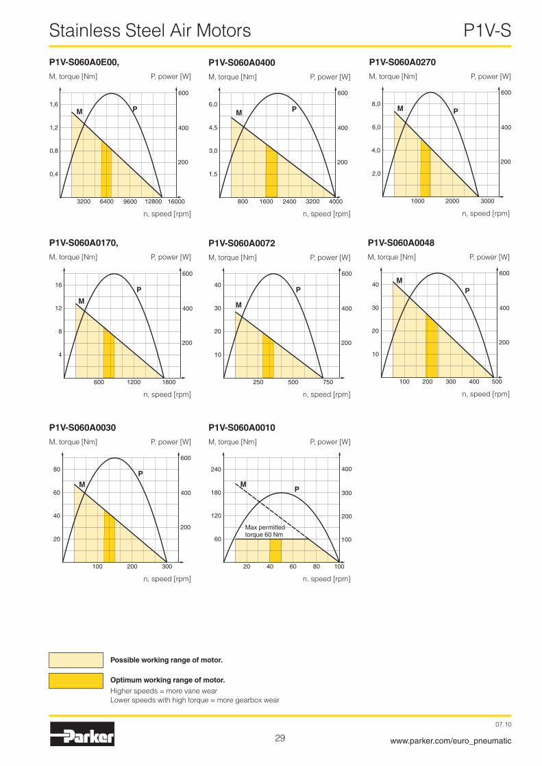
Max power Free Speed at Torque Min Air con- Conn. Min pipe Weight Order code speed max at max start sumption at ID power power torque max power kW rpm rpm Nm Nm l/s mm Kg
0,600 14000 7000 0,8� 1,�3 14,5 G3/8 1� �,000 P1V-S060A0E00
0,600 4000 �000 �,90 4,30 14,5 G3/8 1� �,100 P1V-S060A0400
0,600 �700 1350 4,�0 6,40 14,5 G3/8 1� �,100 P1V-S060A0270
0,600 1700 850 6,70 10,10 14,5 G3/8 1� �,100 P1V-S060A0170
0,600 7�0 360 15,90 �4,00 14,5 G3/8 1� �,�00 P1V-S060A0072
0,600 480 �40 �3,90 36,00 14,5 G3/8 1� �,�00 P1V-S060A0048
0,600 300 150 38,�0 57,00 14,5 G3/8 1� �,300 P1V-S060A0030
0,300 100 50 60,00* 60,00* 13,0 G3/8 1� �,300 P1V-S060A0010
* Max permitted torque
NOTE! All technical data is based on a working pressure of 6 bar.
Installation brackets, see page 35
Dimensions, see page 40
Permitted shaft loadings, see page 60
Service kits, see page 62
II2 GD c IIC T6 (80 °C) X
�9
Stainless Steel Air Motors P1V-S
07.10
www.parker.com/euro_pneumatic
P1V-S060A0270
M, torque [Nm] P, power [W]
P1V-S060A0170,
M, torque [Nm] P, power [W]
P1V-S060A0072
M, torque [Nm] P, power [W]
P1V-S060A0048
M, torque [Nm] P, power [W]
P1V-S060A0030
M, torque [Nm] P, power [W]
P1V-S060A0010
M, torque [Nm] P, power [W]
n, speed [rpm]
n, speed [rpm] n, speed [rpm]
n, speed [rpm] n, speed [rpm]
n, speed [rpm]
600
200
400
2,0
4,0
6,0
8,0M P
1000 2000 3000
600
200
400
4
8
12
16
M
P
600 1200 1800
600
200
400
10
20
30
40
M
P
250 500 750
600
200
400
10
20
30
40 MP
100 200 500300 400
600
200
400
20
40
60
80
MP
100 200 300
400
300
100
200
60
120
180
240
MP
20 40 60 80 100
P1V-S060A0E00,
M, torque [Nm] P, power [W]
P1V-S060A0400
M, torque [Nm] P, power [W]
n, speed [rpm] n, speed [rpm]
600
200
400
0,4
0,8
1,2
1,6M P
3200 6400 9600 12800 16000
600
200
400
1,5
3,0
4,5
6,0M P
800 1600 2400 3200 4000
Possible working range of motor.
Optimum working range of motor.
Higher speeds = more vane wearLower speeds with high torque = more gearbox wear
Max permitted torque 60 Nm

30
Stainless Steel Air Motors P1V-S
07.10
www.parker.com/euro_pneumatic
Data for reversible air motor with keyed shaft, P1V-S120A series
Max power Free Speed at Torque Min Air con- Conn. Min pipe Weight Order code speed max at max start sumption at ID power power torque max power kW rpm rpm Nm Nm l/s mm Kg
1,�00 8000 4000 �,90 4,30 �7 G3/4 19 5,5 P1V-S120A0800
1,�00 �700 1350 8,50 1�,70 �7 G3/4 19 5,5 P1V-S120A0270
1,�00 1100 550 �1,00 31,00 �7 G3/4 19 5,5 P1V-S120A0110
1,�00 780 390 �9,40 44,00 �7 G3/4 19 5,6 P1V-S120A0078
1,�00 3�0 160 71,60 107,00 �7 G3/4 19 5,6 P1V-S120A0032
0,700 �00 100 66,90 110,00* 19 G3/4 19 5,6 P1V-S120A0012
* Max permitted torque
Installation brackets, see page 35
Dimensions, see page 41
Permitted shaft loadings, see page 60
Service kits, see page 62
NOTE! All technical data is based on a working pressure of 6 bar.
II2 GD c IIC T5 (95 °C) X

31
Stainless Steel Air Motors P1V-S
07.10
www.parker.com/euro_pneumatic
P1V-S120A0800
M, torque [Nm] P, power [W]
P1V-S120A0270,
M, torque [Nm] P, power [W]
P1V-S120A0110
M, torque [Nm] P, power [W]
P1V-S120A0078
M, torque [Nm] P, power [W]
P1V-S120A0032
M, torque [Nm] P, power [W]
P1V-S120A0012
M, torque [Nm] P, power [W]
n, speed [rpm] n, speed [rpm]
n, speed [rpm] n, speed [rpm] n, speed [rpm]
n, speed [rpm]
1200
400
800
1,5
3,0
4,5
6,0
M P
2000 4000 6000 8000
1200
400
800
4
8
12
16M
P
1000 2000 3000
1200
400
800
10
20
30
40M
P
400 800 1200
1200
400
800
15
30
45
60M
P
250 500 750
1200
400
800
50
100
150
M P
100 200 300
800
200
400
600
100
150
50
200
MP
40 80 160 200120
Max permitted torque 110 Nm
Possible working range of motor.
Optimum working range of motor.
Higher speeds = more vane wearLower speeds with high torque = more gearbox wear

3�
Stainless Steel Brake Motors P1V-S
07.10
www.parker.com/euro_pneumatic
Brake motor
Brake motorsApplicationsThe integrated brake is a spring-loaded disk brake, which is released at a minimum air pressure of 5 bar. The brake is applied in the absence of pressure. As soon as the control port for the brake is placed under pressure, the piston (1) is pressurised and the spring (�) is compressed. The motor can now start and the torque is passed to the shaft (3). The ventilation air from the brake is connected with the atmosphere. In order to brake the motor, the control air to the brake is simply vented. The piston (1) is pushed to the right by the spring (�), and the axle (3) is jammed between the two brake disks (4).
The technology and the size of air motors with integrated running and stationary brake make them ideal applications requiring repeated precise positioning. The motor can also be kept stationary in a specific position, and the stopping time for a rotating weight can be shortened significantly. Another typical application for brake motors is when the output shaft needs to be held in one position when the motor stops delivering torque. The brake can handle more than 1500 braking operations per hour at maximum braking torque.
Disassembly and reassemblyDetach the connections with the motor and gearbox. Pull off the motor and gearbox part. The brake disks can be lifted off after the lock ring has been removed.
Service and maintenanceAfter �0 000 braking operations as a stationary brake or 10 000 braking operations as an operating brake, the brake must be disassembled in order to check for wear.
Warning:If the number of braking operations is exceeded, the degree of wear might be greater than permitted and the braking effect might be lost. If this happens, you simply need to replace the worn brake linings. Tests show that the brake lining needs to be replaced after approx. 90 000 braking cycles
Technical data Min braking torque for different motor typesMotor size P1V-S0�0, �00 watt
Braking Motor Brake Gearbox motor max min braking max torque, torque, torque, specified theoretical permitted Nm Nm Nm
P1V-S0�0A/DDE50 0,5� 1,0 1,0P1V-S0�0A/DD460 1,6 3,43 3,43P1V-S0�0A/DD�40 3,� 6,66 6,66P1V-S0�0A/DD140 5,4 11,8 11,8P1V-S0�0A/DD070 10,8 ��,86 14,0P1V-S0�0A/DD035 �0,0 44,4 �0,0P1V-S0�0A/DD018 �0,0 44,4 �0,0P1V-S0�0A/D011 66,0 137,� 108,0P1V-S0�0A/D006 144,0 �66,4 108,0P1V-S0�0A/DD005 �0,0* 44,4 �0,0P1V-S0�0A/D00� �0,0* 44,4 �0,0P1V-S0�0A/D001 �0,0* 44,4 �0,0P1V-S0�0A/D0005 �0,0* 44,4 �0,0
Motor size P1V-S030, 300 watt
Braking Motor Brake Gearbox motor max min braking max torque, torque, torque, specified theoretical permitted Nm Nm Nm
P1V-S030A/DDE50 0,8 1,0 1,0P1V-S030A/DD460 �,4 3,43 3,43P1V-S030A/DD�40 4,8 6,66 6,66P1V-S030A/DD140 8,� 11,8 11,8P1V-S030A/DD060 19,� �0,6 14,0P1V-S030A/DD0�8 41,0 40,0 36,0P1V-S030A/D0�3 48,0 70,8 108,0P1V-S030A/D010 114,0 1�3,6 108,0P1V-S030A/DD005 36,0* 40,0 36,0
* Warning:The permitted torque for the specific gearbox must not be exceeded!
Brake releaseMinimum pressure for brake release: 5 bar
1. Piston
Vent for motor brake Control port for motor brake
3. Shaft
�. Compression spring 4. Brake disks
NOTE! Brake motors must only ever be supplied with unlubricated air, otherwise there is a risk of oil from the supply air getting into the brake unit, resulting in poor brake performance or no braking effect.

33
Stainless Steel Brake Motors P1V-S
07.10
www.parker.com/euro_pneumatic
Data for reversible brake motor with keyed shaft, P1V-S020AD series
Max power Free Speed at Torque Min Air con- Conn. Min pipe Weight Order code speed max at max start sumption at ID power power torque max power kW rpm rpm Nm Nm l/s mm Kg
0,�00 14500 7�50 0,�6 0,40 6,3 G1/8 10 1,000 P1V-S020ADE50
0,�00 4600 �300 0,80 1,�0 6,3 G1/8 10 1,050 P1V-S020AD460
0,�00 �400 1�00 1,60 �,40 6,3 G1/8 10 1,050 P1V-S020AD240
0,�00 1400 700 �,70 4,10 6,3 G1/8 10 1,150 P1V-S020AD140
0,�00 700 350 5,40 8,�0 6,3 G1/8 10 1,150 P1V-S020AD070
0,�00 350 160 1�,00 18,00 6,3 G1/8 10 1,150 P1V-S020AD035
0,100 180 90 10,50 15,00 4,5 G1/8 10 1,150 P1V-S020AD018
0,�00 110 55 33,00 49,50 6,3 G1/8 10 3,300 P1V-S020AD011
0,�00 60 30 7�,00 108,00* 6,3 G1/8 10 3,300 P1V-S020AD006
0,180 50 �5 �0,00* �0,00* 6,3 G1/8 10 1,�50 P1V-S020AD005
0,180 �0 – �0,00* �0,00* 6,3 G1/8 10 1,�50 P1V-S020AD002
0,180 10 – �0,00* �0,00* 6,3 G1/8 10 1,350 P1V-S020AD001
0,180 5 – �0,00* �0,00* 6,3 G1/8 10 1,350 P1V-S020AD0005
* Max permitted torque
NOTE! All technical data is based on a working pressure of 6 bar.
Torque curves, see page 24
Installation brackets, see page 35
Dimensions, see page 42
Permitted shaft loadings, see page 60
Service kits, see page 62
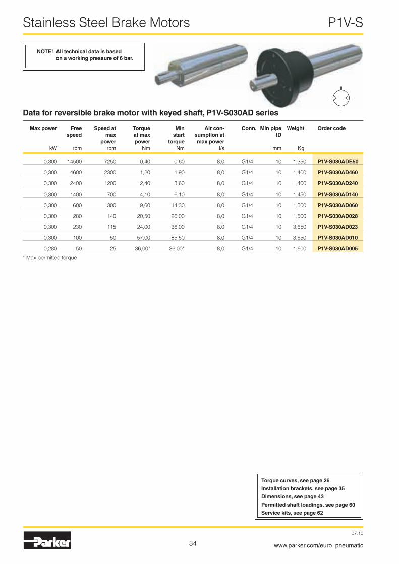
34
Stainless Steel Brake Motors P1V-S
07.10
www.parker.com/euro_pneumatic
Data for reversible brake motor with keyed shaft, P1V-S030AD series
Max power Free Speed at Torque Min Air con- Conn. Min pipe Weight Order code speed max at max start sumption at ID power power torque max power kW rpm rpm Nm Nm l/s mm Kg
0,300 14500 7�50 0,40 0,60 8,0 G1/4 10 1,350 P1V-S030ADE50
0,300 4600 �300 1,�0 1,90 8,0 G1/4 10 1,400 P1V-S030AD460
0,300 �400 1�00 �,40 3,60 8,0 G1/4 10 1,400 P1V-S030AD240
0,300 1400 700 4,10 6,10 8,0 G1/4 10 1,450 P1V-S030AD140
0,300 600 300 9,60 14,30 8,0 G1/4 10 1,500 P1V-S030AD060
0,300 �80 140 �0,50 �6,00 8,0 G1/4 10 1,500 P1V-S030AD028
0,300 �30 115 �4,00 36,00 8,0 G1/4 10 3,650 P1V-S030AD023
0,300 100 50 57,00 85,50 8,0 G1/4 10 3,650 P1V-S030AD010
0,�80 50 �5 36,00* 36,00* 8,0 G1/4 10 1,600 P1V-S030AD005
* Max permitted torque
NOTE! All technical data is based on a working pressure of 6 bar.
Torque curves, see page 26
Installation brackets, see page 35
Dimensions, see page 43
Permitted shaft loadings, see page 60
Service kits, see page 62
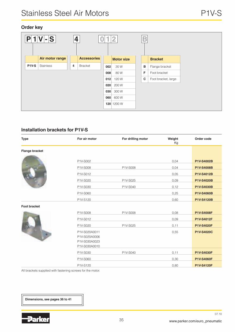
35
Stainless Steel Air Motors P1V-S
07.10
www.parker.com/euro_pneumatic
Installation brackets for P1V-S
Type For air motor For drilling motor Weight Order code Kg
Flange bracket
P1V-S00� 0,04 P1V-S4002B
P1V-S008 P1V-S008 0,04 P1V-S4008B
P1V-S01� 0,05 P1V-S4012B
P1V-S0�0 P1V-S0�5 0,09 P1V-S4020B
P1V-S030 P1V-S040 0,1� P1V-S4030B
P1V-S060 0,�5 P1V-S4060B
P1V-S1�0 0,60 P1V-S4120B
Foot bracket
P1V-S008 P1V-S008 0,08 P1V-S4008F
P1V-S01� 0,09 P1V-S4012F
P1V-S0�0 P1V-S0�5 0,11 P1V-S4020F
P1V-S0�0A0011 0,55 P1V-S4020C P1V-S0�0A0006 P1V-S030A00�3 P1V-S030A0010
P1V-S030 P1V-S040 0,11 P1V-S4030F
P1V-S060 0,30 P1V-S4060F
P1V-S1�0 0,80 P1V-S4120F
All brackets supplied with fastening screws for the motor.
P 1 V - S 4 0 1 2 B
Order key
Accessories
4 Bracket
Air motor range
P1V-S Stainless
Motor size
002 �0 W
008 80 W
012 1�0 W
020 �00 W
030 300 W
060 600 W
120 1�00 W
Bracket
B Flange bracket
F Foot bracket
C Foot bracket, large
Dimensions, see pages 36 to 41

36
Stainless Steel Air Motors P1V-S
07.10
www.parker.com/euro_pneumatic
Dimensions
Motor P1V-S002
Dimensions
Motor P1V-S008
Flange bracket for motor P1V-S008P1V-S4008B
Foot bracket for motor P1V-S008P1V-S4008F
Flange bracket for motor P1V-S002P1V-S400�B
Ø20
e8
Ø6
2
5,5
1,5
Ø32
Ø8
H7
26
3,2
Ø40
5
Ø4,
5
Ø13
H8
Ø30
4 x
90°
5
4225
-0,
2
Ø13
H8
2030
Ø5,5
4
4050
25
M8 x 0,75
M8 x 0,75 M8 x 0,75
L R
13
12
2
50
100
123,5
6
2
7,5
Ø22
d9
SW20
M3
13 e8
Ø6 k6
Ø15
5 -0
,1
Clamping area
Inlet anticlockwise
Inlet clockwise
Outlet
132,5
13,5
10
70,5
35Ø8
e8
Ø4
k6
1 -0,1
Ø17
e8
Ø17
-0,
1
17 -0,1M2,5 x 5
27,5 Ø12
120°
3,5
-0,1
M5 Inlet anticlockwise
M5 Inlet clockwise
Clamping area
Outlet
CAD drawings on the InternetOur home page www.parker.com/euro_pneumatic includes the AirCad Drawing Library with �D and 3D drawings for the main versions.

37
Stainless Steel Air Motors P1V-S
07.10
www.parker.com/euro_pneumatic
Dimensions
Motor P1V-S012
A B
P1V-S01�A0N00, P1V-S01�D0N00 117,0 46,5P1V-S01�A0550, P1V-S01�D0550 117,0 46,5P1V-S01�A0360, P1V-S01�D0360 117,0 46,5P1V-S01�A0140, P1V-S01�D0140 1�9,5 59,0P1V-S01�A0090, P1V-S01�D0090 1�9,5 59,0P1V-S01�A0060, P1V-S01�D0060 1�9,5 59,0P1V-S01�A0010, P1V-S01�D0010 14�,0 71,5
Ø4,5
Ø40
Ø13
H8
5
Ø50
40
50
Ø13
H84,5
42
-0,2
25
Ø5,5
4,5
20
30
Flange bracket for motor P1V-S012P1V-S401�B
Foot bracket for motor P1V-S012P1V-S401�F
M4x4,5
Ø21L R
6,8 6,8
47,
9
G1/8 G1/81//
G1/8/
Ø13
e8
SW
24
Ø27
e8
Ø27
d977
24
8
A
0,84
17 B
A2x2x14 DIN 6885
Ø8
k65/
16"-
24 U
NF
9,519,5 Ø
12,5
11
18
OutletStainless key Clamping area
InletInletP1V-S012Awith shaft with keyed shaft
P1V-S012Dwith threaded shaft
CAD drawings on the InternetOur home page www.parker.com/euro_pneumatic includes the AirCad Drawing Library with �D and 3D drawings for the main versions.

38
Stainless Steel Air Motors P1V-S
07.10
www.parker.com/euro_pneumatic
5,8
5
20e8
20H
8
5,5
50
60
20H
8
4,5
-0,2
30 6,6 4,5
3020
5545
47
Motor P1V-S020
A B
P1V-S0�0A0E50, P1V-S0�0D0E50 1�7 63,5P1V-S0�0A0460, P1V-S0�0D0460 1�7 63,5P1V-S0�0A0�40, P1V-S0�0D0�40 1�7 63,5P1V-S0�0A0140, P1V-S0�0D0140 143 79,5P1V-S0�0A0070, P1V-S0�0D0070 143 79,5P1V-S0�0A0035, P1V-S0�0D0035 143 79,5P1V-S0�0A0018, P1V-S0�0D0018 143 79,5P1V-S0�0A0005, P1V-S0�0D0005 159 95,5P1V-S0�0A000� 159 95,5P1V-S0�0A0001 175 111,5P1V-S0�0A00005 175 111,5
Flange bracket for motor P1V-S020P1V-S40�0B
Foot bracket for motor P1V-S020P1V-S40�0F
19
7
8
G1/8 G1/8
G1/4
M4x4
Ø30Ø20
e8
SW
34
Ø38
e8
Ø38
d9
34
8
A
0,885
B
A3x3x18 DIN 6885
23
Ø10
k63/
8"-2
4 U
NF
26
Ø16
,5
15
14
24
Clamping area
InletInlet
Outlet
Stainless key
P1V-S020Awith shaft with keyed shaft
P1V-S020Dwith threaded shaft
8535,550,5
Ø11
(9,5)
(9,5
)
Ø74
110
70
120
5x45
°
Foot bracket for motor P1V-S020A0011 and P1V-S020A0006P1V-S40�0C
209,5
148
143
34
34
Ø38
d9
249,56 P
9
40
39
28
Ø19
k6
Ø99
Ø74
M8 x 20
15
M6
21,5
Ø85
P1V-S020A0011P1V-S020A0006
Oil plugBlack oxidised steel
CAD drawings on the InternetOur home page www.parker.com/euro_pneumatic includes the AirCad Drawing Library with �D and 3D drawings for the main versions.

39
Stainless Steel Air Motors P1V-S
07.10
www.parker.com/euro_pneumatic
20
6,5
11
G1/4 G1/4
G1/4
36
L R Ø24
e8
SW
36
Ø42
d9
A B
0,85
C
F
D
ØE
k6
10
Ø42
d9
M5x
5,5
Ø34
Ø16
,5
27
15
3/8"
-24
UN
F
14
5,5
55
6,8
6
24e8
24H
8
2165
6050
24H
8
4,5
-0,2
30 6,6 4,5
3020
48
Inlet Inlet
Outlet
Stainless keyClamping area
Motor P1V-S030
A B C D E F
P1V-S030A0E50, P1V-S030D0E50 �8,5 143 66 �7 1� A4x4x�0 DIN 6885P1V-S030A0460, P1V-S030D0460 �8,5 143 66 �7 1� A4x4x�0 DIN 6885P1V-S030A0�40, P1V-S030D0�40 �8,5 143 66 �7 1� A4x4x�0 DIN 6885P1V-S030A0140, P1V-S030D0140 �8,5 159 8� �7 1� A4x4x�0 DIN 6885P1V-S030A0060, P1V-S030D0060 3�,0 159 8� 30 14 A5x5x�0 DIN 6885P1V-S030A00�8, P1V-S030D00�8 3�,0 159 8� 30 14 A5x5x�0 DIN 6885P1V-S030A0018, P1V-S030D0018 3�,0 159 8� 30 14 A5x5x�0 DIN 6885P1V-S030A0005, P1V-S030D0005 3�,0 164 8� 30 14 A5x5x�0 DIN 6885
Flange bracket for motor P1V-S030P1V-S4030B
Foot bracket for motor P1V-S030P1V-S4030F
P1V-S030Awith shaft with keyed shaft
P1V-S030Dwith threaded shaft
225,5
159
82
Ø42
d9
M6
21,5
Ø85
M8x20
40
39
28
265,5
6 p9
36
Ø19
k6 34
15
5
Ø99
Ø74
8535,550,5
Ø11
(9,5)
(9,5
)
Ø74
110
70
120
5x45
°
Foot bracket for motorP1V-S030A00�3 and P1V-S030A0010P1V-S40�0C
Black oxidised steelOil plug
P1V-S030A0023P1V-S030A0010
CAD drawings on the InternetOur home page www.parker.com/euro_pneumatic includes the AirCad Drawing Library with �D and 3D drawings for the main versions.

40
Stainless Steel Air Motors P1V-S
07.10
www.parker.com/euro_pneumatic
14
G3/8 G3/8
G1/2
11,5
50
35e8
SW
50
56d1
0
A
B
8
C
F
Ek6
10
56e8
1
D
48
M6x7
24
Ø70
Ø6,6
8,5
1,5 Ø35
H8
7,5
Ø32
Ø35
Ø85
e8-1
0,5 x 45
Inlet Inlet
Outlet
Stainless keyClamping area
Motor P1V-S060
A B C D E F
P1V-S060A0E00 194 16� 6�,4 30 14 A5x5x�0 DIN 6885P1V-S060A0400 194 16� 6�,4 30 14 A5x5x�0 DIN 6885P1V-S060A0�70 194 16� 6�,4 30 14 A5x5x�0 DIN 6885P1V-S060A0170 194 16� 6�,4 30 14 A5x5x�0 DIN 6885P1V-S060A007� �1� 180 6�,4 30 14 A5x5x�0 DIN 6885P1V-S060A0048 �1� 180 80,4 30 19 A6x6x�� DIN 6885P1V-S060A0030 �17 180 80,4 35 19 A6x6x�� DIN 6885P1V-S060A0010 �17 180 80,4 35 19 A6x6x�� DIN 6885
Flange bracket for motor P1V-S060P1V-S4060B
Foot bracket for motor P1V-S060P1V-S4060F
85
70
50
Ø35
H8
5,5
-0,2
40
6,6
5,5
50 -1
25
70 62
-1
CAD drawings on the InternetOur home page www.parker.com/euro_pneumatic includes the AirCad Drawing Library with �D and 3D drawings for the main versions.

41
Stainless Steel Air Motors P1V-S
07.10
www.parker.com/euro_pneumatic
11,5
Ø50
H8
10
Ø46
Ø50
e8 -1
Ø100
Ø9
Ø11
5
110
92
62
Ø50
H8
9,5
Ø11 9,5
50
35
-1
99,5
1+
-0,2
60
50e8
SW
70
82d1
0
234,5
197
1065
A6x6x22 DIN 688519
k6
10
82e9
35
22
G3/4
12,5
SW70
G 1/239
68
M8x14
50e8
SW
70
82d1
0
267,5
205
1073
A8x7x50 DIN 6885
28k6
10
82e9
60
68
M8x14
20
M10
1,5
Motor P1V-S120
P1V-S120A0800P1V-S120A0270P1V-S120A0110
P1V-S120A0078P1V-S120A0032P1V-S120A0012
Flange bracket for motor P1V-S120P1V-S41�0B
Inlet Inlet
Outlet
Stainless key
Clamping area
Clamping areaStainless key
Foot bracket for motor P1V-S120P1V-S41�0F
CAD drawings on the InternetOur home page www.parker.com/euro_pneumatic includes the AirCad Drawing Library with �D and 3D drawings for the main versions.

4�
Stainless Steel Brake Motors P1V-S
07.10
www.parker.com/euro_pneumatic
5,8
5
20e8
20H
8
5,5
50
60
20H
8
4,5
-0,2
30 6,6 4,5
3020
5545
47
A B
P1V-S0�0ADE50 170 63,5P1V-S0�0AD460 170 63,5P1V-S0�0AD�40 170 63,5P1V-S0�0AD140 186 79,5P1V-S0�0AD070 186 79,5P1V-S0�0AD035 186 79,5P1V-S0�0AD018 186 79,5P1V-S0�0AD005 �0� 95,5P1V-S0�0AD00� �0� 95,5P1V-S0�0AD001 �18 111,5P1V-S0�0AD0005 �18 111,5
Flange bracket for motor P1V-S020P1V-S40�0B
Foot bracket for motor P1V-S020P1V-S40�0F
19
7
8
G1/81/1/G1/8
G1/4//
M4x4
3020e8
SW
34
38e8
38d9
34
8
24 A
0,85
B
A3x3x18 DIN 6885
23
10k6
M5
Clamping area
InletInlet
Outlet
Stainless key
P1V-S020ADwith shaft with keyed shaft
P1V-S020DDwith threaded shaft
8535,550,5
Ø11
(9,5)
(9,5
)
Ø74
110
70
120
5x45
°
Foot bracket for motor P1V-S020AD0011 and P1V-S020AD0006P1V-S40�0C
252,5
119
186
34
34
Ø38
d9
292,56 P
9
40
39
28
Ø19
k6
Ø99
Ø74
M8 x 20
15
M6
21,5
Ø85
M5
P1V-S020AD011P1V-S020AD006
Black oxidised steelOil plug
Brake connection
Brake motor P1V-S020
Brake connection
CAD drawings on the InternetOur home page www.parker.com/euro_pneumatic includes the AirCad Drawing Library with �D and 3D drawings for the main versions.

43
Stainless Steel Brake Motors P1V-S
07.10
www.parker.com/euro_pneumatic
20
6,5
11
G1/4 G1/4
G1/4
36
L R Ø24
e8
SW
36
Ø42
d9
A B
0,85
C
F
D
ØE
k6
10
Ø42
d9
M5x
5,5
Ø34M5
5,5
55
6,8
6
24e8
24H
8
2165
6050
24H
8
4,5
-0,2
30 6,6 4,5
3020
48
Inlet Inlet
Outlet
Stainless keyClamping area
Brake motor P1V-S030
A B C D E F
P1V-S030ADE50 �8,5 186 66 �7 1� A4x4x�0 DIN 6885P1V-S030AD460 �8,5 186 66 �7 1� A4x4x�0 DIN 6885P1V-S030AD�40 �8,5 186 66 �7 1� A4x4x�0 DIN 6885P1V-S030AD140 �8,5 �0� 8� �7 1� A4x4x�0 DIN 6885P1V-S030AD060 3�,0 �0� 8� 30 14 A5x5x�0 DIN 6885P1V-S030AD0�8 3�,0 �0� 8� 30 14 A5x5x�0 DIN 6885P1V-S030AD005 3�,0 �07 8� 30 14 A5x5x�0 DIN 6885
Flange bracket for motor P1V-S030P1V-S4030B
Foot bracket for motor P1V-S030P1V-S4030F
P1V-S030Awith shaft with keyed shaft
P1V-S030Dwith threaded shaft
268,5
202
82
Ø42
d9
M6
21,5
Ø85
M8x20
40
39
28
308,5
6 p9
36
Ø19
k6 34
15
5
Ø99
Ø74
M5
8535,550,5
Ø11
(9,5)
(9,5
)
Ø74
110
70
120
5x45
°
Foot bracket for motor P1V-S030AD0023 and P1V-S030AD0010P1V-S40�0C
Black oxidised steelOil plug
P1V-S030AD023P1V-S030AD010
Brake connection
Brake connection
CAD drawings on the InternetOur home page www.parker.com/euro_pneumatic includes the AirCad Drawing Library with �D and 3D drawings for the main versions.

44
Drilling, milling and grinding motors P1V-S
07.10
www.parker.com/euro_pneumatic
Drilling, milling and grinding motorsA large number of drilling motors, milling motors and grinding motors have been developed using the P1V-S as the base motor in order to make it easier to install air motors in machining applications. These motors are all equipped with standard vanes for intermittent lubrication-free operation, although it is recommended to use oil mist if you are planning to operate them for extended periods.
NOTE! These motors are not made of 100% stainless steel.
Drilling motors are available with power ratings of 80, 170, �50 and 400 Watts, and several different speeds for the machining of a range of materials. They can be fitted with collet chucks, drill chucks and quick-release chucks. Many of them also have accessories allowing the exhaust air to be removed.
The milling motor, with a power rating of 400 Watts, runs at a relatively high speed, and is fitted with a collet chuck for a shaft diameter of 8 mm. It is equipped with strong bearings able to handle greater shear forces on the spindle.
The grinding motor, with a power rating of �00 Watts, is fitted with a collet chuck for a shaft diameter of 8 mm and runs at a relatively high speed. It is equipped with strong bearings able to handle greater shear forces on the spindle.
The design principle of the 90 Watt grinding motor is different from the others. The turbine principle means that high speeds are possible without the need for lubrication.
Feed movement in drilling, milling and grinding motorsA slow and even feed movement is necessary in machining applications. During drilling, the feed must not uncontrollably speed up once the drill breaks through the material. One good way of solving the problem is to use a pneumatic cylinder for the feed, which is able to provide force during drilling and a rapid approach before the actual drilling phase. Feed during the drilling phase is controlled using a hydraulic brake cylinder (HYDROCHECK) fitted in parallel with the pneumatic cylinder. This provides even, slow and safe feed movement, without the risk of the uncontrolled feed described above.
Technical data:Working pressure: Max 7 barWorking temperature: -30 °C to +100 °CMedium: 40 µm filtered oil mist (unlubricated for grinding motor P1V-S009)
Other technical dataSee table for each motor
Material specificationDrilling motors P1V-S008N, P1V-S0�5N/M, P1V-S040M, milling motor P1V-S040N and grinding motor P1V-S0�0NHousing Stainless steel, X1�Cr13Shaft, collet chuck Hardened steel (not stainless)Shaft for drill chuck Hardened and tempered steel (not stainless)
Drilling motors P1V-S017N/M and grinding motor P1V-S009NHousing High grade steel (not stainless)Shaft, collet chuck Hardened steel (not stainless)Shaft for drill chuck Hardened and tempered steel (not stainless)
AllInternal parts High grade steel (not stainless)
Accessories Surface treated steel, plastic aluminium
P 1 V - S 0 1 7 N 0 Q 0 0
Order key
Possible combinationsPlease refer to pages 45 to 5�.
Function
M B10/B1� shaft
N Collet chuck
Motor size
008 80 W
009 90 W
017 170 W
025 �50 W
030 300 W
040 400 W
Free speed per min
035 350 999 9990
A00 10000 H00 17000 L00 �0000 Q00 �4000 X00 30000 A000 100000
Air motor range
P1V-S Drilling, milling and grinding motors

45
Drilling, milling and grinding motors P1V-S
07.10
www.parker.com/euro_pneumatic
Drilling motor P1V-S008NOur smallest and most versatile drilling motor for small-scale drilling operations.The standard collet chuck is for 3 mm shaft diameter. For other diameters, select a different collet chuck as an accessory. The motor has a port for a 6 mm hose to remove the exhaust air to a silencer.
Data for drilling motor P1V-S008N
Max power Free Version Drilling in Drilling in Air con- Conn. Min pipe Weight Order code speed steel aluminium sumption at ID max power kW rpm mm mm l/s mm Kg
0,080 �4000 Collet chuck 3 mm - 3 3,8 M8 x 0,75* 4 0,�0 P1V-S008N0Q00
0,080 7000 Collet chuck 3 mm 3 3 3,8 M8 x 0,75* 4 0,�0 P1V-S008N0700
0,080 1900 Collet chuck 3 mm 3 3 3,8 M8 x 0,75* 4 0,�� P1V-S008N0190
0,080 1300 Collet chuck 3 mm 3 3 3,8 M8 x 0,75* 4 0,�� P1V-S008N0130
* � push in nipples (F�8PMB6M8SP) for plastic pipe Ø6/4 supplied
Accessories for drilling motor P1V-S008N
Name Order code
Collet chucks
Collet chuck � mm P1V-6/314693
Collet chuck Ø3 mm Standard
Collet chuck Ø3/3�" P1V-6/314694
Collet chuck Ø1/8" P1V-6/314407
Average speed Drilling Ømm Material 1 2 3 4 5 6 7 8 9 10
35 m/min 11000 5500 3700 �800 ��00 1900 1600 1400 1�00 1100 Unalloyed steel up to 500 N/mm²�8 m/min 8800 4400 3000 ��00 1800 1500 1300 1100 975 880 Unalloyed steel from 500 to 700 N/mm²�5 m/min 7800 3900 �600 �000 1600 1300 1100 975 865 780 Unalloyed steel over 700 N/mm²14 m/min 4400 ��00 1500 1100 880 735 630 550 490 440 Alloyed steel from 700 to 900 N/mm²11 m/min 3400 1700 1100 850 680 570 485 4�5 380 340 Alloyed steel from 900 to 1100 N/mm² 7 m/min ��00 1100 730 550 440 365 315 �75 �45 ��0 Stainless steel�� m/min 7000 3500 �300 1700 1400 1�00 1000 875 780 700 Cast iron up to 180 N/mm²1� m/min 3800 1900 1300 950 760 630 540 475 4�0 380 Cast iron over 180 N/mm² 50 m/min 16000 8000 5300 4000 3�00 �700 �300 �000 1800 1600 Copper, red metal, bronze, brass 90 m/min �8000 14000 9000 7000 5600 4800 4000 3500 3100 �800 Rough light-alloy metal, screw brass²165 m/min 5�000 �6000 17300 13000 10400 8700 7400 6500 5800 5�00 Hardened light-alloy metal�10 m/min 66000 33000 ��000 16500 13�00 11000 9400 8300 7400 6600 Magnesium alloy¹
NOTE! All technical data is based on a working pressure of 6 bar.
Installation brackets, see page 35Dimensions, see page 53Permitted shaft loadings, see page 61Service kits, see page 64
Standard speeds for HSS spiral drills
1 Speeds for processing two-component plastics, cardboard or plastic-coated fabrics plaster, HSS drills must not be used - use a high-speed steel drill fitted with a hard metal K10 instead
� double the values for thermoplastics

46
Drilling, milling and grinding motors P1V-S
07.10
www.parker.com/euro_pneumatic
Drilling motor P1V-S017NA small drilling motor for small-scale, lighter drilling operations. The standard collet chuck is for 6 mm shaft diameter. For other diameters, select a different collet chuck as an accessory.The motor has a built-in silencer for exhaust air. If lower noise levels are required, or if you want the exhaust air to be collected, the relevant accessories are available.
Data for drilling motor P1V-S017N
Max power Free Version Drilling in Drilling in Air con- Conn. Min pipe Weight Order code speed steel aluminium sumption at ID max power kW rpm mm mm l/s mm Kg
0,170 �4000 Collet chuck 6 mm - 4 5,0 G1/4o 6 0,38 P1V-S017N0Q00
0,170 6000 Collet chuck 6 mm 3 5 5,0 G1/4o 6 0,38 P1V-S017N0600
0,170 4000 Collet chuck 6 mm 4 6 5,0 G1/4o 6 0,38 P1V-S017N0400
0,170 1500 Collet chuck 6 mm 4 6 5,0 G1/4o 6 0,38 P1V-S017N0150
0,170 1000 Collet chuck 6 mm 4 6 5,0 G1/4o 6 0,38 P1V-S017N0100
0,170 660 Collet chuck 6 mm 4 6 5,0 G1/4o 6 0,38 P1V-S017N0066
Accessories for drilling motor P1V-S017N
Name Order code
Collet chucks
Collet chuck Ø3 mm P1V-6/312681
Collet chuck Ø4 mm P1V-6/312684
Collet chuck Ø5 mm P1V-6/312686
Collet chuck Ø6 mm Standard
Collet chuck Ø1/8" P1V-6/312682
Collet chuck Ø1/4" P1V-6/312689
Other accessories Outlet hose P1V-6/806112
Seal for outlet hose P1V-6/823221
Outlet connection parallel P1V-6/302923A
NOTE! All technical data is based on a working pressure of 6 bar.
Dimensions, see page 53
Permitted shaft loadings, see page 61
Service kits, see page 64
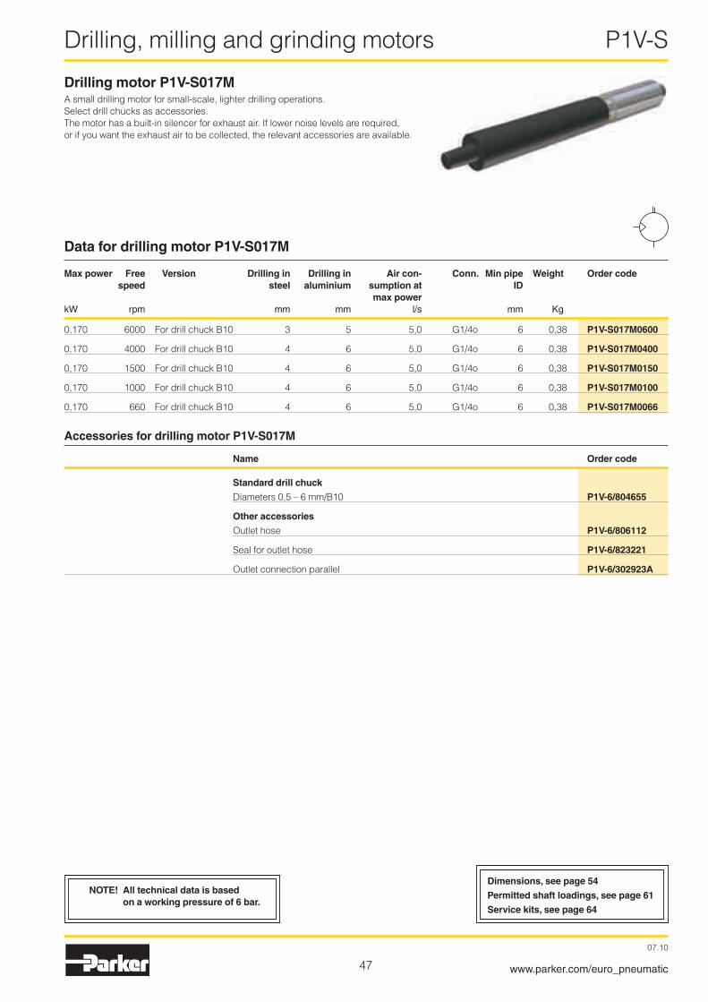
47
Drilling, milling and grinding motors P1V-S
07.10
www.parker.com/euro_pneumatic
Drilling motor P1V-S017MA small drilling motor for small-scale, lighter drilling operations. Select drill chucks as accessories.The motor has a built-in silencer for exhaust air. If lower noise levels are required, or if you want the exhaust air to be collected, the relevant accessories are available.
Data for drilling motor P1V-S017M
Max power Free Version Drilling in Drilling in Air con- Conn. Min pipe Weight Order code speed steel aluminium sumption at ID max power kW rpm mm mm l/s mm Kg
0,170 6000 For drill chuck B10 3 5 5,0 G1/4o 6 0,38 P1V-S017M0600
0,170 4000 For drill chuck B10 4 6 5,0 G1/4o 6 0,38 P1V-S017M0400
0,170 1500 For drill chuck B10 4 6 5,0 G1/4o 6 0,38 P1V-S017M0150
0,170 1000 For drill chuck B10 4 6 5,0 G1/4o 6 0,38 P1V-S017M0100
0,170 660 For drill chuck B10 4 6 5,0 G1/4o 6 0,38 P1V-S017M0066
Accessories for drilling motor P1V-S017M
Name Order code
Standard drill chuck Diameters 0,5 – 6 mm/B10 P1V-6/804655
Other accessories Outlet hose P1V-6/806112
Seal for outlet hose P1V-6/823221
Outlet connection parallel P1V-6/302923A
NOTE! All technical data is based on a working pressure of 6 bar.
Dimensions, see page 54
Permitted shaft loadings, see page 61
Service kits, see page 64

48
Drilling, milling and grinding motors P1V-S
07.10
www.parker.com/euro_pneumatic
NOTE! All technical data is based on a working pressure of 6 bar.
Drilling motor P1V-S025NA small drilling motor for moderately heavy drilling operations. The standard collet chuck is for 6 mm shaft diameter. For other diameters, select a different collet chuck as an accessory.The motor has a built-in silencer for exhaust air. If lower noise levels are required, or if you want the exhaust air to be collected, the relevant accessories are available.
Data for drilling motor P1V-S025N
Max power Free Version Drilling in Drilling in Air con- Conn. Min pipe Weight Order code speed steel aluminium sumption at ID max power kW rpm mm mm l/s mm Kg
0,�50 17000 Collet chuck 6 mm - 6 6,3 G1/4o 6 0,80 P1V-S025N0H00
0,�50 4800 Collet chuck 6 mm 4 6 6,3 G1/4o 6 0,80 P1V-S025N0480
0,�50 �500 Collet chuck 6 mm 6 6 6,3 G1/4o 6 0,80 P1V-S025N0250
0,�50 1400 Collet chuck 6 mm 6 6 6,3 G1/4o 6 0,80 P1V-S025N0140
0,�50 700 Collet chuck 6 mm 6 - 6,3 G1/4o 6 0,80 P1V-S025N0070
0,�50 350 Collet chuck 6 mm 6 - 6,3 G1/4o 6 0,80 P1V-S025N0035
Accessories for drilling motor P1V-S025N
Name Order code
Collet chucks
Collet chuck Ø3 mm P1V-6/312681
Collet chuck Ø4 mm P1V-6/312684
Collet chuck Ø5 mm P1V-6/312686
Collet chuck Ø6 mm Standard
Collet chuck Ø1/8" P1V-6/312682
Collet chuck Ø1/4" P1V-6/312689
Other accessories Outlet connection straight P1V-6/313179A
Outlet hose �3 x �8 mm 0,75 m long P1V-6/806110
Outlet connection parallel P1V-6/388378A
Installation brackets, see page 35
Dimensions, see page 55
Permitted shaft loadings, see page 61
Service kits, see page 64

49
Drilling, milling and grinding motors P1V-S
07.10
www.parker.com/euro_pneumatic
NOTE! All technical data is based on a working pressure of 6 bar.
Drilling motor P1V-S025MA small drilling motor for moderately heavy drilling operations. Select drill chucks or quick-release chucks as accessories as necessary.The motor has a built-in silencer for exhaust air. If lower noise levels are required, or if you want the exhaust air to be collected, the relevant accessories are available.
Data for drilling motor P1V-S025M
Max power Free Version Drilling in Drilling in Air con- Conn. Min pipe Weight Order code speed steel aluminium sumption at ID max power kW rpm mm mm l/s mm Kg
0,�50 17000 For drill chuck B1� - 6 6,3 G1/4o 6 0,80 P1V-S025M0H00
0,�50 4800 For drill chuck B1� 4 6 6,3 G1/4o 6 0,80 P1V-S025M0480
0,�50 �500 For drill chuck B1� 6 8 6,3 G1/4o 6 0,80 P1V-S025M0250
0,�50 1400 For drill chuck B1� 8 10 6,3 G1/4o 6 0,80 P1V-S025M0140
0,�50 700 For drill chuck B1� 10 - 6,3 G1/4o 6 0,80 P1V-S025M0070
0,�50 350 For drill chuck B1� 10 - 6,3 G1/4o 6 0,80 P1V-S025M0035
Accessories for drilling motor P1V-S025M
Name Order code
Standard drill chuck Diameters 0,8 – 10 mm/B1� P1V-6/804650
Quick-release chuck Diameters 0,5 – 8 mm/B1� P1V-6/804661
Other accessories Outlet connection straight P1V-6/3131179A
Outlet hose �3 x �8 mm 0,75 m long P1V-6/806110
Outlet connection parallel P1V-6/388378A
Installation brackets, see page 35
Dimensions, see page 55
Permitted shaft loadings, see page 61
Service kits, see page 64
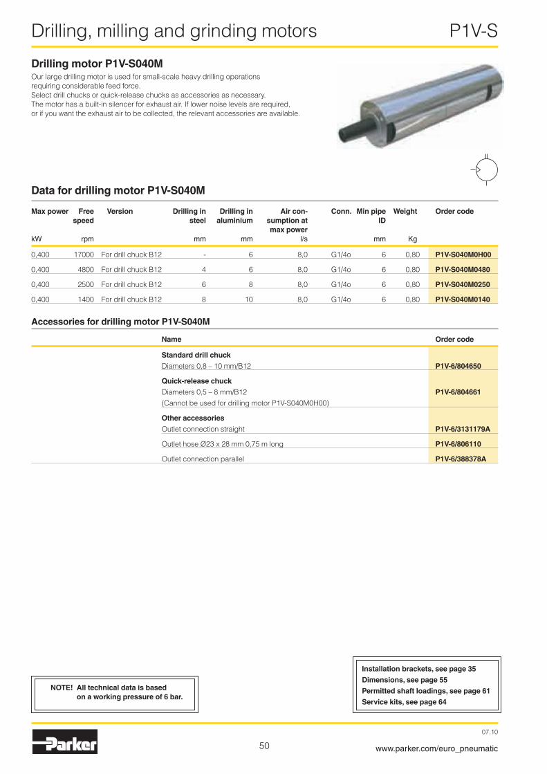
50
Drilling, milling and grinding motors P1V-S
07.10
www.parker.com/euro_pneumatic
Drilling motor P1V-S040MOur large drilling motor is used for small-scale heavy drilling operations requiring considerable feed force.Select drill chucks or quick-release chucks as accessories as necessary.The motor has a built-in silencer for exhaust air. If lower noise levels are required, or if you want the exhaust air to be collected, the relevant accessories are available.
Data for drilling motor P1V-S040M
Max power Free Version Drilling in Drilling in Air con- Conn. Min pipe Weight Order code speed steel aluminium sumption at ID max power kW rpm mm mm l/s mm Kg
0,400 17000 For drill chuck B1� - 6 8,0 G1/4o 6 0,80 P1V-S040M0H00
0,400 4800 For drill chuck B1� 4 6 8,0 G1/4o 6 0,80 P1V-S040M0480
0,400 �500 For drill chuck B1� 6 8 8,0 G1/4o 6 0,80 P1V-S040M0250
0,400 1400 For drill chuck B1� 8 10 8,0 G1/4o 6 0,80 P1V-S040M0140
Accessories for drilling motor P1V-S040M
Name Order code
Standard drill chuck Diameters 0,8 – 10 mm/B1� P1V-6/804650
Quick-release chuck Diameters 0,5 – 8 mm/B1� P1V-6/804661 (Cannot be used for drilling motor P1V-S040M0H00)
Other accessories Outlet connection straight P1V-6/3131179A
Outlet hose �3 x �8 mm 0,75 m long P1V-6/806110
Outlet connection parallel P1V-6/388378A
NOTE! All technical data is based on a working pressure of 6 bar.
Installation brackets, see page 35
Dimensions, see page 55
Permitted shaft loadings, see page 61
Service kits, see page 64
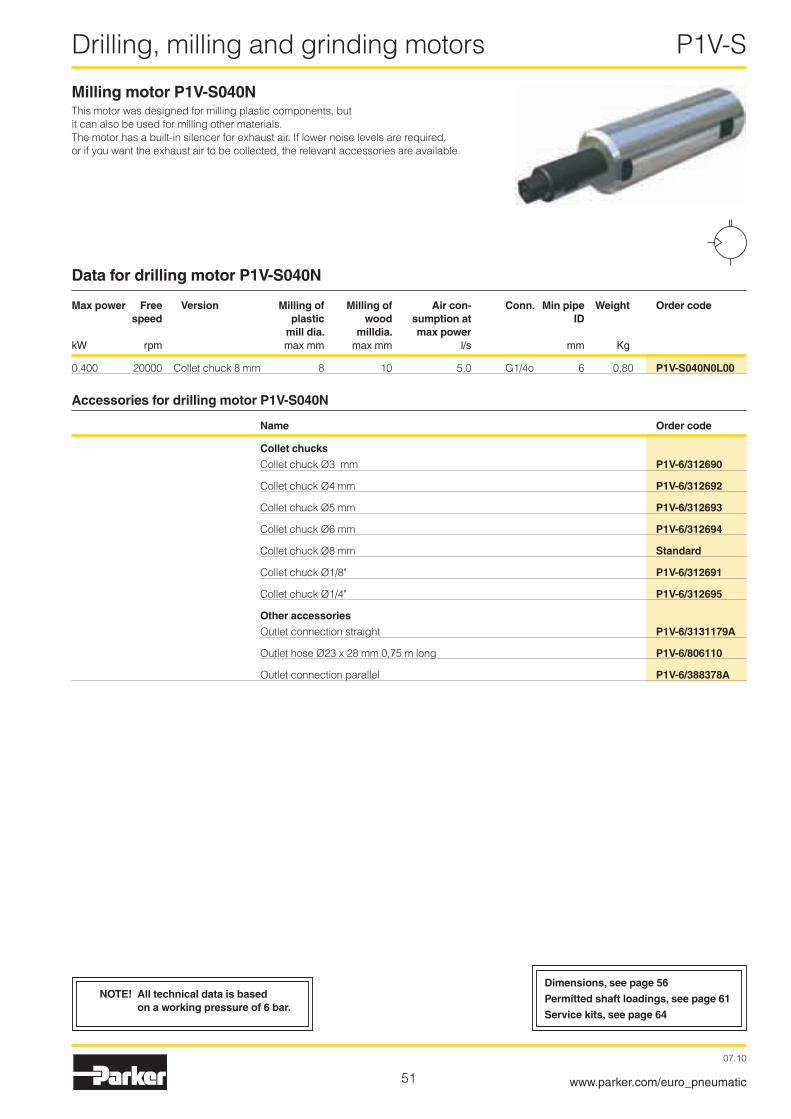
51
Drilling, milling and grinding motors P1V-S
07.10
www.parker.com/euro_pneumatic
Milling motor P1V-S040NThis motor was designed for milling plastic components, but it can also be used for milling other materials.The motor has a built-in silencer for exhaust air. If lower noise levels are required, or if you want the exhaust air to be collected, the relevant accessories are available.
Data for drilling motor P1V-S040N
Max power Free Version Milling of Milling of Air con- Conn. Min pipe Weight Order code speed plastic wood sumption at ID mill dia. milldia. max power kW rpm max mm max mm l/s mm Kg
0,400 �0000 Collet chuck 8 mm 8 10 5,0 G1/4o 6 0,80 P1V-S040N0L00
Accessories for drilling motor P1V-S040N
Name Order code
Collet chucks
Collet chuck Ø3 mm P1V-6/312690
Collet chuck Ø4 mm P1V-6/312692
Collet chuck Ø5 mm P1V-6/312693
Collet chuck Ø6 mm P1V-6/312694
Collet chuck Ø8 mm Standard
Collet chuck Ø1/8" P1V-6/312691
Collet chuck Ø1/4" P1V-6/312695
Other accessories Outlet connection straight P1V-6/3131179A
Outlet hose �3 x �8 mm 0,75 m long P1V-6/806110
Outlet connection parallel P1V-6/388378A
NOTE! All technical data is based on a working pressure of 6 bar.
Dimensions, see page 56
Permitted shaft loadings, see page 61
Service kits, see page 64

5�
Drilling, milling and grinding motors P1V-S
07.10
www.parker.com/euro_pneumatic
NOTE! All technical data is based on a working pressure of 6 bar.
NOTE! All technical data is based on a working pressure of 6 bar.
Dimensions, see page 56
Permitted shaft loadings, see page 61
Dimensions, see page 56
Permitted shaft loadings, see page 61
Service kits, see page 64
Grinding motor P1V-S009NThe grinding motor is used for small-scale point grinding and small-scale milling where the high speed is an advantage. It has proved to be very useful for drilling small holes and milling thin slits in PCBs in the electronics industry. In this application, the high speed means that the holes and slits are free of burrs on the underside.
Data for grinding motor P1V-S009N
Max power Free Version Point grinding diam. Milling diam. Air con- Conn. Min pipe Weight Order code speed max max sumption at ID max power kW rpm mm mm l/s mm Kg
0,090 100000 Collet chuck 3 mm 5 3 �,0 Pipe 6/4 4 0,3 P1V-S009N0A000
Grinding motor P1V-S020NThis grinding motor is used when larger-scale point grinding is required. The motor can also be used for light milling operations.The motor has a built-in silencer for exhaust air.
Data for grinding motor P1V-S020N
Max power Free Version Point grinding diam. Milling diam. Air con- Conn. Min pipe Weight Order code speed max max sumption at ID max power kW rpm mm mm l/s mm Kg
0,�00 30000 Collet chuck 6 mm �5 10 6,3 G1/4o 6 0,5 P1V-S020N0X00
Accessories for grinding motor P1V-S020N
Name Order code
Collet chucks
Collet chuck Ø3 mm P1V-6/312681
Collet chuck Ø4 mm P1V-6/312684
Collet chuck Ø5 mm P1V-6/312686
Collet chuck Ø6 mm Standard
Collet chuck Ø1/8" P1V-6/312682
Collet chuck Ø1/4" P1V-6/312689

53
Drilling, milling and grinding motors P1V-S
07.10
www.parker.com/euro_pneumatic
Drilling motor P1V-S008N
Drilling motor P1V-S017N
M8 x 0,75
M8 x 0,75Ø
10
Ø13
e8
2
50
A
B
Ø22
e9
M3
15
SW9 SW20
A B
P1V-S008N0Q00, P1V-S008N0700 98 96P1V-S008N0190, P1V-S008N0130 107 105
Clamping area
Outlet
Collet chuck Ø3
Inlet
200167
11833
2211
SW9SW10
Ø12
Ø25
d10
SW13
138
G1/
4
Ø24
,9
1447 22
2 m
G1/
2
Clamping area
Collet chuck Ø6
Inlet
Outlet
Outlet hose P1V-6/806112Seal for outlet hose P1V-6/823221
Outlet connection parallel P1V-6/302923A
CAD drawings on the InternetOur home page www.parker.com/euro_pneumatic includes the AirCad Drawing Library with �D and 3D drawings for the main versions.
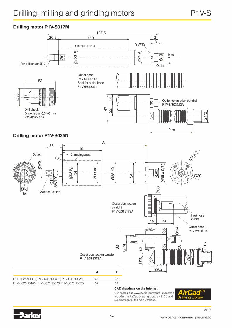
54
Drilling, milling and grinding motors P1V-S
07.10
www.parker.com/euro_pneumatic
Drilling motor P1V-S017M
Drilling motor P1V-S025N
A B
P1V-S0�5N0H00, P1V-S0�5N0480, P1V-S0�5N0�50 141 65P1V-S0�5N0140, P1V-S0�5N0070, P1V-S0�5N0035 157 81
187,511820,5
Ø10
Ø25
d10
SW13
138
G1/
4
Ø24
,9
1447 22
2 m
G1/
2
53
Ø30
Clamping area
Inlet
Outlet
Outlet hose P1V-6/806112Seal for outlet hose P1V-6/823221
Outlet connection parallel P1V-6/302923A
Drill chuck Dimensions 0,5 - 6 mmP1V-6/804655
For drill chuck B10
G1/4
SW
9
Ø12
SW
10
0,85
28A
B
Ø38
e8
Ø38
d9
34
34
SW17
M35
x 0
,75
M4
x 4
Ø30
Ø38
15 28
Ø20
e8
G1/
2
G1/
4
62
26R
18
29,5
Ø25
G1/
430
Clamping area
Inlet
Outlet
Collet chuck Ø6
Outlet connection straight P1V-6/313179A
Inlet hoseØ12/6
Outlet hoseP1V-6/806110
Outlet connection parallelP1V-6/388378A
CAD drawings on the InternetOur home page www.parker.com/euro_pneumatic includes the AirCad Drawing Library with �D and 3D drawings for the main versions.
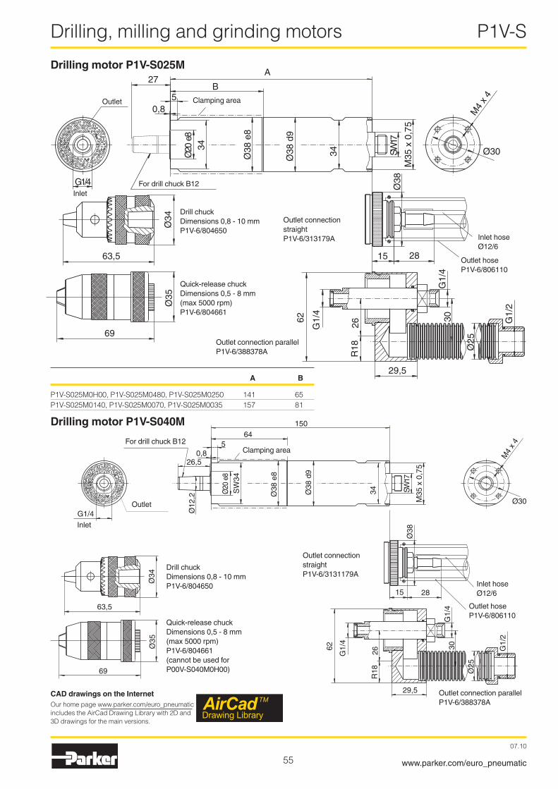
55
Drilling, milling and grinding motors P1V-S
07.10
www.parker.com/euro_pneumatic
Drilling motor P1V-S040M
Drilling motor P1V-S025M
G1/4
0,85
27A
B
Ø38
e8
Ø38
d9
34
34
SW17
M35
x 0
,75
M4
x 4
Ø30
Ø38
15 28
Ø20
e8
G1/
2
G1/
4
62
26R
18
29,5
Ø25
G1/
430
63,5
69
Ø34
Ø35
A B
P1V-S0�5M0H00, P1V-S0�5M0480, P1V-S0�5M0�50 141 65P1V-S0�5M0140, P1V-S0�5M0070, P1V-S0�5M0035 157 81
Clamping area
Inlet
Outlet
Outlet connection straight P1V-6/313179A
Outlet hose P1V-6/806110
Inlet hose Ø12/6
For drill chuck B12
Drill chuck Dimensions 0,8 - 10 mmP1V-6/804650
Outlet connection parallelP1V-6/388378A
Quick-release chuckDimensions 0,5 - 8 mm(max 5000 rpm)P1V-6/804661
0,85
64150
Ø12
,2
Ø20
e8
SW
34
Ø38
e8
Ø38
d9
34 SW17
G1/4
M35
x 0
,75
M4
x4
Ø30G
1/2
G1/
4
62
26R
18
29,5
63,5
69 Ø25
26,5
Ø38
Ø34
Ø35
15 28
G1/
430
Drill chuck Dimensions 0,8 - 10 mmP1V-6/804650
Quick-release chuckDimensions 0,5 - 8 mm(max 5000 rpm)P1V-6/804661(cannot be used for P00V-S040M0H00)
Inlet
Outlet
For drill chuck B12
Outlet connection straightP1V-6/3131179A
Outlet connection parallelP1V-6/388378A
Inlet hoseØ12/6
Outlet hoseP1V-6/806110
Clamping area
CAD drawings on the InternetOur home page www.parker.com/euro_pneumatic includes the AirCad Drawing Library with �D and 3D drawings for the main versions.

56
Drilling, milling and grinding motors P1V-S
07.10
www.parker.com/euro_pneumatic
142
16
10
Ø3
Ø21
d9
Ø32
d9
Ø30 Ø20
,5
21
490,4 m
2 m51
SW
7
SW
9 4,25
Pip
e Ø
6/4
Inle
t
Outlet
Clamping area
Grinding motor P1V-S009N0A000
Grinding motor P1V-S020N0X000
Milling motor P1V-S040NSW12 SW17 SW36 SW36 SW17
G1/
4
Ø20
8
103091
179
3 x 45°
Ø38
e8
Ø19
Ø38
15 28
G1/
2
G1/
4
62
26R
18
29,5
Ø25
G1/
430
Clamping area
Outlet
Inlet
Outlet connection straightP1V-6/313179A
Inlet hoseØ12/6
Outlet hoseP1V-6/806110
Outlet connection parallelP1V-6/388378A
24 82
153
34 13
8
Ø28
d11
G1/
4
Ø28
e8
SW10
Ø12
SW9
Inlet
Outlet
Clamping areaCollet chuck Ø6
CAD drawings on the InternetOur home page www.parker.com/euro_pneumatic includes the AirCad Drawing Library with �D and 3D drawings for the main versions.

57
Stainless Steel Air Motors P1V-S
07.10
www.parker.com/euro_pneumatic
Theoretical calculationsThis section provides you with the background you need in order to select the right air motor for common applications.The first four parts explain the direct physical relationships between:
Force - Torque - Speed - Power Requirement
Before selecting an air motor, you need to know the torque required by the application at the necessary speed. Some-times, the torque and the speed are not known but the power requirement and the speed of movement are. You can use the following formulas to calculate the speed and torque.
Power The power requirement is always calculated in N.
Formula:F = m x g
F = power in Nm = mass in kgg = gravitation (9,81) in m/s�
In this example, the mass is 150 kgF = 150 x 9,81 NF = 1470 N
TorqueTorque is the force applied to produce rotational motion (rota-tional force) or the force applied in the opposite direction. It is the product of the rotational force F and the distance from the pivot point (radius or moment arm)
Formula:M = m x g x r
M = torque in Nmm = mass in kgg = gravitation (9,81) in m/s�
r = radius or moment arm in m
In this example, the drum diameter is 300 mm, which means the radius r = 0,15 m, and the mass is 150kg.M = 150 x 9,81 x 0,15 NmM = ��1 Nm
SpeedThe required motor speed can be calculated if the speed of movement and the radius (diameter) are known.
n = v x 60/(� x π x r)
n = motor speed in rpmv = speed of movement in m/secr = radius in mπ = constant (3,14)
In this example, the speed of movement is 1,5 m/s and the drum diameter is 300 m (radius r = 0,15 m)
n = 1,5 x 60/(� x π x 0,15) rpmn = 96 rpm
Power RequirementThe power requirement can be calculated if the motor speed and torque are known.
P = M x n/9550
P = power in kWM = torque in Nmn = rpm9550 = conversion factor
In this example, a torque of 1,�5 Nm is required at a speed of 1500 rpm.P = 1,�5 x 1500/9550P = 0,196 kW or approx. �00 Watt
150 kg
rM
r
v
n
150 kg
F
M, n

58
Stainless Steel Air Motors P1V-S
07.10
www.parker.com/euro_pneumatic
Frictional Forces between two ObjectsA frictional force always occurs between two objects with surfaces in contact with each other. It is always exerted against the direction of movement.
The frictional force is either static or kinetic. When selecting an air motor, we need to consider the larger of the two forces, static or kinetic.
The size of the static frictional force or the kinetic frictional force is the product of the normal force Fn and the coefficient of static friction (µ0), or the product of the normal force Fn and the coefficient of kinetic friction (µ).The size of the contact surface between the objects is irrel-evant.
Formula:
Fstatic = Fn x µ0Fkinetic = Fn x µ
Fn = m x g
Fstatic = static friction in NFkinetic = kinetic friction in NFn = force from object in Nm = mass in kgg = gravitation (9,81) in m/s�
Material Coefficient of static friction µ0 Dry Lubricated
Bronze Bronze 0,�8 0,11Bronze Grey iron 0,�8 0,16Grey iron Grey iron - 0,16Steel Bronze 0,�7 0,11Steel Ice 0,0�7 -Steel Grey iron 0,�0 0,10Steel Steel 0,15 0,10Steel White metal - -Wood Ice - -Wood Wood 0,65 0,16Leather Grey iron 0,55 0,��Brake lining Steel - -Steel Nylon (polyamide) - -
Material Coefficient of kinetic friction µ Dry Lubricated
Bronze Bronze 0,� 0,06Bronze Grey iron 0,�1 0,08Grey iron Grey iron - 0,1�Steel Bronze 0,18 0,07Steel Ice 0,014 -Steel Grey iron 0,16 0,05Steel Steel 0,10 0,05Steel White metal 0,�0 0,04Wood Ice 0,035 -Wood Wood 0,35 0,05Leather Grey iron 0,�8 0,1�Brake lining Steel 0,55 0,40Steel Nylon (polyamide) 0,5 0,10
Example: A steel component with a weight of 500 kg is to be pulled across bronze plate without lubrication. What will the frictional force be when the component moves?
Fstatic = Fn x µ0
Fkinetic = Fn x µ
Fstatic = 500 x 9,81 x 0,�7 = 13�4 N
Fkinetic = 500 x 9,81 x 0,18 = 883 N
The static frictional force should always be compared with the force provided by the motor when it starts.
Kinetic Resistance
Kinetic resistance is a term expressing the total resistance, consisting of rolling resistance and the frictional force in the bearing
Formula:
FF = µF x Fn
FF = kinetic resistance in N µF = coefficient of kinetic resistance
Fn = force from object in N
Coefficient of kinetic resistance:
Object Coefficient of kinetic resistance
Railway vehicle on steel rails 0,0015 to 0,0030Vehicle with rubber wheel on asphalt 0,015 to 0,03
Example:
A railway carriage with a weight of � tonnes is to move over flat rails. What will the kinetic resistance be?
FF = µF x FnFF = 0,0030 x � x 1000 x 9,81FF = 4,86 N
FnFF
Fstatic Fkinetic
Fn Ffriction

59
Stainless Steel Air Motors P1V-S
07.10
www.parker.com/euro_pneumatic
Moving a component over a base, with friction between them
The force required to move the component consists of two parts - a frictional force to move the component over the base, and an acceleration force
F tot = Ffriction + Facc
Facc = m x a
F tot = Ffriction + m x a
F tot = the total force required in order to move the object in N
Ffriction = frictional force in N (either Fstatic or Fkinetic depending on which is the greater force)
Facc = acceleration force in N
m = mass in kg
a = acceleration in m/s�
A steel component weighing 500 kg is to be pulled over a dry steel plate with an acceleration of 0,1 m/s�. What is the total force required to produce this movement?
F tot = Fkinetic + Facc
F tot = Fkinetic + m x a
F tot = Fn x u + m x a
F tot = 500 x 9,81 x 0,15 + 500 x 0,1
F tot = 735,75 + 50
F tot = 785,75 N
Answer: A force of 780 N is required to produce this move-ment.
Fn
Ffriction
Ftotal
ma
Facc
F kinetic resistance
am
Fn FF
Facc
Moving a carriage over rails, with kinetic resistance between them
The force required to move the component consists of two parts - a kinetic resistance to move the component over the base, and an acceleration force
F tot = Fkinetic resistance + Facc
Facc = m x a
F tot = Fkinetic resistance + m x a
F tot = the total force required in order to move the object in N
Fkinetic resistance = total kinetic resistance in N
Facc = acceleration force in N
m = mass in kg
a = acceleration in m/s�
A carriage weighing �500 kg is to be pulled over steel rails with an acceleration of 0,� m/s�. What is the total force required to produce this movement?
F tot = Fkinetic resistance + Facc
F tot = uF x FN + m x a
F tot = 0,0030 x �500 x 9,81 + �500 x 0,�
F tot = 6,1 + 500
F tot = 506 N
Answer: A force of 510 N is required to produce this move-ment.
In practiceThese calculations only produce values as they would be under optimum conditions. There must be no inclines in either direction. In applications using carriages, the rails must be perfectly flat without any inclines, the wheels must be perfectly round and there must be nothing on the rails (grains of sand, etc.). There must also be no effects from wind, etc.
In addition, there is always uncertainty with regard to the compressed air supply. How can we guarantee a pressure of 6 bar to the inlet port of the air motor?Tip: calculate the required theoretical values for the air motor and assume a safety factor of 10 for the frictional force or kinetic resistance, and add this to the acceleration force. If the motor proves to be too powerful in practice, the supply air can always be regulated by throttling or pressure regulation. If you select a motor that is not powerful enough, on the other hand, the only option is to replace it.
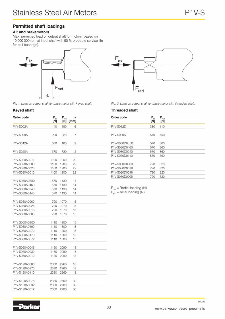
60
Stainless Steel Air Motors P1V-S
07.10
www.parker.com/euro_pneumatic
Keyed shaft
Order code Fax Frad a [N] [N] [mm]
P1V-S00�A 140 180 6
P1V-S008A �00 ��0 7
P1V-S01�A 380 160 9
P1V-S0�0A 570 7�0 1�
P1V-S0�0A0011 1100 1�00 ��P1V-S0�0A0006 1100 1�00 ��P1V-S030A00�3 1100 1�00 ��P1V-S030A0010 1100 1�00 ��
P1V-S030A0E50 570 1130 14P1V-S030A0460 570 1130 14P1V-S030A0�40 570 1130 14P1V-S030A0140 570 1130 14
P1V-S030A0060 790 1070 15P1V-S030A00�8 790 1070 15P1V-S030A0018 790 1070 15P1V-S030A0005 790 1070 15
P1V-S060A0E00 1110 1300 15P1V-S060A0400 1110 1300 15P1V-S060A0�70 1110 1300 15P1V-S060A0170 1110 1300 15P1V-S060A007� 1110 1300 15
P1V-S060A0048 1130 �090 18 P1V-S060A0030 1130 �090 18 P1V-S060A0010 1130 �090 18
P1V-S1�0A0800 �330 ��60 18P1V-S1�0A0�70 �330 ��60 18P1V-S1�0A0110 �330 ��60 18
P1V-S1�0A0078 �330 �700 30P1V-S1�0A003� �330 �700 30P1V-S1�0A001� �330 �700 30
rad
axFax
Frad
a
Fig 1: Load on output shaft for basic motor with keyed shaft. Fig. 2: Load on output shaft for basic motor with threaded shaft.
Permitted shaft loadingsAir and brakemotorsMax. permitted load on output shaft for motors (based on 10 000 000 rpm at input shaft with 90 % probable service life for ball bearings).
Threaded shaft
Order code Fax Frad [N] [N]
P1V-S01�D 380 110
P1V-S0�0D 570 450
P1V-S030D0E50 570 860P1V-S030D0460 570 860P1V-S030D0�40 570 860P1V-S030D0140 570 860
P1V-S030D0060 790 8�0P1V-S030D00�8 790 8�0P1V-S030D0018 790 8�0P1V-S030D0005 790 8�0
Frad = Radial loading (N)Fax = Axial loading (N)

61
Drilling, milling and grinding motors P1V-S
07.10
www.parker.com/euro_pneumatic
Permitted shaft loadingsDrilling, milling and grinding motorsMax. permitted load on output shaft for motors (based on 10 000 000 rpm at input shaft with 90 % probable service life for ball bearings).
Drilling motors with collet chuck
Order code Fax Frad a [N] [N] [mm]
P1V-S008N �00 75 �5
P1V-S017N 380 50 �5
P1V-S0�5N 750 �60 �5
Drilling motors with drill chuck
Order code Fax Frad a [N] [N] [mm]
P1V-S017M 380 35 60
P1V-S0�5M 380 150 70
P1V-S040M 750 150 70
Milling motor
Order code Fax Frad a [N] [N] [mm]
P1V-S040N* 30 �50 �5
Grinding motors
Order code Fax Frad a [N] [N] [mm]
P1V-S009N* � 10 �5
P1V-S0�0N* 16 70 �5
Frad = Radial loading (N)Fax = Axial loading (N)
* For the milling motor and grinding motor, these loadings are calculated for 1000 hours of operation
Fig 3: Load on output shaft for drilling, milling and grinding motors.
F
F
F
F
ax
ax
rad
rad
a
a
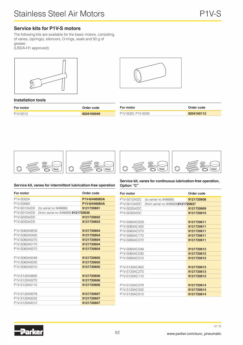
6�
Stainless Steel Air Motors P1V-S
07.10
www.parker.com/euro_pneumatic
Service kits for P1V-S motorsThe following kits are available for the basic motors, consisting of vanes, (springs), silencers, O-rings, seals and 50 g of grease: (USDA-H1 approved):
Service kit, vanes for continuous lubrication-free operation, Option ”C”
For motor Order code
P1V-S01�A/DC (to serial no 948688) 9121720608P1V-S01�A/DC (from serial no 948689) 9121720637P1V-S0�0A/DC 9121720609P1V-S030A/DC 9121720610
P1V-S060ACE00 9121720611P1V-S060AC400 9121720611P1V-S060AC�70 9121720611P1V-S060AC170 9121720611P1V-S060AC07� 9121720611
P1V-S060AC048 9121720612P1V-S060AC030 9121720612P1V-S060AC010 9121720612
P1V-S1�0AC800 9121720613P1V-S1�0AC�70 9121720613P1V-S1�0AC110 9121720613
P1V-S1�0AC078 9121720614P1V-S1�0AC03� 9121720614P1V-S1�0AC01� 9121720614
Service kit, vanes for intermittent lubrication-free operation
For motor Order code
P1V-S00�A P1V-6/446083AP1V-S008A P1V-6/446084AP1V-S01�A/D0 (to serial no 948688) 9121720601P1V-S01�A/D0 (from serial no 948689) 9121720636P1V-S0�0A/D0 9121720602P1V-S030A/D0 9121720603
P1V-S060A0E00 9121720604P1V-S060A0400 9121720604P1V-S060A0�70 9121720604P1V-S060A0170 9121720604P1V-S060A007� 9121720604
P1V-S060A0048 9121720605P1V-S060A0030 9121720605P1V-S060A0010 9121720605
P1V-S1�0A0800 9121720606P1V-S1�0A0�70 9121720606P1V-S1�0A0110 9121720606
P1V-S1�0A0078 9121720607P1V-S1�0A003� 9121720607P1V-S1�0A001� 9121720607
Installation tools
For motor Order code
P1V-S01� 8204160049
For motor Order code
P1V-S0�0, P1V-S030 8204160112
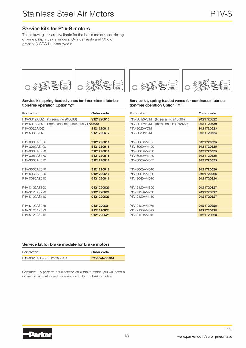
63
Stainless Steel Air Motors P1V-S
07.10
www.parker.com/euro_pneumatic
Service kits for P1V-S motorsThe following kits are available for the basic motors, consisting of vanes, (springs), silencers, O-rings, seals and 50 g of grease: (USDA-H1 approved):
Service kit, spring-loaded vanes for intermittent lubrica-tion-free operation Option “Z”
For motor Order code
P1V-S01�A/DZ (to serial no 948688) 9121720615P1V-S01�A/DZ (from serial no 948689) 9121720638P1V-S0�0A/DZ 9121720616P1V-S030A/DZ 9121720617
P1V-S060AZE00 9121720618P1V-S060AZ400 9121720618P1V-S060AZ�70 9121720618P1V-S060AZ170 9121720618P1V-S060AZ07� 9121720618
P1V-S060AZ048 9121720619P1V-S060AZ030 9121720619P1V-S060AZ010 9121720619
P1V-S1�0AZ800 9121720620P1V-S1�0AZ�70 9121720620P1V-S1�0AZ110 9121720620
P1V-S1�0AZ078 9121720621P1V-S1�0AZ03� 9121720621P1V-S1�0AZ01� 9121720621
Service kit, spring-loaded vanes for continuous lubrica-tion-free operation Option ”M”
For motor Order code
P1V-S01�A/DM (to serial no 948688) 9121720622P1V-S01�A/DM (from serial no 948689) 9121720639P1V-S0�0A/DM 9121720623P1V-S030A/DM 9121720624
P1V-S060AME00 9121720625P1V-S060AM400 9121720625P1V-S060AM�70 9121720625P1V-S060AM170 9121720625P1V-S060AM07� 9121720625
P1V-S060AM048 9121720626P1V-S060AM030 9121720626P1V-S060AM010 9121720626
P1V-S1�0AM800 9121720627P1V-S1�0AM�70 9121720627P1V-S1�0AM110 9121720627
P1V-S1�0AM078 9121720628P1V-S1�0AM03� 9121720628P1V-S1�0AM01� 9121720628
Service kit for brake module for brake motors
For motor Order code
P1V-S0�0AD and P1V-S030AD P1V-6/446096A
Comment: To perform a full service on a brake motor, you will need a normal service kit as well as a service kit for the brake module
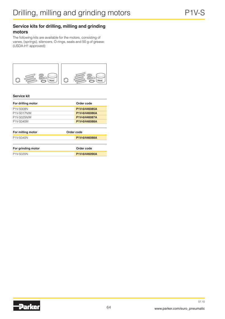
64
Drilling, milling and grinding motors P1V-S
07.10
www.parker.com/euro_pneumatic
Service kit
For drilling motor Order code
P1V-S008N P1V-6/446085AP1V-S017N/M P1V-6/446086AP1V-S0�5N/M P1V-6/446087AP1V-S040M P1V-6/446088A
For milling motor Order code
P1V-S040N P1V-6/446088A
For grinding motor Order code
P1V-S0�0N P1V-6/446090A
Service kits for drilling, milling and grinding motorsThe following kits are available for the motors, consisting of vanes, (springs), silencers, O-rings, seals and 50 g of grease: (USDA-H1 approved):

65
Stainless Steel Air Motors P1V-S
07.10
www.parker.com/euro_pneumatic
4020
7 bar6 bar5 bar4 bar3 bar
60 80 100
160
120
140
200
220
240
180
100
100
120
20
40
60
80
20
40
60
80
M
M [%]
n [%]
Q
P
Q [%], P [%]
Torque, power and air consumption graphs
P = power Q = air consumption M = torque n = speed
The curves in this graph are a combination of the torque, power and air consumption graphs on page 6. The values from the correction diagram on page 7 have also been used for the curves for the different pressure values. The graph also shows that is it very important to ensure that the pressure supplied to the inlet port of the motor is correct, in order to allow the motor to work at maximum capacity. If the valve supplying a large motor is too small, or if the supply line is underspecified, the pressure at the inlet port may be so low that the motor is unable to do its work. One solution would be to upgrade the valve and supply system, or alternatively you could replace the motor with a smaller motor with lower air consumption. The result would be increased pressure at the inlet port, which means that the smaller motor could carry out the necessary work. However, you may need to select a smaller motor with a lower free speed in order to obtain sufficient torque at the outgoing shaft.

66
Stainless Steel Air Motors P1V-S
07.10
www.parker.com/euro_pneumatic
Notes

AE – United Arab Emirates, Abu Dhabi Tel: +971 2 67 88 587
AR – Argentina, Buenos Aires Tel: +54 3327 44 4129
AT – Austria, Wiener Neustadt Tel: +43 (0)2622 23501-0
AT – Austria, Wiener Neustadt (Eastern Europe) Tel: +43 (0)2622 23501 970
AU – Australia, Castle Hill Tel: +61 (0)2-9634 7777
AZ – Azerbaijan, Baku Tel: +994 50 2233 458
BE – Belgium, Nivelles Tel: +32 (0)67 280 900
BR – Brazil, Cachoeirinha RS Tel: +55 51 3470 9144
BY – Belarus, Minsk Tel: +375 17 209 9399
CA – Canada, Milton, Ontario Tel: +1 905 693 3000
CH – Switzerland See Germany
CN – China, Shanghai Tel: +86 21 5031 2525
CN – China, Beijing Tel: +86 10 6561 0520
CZ – Czech Republic, Klecany Tel: +420 284 083 111
DE – Germany, Kaarst Tel: +49 (0)2131 4016 0
DK – Denmark, Ballerup Tel: +45 43 56 04 00
ES – Spain, Madrid Tel: +34 902 33 00 01
FI – Finland, Vantaa Tel: +358 (0)20 753 2500
FR – France, Contamine-sur-Arve Tel: +33 (0)4 50 25 80 25
GR – Greece, Athens Tel: +30 210 933 6450
HK – Hong Kong Tel: +852 2428 8008
HU – Hungary, Budapest Tel: +36 1 220 4155
IE – Ireland, Dublin Tel: +353 (0)1 466 6370
IN – India, Mumbai Tel: +91 22 6513 7081-85
IT – Italy, Corsico (MI) Tel: +39 02 45 19 21
JP – Japan, Fujisawa Tel: +(81) 4 6635 3050
KR – South Korea, Seoul Tel: +82 2 559 0400
KZ – Kazakhstan, Almaty Tel: +7 3272 505 800
LV – Latvia, Riga Tel: +371 74 52601
MX – Mexico, Apodaca Tel: +52 81 8156 6000
MY – Malaysia, Subang Jaya Tel: +60 3 5638 1476
NL – The Netherlands, Oldenzaal Tel: +31 (0)541 585 000
NO – Norway, Ski Tel: +47 64 91 10 00
NZ – New Zealand, Mt Wellington Tel: +64 9 574 1744
PL – Poland, Warsaw Tel: +48 (0)22 573 24 00
PT – Portugal, Leca da Palmeira Tel: +351 22 999 7360
RO – Romania, Bucharest Tel: +40 21 252 1382
RU – Russia, Moscow Tel: +7 495 645-2156
SE – Sweden, Spånga Tel: +46 (0)8 59 79 50 00
SG – Singapore Tel: +65 6887 6300
Sales Offices
Catalogue PDE2554TCUK-ul. December 2007
Your local authorized Parker distributor
SL – Slovenia, Novo Mesto Tel: +386 7 337 6650
SK – Slovakia See Czech Republic
TH – Thailand, Bangkok Tel: +662 717 8140
TR – Turkey, Merter/Istanbul Tel: +90 212 482 91 06 or 07
TW – Taiwan, Taipei Tel: +886 2 2298 8987
UA – Ukraine, Kyiv Tel +380 44 494 2731
UK – United Kingdom, Warwick Tel: +44 (0)1926 317 878
US – USA, Cleveland Tel: +1 216 896 3000
US – USA, Miami (Pan American Division) Tel: +1 305 470 8800
VE – Venezuela, Caracas Tel: +58 212 238 5422
ZA – South Africa, Kempton Park Tel: +27 (0)11 961 0700
© 2007 Parker Hannifin Corporation. All rights reserved.
Parker Hannifin Ltd Tachbrook Park Drive Tachbrook Park, Warwick CV34 6TUUnited Kingdom Tel.: +44 (0) 1926 317 878 Fax: +44 (0) 1926 317 855www.parker.com/eu