atlas copco air motors - air-mech.co.nz full range of compact, high performance air motors atlas...
TRANSCRIPT

A full range of compact, high performance air motors
Atlas CopcoAir motors

2 AT L A S C O P C O A I R M O T O R S

AIR MOTOR FEATURESAND CHARACTERISTICS• Air motors are compact and lightweight. An air motor
weighs only a quarter as much and occupies only one sixth of the space of an electric motor of equivalent output power. Air motors develop far more power relative to size and weight than most other motor types.
• Air motors can be stalled indefinitely without overheating or sustaining any other damage. They can be started and stopped repeatedly to an unlimited extent.
• Torque, speed and direction of rotation can be changed easily using simple control methods.
• Output inherently adjusts to match the applied load.
• Controllable over a wide speed range.
• Virtually unaffected by hostile environment.
• Smooth start-up to minimize ”shock” loading on transmission components.
ATLAS COPCO – AIR MOTORS• Leading the industry in development and innovation.
• Offering a comprehensive range of standard air motors.
• A premier supplier of air motors engineered to meet customer requirements.
• Delivering orders, on time, to customer schedules.
• Offering a truly worldwide service.
Atlas Copco air motors – the natural choice for design engineers in the industries of today and tomorrow.
Our air motors are explosion proof certified, in compliance with the European Union´s ATEX directive 2014/34/EU. For equipment used in potentially explosive environments.
AT L A S C O P C O A I R M O T O R S 3

www.atlascopco.com/airmotorsVisit our website and browse through our on-line catalogue. You’ll find comprehensive technical information as well as details of accessories, spare parts and dimensional drawings. You can also subscribe to our news.
Want to know more about air motors?
In this pocket guide you will find information about function, design, motor selection and installation. Use the Ordering No. 9833 9067 01.
Selecting the right motor has never been easier!
Just enter the required working point for the application and the most suitable motor will automatically be selected. For the selection use the Atlas Copco selection tool.
Air motor selection program, available at
www.atlascopco.com/airmotors
ADDITIONAL INFORMATIONABOUT OUR AIR MOTORS
4 AT L A S C O P C O A I R M O T O R S

LZB vane motors introduction• Shaft loading• Mounting• Connection• Hose dimensions• LZB vane motors: data, specification and performance curves• Accessories for air motors
Choosing your motor• The working point• Atlas Copco air motor selection guide• Starting torque and stall torque• Accelerating a load to speed• Shaft loading• Silencing• Temperature• Hostile environments• Atlas Copco air motor selection program
Installing your air motor• Air lines• Recommended hose connectors• Air preparation• Lubrication• Control valves for air motors• Installation examples• Introduction to Atlas Copco air motors and gear units
Introducing the air motor• Methods of modifying motor output• Using the catalogue
LZL vane motors introduction• Shaft loading• Mounting• Connection• Hose dimensions• LZL vane motors: data, specification and performance curves• LZL vane motor/gear unit combinations• LZL air motors: with helical gear units data, specification and performance curves• Accessories for LZL motors
ATEX• Explosion prevention guidelines• ATEX code definition
CONTENTS
6 – 7
8 – 9
10 – 13
14 – 69
70 – 88
89 – 90
AT L A S C O P C O A I R M O T O R S 5

TorqueNm
Speed r/min
Stalltorque
Minstartingtorque
Torque
Power
INTRODUCING THE AIR MOTORThe air motor is one of the toughest and most versatile power units available to today´s design engi-
neer. It is easy to control over a wide speed range, and it produces maximum torque where it is often
most needed – at start up.
However, by simply regulating the air supply, using the techniques of throttling or pressure regulation, the output of an air motor can easily be modified.
The free speed and torque can be regulated down to 50% for an LZB air motor. The free speed for an LZL can be regu-lated down to 10% and the torque can be regulated down to 20%. The shaded areas in Figure 2 illustrate this.
The performance curves for an ungoverned air motor opera-ting at a constant air pressure are illustrated in Figure 3.
Torque[Nm]
Speed [r/min]
Torque100%
100
Speed 100%50 100
50
Torque100%
100
Speed 100%10 50 100
20
50
LZB LZL
Figure 2
The use of gear units
Air motors operate at high speed and, although they can be controlled over a wide speed range, the output characteris-tics are not always suitable for the application. To achieve the required output an appropriate gear unit can be selected. The ability to change the output by use of a gear unit is illustrated in Figure 4.
Figure 3
TorqueNm
4:1
2:1
1:1
Speed r/min1:1, 2:1, 4:1 = gear ratios
Torque
Power
The planetary and helical gear units used by Atlas Copco have a high level of efficiency that can be assumed to be 100%. The power output remains virtually unchanged also when gears are used.
Figure 4
Figure 1
The performance of an air motor is dependent on the inlet pressure. At a constant inlet pressure, ungoverned air motors exhibit the characteristic linear output torque/speed relations-hip. Figure 1.
It should be noted that all vane air motors produce a variable starting torque, due to the position of the vanes in the motor when it is started. The variation differs between motor types and must be checked on an individual basis.
The power that an air motor produces is a function of tor-que and speed. All ungoverned air motors produce the same characteristic power curve, with maximum power occurring at around 50% of the free speed. The torque produced at this point is often referred to as ”torque at maximum output.”
6 AT L A S C O P C O A I R M O T O R S

Throttling
A throttle is usually fitted into the motor´s inlet, although it can also be complemented with some throttling at the exhaust. You should never create a back pressure above 1 bar at the exhaust.
Pressure regulation
When using a pressure regulator it is mostly fitted into the motor´s inlet hose. The use of pressure regulation is ideal when control of the stall torque is required and a high star-ting torque is not so important, Figure 6.
TorqueNm
Speed r/min Figure 5
Torque%
Speed %
Operating pressure
7 bar
6 bar
5 bar
4 bar
3 bar
100
100
Figure 6
Par[Nm]
Velocidad [r/min]
Understanding the performance curves
The output of an air motor is most clearly seen from its perfor-mance curves, Figure 8. For each motor/gear unit the power, torque and air consumption are shown as a function of speed.
The diagrams shown apply to an inlet pressure of 6.3 bar, to calculate performance at other pressures refer to page 8 in this catalogue.
Motor data, specification and performance curves
For each Atlas Copco motor/gear unit combination the following information is presented in this catalogue.
1. Tabular data – summary of main performance parameters.
2. Dimensional drawings.
3. Performance curves.
Notes on performance data
The performance data stated in this catalogue is valid for an air supply pressure of 6.3 bar (91 psi), gauge. Air consump-tion values are for free air delivery – (i.e., the volume the con-sumed air would occupy if allowed to expand to atmospheric pressure).
The direction of rotation for a motor is always stated looking from the back of the motor. Figure 7 illustrates clockwise rotation.
Figure 7
NOTE: The starting torque produced by an air motor is variable and depends on vane position. These diagrams do not indicate the starting torque – this can be obtained from data tables, where the minimum value is shown.
Figure 8
TorqueNmPowerkW
Maxoutput
Torqueat maxoutput
Torque
Power
Speed r/min
Air. cons.
Air cons.l/s
METHODS OF MODIFYING MOTOR OUTPUT
USING THE CATALOGUE
More information about motor selection and installation in the catalogue.
AT L A S C O P C O A I R M O T O R S 7
TorqueNm
Speed r/min
Desired working point
Torque with standardmotor at 6.3 bar (91 psi)
Torque with throttledmotor
Torque with pressureregulator
CHOOSING YOUR MOTOR
TorqueNm
0.4
0.3
0.2
0.1
200Speedr/min
Air cons.l/s
PowerkW
20
16
12
8
4
10
8
6
4
2
400 600 800 200Speedr/min
Air cons.l/s
24
20
16
12
8
4
10
8
6
4
2
400 600
TorqueNm
0.4
0.3
0.2
0.1
PowerkW
LZB33-L-A007-11 LZB 33 A005
Figure 7
Figure 6
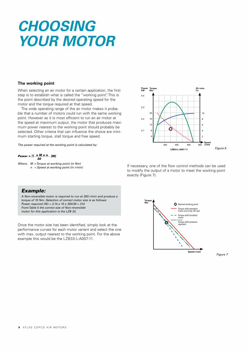
If necessary, one of the flow control methods can be used to modify the output of a motor to meet the working point exactly (Figure 7).
The working point
When selecting an air motor for a certain application, the first step is to establish what is called the “working point”. This is the point described by the desired operating speed for the motor and the torque required at that speed.
The wide operating range of the air motor makes it proba-ble that a number of motors could run with the same workingpoint. However as it is most efficient to run an air motor at the speed at maximum output, the motor that produces maxi-mum power nearest to the working point should probably beselected. Other criteria that can influence the choice are mini-mum starting torque, stall torque and free speed.
The power required at the working point is calculated by:
Power = π x M x n [W] 30
Where, M = Torque at working point (in Nm) n = Speed at working point (in r/min)
Example:A Non-reversible motor is required to run at 300 r/min and produce a torque of 10 Nm. Selection of correct motor size is as follows: Power required (W) = 3.14 x 10 x 300/30 = 314From Table 5 the correct size of Non-reversible motor for this application is the LZB 33.
Once the motor size has been identified, simply look at the performance curves for each motor variant and select the one with max. output nearest to the working point. For the above example this would be the LZB33-L-A007-11.
8 AT L A S C O P C O A I R M O T O R S
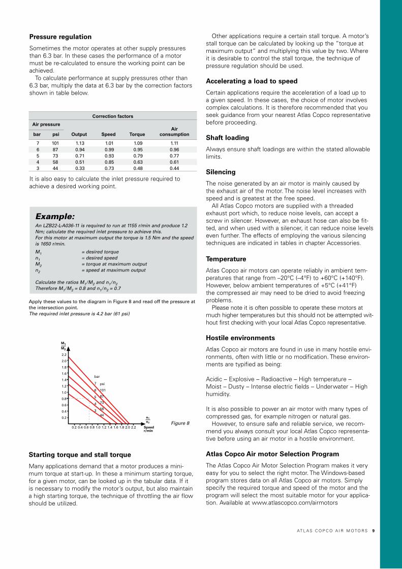
Apply these values to the diagram in Figure 8 and read off the pressure at the intersection point.The required inlet pressure is 4.2 bar (61 psi)
Pressure regulation
Sometimes the motor operates at other supply pressures than 6.3 bar. In these cases the performance of a motor must be re-calculated to ensure the working point can be achieved.
To calculate performance at supply pressures other than 6.3 bar, multiply the data at 6.3 bar by the correction factors shown in table below.
It is also easy to calculate the inlet pressure required to achieve a desired working point.
Example:An LZB22-L-A036-11 is required to run at 1155 r/min and produce 1.2 Nm; calculate the required inlet pressure to achieve this.For this motor at maximum output the torque is 1.5 Nm and the speed is 1650 r/min.
M1 = desired torque n1 = desired speedM2 = torque at maximum outputn2 = speed at maximum output
Calculate the ratios M1/M2 and n1/n2 Therefore M1/M2 = 0.8 and n1/n2 = 0.7
Starting torque and stall torque
Many applications demand that a motor produces a mini-mum torque at start-up. In these a minimum starting torque, for a given motor, can be looked up in the tabular data. If it is necessary to modify the motor’s output, but also maintain a high starting torque, the technique of throttling the air flow should be utilized.
Other applications require a certain stall torque. A motor’s stall torque can be calculated by looking up the ”torque at maximum output“ and multiplying this value by two. Where it is desirable to control the stall torque, the technique of pressure regulation should be used.
Accelerating a load to speed
Certain applications require the acceleration of a load up to a given speed. In these cases, the choice of motor involves complex calculations. It is therefore recommended that you seek guidance from your nearest Atlas Copco representative before proceeding.
Shaft loading
Always ensure shaft loadings are within the stated allowable limits.
Silencing
The noise generated by an air motor is mainly caused by the exhaust air of the motor. The noise level increases with speed and is greatest at the free speed.
All Atlas Copco motors are supplied with a threaded exhaust port which, to reduce noise levels, can accept a screw in silencer. However, an exhaust hose can also be fit-ted, and when used with a silencer, it can reduce noise levels even further. The effects of employing the various silencing techniques are indicated in tables in chapter Accessories.
Temperature
Atlas Copco air motors can operate reliably in ambient tem-peratures that range from –20°C (–4°F) to +60°C (+140°F). However, below ambient temperatures of +5°C (+41°F) the compressed air may need to be dried to avoid freezing problems.
Please note it is often possible to operate these motors at much higher temperatures but this should not be attempted wit-hout first checking with your local Atlas Copco representative.
Hostile environments
Atlas Copco air motors are found in use in many hostile envi-ronments, often with little or no modification. These environ-ments are typified as being:
Acidic – Explosive – Radioactive – High temperature – Moist – Dusty – Intense electric fields – Underwater – High humidity.
It is also possible to power an air motor with many types of compressed gas, for example nitrogen or natural gas.
However, to ensure safe and reliable service, we recom-mend you always consult your local Atlas Copco representa-tive before using an air motor in a hostile environment.
Atlas Copco Air motor Selection Program
The Atlas Copco Air Motor Selection Program makes it very easy for you to select the right motor. The Windows-based program stores data on all Atlas Copco air motors. Simply specify the required torque and speed of the motor and the program will select the most suitable motor for your applica-tion. Available at www.atlascopco.com/airmotors
2.2
2.0
1.8
1.6
1.4
1.2
1.0
0.8
0.6
0.4
0.2
Speed r/min
bar
7
6
5
4
3
M1
M2
0.2 0.4 0.6 0.8 1.0 1.2 1.4 1.6 1.8 2.0 2.2
psi
101
87
73
58
44n1
n2 Figure 8
Correction factorsAir pressure
Output Speed TorqueAir
consumptionbar psi
7 101 1.13 1.01 1.09 1.116 87 0.94 0.99 0.95 0.965 73 0.71 0.93 0.79 0.774 58 0.51 0.85 0.63 0.613 44 0.33 0.73 0.48 0.44
AT L A S C O P C O A I R M O T O R S 9

INSTALLING YOUR AIR MOTOR
Lubrication
Lubricated vane motors
To achieve optimum service life and performance the lubri-cated vane motors should be used. They should be supplied with 50 mm3 of oil for each cubic meter (1000 liters) of con-sumed air (one oil drop ≈ 15 mm3).
Insufficient lubrication will result in accelerated vane wearand performance reduction.
The following example shows how to calculate the lubricationrequired for a motor running at a known working point.
Example:A Non-reversible LZB 42 motor running at maximum output consumes 13 liters/sec of air.In one minute it consumes 780 liters of air, therefore the lubricationrequired is:
780 x 50 = 39 mm3/min 1000
If an oil-fog lubricator is to be used it should be set to deliver 3 drops of oil a minute (1 drop = 15 mm3).
The selected lubrication oil, should have a viscosity between 32-46 mm2/s at the motor’s working temperature.
In applications where there is a risk of insufficient or un reliable air lubrication, we recommend using a lubrication free vane motor.
The table below shows how reduced lubrication can affect service life and power for a lubricated vane motor.
Lubrication free vane motors
Atlas Copco’s LZB vane motors up to LZB33 and LZB stainless steel are available with lubrication free vanes as standard, for the bigger LZB models lubrication free kits are available.
If running a motor with 100% dry air and no lubrication, performance can be reduced by 5-15% at max. output depending on model. Free speed will be more affected, redu-ced by 10-30%.
To optimize the service intervals for a lubrication free vane motor, use lubricated air if the application allows it.A = Filter
B = Pressure regulatorC = Oil fog lubricatior Figure 9
Lubricantquantity
mm3 oil m3
Servicelife
Hours
Outputpower
%50 1000–3000 10010 500–1000 1001 200–500 90
0.1 100–300 800 10–30 30
1 drop of oil is approx. 15 mm3
Air lines
The recommended dimensions of air lines are given in the introductory section to each motor type. Note that exhaust hose is larger than inlet hose.
The recommendations are valid for hose lengths of up to 3 meters. For distances between 3 and 15 meters select a hose diameter one size up, and for distances between 15 and 50 meters select a hose diameter two sizes up.
It is important to note that the output of the motor will be reduced if these guidelines are not followed.
Recommended hose connectors
Because of the compact dimensions of Atlas Copco vane motors, special hose connectors are available with small key width – facilitating easy installation.
The hose connectors can be ordered through your local Atlas Copco representative.
Air preparation
For optimum performance and maximum machine life we recommend the use of compressed air with a maximum dew point of +10°C. We also recommend the installation of an Atlas Copco refrigeration-type air dryer.
To ensure reliable service an air filter and lubricator should be fitted into the inlet air line – within 3 meters from the motor.
It is recommended that a pressure regulator is also incor-porated into the air preparation package. This has the fun-ction of maintaining the desired working pressure, and can be used to modify the motor’s output to meet the needs of the application.
When selecting an air preparation package, ensure all com-ponents have sufficient flow capacity to meet the require-ments of the motor. The filter shall remove solid particles larger than 15 microns and also remove more than 90 % of liquid water. A typical arrangement of an air preparationinstallation is shown below, Figure 9.
1 0 AT L A S C O P C O A I R M O T O R S

A = FilterB = Pressure regulatorC = Oil fog lubricatorD = SilencerE = 5/3 valve
LZL CircuitsNon-reversible dutywith 3/2 valve
Reversible dutywith 5/3 valve andclosed mid position
Reversible dutywith 5/3 valve andopen mid position
F = Air motorG = 3/2 valve
1 = Inlet restrictor2 = Outlet restrictor
Figure 10
Figure 13
The symbols used to represent these valves in an installation diagram.
The direction of rotation is controlled manually by a lever-operated 5/3 valve. The air preparation unit ensures that the motor is supplied with clean air and lubrication. The built-in pressure regulator can also be used to modify the output of the motor.
A = FilterB = Pressure regulatorC = Oil fog lubricatorD = SilencerE = 5/3 valveF = Air motor
Figure 11
LZB Circuits
Non-reversible
Reversible
3/2 valve
5/3 valve
Directional control valves
These valves are used to start or stop a motor, or to change its direction of rotation. It is most usual to use what is termed a 5/3 valve to control a reversible motor, and a 3/2 valve to control a Non-reversible motor.
The valve designations refer to the number of connection ports and the number of operating positions the valve pro-vides, for a 5/3 valve this is 5-connection ports and 3 posi-tions. When selecting any control valve it is important to ensure that it has a sufficient flow capacity to supply the require-ments of the motor.
Installation examples
Typical installation diagrams for type LZB and LZL air motors, together with their associated control valves, filters, regula-tors lubricators and silencers.
NOTE: For LZL air motors it is important that an inlet res-trictor is placed upstream from the inlet. It must be placed so it does not affect the exhaust at reversible running. This means that it has to be placed before the control valve.
Figure 12
AT L A S C O P C O A I R M O T O R S 11
INTRODUCTION TOAIR MOTORS AND GEAR UNITS
Figure 9
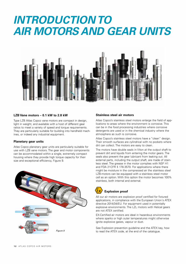
LZB Vane motors – 0.1 kW to 2.8 kW
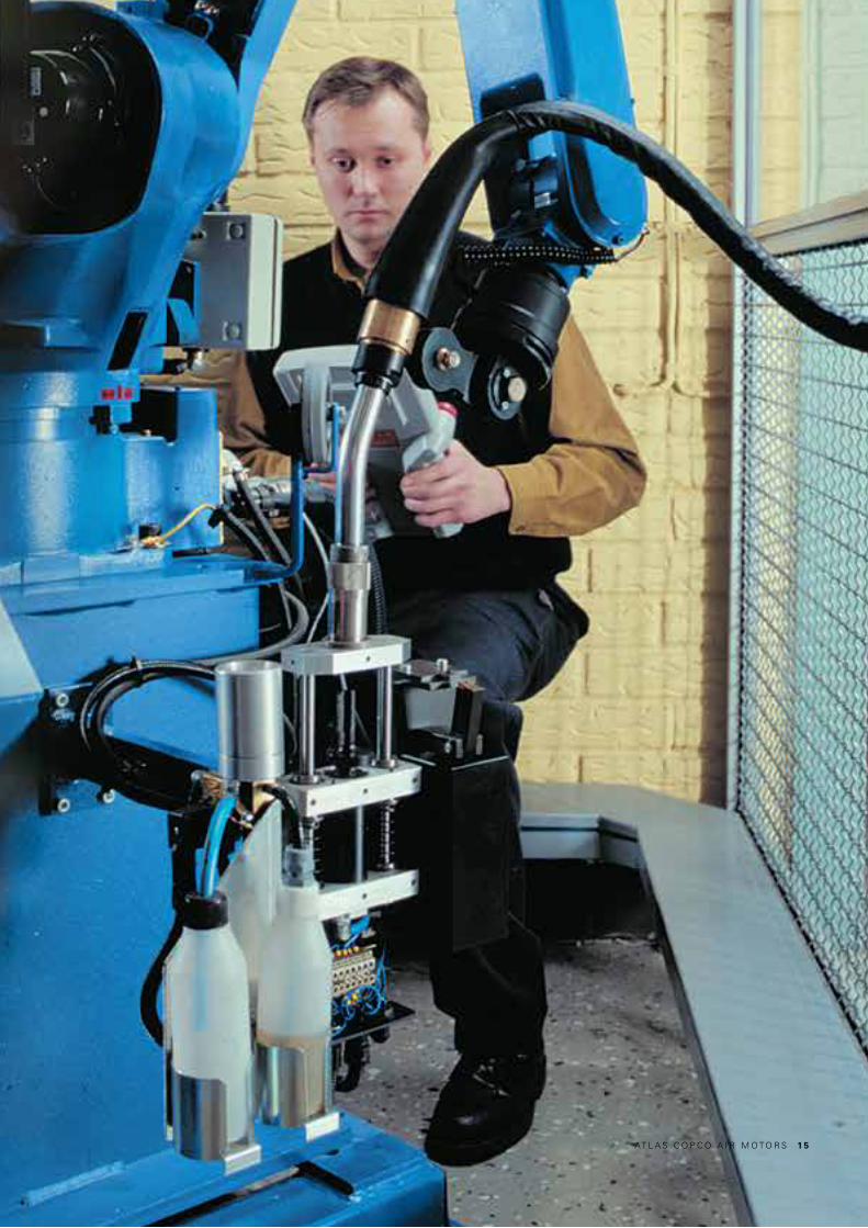
Type LZB Atlas Copco vane motors are compact in design, light in weight, and available with a host of different gear ratios to meet a variety of speed and torque requirements. They are particularly suitable for building into handheld mach-ines, or indeed any industrial equipment.
Planetary gear units
Atlas Copco planetary gear units are particularly suitable for use with LZB vane motors. The gear and motor components can be accommodated within a single, extremely compact housing where they provide high torque capacity for their size and exceptional efficiency, Figure 9.
Stainless steel air motors
Atlas Copco’s stainless steel motors enlarge the field of app-lications to areas where the environment is corrosive. This can be in the food processing industries where corrosive detergents are used or in the chemical industry where the atmosphere as such is corrosive.
Atlas Copco’s stainless steel motors have a “clean“ design. Their smooth surfaces are cylindrical with no pockets where dirt can collect. The motors are easy to clean.
The motors have double seals in Viton at the output shaft toprevent dirt and liquids from entering the motor gears. The seals also prevent the gear lubricant from leaking out. All external parts, including the output shaft, are made of stain-less steel. The grease in the motor complies with NSF H1 and FDA 21CFR § 178.3570. For applications where there might be moisture in the compressed air the stainless steel LZB-motors can be equipped with a stainless steel motor cell as an option. With this option the motor becomes 100% stainless, both internal and external.
Explosion proof
All our air motors are explosion proof certified for fixtured applications, in compliance with the European Union´s ATEX directive 2014/34/EU. For equipment used in potentially explosive environments. The LZL motors with Helical gears are not ATEX certified.
EX-Certified air motors are ideal in hazardous environments where sparks or high outer temperatures might otherwise ignite explosive gases, vapour or dust.
See Explosion prevention guideline and the ATEX key, how to read the ATEX code, at the end of the catalogue.
1 2 AT L A S C O P C O A I R M O T O R S
Lubrication free air motors
Atlas Copco’s lubrication free air motors are equipped with low-friction vanes, sealed bearings and vented cylinder plates. Since they release no lubricants into the air, they offer a via-ble drive solution for sensitive processes and hygienic envi-ronments where oil contamination would be at best a pro-blem and, at worst, a catastrophe. Both lubrication free vanes and lubricated vanes are available as kits for replacement or conversion.
Silicon freeAll the air motors are 100% silicon free. For app-lications handling paint, this is an absolute must as the presence of silicone can cause big problems.
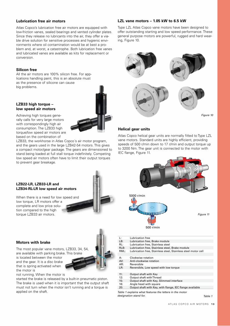
LZB33 high torque –low speed air motors
Achieving high torques gene-rally calls for very large motors with correspondingly high air consumption. The LZB33 high torque/low speed air motors are based on the combination of LZB33, the workhorse in Atlas Copco´s air motor program, and the gears used in the large LZB42-54 motors. This gives a compact motor/gear package. The gears are dimensioned to stand being loaded at full stall torque indefinitely. Competing low speed air motors often have to limit their output torques to prevent gear breakage.
LZB22-LR, LZB33-LR and LZB34-RL-LR low speed air motors
When there is a need for low speed and low torque, LR motors offer a complete and low price solu-tion compared to the high torque LZB33 air motors.
Motors with brake
The most popular vane motors, LZB33, 34, 54, are available with parking brake. This brake is located between the motor and the gear. It is a disc brake that is spring activated when the motor isnot running. When the motor is started the brake is released by a built-in pneumatic piston. The brake is used when it is important that the output shaft must not turn when the motor isn’t running and a torque is applied on the shaft.
5000 r/min
500 r/min
Helical gear units
Atlas Copco helical gear units are normally fitted to Type LZL vane motors. Standard units are highly efficient, providing speeds of 500 r/min down to 17 r/min and output torque up to 3200 Nm. The gear unit is connected to the motor with IEC flange, Figure 11.
LZL vane motors – 1.05 kW to 6.5 kW
Type LZL Atlas Copco vane motors have been designed to offer outstanding starting and low speed performance. These general purpose motors are powerful, rugged and hard wear-ing, Figure 10.
Figure 10
Figure 11
Table 1
L: Lubrication freeLB: Lubrication free, Brake moduleRL: Lubrication free, Stainless steelRLB: Lubrication free, Stainless steel, Brake moduleRML: Lubrication free, Stainless steel, Stainless steel motor cell
A: Clockwise rotationAV: Anti-clockwise rotationAR: ReversibleLR: Reversible, Low speed with low torque
11: Output shaft with Key12: Output shaft with Thread15: Output shaft with Key, Slimmed interface16: Angle head with square 20: Output shaft with Key, with flange, IEC flange available
Table 1 explains what features the letters in the motordesignation stand for.
AT L A S C O P C O A I R M O T O R S 1 3

LZBVANE MOTORS
1 4 AT L A S C O P C O A I R M O T O R S
AT L A S C O P C O A I R M O T O R S 1 5

Cylindric
shaft
Threaded
shaft
Fr
Fa Fa
FrA
FaN
4000
3000
2000
1000
7000600050004000300020001000
FrN
Curve hCurve gCurve fCurve e
A = 20 mmA = 15 mmA = 20 mmA = 15 mm
FaN
2000
1500
1000
500
200015001000500
FrN
Curve dCurve cCurve bCurve a
A = 20 mmA = 15 mmA = 9 mmA = 8 mm
Coversion factor1N = 0.225 lbf
Figure 14
Figure 13
Cylindric
shaft
Threaded
shaft
Fr
Fa Fa
FrA
FaN
3500
3000
2500
2000
1500
1000
500
50004000300020001000
FrN
Curve eCurve g
500 1500 2500 3500 4500
450
Curve aCurve bCurve c
NFr
NFa
400
350
300
250
200
150
100
50
0500 1000 1500 2000 2500
LZB VANE MOTORSIntroduction
Figure 12
LZB vane motors are designed to provide high performance and high standards of reliability. They are characterized by high power output and small physical size, Figure 12.
The design of the motor is long and slim. This gives a num-ber of advantages, such as high power-to-volume ratio, low air consumption and long vane life. All motors utilize five vanes, which are supplied with vane air, to ensure excellent starting and low speed performance. Multi-step planetary gears are used to meet the torque and speed requirements of the application, offering high efficiency with compact dimensions.
Shaft loading
The maximum allowable loads on a given motor´s output shaft are illustrated in Figures 13, 14. The relevant load curve code for a motor is stated in the data tables for each speci-fic motor designation, under the ”Shaft load code” column. These values have been calculated for shaft and bearing working lives of 10 million turns. To achieve a working life of 100 million turns, the loading factor must be halved.
1 6 AT L A S C O P C O A I R M O T O R S

Hose dimensions
Information on hose dimensions recommended for use with type LZB air motors is detailed in table below. These dimensions are valid for hose lengths up to 3 m. If lengths above that are used, choose a one size larger hose.
Figure 17
Figure 15
Foot
Flange
Clockwise rotation
Anti-clockwiserotation
Figure 16
LZ
B V
AN
E M
OT
OR
S
Motor size Rotation
Inletconnec-
tionthread
BSP
Inletconnection
thread
NPTF
Inlethose*
mm
Inletrecomended
nipple connection
Ordering No.
Inletnipple*
diameter
mm
Outletconnection
thread
BSP
Outlethose*
mm
Outletrecomended
nipple connection
Ordering No.
Outletnipple*
diameter
mmLZB14 A, AV, AR 1/8 - 8 9000 0240 00 5.0 1/8 8 9000 0240 00 5.0LZB22 A, AV 1/8 - 8 9000 0240 00 5.0 1/4 10 9000 0247 00 8.0LZB22 AR, LR 1/8 - 8 9000 0240 00 5.0 1/8 8 9000 0240 00 5.0LZB33, LZB34 A, AV, AR, LR 1/4 - 10 9000 0247 00 8.0 1/4 10 9000 0247 00 8.0LZB42 A, AR 1/4 - 10 9000 0247 00 8.0 1/2 16 9000 0244 00 13.4LZB46 A, AV, AR 1/4 - 10 9000 0247 00 8.0 1/2 16 9000 0244 00 13.4LZB54 A, AV, AR 3/8 - 13 9000 0248 00 9.3 1/2 16 9000 0244 00 13.4LZB66 A, AR 3/8 - 13 9000 0248 00 9.3 3/4 20 9000 0245 00 17LZB77 A, AR - 1/2"-14 16 9000 0244 01 13.4 - - - -LZB77 A, AR 1/2** - 16 9000 0244 00 13.4 - - - -* Recommended minimum inner diameter (for reversible motors, the same size should be used on both in-/outlet) ** Alternative connection thread BSP 1/2" delivered with the product
Hose size up to 3 m length
ConnectionNon-reversible motorWhen the compressed air supply is connected to the inlet, the direction of rotation will be as shown in Figure 16. If the exhaust air is to be piped away, a hose should be connected to the exhaust outlet. (EXH).
Reversible motorThe compressed air supply should be connected to the inlet that gives the desired direction of rotation, Figure 17. The inlet not in use functions as an additional outlet: it must not be plugged.
Clockwise rotation
Anti-clockwiserotation
Mounting
Type LZB vane motors may be mounted in any position. To facilitate this, flange and foot mounting are available for each motor, Figure 15.
AT L A S C O P C O A I R M O T O R S 1 7

VANE MOTORS LZB14-LLubrication free0.11 – 0.16 kW0.15 – 0.21 hpEX certification valid for fixture mounted use only with a maximum surrounding temperature of +40°C (104°F).
For optional vanes and accessories see chapter Accessories.
Data at air pressure 6.3 bar (91 psi)
ModelLubrication free
Maxoutput
kW hp
Speedat maxoutput
r/min
Torqueat maxoutput
Nm lb-ft
Minstarting torque
Nm lb-ft
Stalltorque
Nm lb-ft
Free speed
r/min
Airconsump-tion at max
output
l/s cfm
Weight
kg lb
Shaft loadingcode 1) ATEX code Ordering No.
Clockwise rotation (Keyed shaft)LZB14-L-A190-11 0.16 0.21 9100 0.17 0.13 0.29 0.21 0.34 0.25 19500 4.0 8.5 0.30 0.66 a Ex II 2GD c T4 IIC T110°C 8411 0113 00LZB14-L-A048-11 0.16 0.21 2200 0.7 0.52 1.23 0.91 1.4 1.03 4800 4.0 8.5 0.30 0.66 a Ex II 2GD c T6 IIC T85°C 8411 0113 18LZB14-L-A029-11 0.16 0.21 1330 1.15 0.85 2 1.48 2.3 1.7 2900 4.0 8.5 0.30 0.66 a Ex II 2GD c T6 IIC T85°C 8411 0113 26LZB14-L-A012-11 0.16 0.21 530 2.9 2.1 5.1 3.8 5.8 4.28 1140 4.0 8.5 0.33 0.73 a Ex II 2GD c T6 IIC T85°C 8411 0113 34LZB14-L-A007-11 0.16 0.21 320 4.8 3.5 8.5 6.27 9.6 7.1 700 4.0 8.5 0.33 0.73 a Ex II 2GD c T6 IIC T85°C 8411 0113 42Clockwise rotation (Threaded shaft) LZB14-L-A190-12 0.16 0.21 9100 0.17 0.13 0.29 0.21 0.34 0.25 19500 4.0 8.5 0.30 0.66 a Ex II 2GD c T4 IIC T110°C 8411 0114 09LZB14-L-A048-12 0.16 0.21 2200 0.7 0.52 1.23 0.91 1.4 1.03 4800 4.0 8.5 0.30 0.66 a Ex II 2GD c T6 IIC T85°C 8411 0114 17LZB14-L-A029-12 0.16 0.21 1330 1.15 0.85 2.0 1.48 2.3 1.7 2900 4.0 8.5 0.30 0.66 a Ex II 2GD c T6 IIC T85°C 8411 0114 25LZB14-L-A012-12 0.16 0.21 530 2.9 2.1 5.1 3.8 5.8 4.28 1140 4.0 8.5 0.33 0.73 a Ex II 2GD c T6 IIC T85°C 8411 0114 33LZB14-L-A007-12 0.16 0.21 320 4.8 3.5 8.5 6.27 9.6 7.1 700 4.0 8.5 0.33 0.73 a Ex II 2GD c T6 IIC T85°C 8411 0114 41Anti-clockwise rotation (Keyed shaft) LZB14-L-AV190-11 0.16 0.21 9100 0.17 0.13 0.23 0.17 0.34 0.25 19500 4.0 8.5 0.30 0.66 a Ex II 2GD c T4 IIC T110°C 8411 0117 06LZB14-L-AV048-11 0.16 0.21 2200 0.7 0.52 0.99 0.73 1.4 1.03 4800 4.0 8.5 0.30 0.66 a Ex II 2GD c T6 IIC T85°C 8411 0117 14LZB14-L-AV029-11 0.16 0.21 1330 1.15 0.85 1.63 1.2 2.3 1.7 2900 4.0 8.5 0.30 0.66 a Ex II 2GD c T6 IIC T85°C 8411 0117 22LZB14-L-AV012-11 0.16 0.21 530 2.9 2.1 4.1 3.0 5.8 4.3 1140 4.0 8.5 0.33 0.73 a Ex II 2GD c T6 IIC T85°C 8411 0117 30LZB14-L-AV007-11 0.16 0.21 320 4.8 3.5 6.8 5.0 9.6 7.1 700 4.0 8.5 0.33 0.73 a Ex II 2GD c T6 IIC T85°C 8411 0117 48Reversible (Keyed shaft) LZB14-L-AR140-11 0.11 0.15 7000 0.15 0.11 0.24 0.18 0.3 0.22 13000 3.6 7.6 0.30 0.66 a Ex II 2GD c T4 IIC T110°C 8411 0115 08LZB14-L-AR034-11 0.11 0.15 1690 0.62 0.46 1.01 0.74 1.24 0.91 3400 3.6 7.6 0.30 0.66 a Ex II 2GD c T6 IIC T85°C 8411 0115 16LZB14-L-AR020-11 0.11 0.15 1020 1.03 0.76 1.67 1.23 2.1 1.5 2000 3.6 7.6 0.30 0.66 a Ex II 2GD c T6 IIC T85°C 8411 0115 24LZB14-L-AR008-11 0.11 0.15 410 2.6 1.92 4.2 3.1 5.2 3.8 800 3.6 7.6 0.33 0.73 a Ex II 2GD c T6 IIC T85°C 8411 0115 32LZB14-L-AR005-11 0.11 0.15 250 4.3 3.2 6.9 5.1 8.6 6.3 490 3.6 7.6 0.33 0.73 a Ex II 2GD c T6 IIC T85°C 8411 0115 401) For Shaft loading curves, see page 16. NOTE: - If running motors with 100% dry air and no lubrication, performance can be reduced with 5-15% at max output. - To optimize life time for a lubrication free motor, use lubricated air if the application allows it.
27.9
7.9
BSP 1/8”
17
12 Ø27
130.5*
111*
6.8
A/F
23
2 h
7Ø6
h7
22
52
123*
111*9.5
5/16
” -2
4 U
NF
6.86.8
A/F 25
7.9
3.95
BSP 1/8”
M5
28.2
R13.5
29.5 ø
30h
7
21
2
560
15.5ø5.5
3030
80
Clockwise/Anti-clockwise
Reversible
FlangeOrdering No. 4430 0165 85
Optional mountings
FootOrdering No. 4430 0189 80
*) +9.8 mm for LZB14 A012, A007, AR008, AR005,AV012, AV007
Keyed shaft (-11) Threaded shaft (-12)
Dimensions (mm) Conversion factor 1 mm = 0.04 inch
1 8 AT L A S C O P C O A I R M O T O R S

LZ
B V
AN
E M
OT
OR
S
VANE MOTORS LZB14-RLStainless steel and lubrication free0.11 – 0.16 kW0.15 – 0.21 hpMaterial in parts:
• Back head and front part stainless steel: ISO 683/XIII Type 17, SS 14 2346, DIN 17440 X12CrNiS188
• Outgoing shaft and casing/gear rim stainless steel: ISO 683/XIII Type 9b, SS 14 2321, DIN 17440 X22CrNi17
• 100% Silicon free
• Grease that conforms to Food Grade regulations
EX certification valid for fixture mounted use only with a maximum surrounding temperature of +40°C (104°F).
ModelLubrication free
Maxoutput
kW hp
Speedat maxoutput
r/min
Torqueat maxoutput
Nm lb-ft
Minstarting torque
Nm lb-ft
Stalltorque
Nm lb-ft
Free speed
r/min
Airconsump-tion at max
outputl/s cfm
Weight
kg lb
Shaft loadingcode 1) ATEX code Ordering No.
Clockwise rotation (Keyed shaft)LZB14-RL-A190-11 0.16 0.21 9100 0.17 0.13 0.29 0.21 0.34 0.25 19500 4.0 8.5 0.37 0.82 a Ex II 2GD c T4 IIC T110°C 8411 0122 09LZB14-RL-A048-11 0.16 0.21 2200 0.70 0.52 1.23 0.91 1.4 1.03 4800 4.0 8.5 0.37 0.82 a Ex II 2GD c T6 IIC T85°C 8411 0122 17LZB14-RL-A029-11 0.16 0.21 1330 1.15 0.85 2.0 1.48 2.3 1.7 2900 4.0 8.5 0.37 0.82 a Ex II 2GD c T6 IIC T85°C 8411 0122 25LZB14-RL-A012-11 0.16 0.21 530 2.9 2.1 5.1 3.8 5.8 4.3 1140 4.0 8.5 0.40 0.88 a Ex II 2GD c T6 IIC T85°C 8411 0122 33LZB14-RL-A007-11 0.16 0.21 320 4.8 3.5 8.5 6.3 9.6 7.1 700 4.0 8.5 0.40 0.88 a Ex II 2GD c T6 IIC T85°C 8411 0122 41Reversible (Keyed shaft)LZB14-RL-AR140-11 0.11 0.15 7000 0.15 0.11 0.24 0.18 0.3 0.22 13000 3.6 7.6 0.37 0.82 a Ex II 2GD c T4 IIC T110°C 8411 0122 58LZB14-RL-AR034-11 0.11 0.15 1690 0.62 0.46 1.01 0.74 1.24 0.91 3400 3.6 7.6 0.37 0.82 a Ex II 2GD c T6 IIC T85°C 8411 0122 66LZB14-RL-AR020-11 0.11 0.15 1020 1.03 0.76 1.67 1.23 2.1 1.5 2000 3.6 7.6 0.37 0.82 a Ex II 2GD c T6 IIC T85°C 8411 0122 74LZB14-RL-AR008-11 0.11 0.15 410 2.6 1.92 4.2 3.1 5.2 3.8 800 3.6 7.6 0.40 0.88 a Ex II 2GD c T6 IIC T85°C 8411 0122 82LZB14-RL-AR005-11 0.11 0.15 250 4.3 3.2 6.9 5.1 8.6 6.3 490 3.6 7.6 0.40 0.88 a Ex II 2GD c T6 IIC T85°C 8411 0122 901) For Shaft loading curves, see page 16. NOTE: - If running motors with 100% dry air and no lubrication, performance can be reduced with 5-15% at max output. - To optimize life time for a lubrication free motor, use lubricated air if the application allows it.
Data at air pressure 6.3 bar (91 psi)
7.9
7.9
BSP 1/8”
22
52
17.1
2
12 Ø27
134*
114.2*
6.8
A/F
23
2 h
7Ø6
h7
M5
28.2
R13.5
29.5 ø
30h
7
21.8
2
5
72
3030
ø5.5
15.560
6.86.8
A/F 25
7.9
3.95
BSP 1/8”
Clockwise
Reversible
Optional mountings
FootOrdering No. 4430 0923 80
FlangeOrdering No. 4430 0922 80
Keyed shaft (-11)
Dimensions (mm)
*) +9.8 mm for LZB14-RLA012, A007, AR008, AR005
Conversion factor 1 mm = 0.04 inch
For optional stainless steel motor cell, vane kits and other accessories see chapter Accessories.
AT L A S C O P C O A I R M O T O R S 1 9

Nm LZB14-L-A190 l/s
r/min
kW0.180.160.140.120.100.080.060.040.02
0.360.320.280.240.200.160.120.080.04
54321
4000 8000 2000012000 16000
Nm LZB14-L-A048 l/s
r/min
kW0.180.160.140.120.100.080.060.040.02
1.61.41.21.00.80.60.40.2
54321
1000 2000 50003000 4000
Nm LZB14-L-A007 l/s
r/min
kW0.180.160.140.120.100.080.060.040.02
10.59.07.56.04.53.01.5
54321
100 300 700500200 400 600
Nm LZB14-L-AR140 l/s
r/min
kW0.12
0.10
0.08
0.06
0.04
0.02
0.4
0.3
0.2
0.1
5
4
3
2
1
4000 8000 12000
Nm LZB14-L-A029 l/s
r/min
kW0.180.160.140.120.100.080.060.040.02
2.42.11.81.51.20.90.60.3
54321
500 1000 25001500 2000 3000
Nm LZB14-L-A012 l/s
r/min
kW0.180.160.140.120.100.080.060.040.02
654321
54321
200 400 1200600 800 1000
Nm LZB14-L-AR034 l/s
r/min
kW0.12
0.10
0.08
0.06
0.04
0.02
1.5
1.2
0.9
0.6
0.3
5
4
3
2
1
500 100015002000250030003500
Nm LZB14-L-AR020 l/s
r/min
kW0.12
0.10
0.08
0.06
0.04
0.02
2.4
2.0
1.6
1.2
0.8
0.4
5
4
3
2
1
400 800 1200 1600 2000 2400
Nm LZB14-L-AR008 l/s
r/min
kW0.12
0.10
0.08
0.06
0.04
0.02
6
5
4
3
2
1
5
4
3
2
1
200 400 600 800 1000
Nm LZB14-L-AR005 l/s
r/min
kW0.12
0.10
0.08
0.06
0.04
0.02
9.0
7.5
6.0
4.5
3.0
1.5
5
4
3
2
1
100 200 300 400 500
LZB14-L, LZB14-RL: Performance curves at air pressure 6.3 bar (91 psi)Non-reversible (A and AV)
Conversion factors1 kW = 1.34 hp1 Nm = 0.74 Ibf - ft1 l/s = 2.1 cfm
1 hp = 0.75 kW1 Ibf-ft = 1.36 Nm1 cfm = 0.47 l/s
TorqueNmPowerkW
Maxoutput
Torqueat maxoutput
Torque
Power
Speed r/min
Air. cons.
Air cons.l/s
For information about performance curves, see page 7.
Reversible (AR)
2 0 AT L A S C O P C O A I R M O T O R S
LZ
B V
AN
E M
OT
OR
S
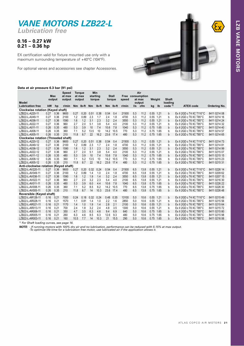
VANE MOTORS LZB22-LLubrication free0.16 – 0.27 kW0.21 – 0.36 hp
ModelLubrication free
Maxoutput
kW hp
Speedat maxoutput
r/min
Torqueat maxoutput
Nm lb-ft
Minstarting torque
Nm lb-ft
Stalltorque
Nm lb-ft
Free speed
r/min
Airconsumption
at maxoutput
l/s cfm
Weight
kg lb
Shaft loadingcode 1) ATEX code Ordering No.
Clockwise rotation (Keyed shaft)LZB22-L-A220-11 0.27 0.36 9600 0.27 0.20 0.51 0.38 0.54 0.4 21500 5.3 11.2 0.55 1.21 b Ex II 2GD c T4 IIC T110°C 8411 0214 08LZB22-L-A049-11 0.27 0.36 2100 1.2 0.89 2.3 1.7 2.4 1.8 4700 5.3 11.2 0.55 1.21 b Ex II 2GD c T6 IIC T85°C 8411 0214 16LZB22-L-A036-11 0.27 0.36 1590 1.6 1.2 3.1 2.3 3.2 2.4 3550 5.3 11.2 0.55 1.21 b Ex II 2GD c T6 IIC T85°C 8411 0214 24LZB22-L-A022-11 0.27 0.36 960 2.7 2.0 5.1 3.8 5.4 4.0 2100 5.3 11.2 0.55 1.21 b Ex II 2GD c T6 IIC T85°C 8411 0214 32LZB22-L-A011-11 0.26 0.35 480 5.3 3.9 10 7.4 10.6 7.8 1040 5.3 11.2 0.75 1.65 b Ex II 2GD c T6 IIC T85°C 8411 0214 40LZB22-L-A008-11 0.26 0.35 360 7.1 5.2 13.5 10 14.2 10.5 770 5.3 11.2 0.75 1.65 b Ex II 2GD c T6 IIC T85°C 8411 0214 57LZB22-L-A005-11 0.26 0.35 210 11.8 8.7 22 16.2 23.6 17.4 480 5.3 11.2 0.75 1.65 b Ex II 2GD c T6 IIC T85°C 8411 0214 65Clockwise rotation (Threaded shaft)LZB22-L-A220-12 0.27 0.36 9600 0.27 0.20 0.51 0.38 0.54 0.4 21500 5.3 11.2 0.55 1.21 b Ex II 2GD c T4 IIC T110°C 8411 0214 73LZB22-L-A049-12 0.27 0.36 2100 1.2 0.89 2.3 1.7 2.4 1.8 4700 5.3 11.2 0.55 1.21 b Ex II 2GD c T6 IIC T85°C 8411 0214 81LZB22-L-A036-12 0.27 0.36 1590 1.6 1.2 3.1 2.3 3.2 2.4 3550 5.3 11.2 0.55 1.21 b Ex II 2GD c T6 IIC T85°C 8411 0214 99LZB22-L-A022-12 0.27 0.36 960 2.7 2.0 5.1 3.8 5.4 4.0 2100 5.3 11.2 0.55 1.21 b Ex II 2GD c T6 IIC T85°C 8411 0215 07LZB22-L-A011-12 0.26 0.35 480 5.3 3.9 10 7.4 10.6 7.8 1040 5.3 11.2 0.75 1.65 b Ex II 2GD c T6 IIC T85°C 8411 0215 15LZB22-L-A008-12 0.26 0.35 360 7.1 5.2 13.5 10 14.2 10.5 770 5.3 11.2 0.75 1.65 b Ex II 2GD c T6 IIC T85°C 8411 0215 23LZB22-L-A005-12 0.26 0.35 210 11.8 8.7 22 16.2 23.6 17.4 480 5.3 11.2 0.75 1.65 b Ex II 2GD c T6 IIC T85°C 8411 0215 31Anti-clockwise rotation (Keyed shaft)LZB22-L-AV220-11 0.27 0.36 9600 0.27 0.20 0.32 0.24 0.54 0.4 21500 6.5 13.8 0.55 1.21 b Ex II 2GD c T4 IIC T110°C 8411 0226 14LZB22-L-AV049-11 0.27 0.36 2100 1.2 0.89 1.4 1.0 2.4 1.8 4700 6.5 13.8 0.55 1.21 b Ex II 2GD c T6 IIC T85°C 8411 0209 62LZB22-L-AV036-11 0.27 0.36 1590 1.6 1.2 1.9 1.4 3.2 2.4 3550 6.5 13.8 0.55 1.21 b Ex II 2GD c T6 IIC T85°C 8411 0207 15LZB22-L-AV022-11 0.27 0.36 960 2.7 2.0 3.2 2.3 5.4 4.0 2100 6.5 13.8 0.55 1.21 b Ex II 2GD c T6 IIC T85°C 8411 0216 30LZB22-L-AV011-11 0.26 0.35 480 5.3 3.9 6.0 4.4 10.6 7.8 1040 6.5 13.8 0.75 1.65 b Ex II 2GD c T6 IIC T85°C 8411 0226 22LZB22-L-AV008-11 0.26 0.35 360 7.1 5.2 8.5 6.2 14.2 10.5 770 6.5 13.8 0.75 1.65 b Ex II 2GD c T6 IIC T85°C 8411 0226 30LZB22-L-AV005-11 0.26 0.35 210 11.8 8.7 14 10.3 23.6 17.4 480 6.5 13.8 0.75 1.65 b Ex II 2GD c T6 IIC T85°C 8411 0226 48Reversible (Keyed shaft)LZB22-L-AR126-11 0.16 0.21 7000 0.24 0.18 0.32 0.24 0.48 0.35 13100 5.0 10.6 0.55 1.21 b Ex II 2GD c T4 IIC T110°C 8411 0215 49LZB22-L-AR028-11 0.16 0.21 1570 1.1 0.81 1.4 1.0 2.2 1.6 2850 5.0 10.6 0.55 1.21 b Ex II 2GD c T6 IIC T85°C 8411 0215 56LZB22-L-AR021-11 0.16 0.21 1170 1.4 1.0 1.9 1.4 2.8 2.1 2100 5.0 10.6 0.55 1.21 b Ex II 2GD c T6 IIC T85°C 8411 0215 64LZB22-L-AR013-11 0.16 0.21 700 2.4 1.8 3.2 2.4 4.8 3.5 1300 5.0 10.6 0.55 1.21 b Ex II 2GD c T6 IIC T85°C 8411 0215 72LZB22-L-AR006-11 0.16 0.21 350 4.7 3.5 6.3 4.6 9.4 6.9 640 5.0 10.6 0.75 1.65 b Ex II 2GD c T6 IIC T85°C 8411 0215 80LZB22-L-AR005-11 0.16 0.21 260 6.3 4.6 8.5 6.3 12.6 9.3 480 5.0 10.6 0.75 1.65 b Ex II 2GD c T6 IIC T85°C 8411 0215 98LZB22-L-AR003-11 0.16 0.21 160 10.5 7.7 14 10.3 21 15.5 290 5.0 10.6 0.75 1.65 b Ex II 2GD c T6 IIC T85°C 8411 0216 061) For Shaft loading curves, see page 16. NOTE: - If running motors with 100% dry air and no lubrication, performance can be reduced with 5-15% at max output. - To optimize life time for a lubrication free motor, use lubricated air if the application allows it.
Data at air pressure 6.3 bar (91 psi)
EX certification valid for fixture mounted use only with a maximum surrounding temperature of +40°C (104°F).
For optional vanes and accessories see chapter Accessories.
AT L A S C O P C O A I R M O T O R S 2 1
9.5
9.5
68
BSP 1/8”
A/F
31
A/F
33
Ø36
Ø10
h6
3 h7
11.2
Ø12
3
M4
16
THREAD DEPTH 12 mm
23.5
135.5*
110.9*Ø
18
3/8”
-24
UN
F
127*
111*16
11
BSP 1/4”
A/F 31
BSP 1/8”
7.7
11.4
BSP 1/8”9.5
A/F
31
7.5
5 BSP 1/4”
6
60
10
M5
50
32
37.2
15
R18
26
2
5
Ø30
h7
80
3030
18
Ø5.5
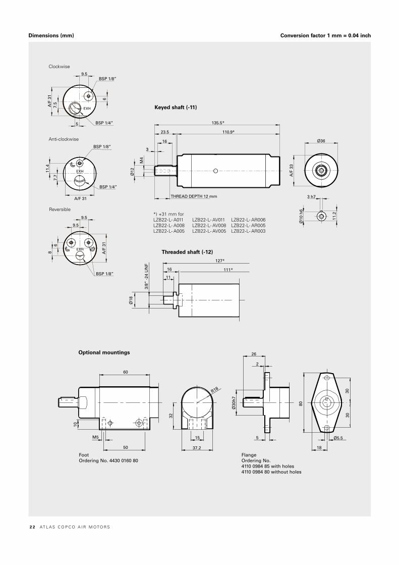
Dimensions (mm) Conversion factor 1 mm = 0.04 inch
Keyed shaft (-11)
Threaded shaft (-12)
FlangeOrdering No.4110 0984 85 with holes4110 0984 80 without holes
Optional mountings
FootOrdering No. 4430 0160 80
*) +31 mm forLZB22-L- A011 LZB22-L- AV011 LZB22-L- AR006LZB22-L- A008 LZB22-L- AV008 LZB22-L- AR005LZB22-L- A005 LZB22-L- AV005 LZB22-L- AR003
Clockwise
Reversible
Anti-clockwise
2 2 AT L A S C O P C O A I R M O T O R S

LZ
B V
AN
E M
OT
OR
S
VANE MOTORS LZB22-RLStainless steel and lubrication free0.16 – 0.27 kW0.21 – 0.36 hp
Material in parts:
• Back head, casing and front part stainless steel: ISO 683/XIII Type 17, SS 14 2346, DIN 17440 X12CrNiS188
• Outgoing shaft and gear rim stainless steel: ISO 683/XIII Type 9b, SS 14 2321, DIN 17440 X22CrNi17'
• 100% Silicon free
• Grease that conforms to Food Grade regulations
EX certification valid for fixture mounted use only with a maximum surrounding temperature of +40°C (104°F).
8
9.5
6
9.5
A/F
31
BSP 1/8”
BSP 1/4”
BSP 1/8”9.5
6
7.5
5
Ø36
139.5*
115*24.5
183
Ø12
11.2
Ø10 h6
3 h7
26.5
2
5
18
Ø5.5
72
30
Ø30
h7
32
30
15
37.2
R18
10
50
60
M5
M4
THREAD DEPTH 8 mm *) +31.2 mm forLZB22-RL- A011 LZB22-RL- AR006LZB22-RL- A008 LZB22-RL- AR005LZB22-RL- A005 LZB22-RL- AR003
Optional mounting
FootOrdering No. 4430 0862 80
Dimensions (mm) Conversion factor 1 mm = 0.04 inch
ModelLubrication free
Maxoutput
kW hp
Speedat maxoutput
r/min
Torqueat maxoutput
Nm lb-ft
Minstarting torque
Nm lb-ft
Stalltorque
Nm lb-ft
Free speed
r/min
Airconsump-tion at max
outputl/s cfm
Weight
kg lb
Shaft loadingcode 1) ATEX code Ordering No.
Clockwise rotation (Keyed shaft)LZB22-RL-A220-11 0.27 0.36 9600 0.27 0.20 0.51 0.38 0.54 0.4 19500 5.3 11.2 0.63 1.39 b Ex II 2GD c T4 IIC T110°C 8411 0219 11LZB22-RL-A049-11 0.27 0.36 2100 1.2 0.89 2.3 1.7 2.4 1.8 4700 5.3 11.2 0.63 1.39 b Ex II 2GD c T6 IIC T85°C 8411 0219 29LZB22-RL-A036-11 0.27 0.36 1590 1.6 1.2 3.1 2.3 3.2 2.4 3550 5.3 11.2 0.63 1.39 b Ex II 2GD c T6 IIC T85°C 8411 0219 37LZB22-RL-A022-11 0.27 0.36 960 2.7 2.0 5.1 3.8 5.4 4.0 2100 5.3 11.2 0.63 1.39 b Ex II 2GD c T6 IIC T85°C 8411 0219 45LZB22-RL-A011-11 0.26 0.35 480 5.3 3.9 10 7.4 10.6 7.8 1040 5.3 11.2 0.83 1.83 b Ex II 2GD c T6 IIC T85°C 8411 0219 52LZB22-RL-A008-11 0.26 0.35 360 7.1 5.2 13.5 10 14.2 10.5 770 5.3 11.2 0.83 1.83 b Ex II 2GD c T6 IIC T85°C 8411 0219 60LZB22-RL-A005-11 0.26 0.35 210 11.8 8.7 22 16.2 23.6 17.4 480 5.3 11.2 0.83 1.83 b Ex II 2GD c T6 IIC T85°C 8411 0219 78Reversible (Keyed shaft)LZB22-RL-AR126-11 0.16 0.21 7000 0.24 0.18 0.32 0.24 0.48 0.35 13100 5.0 10.6 0.63 1.39 b Ex II 2GD c T4 IIC T110°C 8411 0220 83LZB22-RL-AR028-11 0.16 0.21 1570 1.1 0.81 1.4 1.0 2.2 1.6 2850 5.0 10.6 0.63 1.39 b Ex II 2GD c T6 IIC T85°C 8411 0220 75LZB22-RL-AR021-11 0.16 0.21 1170 1.4 1.0 1.9 1.4 2.8 2.1 2100 5.0 10.6 0.63 1.39 b Ex II 2GD c T6 IIC T85°C 8411 0222 16LZB22-RL-AR013-11 0.16 0.21 700 2.4 1.8 3.2 2.4 4.8 3.5 1300 5.0 10.6 0.63 1.39 b Ex II 2GD c T6 IIC T85°C 8411 0220 67LZB22-RL-AR006-11 0.16 0.21 350 4.7 3.5 6.3 4.6 9.4 6.9 640 5.0 10.6 0.83 1.83 b Ex II 2GD c T6 IIC T85°C 8411 0220 59LZB22-RL-AR005-11 0.16 0.21 260 6.3 4.6 8.5 6.3 12.6 9.3 480 5.0 10.6 0.83 1.83 b Ex II 2GD c T6 IIC T85°C 8411 0222 08LZB22-RL-AR003-11 0.16 0.21 160 10.5 7.7 14 10.3 21 15.5 290 5.0 10.6 0.83 1.83 b Ex II 2GD c T6 IIC T85°C 8411 0220 911) For Shaft loading curves, see page 16. NOTE: - If running motors with 100% dry air and no lubrication, performance can be reduced with 5-15% at max output. - To optimize life time for a lubrication free motor, use lubricated air if the application allows it.
Keyed shaft (-11)
Data at air pressure 6.3 bar (91 psi)
Clockwise
Reversible
FlangeOrdering No. 4430 0861 80
For optional stainless steel motor cell, vane kits and otheraccessories see chapter Accessories.
AT L A S C O P C O A I R M O T O R S 2 3

LZB22-L, LZB22-RL: Performance curves at air pressure 6.3 bar (91 psi)Non-reversible (A and AV)
Nm LZB22-L-A220 l/s
r/min
kW
0.30
0.25
0.20
0.15
0.10
0.05
0.75
0.60
0.45
0.30
0.15
7.5
6.0
4.5
3.0
1.5
4000 8000 12000 16000 20000 24000
Nm LZB22-L-A049 l/s
r/min
kW
0.30
0.25
0.20
0.15
0.10
0.05
3.0
2.5
2.0
1.5
1.0
0.5
7.5
6.0
4.5
3.0
1.5
1000 2000 3000 4000 5000 r/min
Nm LZB22-L-A036 l/skW
0.30
0.25
0.20
0.15
0.10
0.05
4
3
2
1
7.5
6.0
4.5
3.0
1.5
1000 2000 40003000
r/min
Nm LZB22-L-A022 l/skW
0.30
0.25
0.20
0.15
0.10
0.05
7.5
6.0
4.5
3.0
1.5
7.5
6.0
4.5
3.0
1.5
400 800 1200 1600 2000 2400 r/minr/min
Nm LZB22-L-A011 l/skW
0.30
0.25
0.20
0.15
0.10
0.05
12
10
8
6
4
2
7.5
6.0
4.5
3.0
1.5
200 400 600 800 1000 1200
Nm LZB22-L-A008 l/s
r/min
kW
0.30
0.25
0.20
0.15
0.10
0.05
18
15
12
9
6
3
7.5
6.0
4.5
3.0
1.5
200 400 600 1000800
Nm LZB22-L-A005 l/s
r/min
kW
0.30
0.25
0.20
0.15
0.10
0.05
30
25
20
15
10
5
7.5
6.0
4.5
3.0
1.5
100 200 300 500400
Nm LZB22-L-AR126 l/s
r/min
kW
0.180.160.140.120.100.080.060.040.02
0.450.400.350.300.250.200.150.100.05
654321
4000 120008000
Nm LZB22-L-AR028 l/s
r/min
kW
0.180.160.140.120.100.080.060.040.02
2.11.81.51.20.90.60.3
654321
500 1000 1500 2000 2500 3000 3500 400 800 1200 1600 2000
Nm LZB22-L-AR021 l/s
r/min
kW
0.180.160.140.120.100.080.060.040.02
2.72.42.11.81.51.20.90.60.3
654321
2400
Nm LZB22-L-AR013 l/s
r/min
kW
0.180.160.140.120.100.080.060.040.02
4.54.03.53.02.52.01.51.00.5
654321
200 400 600 800 1000 1200 1400
Nm LZB22-L-AR006 l/s
r/min
kW
0.180.160.140.120.100.080.060.040.02
987654321
654321
100 200 300 400 500 600 700
Nm LZB22-L-AR005 l/s
r/min
kW
0.180.160.140.120.100.080.060.040.02
12.010.5
9.07.56.04.53.01.5
654321
100 200 300 400 500 600
Nm LZB22-L-AR003 l/s
r/min
kW
0.180.160.140.120.100.080.060.040.02
21181512
963
654321
50 100 150 200 250 300 350
LZB22-L, LZB22-RL: Performance curves at air pressure 6.3 bar (91 psi)Reversible (AR)
Nm LZB22-L-A220 l/s
r/min
kW
0.30
0.25
0.20
0.15
0.10
0.05
0.75
0.60
0.45
0.30
0.15
7.5
6.0
4.5
3.0
1.5
4000 8000 12000 16000 20000 24000
Nm LZB22-L-A049 l/s
r/min
kW
0.30
0.25
0.20
0.15
0.10
0.05
3.0
2.5
2.0
1.5
1.0
0.5
7.5
6.0
4.5
3.0
1.5
1000 2000 3000 4000 5000 r/min
Nm LZB22-L-A036 l/skW
0.30
0.25
0.20
0.15
0.10
0.05
4
3
2
1
7.5
6.0
4.5
3.0
1.5
1000 2000 40003000
r/min
Nm LZB22-L-A022 l/skW
0.30
0.25
0.20
0.15
0.10
0.05
7.5
6.0
4.5
3.0
1.5
7.5
6.0
4.5
3.0
1.5
400 800 1200 1600 2000 2400 r/minr/min
Nm LZB22-L-A011 l/skW
0.30
0.25
0.20
0.15
0.10
0.05
12
10
8
6
4
2
7.5
6.0
4.5
3.0
1.5
200 400 600 800 1000 1200
Nm LZB22-L-A008 l/s
r/min
kW
0.30
0.25
0.20
0.15
0.10
0.05
18
15
12
9
6
3
7.5
6.0
4.5
3.0
1.5
200 400 600 1000800
Nm LZB22-L-A005 l/s
r/min
kW
0.30
0.25
0.20
0.15
0.10
0.05
30
25
20
15
10
5
7.5
6.0
4.5
3.0
1.5
100 200 300 500400
Nm LZB22-L-AR126 l/s
r/min
kW
0.180.160.140.120.100.080.060.040.02
0.450.400.350.300.250.200.150.100.05
654321
4000 120008000
Nm LZB22-L-AR028 l/s
r/min
kW
0.180.160.140.120.100.080.060.040.02
2.11.81.51.20.90.60.3
654321
500 1000 1500 2000 2500 3000 3500 400 800 1200 1600 2000
Nm LZB22-L-AR021 l/s
r/min
kW
0.180.160.140.120.100.080.060.040.02
2.72.42.11.81.51.20.90.60.3
654321
2400
Nm LZB22-L-AR013 l/s
r/min
kW
0.180.160.140.120.100.080.060.040.02
4.54.03.53.02.52.01.51.00.5
654321
200 400 600 800 1000 1200 1400
Nm LZB22-L-AR006 l/s
r/min
kW
0.180.160.140.120.100.080.060.040.02
987654321
654321
100 200 300 400 500 600 700
Nm LZB22-L-AR005 l/s
r/min
kW
0.180.160.140.120.100.080.060.040.02
12.010.5
9.07.56.04.53.01.5
654321
100 200 300 400 500 600
Nm LZB22-L-AR003 l/s
r/min
kW
0.180.160.140.120.100.080.060.040.02
21181512
963
654321
50 100 150 200 250 300 350
Conversion factors1 kW = 1.34 hp1 Nm = 0.74 Ibf - ft1 l/s = 2.1 cfm
1 hp = 0.75 kW1 Ibf-ft = 1.36 Nm1 cfm = 0.47 l/s
TorqueNmPowerkW
Maxoutput
Torqueat maxoutput
Torque
Power
Speed r/min
Air. cons.
Air cons.l/s
For information about performance curves, see page 7.
2 4 AT L A S C O P C O A I R M O T O R S

LZ
B V
AN
E M
OT
OR
S
VANE MOTORS LZB22-L-LRLow speed, low torque, lubrication free and reversibleLZB22-RL-LRStainless steel, low speed, low torque, lubrication free and reversible
Model Lubrication free
Free speed
r/min
Airconsumption at
free speed
l/s cfm
Weight
kg lbShaft loading
code 1) ATEX code Ordering No.LZB22-L-LR100-11 110 5.8 12.3 0.95 2.09 b Ex II 2GD c T6 IIC T85°C 8411 0216 22LZB22-L-LR5-11 5 5.8 12.3 1.35 3.0 b Ex II 2GD c T6 IIC T85°C 8411 0216 14Stainless steel, Lubrication freeLZB22-RL-LR100-11 110 5.8 12.3 1.03 2.27 b Ex II 2GD c T6 IIC T85°C 8411 0222 40LZB22-RL-LR5-11 5 5.8 12.3 1.43 3.15 b Ex II 2GD c T6 IIC T85°C 8411 0222 571) For Shaft loading curves, see page 16. NOTE: - If running motors with 100% dry air and no lubrication, performance can be reduced with 10-20% at free speed. - To optimize life time for a lubrication free motor, use lubricated air if the application allows it.
Data at air pressure 6.3 bar (91 psi)
Nm LZB22-L -LR100
r/min
kW
60
50
40
30
20
10
0
0.18
0.16
0.14
0.12
0.10
0.08
0.06
0.04
0.02
00 20 40 120 1401008060
Limit
Nm LZB22-L-LR5
r/min
kW
50
45
40
35
30
25
20
15
10
5
0
0.020
0.015
0.010
0.005
05.75.6
Limit
For optional stainless steel motor cell, vane kits and otheraccessories see Chapter accessories.
Maximum permitted torque 9 Nm (6.6 lbf∙ft)Within their working range these motors have a very steep torque curve. Speed and air consumption are relatively constant regard-less of the load.
Stainless steel version:
• 100% Silicon free
• Grease that conforms to Food Grade regulations
EX certification valid for fixture mounted use only with a maximum surrounding temperature of +40°C (104°F).
AT L A S C O P C O A I R M O T O R S 2 5
8
9.5
6
9.5
A/F
31
Ø12
M4
3
23.5
16
THREAD DEPTH 12mm
198.5*
172.9*
11.2
BSP 1/8”
3 h7
Ø10
h6
A/F
33
Ø36
60
10
M5
50
32
37.2
15
R18
26
2
5Ø
30h
7
80
3030
18
Ø5.5
26.5
2
5
18
Ø5.5
72
30
Ø30
h7
32
30
15
37.2
R18
10
50
60
M5
8
9.5
6
9.5
A/F
31
Ø12
3
24.5
18
202.1*
177.5*
11.2
BSP 1/8”
3 h7Ø
10 h
6
A/F
33
Ø36
THREAD DEPTH 8mm
M4
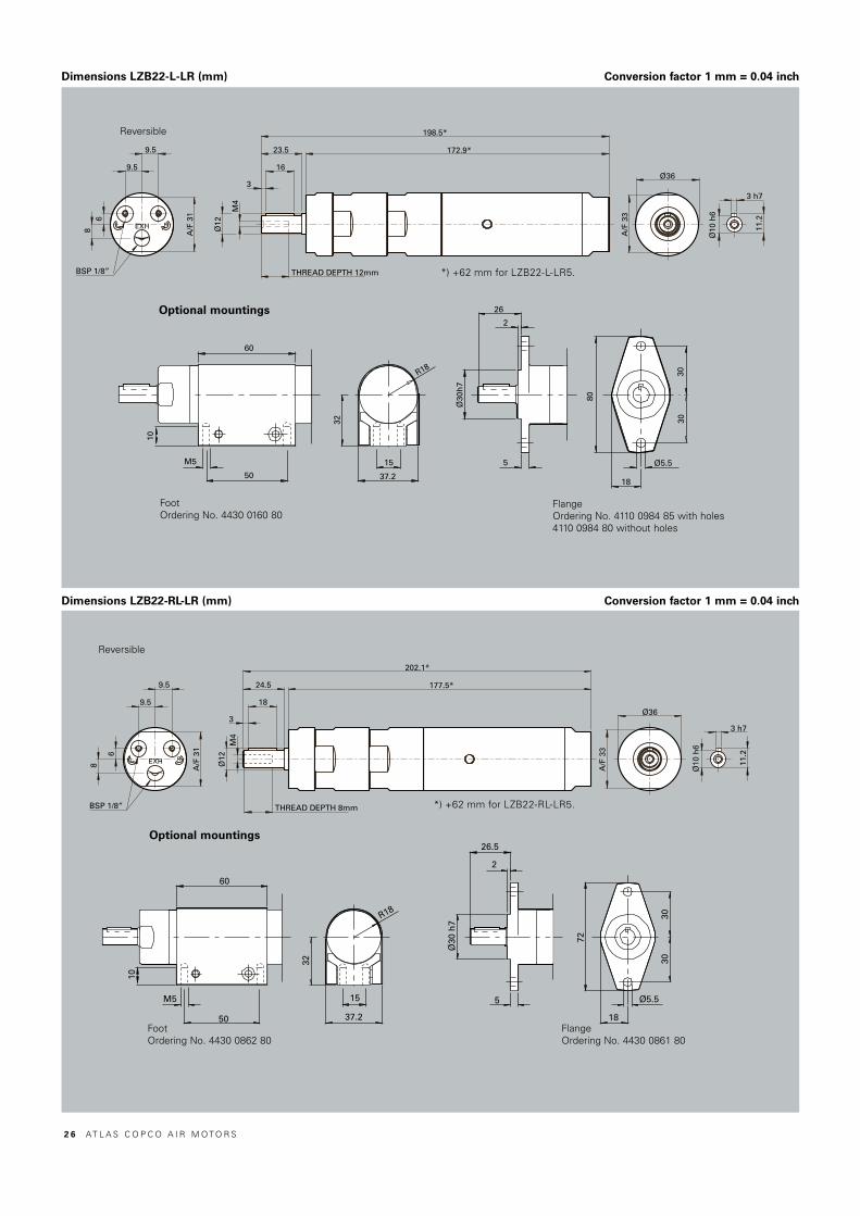
Dimensions LZB22-L-LR (mm)
Optional mountings
FootOrdering No. 4430 0160 80
Reversible
FlangeOrdering No. 4110 0984 85 with holes4110 0984 80 without holes
*) +62 mm for LZB22-L-LR5.
8
9.5
6
9.5A
/F 3
1
Ø12
M4
3
23.5
16
THREAD DEPTH 12mm
198.5*
172.9*
11.2
BSP 1/8”
3 h7
Ø10
h6
A/F
33
Ø36
60
10
M5
50
32
37.2
15
R18
26
2
5
Ø30
h7
80
3030
18
Ø5.5
26.5
2
5
18
Ø5.5
72
30
Ø30
h7
32
30
15
37.2
R18
10
50
60
M5
8
9.5
6
9.5
A/F
31
Ø12
3
24.5
18
202.1*
177.5*
11.2
BSP 1/8”
3 h7
Ø10
h6
A/F
33
Ø36
THREAD DEPTH 8mm
M4
Optional mountings
FootOrdering No. 4430 0862 80
FlangeOrdering No. 4430 0861 80
*) +62 mm for LZB22-RL-LR5.
Reversible
Dimensions LZB22-RL-LR (mm) Conversion factor 1 mm = 0.04 inch
Conversion factor 1 mm = 0.04 inch
2 6 AT L A S C O P C O A I R M O T O R S

LZ
B V
AN
E M
OT
OR
S
VANE MOTORS LZB33-LLubrication free 0.24 – 0.39 kW0.32 – 0.52 hpEX certification valid for fixture mounted use only with a maximum surroundingtemperature of +40°C (104°F).
For optional vanes and accessories see Accessories chapter
ModelLubrication free
Maxoutput
kW hp
Speedat maxoutput
r/min
Torqueat maxoutput
Nm lb-ft
Minstartingtorque
Nm lb-ft
Stalltorque
Nm lb-ft
Free speed
r/min
Airconsump-tion at max
outputl/s cfm
Weight
kg lb
Shaft lo-
adingcode 1) ATEX code Ordering No.
Clockwise rotation (Keyed shaft)LZB33-L-A210-11 0.39 0.52 9400 0.4 0.3 0.76 0.56 0.8 0.59 19000 8.1 17.2 0.75 1.65 c Ex II 2GD c T4 IIC T110°C 8411 0306 07LZB33-L-A060-11 0.39 0.52 2600 1.4 1.0 2.7 2.0 2.8 2.1 5350 8.1 17.2 0.75 1.65 c Ex II 2GD c T6 IIC T85°C 8411 0306 15LZB33-L-A033-11 0.39 0.52 1450 2.6 1.9 4.9 3.6 5.2 3.8 3000 8.1 17.2 0.75 1.65 c Ex II 2GD c T6 IIC T85°C 8411 0306 23LZB33-L-A026-11 0.39 0.52 1170 3.2 2.4 6.1 4.5 6.4 4.7 2400 8.1 17.2 0.75 1.65 c Ex II 2GD c T6 IIC T85°C 8411 0306 31LZB33-L-A013-11 0.38 0.51 580 6.4 4.7 12 8.9 12.8 9.4 1180 8.1 17.2 1.02 2.25 c Ex II 2GD c T6 IIC T85°C 8411 0306 49LZB33-L-A007-11 0.38 0.51 320 11.5 8.5 21 15.5 23 17 650 8.1 17.2 1.02 2.25 c Ex II 2GD c T6 IIC T85°C 8411 0306 56LZB33-L-A005-11 0.38 0.51 260 14.2 10.5 26 19.2 28 21 520 8.1 17.2 1.02 2.25 c Ex II 2GD c T6 IIC T85°C 8411 0306 64LZB33-L-A0030-112) 0.37 0.50 160 22.3 16.4 40 30 45 33 340 8.1 17.2 1.5 3.31 d Ex II 2GD c T6 IIC T85°C 8411 0306 72Clockwise rotation (Threaded shaft)LZB33-L-A210-12 0.39 0.52 9400 0.4 0.3 0.76 0.56 0.8 0.59 19000 8.1 17.2 0.75 1.65 c Ex II 2GD c T4 IIC T110°C 8411 0306 80LZB33-L-A060-12 0.39 0.52 2600 1.4 1.0 2.7 2.0 2.8 2.1 5350 8.1 17.2 0.75 1.65 c Ex II 2GD c T6 IIC T85°C 8411 0306 98LZB33-L-A033-12 0.39 0.52 1450 2.6 1.9 4.9 3.6 5.2 3.8 3000 8.1 17.2 0.75 1.65 c Ex II 2GD c T6 IIC T85°C 8411 0307 06LZB33-L-A026-12 0.39 0.52 1170 3.2 2.4 6.1 4.5 6.4 4.7 2400 8.1 17.2 0.75 1.65 c Ex II 2GD c T6 IIC T85°C 8411 0307 14LZB33-L-A013-12 0.38 0.51 580 6.4 4.7 12 8.9 12.8 9.4 1180 8.1 17.2 1.02 2.25 c Ex II 2GD c T6 IIC T85°C 8411 0307 22LZB33-L-A007-12 0.38 0.51 320 11.5 8.5 21 15.5 23 17 650 8.1 17.2 1.02 2.25 c Ex II 2GD c T6 IIC T85°C 8411 0307 30LZB33-L-A005-12 0.38 0.51 260 14.2 10.5 26 19.2 28 21 520 8.1 17.2 1.02 2.25 c Ex II 2GD c T6 IIC T85°C 8411 0307 48Anti-clockwise rotation (Keyed shaft)LZB33-L-AV210-11 0.39 0.52 9400 0.4 0.3 0.69 0.51 0.8 0.59 19000 9.5 20.2 0.75 1.65 c Ex II 2GD c T4 IIC T110°C 8411 0352 42LZB33-L-AV060-11 0.39 0.52 2600 1.4 1.0 2.4 1.8 2.8 2.1 5350 9.5 20.2 0.75 1.65 c Ex II 2GD c T6 IIC T85°C 8411 0352 59LZB33-L-AV033-11 0.39 0.52 1450 2.6 1.9 4.4 3.2 5.2 3.8 3000 9.5 20.2 0.75 1.65 c Ex II 2GD c T6 IIC T85°C 8411 0352 00LZB33-L-AV026-11 0.39 0.52 1170 3.2 2.4 5.5 4.1 6.4 4.7 2400 9.5 20.2 0.75 1.65 c Ex II 2GD c T6 IIC T85°C 8411 0345 91LZB33-L-AV013-11 0.38 0.51 580 6.4 4.7 11 8.1 12.8 9.4 1180 9.5 20.2 1.02 2.25 c Ex II 2GD c T6 IIC T85°C 8411 0336 27LZB33-L-AV007-11 0.38 0.51 320 11.5 8.5 19.5 14.4 23 17 650 9.5 20.2 1.02 2.25 c Ex II 2GD c T6 IIC T85°C 8411 0352 67LZB33-L-AV005-11 0.38 0.51 260 14.2 10.5 24 17.7 28 21 520 9.5 20.2 1.02 2.25 c Ex II 2GD c T6 IIC T85°C 8411 0336 19LZB33-L-AV0030-112) 0.37 0.50 160 22 16.2 38 28 44 32 340 9.5 20.2 1.5 3.31 d Ex II 2GD c T6 IIC T85°C 8411 0345 59Reversible (Keyed shaft)LZB33-L-AR150-11 0.25 0.34 7000 0.34 0.25 0.46 0.34 0.68 0.5 13300 7.9 16.8 0.75 1.65 c Ex II 2GD c T4 IIC T110°C 8411 0307 63LZB33-L-AR043-11 0.25 0.34 1960 1.2 0.89 1.6 1.2 2.4 1.8 3800 7.9 16.8 0.75 1.65 c Ex II 2GD c T6 IIC T85°C 8411 0307 71LZB33-L-AR024-11 0.25 0.34 1090 2.2 1.6 3.0 2.2 4.4 3.2 2000 7.9 16.8 0.75 1.65 c Ex II 2GD c T6 IIC T85°C 8411 0307 89LZB33-L-AR019-11 0.25 0.34 880 2.7 2.0 3.7 2.7 5.4 4.0 1700 7.9 16.8 0.75 1.65 c Ex II 2GD c T6 IIC T85°C 8411 0307 97LZB33-L-AR009-11 0.25 0.34 430 5.4 4.0 7.0 5.2 10.8 8.0 800 7.9 16.8 1.02 2.25 c Ex II 2GD c T6 IIC T85°C 8411 0308 05LZB33-L-AR005-11 0.25 0.34 240 9.8 7.2 12.6 9.3 19.6 14.5 450 7.9 16.8 1.02 2.25 c Ex II 2GD c T6 IIC T85°C 8411 0308 13LZB33-L-AR004-11 0.25 0.34 190 12.1 8.9 15.6 11.5 24 17.8 360 7.9 16.8 1.02 2.25 c Ex II 2GD c T6 IIC T85°C 8411 0308 21LZB33-L-AR0026-112) 0.24 0.32 120 19 14 20 14.8 38 28 230 7.9 16.8 1.5 3.31 d Ex II 2GD c T6 IIC T85°C 8411 0308 701) For Shaft loading curves, see page 16. 2) Flange is mounted and supplied with the motor.NOTE: - If running motors with 100% dry air and no lubrication, performance can be reduced with 5-15% at max output. - To optimize life time for a lubrication free motor, use lubricated air if the application allows it.
Data at air pressure 6.3 bar (91 psi)
ModelLubrication free
Maxoutput
kW hp
Speedat maxoutput
r/min
Torqueat maxoutput
Nm lb-ft
Minstartingtorque
Nm lb-ft
Stalltorque
Nm lb-ft
Free speed
r/min
Airconsump-tion at max
outputl/s cfm
Weight
kg lb
Shaft lo-
adingcode ATEX code Ordering No.
Clockwise rotation (Keyed shaft)LZB33-L-A013-20 0.38 0.51 580 6.4 4.7 12 8.9 12.8 9.4 1180 8.1 17.2 1.02 2.25 d Ex II 2GD c T6 IIC T85°C 8411 0352 75LZB33-L-A007-20 0.38 0.51 320 11.5 8.5 21 15.5 23 17 650 8.1 17.2 1.02 2.25 d Ex II 2GD c T6 IIC T85°C 8411 0352 83LZB33-L-A005-20 0.38 0.51 260 14.2 10.5 26 19.2 28 21 520 8.1 17.2 1.02 2.25 d Ex II 2GD c T6 IIC T85°C 8411 0352 91LZB33-L-A0030-11 0.37 0.5 160 22.3 16.4 40 30 45 33 340 8.1 17.2 1.5 3.31 d Ex II 2GD c T6 IIC T85°C 8411 0306 72Anti-Clockwise rotation (Keyed shaft)LZB33-L-AV0030-11 0.37 0.5 160 22 16.2 38 28 44 32 340 9.5 20.2 1.5 3.31 d Ex II 2GD c T6 IIC T85°C 8411 0345 59Reversible (Keyed shaft)LZB33-L-AR0026-11 0.24 0.32 120 19 14 20 14.8 38 28 230 7.9 16.8 1.5 3.31 d Ex II 2GD c T6 IIC T85°C 8411 0308 70* Not including the weight of the flange. NOTE: - If running motors with 100% dry air and no lubrication, performance can be reduced with 5-15% at max output. - To optimize life time for a lubrication free motor, use lubricated air if the application allows it.
LZB33-L, for mounting with IEC flange (flange has to be ordered separetly)Data at air pressure 6.3 bar (91 psi)
AT L A S C O P C O A I R M O T O R S 2 7

32.5
2
5
Ø36
h7
34.7
20
42.7
R20.7
10
50
60
M5
9
9
7.5
9
BSP 1/4”
A/F
34
4 h7
13.5
Ø12
h6M
4
5.5
20
31.5
151*
119.5*
THREAD DEPTH 12mm
A/F
38
Ø41.5
A/F
34
9
97.
59
BSP 1/4”
Ø14
h6
5 h7
16.1
Thread length 12
2
Ø42
M4
34.5
30
25
17 7
230
195
Ø41
.5
Ø6.
5
54 70
Ø18
3/8”
-24
UN
F
16
11
135.5*
119.5*
Ø 4
1.5
A/F
34
97.
5
BSP 1/4”
90
3535
21
5.5
32.5
2
5
Ø36
h7
34.7
20
42.7
R20.7
10
50
60
M5
9
9
7.5
9
BSP 1/4”
A/F
34
4 h7
13.5
Ø12
h6M
4
5.5
20
31.5
151*
119.5*
THREAD DEPTH 12mm
A/F
38
Ø41.5
A/F
34
9
97.
5
9
BSP 1/4”
Ø14
h6
5 h7
16.1
Thread length 12
2
Ø42
M4
34.5
30
25
17 7
230
195
Ø41
.5
Ø6.
5
54 70
Ø18
3/8”
-24
UN
F
16
11
135.5*
119.5*
Ø 4
1.5
A/F
34
97.
5
BSP 1/4”
90
3535
21
5.5
Dimensions (mm)
LZB33-L- A0030LZB33-L- AV0030LZB33-L- AR0026
Optional mounting
FootOrdering No. 4430 0162 80
ClockwiseAll versions
Anti-clockwise
Reversible
Threaded shaft (-12)
Keyed shaft (-11)
FlangeOrdering No.4110 0878 85 with holes4110 0878 80 without holes
*) +35.5 mm forLZB33-L- A013 LZB33-L- AV013 LZB33-L- AR009LZB33-L- A007 LZB33-L- AV007 LZB33-L- AR005LZB33-L- A005 LZB33-L- AV005 LZB33-L- AR004
*) - 32 mmLZB33-L-A013-20LZB33-L-A007-20LZB33-L-A005-20
*
*
2 8 AT L A S C O P C O A I R M O T O R S

LZ
B V
AN
E M
OT
OR
S
32.8
90º (x4)
19
Ø11
0js7
Ø16
0 0 -0.2
2.5 0-0.5
9
Ø70
Ø10 (4x)
Ø130
32.8
90º (x4)
19
2.5 0-0.5
Ø 7
0 js
7
9
0 -0.2
Ø 7 (4x)
Ø 85
Ø 70Ø 1
05
Dimensions (mm)
IECff85
IECff130
This flange can be mounted only on
LZB33-L-A013-20 LZB33-L-A0030-11LZB33-L-A007-20 LZB33-L-AV0030-11LZB33-L-A005-20 LZB33-L-AR0026-11
Ordering No. 4430 2134 80
Ordering No. 4430 2287 80
This flange can be mounted only on
LZB33-L-A013-20 LZB33-L-A0030-11LZB33-L-A007-20 LZB33-L-AV0030-11LZB33-L-A005-20 LZB33-L-AR0026-11
AT L A S C O P C O A I R M O T O R S 2 9

VANE MOTORS LZB34-RLStainless steel and lubrication free0.25 – 0.39 kW0.34 – 0.52 hpMaterial in parts:• Back head, casing and front part stainless steel: ISO 683/XIII Type 17, SS 14 2346, DIN 17440 X12CrNiS188 • Outgoing shaft and gear rim stainless steel: ISO 683/XIII Type 9b, SS 14 2321, DIN 17440 X22CrNi17• 100% Silicon free• Grease that conforms to Food Grade regulations
EX certification valid for fixture mounted use only with a maximum surrounding temperature of +40°C (104°F).
ModelLubrication free
Maxoutput
kW hp
Speedat maxoutput
r/min
Torqueat maxoutput
Nm lb-ft
Minstartingtorque
Nm lb-ft
Stalltorque
Nm lb-ft
Free speed
r/min
Airconsump-tion at max
outputl/s cfm
Weight
kg lb
Shaft lo-
adingcode 1) ATEX code Ordering No.
Clockwise rotation (Keyed shaft)LZB34-RL-A210-11 0.39 0.52 9400 0.4 0.3 0.76 0.56 0.8 0.59 19000 8.1 17.2 0.95 2.09 c Ex II 2GD c T4 IIC T110°C 8411 0338 41LZB34-RL-A060-11 0.39 0.52 2600 1.4 1.0 2.7 2.0 2.8 2.1 5350 8.1 17.2 0.95 2.09 c Ex II 2GD c T6 IIC T85°C 8411 0338 58LZB34-RL-A033-11 0.39 0.52 1450 2.6 1.9 4.9 3.6 5.2 3.8 3000 8.1 17.2 0.95 2.09 c Ex II 2GD c T6 IIC T85°C 8411 0338 66LZB34-RL-A026-11 0.39 0.52 1170 3.2 2.4 6.1 4.5 6.4 4.7 2400 8.1 17.2 0.95 2.09 c Ex II 2GD c T6 IIC T85°C 8411 0338 74LZB34-RL-A013-11 0.38 0.51 580 6.4 4.7 12 8.9 12.8 9.4 1180 8.1 17.2 1.2 2.65 c Ex II 2GD c T6 IIC T85°C 8411 0338 82LZB34-RL-A007-11 0.38 0.51 320 11.5 8.5 21 15.5 23 17 650 8.1 17.2 1.2 2.65 c Ex II 2GD c T6 IIC T85°C 8411 0338 90LZB34-RL-A005-11 0.38 0.51 260 14.2 10.5 26 19.2 28 21 520 8.1 17.2 1.2 2.65 c Ex II 2GD c T6 IIC T85°C 8411 0339 08Reversible (Keyed shaft)LZB34-RL AR150-11 0.25 0.34 7000 0.34 0.25 0.46 0.34 0.68 0.5 13300 7.9 16.8 0.95 2.09 c Ex II 2GD c T4 IIC T110°C 8411 0339 16LZB34-RL-AR043-11 0.25 0.34 1960 1.2 0.89 1.6 1.2 2.4 1.8 3800 7.9 16.8 0.95 2.09 c Ex II 2GD c T6 IIC T85°C 8411 0339 24LZB34-RL-AR024-11 0.25 0.34 1090 2.2 1.6 3.0 2.2 4.4 3.2 2000 7.9 16.8 0.95 2.09 c Ex II 2GD c T6 IIC T85°C 8411 0339 32LZB34-RL-AR019-11 0.25 0.34 880 2.7 2.0 3.7 2.7 5.4 4.0 1700 7.9 16.8 0.95 2.09 c Ex II 2GD c T6 IIC T85°C 8411 0339 40LZB34-RL-AR009-11 0.25 0.34 430 5.4 4.0 7.0 5.2 10.8 8.0 800 7.9 16.8 1.2 2.65 c Ex II 2GD c T6 IIC T85°C 8411 0339 57LZB34-RL-AR005-11 0.25 0.34 240 9.8 7.2 12.6 9.3 19.6 14.5 450 7.9 16.8 1.2 2.65 c Ex II 2GD c T6 IIC T85°C 8411 0339 65LZB34-RL-AR004-11 0.25 0.34 190 12.1 8.9 15.6 11.5 24 17.7 360 7.9 16.8 1.2 2.65 c Ex II 2GD c T6 IIC T85°C 8411 0339 731) For Shaft loading curves, see page 16. NOTE: - If running motors with 100% dry air and no lubrication, performance can be reduced with 5-15% at max output. - To optimize life time for a lubrication free motor, use lubricated air if the application allows it.
Data at air pressure 6.3 bar (91 psi)
For optional stainless steel motor cell, vane kits and other accessories see chapter Accessories.
3 0 AT L A S C O P C O A I R M O T O R S

LZ
B V
AN
E M
OT
OR
S
Dimensions (mm)
4 h7
A/F
34
Ø12
h6
BSP 1/4”
9
9
7.5
9 13.5
Ø15
M4
3
31.5
30
25
THREAD DEPTH 8 mm
155.2*
123.7*
A/F
38
Ø41.5
109
BSP 1/4”
6
Keyed shaft (-11)Clockwise
Reversible
FlangeOrdering No. 4430 0850 80
Optional mounting
FootOrdering No. 4430 0855 80
Conversion factor 1 mm = 0.04 inch
*) +34.5 mm forLZB34-RL-A013 LZB34-RL-AR009LZB34-RL-A007 LZB34-RL-AR005LZB34-RL-A005 LZB34-RL-AR004
AT L A S C O P C O A I R M O T O R S 3 1

Nm
0.90
0.75
0.60
0.45
0.30
0.15
LZB33-L-A210 l/s
10.5
9.0
7.5
6.0
4.5
3.0
1.5
r/min
kW
0.40
0.35
0.30
0.25
0.20
0.15
0.10
0.05
4000 8000 12000 16000 20000 24000
Nm
3.2
2.8
2.4
2.0
1.6
1.2
0.8
0.4
LZB33-L-A060 l/s
10.5
9.0
7.5
6.0
4.5
3.0
1.5
r/min
kW
0.40
0.35
0.30
0.25
0.20
0.15
0.10
0.05
1000 2000 3000 4000 5000 6000
Nm
7
6
5
4
3
2
1
LZB33-L-A026 l/s
10.5
9.0
7.5
6.0
4.5
3.0
1.5
r/min
kW
0.40
0.35
0.30
0.25
0.20
0.15
0.10
0.05
500 1000 1500 2000 2500 3000
Nm
14
12
10
8
6
4
2
LZB33-L-A013 l/s
10.5
9.0
7.5
6.0
4.5
3.0
1.5
r/min
kW
0.40
0.35
0.30
0.25
0.20
0.15
0.10
0.05
200 400 600 800 1000 1200 1400
Nm
32
28
24
20
16
12
8
4
LZB33-L-A005 l/s
10.5
9.0
7.5
6.0
4.5
3.0
1.5
r/min
kW
0.40
0.35
0.30
0.25
0.20
0.15
0.10
0.05
100 200 300 400 500 600
Nm
80
70
60
50
40
30
20
10
LZB33-L-A0020 l/s
10.5
9.0
7.5
6.0
4.5
3.0
1.5
r/min
kW
0.40
0.35
0.30
0.25
0.20
0.15
0.10
0.05
40 80 120 160 200 240
Nm
140
120
100
80
60
40
20
LZB33-L-A0011 l/s
10.5
9.0
7.5
6.0
4.5
3.0
1.5
r/min
kW
0.40
0.35
0.30
0.25
0.20
0.15
0.10
0.05
20 40 60 80 100 120 140
Nm
210
180
150
120
90
60
30
LZB33-L-A0008 l/s
10.5
9.0
7.5
6.0
4.5
3.0
1.5
r/min
kW
0.40
0.35
0.30
0.25
0.20
0.15
0.10
0.05
20 40 60 80 100
Nm
320
280
240
200
160
120
80
40
LZB33-L-A0005 l/s
10.5
9.0
7.5
6.0
4.5
3.0
1.5
r/min
kW
0.40
0.35
0.30
0.25
0.20
0.15
0.10
0.05
10 20 30 40 50 60
Nm
500
400
300
200
100
LZB33-L-A0004 l/s
10.5
9.0
7.5
6.0
4.5
3.0
1.5
r/min
kW
0.40
0.35
0.30
0.25
0.20
0.15
0.10
0.05
10 20 30 40 50
Nm
600
500
400
300
200
100
LZB33-L-A0003 l/s
10.5
9.0
7.5
6.0
4.5
3.0
1.5
r/min
kW
0.40
0.35
0.30
0.25
0.20
0.15
0.10
0.05
5 10 15 20 25 30 35
Nm
800
700
600
500
400
300
200
100
LZB33-L-A0002 l/s
10.5
9.0
7.5
6.0
4.5
3.0
1.5
r/min
kW
0.40
0.35
0.30
0.25
0.20
0.15
0.10
0.05
4 8 12 16 20 24
Nm
6
5
4
3
2
1
LZB33-L-A033 l/s
10.5
9.0
7.5
6.0
4.5
3.0
1.5
r/min
kW
0.40
0.35
0.30
0.25
0.20
0.15
0.10
0.05
500 1000 1500 2000 2500 3000 3500
Nm
28
24
20
16
12
8
4
LZB33-L-A007 l/s
10.5
9.0
7.5
6.0
4.5
3.0
1.5
r/min
kW
0.40
0.35
0.30
0.25
0.20
0.15
0.10
0.05
100 200 300 400 500 600 700 800
Nm
50
40
30
20
10
LZB33-L-A0030 l/s
10.5
9.0
7.5
6.0
4.5
3.0
1.5
r/min
kW
0.40
0.35
0.30
0.25
0.20
0.15
0.10
0.05
50 100 150 200 300 350250 400
Nm
120
105
90
75
60
45
30
15
LZB33-L-A0015 l/s
10.5
9.0
7.5
6.0
4.5
3.0
1.5
r/min
kW
0.40
0.35
0.30
0.25
0.20
0.15
0.10
0.05
40 80 120 160 200
Nm
240
210
180
150
120
90
60
30
LZB33-L-A0007 l/s
10.5
9.0
7.5
6.0
4.5
3.0
1.5
r/min
kW
0.40
0.35
0.30
0.25
0.20
0.15
0.10
0.05
10 20 30 40 50 8060 70
LZB33-L, LZB34-RL: Performance curves at air pressure 6.3 bar (91 psi)Non-reversible (A and AV)
3 2 AT L A S C O P C O A I R M O T O R S

Nm
0.75
0.60
0.45
0.30
0.15
LZB33-L-AR150 l/s
10
8
6
4
2
r/min
kW
0.30
0.25
0.20
0.15
0.10
0.05
4000 8000 12000
Nm
2.4
2.0
1.6
1.2
0.8
0.4
LZB33-L-AR043 l/s
10
8
6
4
2
r/min
kW
0.30
0.25
0.20
0.15
0.10
0.05
1000 2000 3000 4000
Nm
5
4
3
2
1
LZB33-L-AR024 l/s
10
8
6
4
2
r/min
kW
0.30
0.25
0.20
0.15
0.10
0.05
400 800 1200 24001600 2000
Nm
6
5
4
3
2
1
LZB33-L-AR019 l/s
10
8
6
4
2
r/min
kW
0.30
0.25
0.20
0.15
0.10
0.05
400 800 1200 1600 2000
Nm
12
10
8
6
4
2
LZB33-L-AR009 l/s
10
8
6
4
2
r/min
kW
0.30
0.25
0.20
0.15
0.10
0.05
200 400 600 800 1000
Nm
20
16
12
8
4
LZB33-L-AR005 l/s
10
8
6
4
2
r/min
kW
0.30
0.25
0.20
0.15
0.10
0.05
100 200 300 400 500
Nm
24
20
16
12
8
4
LZB33-L-AR004 l/s
10
8
6
4
2
r/min
kW
0.30
0.25
0.20
0.15
0.10
0.05
50 100 150 400200 250 300 350 240
Nm
40
30
20
10
LZB33-L-AR0026 l/s
10
8
6
4
2
r/min
kW
0.30
0.25
0.20
0.15
0.10
0.05
40 80 120 160 200
Nm
60
50
40
30
20
10
LZB33-L-AR0015 l/s
10
8
6
4
2
r/min
kW
0.30
0.25
0.20
0.15
0.10
0.05
30 60 90 120 150
Nm
90
75
60
45
30
15
LZB33-L-AR0011 l/s
10
8
6
4
2
r/min
kW
0.30
0.25
0.20
0.15
0.10
0.05
20 40 60 12080 100
Nm
120
100
80
60
40
20
LZB33-L-AR0008 l/s
10
8
6
4
2
r/min
kW
0.30
0.25
0.20
0.15
0.10
0.05
20 40 60 80 100
Nm
150
120
90
60
30
LZB33-L-AR0006 l/s
10
8
6
4
2
r/min
kW
0.30
0.25
0.20
0.15
0.10
0.05
10 20 30 6040 50
Nm
180
150
120
90
60
30
LZB33-L-AR0005 l/s
10
8
6
4
2
r/min
kW
0.30
0.25
0.20
0.15
0.10
0.05
10 20 30 5040
Nm
250
200
150
100
50
LZB33-L-AR0004 l/s
10
8
6
4
2
r/min
kW
0.30
0.25
0.20
0.15
0.10
0.05
5 10 15 4020 25 30 35 r/min
Nm
400
300
200
100
LZB33-L-AR0003 l/s
10
8
6
4
2
kW
0.30
0.25
0.20
0.15
0.10
0.05
5 10 3015 20 25
Nm
500
400
300
200
100
LZB33-L-AR0002 l/s
10
8
6
4
2
kW
0.30
0.25
0.20
0.15
0.10
0.05
4 8 2012 16 r/min
Nm
600
500
400
300
200
100
LZB33-L-AR0001 l/s
10
8
6
4
2
kW
0.30
0.25
0.20
0.15
0.10
0.05
3 6 159 12 r/min
LZB33-L, LZB34-RL: Performance curves at air pressure 6.3 bar (91 psi)Reversible (AR)
Conversion factors1 kW = 1.34 hp1 Nm = 0.74 Ibf - ft1 l/s = 2.1 cfm
1 hp = 0.75 kW1 Ibf-ft = 1.36 Nm1 cfm = 0.47 l/s
TorqueNmPowerkW
Maxoutput
Torqueat maxoutput
Torque
Power
Speed r/min
Air. cons.
Air cons.l/s
LZ
B V
AN
E M
OT
OR
S
For information about performance curves, see page 7.
AT L A S C O P C O A I R M O T O R S 3 3

VANE MOTORS LZB33-L-LRLow speed, low torque, lubrication free and reversible LZB34-RL-LRStainless steel, low speed, low torque, lubrication free and reversible
ModelLubrication free
Free speed
r/min
Airconsumptionat free speed
l/s cfm
Weight
kg lb
Shaft loading code 1) ATEX code Ordering No.
Reversible (Keyed shaft)LZB33-L-LR200-11 180 9.9 21.0 1.25 2.78 c Ex II 2GD c T6 IIC T85°C 8411 0308 62LZB33-L-LR44-11 42 9.9 21.0 1.55 3.44 c Ex II 2GD c T6 IIC T85°C 8411 0308 54LZB33-L-LR20-11 18 9.9 21.0 1.55 3.44 c Ex II 2GD c T6 IIC T85°C 8411 0308 47LZB33-L-LR10-11 10 9.9 21.0 1.8 4.0 c Ex II 2GD c T6 IIC T85°C 8411 0308 39Stainless steel Reversible (Keyed shaft)LZB34-RL-LR200-11 180 9.9 21.0 1.45 3.2 c Ex II 2GD c T6 IIC T85°C 8411 0343 44LZB34-RL-LR44-11 42 9.9 21.0 1.75 3.86 c Ex II 2GD c T6 IIC T85°C 8411 0343 51LZB34-RL-LR20-11 18 9.9 21.0 1.75 3.86 c Ex II 2GD c T6 IIC T85°C 8411 0343 69LZB34-RL-LR10-11 10 9.9 21.0 2.0 4.4 c Ex II 2GD c T6 IIC T85°C 8411 0343 771) For Shaft loading curves, see page 16. NOTE: - If running motors with 100% dry air and no lubrication, performance can be reduced with 10-20% at free speed. - To optimize life time for a lubrication free motor, use lubricated air if the application allows it.
Data at air pressure 6.3 bar (91 psi)
Nm LZB33-L-LR200
r/min
kW
50
45
40
35
30
25
20
15
10
5
0
0.30
0.25
0.20
0.15
0.10
0.05
00 20 40 120 1401008060
Limit
160 180 200
Nm LZB33-L-LR20
r/min
kW
80
70
60
50
40
30
20
10
0
0.12
0.10
0.08
0.06
0.04
0.02
017 18
Limit
Nm LZB33-L -LR44
r/min
kW
60
50
40
30
20
10
0
0.16
0.14
0.12
0.10
0.08
0.06
0.04
0.02
035 36 37 38 39 40 41
Limit
Nm LZB33-L-LR10
r/min
kW
80
70
60
50
40
30
20
10
0
0.06
0.05
0.04
0.03
0.02
0.01
08.8 9.0
Limit
For optional stainless steel motor cell, vane kits and otheraccessories see chapter Accessories.
Maximum permitted torque 14 Nm (10.3 lb ft)For applications where low speed and high torque are required LZB33 high torque/low speed motors should be considered, see page 36. Within their working range these motors have a very steep torque curve. Speed and air consumption are relatively constant regardless of the load.
Stainless steel version:
• 100% Silicon free• Grease that conforms to Food Grade regulations
EX certification valid for fixture mounted use only with a maximum surrounding temperature of +40°C (104°F).
3 4 AT L A S C O P C O A I R M O T O R S
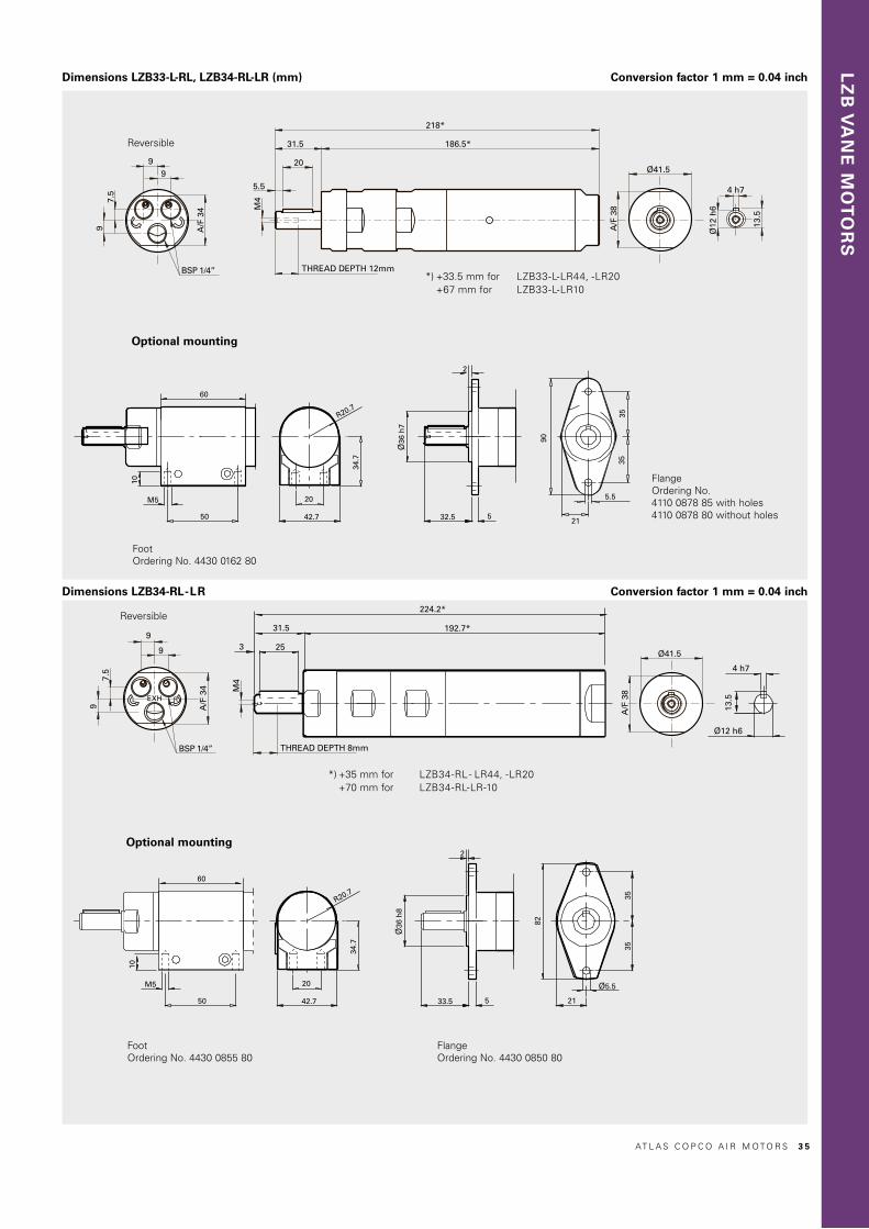
LZ
B V
AN
E M
OT
OR
S
Dimensions LZB33-L-RL, LZB34-RL-LR (mm)
9
99
A/F
34
7.5
BSP 1/4” THREAD DEPTH 12mm
4 h7
Ø12
h6
13.5
31.5
20
5.5
M4
218*
186.5*
A/F
38
Ø41.5
60
10
50
M5 20
42.7
34.7
R20.7
Ø36
h8
33.5 5
2
82
21
Ø5.5
3535
4 h7
Ø12 h613
.5
224.2*
192.7*31.5
253
20
42.7
34.7
R20.7Ø
36 h
7
32.5 5
2
60
10
50
M5
9
9
A/F
34
7.5
BSP 1/4”
9
90
3535
21
5.5
A/F
38
Ø41.5
M4
THREAD DEPTH 8mm
Conversion factor 1 mm = 0.04 inch
Conversion factor 1 mm = 0.04 inch
FlangeOrdering No. 4430 0850 80
Reversible
Reversible
Optional mounting
FootOrdering No. 4430 0855 80
*) +35 mm for LZB34-RL - LR44, -LR20 +70 mm for LZB34-RL-LR-10
Optional mounting
FootOrdering No. 4430 0162 80
*) +33.5 mm for LZB33-L-LR44, -LR20 +67 mm for LZB33-L-LR10
Dimensions LZB34-RL-LR
FlangeOrdering No.4110 0878 85 with holes4110 0878 80 without holes
AT L A S C O P C O A I R M O T O R S 3 5

VANE MOTORS LZB33-LHigh torque and lubrication free0.23 – 0.37 kW0.31 – 0.50 hp
EX certification valid for fixture mounted use only with a maximum surrounding temperature of +40°C (104°F).
For optional vanes and accessories see chapter Accessories.
ModelLubrication free
Maxoutput
kW hp
Speedat maxoutput
r/min
Torqueat maxoutput
Nm lb-ft
Minstartingtorque
Nm lb-ft
Stalltorque
Nm lb-ft
Free speed
r/min
Airconsump-tion at max
outputl/s cfm
Weight
kg lb
Shaft loadingcode 1) ATEX code Ordering No.
Clockwise rotation (Keyed shaft)LZB33-L-A0020-11 0.37 0.50 100 36 27 66 49 72 53 210 8.1 17.2 2.6 5.8 g Ex II 2GD c T6 IIC T85°C 8411 0322 07LZB33-L-A0015-11 0.37 0.50 75 49 36 90 66 98 72 150 8.1 17.2 2.6 5.8 g Ex II 2GD c T6 IIC T85°C 8411 0322 15LZB33-L-A0011-11 0.37 0.50 55 65 48 118 87 130 96 115 8.1 17.2 2.6 5.8 g Ex II 2GD c T6 IIC T85°C 8411 0322 23LZB33-L-A0008-11 0.37 0.50 41 88 65 158 117 176 130 80 8.1 17.2 2.6 5.8 g Ex II 2GD c T6 IIC T85°C 8411 0322 31LZB33-L-A0007-11 0.37 0.50 33 110 81 200 148 220 162 70 8.1 17.2 2.6 5.8 g Ex II 2GD c T6 IIC T85°C 8411 0322 49LZB33-L-A0005-11 0.36 0.48 24 145 107 274 202 290 214 50 8.1 17.2 5.0 11.1 h Ex II 2GD c T6 IIC T85°C 8411 0322 56LZB33-L-A0004-11 0.36 0.48 18 195 144 360 266 390 288 38 8.1 17.2 5.0 11.1 h Ex II 2GD c T6 IIC T85°C 8411 0322 64LZB33-L-A0003-11 0.36 0.48 13 260 192 490 361 520 384 26 8.1 17.2 5.0 11.1 h Ex II 2GD c T6 IIC T85°C 8411 0322 72LZB33-L-A0002-11 0.36 0.48 10 349 257 680 502 698 515 20 8.1 17.2 5.0 11.1 h Ex II 2GD c T6 IIC T85°C 8411 0322 80Reversible (Keyed shaft)LZB33-L-AR0015-11 0.24 0.32 75 31 23 41 30 62 46 140 7.9 16.8 2.6 5.8 g Ex II 2GD c T6 IIC T85°C 8411 0323 06LZB33-L-AR0011-11 0.24 0.32 55 42 31 56 41 84 62 100 7.9 16.8 2.6 5.8 g Ex II 2GD c T6 IIC T85°C 8411 0323 14LZB33-L-AR0008-11 0.24 0.32 41 56 41 74 55 112 83 75 7.9 16.8 2.6 5.8 g Ex II 2GD c T6 IIC T85°C 8411 0323 22LZB33-L-AR0006-11 0.24 0.32 31 75 55 100 74 150 111 60 7.9 16.8 2.6 5.8 g Ex II 2GD c T6 IIC T85°C 8411 0323 30LZB33-L-AR0005-11 0.24 0.32 25 93 69 125 92 186 137 45 7.9 16.8 2.6 5.8 g Ex II 2GD c T6 IIC T85°C 8411 0323 48LZB33-L-AR0004-11 0.23 0.31 18 120 89 169 125 240 177 35 7.9 16.8 5.0 11.1 h Ex II 2GD c T6 IIC T85°C 8411 0323 55LZB33-L-AR0003-11 0.23 0.31 13 165 122 230 170 330 243 25 7.9 16.8 5.0 11.1 h Ex II 2GD c T6 IIC T85°C 8411 0323 63LZB33-L-AR0002-11 0.23 0.31 10 220 162 305 225 440 325 20 7.9 16.8 5.0 11.1 h Ex II 2GD c T6 IIC T85°C 8411 0323 71LZB33-L-AR0001-11 0.23 0.31 7 300 221 412 304 600 443 14 7.9 16.8 5.0 11.1 h Ex II 2GD c T6 IIC T85°C 8411 0323 891) For Shaft loading curves, see page 16. NOTE: - If running motors with 100% dry air and no lubrication, performance can be reduced with 5-15% at max output. - To optimize life time for a lubrication free motor, use lubricated air if the application allows it.
Data at air pressure 6.3 bar (91 psi)
3 6 AT L A S C O P C O A I R M O T O R S
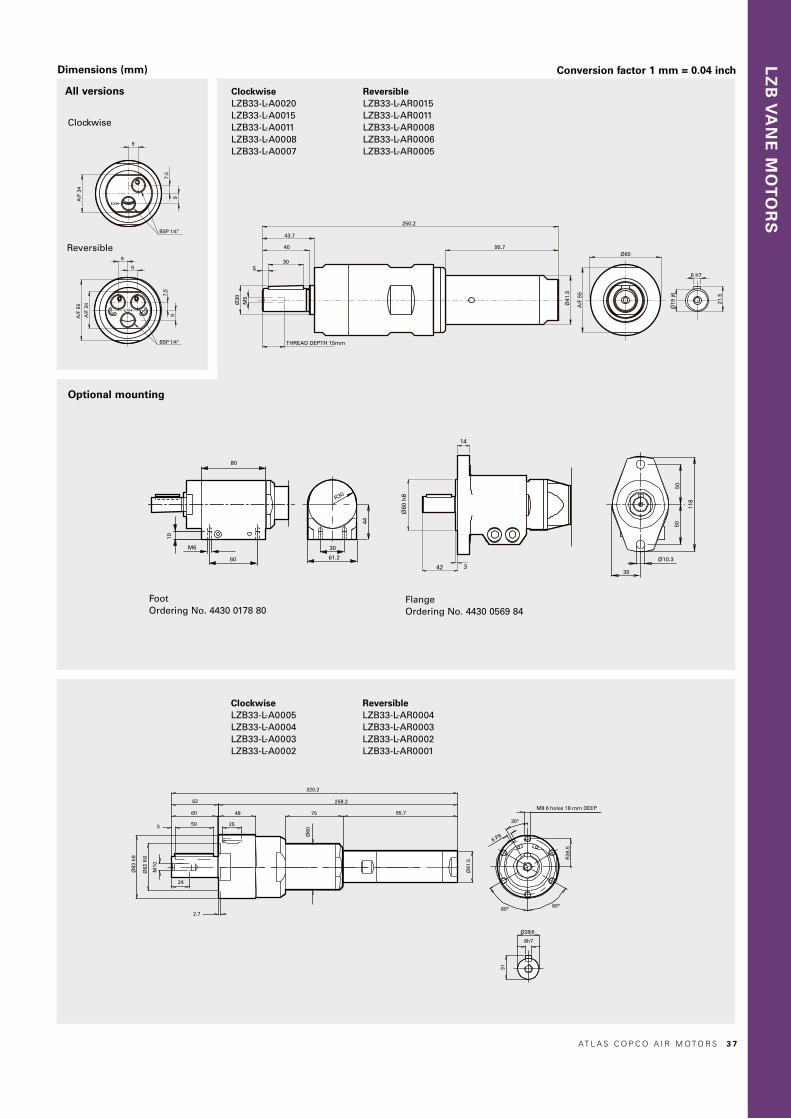
LZ
B V
AN
E M
OT
OR
S
6 h7
Ø19
j6
21.5
Ø30
M5
THREAD DEPTH 15mm
530
40
43.7
250.2
95.7
Ø41
.5
A/F
55
Ø60
320.2
258.2
95.775
Ø41
.5
Ø60
2.7
48
2550
60
62
5
24
Ø83
h9
Ø62
K6
M10
42 3
Ø60
h8
14
M6
60
10
80
61.2
30
44
R30
118
35
Ø10.3
5050
BSP 1/4”
7.5
9
9
A/F
34
9
A/F
55
9
A/F
34
BSP 1/4”
7.5
9
M8 6 holes 18 mm DEEP
6 P9
R36
.5
Ø28j6
8h7
31
Dimensions (mm)
Reversible
Clockwise
All versions
Conversion factor 1 mm = 0.04 inch
Foot Ordering No. 4430 0178 80
FlangeOrdering No. 4430 0569 84
ClockwiseLZB33-L-A0020 LZB33-L-A0015 LZB33-L-A0011 LZB33-L-A0008 LZB33-L-A0007
ClockwiseLZB33-L-A0005 LZB33-L-A0004 LZB33-L-A0003 LZB33-L-A0002
Optional mounting
ReversibleLZB33-L-AR0015 LZB33-L-AR0011 LZB33-L-AR0008 LZB33-L-AR0006 LZB33-L-AR0005
ReversibleLZB33-L-AR0004 LZB33-L-AR0003 LZB33-L-AR0002 LZB33-L-AR0001
AT L A S C O P C O A I R M O T O R S 3 7

Reversible (AR)
LZB33-L high torque motors: Performance curves at 6.3 bar (91 psi)Non-reversible (A)
Nm
80
70
60
50
40
30
20
10
LZB33-L-A0020 l/s
10.5
9.0
7.5
6.0
4.5
3.0
1.5
r/min
kW
0.40
0.35
0.30
0.25
0.20
0.15
0.10
0.05
40 80 120 160 200 240
Nm
140
120
100
80
60
40
20
LZB33-L-A0011 l/s
10.5
9.0
7.5
6.0
4.5
3.0
1.5
r/min
kW
0.40
0.35
0.30
0.25
0.20
0.15
0.10
0.05
20 40 60 80 100 120 140
Nm
210
180
150
120
90
60
30
LZB33-L-A0008 l/s
10.5
9.0
7.5
6.0
4.5
3.0
1.5
r/min
kW
0.40
0.35
0.30
0.25
0.20
0.15
0.10
0.05
20 40 60 80 100
Nm
320
280
240
200
160
120
80
40
LZB33-L-A0005 l/s
10.5
9.0
7.5
6.0
4.5
3.0
1.5
r/min
kW
0.40
0.35
0.30
0.25
0.20
0.15
0.10
0.05
10 20 30 40 50 60
Nm
500
400
300
200
100
LZB33-L-A0004 l/s
10.5
9.0
7.5
6.0
4.5
3.0
1.5
r/min
kW
0.40
0.35
0.30
0.25
0.20
0.15
0.10
0.05
10 20 30 40 50
Nm
600
500
400
300
200
100
LZB33-L-A0003 l/s
10.5
9.0
7.5
6.0
4.5
3.0
1.5
r/min
kW
0.40
0.35
0.30
0.25
0.20
0.15
0.10
0.05
5 10 15 20 25 30 35
Nm
800
700
600
500
400
300
200
100
LZB33-L-A0002 l/s
10.5
9.0
7.5
6.0
4.5
3.0
1.5
r/min
kW
0.40
0.35
0.30
0.25
0.20
0.15
0.10
0.05
4 8 12 16 20 24
Nm
120
105
90
75
60
45
30
15
LZB33-L-A0015 l/s
10.5
9.0
7.5
6.0
4.5
3.0
1.5
r/min
kW
0.40
0.35
0.30
0.25
0.20
0.15
0.10
0.05
40 80 120 160 200
Nm
240
210
180
150
120
90
60
30
LZB33-L-A0007 l/s
10.5
9.0
7.5
6.0
4.5
3.0
1.5
r/min
kW
0.40
0.35
0.30
0.25
0.20
0.15
0.10
0.05
10 20 30 40 50 8060 70
Nm
60
50
40
30
20
10
LZB33-L-AR0015 l/s
10
8
6
4
2
r/min
kW
0.30
0.25
0.20
0.15
0.10
0.05
30 60 90 120 150
Nm
90
75
60
45
30
15
LZB33-L-AR0011 l/s
10
8
6
4
2
r/min
kW
0.30
0.25
0.20
0.15
0.10
0.05
20 40 60 12080 100
Nm
120
100
80
60
40
20
LZB33-L-AR0008 l/s
10
8
6
4
2
r/min
kW
0.30
0.25
0.20
0.15
0.10
0.05
20 40 60 80 100
Nm
150
120
90
60
30
LZB33-L-AR0006 l/s
10
8
6
4
2
r/min
kW
0.30
0.25
0.20
0.15
0.10
0.05
10 20 30 6040 50
Nm
180
150
120
90
60
30
LZB33-L-AR0005 l/s
10
8
6
4
2
r/min
kW
0.30
0.25
0.20
0.15
0.10
0.05
10 20 30 5040
Nm
250
200
150
100
50
LZB33-L-AR0004 l/s
10
8
6
4
2
r/min
kW
0.30
0.25
0.20
0.15
0.10
0.05
5 10 15 4020 25 30 35
Nm
400
300
200
100
LZB33-L-AR0003 l/s
10
8
6
4
2
kW
0.30
0.25
0.20
0.15
0.10
0.05
5 10 3015 20 25
Nm
500
400
300
200
100
LZB33-L-AR0002 l/s
10
8
6
4
2
kW
0.30
0.25
0.20
0.15
0.10
0.05
4 8 2012 16 r/min
Nm
600
500
400
300
200
100
LZB33-L-AR0001 l/s
10
8
6
4
2
kW
0.30
0.25
0.20
0.15
0.10
0.05
3 6 159 12 r/min
3 8 AT L A S C O P C O A I R M O T O R S

LZ
B V
AN
E M
OT
OR
S
VANE MOTORS LZB33-LB Brake module, lubrication free and reversibleLZB34-RLB Stainless steel, brake module, lubrication free and reversible0.23 – 0.25 kW0.31 – 0.34 hp
Braking torque from 0.55–520 Nm.The brake is activated by spring force and released by air pressure.
Stainless steel version:
• 100% Silicon free• Grease that conforms to Food Grade regulations
EX certification valid for fixture mounted use only with a maximum surrounding temperature of +40°C (104°F).
Data at air pressure 6.3 bar (91 psi)
Model Lubrication free
Maxoutput
kW hp
Speedat maxoutput
r/min
Torqueat maxoutput
Nm lb-ft
Minstarting torque
Nm lb-ft
Stalltorque
Nm lb-ft
Braking torque
Nm lb-ft
Free speed
r/min
Airconsump-tion at max
outputl/s cfm
Weight
kg lb
Shaft loading code 1) ATEX code Ordering No.
Reversible (Keyed shaft)LZB33-LB-AR150-11 0.25 0.34 7000 0.34 0.25 0.46 0.34 0.68 0.5 0.55 0.4 13300 7.9 16.8 1.35 2.97 c Ex II 2GD c T4 IIC T110°C 8411 0340 05LZB33-LB-AR043-11 0.25 0.34 1960 1.2 0.89 1.6 1.2 2.4 1.8 2.0 1.5 3800 7.9 16.8 1.35 2.97 c Ex II 2GD c T6 IIC T85°C 8411 0340 13LZB33-LB-AR024-11 0.25 0.34 1090 2.2 1.6 3.0 2.2 4.4 3.2 3.5 2.6 2000 7.9 16.8 1.35 2.97 c Ex II 2GD c T6 IIC T85°C 8411 0340 21LZB33-LB-AR019-11 0.25 0.34 880 2.7 2.0 3.7 2.7 5.4 4.0 4.4 3.2 1700 7.9 16.8 1.35 2.97 c Ex II 2GD c T6 IIC T85°C 8411 0340 39LZB33-LB-AR009-11 0.25 0.34 430 5.4 4.0 7.0 5.2 10.8 8.0 8.9 6.6 800 7.9 16.8 1.63 3.59 c Ex II 2GD c T6 IIC T85°C 8411 0340 47LZB33-LB-AR005-11 0.25 0.34 240 9.8 7.2 12.6 9.3 19.6 14.5 16 12 450 7.9 16.8 1.63 3.59 c Ex II 2GD c T6 IIC T85°C 8411 0340 54LZB33-LB-AR004-11 0.25 0.34 190 12.1 8.9 15.6 11.5 24 17.8 20 15 360 7.9 16.8 1.63 3.59 c Ex II 2GD c T6 IIC T85°C 8411 0340 62LZB33-LB-AR0026-11 2 0.24 0.32 120 19 14 20 14.8 38 28 32 24 230 7.9 16.8 2.1 4.6 d Ex II 2GD c T6 IIC T85°C 8411 0340 70LZB33-LB-AR0015-11 0.24 0.32 75 31 23 41 30 62 46 52 38 140 7.9 16.8 3.2 7.0 g Ex II 2GD c T6 IIC T85°C 8411 0340 88LZB33-LB-AR0011-11 0.24 0.32 55 42 31 56 41 84 62 71 52 100 7.9 16.8 3.2 7.0 g Ex II 2GD c T6 IIC T85°C 8411 0340 96LZB33-LB-AR0008-11 0.24 0.32 41 56 41 74 55 112 83 93 67 75 7.9 16.8 3.2 7.0 g Ex II 2GD c T6 IIC T85°C 8411 0341 04LZB33-LB-AR0006-11 0.24 0.32 31 75 55 100 74 150 111 130 95 60 7.9 16.8 3.2 7.0 g Ex II 2GD c T6 IIC T85°C 8411 0341 12LZB33-LB-AR0005-11 0.24 0.32 25 93 69 125 92 186 137 160 120 45 7.9 16.8 3.2 7.0 g Ex II 2GD c T6 IIC T85°C 8411 0341 20LZB33-LB-AR0004-11 0.23 0.31 18 120 89 169 125 240 177 210 160 35 7.9 16.8 5.6 12.3 h Ex II 2GD c T6 IIC T85°C 8411 0341 38LZB33-LB-AR0003-11 0.23 0.31 13 165 122 230 170 330 243 290 210 25 7.9 16.8 5.6 12.3 h Ex II 2GD c T6 IIC T85°C 8411 0341 46LZB33-LB-AR0002-11 0.23 0.31 10 220 162 305 225 440 325 380 280 20 7.9 16.8 5.6 12.3 h Ex II 2GD c T6 IIC T85°C 8411 0341 53LZB33-LB-AR0001-11 0.23 0.31 7 300 221 412 304 600 443 520 380 14 7.9 16.8 5.6 12.3 h Ex II 2GD c T6 IIC T85°C 8411 0341 61Stainless steel Reversible (Keyed shaft)LZB34-RLB-AR150-11 0.25 0.34 7000 0.34 0.25 0.46 0.34 0.68 0.5 0.55 0.4 13300 7.9 16.8 1.39 3.06 c Ex II 2GD c T4 IIC T110°C 8411 0341 79LZB34-RLB-AR043-11 0.25 0.34 1960 1.2 0.89 1.6 1.2 2.4 1.8 2.0 1.5 3800 7.9 16.8 1.39 3.06 c Ex II 2GD c T6 IIC T85°C 8411 0341 87LZB34-RLB-AR024-11 0.25 0.34 1090 2.2 1.6 3.0 2.2 4.4 3.2 3.5 2.6 2000 7.9 16.8 1.39 3.06 c Ex II 2GD c T6 IIC T85°C 8411 0341 95LZB34-RLB-AR019-11 0.25 0.34 880 2.7 2.0 3.7 2.7 5.4 4.0 4.4 3.2 1700 7.9 16.8 1.39 3.06 c Ex II 2GD c T6 IIC T85°C 8411 0342 03LZB34-RLB-AR009-11 0.25 0.34 430 5.4 4.0 7.0 5.2 10.8 8.0 9.0 6.6 800 7.9 16.8 1.66 3.66 c Ex II 2GD c T6 IIC T85°C 8411 0342 11LZB34-RLB-AR005-11 0.25 0.34 240 9.8 7.2 12.6 9.3 19.6 14.5 16 12 450 7.9 16.8 1.66 3.66 c Ex II 2GD c T6 IIC T85°C 8411 0342 29LZB34-RLB-AR004-11 0.25 0.34 190 12.1 8.9 15.6 11.5 24 17.7 20 15 360 7.9 16.8 1.66 3.66 c Ex II 2GD c T6 IIC T85°C 8411 0342 371) For Shaft loading curves, see page 16.2) Flange is mounted and supplied with the motor.
The brake needs minimum 3 bar to release. Performance curves same as standard motors, see page 33 and 38.
NOTE: - If running motors with 100% dry air and no lubrication, performance can be reduced with 5-15% at max output. - To optimize life time for a lubrication free motor, use lubricated air if the application allows it.
For optional stainless steel motor cell, vane kits and other accessories see chapter Accessories.
AT L A S C O P C O A I R M O T O R S 3 9

Dimensions (mm) Conversion factor 1 mm = 0.04 inch
42 3
Ø60
h8
14
Ø19
j6
6 h7
21.5
A/F 34
BSP 1/4”
65
9
7.5
9
9
Ø30
M5
44
40
530
THREAD DEPTH 15mm
304.5
150
100 14
A/F
55
Ø60
3
31.5
25
205.5*
174*
100 14
Ø41
.5
4h7
Ø12h6
13.5
Ø41
.5
Ø36
h7
2
32.5 5
90
3535
21
5.5Ø
36 h
833.5 5
2
82
3535
5.5
21
9
9
7.5
9
A/F 34
55
BSP 1/4”
Ø14
j6
16.1
5 h7
Ø42
h9
16.2
8
M4
12 Thread depth
2
25
30
35
17
7
250
100 14
Ø41
.5
Ø6.
5
54 70
375
313
15075
100 14
Ø41
.5
Ø60
2.7
48
2550
60
62
5
24
83 h
9
Ø62
K6
M10
10
M5 50
60
20
42.7
R20.7
34.7
Thread length 8
M4
M660
10
80
61.2
30
44
R30
285
Ø41
.5
Ø28j6
8h7
31
M8 6 holes 18 mm DEEP
6 P9
R36
.5
A/F 34
9
7.5
99
BSP 1/4”
55
42 3
Ø60
h8
14
Ø19
j6
6 h7
21.5
A/F 34
BSP 1/4”
65
9
7.5
9
9
Ø30
M5
44
40
530
THREAD DEPTH 15mm
304.5
150
100 14
A/F
55
Ø60
3
31.5
25
205.5*
174*
100 14
Ø41
.5
4h7
Ø12h6
13.5
Ø41
.5
Ø36
h7
2
32.5 5
90
3535
21
5.5
Ø36
h8
33.5 5
2
82
3535
5.5
21
9
9
7.5
9
A/F 34
55
BSP 1/4”
Ø14
j6
16.1
5 h7
Ø42
h9
16.2
8
M4
12 Thread depth
2
25
30
35
17
7
250
100 14
Ø41
.5
Ø6.
5
54 70
375
313
15075
100 14
Ø41
.5
Ø60
2.7
48
2550
60
62
5
24
83 h
9
Ø62
K6
M10
10
M5 50
60
20
42.7
R20.7
34.7
Thread length 8
M4
M660
10
80
61.2
30
44
R30
285
Ø41
.5
Ø28j6
8h7
31
M8 6 holes 18 mm DEEP
6 P9
R36
.5
A/F 34
9
7.5
99
BSP 1/4”
55
Foot Ordering No. 4430 0162 80
Stainless footOrdering No. 4430 0855 80
LZB33-LB, FlangeOrdering No.4110 0878 85 with holes4110 0878 80 without holes
LZB34-RLB, Stainless flangeOrdering No. 4430 0850 80
*) +34 mm for LZB33-LB-AR009 LZB33-LB-AR005 LZB33-LB-AR004
Reversible with brakeLZB33-LB-AR150LZB33-LB-AR043LZB33-LB-AR024LZB33-LB-AR019
*) +39 mm for LZB34-RLB-AR009 LZB34-RLB-AR005 LZB34-RLB-AR004
*) +4 mm for LZB34-RLB-AR150 LZB34-RLB-AR043 LZB34-RLB-AR024 LZB34-RLB-AR019
Optional mounting
Reversible with brake LZB33-LB-AR0026
4 0 AT L A S C O P C O A I R M O T O R S
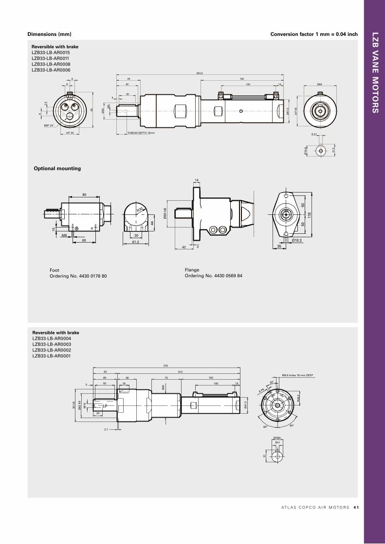
LZ
B V
AN
E M
OT
OR
S
Dimensions (mm) Conversion factor 1 mm = 0.04 inch
42 3
Ø60
h8
14
Ø19
j6
6 h7
21.5
A/F 34
BSP 1/4”
65
9
7.5
9
9
Ø30
M5
44
40
530
THREAD DEPTH 15mm
304.5
150
100 14
A/F
55
Ø60
3
31.5
25
205.5*
174*
100 14
Ø41
.5
4h7
Ø12h6
13.5
Ø41
.5
Ø36
h7
2
32.5 5
90
3535
21
5.5
Ø36
h8
33.5 5
2
82
3535
5.5
21
9
9
7.5
9
A/F 34
55
BSP 1/4”
Ø14
j6
16.1
5 h7
Ø42
h9
16.2
8
M4
12 Thread depth
2
25
30
35
17
7
250
100 14
Ø41
.5
Ø6.
5
54 70
375
313
15075
100 14
Ø41
.5
Ø60
2.7
48
2550
60
62
5
24
83 h
9
Ø62
K6
M10
10
M5 50
60
20
42.7
R20.7
34.7
Thread length 8
M4
M660
10
80
61.2
30
44
R30
285
Ø41
.5
Ø28j6
8h7
31
M8 6 holes 18 mm DEEP
6 P9
R36
.5
A/F 34
9
7.5
99
BSP 1/4”
55
Reversible with brake LZB33-LB-AR0015LZB33-LB-AR0011LZB33-LB-AR0008LZB33-LB-AR0006
Reversible with brake LZB33-LB-AR0004LZB33-LB-AR0003LZB33-LB-AR0002LZB33-LB-AR0001
Optional mounting
FootOrdering No. 4430 0178 80
FlangeOrdering No. 4430 0569 84
AT L A S C O P C O A I R M O T O R S 4 1

VANE MOTORS LZB420.50 – 0.71 kW0.67 – 0.95 hp
EX certification valid for fixture mounted use only with a maximum surrounding temperature of +40°C (104°F).
For optional vanes and accessories see chapter Accessories.
ModelLubricated
Maxoutput
kW hp
Speedat maxoutput
r/min
Torqueat maxoutput
Nm lb-ft
Minstartingtorque
Nm lb-ft
Stalltorque
Nm lb-ft
Free speed
r/min
Airconsumption
at maxoutput
l/s cfm
Weight
kg lb
Shaft loadingcode 1) ATEX code Ordering No.
Clockwise rotation (Keyed shaft) LZB42-A200-11 0.71 0.95 10000 0.68 0.5 1.09 0.8 1.4 1.0 19000 13.0 28.0 1.2 2.65 e Ex II 2GD c T4 IIC T110°C 8411 0420 08LZB42-A065-11 0.71 0.95 3100 2.2 1.6 3.5 2.6 4.4 3.2 6100 13.0 28.0 1.2 2.65 e Ex II 2GD c T4 IIC T110°C 8411 0420 16LZB42-A040-11 0.71 0.95 1960 3.5 2.6 5.6 4.1 7.0 5.2 3800 13.0 28.0 1.2 2.65 e Ex II 2GD c T4 IIC T110°C 8411 0420 24LZB42-A025-11 0.71 0.95 1180 5.8 4.3 9.3 6.9 11.6 8.6 2200 13.0 28.0 1.2 2.65 e Ex II 2GD c T4 IIC T110°C 8411 0420 32LZB42-A015-11 0.70 0.94 690 9.7 7.2 15.5 11.4 19.4 14.3 1300 13.0 28.0 1.25 2.75 e Ex II 2GD c T6 IIC T85°C 8411 0420 40LZB42-A010-11 0.70 0.94 440 15.1 11.1 24 18 30 22 850 13.0 28.0 1.25 2.75 e Ex II 2GD c T6 IIC T85°C 8411 0420 57LZB42-A005-11 0.70 0.94 260 25 18.4 40 30 50 37 500 13.0 28.0 1.25 2.75 e Ex II 2GD c T6 IIC T85°C 8411 0420 65LZB42-A0030-11 0.68 0.91 150 44 32 70 52 88 65 270 13.0 28.0 2.7 5.8 g Ex II 2GD c T6 IIC T85°C 8411 0420 73LZB42-A0020-11 0.68 0.91 95 69 51 110 81 138 102 180 13.0 28.0 2.7 5.8 g Ex II 2GD c T6 IIC T85°C 8411 0420 81LZB42-A0012-11 0.68 0.91 55 114 84 182 134 228 168 105 13.0 28.0 2.7 5.8 g Ex II 2GD c T6 IIC T85°C 8411 0420 99LZB42-A0008-11 0.66 0.89 37 173 128 277 204 346 255 70 13.0 28.0 4.9 10.7 h Ex II 2GD c T6 IIC T85°C 8411 0421 07LZB42-A0005-11 0.66 0.89 23 272 201 435 321 544 401 42 13.0 28.0 4.9 10.7 h Ex II 2GD c T6 IIC T85°C 8411 0421 15Reversible (Keyed shaft)LZB42-AR170-11 0.53 0.71 8000 0.63 0.46 0.85 0.63 1.3 1.0 14200 12.5 27.0 1.2 2.65 e Ex II 2GD c T4 IIC T110°C 8411 0423 05LZB42-AR050-11 0.53 0.71 2500 2.0 1.5 2.7 2.0 4.0 3.0 4500 12.5 27.0 1.2 2.65 e Ex II 2GD c T4 IIC T110°C 8411 0423 13LZB42-AR030-11 0.53 0.71 1570 3.2 2.4 4.3 3.2 6.4 4.7 2800 12.5 27.0 1.2 2.65 e Ex II 2GD c T4 IIC T110°C 8411 0423 21LZB42-AR020-11 0.53 0.71 940 5.4 4.0 7.3 5.4 10.8 8.0 1700 12.5 27.0 1.2 2.65 e Ex II 2GD c T4 IIC T110°C 8411 0423 39LZB42-AR010-11 0.52 0.70 550 9.0 6.6 12.2 9.0 18 13.3 980 12.5 27.0 1.25 2.75 e Ex II 2GD c T6 IIC T85°C 8411 0423 47LZB42-AR007-11 0.52 0.70 350 14 10.3 18.9 13.9 28 21 640 12.5 27.0 1.25 2.75 e Ex II 2GD c T6 IIC T85°C 8411 0423 54LZB42-AR004-11 0.52 0.70 210 23 17 31 23 46 34 375 12.5 27.0 1.25 2.75 e Ex II 2GD c T6 IIC T85°C 8411 0423 62LZB42-AR0025-11 0.51 0.68 120 41 30 55 41 82 60 210 12.5 27.0 2.7 5.8 g Ex II 2GD c T6 IIC T85°C 8411 0423 70LZB42-AR0015-11 0.51 0.68 75 64 47 86 63 128 94 140 12.5 27.0 2.7 5.8 g Ex II 2GD c T6 IIC T85°C 8411 0423 88LZB42-AR0010-11 0.51 0.68 46 106 78 143 105 212 156 80 12.5 27.0 2.7 5.8 g Ex II 2GD c T6 IIC T85°C 8411 0423 96LZB42-AR0006-11 0.50 0.67 29 162 119 219 162 324 239 50 12.5 27.0 4.9 10.7 h Ex II 2GD c T6 IIC T85°C 8411 0424 04LZB42-AR0004-11 0.50 0.67 19 255 188 344 254 510 376 33 12.5 27.0 4.9 10.7 h Ex II 2GD c T6 IIC T85°C 8411 0424 121) For Shaft loading curves, see page 16.
Data at air pressure 6.3 bar (91 psi)
4 2 AT L A S C O P C O A I R M O T O R S
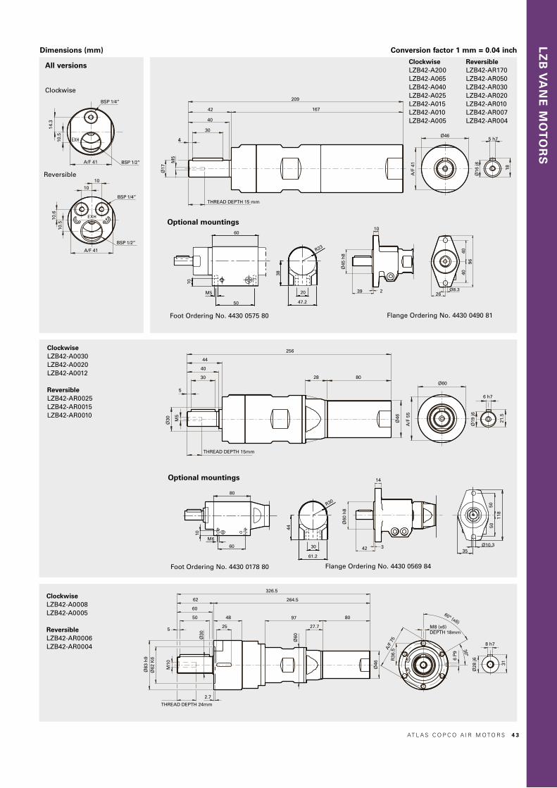
LZ
B V
AN
E M
OT
OR
S
Dimensions (mm) Conversion factor 1 mm = 0.04 inch
Ø16
j6
5 h7
18
A/F 41
10.6
BSP 1/4”
BSP 1/2”
10.5
10
10
Ø17
M5
4
42
40
30
THREAD DEPTH 15 mm
209
167
A/F
41
Ø46
BSP 1/4”
BSP 1/2”A/F 41
10.5
14.3
Ø19
j6
6 h7
21.5
Ø30 M
5
5
44
40
30
THREAD DEPTH 15mm
256
28 80
Ø46
A/F
55
Ø60
Ø83
h9
THREAD DEPTH 24mm
Ø62
K6
Ø30
M10
2.7
5
62
60
50 48
25
326.5
264.5
97 80
27.7
Ø60
Ø46
A/F
75
R36
.5
M8 (x6)DEPTH 18mm
6 P
9
8 h7
Ø28
j6
31
42 3
Ø60
h8
14
118
5050
35Ø10.3
26Ø8.3
4040
96
39 2
Ø45
h8
10
44
30
61.2
R30
3820
47.2
10
50
60
M5
R23
60
M6
10
80Ø
16 j6
5 h7
18
A/F 41
10.6
BSP 1/4”
BSP 1/2”
10.5
10
10
Ø17
M5
4
42
40
30
THREAD DEPTH 15 mm
209
167
A/F
41
Ø46
BSP 1/4”
BSP 1/2”A/F 41
10.5
14.3
Ø19
j6
6 h7
21.5
Ø30 M
5
5
44
40
30
THREAD DEPTH 15mm
256
28 80
Ø46
A/F
55
Ø60
Ø83
h9
THREAD DEPTH 24mm
Ø62
K6
Ø30
M10
2.7
5
62
60
50 48
25
326.5
264.5
97 80
27.7
Ø60
Ø46
A/F
75
R36
.5
M8 (x6)DEPTH 18mm
6 P
9
8 h7
Ø28
j6
31
42 3
Ø60
h8
14
118
5050
35Ø10.3
26Ø8.3
4040
96
39 2
Ø45
h8
10
44
30
61.2
R30
38
20
47.2
10
50
60
M5
R23
60
M6
10
80
Ø16
j6
5 h7
18
A/F 41
10.6
BSP 1/4”
BSP 1/2”
10.5
10
10
Ø17
M5
4
42
40
30
THREAD DEPTH 15 mm
209
167
A/F
41
Ø46
BSP 1/4”
BSP 1/2”A/F 41
10.5
14.3
Ø19
j6
6 h7
21.5
Ø30 M
5
5
44
40
30
THREAD DEPTH 15mm
256
28 80
Ø46
A/F
55
Ø60
Ø83
h9
THREAD DEPTH 24mm
Ø62
K6
Ø30
M10
2.7
5
62
60
50 48
25
326.5
264.5
97 80
27.7
Ø60
Ø46
A/F
75
R36
.5
M8 (x6)DEPTH 18mm
6 P
9
8 h7
Ø28
j6
31
42 3
Ø60
h8
14
118
5050
35Ø10.3
26Ø8.3
4040
96
39 2
Ø45
h8
10
44
30
61.2
R30
38
20
47.2
10
50
60
M5
R23
60
M6
10
80
Reversible
All versions
Clockwise
ClockwiseLZB42-A200 LZB42-A065 LZB42-A040 LZB42-A025 LZB42-A015 LZB42-A010 LZB42-A005
ReversibleLZB42-AR170 LZB42-AR050 LZB42-AR030 LZB42-AR020 LZB42-AR010 LZB42-AR007 LZB42-AR004
ClockwiseLZB42-A0030 LZB42-A0020 LZB42-A0012
ReversibleLZB42-AR0025 LZB42-AR0015 LZB42-AR0010
ClockwiseLZB42-A0008 LZB42-A0005
ReversibleLZB42-AR0006 LZB42-AR0004
Optional mountings
Ø16
j6
5 h7
18
A/F 41
10.6
BSP 1/4”
BSP 1/2”
10.5
10
10
Ø17
M5
4
42
40
30
THREAD DEPTH 15 mm
209
167
A/F
41
Ø46
BSP 1/4”
BSP 1/2”A/F 41
10.5
14.3
Ø19
j6
6 h7
21.5
Ø30 M
5
5
44
40
30
THREAD DEPTH 15mm
256
28 80
Ø46
A/F
55
Ø60
Ø83
h9
THREAD DEPTH 24mm
Ø62
K6
Ø30
M10
2.7
5
62
60
50 48
25
326.5
264.5
97 80
27.7
Ø60
Ø46
A/F
75
R36
.5
M8 (x6)DEPTH 18mm
6 P
9
8 h7
Ø28
j6
31
42 3
Ø60
h8
14
118
5050
35Ø10.3
26Ø8.3
4040
96
39 2
Ø45
h8
10
44
30
61.2
R30
38
20
47.2
10
50
60
M5
R23
60
M6
10
80
Flange Ordering No. 4430 0490 81Foot Ordering No. 4430 0575 80
Optional mountings
Flange Ordering No. 4430 0569 84Foot Ordering No. 4430 0178 80
AT L A S C O P C O A I R M O T O R S 4 3

Nm
1.4
1.2
1.0
0.8
0.6
0.4
0.2
LZB42-A200 l/s
18
15
12
9
6
3
r/min
kW
0.8
0.7
0.6
0.5
0.4
0.3
0.2
0.1
4000 8000 12000 16000 20000 24000
Nm
5
4
3
2
1
LZB42-A065 l/s
18
15
12
9
6
3
r/min
kW
0.8
0.7
0.6
0.5
0.4
0.3
0.2
0.1
1000 2000 3000 4000 70005000 6000
Nm
8
7
6
5
4
3
2
1
LZB42-A040 l/s
18
15
12
9
6
3
r/min
kW
0.8
0.7
0.6
0.5
0.4
0.3
0.2
0.1
1000 2000 3000 4000 5000
Nm
12.0
10.5
9.0
7.5
6.0
4.5
3.0
1.5
LZB42-A025 l/s
18
15
12
9
6
3
r/min
kW
0.8
0.7
0.6
0.5
0.4
0.3
0.2
0.1
500 1000 1500 2000 2500
Nm
21
18
15
12
9
6
3
LZB42-A015 l/s
18
15
12
9
6
3
r/min
kW
0.8
0.7
0.6
0.5
0.4
0.3
0.2
0.1
300 600 900 1200 1500
Nm
32
28
24
20
16
12
8
4
LZB42-A010 l/s
18
15
12
9
6
3
r/min
kW
0.8
0.7
0.6
0.5
0.4
0.3
0.2
0.1
200 400 600 800 1000
Nm
60
50
40
30
20
10
LZB42-A005 l/s
18
15
12
9
6
3
r/min
kW
0.8
0.7
0.6
0.5
0.4
0.3
0.2
0.1
100 200 300 400 600500
Nm
90
75
60
45
30
15
LZB42-A0030 l/s
18
15
12
9
6
3
r/min
kW
0.8
0.7
0.6
0.5
0.4
0.3
0.2
0.1
50 100 150 200 350250 300
Nm
140
120
100
80
60
40
20
LZB42-A0020 l/s
18
15
12
9
6
3
r/min
kW
0.8
0.7
0.6
0.5
0.4
0.3
0.2
0.1
40 80 120 200160
Nm
240
210
180
150
120
90
60
30
LZB42-A0012 l/s
18
15
12
9
6
3
r/min
kW
0.8
0.7
0.6
0.5
0.4
0.3
0.2
0.1
20 40 60 12080 100
Nm
400
350
300
250
200
150
100
50
LZB42-A0008 l/s
18
15
12
9
6
3
r/min
kW
0.8
0.7
0.6
0.5
0.4
0.3
0.2
0.1
10 20 30 8040 50 60 70
Nm
600
500
400
300
200
100
LZB42-A0005 l/s
18
15
12
9
6
3
r/min
kW
0.8
0.7
0.6
0.5
0.4
0.3
0.2
0.1
10 20 30 40 50
LZB42: Performance curves at air pressure 6.3 bar (91 psi)Non-reversible (A)
Conversion factors1 kW = 1.34 hp1 Nm = 0.74 Ibf - ft1 l/s = 2.1 cfm
1 hp = 0.75 kW1 Ibf-ft = 1.36 Nm1 cfm = 0.47 l/s
TorqueNmPowerkW
Maxoutput
Torqueat maxoutput
Torque
Power
Speed r/min
Air. cons.
Air cons.l/s
For information about performance curves, see page 7.
4 4 AT L A S C O P C O A I R M O T O R S

Nm
1.5
1.2
0.9
0.6
0.3
LZB42-AR170 l/s
16
12
8
4
r/min
kW
0.6
0.5
0.4
0.3
0.2
0.1
4000 8000 12000 16000
Nm
5
4
3
2
1
LZB42-AR050 l/s
16
12
8
4
r/min
kW
0.6
0.5
0.4
0.3
0.2
0.1
1000 2000 3000 50004000
Nm
7.5
6.0
4.5
3.0
1.5
LZB42-AR030 l/s
16
12
8
4
r/min
kW
0.6
0.5
0.4
0.3
0.2
0.1
500 1000 1500 35002000 2500 3000
Nm
12
10
8
6
4
2
LZB42-AR020 l/s
16
12
8
4
r/min
kW
0.6
0.5
0.4
0.3
0.2
0.1
400 800 20001200 1600
Nm
20
16
12
8
4
LZB42-AR010 l/s
16
12
8
4
r/min
kW
0.6
0.5
0.4
0.3
0.2
0.1
200 400 1200600 800 1000
Nm
30
25
20
15
10
5
LZB42-AR007 l/s
16
12
8
4
r/min
kW
0.6
0.5
0.4
0.3
0.2
0.1
100 200 700300 400 500 600
Nm
50
40
30
20
10
LZB42-AR004 l/s
16
12
8
4
r/min
kW
0.6
0.5
0.4
0.3
0.2
0.1
100 500200 300 400
Nm
90
75
60
45
30
15
LZB42-AR0025 l/s
16
12
8
4
r/min
kW
0.6
0.5
0.4
0.3
0.2
0.1
40 24080 120 160 200
Nm
150
120
90
60
30
LZB42-AR0015 l/s
16
12
8
4
r/min
kW
0.6
0.5
0.4
0.3
0.2
0.1
20 16040 60 80 100 120 140
Nm
240
200
160
120
80
40
LZB42-AR0010 l/s
16
12
8
4
r/min
kW
0.6
0.5
0.4
0.3
0.2
0.1
10020 40 60 80
Nm
400
300
200
100
LZB42-AR0006 l/s
16
12
8
4
r/min
kW
0.6
0.5
0.4
0.3
0.2
0.1
6010 20 30 40 50
Nm
600
500
400
300
200
100
LZB42-AR0004 l/s
16
12
8
4
r/min
kW
0.6
0.5
0.4
0.3
0.2
0.1
405 10 15 20 25 30 35
LZB42: Performance curves at air pressure 6.3 bar (91 psi)Reversible (AR)
LZ
B V
AN
E M
OT
OR
S
Conversion factors1 kW = 1.34 hp1 Nm = 0.74 Ibf - ft1 l/s = 2.1 cfm
1 hp = 0.75 kW1 Ibf-ft = 1.36 Nm1 cfm = 0.47 l/s
TorqueNmPowerkW
Maxoutput
Torqueat maxoutput
Torque
Power
Speed r/min
Air. cons.
Air cons.l/s
For information about performance curves, see page 7.
AT L A S C O P C O A I R M O T O R S 4 5

VANE MOTORS LZB460.59 – 0.84 kW0.79 – 1.13 hp
EX certification valid for fixture mounted use only with a maximum surrounding temperature of +40°C (104°F).
For optional vanes and accessories see chapter Accessories.
ModelLubricated
Maxoutput
kW hp
Speedat maxoutput
r/min
Torqueat maxoutput
Nm lb-ft
Minstartingtorque
Nm lb-ft
Stalltorque
Nm lb-ft
Free speed
r/min
Airconsumption
at maxoutput
l/s cfm
Weight
kg lb
Shaft loadingcode 1) ATEX code Ordering No.
Clockwise rotation (Keyed shaft) LZB46-A200-11 0.84 1.13 10800 0.74 0.55 1.2 0.89 1.48 1.09 20000 16.2 34.4 1.2 2.65 e Ex II 2GD c T4 IIC T110°C 8411 0460 09LZB46-A065-11 0.84 1.13 3300 2.4 1.8 3.9 2.9 4.8 3.5 6300 16.2 34.4 1.2 2.65 e Ex II 2GD c T4 IIC T110°C 8411 0460 17LZB46-A040-11 0.84 1.13 2100 3.8 2.8 6.1 4.5 7.6 5.6 4000 16.2 34.4 1.2 2.65 e Ex II 2GD c T4 IIC T110°C 8411 0460 25LZB46-A025-11 0.84 1.13 1270 6.3 4.6 10 7.4 12.6 9.3 2400 16.2 34.4 1.2 2.65 e Ex II 2GD c T4 IIC T110°C 8411 0460 33LZB46-A015-11 0.82 1.10 740 10.5 7.7 17 12.5 21 15.5 1400 16.2 34.4 1.3 2.9 e Ex II 2GD c T6 IIC T85°C 8411 0460 41LZB46-A010-11 0.82 1.10 480 16.5 12.2 26 19.2 33 24.3 900 16.2 34.4 1.3 2.9 e Ex II 2GD c T6 IIC T85°C 8411 0460 58LZB46-A005-11 0.82 1.10 280 27 20 44 32 55 41 540 16.2 34.4 1.3 2.9 e Ex II 2GD c T6 IIC T85°C 8411 0460 66LZB46-A0030-11 0.81 1.09 160 48 35 77 57 95 70 300 16.2 34.4 2.7 6.0 g Ex II 2GD c T6 IIC T85°C 8411 0460 74LZB46-A0020-11 0.81 1.09 105 75 55 121 89 149 110 200 16.2 34.4 2.7 6.0 g Ex II 2GD c T6 IIC T85°C 8411 0460 82LZB46-A0012-11 0.81 1.09 62 124 91 201 148 248 183 115 16.2 34.4 2.7 6.0 g Ex II 2GD c T6 IIC T85°C 8411 0460 90LZB46-A0008-11 0.79 1.06 39 191 141 309 228 382 282 70 16.2 34.4 4.9 10.8 h Ex II 2GD c T6 IIC T85°C 8411 0461 08LZB46-A0005-11 0.79 1.06 25 299 221 485 358 598 441 45 16.2 34.4 4.9 10.8 h Ex II 2GD c T6 IIC T85°C 8411 0461 16Clockwise rotation (Threaded shaft)LZB46-A200-12 0.84 1.13 10800 0.74 0.55 1.2 0.89 1.48 1.09 20000 16.2 34.4 1.2 2.65 e Ex II 2GD c T4 IIC T110°C 8411 0469 00LZB46-A065-12 0.84 1.13 3300 2.4 1.8 3.9 2.9 4.8 3.5 6300 16.2 34.4 1.2 2.65 e Ex II 2GD c T4 IIC T110°C 8411 0469 18LZB46-A040-12 0.84 1.13 2100 3.8 2.8 6.1 4.5 7.6 5.6 4000 16.2 34.4 1.2 2.65 e Ex II 2GD c T4 IIC T110°C 8411 0469 26LZB46-A025-12 0.84 1.13 1270 6.3 4.6 10 7.4 12.6 9.3 2400 16.2 34.4 1.2 2.65 e Ex II 2GD c T4 IIC T110°C 8411 0469 34LZB46-A015-12 0.82 1.10 740 10.5 7.7 17 12.5 21 15.5 1400 16.2 34.4 1.3 2.9 e Ex II 2GD c T6 IIC T85°C 8411 0469 42LZB46-A010-12 0.82 1.10 480 16.5 12.2 26 19.2 33 24.3 900 16.2 34.4 1.3 2.9 e Ex II 2GD c T6 IIC T85°C 8411 0469 59LZB46-A005-12 0.82 1.10 280 27 20 44 32 55 41 540 16.2 34.4 1.3 2.9 e Ex II 2GD c T6 IIC T85°C 8411 0469 67LZB46-A0030-12 0.81 1.09 160 48 35 77 57 95 70 300 16.2 34.4 2.7 6.0 g Ex II 2GD c T6 IIC T85°C 8411 0469 75LZB46-A0020-12 0.81 1.09 105 75 55 121 89 149 110 200 16.2 34.4 2.7 6.0 g Ex II 2GD c T6 IIC T85°C 8411 0469 83LZB46-A0012-12 0.81 1.09 62 124 91 201 148 248 183 115 16.2 34.4 2.7 6.0 g Ex II 2GD c T6 IIC T85°C 8411 0469 91Anti-clockwise rotation (Keyed shaft)LZB46-AV200-11 0.84 1.13 10800 0.74 0.55 1.2 0.89 1.48 1.1 20000 16.2 34.4 1.2 2.65 e Ex II 2GD c T4 IIC T110°C 8411 0465 04LZB46-AV065-11 0.84 1.13 3300 2.4 1.8 3.9 2.9 4.8 3.5 6300 16.2 34.4 1.2 2.65 e Ex II 2GD c T4 IIC T110°C 8411 0465 12LZB46-AV040-11 0.84 1.13 2100 3.8 2.8 6.1 4.5 7.6 5.6 4000 16.2 34.4 1.2 2.65 e Ex II 2GD c T4 IIC T110°C 8411 0465 20LZB46-AV025-11 0.84 1.13 1270 6.3 4.6 10 7.4 12.6 9.3 2400 16.2 34.4 1.2 2.65 e Ex II 2GD c T4 IIC T110°C 8411 0465 38LZB46-AV015-11 0.82 1.10 740 10.5 7.7 17 12.5 21 15.5 1400 16.2 34.4 1.3 2.9 e Ex II 2GD c T6 IIC T85°C 8411 0465 46LZB46-AV010-11 0.82 1.10 480 16.5 12.2 26 19.2 33 24.3 900 16.2 34.4 1.3 2.9 e Ex II 2GD c T6 IIC T85°C 8411 0465 53LZB46-AV005-11 0.82 1.10 280 27 20 44 32 55 41 540 16.2 34.4 1.3 2.9 e Ex II 2GD c T6 IIC T85°C 8411 0465 61LZB46-AV0030-11 0.81 1.09 160 48 35 77 57 95 70 300 16.2 34.4 2.7 6.0 g Ex II 2GD c T6 IIC T85°C 8411 0465 79LZB46-AV0020-11 0.81 1.09 105 75 55 121 89 149 110 200 16.2 34.4 2.7 6.0 g Ex II 2GD c T6 IIC T85°C 8411 0465 87LZB46-AV0012-11 0.81 1.09 62 124 91 201 148 248 183 115 16.2 34.4 2.7 6.0 g Ex II 2GD c T6 IIC T85°C 8411 0465 95LZB46-AV0008-11 0.79 1.06 39 191 141 309 228 382 282 70 16.2 34.4 4.9 10.8 h Ex II 2GD c T6 IIC T85°C 8411 0466 03LZB46-AV0005-11 0.79 1.06 25 299 221 485 358 598 441 45 16.2 34.4 4.9 10.8 h Ex II 2GD c T6 IIC T85°C 8411 0466 11Reversible (Keyed shaft)LZB46-AR170-11 0.63 0.84 8500 0.71 0.52 0.96 0.71 1.42 1.0 15800 14.0 29.7 1.2 2.65 e Ex II 2GD c T4 IIC T110°C 8411 0463 06LZB46-AR050-11 0.63 0.84 2600 2.3 1.7 3.1 2.3 4.6 3.4 5000 14.0 29.7 1.2 2.65 e Ex II 2GD c T4 IIC T110°C 8411 0463 14LZB46-AR030-11 0.63 0.84 1670 3.6 2.7 4.9 3.6 7.2 5.3 3200 14.0 29.7 1.2 2.65 e Ex II 2GD c T4 IIC T110°C 8411 0463 22LZB46-AR020-11 0.63 0.84 1000 6.0 4.4 8.1 6.0 12 8.9 1900 14.0 29.7 1.2 2.65 e Ex II 2GD c T4 IIC T110°C 8411 0463 30LZB46-AR010-11 0.62 0.83 590 10.1 7.4 13.5 10 20 14.9 1100 14.0 29.7 1.3 2.9 e Ex II 2GD c T6 IIC T85°C 8411 0463 48LZB46-AR007-11 0.62 0.83 370 15.8 11.7 21 15.5 32 23.3 700 14.0 29.7 1.3 2.9 e Ex II 2GD c T6 IIC T85°C 8411 0463 55LZB46-AR004-11 0.62 0.83 220 26 19.5 35 26 53 39 420 14.0 29.7 1.3 2.9 e Ex II 2GD c T6 IIC T85°C 8411 0463 63LZB46-AR0025-11 0.60 0.80 125 46 34 61 45 91 67 230 14.0 29.7 2.7 6.0 g Ex II 2GD c T6 IIC T85°C 8411 0463 71LZB46-AR0015-11 0.60 0.80 80 72 53 96 71 143 105 150 14.0 29.7 2.7 6.0 g Ex II 2GD c T6 IIC T85°C 8411 0463 89LZB46-AR0010-11 0.60 0.80 49 119 88 161 119 238 175 90 14.0 29.7 2.7 6.0 g Ex II 2GD c T6 IIC T85°C 8411 0463 97LZB46-AR0006-11 0.59 0.79 31 183 135 247 182 366 270 55 14.0 29.7 4.9 10.8 h Ex II 2GD c T6 IIC T85°C 8411 0464 05LZB46-AR0004-11 0.59 0.79 20 287 212 388 286 574 423 35 14.0 29.7 4.9 10.8 h Ex II 2GD c T6 IIC T85°C 8411 0464 131) For Shaft loading curves, see page 16.
Data at air pressure 6.3 bar (91 psi)
4 6 AT L A S C O P C O A I R M O T O R S

LZ
B V
AN
E M
OT
OR
S
Dimensions (mm) Conversion factor 1 mm = 0.04 inch
Clockwise/Anti-clockwiseLZB46-A0008LZB46-A0005 LZB46-AV0008 LZB46-AV0005
ReversibleLZB46-AR0006 LZB46-AR0004
All versions
Ø16
j6
5 h7
18
Ø17
M5
42
40
4
THREAD DEPTH 15 mm
215
30
173
A/F
41
Ø46
BSP 1/4”
BSP 1/2”A/F 41
10.5
14.3
Ø30
M5
5
44
40
30
THREAD DEPTH 15mm
262
28 86
Ø46
A/F
55
Ø60
Ø19
j6
6 h7
21.5
THREAD DEPTH24mm
Ø62
K6
Ø30
M10
2.7
5
62
60
50
48
25
332.5
270.5
97
27.7
86
Ø60
Ø46
R36
.5
Ø83 h9
M8 (x6)THREAD DEPTH18mm
A/F
75
6 P
9
Ø28
j6
8 h7
31
195
22
15
Ø17
172”
-20
UN
F
26Ø8.3
4040
96
39 2
Ø45
h8
10
3820
47.2
10
50
60
M5
R23
A/F 41
10.6
BSP 1/4”
BSP 1/2”
10.5
10
10
42 3
Ø60
h8
14
118
5050
35Ø10.3
44
61.2
R30
30
244
2622
Ø30
3/4”
-16U
NF
60
M6
10
80
Ø16
j6
5 h7
18
Ø17
M5
42
40
4
THREAD DEPTH 15 mm
215
30
173
A/F
41
Ø46
BSP 1/4”
BSP 1/2”A/F 41
10.5
14.3
Ø30
M5
5
44
40
30
THREAD DEPTH 15mm
262
28 86
Ø46
A/F
55
Ø60
Ø19
j6
6 h7
21.5
THREAD DEPTH24mm
Ø62
K6
Ø30
M10
2.7
5
62
60
50
48
25
332.5
270.5
97
27.7
86
Ø60
Ø46
R36
.5
Ø83 h9
M8 (x6)THREAD DEPTH18mm
A/F
75
6 P
9
Ø28
j6
8 h7
31
195
22
15
Ø17
172”
-20
UN
F
26Ø8.3
4040
96
39 2Ø
45 h
8
1038
20
47.2
10
50
60
M5
R23
A/F 41
10.6
BSP 1/4”
BSP 1/2”
10.5
10
10
42 3
Ø60
h8
14
118
5050
35Ø10.3
44
61.2
R30
30
244
2622
Ø30
3/4”
-16U
NF
60
M6
10
80
Ø16
j6
5 h7
18
Ø17
M5
42
40
4
THREAD DEPTH 15 mm
215
30
173
A/F
41
Ø46
BSP 1/4”
BSP 1/2”A/F 41
10.5
14.3
Ø30
M5
5
44
40
30
THREAD DEPTH 15mm
262
28 86
Ø46
A/F
55
Ø60
Ø19
j6
6 h7
21.5
THREAD DEPTH24mm
Ø62
K6
Ø30
M10
2.7
5
62
60
50
48
25
332.5
270.5
97
27.7
86
Ø60
Ø46
R36
.5
Ø83 h9
M8 (x6)THREAD DEPTH18mm
A/F
75
6 P
9
Ø28
j6
8 h7
31
195
22
15
Ø17
172”
-20
UN
F
26Ø8.3
4040
96
39 2
Ø45
h8
10
38
20
47.2
10
50
60
M5
R23
A/F 41
10.6
BSP 1/4”
BSP 1/2”
10.5
10
10
42 3
Ø60
h8
14
118
5050
35Ø10.3
44
61.2
R30
30
244
2622
Ø30
3/4”
-16U
NF
60
M6
10
80
Ø16
j6
5 h7
18
Ø17
M5
42
40
4
THREAD DEPTH 15 mm
215
30
173
A/F
41
Ø46
BSP 1/4”
BSP 1/2”A/F 41
10.5
14.3
Ø30
M5
5
44
40
30
THREAD DEPTH 15mm
262
28 86
Ø46
A/F
55
Ø60
Ø19
j66 h7
21.5
THREAD DEPTH24mm
Ø62
K6
Ø30
M10
2.7
5
62
60
50
48
25
332.5
270.5
97
27.7
86
Ø60
Ø46
R36
.5
Ø83 h9
M8 (x6)THREAD DEPTH18mm
A/F
75
6 P
9
Ø28
j6
8 h7
31
195
22
15
Ø17
172”
-20
UN
F
26Ø8.3
4040
96
39 2
Ø45
h8
10
38
20
47.2
10
50
60
M5
R23
A/F 41
10.6
BSP 1/4”
BSP 1/2”
10.5
10
10
42 3
Ø60
h8
14
118
5050
35Ø10.3
44
61.2
R30
30
244
2622
Ø30
3/4”
-16U
NF
60
M6
10
80
Ø16
j6
5 h7
18
Ø17
M5
42
40
4
THREAD DEPTH 15 mm
215
30
173
A/F
41
Ø46
BSP 1/4”
BSP 1/2”A/F 41
10.5
14.3
Ø30
M5
5
44
40
30
THREAD DEPTH 15mm
262
28 86
Ø46
A/F
55
Ø60
Ø19
j6
6 h7
21.5
THREAD DEPTH24mm
Ø62
K6
Ø30
M10
2.7
5
62
60
50
48
25
332.5
270.5
97
27.7
86
Ø60
Ø46
R36
.5
Ø83 h9
M8 (x6)THREAD DEPTH18mm
A/F
75
6 P
9
Ø28
j6
8 h7
31
195
22
15
Ø17
172”
-20
UN
F
26Ø8.3
4040
96
39 2
Ø45
h8
10
38
20
47.2
10
50
60
M5
R23
A/F 41
10.6
BSP 1/4”
BSP 1/2”
10.5
10
10
42 3
Ø60
h8
14
118
5050
35Ø10.3
44
61.2
R30
30
244
2622
Ø30
3/4”
-16U
NF
60
M6
10
80
Ø16
j6
5 h7
18
Ø17
M5
42
40
4
THREAD DEPTH 15 mm
215
30
173
A/F
41
Ø46
BSP 1/4”
BSP 1/2”A/F 41
10.5
14.3
Ø30
M5
5
44
40
30
THREAD DEPTH 15mm
262
28 86
Ø46
A/F
55
Ø60
Ø19
j6
6 h7
21.5
THREAD DEPTH24mm
Ø62
K6
Ø30
M10
2.7
5
62
60
50
48
25
332.5
270.5
97
27.7
86
Ø60
Ø46
R36
.5
Ø83 h9
M8 (x6)THREAD DEPTH18mm
A/F
75
6 P
9
Ø28
j6
8 h7
31
195
22
15
Ø17
172”
-20
UN
F
26Ø8.3
4040
96
39 2
Ø45
h8
10
38
20
47.2
10
50
60
M5
R23
A/F 41
10.6
BSP 1/4”
BSP 1/2”
10.5
10
10
42 3
Ø60
h8
14
118
5050
35Ø10.3
44
61.2
R30
30
244
2622
Ø30
3/4”
-16U
NF
60
M6
10
80
Reversible
Clockwise/Anti-clockwise
Flange Ordering No. 4430 0490 81Foot Ordering No. 4430 0575 80
Keyed shaft (-11)
Keyed shaft (-11)
Threaded shaft (-12)
Threaded shaft (-12)
Clockwise/Anti-clockwiseLZB46-A200 LZB46-A065 LZB46-A040 LZB46-A025 LZB46-A015 LZB46-A010 LZB46-A005 LZB46-AV200 LZB46-AV065 LZB46-AV040 LZB46-AV025 LZB46-AV015 LZB46-AV010 LZB46-AV005
ReversibleLZB46-AR170 LZB46-AR050 LZB46-AR030 LZB46-AR020 LZB46-AR010 LZB46-AR007 LZB46-AR004
Optional mountings
Optional mountings
Flange Ordering No. 4430 0569 84Foot Ordering No. 4430 0178 80
Clockwise/Anti-clockwiseLZB46-A0030 LZB46-A0020 LZB46-A0012 LZB46-AV0030 LZB46-AV0020 LZB46-AV0012
ReversibleLZB46-AR0025 LZB46-AR0015 LZB46-AR0010
AT L A S C O P C O A I R M O T O R S 4 7
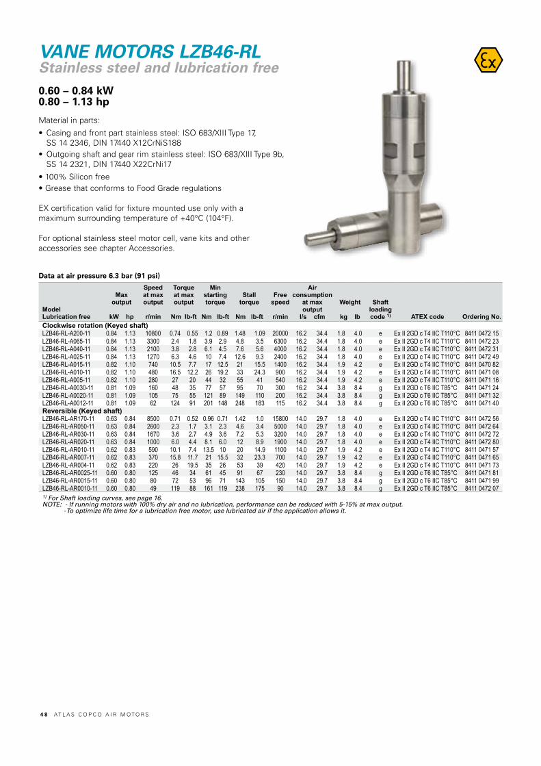
ModelLubrication free
Maxoutput
kW hp
Speedat maxoutput
r/min
Torqueat maxoutput
Nm lb-ft
Minstartingtorque
Nm lb-ft
Stalltorque
Nm lb-ft
Free speed
r/min
Airconsumption
at maxoutput
l/s cfm
Weight
kg lb
Shaft loadingcode 1) ATEX code Ordering No.
Clockwise rotation (Keyed shaft) LZB46-RL-A200-11 0.84 1.13 10800 0.74 0.55 1.2 0.89 1.48 1.09 20000 16.2 34.4 1.8 4.0 e Ex II 2GD c T4 IIC T110°C 8411 0472 15LZB46-RL-A065-11 0.84 1.13 3300 2.4 1.8 3.9 2.9 4.8 3.5 6300 16.2 34.4 1.8 4.0 e Ex II 2GD c T4 IIC T110°C 8411 0472 23LZB46-RL-A040-11 0.84 1.13 2100 3.8 2.8 6.1 4.5 7.6 5.6 4000 16.2 34.4 1.8 4.0 e Ex II 2GD c T4 IIC T110°C 8411 0472 31LZB46-RL-A025-11 0.84 1.13 1270 6.3 4.6 10 7.4 12.6 9.3 2400 16.2 34.4 1.8 4.0 e Ex II 2GD c T4 IIC T110°C 8411 0472 49LZB46-RL-A015-11 0.82 1.10 740 10.5 7.7 17 12.5 21 15.5 1400 16.2 34.4 1.9 4.2 e Ex II 2GD c T4 IIC T110°C 8411 0470 82LZB46-RL-A010-11 0.82 1.10 480 16.5 12.2 26 19.2 33 24.3 900 16.2 34.4 1.9 4.2 e Ex II 2GD c T4 IIC T110°C 8411 0471 08LZB46-RL-A005-11 0.82 1.10 280 27 20 44 32 55 41 540 16.2 34.4 1.9 4.2 e Ex II 2GD c T4 IIC T110°C 8411 0471 16LZB46-RL-A0030-11 0.81 1.09 160 48 35 77 57 95 70 300 16.2 34.4 3.8 8.4 g Ex II 2GD c T6 IIC T85°C 8411 0471 24LZB46-RL-A0020-11 0.81 1.09 105 75 55 121 89 149 110 200 16.2 34.4 3.8 8.4 g Ex II 2GD c T6 IIC T85°C 8411 0471 32LZB46-RL-A0012-11 0.81 1.09 62 124 91 201 148 248 183 115 16.2 34.4 3.8 8.4 g Ex II 2GD c T6 IIC T85°C 8411 0471 40Reversible (Keyed shaft)LZB46-RL-AR170-11 0.63 0.84 8500 0.71 0.52 0.96 0.71 1.42 1.0 15800 14.0 29.7 1.8 4.0 e Ex II 2GD c T4 IIC T110°C 8411 0472 56LZB46-RL-AR050-11 0.63 0.84 2600 2.3 1.7 3.1 2.3 4.6 3.4 5000 14.0 29.7 1.8 4.0 e Ex II 2GD c T4 IIC T110°C 8411 0472 64LZB46-RL-AR030-11 0.63 0.84 1670 3.6 2.7 4.9 3.6 7.2 5.3 3200 14.0 29.7 1.8 4.0 e Ex II 2GD c T4 IIC T110°C 8411 0472 72LZB46-RL-AR020-11 0.63 0.84 1000 6.0 4.4 8.1 6.0 12 8.9 1900 14.0 29.7 1.8 4.0 e Ex II 2GD c T4 IIC T110°C 8411 0472 80LZB46-RL-AR010-11 0.62 0.83 590 10.1 7.4 13.5 10 20 14.9 1100 14.0 29.7 1.9 4.2 e Ex II 2GD c T4 IIC T110°C 8411 0471 57LZB46-RL-AR007-11 0.62 0.83 370 15.8 11.7 21 15.5 32 23.3 700 14.0 29.7 1.9 4.2 e Ex II 2GD c T4 IIC T110°C 8411 0471 65LZB46-RL-AR004-11 0.62 0.83 220 26 19.5 35 26 53 39 420 14.0 29.7 1.9 4.2 e Ex II 2GD c T4 IIC T110°C 8411 0471 73LZB46-RL-AR0025-11 0.60 0.80 125 46 34 61 45 91 67 230 14.0 29.7 3.8 8.4 g Ex II 2GD c T6 IIC T85°C 8411 0471 81LZB46-RL-AR0015-11 0.60 0.80 80 72 53 96 71 143 105 150 14.0 29.7 3.8 8.4 g Ex II 2GD c T6 IIC T85°C 8411 0471 99LZB46-RL-AR0010-11 0.60 0.80 49 119 88 161 119 238 175 90 14.0 29.7 3.8 8.4 g Ex II 2GD c T6 IIC T85°C 8411 0472 071) For Shaft loading curves, see page 16. NOTE: - If running motors with 100% dry air and no lubrication, performance can be reduced with 5-15% at max output. - To optimize life time for a lubrication free motor, use lubricated air if the application allows it.
VANE MOTORS LZB46-RLStainless steel and lubrication free0.60 – 0.84 kW0.80 – 1.13 hp
Material in parts:
• Casing and front part stainless steel: ISO 683/XIII Type 17, SS 14 2346, DIN 17440 X12CrNiS188 • Outgoing shaft and gear rim stainless steel: ISO 683/XIII Type 9b, SS 14 2321, DIN 17440 X22CrNi17
• 100% Silicon free• Grease that conforms to Food Grade regulations
EX certification valid for fixture mounted use only with a maximum surrounding temperature of +40°C (104°F).
For optional stainless steel motor cell, vane kits and otheraccessories see chapter Accessories.
Data at air pressure 6.3 bar (91 psi)
4 8 AT L A S C O P C O A I R M O T O R S

LZ
B V
AN
E M
OT
OR
S
Dimensions (mm) Conversion factor 1 mm = 0.04 inch
Clockwise Reversible
LZB46-RL-A200 LZB46-RL-AR170 LZB46-RL-A065 LZB46-RL-AR050 LZB46-RL-A040 LZB46-RL-AR030 LZB46-RL-A025 LZB46-RL-AR020 LZB46-RL-A015 LZB46-RL-AR010 LZB46-RL-A010 LZB46-RL-AR007 LZB46-RL-A005 LZB46-RL-AR004
All versions
Ø16
j6
5 h7
18
A/F 41
10.6
BSP 1/4”
BSP 1/2”
10.5
10
10
Ø17
M5
42
40
4
THREAD DEPTH 15 mm
218
30
176
A/F
41
Ø46
BSP 1/4”
BSP 1/2”A/F 41
10.5
14.3
Ø30
M5
5
44
40
30
THREAD DEPTH 15mm
263.5
28 86
Ø46
A/F
55
Ø60
Ø19
j6
6 h7
21.5
42 3
Ø60
h8
14
118
5050
35Ø10.3
26Ø8.3
4040
96
39 2
Ø45
h8
10
60
M6
10
80
44
R30
3061.2
3820
47.2
10
50
60
M5
R23
Ø16
j6
5 h7
18
A/F 41
10.6
BSP 1/4”
BSP 1/2”
10.5
10
10
Ø17
M5
42
40
4
THREAD DEPTH 15 mm
218
30
176
A/F
41
Ø46
BSP 1/4”
BSP 1/2”A/F 41
10.5
14.3
Ø30
M5
5
44
40
30
THREAD DEPTH 15mm
263.5
28 86
Ø46
A/F
55
Ø60
Ø19
j6
6 h7
21.5
42 3
Ø60
h8
14
118
5050
35Ø10.3
26Ø8.3
4040
96
39 2
Ø45
h8
10
60
M6
10
80
44
R30
3061.2
38
20
47.2
10
50
60
M5
R23
Ø16
j6
5 h7
18
A/F 41
10.6
BSP 1/4”
BSP 1/2”
10.5
10
10
Ø17
M5
42
40
4
THREAD DEPTH 15 mm
218
30
176
A/F
41
Ø46
BSP 1/4”
BSP 1/2”A/F 41
10.5
14.3
Ø30
M5
5
44
40
30
THREAD DEPTH 15mm
263.5
28 86Ø
46
A/F
55
Ø60
Ø19
j6
6 h7
21.5
42 3
Ø60
h8
14
118
5050
35Ø10.3
26Ø8.3
4040
96
39 2
Ø45
h8
10
60
M6
10
80
44
R30
3061.2
38
20
47.2
10
50
60
M5
R23
Ø16
j6
5 h7
18
A/F 41
10.6
BSP 1/4”
BSP 1/2”
10.5
10
10
Ø17
M5
42
40
4
THREAD DEPTH 15 mm
218
30
176
A/F
41
Ø46
BSP 1/4”
BSP 1/2”A/F 41
10.5
14.3
Ø30
M5
5
44
40
30
THREAD DEPTH 15mm
263.5
28 86
Ø46
A/F
55
Ø60
Ø19
j6
6 h7
21.5
42 3
Ø60
h8
14
118
5050
35Ø10.3
26Ø8.3
4040
96
39 2
Ø45
h8
10
60
M6
10
80
44
R30
3061.2
38
20
47.2
10
50
60
M5
R23
Reversible
Clockwise/Anti-clockwise
AluminiumFlange Ordering No. 4430 0490 81
AluminiumFlange Ordering No. 4430 0569 84
Foot Ordering No. 4430 0575 81
Foot Ordering No. 4430 0178 81
Keyed shaft (-11)
Keyed shaft (-11)
Optional mountings
Optional mountings
ClockwiseLZB46-RL-A0030 LZB46-RL-A0020 LZB46-RL-A0012
ReversibleLZB46-RL-AR0025 LZB46-RL-AR0015 LZB46-RL-AR0010
Ø10.3
118
50
50
8
3
4735
Ø 6
0 h8
A
40
40
96
28
6
244.2
Ø 4
5 h8
Ø 8.3
Stainless steelFlange Ordering No. 4430 1483 80
Stainless steelFlange Ordering No. 4430 2357 80
AT L A S C O P C O A I R M O T O R S 4 9
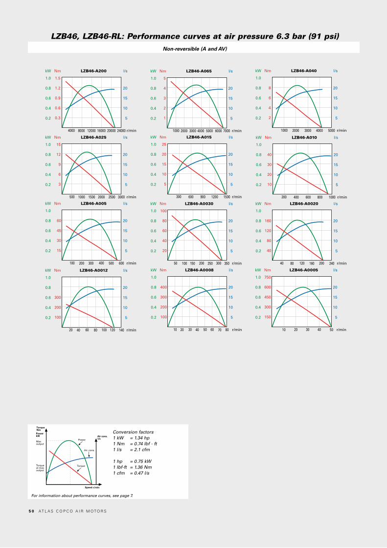
Nm LZB46-A200 l/s
r/min
kW
4000 8000 12000 16000 20000 24000
20
15
10
5
1.5
1.2
0.9
0.6
0.3
1.0
0.8
0.6
0.4
0.2
Nm LZB46-A065 l/s
r/min
kW
1000 2000 3000 4000 5000 7000
20
15
10
5
5
4
3
2
1
1.0
0.8
0.6
0.4
0.2
6000
Nm LZB46-A040 l/s
r/min
kW
1000 2000 3000 5000
20
15
10
5
8
6
4
2
1.0
0.8
0.6
0.4
0.2
4000
Nm LZB46-A025 l/s
r/min
kW
500 1000 1500 3000
20
15
10
5
15
12
9
6
3
1.0
0.8
0.6
0.4
0.2
2000 2500
Nm LZB46-A015 l/s
r/min
kW
300 600 1500
20
15
10
5
25
20
15
10
5
1.0
0.8
0.6
0.4
0.2
900 1200
Nm LZB46-A010 l/s
r/min
kW
200 400 1000
20
15
10
5
40
30
20
10
1.0
0.8
0.6
0.4
0.2
600 800
Nm LZB46-A005 l/s
r/min
kW
100 200 600
20
15
10
5
60
45
30
15
1.0
0.8
0.6
0.4
0.2
300 500400
Nm LZB46-A0030 l/s
r/min
kW
50 100 350
20
15
10
5
100
80
60
40
20
1.0
0.8
0.6
0.4
0.2
150 250200 300
Nm LZB46-A0020 l/s
r/min
kW
40 80 240
20
15
10
5
160
120
80
40
1.0
0.8
0.6
0.4
0.2
160120 200
Nm LZB46-A0012 l/s
r/min
kW
20 40 140
20
15
10
5
300
200
100
1.0
0.8
0.6
0.4
0.2
8060 100 120
Nm LZB46-A0008 l/s
r/min
kW
10 20 80
20
15
10
5
400
300
200
100
1.0
0.8
0.6
0.4
0.2
4030 50 60 70
Nm LZB46-A0005 l/s
r/min
kW
10 50
20
15
10
5
750
600
450
300
150
1.0
0.8
0.6
0.4
0.2
20 30 40
LZB46, LZB46-RL: Performance curves at air pressure 6.3 bar (91 psi)Non-reversible (A and AV)
Conversion factors1 kW = 1.34 hp1 Nm = 0.74 Ibf - ft1 l/s = 2.1 cfm
1 hp = 0.75 kW1 Ibf-ft = 1.36 Nm1 cfm = 0.47 l/s
TorqueNmPowerkW
Maxoutput
Torqueat maxoutput
Torque
Power
Speed r/min
Air. cons.
Air cons.l/s
For information about performance curves, see page 7.
5 0 AT L A S C O P C O A I R M O T O R S
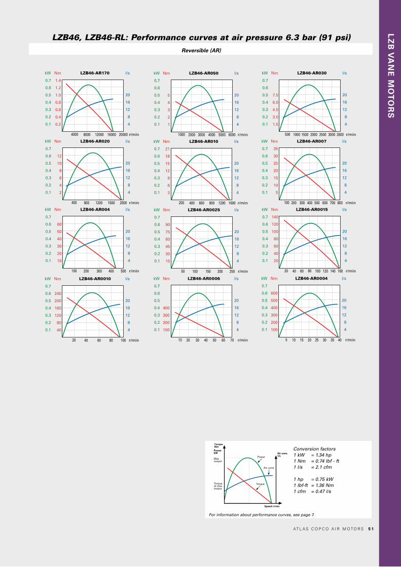
Nm LZB46-AR170 l/s
r/min
kW
4000 8000 12000 16000 20000
20
16
12
8
4
1.4
1.2
1.0
0.8
0.6
0.4
0.2
0.7
0.6
0.5
0.4
0.3
0.2
0.1
Nm LZB46-AR050 l/s
r/min
kW
1000 2000 3000 4000 5000
20
16
12
8
4
5
4
3
2
1
0.7
0.6
0.5
0.4
0.3
0.2
0.1
6000
Nm LZB46-AR030 l/s
r/min
kW
500 1000 1500 2000 2500
20
16
12
8
4
7.5
6.0
4.5
3.0
1.5
0.7
0.6
0.5
0.4
0.3
0.2
0.1
35003000
Nm LZB46-AR020 l/s
r/min
kW
400 800 1200 1600
20
16
12
8
4
12
10
8
6
4
2
0.7
0.6
0.5
0.4
0.3
0.2
0.1
2000
Nm LZB46-AR010 l/s
r/min
kW
200 400 600 800
20
16
12
8
4
21
18
15
12
9
6
3
0.7
0.6
0.5
0.4
0.3
0.2
0.1
16001200
Nm LZB46-AR007 l/s
r/min
kW
100 200 300 400
20
16
12
8
4
35
30
25
20
15
10
5
0.7
0.6
0.5
0.4
0.3
0.2
0.1
800500 600 700
Nm LZB46-AR004 l/s
r/min
kW
100 200 300
20
16
12
8
4
60
50
40
30
20
10
0.7
0.6
0.5
0.4
0.3
0.2
0.1
500400
Nm LZB46-AR0025 l/s
r/min
kW
50 100 150
20
16
12
8
4
90
75
60
45
30
15
0.7
0.6
0.5
0.4
0.3
0.2
0.1
250200
Nm LZB46-AR0010 l/s
r/min
kW
20 40 60
20
16
12
8
4
240
200
160
120
80
40
0.7
0.6
0.5
0.4
0.3
0.2
0.1
10080
Nm LZB46-AR0015 l/s
r/min
kW
20 40 60
20
16
12
8
4
140
120
100
80
60
40
20
0.7
0.6
0.5
0.4
0.3
0.2
0.1
16014080 100 120
Nm LZB46-AR0006 l/s
r/min
kW
10 20 40
20
16
12
8
4
400
300
200
100
0.7
0.6
0.5
0.4
0.3
0.2
0.1
705030 60
Nm LZB46-AR0004 l/s
r/min
kW
5 10 20
20
16
12
8
4
600
500
400
300
200
100
0.7
0.6
0.5
0.4
0.3
0.2
0.1
402515 3530
LZB46, LZB46-RL: Performance curves at air pressure 6.3 bar (91 psi)Reversible (AR)
LZ
B V
AN
E M
OT
OR
S
Conversion factors1 kW = 1.34 hp1 Nm = 0.74 Ibf - ft1 l/s = 2.1 cfm
1 hp = 0.75 kW1 Ibf-ft = 1.36 Nm1 cfm = 0.47 l/s
TorqueNmPowerkW
Maxoutput
Torqueat maxoutput
Torque
Power
Speed r/min
Air. cons.
Air cons.l/s
For information about performance curves, see page 7.
AT L A S C O P C O A I R M O T O R S 5 1

VANE MOTORS LZB540.79 – 1.20 kW1.06 – 1.61 hp
EX certification valid for fixture mounted use only with a maximum surrounding temperature of +40°C (104°F).
For optional vanes and accessories see chapter Accessories.
ModelLubricated
Maxoutput
kW hp
Speedat maxoutput
r/min
Torqueat maxoutput
Nm lb-ft
Minstartingtorque
Nm lb-ft
Stalltorque
Nm lb-ft
Free speed
r/min
Airconsump-tion at max
outputl/s cfm
Weight
kg lb
Shaft loadingcode 1) ATEX code Ordering No.
Clockwise rotation (Keyed shaft) LZB54-A180-11 1.20 1.61 10000 1.15 0.85 1.8 1.33 2.3 1.7 17500 22.0 47.0 2.4 5.2 g Ex II 2GD c T4 IIC T110°C 8411 0560 08LZB54-A050-11 1.20 1.61 2900 4.0 3.0 6.4 4.7 8.0 5.9 5100 22.0 47.0 2.4 5.2 g Ex II 2GD c T4 IIC T110°C 8411 0560 16LZB54-A030-11 1.20 1.61 1750 6.6 4.9 10.5 7.7 13.2 9.7 3100 22.0 47.0 2.4 5.2 g Ex II 2GD c T4 IIC T110°C 8411 0560 24LZB54-A020-11 1.20 1.61 1300 8.9 6.6 14 10.3 17.8 13.1 2300 22.0 47.0 2.4 5.2 g Ex II 2GD c T4 IIC T110°C 8411 0560 32LZB54-A010-11 1.18 1.58 630 18 13.3 29 21 36 27 1050 22.0 47.0 2.5 5.5 g Ex II 2GD c T6 IIC T85°C 8411 0560 40LZB54-A007-11 1.18 1.58 380 30 22 48 35 60 44 650 22.0 47.0 2.5 5.5 g Ex II 2GD c T6 IIC T85°C 8411 0560 57LZB54-A005-11 1.18 1.58 280 40 30 65 48 80 59 500 22.0 47.0 2.5 5.5 g Ex II 2GD c T6 IIC T85°C 8411 0560 65LZB54-A0025-11 1.15 1.54 150 72 53 117 86 144 106 270 22.0 47.0 4.7 10.3 h Ex II 2GD c T6 IIC T85°C 8411 0560 73LZB54-A0017-11 1.15 1.54 95 119 88 193 142 238 176 160 22.0 47.0 4.7 10.3 h Ex II 2GD c T6 IIC T85°C 8411 0560 81LZB54-A0012-11 1.15 1.54 70 161 119 261 193 322 237 120 22.0 47.0 4.7 10.3 h Ex II 2GD c T6 IIC T85°C 8411 0560 99Anti-clockwise rotation (Keyed shaft)LZB54-AV180-11 1.20 1.61 10000 1.15 0.85 1.8 1.33 2.3 1.7 17500 22.0 47.0 2.4 5.2 g Ex II 2GD c T4 IIC T110°C 8411 0564 04LZB54-AV050-11 1.20 1.61 2900 4.0 3.0 6.4 4.7 8.0 5.9 5100 22.0 47.0 2.4 5.2 g Ex II 2GD c T4 IIC T110°C 8411 0564 12LZB54-AV030-11 1.20 1.61 1750 6.6 4.9 10.5 7.7 13.2 9.7 3100 22.0 47.0 2.4 5.2 g Ex II 2GD c T4 IIC T110°C 8411 0564 20LZB54-AV020-11 1.20 1.61 1300 8.9 6.6 14 10.3 17.8 13.1 2300 22.0 47.0 2.4 5.2 g Ex II 2GD c T4 IIC T110°C 8411 0564 38LZB54-AV010-11 1.18 1.58 630 18 13.3 29 21 36 27 1050 22.0 47.0 2.5 5.5 g Ex II 2GD c T6 IIC T85°C 8411 0564 46LZB54-AV007-11 1.18 1.58 380 30 22 48 35 60 44 650 22.0 47.0 2.5 5.5 g Ex II 2GD c T6 IIC T85°C 8411 0564 53LZB54-AV005-11 1.18 1.58 280 40 30 65 48 80 59 500 22.0 47.0 2.5 5.5 g Ex II 2GD c T6 IIC T85°C 8411 0564 61LZB54-AV0025-11 1.15 1.54 150 72 53 117 86 144 106 270 22.0 47.0 4.7 10.3 h Ex II 2GD c T6 IIC T85°C 8411 0564 79LZB54-AV0017-11 1.15 1.54 95 119 88 193 142 238 176 160 22.0 47.0 4.7 10.3 h Ex II 2GD c T6 IIC T85°C 8411 0564 87LZB54-AV0012-11 1.15 1.54 70 161 119 261 193 322 237 120 22.0 47.0 4.7 10.3 h Ex II 2GD c T6 IIC T85°C 8411 0564 95Reversible (Keyed shaft)LZB54-AR130-11 0.82 1.10 6800 1.15 0.85 1.4 1.03 2.3 1.7 12000 18.0 38.0 2.4 5.2 g Ex II 2GD c T4 IIC T110°C 8411 0563 05LZB54-AR035-11 0.82 1.10 1960 4.0 3.0 5.1 3.8 8.0 5.9 3700 18.0 38.0 2.4 5.2 g Ex II 2GD c T4 IIC T110°C 8411 0563 13LZB54-AR020-11 0.82 1.10 1190 6.6 4.9 8.4 6.2 13.2 9.7 2300 18.0 38.0 2.4 5.2 g Ex II 2GD c T4 IIC T110°C 8411 0563 21LZB54-AR015-11 0.82 1.10 880 8.9 6.6 11 8.1 17.8 13.1 1700 18.0 38.0 2.4 5.2 g Ex II 2GD c T4 IIC T110°C 8411 0563 39LZB54-AR008-11 0.80 1.07 430 18 13.3 23 17 36 27 800 18.0 38.0 2.5 5.5 g Ex II 2GD c T6 IIC T85°C 8411 0563 47LZB54-AR005-11 0.80 1.07 260 30 22 38 28 60 44 500 18.0 38.0 2.5 5.5 g Ex II 2GD c T6 IIC T85°C 8411 0563 54LZB54-AR004-11 0.80 1.07 190 40 30 51 38 80 59 370 18.0 38.0 2.5 5.5 g Ex II 2GD c T6 IIC T85°C 8411 0563 62LZB54-AR0020-11 0.79 1.06 105 72 53 93 69 144 106 190 18.0 38.0 4.7 10.3 h Ex II 2GD c T6 IIC T85°C 8411 0563 70LZB54-AR0012-11 0.79 1.06 65 119 88 153 113 238 176 120 18.0 38.0 4.7 10.3 h Ex II 2GD c T6 IIC T85°C 8411 0563 88LZB54-AR0009-11 0.79 1.06 47 161 119 207 153 322 237 90 18.0 38.0 4.7 10.3 h Ex II 2GD c T6 IIC T85°C 8411 0563 961) For Shaft loading curves, see page 16.
Data at air pressure 6.3 bar (91 psi)
5 2 AT L A S C O P C O A I R M O T O R S
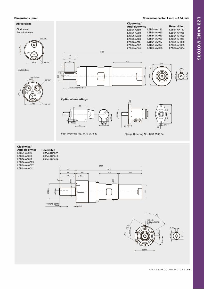
LZ
B V
AN
E M
OT
OR
S
Dimensions (mm) Conversion factor 1 mm = 0.04 inch
Ø28
j6
8 h7
31
A/F
75
Ø83 h9
M8 (x6)THREAD DEPTH18mm
6 P
9
R36
.5
Ø19
j6
6 h7
21.5
15
BSP 3/8”
BSP 1/2”
11
13.5
A/F 50
13.5
Ø30
M5
44
40
5
THREAD DEPTH 15mm
30
243.5
89.5
Ø56
Ø60
A/F
55
BSP 3/8”
A/F 50 BSP 1/2”
1516
313.5
74.8 89.548.2
25
62
60
50
251.5
5
Ø62
K6
Ø30
M10
2.7THREAD DEPTH
24mm
Ø60
Ø5
6
42 3
Ø60
h8
14
118
5050
35Ø10.3
44
61.230
R30
60
M6
10
80
Clockwise/Anti-clockwise
All versions
Ø28
j6
8 h7
31
A/F
75
Ø83 h9
M8 (x6)THREAD DEPTH18mm
6 P
9
R36
.5
Ø19
j6
6 h7
21.5
15
BSP 3/8”
BSP 1/2”
11
13.5
A/F 50
13.5
Ø30
M5
44
40
5
THREAD DEPTH 15mm
30
243.5
89.5
Ø56
Ø60
A/F
55
BSP 3/8”
A/F 50 BSP 1/2”
1516
313.5
74.8 89.548.2
25
62
60
50
251.5
5
Ø62
K6
Ø30
M10
2.7THREAD DEPTH
24mm
Ø60
Ø5
6
42 3
Ø60
h8
14
118
5050
35Ø10.3
44
61.230
R30
60
M6
10
80
Ø28
j6
8 h7
31
A/F
75
Ø83 h9
M8 (x6)THREAD DEPTH18mm
6 P
9
R36
.5
Ø19
j6
6 h7
21.5
15
BSP 3/8”
BSP 1/2”
11
13.5
A/F 50
13.5
Ø30
M5
44
40
5
THREAD DEPTH 15mm
30
243.5
89.5
Ø56
Ø60
A/F
55
BSP 3/8”
A/F 50 BSP 1/2”
1516
313.5
74.8 89.548.2
25
62
60
50
251.5
5
Ø62
K6
Ø30
M10
2.7THREAD DEPTH
24mm
Ø60
Ø5
6
42 3Ø
60 h
8
14
118
5050
35Ø10.3
44
61.230
R30
60
M6
10
80
Ø28
j6
8 h7
31
A/F
75
Ø83 h9
M8 (x6)THREAD DEPTH18mm
6 P
9
R36
.5
Ø19
j6
6 h7
21.5
15
BSP 3/8”
BSP 1/2”
11
13.5
A/F 50
13.5
Ø30
M5
44
40
5
THREAD DEPTH 15mm
30
243.5
89.5
Ø56
Ø60
A/F
55
BSP 3/8”
A/F 50 BSP 1/2”
1516
313.5
74.8 89.548.2
25
62
60
50
251.5
5
Ø62
K6
Ø30
M10
2.7THREAD DEPTH
24mm
Ø60
Ø5
6
42 3
Ø60
h8
14
118
5050
35Ø10.3
44
61.230
R30
60
M6
10
80
Reversible
Optional mountings
Clockwise/Anti-clockwiseLZB54-A0025 LZB54-A0017 LZB54-A0012 LZB54-AV0025 LZB54-AV0017 LZB54-AV0012
ReversibleLZB54-AR0020 LZB54-AR0012 LZB54-AR0009
Flange Ordering No. 4430 0569 84Foot Ordering No. 4430 0178 80
Clockwise/Anti-clockwiseLZB54-A180 LZB54-A050 LZB54-A030 LZB54-A020 LZB54-A010 LZB54-A007 LZB54-A005
LZB54-AV180 LZB54-AV050 LZB54-AV030 LZB54-AV020 LZB54-AV010 LZB54-AV007 LZB54-AV005
ReversibleLZB54-AR130 LZB54-AR035 LZB54-AR020 LZB54-AR015 LZB54-AR008 LZB54-AR005 LZB54-AR004
AT L A S C O P C O A I R M O T O R S 5 3

VANE MOTORS LZB54-LB Brake module, lubrication free and reversible0.79 – 0.82 kW1.05 – 1.10 hp
Braking torque from 15–200 Nm.The brake is activated by spring force and released by air pressure.
EX certification valid for fixture mounted use only with a maximum surrounding temperature of +40°C (104°F).
For optional vanes and accessories see chapter Accessories.
Model Lubrication free
Maxoutput
kW hp
Speedat maxoutput
r/min
Torqueat maxoutput
Nm lb-ft
Minstarting torque
Nm lb-ft
Stalltorque
Nm lb-ft
Braking torque
Nm lb-ft
Free speed
r/min
Airconsump-tion at max
outputl/s cfm
Weight
kg lb
Shaft loading code 1) ATEX code Ordering No.
Reversible (Keyed shaft)LZB54-LB-AR015-11 0.82 1.1 880 8.9 6.6 11 8.1 17.8 13.1 15 11 1700 18 38 4.1 9 g Ex II 2GD c T4 IIC T110°C 8411 0568 42LZB54-LB-AR005-11 0.8 1.07 260 30 22 38 28 60 44 50 37 500 18 38 4.3 9.4 g Ex II 2GD c T6 IIC T85°C 8411 0568 59LZB54-LB-AR004-11 0.8 1.07 190 40 30 51 38 80 59 70 52 370 18 38 4.3 9.4 g Ex II 2GD c T6 IIC T85°C 8411 0568 67LZB54-LB-AR0020-11 0.79 1.06 105 72 53 93 69 144 106 125 92.5 190 18 38 6.4 14 h Ex II 2GD c T6 IIC T85°C 8411 0568 75LZB54-LB-AR0012-11 0.79 1.06 65 119 88 153 113 238 176 200 148 120 18 38 6.4 14 h Ex II 2GD c T6 IIC T85°C 8411 0568 83LZB54-LB-AR0009-11 0.79 1.06 47 161 119 207 153 322 237 280 206 90 18 38 6.4 14 h Ex II 2GD c T6 IIC T85°C 8411 0569 101) For Shaft loading curves, see page 16.The brake needs minimum 5 bar to release. Performance curves same as standard motors.NOTE: - If running motors with 100% dry air and no lubrication, performance can be reduced with 5-15% at max output. - To optimize life time for a lubrication free motor, use lubricated air if the application allows it.
Data at air pressure 6.3 bar (91 psi)
5 4 AT L A S C O P C O A I R M O T O R S

LZ
B V
AN
E M
OT
OR
S
Dimensions (mm) Conversion factor 1 mm = 0.04 inch
Ø28
j6
8 h7
31
15
BSP 3/8”
BSP 1/2”
11
13.5
A/F 50
13.5
A/F
70
Ø30
M10
62
60
5
THREAD DEPTH24mm
50
Ø62
K6
2.7
25
48.2
393.5
331.5
154.8 89.5
128 19
Ø56
R36
.5
A/F
75
Ø83 h9
M8 (x6)THREAD DEPTH18mm
6 P
9
13.5
74
13.5
1115
A/F 50
BSP 3/8”
BSP 1/2”
Ø19
j6
6 h7
21.5
Ø30
5
M5
44
40
30
THREAD DEPTH 15mm
324
280
128
89.5
19
Ø56
A/F
55
Ø60
42 3
Ø60
h8
14
118
5050
35Ø10.3
44
61.2
R30
60
M6
10
80
30
Reversible
Reversible with brakeLZB54-LB-AR015 LZB54-LB-AR005 LZB54-LB-AR004
Reversible with brakeLZB54-LB-AR0020 LZB54-LB-AR0012LZB54-LB-AR0009
Optional mountings
Flange Ordering No. 4430 0569 84Foot Ordering No. 4430 0178 80
AT L A S C O P C O A I R M O T O R S 5 5

Nm LZB54-A180 l/s
r/min
kW
4000 8000 12000 16000 20000
30
25
20
15
10
5
2.8
2.4
2.0
1.6
1.2
0.8
0.4
1.4
1.2
1.0
0.8
0.6
0.4
0.2
Nm LZB54-A050 l/s
r/min
kW
1000 2000 3000 4000 6000
30
25
20
15
10
5
9.0
7.5
6.0
4.5
3.0
1.5
1.4
1.2
1.0
0.8
0.6
0.4
0.2
5000
Nm LZB54-A030 l/s
r/min
kW
500 1000 1500 2000 3500
30
25
20
15
10
5
14
12
10
8
6
4
2
1.4
1.2
1.0
0.8
0.6
0.4
0.2
2500 3000
Nm LZB54-A020 l/s
r/min
kW
400 800 1200 1600 2400
30
25
20
15
10
5
21
18
15
12
9
6
3
1.4
1.2
1.0
0.8
0.6
0.4
0.2
2000
Nm LZB54-A010 l/s
r/min
kW
200 400 600 800 1200
30
25
20
15
10
5
40
30
20
10
1.4
1.2
1.0
0.8
0.6
0.4
0.2
1000
Nm LZB54-A007 l/s
r/min
kW
100 200 300 400 700
30
25
20
15
10
5
70
60
50
40
30
20
10
1.4
1.2
1.0
0.8
0.6
0.4
0.2
500 600
Nm LZB54-A005 l/s
r/min
kW
100 200 300 400 500
30
25
20
15
10
5
90
75
60
45
30
15
1.4
1.2
1.0
0.8
0.6
0.4
0.2
Nm LZB54-A0025 l/s
r/min
kW
50 100 150 200 300
30
25
20
15
10
5
180
150
120
90
60
30
1.4
1.2
1.0
0.8
0.6
0.4
0.2
250
Nm LZB54-A0017 l/s
r/min
kW
40 80 120 160 200
30
25
20
15
10
5
280
240
200
160
120
80
40
1.4
1.2
1.0
0.8
0.6
0.4
0.2
Nm LZB54-A0012 l/s
r/min
kW
20 40 60 80 140
30
25
20
15
10
5
350
300
250
200
150
100
50
1.4
1.2
1.0
0.8
0.6
0.4
0.2
100 120
LZB54: Performance curves at air pressure 6.3 bar (91 psi)Non-reversible (A and AV)
Conversion factors1 kW = 1.34 hp1 Nm = 0.74 Ibf - ft1 l/s = 2.1 cfm
1 hp = 0.75 kW1 Ibf-ft = 1.36 Nm1 cfm = 0.47 l/s
TorqueNmPowerkW
Maxoutput
Torqueat maxoutput
Torque
Power
Speed r/min
Air. cons.
Air cons.l/s
For information about performance curves, see page 7.
5 6 AT L A S C O P C O A I R M O T O R S

Nm LZB54-AR130 l/s
r/min
kW
4000 8000
30
20
10
2.5
2.0
1.5
1.0
0.5
1.0
0.8
0.6
0.4
0.2
12000
Nm LZB54-AR035 l/s
r/min
kW
1000 2000
30
20
10
8
6
4
2
1.0
0.8
0.6
0.4
0.2
3000 4000
Nm LZB54-AR020 l/s
r/min
kW
400 800
30
20
10
15
12
9
6
3
1.0
0.8
0.6
0.4
0.2
1200 24001600 2000
Nm LZB54-AR015 l/s
r/min
kW
400 800
30
20
10
20
16
12
8
4
1.0
0.8
0.6
0.4
0.2
20001200 1600
Nm LZB54-AR008 l/s
r/min
kW
200 400
30
20
10
40
30
20
10
1.0
0.8
0.6
0.4
0.2
1000600 800
Nm LZB54-AR005 l/s
r/min
kW
100 200
30
20
10
60
45
30
15
1.0
0.8
0.6
0.4
0.2
500300 400
Nm LZB54-AR004 l/s
r/min
kW
50 200
30
20
10
80
60
40
20
1.0
0.8
0.6
0.4
0.2
300 400100 150 250 350
Nm LZB54-AR0020 l/s
r/min
kW
40 80
30
20
10
150
120
90
60
30
1.0
0.8
0.6
0.4
0.2
120 240160 200
Nm LZB54-AR0012 l/s
r/min
kW
40 80
30
20
10
250
200
150
100
50
1.0
0.8
0.6
0.4
0.2
12020 60 100 140
Nm LZB54-AR0009 l/s
r/min
kW
20 40
30
20
10
400
300
200
100
1.0
0.8
0.6
0.4
0.2
10060 80
LZB54: Performance curves at air pressure 6.3 bar (91 psi)Reversible (AR)
LZ
B V
AN
E M
OT
OR
S
Conversion factors1 kW = 1.34 hp1 Nm = 0.74 Ibf - ft1 l/s = 2.1 cfm
1 hp = 0.75 kW1 Ibf-ft = 1.36 Nm1 cfm = 0.47 l/s
TorqueNmPowerkW
Maxoutput
Torqueat maxoutput
Torque
Power
Speed r/min
Air. cons.
Air cons.l/s
For information about performance curves, see page 7.
AT L A S C O P C O A I R M O T O R S 5 7

VANE MOTORS LZB661.41 – 1.87 kW1.89 – 2.51 hp
EX certification valid for fixture mounted use only with a maximum surrounding temperature of +40°C (104°F).
For optional vanes and accessories see chapter Accessories.
ModelLubricated
Maxoutput
kW hp
Speedat maxoutput
r/min
Torqueat maxoutput
Nm lb-ft
Minstartingtorque
Nm lb-ft
Stalltorque
Nm lb-ft
Free speed
r/min
Airconsumption
at maxoutput
l/s cfm
Weight
kg lb
Shaft loadingcode 1) ATEX code Ordering No.
Clockwise rotation (Keyed shaft) LZB66-A180-11 1.87 2.51 8200 2.2 1.62 3.2 2.4 4.4 3.2 16000 34 72 2.8 6.2 g Ex II 2GD c T4 IIC T110°C 8411 0602 59LZB66-A050-11 1.87 2.51 2400 7.6 5.6 11.3 8.3 15.2 11.2 4500 34 72 2.8 6.2 g Ex II 2GD c T4 IIC T110°C 8411 0602 67LZB66-A030-11 1.87 2.51 1440 12.5 9.2 18.6 13.7 25 18.4 2700 34 72 2.8 6.2 g Ex II 2GD c T4 IIC T110°C 8411 0602 75LZB66-A020-11 1.87 2.51 1060 17 12.5 25 18.4 34 25 2000 34 72 2.8 6.2 g Ex II 2GD c T4 IIC T110°C 8411 0602 42LZB66-A010-11 1.83 2.45 510 34 25 51 38 68 50 950 34 72 2.9 6.4 g Ex II 2GD c T6 IIC T85°C 8411 0600 59LZB66-A007-11 1.83 2.45 310 57 42 84 62 114 84 600 34 72 2.9 6.4 g Ex II 2GD c T6 IIC T85°C 8411 0600 67LZB66-A005-11 1.83 2.45 230 77 57 113 83 154 114 440 34 72 2.9 6.4 g Ex II 2GD c T6 IIC T85°C 8411 0600 75LZB66-A0025-11 1.80 2.41 125 139 103 205 151 278 205 230 34 72 5.1 11.1 h Ex II 2GD c T6 IIC T85°C 8411 0600 83LZB66-A0017-11 1.80 2.41 75 227 167 337 249 454 335 145 34 72 5.1 11.1 h Ex II 2GD c T6 IIC T85°C 8411 0600 91LZB66-A0012-11 1.80 2.41 55 308 227 456 336 616 454 110 34 72 5.1 11.1 h Ex II 2GD c T6 IIC T85°C 8411 0602 83Reversible (Keyed shaft)LZB66-AR130-11 1.46 1.96 7500 1.9 1.4 2.4 1.8 3.8 2.8 13500 31 66 2.8 6.2 g Ex II 2GD c T4 IIC T110°C 8411 0602 91LZB66-AR035-11 1.46 1.96 2200 6.4 4.7 8.3 6.1 12.8 9.4 3900 31 66 2.8 6.2 g Ex II 2GD c T4 IIC T110°C 8411 0603 09LZB66-AR020-11 1.46 1.96 1320 10.5 7.7 13.5 10 21 15.5 2400 31 66 2.8 6.2 g Ex II 2GD c T4 IIC T110°C 8411 0603 17LZB66-AR015-11 1.46 1.96 970 14.3 10.5 18.5 13.6 29 21 1750 31 66 2.8 6.2 g Ex II 2GD c T4 IIC T110°C 8411 0603 25LZB66-AR008-11 1.43 1.92 470 29 21 37 27 58 43 830 31 66 2.9 6.4 g Ex II 2GD c T6 IIC T85°C 8411 0601 25LZB66-AR005-11 1.43 1.92 290 48 35 62 46 96 71 500 31 66 2.9 6.4 g Ex II 2GD c T6 IIC T85°C 8411 0601 33LZB66-AR004-11 1.43 1.91 210 64 47 84 62 128 94 370 31 66 2.9 6.4 g Ex II 2GD c T6 IIC T85°C 8411 0601 41LZB66-AR0020-11 1.41 1.89 115 117 86 151 111 233 172 200 31 66 5.1 11.1 h Ex II 2GD c T6 IIC T85°C 8411 0601 58LZB66-AR0012-11 1.41 1.89 70 191 141 249 184 382 282 120 31 66 5.1 11.1 h Ex II 2GD c T6 IIC T85°C 8411 0601 66LZB66-AR0009-11 1.41 1.89 50 259 191 337 249 518 382 90 31 66 5.1 11.1 h Ex II 2GD c T6 IIC T85°C 8411 0603 331) For Shaft loading curves, see page 16.
ModelLubricated
Maxoutput
kW hp
Speedat maxoutput
r/min
Torqueat maxoutput
Nm lb-ft
Minstartingtorque
Nm lb-ft
Stalltorque
Nm lb-ft
Free speed
r/min
Airconsumption
at maxoutput
l/s cfm
Weight
kg lb
Shaft loadingcode 1) ATEX code Ordering No.
Clockwise rotation (Keyed shaft) LZB66-A0025-15 1.80 2.41 125 139 103 205 151 278 205 230 34 72 5.3 11.7 h Ex II 2GD c T6 IIC T85°C 8411 0600 18LZB66-A0017-15 1.80 2.41 75 227 167 337 249 454 335 145 34 72 5.3 11.7 h Ex II 2GD c T6 IIC T85°C 8411 0600 26Reversible (Keyed shaft)LZB66-AR0020-15 1.41 1.89 115 117 86 151 111 233 172 200 31 66 5.3 11.7 h Ex II 2GD c T6 IIC T85°C 8411 0601 09LZB66-AR0012-15 1.41 1.89 70 191 141 249 184 382 282 120 31 66 5.3 11.7 h Ex II 2GD c T6 IIC T85°C 8411 0601 171) For Shaft loading curves, see page 16.
Data at air pressure 6.3 bar (91 psi)
Compact mountingData at air pressure 6.3 bar (91 psi)
5 8 AT L A S C O P C O A I R M O T O R S

LZ
B V
AN
E M
OT
OR
S
Ø19
j6
6 h7
21.5
Ø30
M5
44
40
5
THREAD DEPTH 15mm
30
219.3
263.3
A/F
55
Ø60G 3/8”
G 3/4”
18.7
14.7
A/F 55
42 3Ø
60 h
8
14
118
5050
35Ø10.3
44
61.230
R30
Ø28
j68 h
31
THREADDEPTH24mm 2.7
5
62
60.5
50
48
333.5
Ø62
K6
Ø30
M10
271.5
184.3
Ø60
Ø83 h9
M8 (X6)THREAD DEPTH18 mm
R 3
6.5
A/F
75
6 P
9
100.8
55.6
45.2
38.1
2.9
THREAD DEPTH 15mm
M5
Ø20
Ø68
.30 0.
2-
338.6
Ø60
h10 R28
.6
M6
(x6)
TH
RE
AD
DE
PT
H 1
2mm
A/F 72
Ø80 h11
5/16” -18 UNC (x6)THREAD DEPTH 18mm
26
4.762 h7
21.2
Ø19.05 00.013-
G 3/8”
G 3/4”A/F 55
14.7
14
13.5
13.5
60
M6
10
80
Ø19
j6
6 h7
21.5
Ø30
M5
44
40
5
THREAD DEPTH 15mm
30
219.3
263.3
A/F
55
Ø60G 3/8”
G 3/4”
18.7
14.7
A/F 55
42 3
Ø60
h8
14
118
5050
35Ø10.3
44
61.230
R30
Ø28
j6
8 h
31THREADDEPTH24mm 2.7
5
62
60.5
50
48
333.5
Ø62
K6
Ø30
M10
271.5
184.3Ø
60
Ø83 h9
M8 (X6)THREAD DEPTH18 mm
R 3
6.5
A/F
75
6 P
9
100.8
55.6
45.2
38.1
2.9
THREAD DEPTH 15mm
M5
Ø20
Ø68
.30 0.
2-
338.6
Ø60
h10 R28
.6
M6
(x6)
TH
RE
AD
DE
PT
H 1
2mm
A/F 72
Ø80 h11
5/16” -18 UNC (x6)THREAD DEPTH 18mm
26
4.762 h7
21.2
Ø19.05 00.013-
G 3/8”
G 3/4”A/F 55
14.7
14
13.5
13.5
60
M6
10
80
Ø19
j6
6 h7
21.5
Ø30
M5
44
40
5
THREAD DEPTH 15mm
30
219.3
263.3
A/F
55
Ø60G 3/8”
G 3/4”
18.7
14.7
A/F 55
42 3
Ø60
h8
14
118
5050
35Ø10.3
4461.230
R30
Ø28
j6
8 h
31
THREADDEPTH24mm 2.7
5
62
60.5
50
48
333.5
Ø62
K6
Ø30
M10
271.5
184.3
Ø60
Ø83 h9
M8 (X6)THREAD DEPTH18 mm
R 3
6.5
A/F
75
6 P
9
100.8
55.6
45.2
38.1
2.9
THREAD DEPTH 15mm
M5
Ø20
Ø68
.30 0.
2-
338.6
Ø60
h10 R28
.6
M6
(x6)
TH
RE
AD
DE
PT
H 1
2mm
A/F 72
Ø80 h11
5/16” -18 UNC (x6)THREAD DEPTH 18mm
26
4.762 h7
21.2
Ø19.05 00.013-
G 3/8”
G 3/4”A/F 55
14.7
14
13.5
13.5
60
M6
10
80
Optional mounting
Flange Ordering No. 4430 0569 84Foot Ordering No. 4430 0178 80
Dimensions (mm) Conversion factor 1 mm = 0.04 inch
All versions
ClockwiseLZB66-A0025-11LZB66-A0017-11LZB66-A0012-11
ReversibleLZB66-AR0020-11LZB66-AR0012-11LZB66-AR0009-11
ClockwiseLZB66-A0025-15LZB66-A0017-15
ReversibleLZB66-AR0020-15LZB66-AR0012-15
Reversible
Clockwise
ClockwiseLZB66-A180LZB66-A050LZB66-A030LZB66-A020
LZB66-A010LZB66-A007LZB66-A005
ReversibleLZB66-AR130LZB66-AR035LZB66-AR020LZB66-AR015
LZB66-AR008LZB66-AR005LZB66-AR004
AT L A S C O P C O A I R M O T O R S 5 9

VANE MOTORS LZB66With right angle1.79 kW2.40 hp
EX certification valid for fixture mounted use only with a maximum surrounding temperature of +40°C (104°F).
For optional vanes and accessories see chapter Accessories.
ModelLubricated
Maxoutput
kW hp
Speedat maxoutput
r/min
Torqueat maxoutput
Nm lb-ft
Minstartingtorque
Nm lb-ft
Stalltorque
Nm lb-ft
Free speed
r/min
Airconsumption
at maxoutput
l/s cfm
Weight
kg lb
Shaft loadingcode 1) ATEX code Ordering No.
LZB66-A005-16 1.79 2.40 128 136 101 199 146 272 201 244 34 72 6.0 13.1 - Ex II 2GD c T6 IIC T85°C 8411 0603 82LZB66-A0025-16 1.76 2.36 69 245 182 362 266 - - 128 34 72 8.3 18.2 - Ex II 2GD c T6 IIC T85°C 8411 0603 901) For Shaft loading curves, see page 16.
Data at air pressure 6.3 bar (91 psi)
6 0 AT L A S C O P C O A I R M O T O R S

8.5
371
3/4" Square
2023
15.5
52
52 35
4.5
A/F 55
14.7
18.7
G 3/8"
G 3/4"
EXH
Ø 65.7
Ø 27
Ø 10M6
Ø 60
3/4" Square
27
424
52
52 35
140
23
15.5 M68.5
Ø104.5
A/F 55
14.718.7
65.7
G 3/8"
G 3/4"
20
Ø 6
0Ø
86
EXH
Dimensions (mm) Conversion factor 1 mm = 0.04 inch
LZB66-A005-16
LZB66-A025-16
AT L A S C O P C O A I R M O T O R S 6 1

Nm LZB66-A180 l/s
r/min
kW
4000 8000 12000 16000
45
30
15
5
4
3
2
1
2.0
1.6
1.2
0.8
0.4
Nm LZB66-A050 l/s
r/min
kW
1000 2000 4000 5000
45
30
15
15
12
9
6
3
2.0
1.6
1.2
0.8
0.4
3000
Nm LZB66-A030 l/s
r/min
kW
500 1000 2000 3000
45
30
15
25
20
15
10
5
2.0
1.6
1.2
0.8
0.4
1500 2500
Nm LZB66-A020 l/s
r/min
kW
400 800 1600 2400
45
30
15
40
30
20
10
2.0
1.6
1.2
0.8
0.4
1200 2000
Nm LZB66-A010 l/s
r/min
kW
200 400 800 1000
45
30
15
75
60
45
30
15
2.0
1.6
1.2
0.8
0.4
600
Nm LZB66-A007 l/s
r/min
kW
100 200 400 700
45
30
15
120
90
60
30
2.0
1.6
1.2
0.8
0.4
300 600500
Nm LZB66-A005 l/s
r/min
kW
100 200 400 500
45
30
15
150
120
90
60
30
2.0
1.6
1.2
0.8
0.4
300
Nm LZB66-A0025 l/s
r/min
kW
50 100 200 250
45
30
15
300
200
100
2.0
1.6
1.2
0.8
0.4
150
Nm LZB66-A0017 l/s
r/min
kW
30 60 120 150
45
30
15
500
400
300
200
100
2.0
1.6
1.2
0.8
0.4
90
Nm LZB66-A0012 l/s
r/min
kW
20 40 80 120
45
30
15
600
450
300
150
2.0
1.6
1.2
0.8
0.4
60 100
Nm LZB66-A005-16 l/s
r/min
kW
50 100
45
30
15
250
200
150
100
50
2.0
1.6
1.2
0.8
0.4
150 250200
Nm LZB66-A0025-16 l/s
r/min
kW
40 80
45
30
15
400
300
200
100
2.0
1.6
1.2
0.8
0.4
12020 60 100 140
500
LZB66: Performance curves at air pressure 6.3 bar (91 psi)
Non-reversible (A)
Conversion factors1 kW = 1.34 hp1 Nm = 0.74 Ibf - ft1 l/s = 2.1 cfm
1 hp = 0.75 kW1 Ibf-ft = 1.36 Nm1 cfm = 0.47 l/s
TorqueNmPowerkW
Maxoutput
Torqueat maxoutput
Torque
Power
Speed r/min
Air. cons.
Air cons.l/s
For information about performance curves, see page 7.
With right angle head
Nm LZB66-A180 l/s
r/min
kW
4000 8000 12000 16000
45
30
15
5
4
3
2
1
2.0
1.6
1.2
0.8
0.4
Nm LZB66-A050 l/s
r/min
kW
1000 2000 4000 5000
45
30
15
15
12
9
6
3
2.0
1.6
1.2
0.8
0.4
3000
Nm LZB66-A030 l/s
r/min
kW
500 1000 2000 3000
45
30
15
25
20
15
10
5
2.0
1.6
1.2
0.8
0.4
1500 2500
Nm LZB66-A020 l/s
r/min
kW
400 800 1600 2400
45
30
15
40
30
20
10
2.0
1.6
1.2
0.8
0.4
1200 2000
Nm LZB66-A010 l/s
r/min
kW
200 400 800 1000
45
30
15
75
60
45
30
15
2.0
1.6
1.2
0.8
0.4
600
Nm LZB66-A007 l/s
r/min
kW
100 200 400 700
45
30
15
120
90
60
30
2.0
1.6
1.2
0.8
0.4
300 600500
Nm LZB66-A005 l/s
r/min
kW
100 200 400 500
45
30
15
150
120
90
60
30
2.0
1.6
1.2
0.8
0.4
300
Nm LZB66-A0025 l/s
r/min
kW
50 100 200 250
45
30
15
300
200
100
2.0
1.6
1.2
0.8
0.4
150
Nm LZB66-A0017 l/s
r/min
kW
30 60 120 150
45
30
15
500
400
300
200
100
2.0
1.6
1.2
0.8
0.4
90
Nm LZB66-A0012 l/s
r/min
kW
20 40 80 120
45
30
15
600
450
300
150
2.0
1.6
1.2
0.8
0.4
60 100
Nm LZB66-A005-16 l/s
r/min
kW
50 100
45
30
15
250
200
150
100
50
2.0
1.6
1.2
0.8
0.4
150 250200
Nm LZB66-A0025-16 l/s
r/min
kW
40 80
45
30
15
400
300
200
100
2.0
1.6
1.2
0.8
0.4
12020 60 100 140
500
6 2 AT L A S C O P C O A I R M O T O R S

LZ
B V
AN
E M
OT
OR
S
Nm LZB66-AR130 l/s
r/min
kW
4000 8000
40
30
20
10
4
3
2
1
1.5
1.2
0.9
0.6
0.3
12000
Nm LZB66-AR035 l/s
r/min
kW
1000 2000
40
30
20
10
15
12
9
6
3
1.5
1.2
0.9
0.6
0.3
3000 4000
Nm LZB66-AR020 l/s
r/min
kW
500 1000
40
30
20
10
25
20
15
10
5
1.5
1.2
0.9
0.6
0.3
1500 25002000
Nm LZB66-AR015 l/s
r/min
kW
400 800
40
30
20
10
30
20
10
1.5
1.2
0.9
0.6
0.3
1200 20001600
Nm LZB66-AR008 l/s
r/min
kW
200 400
40
30
20
10
60
45
30
15
1.5
1.2
0.9
0.6
0.3
600 1000800
Nm LZB66-AR005 l/s
r/min
kW
100 200
40
30
20
10
100
80
60
40
20
1.5
1.2
0.9
0.6
0.3
300 600400 500
Nm LZB66-AR004 l/s
r/min
kW
50 100
40
30
20
10
150
120
90
60
30
1.5
1.2
0.9
0.6
0.3
350150 200 250 300 400
Nm LZB66-AR0020 l/s
r/min
kW
40 80
40
30
20
10
250
200
150
100
50
1.5
1.2
0.9
0.6
0.3
120 240160 200
Nm LZB66-AR0012 l/s
r/min
kW
40 80
40
30
20
10
400
300
200
100
1.5
1.2
0.9
0.6
0.3
12020 60 100 140
Nm LZB66-AR0009 l/s
r/min
kW
20 40
40
30
20
10
500
400
300
200
100
1.5
1.2
0.9
0.6
0.3
60 10080
LZB66: Performance curves at air pressure 6.3 bar (91 psi)
Reversible (AR)
Conversion factors1 kW = 1.34 hp1 Nm = 0.74 Ibf - ft1 l/s = 2.1 cfm
1 hp = 0.75 kW1 Ibf-ft = 1.36 Nm1 cfm = 0.47 l/s
TorqueNmPowerkW
Maxoutput
Torqueat maxoutput
Torque
Power
Speed r/min
Air. cons.
Air cons.l/s
For information about performance curves, see page 7.
AT L A S C O P C O A I R M O T O R S 6 3
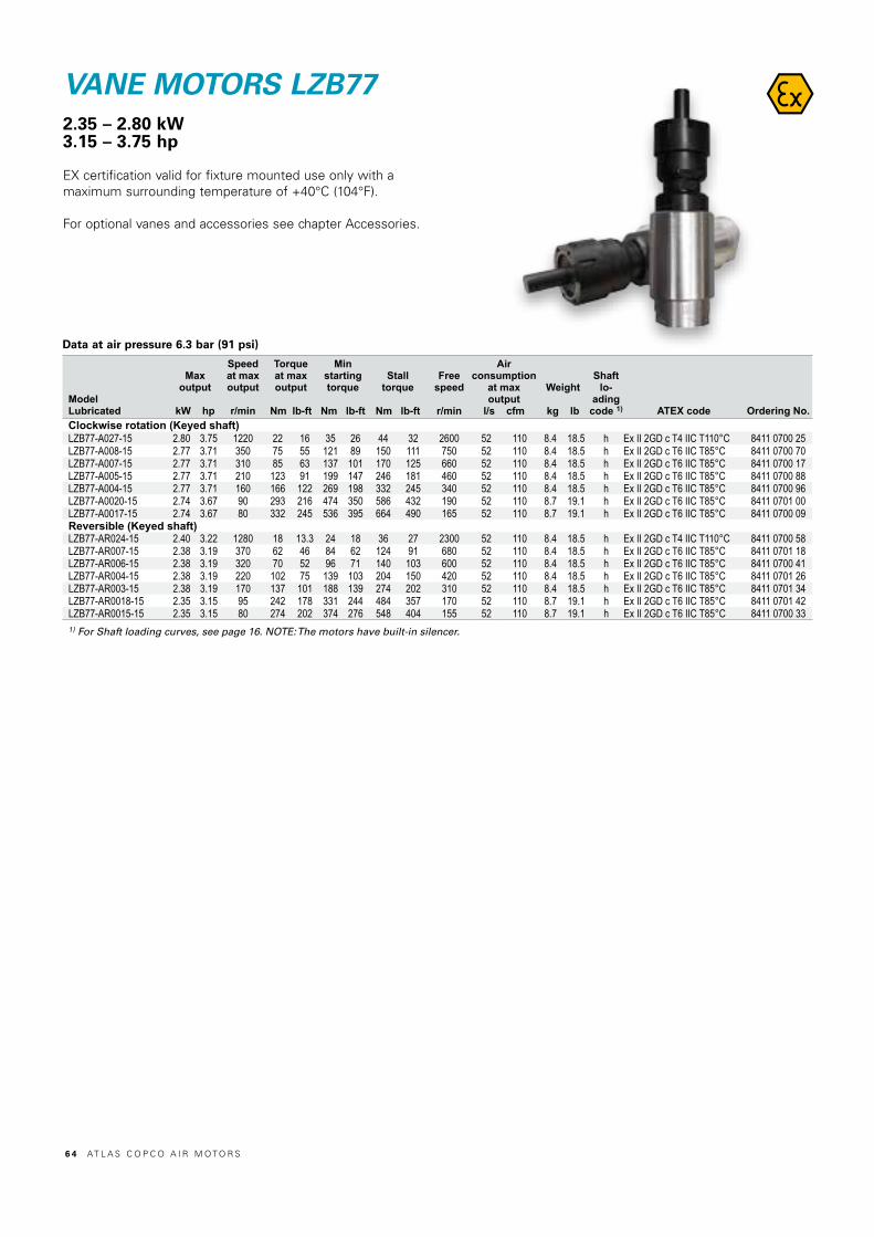
VANE MOTORS LZB772.35 – 2.80 kW3.15 – 3.75 hp
EX certification valid for fixture mounted use only with a maximum surrounding temperature of +40°C (104°F).
For optional vanes and accessories see chapter Accessories.
Data at air pressure 6.3 bar (91 psi)
ModelLubricated
Maxoutput
kW hp
Speedat maxoutput
r/min
Torqueat maxoutput
Nm lb-ft
Minstartingtorque
Nm lb-ft
Stalltorque
Nm lb-ft
Free speed
r/min
Airconsumption
at maxoutput
l/s cfm
Weight
kg lb
Shaft lo-
adingcode 1) ATEX code Ordering No.
Clockwise rotation (Keyed shaft) LZB77-A027-15 2.80 3.75 1220 22 16 35 26 44 32 2600 52 110 8.4 18.5 h Ex II 2GD c T4 IIC T110°C 8411 0700 25LZB77-A008-15 2.77 3.71 350 75 55 121 89 150 111 750 52 110 8.4 18.5 h Ex II 2GD c T6 IIC T85°C 8411 0700 70LZB77-A007-15 2.77 3.71 310 85 63 137 101 170 125 660 52 110 8.4 18.5 h Ex II 2GD c T6 IIC T85°C 8411 0700 17LZB77-A005-15 2.77 3.71 210 123 91 199 147 246 181 460 52 110 8.4 18.5 h Ex II 2GD c T6 IIC T85°C 8411 0700 88LZB77-A004-15 2.77 3.71 160 166 122 269 198 332 245 340 52 110 8.4 18.5 h Ex II 2GD c T6 IIC T85°C 8411 0700 96LZB77-A0020-15 2.74 3.67 90 293 216 474 350 586 432 190 52 110 8.7 19.1 h Ex II 2GD c T6 IIC T85°C 8411 0701 00LZB77-A0017-15 2.74 3.67 80 332 245 536 395 664 490 165 52 110 8.7 19.1 h Ex II 2GD c T6 IIC T85°C 8411 0700 09Reversible (Keyed shaft)LZB77-AR024-15 2.40 3.22 1280 18 13.3 24 18 36 27 2300 52 110 8.4 18.5 h Ex II 2GD c T4 IIC T110°C 8411 0700 58LZB77-AR007-15 2.38 3.19 370 62 46 84 62 124 91 680 52 110 8.4 18.5 h Ex II 2GD c T6 IIC T85°C 8411 0701 18LZB77-AR006-15 2.38 3.19 320 70 52 96 71 140 103 600 52 110 8.4 18.5 h Ex II 2GD c T6 IIC T85°C 8411 0700 41LZB77-AR004-15 2.38 3.19 220 102 75 139 103 204 150 420 52 110 8.4 18.5 h Ex II 2GD c T6 IIC T85°C 8411 0701 26LZB77-AR003-15 2.38 3.19 170 137 101 188 139 274 202 310 52 110 8.4 18.5 h Ex II 2GD c T6 IIC T85°C 8411 0701 34LZB77-AR0018-15 2.35 3.15 95 242 178 331 244 484 357 170 52 110 8.7 19.1 h Ex II 2GD c T6 IIC T85°C 8411 0701 42LZB77-AR0015-15 2.35 3.15 80 274 202 374 276 548 404 155 52 110 8.7 19.1 h Ex II 2GD c T6 IIC T85°C 8411 0700 331) For Shaft loading curves, see page 16. NOTE: The motors have built-in silencer.
6 4 AT L A S C O P C O A I R M O T O R S

Dimensions (mm) Conversion factor 1 mm = 0.04 inch
6.35 h7
28.1
5
Ø25.4 j6
12.4
3
19.35
BSP 1/2” OR NPTF 1/2”–14
19.35
THREAD DEPTH16mm
Ø88
.9 h
9
Ø62
.1 M6
4.2
2.7
25
44.5
57
48.2
369.3
312.3
130 45
Ø85
.5 h
10
Ø10
0
M8
(x6)
DE
PT
H 1
8mm
R38
.1
6 P9
A/F 80
23
BSP 1/2” OR NPTF 1/2”–14
A/F 70
A/F
70
LZ
B V
AN
E M
OT
OR
S
Reversible
Clockwise
23
Ø 77
127.5˚127.5˚
A/F 70
M5 Depth 10 (x3)
BSP 1/2" or NPTF 1/2"-14
10M32x1.5 Depth 15
Ø 95Ø 40
70
Center inlet Ordering No. 4430 2240 81
AT L A S C O P C O A I R M O T O R S 6 5
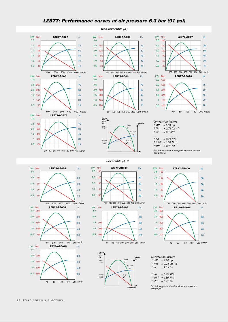
Nm LZB77-A005 l/s
r/min
kW
100 200 300 400 500
250
200
150
100
50
75
60
45
30
15
3.0
2.5
2.0
1.5
1
0.5
Nm LZB77-A0020 l/s
r/min
kW
40 80 160120 200
75
60
45
30
15
600
500
400
300
200
100
3.0
2.5
2.0
1.5
1
0.5
Nm LZB77-A027 l/s
r/min
kW
500
50
40
30
20
10
75
60
45
30
15
3.0
2.5
2.0
1.5
1.0
0.5
1000 1500 2000 2500
Nm LZB77-A008 l/s
r/min
kW
100
150
120
90
60
30
75
60
45
30
15
3.0
2.5
2.0
1.5
1.0
0.5
200 300 400 500 600 700 800
Nm LZB77-A007 l/s
r/min
kW
100
180
150
120
90
60
30
75
60
45
30
15
3.0
2.5
2.0
1.5
1.0
0.5
200 300 400 500 600 700
Nm LZB77-A0017 l/s
r/min
kW
20
750
600
450
300
150
75
60
45
30
15
3.0
2.5
2.0
1.5
1
0.5
40 60 80 100 120 140 160
Nm LZB77-A004 l/s
r/min
kW
400
300
200
100
75
60
45
30
15
3.0
2.5
2.0
1.5
1.0
0.5
50 100 150 200 250 300 350
LZB77: Performance curves at air pressure 6.3 bar (91 psi)
Non-reversible (A)
Conversion factors1 kW = 1.34 hp1 Nm = 0.74 Ibf - ft1 l/s = 2.1 cfm
1 hp = 0.75 kW1 Ibf-ft = 1.36 Nm1 cfm = 0.47 l/s
TorqueNmPowerkW
Maxoutput
Torqueat maxoutput
Torque
Power
Speed r/min
Air. cons.
Air cons.l/s
For information about performance curves, see page 7.
Nm LZB77-AR024 l/s
r/min
kW
40
30
20
10
80
60
40
20
2.5
2.0
1.5
1.0
0.5
500 1000 1500 2000 2500
Nm LZB77-AR007 l/s
r/min
kW150
120
90
60
30
80
60
40
20
2.5
2.0
1.5
1.0
0.5
100 200 300 400 500 600 700 800
Nm LZB77-AR006 l/s
r/min
kW150
120
90
60
30
80
60
40
20
2.5
2.0
1.5
1.0
0.5
100 200 300 400 500 600 700
Nm LZB77-AR004 l/s
r/min
kW250
200
150
100
50
80
60
40
20
2.5
2.0
1.5
1.0
0.5
100 200 300 400 500
Nm LZB77-AR003 l/s
r/min
kW
300
200
100
80
60
40
20
2.5
2.0
1.5
1.0
0.5
50 100 150 200 250 300 350
Nm LZB77-AR0018 l/s
r/min
kW500
400
300
200
100
80
60
40
20
2.5
2.0
1.5
1.0
0.5
40 80 120 160 200Nm LZB77-AR0015 l/s
r/min
kW
600
450
300
150
80
60
40
20
2.5
2.0
1.5
1.0
0.5
40 80 120 160 200
Reversible (AR)
Conversion factors1 kW = 1.34 hp1 Nm = 0.74 Ibf - ft1 l/s = 2.1 cfm
1 hp = 0.75 kW1 Ibf-ft = 1.36 Nm1 cfm = 0.47 l/s
TorqueNmPowerkW
Maxoutput
Torqueat maxoutput
Torque
Power
Speed r/min
Air. cons.
Air cons.l/s
For information about performance curves, see page 7.
6 6 AT L A S C O P C O A I R M O T O R S

Key chuck and quick chuck for LZB22/33-12
Collet chuck and collets for LZB22-12 to LZB66-12
Threaded shafts for re-building standard motors
ACCESSORIES FOR AIR MOTORS
Chuck type Mount
Body diameter
mmCapacity
mm Ordering No.Key chuck 3/8"-24 UNF 30 0 - 6.5 4021 0283 00Key chuck 3/8"-24 UNF 36 2.0 - 10.0 4021 0416 00Key chuck 3/8"-24 UNF 46 2.0 - 13.0 4021 0289 00Key chuck 1/2"-20 UNF 42.8 1.5 - 13 4021 0289 01Quick chuck 3/8"-24 UNF 34 0 - 6.5 4021 0401 00Quick chuck 3/8"-24 UNF 36 0 - 10.0 4021 0402 00Quick chuck 3/8"-24 UNF 36 2.0 - 13.0 4021 0403 00
Motor Thread dimension Ordering No.LZB42-A200 1/2"–20 UNF 4430 0868 80LZB42-A065 1/2"–20 UNF 4430 0868 80LZB42-A040 1/2"–20 UNF 4430 0868 81LZB42-A025 1/2"–20 UNF 4430 0868 82LZB42-A015 1/2"–20 UNF 4430 0869 80LZB42-A010 1/2"–20 UNF 4430 0869 80LZB42-A005 1/2"–20 UNF 4430 0869 80LZB42-A0030 3/4"–16 UNF 4430 0870 80LZB42-A0020 3/4"–16 UNF 4430 0870 80LZB42-A0012 3/4"–16 UNF 4430 0870 80LZB54 / LZB66-A180 1/2"–20 UNF 4430 0871 80LZB54 / LZB66-A050 1/2"–20 UNF 4430 0871 80LZB54 / LZB66-A030 1/2"–20 UNF 4430 0871 81LZB54 / LZB66 -A020 1/2"–20 UNF 4430 0871 82LZB54 / LZB66-A010 3/4"–16 UNF 4430 0870 80LZB54 / LZB66- A007 3/4"–16 UNF 4430 0870 80LZB54 / LZB66-A005 3/4"–16 UNF 4430 0870 80
TypeCapacity
Ordering No.mm inCollet holder cpl. 4110 0844 90Collet 3 4150 0081 00Collet 5 4150 0075 01Collet 6 4150 0075 00Collet 8 5/16" 4150 0074 00Collet 1/8" 4150 0082 00Collet 5/32" 4150 0648 00Collet 3/16" 4150 0649 00Collet 1/4" 4150 0076 00
AC
CE
SS
OR
IES
FO
R A
IR M
OT
OR
S
Safety remote control
Type Ordering No.Safety remote control 4430 2218 80
AT L A S C O P C O A I R M O T O R S 6 7

Stainless steel motor cell, LZB14Air Motor Motor cell
Model Ordering No. Ordering No.Clockwise rotation (Key shaft)LZB14-RL-A190-11 8411 0122 09 4430 2194 80LZB14-RL-A048-11 8411 0122 17 4430 2194 80LZB14-RL-A029-11 8411 0122 25 4430 2194 80LZB14-RL-A12-11 8411 0122 33 4430 2194 80LZB14-RL-A007-11 8411 0122 41 4430 2194 80Reversible (Key shaft)LZB14-RL-AR140-11 8411 0122 58 4430 2194 84LZB14-RL-AR034-11 8411 0122 66 4430 2194 84LZB14-RL-AR020-11 8411 0122 74 4430 2194 84LZB14-RL-AR008-11 8411 0122 82 4430 2194 84LZB14-RL-AR005-11 8411 0122 90 4430 2194 84
Stainless steel motor cell, LZB22Air Motor Motor cell
Model Ordering No. Ordering No.Clockwise rotation (Key shaft)LZB22-RL-A120-11 8411 0219 11 4430 2304 83LZB22-RL-A049-11 8411 0219 29 4430 2304 83LZB22-RL-A036-11 8411 0219 37 4430 2305 83LZB22-RL-A022-11 8411 0219 45 4430 2304 83LZB22-RL-A011-11 8411 0219 52 4430 2304 83LZB22-RL-A008-11 8411 0219 60 4430 2305 83LZB22-RL-A005-11 8411 0219 78 4430 2304 83Reversible (Key shaft)LZB22-RL-AR126-11 8411 0220 83 4430 2304 84LZB22-RL-AR028-11 8411 0220 75 4430 2304 84LZB22-RL-AR021-11 8411 0220 16 4430 2305 84LZB22-RL-AR013-11 8411 0220 67 4430 2304 84LZB22-RL-AR006-11 8411 0220 59 4430 2304 84LZB22-RL-AR005-11 8411 0220 08 4430 2305 84LZB22-RL-AR003-11 8411 0220 91 4430 2304 84
Stainless steel motor cell, LZB34Air Motor Motor cell
Model Ordering No. Ordering No.Clockwise rotation (Key shaft)LZB34-RL-A210-11 8411 0338 41 4430 2290 83LZB34-RL-A060-11 8411 0338 58 4430 2290 83LZB34-RL-A033-11 8411 0338 66 4430 2290 83LZB34-RL-A026-11 8411 0338 74 4430 2291 83LZB34-RL-A013-11 8411 0338 82 4430 2290 83LZB34-RL-A007-11 8411 0338 90 4430 2290 83LZB34-RL-A005-11 8411 0339 08 4430 2291 83Reversible (Key shaft)LZB34-RL-AR150-11 8411 0339 16 4430 2290 84LZB34-RL-AR043-11 8411 0339 24 4430 2290 84LZB34-RL-AR024-11 8411 0339 32 4430 2290 84LZB34-RL-AR019-11 8411 0339 40 4430 2291 84LZB34-RL-AR009-11 8411 0339 57 4430 2290 84LZB34-RL-AR005-11 8411 0339 65 4430 2290 84LZB34-RL-AR004-11 8411 0339 73 4430 2291 84
Stainless steel motor cell, LZB46Air Motor Motor cell
Model Ordering No. Ordering No.Clockwise rotation (Key shaft)LZB46-RL-A200-11 8411 0472 15 4430 1076 83LZB46-RL-A065-11 8411 0472 23 4430 1076 83LZB46-RL-A040-11 8411 0472 31 4430 1076 83LZB46-RL-A025-11 8411 0472 49 4430 1206 80LZB46-RL-A015-11 8411 0470 82 4430 1076 83LZB46-RL-A010-11 8411 0471 08 4430 1076 83LZB46-RL-A005-11 8411 0471 16 4430 1206 80LZB46-RL-A0030-11 8411 0471 24 4430 1076 83LZB46-RL-A0020-11 8411 0471 32 4430 1076 83LZB46-RL-A0012-11 8411 0471 40 4430 1206 80Reversible (Key shaft)LZB46-RL-AR170-11 8411 0472 56 4430 1076 84LZB46-RL-AR050-11 8411 0472 64 4430 1076 84LZB46-RL-AR030-11 8411 0472 72 4430 1076 84LZB46-RL-AR020-11 8411 0472 80 4430 1206 84LZB46-RL-AR010-11 8411 0471 57 4430 1076 84LZB46-RL-AR007-11 8411 0471 65 4430 1076 84LZB46-RL-AR004-11 8411 0471 73 4430 1206 84LZB46-RL-AR0025-11 8411 0471 81 4430 1076 84LZB46-RL-AR0015-11 8411 0471 99 4430 1076 84LZB46-RL-AR0010-11 8411 0472 07 4430 1206 84
ACCESSORIES FOR AIR MOTORS
For the complete range LZB34-RLB- Ordering No. 4430 2291 84
6 8 AT L A S C O P C O A I R M O T O R S
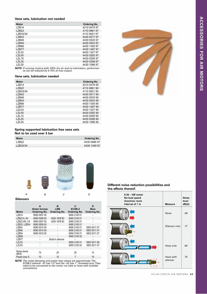
AC
CE
SS
OR
IES
FO
R A
IR M
OT
OR
S
Silencers
Vane sets, lubrication not needed
Spring supported lubrication free vane sets Not to be used over 3 bar
NOTE: The noise damping and power loss values are approximate. The ECSB-2 silencer –01 has 1/2”and the –02 has 1” threaded port. They need to be connected to the motor via tube or hose with suitable connections.
Motor Ordering No.LZB14 4210 0479 97LZB22 4110 0861 97LZB33/34 4110 0621 97LZB42 4430 0517 97LZB46 4430 0525 97LZB54 4430 0543 97LZB66 4430 1355 97LZB77 4430 1487 97LZL03 4430 1327 97LZL05 4430 0282 97LZL15 4430 0290 97LZL25 4430 0298 97LZL35 4430 1086 97
NOTE: If running motors with 100% dry air and no lubrication, performan-ce can be reduced by 5-15% at max output.
Motor Ordering No.LZB22 4430 0686 97LZB33/34 4430 1349 97
0.36 – kW motor No-load speed Noise Anechoic room level Interval of 1 m Measure dB(A)
None 94
Silencer only 77
Hose only 84
Hose with 75 silencer
Different noise reduction possibilities and the effects thereof:
Motor
ASinter bronzeOrdering No.
BLBB
Ordering No.
CECSB-2
Ordering No.
DBlue
Ordering No.LZB14 9090 0507 00 - 9090 2100 01 -LZB22 A, AV 9090 0508 00 4250 1878 83 9090 2100 01 -LZB22 AR, LR 9090 0507 00 4250 1878 83 9090 2100 01 -LZB33, LZB34 9090 0508 00 - 9090 2100 01 -LZB42 9090 0510 00 - 9090 2100 01 0803 5011 07LZB46 9090 0510 00 - 9090 2100 01 0803 5011 07LZB54 9090 0510 00 - 9090 2100 01 0803 5011 07LZB66 - - 9090 2100 02 -LZB77 - Build in silencer - -LZL03 - - 9090 2100 01 0803 5011 06LZL05 - - 9090 2100 02 0803 5011 07
Noise damp dB(A) 15 20 25 15Power loss % 10 10 7 10
A B C
Vane sets, lubrication needed
Motor Ordering No.LZB14 4210 0479 90LZB22 4110 0861 90LZB33/34 4110 0621 90LZB42 4430 0517 90LZB46 4430 0525 90LZB54 4430 0543 90LZB66 4430 1355 90LZB77 4430 1487 90LZL03 4430 1327 90LZL05 4430 0282 90LZL15 4430 0290 90LZL25 4430 0298 90LZL35 4430 1086 90
D
AT L A S C O P C O A I R M O T O R S 6 9

LZLVANE MOTORS
7 0 AT L A S C O P C O A I R M O T O R S
AT L A S C O P C O A I R M O T O R S 7 1

LZL VANE MOTORSIntroduction
1. Six vanes for high starting torque.2. Pins to force vanes out and provide starting reliability.3. Cast iron housing.4. Long life bearings.5. Restriction at inlet and outlet ports.
Figure 1
LZL vane motors are available in five sizes, offeringoutputs of 1.05 kW, 1.3 kW, 2.3 kW, 3.4 kW and 5.2 kW, respectively.
They are designed to give outstanding starting and low speed performance. This is achieved by using a six vane motor and by optimum vane/cylinder sealing – obtained through a com-bination of ‘vane air’ and interconnecting pins.
Featuring few components, these motors are ruggedlyconstructed and offer a long service life.
7 2 AT L A S C O P C O A I R M O T O R S
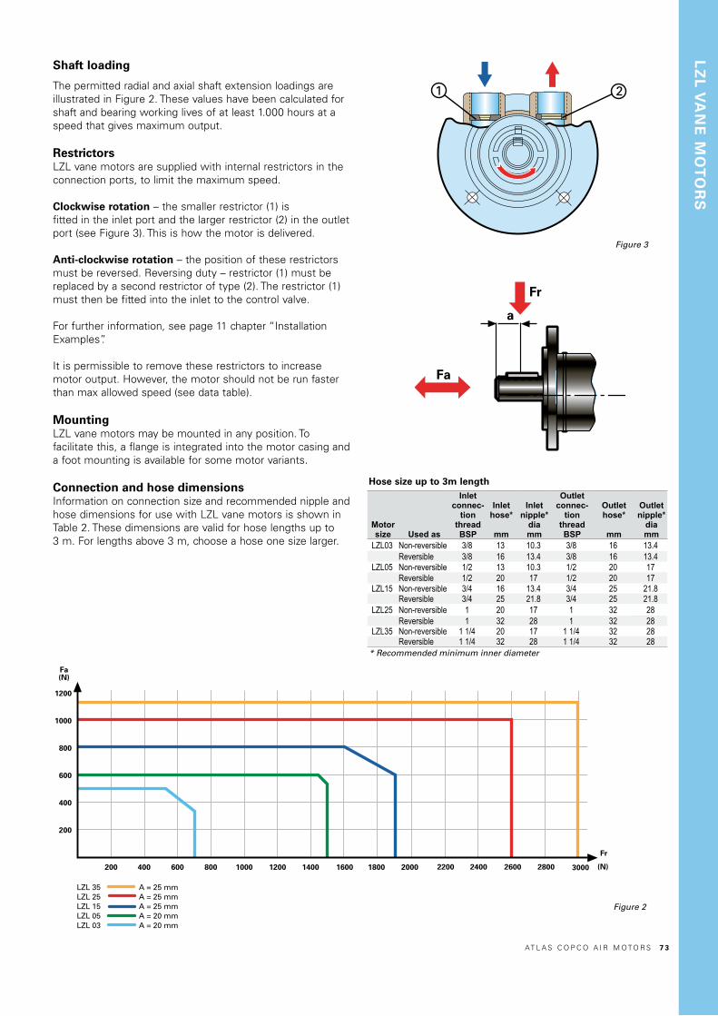
Shaft loading
The permitted radial and axial shaft extension loadings areillustrated in Figure 2. These values have been calculated forshaft and bearing working lives of at least 1.000 hours at aspeed that gives maximum output.
RestrictorsLZL vane motors are supplied with internal restrictors in theconnection ports, to limit the maximum speed.
Clockwise rotation – the smaller restrictor (1) isfitted in the inlet port and the larger restrictor (2) in the outletport (see Figure 3). This is how the motor is delivered.
Anti-clockwise rotation – the position of these restrictors must be reversed. Reversing duty – restrictor (1) must be replaced by a second restrictor of type (2). The restrictor (1) must then be fitted into the inlet to the control valve.
For further information, see page 11 chapter “Installation Examples”.
It is permissible to remove these restrictors to increasemotor output. However, the motor should not be run fasterthan max allowed speed (see data table).
MountingLZL vane motors may be mounted in any position. Tofacilitate this, a flange is integrated into the motor casing anda foot mounting is available for some motor variants.
Connection and hose dimensionsInformation on connection size and recommended nipple and hose dimensions for use with LZL vane motors is shown in Table 2. These dimensions are valid for hose lengths up to3 m. For lengths above 3 m, choose a hose one size larger.
Figure 2
Figure 3
Fr
1200
1000
800
600
400
200
200012001000800600400200
Fa(N)
1400 1600 1800
LZL 35LZL 25LZL 15LZL 05LZL 03
A = 25 mmA = 25 mmA = 25 mmA = 20 mmA = 20 mm
30002200 2400 2600 2800 (N)
Table 2
LZ
L V
AN
E M
OT
OR
S
Motor size Used as
Inletconnec-
tionthreadBSP
Inlethose*
mm
Inletnipple*
diamm
Outletconnec-
tionthreadBSP
Outlethose*
mm
Outletnipple*
diamm
LZL03 Non-reversible 3/8 13 10.3 3/8 16 13.4Reversible 3/8 16 13.4 3/8 16 13.4
LZL05 Non-reversible 1/2 13 10.3 1/2 20 17Reversible 1/2 20 17 1/2 20 17
LZL15 Non-reversible 3/4 16 13.4 3/4 25 21.8Reversible 3/4 25 21.8 3/4 25 21.8
LZL25 Non-reversible 1 20 17 1 32 28Reversible 1 32 28 1 32 28
LZL35 Non-reversible 1 1/4 20 17 1 1/4 32 28Reversible 1 1/4 32 28 1 1/4 32 28
* Recommended minimum inner diameter
Hose size up to 3m length
Fr
1200
1000
800
600
400
200
200012001000800600400200
Fa(N)
1400 1600 1800
LZL 35LZL 25LZL 15LZL 05LZL 03
A = 25 mmA = 25 mmA = 25 mmA = 20 mmA = 20 mm
30002200 2400 2600 2800 (N)
AT L A S C O P C O A I R M O T O R S 7 3
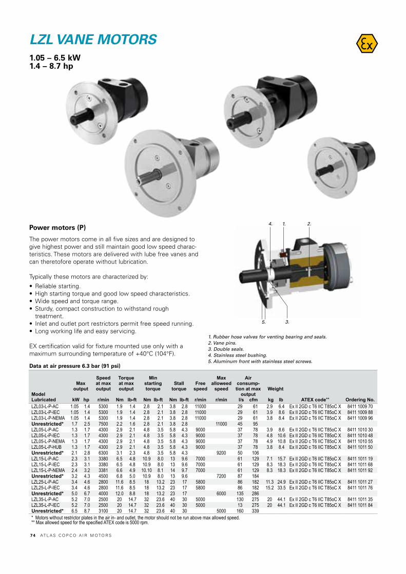
Power motors (P)
The power motors come in all five sizes and are designed to give highest power and still maintain good low speed charac-teristics. These motors are delivered with lube free vanes and can theretofore operate without lubrication.
Typically these motors are characterized by:
• Reliable starting.• High starting torque and good low speed characteristics.• Wide speed and torque range.• Sturdy, compact construction to withstand rough
treatment.• Inlet and outlet port restrictors permit free speed running.• Long working life and easy servicing.
EX certification valid for fixture mounted use only with amaximum surrounding temperature of +40°C (104°F).
1. Rubber hose valves for venting bearing and seals.2. Vane pins.3. Double seals.4. Stainless steel bushing.5. Aluminum front with stainless steel screws.
LZL VANE MOTORS1.05 – 6.5 kW1.4 – 8.7 hp
1.
5. 3.
4. 2.
ModelLubricated
Maxoutput
kW hp
Speedat maxoutput
r/min
Torqueat maxoutput
Nm lb-ft
Minstarting torque
Nm lb-ft
Stall torque
Nm lb-ft
Freespeed
r/min
Maxalloweed
speed
r/min
Airconsump-tion at max
outputl/s cfm
Weight
kg lb ATEX code** Ordering No.LZL03-L-P-AC 1.05 1.4 5300 1.9 1.4 2.8 2.1 3.8 2.8 11000 29 61 2.9 6.4 Ex II 2GD c T6 IIC T85oC X 8411 1009 70LZL03-L-P-IEC 1.05 1.4 5300 1.9 1.4 2.8 2.1 3.8 2.8 11000 29 61 3.9 8.6 Ex II 2GD c T6 IIC T85oC X 8411 1009 88LZL03-L-P-NEMA 1.05 1.4 5300 1.9 1.4 2.8 2.1 3.8 2.8 11000 29 61 3.8 8.4 Ex II 2GD c T6 IIC T85oC X 8411 1009 96Unrestricted* 1.7 2.5 7500 2.2 1.6 2.8 2.1 3.8 2.8 11000 45 95LZL05-L-P-AC 1.3 1.7 4300 2.9 2.1 4.8 3.5 5.8 4.3 9000 37 78 3.9 8.6 Ex II 2GD c T6 IIC T85oC X 8411 1010 30LZL05-L-P-IEC 1.3 1.7 4300 2.9 2.1 4.8 3.5 5.8 4.3 9000 37 78 4.8 10.6 Ex II 2GD c T6 IIC T85oC X 8411 1010 48LZL05-L-P-NEMA 1.3 1.7 4300 2.9 2.1 4.8 3.5 5.8 4.3 9000 37 78 4.9 10.8 Ex II 2GD c T6 IIC T85oC X 8411 1010 55LZL05-L-P-HUB 1.3 1.7 4300 2.9 2.1 4.8 3.5 5.8 4.3 9000 37 78 3.8 8.4 Ex II 2GD c T6 IIC T85oC X 8411 1011 50Unrestricted* 2.1 2.8 6300 3.1 2.3 4.8 3.5 5.8 4.3 9200 50 106LZL15-L-P-AC 2.3 3.1 3380 6.5 4.8 10.9 8.0 13 9.6 7000 61 129 7.1 15.7 Ex II 2GD c T6 IIC T85oC X 8411 1011 19LZL15-L-P-IEC 2.3 3.1 3380 6.5 4.8 10.9 8.0 13 9.6 7000 61 129 8.3 18.3 Ex II 2GD c T6 IIC T85oC X 8411 1011 68LZL15-L-P-NEMA 2.4 3.2 3381 6.6 4.9 10.10 8.1 14 9.7 7000 61 129 8.3 18.3 Ex II 2GD c T6 IIC T85oC X 8411 1011 92Unrestricted* 3.2 4.3 4500 6.8 5.0 10.9 8.0 13 9.6 7200 87 184LZL25-L-P-AC 3.4 4.6 2800 11.6 8.5 18 13.2 23 17 5800 86 182 11.3 24.9 Ex II 2GD c T6 IIC T85oC X 8411 1011 27LZL25-L-P-IEC 3.4 4.6 2800 11.6 8.5 18 13.2 23 17 5800 86 182 15.2 33.5 Ex II 2GD c T6 IIC T85oC X 8411 1011 76Unrestricted* 5.0 6.7 4000 12.0 8.8 18 13.2 23 17 6000 135 286LZL35-L-P-AC 5.2 7.0 2500 20 14.7 32 23.6 40 30 5000 130 275 20 44.1 Ex II 2GD c T6 IIC T85oC X 8411 1011 35LZL35-L-P-IEC 5.2 7.0 2500 20 14.7 32 23.6 40 30 5000 13 275 20 44.1 Ex II 2GD c T6 IIC T85oC X 8411 1011 84Unrestricted* 6.5 8.7 3100 20 14.7 32 23.6 40 30 5000 160 339* Motors without restrictor plates in the air in- and outlet, the motor should not be run above max allowed speed.** Max allowed speed for the specified ATEX code is 5000 rpm.
Data at air pressure 6.3 bar (91 psi)
7 4 AT L A S C O P C O A I R M O T O R S
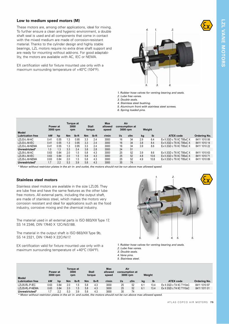
Low to medium speed motors (M)
These motors are, among other applications, ideal for mixing.To further ensure a clean and hygienic environment, a double shaft seal is used and all components that come in contact with the mixed medium are made of corrosion-resistant material. Thanks to the cylinder design and highly stable bearings, LZL motors require no extra drive shaft support and are ready for mounting without add-ons. For good adaptabi-lity, the motors are available with AC, IEC or NEMA.
EX certification valid for fixture mounted use only with amaximum surrounding temperature of +40°C (104°F).
Stainless steel motors
Stainless steel motors are available in the size LZL05. They are lube free and have the same features as the other lube free motors. All external parts, including the output shaft, are made of stainless steel, which makes the motors very corrosion resistant and ideal for applications such as the food industry, corrosive mixing and the chemical industry.
The material used in all external parts is ISO 683/Xlll Type 17, SS 14 2346, DIN 17440 X 12CrNiS188.
The material in the output shaft is ISO 683/Xlll Type 9b,SS 14 2321, DIN 17440 X 22CrNi17.
EX certification valid for fixture mounted use only with amaximum surrounding temperature of +40°C (104°F).
1. Rubber hose valves for venting bearing and seals.2. Lube free vanes.3. Double seals.4. Vane pins.5. Stainless steel.
1. Rubber hose valves for venting bearing and seals.2. Lube free vanes.3. Double seals.4. Stainless steel bushing.5. Aluminum front with stainless steel screws.6. Spring loaded pins.
1.
5. 3. 4. 5. 5.
2.
1.
5. 3.
4.
6.
2.
LZ
L V
AN
E M
OT
OR
S
ModelLubrication free
Power at3000 rpm
kW hp
Torque at 3000rpm
Nm lb-ft
Stalltorque
Nm lb-ft
Maxallowed speed
r/min
Airconsumption at
3000 rpm
l/s cfm
Weight
kg lb ATEX code Ordering No.LZL03-L-M-AC 0.41 0.55 1.3 0.95 3.3 2.4 3000 16 34 2.9 6.4 Ex II 2GD c T6 IIC T85oC X 8411 1010 06LZL03-L-M-IEC 0.41 0.55 1.3 0.95 3.3 2.4 3000 16 34 3.8 8.4 Ex II 2GD c T6 IIC T85oC X 8411 1010 14LZL03-L-M-NEMA 0.41 0.55 1.3 0.95 3.3 2.4 3000 16 34 3.9 8.6 Ex II 2GD c T6 IIC T85oC X 8411 1010 22Unrestricted* 1.0 1.3 3.3 2.4 3.8 2.8 3000 24 51LZL05-L-M-AC 0.63 0.84 2.0 1.5 5.8 4.3 3000 25 52 3.9 8.6 Ex II 2GD c T6 IIC T85oC X 8411 1010 63LZL05-L-M-IEC 0.63 0.84 2.0 1.5 5.8 4.3 3000 25 52 4.8 10.6 Ex II 2GD c T6 IIC T85oC X 8411 1010 71LZL05-L-M-NEMA 0.63 0.84 2.0 1.5 5.8 4.3 3000 25 52 4.9 10.8 Ex II 2GD c T6 IIC T85oC X 8411 1010 89Unrestricted* 1.7 2.2 5.3 3.9 5.8 4.3 3000 35 74* Motor without restrictor plates in the air in- and outlet, the motors should not be run above max allowed speed.
ModelLubrication free
Power at3000 rpm
kW hp
Torque at 3000rpm
Nm lb-ft
Stalltorque
Nm lb-ft
Maxallowed speed
r/min
Airconsumption at
3000 rpm
l/s cfm
Weight
kg lb ATEX code Ordering No.LZL05-RL-P-IEC 0.63 0.84 2.0 1.5 5.8 4.3 3000 25 52 6.1 13.4 Ex II 2GD c T4 IIC T110oC 8411 1010 97LZL05-RL-P-NEMA 0.63 0.84 2.0 1.5 5.8 4.3 3000 25 52 6.1 13.4 Ex II 2GD c T4 IIC T110oC 8411 1011 01Unrestricted* 1.7 2.2 5.3 3.9 5.8 4.3 3000 35 74* Motor without restrictor plates in the air in- and outlet, the motors should not be run above max allowed speed.
AT L A S C O P C O A I R M O T O R S 7 5

Air motorMeasurements (mm) Conversion factor 1 mm = 0.04 inch
LZL motors with IEC interface
Model A B C D E F G H I J K L M N O P R S T ULZL03-L-M/P-AC mm 124 Ø105 Ø70 j6 Ø16 j7 18 5 h9 40 30 2.0 2.5 8.5 M5x15 65 BSP ⅜” 36 Ø69 Ø85 Ø7 1 -LZL03-L-M/P-IEC mm 124 Ø160 Ø110 j6 Ø14 j7 16 5 h9 30 20 2.0 3.5 8.5 M5x15 65 BSP ⅜” 36 Ø69 Ø130 Ø10 - -LZL03-L-M/P-NEMA mm 124 Ø165.1 Ø114.3 Ø15.875 17.85 4.75 51.5 31.75 1.7 3.175 10 M5x15 65 BSP ⅜” 36 Ø69 Ø149.225 ⅜”-16 UNC 1 -LZL03-L-M/P-NEMA inch 4.88 Ø6.5 Ø4.5 Ø0.625 0.703 0.187 2.03 1.25 0.07 0.125 0.39 M5x15 2.56 BSP ⅜” 1.42 Ø2.72 Ø5.875 ⅜”-16 UNC 0.04 -LZL05-L-P-AC mm 152 Ø105 Ø70 j6 Ø18 j7 20.5 6 h9 40 30 3.0 2.5 8.5 M5x15 81 BSP ½” 44 Ø76 Ø85 Ø7 - -LZL05-L-M-AC mm 152 Ø105 Ø70 j6 Ø16 j7 18 5 h9 40 30 2.0 2.5 8.5 M5x15 81 BSP ½” 44 Ø76 Ø85 Ø7 0.5 -LZL05-L-M/P-IEC mm 152 Ø160 Ø110 j6 Ø14 j7 16 5 h9 30 20 2.0 3.5 8.5 M5x15 81 BSP ½” 44 Ø76 Ø130 Ø10 - -LZL05-L-M/P-NEMA mm 152 Ø165.1 Ø114.3 Ø15.875 17.85 4.75 51.5 31.75 1 3.175 10 M5x15 81 BSP ½” 44 Ø76 Ø149.225 ⅜”-16 UNC 0.5 -LZL05-L-M/P-NEMA inch 5.98 Ø6.5 Ø4.5 Ø0.625 0.703 0.187 2.03 1.25 0.04 0.125 0.39 M5x15 3.19 BSP ½” 1.73 Ø3 Ø5.875 ⅜”-16 UNC 0.02 -LZL05-L-P-HUB mm 152 Ø84 Ø44.45 j6 Ø12.7 14.51 3.175 H7 45 12.3 6.8 16 8.5 - 81 BSP ½” 44 Ø76 Ø63.6 ¼"-20 UNC 15.5 4.1LZL05-L-P-HUB inch 5.98 Ø3.31 Ø1.75 Ø0.5 0.57 0.125 1.77 0.5 0.3 0.63 0.335 - 3.19 BSP ½” 1.73 Ø3 Ø2.5 ¼"-20 UNC 0.61 0.161LZL05-RL-P-IEC mm 152 Ø160 Ø110 j6 Ø14 j7 16 5 h9 30 20 2.0 3.5 8.5 M5x15 81 BSP ½” 44 Ø76 Ø130 Ø10 - -LZL05-RL-P-NEMA mm 152 Ø165.1 Ø114.3 Ø15.875 17.85 4.75 51.5 31.75 1 3.175 10 M5x15 81 BSP ½” 44 Ø76 Ø149.225 ⅜”-16 UNC 0.5 -LZL05-RL-P-NEMA inch 5.98 Ø6.5 Ø4.5 Ø0.625 0.703 0.187 2.03 1.25 0.04 0.125 0.39 M5x15 3.19 BSP ½” 1.73 Ø3 Ø5.875 ⅜”-16 UNC 0.02 -LZL15-L-P-AC mm 181.5 Ø140 Ø95 j6 Ø22 j7 24.5 6 h9 52.5 40 5.0 3.0 12 M6x16 95 BSP 1" 54 Ø100 Ø115 Ø9 - -LZL15-L-P-IEC mm 181.5 Ø200 Ø130 j6 Ø19 j6 21.5 6 h9 40.5 30 5.0 3.5 12 M6x16 95 BSP 1" 54 Ø100 Ø165 Ø12 - -LZL15-L-P-NEMA mm 181.5 Ø165.1 Ø114.3 Ø15.875 17.85 4.75 51.5 31.75 1.5 3.175 12 M6x16 95 BSP 1" 54 Ø100 Ø149.225 ⅜”-16 UNC - -LZL15-L-P-NEMA inch 7.15 Ø6.5 Ø4.5 Ø0.625 0.703 0.187 2.03 1.25 0.06 0.125 0.472 M6x16 3.74 BSP 1" 2.13 Ø3.94 Ø5.875 ⅜”-16 UNC - -LZL25-L-P-AC mm 221 Ø160 Ø110 j6 Ø28 j7 31 8 h7 62.5 50 5.0 3 12 M10x22 118 BSP 1” 70 Ø120 Ø130 Ø10 - -LZL25-L-P-IEC mm 221 Ø200 Ø130 j6 Ø24 j6 27 8 h7 49.5 40 5.0 3.5 12 M10x22 118 BSP 1" 70 Ø120 Ø165 Ø12 - -LZL35-L-P-AC mm 248.5 Ø200 Ø130 j6 Ø28 j7 31 8 h7 60 50 5.0 3.5 14 M10x22 129 BSP 1¼" 70 Ø134 Ø165 Ø12 - -LZL35-L-P-IEC mm 248.5 Ø250 Ø180 j6 Ø28 j6 31 8 h7 60 50 5.0 4.0 14 M10x22 129 BSP 1¼" 70 Ø134 Ø215 Ø14.5 - -LZL35-P-IEC mm 248.5 Ø250 Ø180 j6 Ø28 j6 M10x22 60 4.0 - 5.0 50 14 129 134 BSP 1 1/4 70 Ø215 Ø14.5 31 8 h7
Model Flange mounting IEC frame Flange No.LZL03-L-M/P-IEC B5 71 FF 130LZL05-L-M/P-IEC B5 71 FF 130LZL05-RL-M/P-IEC B5 71 FF 130LZL15-L-P-IEC B5 80 FF 165LZL25-L-P-IEC B5 80 FF 165LZL35-L-P-IEC B5 100 FF 215
F
F
B
C
D
E
F
A
1 2 3 4 5 6 7 8 9 10Th
is d
ocum
ent i
s ou
r pro
perty
and
sha
ll no
t with
out o
ur p
erm
issi
on b
e al
tere
d,co
pied
, use
d fo
r man
ufac
turin
g or
com
mun
icat
ed to
any
oth
er p
erso
n or
com
pany
.
G
U
E F
I H
L C B
G
J K
A
P
45°
90°(4x)
S
D
R15
°(2x
)
M
N
O
T
Mod
el n
ame
Rev
.Ver
L
ZL03
-L-P
-AC
0.
2D
raw
ing
nam
eR
ev.V
er
LZL
_CAT
ALO
G
0.0
Note Pos. Modified from Date Intr.0 - - - -
Tolerances, if notindicated, according to:
- - - - -
AC-STD - - - - -Name Secrecy class VANE MOTOR LZL03-L-P-AC LZL03Material - 1102 K/-
CAD - Pro/E
Scale Format Family Compare Drawing owner1:1 A2 - 8411 1009 88
Drawn Blank Replaces D Öhlund - - TOOCons.class Rev Status Designation Sheet 1 (1)
Transferred from 1295 K/- 0 In WorkMass/Volume Date
- - 2016-05-23 8411 1009 70
LZL05-L-P-HUB
A
F-F
A
7 6 AT L A S C O P C O A I R M O T O R S
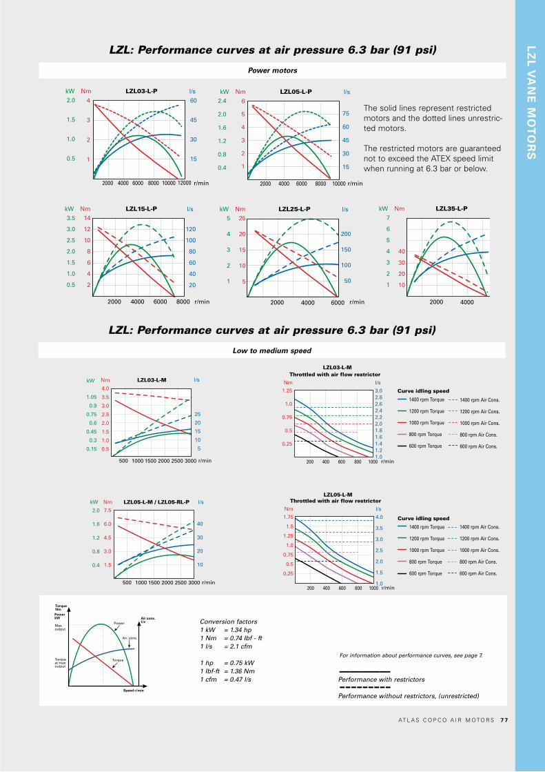
Conversion factors1 kW = 1.34 hp1 Nm = 0.74 Ibf - ft1 l/s = 2.1 cfm
1 hp = 0.75 kW1 Ibf-ft = 1.36 Nm1 cfm = 0.47 l/s
TorqueNmPowerkW
Maxoutput
Torqueat maxoutput
Torque
Power
Speed r/min
Air. cons.
Air cons.l/s
For information about performance curves, see page 7.
Performance with restrictors
Performance without restrictors, (unrestricted)
–––––---------
Nm LZL15-L-P l/s
r/min
kW
3.5
3.0
2.5
2.0
1.5
1.0
0.5
14
12
10
8
6
4
2
120
100
80
60
40
20
2000 4000 6000 8000
Nm LZL25-L-P l/s
r/min
kW
5
4
3
2
1
25
20
15
10
5
200
150
100
50
2000 4000 6000
Nm LZL35-L-P l/s
r/min
kW
7
6
5
4
3
2
1
40
30
20
10
240
200
160
120
80
40
2000 4000 6000
r/min
2.0
1.5
1.0
0.5
60
45
30
15
Nm LZL03-L-P l/skW
2000
4
3
2
1
4000 6000 8000 10000 12000
Nm LZL05-L-P l/skW
2000
6
5
4
3
2
1
4000 6000 8000 10000
2.4
2.0
1.6
1.2
0.8
0.4
75
60
45
30
15
r/min
Nm LZL05-L-M / LZL05-RL-P l/s
r/min1000 1500500
7.5
6.0
4.5
3.0
1.5
40
30
20
10
kW
2.0
1.6
1.2
0.8
0.4
2000 2500 3000
Nm LZL03-L-M l/s
4.0
3.5
3.0
2.5
2.0
1.5
1.0
0.5
25
20
15
10
5
kW
1.05
0.9
0.75
0.6
0.45
0.3
0.15
r/min1000 1500500 2000 2500 3000
Nm LZL05-L-M / LZL05-RL-P l/s
r/min1000 1500500
7.5
6.0
4.5
3.0
1.5
40
30
20
10
kW
2.0
1.6
1.2
0.8
0.4
2000 2500 3000
Nm LZL03-L-M l/s
4.0
3.5
3.0
2.5
2.0
1.5
1.0
0.5
25
20
15
10
5
kW
1.05
0.9
0.75
0.6
0.45
0.3
0.15
r/min1000 1500500 2000 2500 3000
r/min
3.02.82.62.42.22.01.81.61.41.21.0
Nm
LZL03-L-MThrottled with air flow restrictor
l/s
200
1.25
1.0
0.75
0.5
0.25
400 600 800 1000
r/min
4.0
3.5
3.0
2.5
2.0
1.5
1.0
Nm
LZL05-L-MThrottled with air flow restrictor
l/s
200
1.75
1.5
1.25
1.0
0.75
0.5
0.25
400 600 800 1000
1400 rpm Torque
1200 rpm Torque
1000 rpm Torque
800 rpm Torque
600 rpm Torque
Curve idling speed
1400 rpm Air Cons.
1200 rpm Air Cons.
1000 rpm Air Cons.
800 rpm Air Cons.
600 rpm Air Cons.
1400 rpm Torque
1200 rpm Torque
1000 rpm Torque
800 rpm Torque
600 rpm Torque
Curve idling speed
1400 rpm Air Cons.
1200 rpm Air Cons.
1000 rpm Air Cons.
800 rpm Air Cons.
600 rpm Air Cons.
r/min
3.02.82.62.42.22.01.81.61.41.21.0
Nm
LZL03-L-MThrottled with air flow restrictor
l/s
200
1.25
1.0
0.75
0.5
0.25
400 600 800 1000
r/min
4.0
3.5
3.0
2.5
2.0
1.5
1.0
Nm
LZL05-L-MThrottled with air flow restrictor
l/s
200
1.75
1.5
1.25
1.0
0.75
0.5
0.25
400 600 800 1000
1400 rpm Torque
1200 rpm Torque
1000 rpm Torque
800 rpm Torque
600 rpm Torque
Curve idling speed
1400 rpm Air Cons.
1200 rpm Air Cons.
1000 rpm Air Cons.
800 rpm Air Cons.
600 rpm Air Cons.
1400 rpm Torque
1200 rpm Torque
1000 rpm Torque
800 rpm Torque
600 rpm Torque
Curve idling speed
1400 rpm Air Cons.
1200 rpm Air Cons.
1000 rpm Air Cons.
800 rpm Air Cons.
600 rpm Air Cons.
LZL: Performance curves at air pressure 6.3 bar (91 psi)
Power motors
LZL: Performance curves at air pressure 6.3 bar (91 psi)
Low to medium speed
The solid lines represent restricted motors and the dotted lines unrestric-ted motors.
The restricted motors are guaranteed not to exceed the ATEX speed limit when running at 6.3 bar or below.
LZ
L V
AN
E M
OT
OR
S
AT L A S C O P C O A I R M O T O R S 7 7

1. Foot 2. Flange
Figure 5
LZL VANE MOTOR/GEAR UNIT COMBINATIONSCombined with helical gear units, LZLvane motors can be used over a very widetorque and speed range. Gears have a ratiorange between 6.3:1 to 164.5:1, corresponding to a speed range of 512 to 17 r/min and output torque up to 1836 Nm at max. output.
Helical gear units, type BF
Helical gear units are available in 2, 3, or 4-stage configura-tions. They deliver high efficiency levels and are available ina wide choice of ratios, Figure 4.
Calculating sprocket or gearwheel dimensions
If it is intended to fit a sprocket, gearwheel or pulley onto theoutput shaft, the radial load generated when running must bewithin the permitted level.
The following formula is used to calculate the minimum dia-meter of these components, to ensure the radial load doesnot exceed this limit.
Shaft loading
The maximum allowable radial load on the output shaft ofeach gear unit, at the halfway point on the shaft can beobtained from the data tables for each model.
The maximum permitted axial load is 20% of the table value for radial load if full permitted radial load is occurring. If there is no radial load the maximum permissible axial load is 50% of the table value for radial force.
Operating speed
To avoid damage to seals the gear units should not be runcontinuously above 4200 rpm.
Mounting
There are two options of mounting arrangement:Foot or Flange as illustrated in Figure 5.
Temperature
The gear units can operate within an ambient temperaturerange of –20°C (–4°F) and +40°C (104°F).
If it is required to use a gear unit outside these temperaturelimits please consult your local Atlas Copco representative.
Dmin = 2 x M x kt [m] F
where M = load torque in Nm F = permitted radial force halfway along the shaft extension kt = 1.0 for sprocket 1.3 for gear wheel 1.5 for pulley
Figure 4
7 8 AT L A S C O P C O A I R M O T O R S

Mounting position
Allowed mounting positions are shown below. Installing the motor underneath the gear unit is not allowed.
The alphanumeric numbers B3, B5, etc., are referred to in the product information enclosed at delivery.
B3 B5 B6 B51
B7 B53
V5 V1
B8 B52
NOTE: For some positions additional oil needs to be added to the gear box, see service instructions for details
V6 V3
AT L A S C O P C O A I R M O T O R S 7 9

AIR MOTORS LZL05with helical gear units1.2 – 2.0 kW1.7 – 2.6 hp
Model Ratio
Max output
kW hp
Speed atmax
output
r/min
Torquemax output
Nm lb-ft
Min startingtorque
Nm lb-ft
Freespeed
r/min
Maxallowedspeed
r/min
Air consump-tion at
max output
l/s cfm
Weight
kg lb
Max radialload at max
output
N Ordering No.LZL05-BF322-A-012 12.3 1.2 1.7 352 33 25 56 41 740 36 77 14 31 2360 8411 1808 40LZL05-BF322-B-012 12.3 1.2 1.7 352 33 25 56 41 740 36 77 14 31 2360 8411 1808 57Unrestricted* 12.3 2.0 2.6 512 36 27 56 41 740 54 114 14 31 2100LZL05-BF322-A-018 18.2 1.2 1.7 238 49 36 83 61 500 36 77 14 31 2770 8411 1808 65LZL05-BF322-B-018 18.2 1.2 1.7 238 49 36 83 61 500 36 77 14 31 2770 8411 1808 73Unrestricted* 18.2 2.0 2.6 346 54 40 83 61 500 54 114 14 31 2450LZL05-BF322-A-033 33.1 1.2 1.7 131 90 66 151 111 275 36 77 14 31 3370 8411 1808 81LZL05-BF322-B-033 33.1 1.2 1.7 131 90 66 151 111 275 36 77 14 31 3370 8411 1808 99Unrestricted* 33.1 2.0 2.6 190 97 72 151 111 275 54 114 14 31 3000LZL05-BF322-A-060 59.4 1.2 1.7 73 161 119 271 200 153 36 77 14 31 4800 8411 1809 07LZL05-BF322-B-060 59.4 1.2 1.7 73 161 119 271 200 153 36 77 14 31 4800 8411 1810 15Unrestricted* 59.4 2.0 2.6 106 174.9 129 271 200 153 54 114 14 31 4280LZL05-BF363-A-102 102.2 1.2 1.6 42 272 200 456 336 89 36 77 22 49 5650 8411 1810 23LZL05-BF363-B-102 102.2 1.2 1.6 42 272 200 456 336 89 36 77 22 49 5650 8411 1810 31Unrestricted* 102.2 1.9 2.6 62 295 217 456 336 89 54 114 22 49 5020LZL05-BF363-A-140 139.8 1.2 1.6 31 372 274 624 460 65 36 77 22 49 5690 8411 1810 49LZL05-BF363-B-140 139.8 1.2 1.6 31 372 274 624 460 65 36 77 22 49 5690 8411 1810 56Unrestricted* 139.8 1.9 2.6 45 403 297 624 460 65 54 114 22 49 5060*) Unrestricted, the motors should not be run without loadA = Foot mountB = Flange mount
Data at air pressure 6.3 bar (91 psi)
The LZL motor connects to the helical gear through an IEC interface
8 0 AT L A S C O P C O A I R M O T O R S
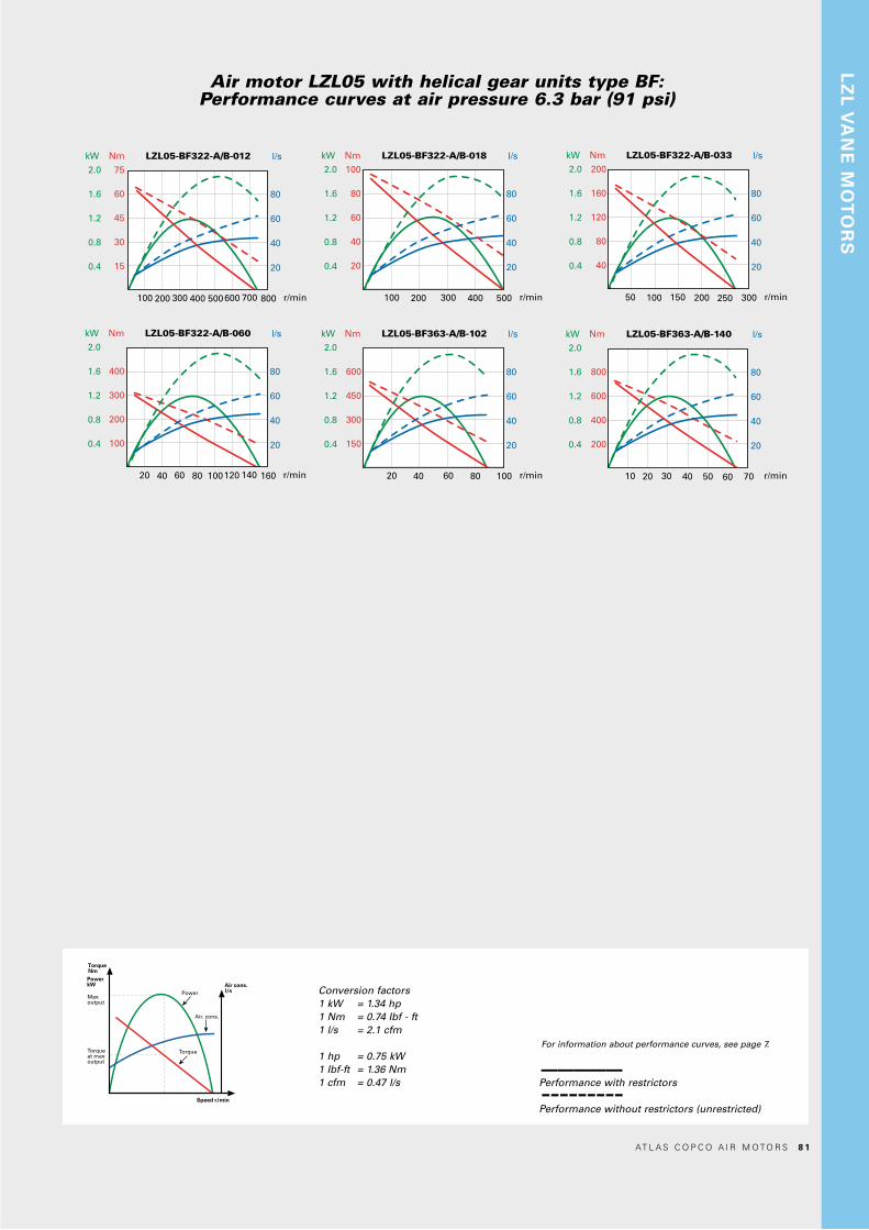
Nm LZL05-BF322-A/B-012 l/s
r/min
kW
2.0
1.6
1.2
0.8
0.4
75
60
45
30
15
80
60
40
20
100 200 600400 500 800300 700
Nm LZL05-BF322-A/B-018 l/s
r/min
kW
2.0
1.6
1.2
0.8
0.4
100
80
60
40
20
80
60
40
20
100 200 400 500300
Nm LZL05-BF322-A/B-033 l/s
r/min
kW
2.0
1.6
1.2
0.8
0.4
200
160
120
80
40
80
60
40
20
50 100 200 300150 250
Nm LZL05-BF322-A/B-060 l/s
r/min
kW
2.0
1.6
1.2
0.8
0.4
400
300
200
100
80
60
40
20
20 40 12080 100 16060 140
Nm LZL05-BF363-A/B-102 l/s
r/min
kW
2.0
1.6
1.2
0.8
0.4
600
450
300
150
80
60
40
20
20 40 80 10060
Nm LZL05-BF363-A/B-140 l/s
r/min
kW
2.0
1.6
1.2
0.8
0.4
800
600
400
200
80
60
40
20
10 20 40 7030 6050
Air motor LZL05 with helical gear units type BF:Performance curves at air pressure 6.3 bar (91 psi)
LZ
L V
AN
E M
OT
OR
S
Conversion factors1 kW = 1.34 hp1 Nm = 0.74 Ibf - ft1 l/s = 2.1 cfm
1 hp = 0.75 kW1 Ibf-ft = 1.36 Nm1 cfm = 0.47 l/s
TorqueNmPowerkW
Maxoutput
Torqueat maxoutput
Torque
Power
Speed r/min
Air. cons.
Air cons.l/s
For information about performance curves, see page 7.
Performance with restrictors
Performance without restrictors (unrestricted)
–––––---------
AT L A S C O P C O A I R M O T O R S 8 1

AIR MOTORS LZL15with helical gear units
2.1 – 3.0 kW2.9 – 4.1 hp
Model Ratio
Max output
kW hp
Speed atmax
output
r/min
Torquemax output
Nm lb-ft
Min startingtorque
Nm lb-ft
Freespeed
r/min
Maxallowedspeed
r/min
Air consump-tion at
max output
l/s cfm
Weight
kg lb
Max radialload at max
output
N Ordering No.LZL15-BF322-A-011 11.2 2.2 2.9 307 68 50 116 86 639 61 129 19 42 2530 8411 1810 61LZL15BF322-B-011 11.2 2.2 2.9 307 68 50 116 86 639 61 129 19 42 2530 8411 1810 79Unrestricted* 11.2 3.0 4.1 389 74 55 116 86 639 86 181 19 42 2310LZL15-BF322-A-018 18.2 2.2 2.9 189 111 82 188 139 393 61 129 19 42 2970 8411 1810 87LZL15-BF322-B-018 18.2 2.2 2.9 189 111 82 188 139 393 61 129 19 42 2970 8411 1810 95Unrestricted* 18.2 3.0 4.1 239 121 89.3 188 139 393 86 181 19 42 2710LZL15-BF322-A-033 33.1 2.2 2.9 104 202 149 343 253 216 61 129 19 42 3600 8411 1811 03LZL15-BF322-B-033 33.1 2.2 2.9 104 202 149 343 253 216 61 129 19 42 3600 8411 1811 11Unrestricted* 33.1 3.0 4.1 132 220 162 343 253 216 86 181 19 42 3300LZL15-BF322-A-060 59.4 2.2 2.9 58 362 267 615 454 120 61 129 19 42 5150 8411 1811 29LZL15-BF322-B-060 59.4 2.2 2.9 58 362 267 615 454 120 61 129 19 42 5150 8411 1811 37Unrestricted* 59.4 3.0 4.1 73 395 291 615 454 120 86 181 19 42 4710LZL15-BF363-A-102 102.2 2.1 2.9 34 609 449 1036 764 70 61 129 27 60 6040 8411 1811 45LZL15-BF363-B-102 102.2 2.1 2.9 34 609 449 1036 764 70 61 129 27 60 6040 8411 1811 52Unrestricted* 102.2 3.0 4.0 43 665 491 1036 764 70 86 181 27 60 5520LZL15-BF613-A-165 164.5 2.1 2.9 21 981 723 1668 1230 43 61 129 70 154 15000 8411 1811 60LZL15-BF613-B-165 164.5 2.1 2.9 21 981 723 1668 1230 43 61 129 70 154 15000 8411 1811 78Unrestricted* 164.5 3.0 4.0 26 1071 790 1668 1230 43 86 181 70 154 15000*) Unrestricted, the motors should not be run without loadA = Foot mountB = Flange mount
Data at air pressure 6.3 bar (91 psi)
The LZL motor connects to the helical gear through an IEC interface.
8 2 AT L A S C O P C O A I R M O T O R S

Air motor LZL15 with helical gear units type BF:Performance curves at air pressure 6.3 bar (91 psi)
Nm LZL15-BF322-A/B-011 l/s
r/min
kW
3.5
3.0
2.5
2.0
1.5
1.0
0.5
140
120
100
80
60
40
20
120
100
80
60
40
20
100 200 600400 500300 700
Nm LZL15-BF322-A/B-018 l/s
r/min
kW
3.5
3.0
2.5
2.0
1.5
1.0
0.5
240
200
160
120
80
40
120
100
80
60
40
20
50 100 300200250150 400350
Nm LZL15-BF322-A/B-033 l/s
r/min
kW
3.5
3.0
2.5
2.0
1.5
1.0
0.5
500
400
300
200
100
120
100
80
60
40
20
40 16012080 240200
Nm LZL15-BF322-A/B-060 l/s
r/min
kW
3.5
3.0
2.5
2.0
1.5
1.0
0.5
750
600
450
300
150
120
100
80
60
40
20
40 1008060 12020
Nm LZL15-BF363-A/B-102 l/s
r/min
kW
3.0
2.5
2.0
1.5
1.0
0.5
1200
1000
800
600
400
200
120
90
60
30
20 504030 7010 60
Nm LZL15-BF363-A/B-165 l/s
r/min
kW
3.0
2.5
2.0
1.5
1.0
0.5
2000
1600
1200
800
400
120
90
60
30
20 50403010
LZ
L V
AN
E M
OT
OR
S
Conversion factors1 kW = 1.34 hp1 Nm = 0.74 Ibf - ft1 l/s = 2.1 cfm
1 hp = 0.75 kW1 Ibf-ft = 1.36 Nm1 cfm = 0.47 l/s
TorqueNmPowerkW
Maxoutput
Torqueat maxoutput
Torque
Power
Speed r/min
Air. cons.
Air cons.l/s
For information about performance curves, see page 7.
Performance with restrictors
Performance without restrictors, (unrestricted)
–––––---------
AT L A S C O P C O A I R M O T O R S 8 3

AIR MOTORS LZL25with helical gear units3.3 – 4.8 kW4.4 – 6.4 hp
The LZL motor connects to the helical gear through an IEC interface.
Model Ratio
Max output
kW hp
Speed atmax
output
r/min
Torquemax output
Nm lb-ft
Min startingtorque
Nm lb-ft
Freespeed
r/min
Maxallowedspeed
r/min
Air consump-tion at
max output
l/s cfm
Weight
kg lb
Max radialload at max
output
N Ordering No.LZL25-BF322-A-011 11.2 3.3 4.4 254 123 91 192 141 531 86 183 26 57 2700 8411 1811 86LZL25-BF322-B-011 11.2 3.3 4.4 254 123 91 192 141 531 86 183 26 57 2700 8411 1811 94Unrestricted* 11.2 4.8 6.4 370 128 94 192 141 531 140 297 26 57 2430LZL25-BF322-A-018 18.2 3.3 4.4 156 201 148 311 230 327 86 183 26 57 3170 8411 1812 02LZL25-BF322-B-018 18.2 3.3 4.4 156 201 148 311 230 327 86 183 26 57 3170 8411 1812 10Unrestricted* 18.2 4.8 6.4 227 207 153 311 230 327 140 297 26 57 2860LZL25-BF363-A-035 34.6 3.2 4.3 82 373 275 579 427 172 86 183 34 75 4100 8411 1812 28LZL25-BF363-B-035 34.6 3.2 4.3 82 373 275 579 427 172 86 183 34 75 4100 8411 1812 36Unrestricted* 34.6 4.7 6.2 120 386 285 579 427 172 140 297 34 75 3700L25-BF613-A-059 58.6 3.2 4.3 48 632 466 981 724 101 86 183 77 170 13000 8411 1812 44LZL25-BF613-B-059 58.6 3.2 4.3 48 632 466 981 724 101 86 183 77 170 13000 8411 1812 51Unrestricted* 58.6 4.7 6.2 71 654 482 981 724 101 140 297 77 170 11700LZL25-BF613-A-114 113.6 3.2 4.3 25 1226 904 1902 1403 52 86 183 77 170 16000 8411 1812 69LZL25-BF613-B-114 113.6 3.2 4.3 25 1226 904 1902 1403 52 86 183 77 170 16000 8411 1812 77Unrestricted* 113.6 4.7 6.2 36 1268 935 1902 1403 52 140 297 77 170 16000LZL25-BF613-A-165 164.5 3.2 4.3 17 1775 1309 2754 2031 36 86 183 77 170 16000 8411 1812 85LZL25-BF613-B-165 164.5 3.2 4.3 17 1775 1309 2754 2031 36 86 183 77 170 16000 8411 1812 94Unrestricted* 164.5 4.7 6.2 25 1836 1354 2754 2031 36 140 297 77 170 16000*) Unrestricted, the motors should not be run without loadA = Foot mountB = Flange mount
Data at air pressure 6.3 bar (91 psi)
8 4 AT L A S C O P C O A I R M O T O R S

Air motor LZL25 with helical gear units type BF:Performance curves at air pressure 6.3 bar (91 psi)
Nm LZL25-BF322-A/B-011 l/s
r/min
kW
5
4
3
2
1
250
200
150
100
50
200
150
100
50
100 500300 400200 600
Nm LZL25-BF322-A/B-018 l/s
r/min
kW
5
4
3
2
1
400
300
200
100
200
150
100
50
50 300150 200100 350250
Nm LZL25-BF363-A/B-035 l/s
r/min
kW
5
4
3
2
1
750
600
450
300
150
200
150
100
50
40 80 120 200160
Nm LZL25-BF613-A/B-059 l/s
r/min
kW
5
4
3
2
1
1500
1200
900
600
300
200
150
100
50
20 10060 8040 120
Nm LZL25-BF613-A/B-114 l/s
r/min
kW
5
4
3
2
1
2500
2000
1500
1000
500
200
150
100
50
10 5030 4020 60
Nm LZL25-BF613-A/B-165 l/s
r/min
kW
5
4
3
2
1
4000
3000
2000
1000
200
150
100
50
5 3515 2010 4025 30
LZ
L V
AN
E M
OT
OR
S
Conversion factors1 kW = 1.34 hp1 Nm = 0.74 Ibf - ft1 l/s = 2.1 cfm
1 hp = 0.75 kW1 Ibf-ft = 1.36 Nm1 cfm = 0.47 l/s
TorqueNmPowerkW
Maxoutput
Torqueat maxoutput
Torque
Power
Speed r/min
Air. cons.
Air cons.l/s
For information about performance curves, see page 7.
Performance with restrictors
Performance without restrictors, (unrestricted)
–––––---------
AT L A S C O P C O A I R M O T O R S 8 5

AIR MOTORS LZL35with helical gear units5.1 – 6.3 kW6.8 – 8.4 hp
Model Ratio
Max output
kW hp
Speed atmax
output
r/min
Torquemax output
Nm lb-ft
Min startingtorque
Nm lb-ft
Freespeed
r/min
Maxallowedspeed
r/min
Air cons. atmax output
l/s cfm
Weight
kg lb
Max radialload at max
output
N Ordering No.LZL35-BF322-A-006 6.3 5.0 6.7 394 121 90 192 141 838 129 273 34 75 2360 8411 1813 01LZL35-BF322-B-006 6.3 5.0 6.7 394 121 90 192 141 838 129 273 34 75 2360 8411 1813 19Unrestricted* 6.3 6.2 8.3 464 128 94 192 141 838 159 337 34 75 2230LZL35-BF322-A-011 11.2 5.0 6.7 221 216 159 340 251 471 129 273 34 75 2810 8411 1813 27LZL35-BF322-B-011 11.2 5.0 6.7 221 216 159 340 251 471 129 273 34 75 2810 8411 1813 35Unrestricted* 11.2 6.2 8.3 261 227 167 340 251 471 159 337 34 75 2650LZL35-BF613-A-029 29.4 4.9 6.6 84 555 409 875 645 180 129 273 85 187 10600 8411 1813 43LZL35-BF613-B-029 29.4 4.9 6.6 84 555 409 875 645 180 129 273 85 187 10600 8411 1813 50Unrestricted* 29.4 6.1 8.1 99 583 430 875 645 180 159 337 85 187 10000LZL35-BF613-A-048 47.6 4.9 6.6 52 899 663 1417 1045 111 129 273 85 187 12100 8411 1813 68LZL35-BF613-B-048 47.6 4.9 6.6 52 899 663 1417 1045 111 129 273 85 187 12100 8411 1813 78Unrestricted* 47.6 6.1 8.1 61 944 696 1417 1045 111 159 337 85 187 11400*) Unrestricted, the motors should not be run without loadA = Foot mountB = Flange mount
Data at air pressure 6.3 bar (91 psi)
The LZL motor connects to the helical gear through an IEC interface.
8 6 AT L A S C O P C O A I R M O T O R S

Air motor LZL35 with helical gear units type BF:Performance curves at air pressure 6.3 bar (91 psi)
Nm LZL35-BF322-A/B-006 l/s
r/min
kW
7
6
5
4
3
2
1
240
200
160
120
80
40
240
200
160
120
80
40
200 800600400 1000
Nm LZL35-BF322-A/B-011 l/s
r/min
kW
7
6
5
4
3
2
1
500
400
300
200
100
240
200
160
120
80
40
100 400300200 500
Nm LZL35-BF613-A/B-029 l/s
r/min
kW
7
6
5
4
3
2
1
1050
900
750
600
450
300
150
240
200
160
120
80
40
40 16012080 200
Nm LZL35-BF613-A/B-048 l/s
r/min
kW
7
6
5
4
3
2
1
1800
1500
1200
900
600
300
240
200
160
120
80
40
20 806040 120100
LZ
L V
AN
E M
OT
OR
S
Conversion factors1 kW = 1.34 hp1 Nm = 0.74 Ibf - ft1 l/s = 2.1 cfm
1 hp = 0.75 kW1 Ibf-ft = 1.36 Nm1 cfm = 0.47 l/s
TorqueNmPowerkW
Maxoutput
Torqueat maxoutput
Torque
Power
Speed r/min
Air. cons.
Air cons.l/s
For information about performance curves, see page 7.
Performance with restrictors
Performance without restrictors, (unrestricted)
–––––---------
AT L A S C O P C O A I R M O T O R S 8 7

DIMENSIONS LZL WITH HELICAL GEAR UNITSFoot modelsConversion factor 1 mm = 0.04 inch
Conversion factor 1 mm = 0.04 inch
DIMENSIONS LZL WITH HELICAL GEAR UNITS Flange models
LZL type BF FOOT
Model A B C D E F G H I J K L M N O P Q R S T U V XLZL05-BF322-A-xxx 33 8 h9 30 h6 181 110 5.0 60 50 78 130 70 156 459.5 M10x22 BSP 1/2 71 Ø76 42 Ø160 Ø11 160 190 20LZL05-BF363-A-xxx 38 10 h9 35 h6 206 115 5.0 70 60 93.5 130 N/A 168 478 M10x22 BSP 1/2 71 Ø76 42 Ø160 Ø14 170 205 16LZL15-BF322-A-xxx 33 8 h9 30 h6 181 110 5.0 60 50 78 130 70 156 509 M10x22 BSP 3/4 86.5 Ø100 55 Ø200 Ø11 160 190 20LZL15-BF363-A-xxx 38 10 h9 35 h6 206 115 5.0 70 60 93.5 130 N/A 168 527.5 M10x22 BSP 3/4 86.5 Ø100 55 Ø200 Ø14 170 205 16LZL15-BF613-A-xxx 53.5 14 h9 50 h6 316 195 5.0 100 90 125 180 N/A 232 617 M16x36 BSP 3/4 86.5 Ø100 55 Ø200 Ø18 250 300 25LZL25-BF322-A-xxx 33 8 h9 30 h6 181 110 5.0 60 50 78 130 70 156 547.5 M10x22 BSP 1 103 Ø120 62 Ø200 Ø11 160 190 20LZL25-BF363-A-xxx 38 10 h9 35 h6 206 115 5.0 70 60 93.5 130 N/A 168 566 M10x22 BSP 1 103 Ø120 62 Ø200 Ø14 170 205 16LZL25-BF613-A-xxx 53.5 14 h9 50 h6 316 195 5.0 100 90 125 180 N/A 232 655.5 M16x36 BSP 1 103 Ø120 62 Ø200 Ø18 250 300 25LZL35-BF322-A-xxx 33 8 h9 30 h6 181 110 5.0 60 50 78 130 70 156 585.5 M10x22 BSP 1 1/4 119.5 Ø134 68 Ø250 Ø14 160 190 20LZL35-BF613-A-xxx 53.5 14 h9 50 h6 316 195 5.0 100 90 125 180 N/A 232 692.5 M16x36 BSP 1 1/4 119.5 Ø134 68 Ø250 Ø18 250 300 25
LZL type BF FLANGE
Model A B C D E F G H I J K L M N O P Q R S TLZL05-BF322-B-xxx 33 8 h9 30 h6 Ø250 Ø180 f7 5.0 60 50 4.0 13 459.5 108 Ø160 M10x22 BSP 1/2 71 Ø76 42 Ø215 Ø14LZL05-BF363-B-xxx 38 10 h9 35 h6 Ø250 Ø180 f7 5.0 70 60 4.0 14 478 111 Ø160 M10x22 BSP 1/2 71 Ø76 42 Ø215 Ø14LZL15-BF322-B-xxx 33 8 h9 30 h6 Ø250 Ø180 f7 5.0 60 50 4.0 13 509 108 Ø200 M10x22 BSP 3/4 86.5 Ø100 55 Ø215 Ø14LZL15-BF363-B-xxx 38 10 h9 35 h6 Ø250 Ø180 f7 5.0 70 60 4.0 14 527.5 111 Ø200 M10x22 BSP 3/4 86.5 Ø100 55 Ø215 Ø14LZL15-BF613-B-xxx 53.5 14 h9 50 h6 Ø300 Ø230 f7 5.0 100 90 4.0 16 617 178.5 Ø200 M16x36 BSP 3/4 86.5 Ø100 55 Ø265 Ø14LZL25-BF322-B-xxx 33 8 h9 30 h6 Ø250 Ø180 f7 5.0 60 50 4.0 13 547.5 108 Ø200 M10x22 BSP 1 103 Ø120 62 Ø215 Ø14LZL25-BF363-B-xxx 38 10 h9 35 h6 Ø250 Ø180 f7 5.0 70 60 4.0 14 566 111 Ø200 M10x22 BSP 1 103 Ø120 62 Ø215 Ø14LZL25-BF613-B-xxx 53.5 14 h9 50 h6 Ø300 Ø230 f7 5.0 100 90 4.0 16 655.5 178.5 Ø200 M16x36 BSP 1 103 Ø120 62 Ø265 Ø14LZL35-BF322-B-xxx 33 8 h9 30 h6 Ø250 Ø180 f7 5.0 60 50 4.0 13 585.5 108 Ø250 M10x22 BSP 1 1/4 119.5 Ø134 68 Ø215 Ø14LZL35-BF613-B-xxx 53.5 14 h9 50 h6 Ø300 Ø230 f7 5.0 100 90 4.0 16 692.5 178.5 Ø250 M16x36 BSP 1 1/4 119.5 Ø134 68 Ø265 Ø14
B
ØC
A
N D
E
F
G
H
M
O
P
R
ØQ
K
J
L
I
U
ØT
ØS
V
XB
ØC
A
N
ØD
ØE
F
H
G
J
I
L
O
P
K
R
ØQ
ØM
ØS
ØT
B
ØC
A
N D
E
F
G
H
M
O
P
R
ØQ
K
J
L
I
U
ØT
ØS
V
X
B
ØC
A
N
ØD
ØE
F
H
G
J
I
L
O
P
K
R
ØQ
ØM
ØS
ØT
8 8 AT L A S C O P C O A I R M O T O R S
AT
EX
EXPLOSION PREVENTION GUIDELINES
In addition to the product instructions for air motors, the following guidelines apply to explosion protected air motors.
Temperatures
• The maximum surrounding temperature for which the certification is valid is 40°C (104°F).
• 40°C (104°F) is also the maximum allowed temperature of the compressed air when it enters the motor.
• If the motor is installed in a equipment, the entire equip-ment has to correspond to the guidelines 2014/35/EU.
• Make sure that the compressed air fulfill our quality demands (quality classes 2.4.3. and 3.4.4 respectively 3.5.4 acc. to ISO/DIS 8573-1).
• Do not exceed maximum pressure of 6.3 bar, or as stated on the motor nameplate. Exceeding the operating pressure can increase the surface temperature due to higher rota-ting speed and the motor can become an ignition source.
AT L A S C O P C O A I R M O T O R S 8 9

ATEX CODE DEFINITION
ATEX certificate:
For information about the ATEX certificate, refer to the ATEX Technical File, 9836 4610 00.If the product is part of an assembly where the components have different ATEX codes, the component withthe lowest level of safety defines the ATEX code of the whole assembly.
Description Value DefinitionEquipment group I Mining applications
II Surface industryEquipment category Group I M1 May continue to operate when a potentially explosive atmosphere is present
M2 Shall not operate when a potentially explosive atmosphere is present.Equipment category Group II 1 Very high level of protection
• zone 0 (gas)• zone 1 (gas)• zone 2 (gas)• zone 20 (dust)• zone 21 (dust)• zone 22 (dust)
2 High level of protection• zone 1 (gas)• zone 2 (gas)• zone 21 (dust)• zone 22 (dust)
3 Normal level of protection• zone 2 (gas)• zone 22 (dust)
Atmosphere G Atmosphere containing Gas, Vapors or MistD Atmosphere containing Dust
Safety design c Constructional safetyType of protection Ex nL Explosion protection. Type: “Energy limited apparatus and circuits”Gas group IIA Propane/Acetone/Ammonia
IIB EthyleneIIC Hydrogen/Acetylene
Max surface temperature in Gas T1 = 450°C (848°F)T2 = 300°C (572°F)T3 = 200°C (392°F)T4 = 135°C (275°F)T5 = 100°C (212°F)T6 = 85°C (185°F)
Max surface temperature in Dust Example temperatures: T85°C (185°F)T110°C (230°F)T120°C (248°F)T125°C (257°F)T240°C (464°F)
Ambient temperature range Ta Example:20°C Ta +40°C
9 0 AT L A S C O P C O A I R M O T O R S

SPECIAL MOTORSAtlas Copco is a premier supplier of air motors, manufactured to individual customer specifications.
Particularly for ”OEM” requirements, a customized air motor can be the most efficient solution when integrating an air motor into a machine or tool. Typical examples of special motors are those having unique casing or mounting arrange-ments, motors utilizing non-standard materials or surface coatings and types designed to achieve a specific output.
Whatever the requirement, Atlas Copco welcomes the opportunity to work with its customers in finding the best solution for their needs.
AT L A S C O P C O A I R M O T O R S 9 1

NOTES
9 2 AT L A S C O P C O A I R M O T O R S

AT L A S C O P C O A I R M O T O R S 9 3

NOTES
9 4 AT L A S C O P C O A I R M O T O R S


www.atlascopco.com
9833
899
8 01
20
17:2
www.atlascopco.com