staff research study - usitc · staff research study, ... stu dies also linked the development of...
TRANSCRIPT
Staff ResearchStudy,,,,,,,,,,,,,,,
22,,,,,,,,,,,,,,,
Office of IndustriesU.S. International Trade Commission
Commercialization of New ManufacturingProcesses for Materials
April 1998
Publication 3100
The views expressed in this staff study are those of the Office of Industries, U.S. InternationalTrade Commission. They are not necessarily the views of the U.S. International Trade Commissionor any of the Commissioners.

U.S. International Trade CommissionOffice of Industries
,,,,,,,,,,,,,,,,,,
Vern SimpsonDirector of Industries
,,,,,,,,,,,,,,,,,,
David Lundy, Project Leader
Contributing Authors
Vincent DeSapioElizabeth HowlettRobert Kaproth
Susan LusiCheryl Qassis
Karl TsujiCharles Yost
With assistance from:
Diane BennettZema Tucker
Under the direction of:
Karen Laney-Cummings, ChiefIndustrial Minerals and Nonferrous Metals Branch
Larry Brookhart, ChiefMinerals, Metals, Machinery, and Miscellaneous Manufactures Division
Address inquires to:Director of Industries
U.S. International Trade Commission500 E St., SW
Washington, DC 20436Fax: 202-205-3161

i
Visit the USITC’s Internet Server to find more informationabout the agency and to download this and other USITC reports.
http://www.usitc.gov or ftp://usitc.gov
,,,,,,,,,,,,,,,,
PREFACE
The U.S. International Trade Commission (USITC) Office of Industries has researched thecommercialization of new manufacturing processes for materials since 1993. The NationalCritical Technologies Panel, appointed by the President’s Office of Science andTechnology, and the Council on Competitiveness, an association of private-sector chiefexecutives representing business, higher education, and labor, identified new processingtechnologies as crucial to improving competitiveness of U.S. industries. The results of theUSITC research on developments related to these technologies have been publishedperiodically as individual articles in the Industry, Trade, and Technology Review (ITTR),a quarterly staff publication of the Office of Industries. These articles are reprinted in thisstaff research study, and, in most cases, include a section describing recent developments.An overview of the research objectives and executive summary of the key findings derivedfrom the research are provided at the outset. In addition, several other published ITTRarticles covering materials technology are included to provide an understanding of the scopeof advanced technologies that have potential future implications for U.S. industrialcompetitiveness.
The information and analysis in this staff study are for the purpose of this report only.Nothing in this report should be construed to indicate how the Commission would find inan investigation conducted under other statutory authority. For additional information,please direct inquiries to David Lundy, Project Leader at (202) 205-3439 or electronic mailat [email protected].

iii
,,,,,,,,,,,,,,,,
CONTENTS
Preface . . . . . . . . . . . . . . . . . . . . . . . . . . . . . . . . . . . . . . . . . . . . . . . . . . . . . . i
Overview and executive summary . . . . . . . . . . . . . . . . . . . . . . . . . . . . . . . . . . . 1
Part I: New manufacturing processes for materials . . . . . . . . . . . . . . . . . . . . 5
Factors affecting the commercialization of new manufacturingprocesses for materials (Karl Tsuji, 202-205-3434) . . . . . . . . . . . . 7
Incentives for developing and adopting NMPM . . . . . . . . . . . . . . . . . . . . 9Confronting the barriers to commercializing NMPM . . . . . . . . . . . . . . . . 11Outlook: Further actions for effective commercialization of NMPM . . . 18
New manufacturing processes for materials: Government policies and programs towards commercialization (Dana Abrahamson and Cheryl Badra Qassis, 202-205-3436) . . . . . 23
Shifts in government focus . . . . . . . . . . . . . . . . . . . . . . . . . . . . . . . . . . . . 24Framework for government involvement . . . . . . . . . . . . . . . . . . . . . . . . . 26Outlook for increased government involvement . . . . . . . . . . . . . . . . . . . . 29Recent developments . . . . . . . . . . . . . . . . . . . . . . . . . . . . . . . . . . . . . . . . 33
Alternate materials in the U.S. automobile industry promotedevelopment of joining and bonding technology(Susan Lusi, 202-205-2334) . . . . . . . . . . . . . . . . . . . . . . . . . . . . . . . . 37
Joining and bonding . . . . . . . . . . . . . . . . . . . . . . . . . . . . . . . . . . . . . . . . . 41Outlook . . . . . . . . . . . . . . . . . . . . . . . . . . . . . . . . . . . . . . . . . . . . . . . . . . . 46
Thin-slab casting/flat-rolling: New technology to benefit U.S. steel industry (Charles Yost, 202-205-3432) . . . . . . . . . . . . . . . . . . 49
Thin-slab casting process . . . . . . . . . . . . . . . . . . . . . . . . . . . . . . . . . . . . . 51Commercialization of thin-slab processes . . . . . . . . . . . . . . . . . . . . . . . . 52Factors aiding or hindering adoption of thin-slab casting . . . . . . . . . . . . 54Competitive effect of process commercialization and outlook . . . . . . . . 57Recent developments . . . . . . . . . . . . . . . . . . . . . . . . . . . . . . . . . . . . . . . . 59
Sol-gel: Industry seeks to commercialize energy-saving
technology for existing and emerging markets(Vincent DeSapio, 202-205-3435) . . . . . . . . . . . . . . . . . . . . . . . . . . . 63
The sol-gel process . . . . . . . . . . . . . . . . . . . . . . . . . . . . . . . . . . . . . . . . . . 64Joint government/industry support of sol-gel projects . . . . . . . . . . . . . . . 72Outlook for commercial production . . . . . . . . . . . . . . . . . . . . . . . . . . . . . 77Recent developments . . . . . . . . . . . . . . . . . . . . . . . . . . . . . . . . . . . . . . . . 78
Direct ironmaking: A case study in government and industry
iv
cooperation to commercialize new manufacturingprocesses for materials (Cheryl Badra Qassis, 202-205-3436) . . . . 83
DOE-AISI pilot project background . . . . . . . . . . . . . . . . . . . . . . . . . . . . . 86Management and funding . . . . . . . . . . . . . . . . . . . . . . . . . . . . . . . . . . . . . 87Foreign government support of competing technologies . . . . . . . . . . . . . 88Research goals and results . . . . . . . . . . . . . . . . . . . . . . . . . . . . . . . . . . . . 92Conclusions . . . . . . . . . . . . . . . . . . . . . . . . . . . . . . . . . . . . . . . . . . . . . . . . 94Recent developments . . . . . . . . . . . . . . . . . . . . . . . . . . . . . . . . . . . . . . . . 95
Part II: Other materials technology research . . . . . . . . . . . . . . . . . . . . . . . . . . 103Thermoplastic elastomers in the auto industry: Increasing use and
the potential implications (Elizabeth Howlett, 202-205-3365) . . . . 105Processing advantages of TPEs . . . . . . . . . . . . . . . . . . . . . . . . . . . . . . . . 109Applications in the auto industry . . . . . . . . . . . . . . . . . . . . . . . . . . . . . . . 112Outlook for TPE producers . . . . . . . . . . . . . . . . . . . . . . . . . . . . . . . . . . . 114Conclusions . . . . . . . . . . . . . . . . . . . . . . . . . . . . . . . . . . . . . . . . . . . . . . . . 117
U.S. bicycle industry creates innovative products using metal matrix composites (David Lundy, 202-205-3439) . . . . . . . . . 119
Design and material innovation by the bicycle industry . . . . . . . . . . . . . . 120Material alternatives . . . . . . . . . . . . . . . . . . . . . . . . . . . . . . . . . . . . . . . . . 120U.S. bicycle market and industry structure . . . . . . . . . . . . . . . . . . . . . . . . 123The bicycle MMC infrastructure . . . . . . . . . . . . . . . . . . . . . . . . . . . . . . . 124Outlook . . . . . . . . . . . . . . . . . . . . . . . . . . . . . . . . . . . . . . . . . . . . . . . . . . . 126Recent developments . . . . . . . . . . . . . . . . . . . . . . . . . . . . . . . . . . . . . . . . 127
Aluminum product development and the automotive industry (Charles Yost, 202-205-3432) . . . . . . . . . . . . . . . . . . . . . . 129
Aluminum use in the auto industry . . . . . . . . . . . . . . . . . . . . . . . . . . . . . . 129Auto industry efforts to increase use of aluminum . . . . . . . . . . . . . . . . . . 132Automotive-aluminum industry joint ventures . . . . . . . . . . . . . . . . . . . . . 134Outlook . . . . . . . . . . . . . . . . . . . . . . . . . . . . . . . . . . . . . . . . . . . . . . . . . . . 138Recent developments . . . . . . . . . . . . . . . . . . . . . . . . . . . . . . . . . . . . . . . . 138
Advanced structural ceramics: Technical and economic challenges (Vincent DeSapio, 202-205-3435) . . . . . . . . . . . . . . . . . . 143
Initiatives to reduce obstacles facing advanced ceramics . . . . . . . . . . . . . 149Initiatives to improve end-user acceptance . . . . . . . . . . . . . . . . . . . . . . . . 153Implications for U.S. competitiveness . . . . . . . . . . . . . . . . . . . . . . . . . . . 154Recent developments . . . . . . . . . . . . . . . . . . . . . . . . . . . . . . . . . . . . . . . . 154
Metal matrix composites may be key to more efficient automobiles (David Lundy, 202-205-3439 and Robert Kaproth, 202-205-3120) . . 159MMC attributes and applications . . . . . . . . . . . . . . . . . . . . . . . . . . . . . . . 160Structure of the MMC industry . . . . . . . . . . . . . . . . . . . . . . . . . . . . . . . . . 161U.S. automobile companies' strategic considerations . . . . . . . . . . . . . . . . 162Conclusion . . . . . . . . . . . . . . . . . . . . . . . . . . . . . . . . . . . . . . . . . . . . . . . . 164Recent Developments . . . . . . . . . . . . . . . . . . . . . . . . . . . . . . . . . . . . . . . . 164

1Report of the National Critical Technologies Panel (Washington, DC: Office of Science andTechnology Policy), Mar. 22, 1991; U.S. Department of Commerce, Emerging Technologies: ASurvey of Technical and Economic Opportunities (Washington, DC: U.S. Department ofCommerce), Spring 1990; The Council on Competitiveness, Gaining New Ground: TechnologyPriorities for America's Future (Washington, DC: The Council on Competitiveness), Mar. 1991;and Advanced Materials in High Technology and World Class Manufacturing,) New York, NY: United Nations Industrial Development Organization, Mar. 1995.
1
,,,,,,,,,,,,,,,,
OVERVIEW AND EXECUTIVE SUMMARY
“Critical technologies” are those that are considered crucial for the development ofinnovative, high-quality, cost-competitive products. New manufacturing processes formaterials (NMPM) was identified as such a technology by the National CriticalTechnologies Panel and the Council on Competitiveness during the early 1990s. Severalstudies also linked the development of advanced materials and processing technologies tothe competitive posture of industries.1
Assessing the importance of critical technologies in improving the competitiveness of U.S.industries requires a base of information to evaluate how the United States compares withthe rest of the world in developing and adopting these technologies. The adoption ofNMPM likely will have an important effect on the ability of many U.S. industries tocompete in the global marketplace, not only industries that will use these processes but alsodownstream industries that will use products made by these processes.
The USITC Office of Industries initiated formal research on NMPM in October 1993 todevelop expertise and report periodically on emerging developments in this complex andrapidly evolving subject area as part of a long-term research agenda. Eleven articles havebeen published in the Industry, Trade, and Technology Review (ITTR), a quarterly staffpublication. Each of these articles is reprinted in this report. Except for articles publishedsince October 1997, updated information has been added to reflect recent developments inthe subject areas.
The objective of the research by the USITC was to analyze the development and adoptionof new manufacturing processes related to the production of ceramic, metal, polymer,composite, and other materials, and parts fabricated from these materials. The researchspecifically attempted to develop information in the following areas:
C NMPM at various stages of development and commercialization, and factorsaffecting their adoption.
C Benefits and drawbacks of using these processes in place of conventionalprocesses.
C Industries potentially or actually using the processes as well as industries that

2An advanced material is one that exhibits superior physical properties (e.g., strength,strength-to-density ratios, hardness, durability, etc.) as compared with conventional materials. Advanced materials are also referred to as "new," "high-tech," or "high-performance" materials.
2
could use products made by the processes, and the characteristics of thecompanies in these industries.
C Interactions between the entities involved in commercialization and types ofcollaborations that are most often successful.
C Role of government institutions in funding research, development, and adop-tion of these processes.
C Extent of adoption of these processes in the United States and foreigncountries, and the factors contributing to NMPM development.
Information related to the commercialization of NMPM is not readily available fromgovernment agencies or other sources, and published information is scattered, incomplete,or outdated. To develop current information, USITC staff conducted extensive interviewswith industry/company representatives, including site visits. Information on foreigncompanies and comparable developments among global competitors was particularlylimited, but was supplemented to some degree by technical conferences, trade journals, andother literature as sources. Despite such limitations, a number of findings emerged from theresearch. These findings are summarized below.
The scope of NMPM
C NMPM cover a wide assortment of materials and applications. NMPM areused for producing conventional materials, such as steel sheet, as well as forproducing advanced materials.2 In addition, NMPM encompass processes foradapting conventional materials to new uses, such as aluminum in automobileframe applications.
C The intensity and ramifications of intermaterial competition are also apparentin NMPM; for example, advances in steel processing that allow for theproduction of thin, high-quality sheets have made it more difficult for aluminumto capture certain automobile applications.
C There is a significant emphasis on processes to produce composites combining,for example, metal and ceramic material to create a substance that has theadvantageous properties of its constituents. One such process combinesaluminum with a ceramic material; the resulting metal matrix compositeappears poised to achieve significant commercialization in automobiles.
C Adoption of NMPM may also create the need for advancements in supportingtechnologies, such as new joining methods for aluminum and compositematerials.
NMPM industries and structure

3
C The automobile sector is a major target market for the materials produced usingnew processes. This is because it is one of the largest consumers of metal,ceramic, and polymer materials, and because the industry is attempting toimprove the efficiency and minimize the environmental effects of its products.
C Foreign competitors are undertaking initiatives and efforts to commercializeNMPM, such as direct ironmaking and processes to produce compositematerials for automobiles. This underscores the need for sustaining U.S.efforts to ensure future competitiveness in these technologies and end-useindustries.
C The adoption of NMPM can have significant effects on the structure ofindustries. For example, new processes for thin-slab casting of steel haveallowed steel sheet production by minimills, eroding the market share ofintegrated steel companies.
Environmental aspects (including energy conservation)
C Environmental concerns are driving the development of many processes, fromcokeless iron-making (avoiding the pollution problems associated with cokeproduction) to producing automobiles that are more efficient and generatefewer harmful emissions. Light weighting of automobiles is a major near-termsolution to increase efficiency, and producers are considering a host of newmaterials or new applications of conventional materials to decrease vehicleweight.
C Many NMPM create products that have energy savings benefits. For example,sol-gel processing produces insulation material that can save significant energyas compared with using conventional insulation material.
Cooperation and collaboration
C Government involvement in research and development of materials technologyis centered in Federal laboratories. Much of this work was initially related tothe development of new materials for military systems during the Cold War era.Since that time, new laws allow for cooperation and collaboration between labsand private industry. Indirect government involvement is achieved by fundingtechnology development through agency appropriations.
C Collaboration appears to be increasing as organizations attempt to shortendevelopment horizons and decrease risk. Collaboration between private firmsand Federal laboratories is common. Domestic competitors in the private sectoralso collaborate--Chrysler, Ford, and General Motors, for example, haveformed a partnership for developing basic technology for the next generationof automobiles. Collaboration between U.S. and foreign companies also isgrowing.
Barriers to commercialization and outlook
C The commercialization of NMPM is a formidable task, with substantial

3Articles in this study examine industry-specific technologies and do not include discussionof the broader economic effects related to benefits and costs of government funding for privatesector research and development. In assessing impacts of commercializing innovativetechnologies, articles focus specfically on industry segments or individual firms; conclusionsabout broader effects on U.S. competitiveness or U.S. economic welfare overall should not beprojected from these examples.
4
economic, technical, and other barriers. Improving cooperative andcollaborative links between organizations (private companies, government, anduniversities) is considered an important method of overcoming barriers. Seethe first article for a detailed discussion of commercialization barriers.
C The organizations involved with NMPM have expended substantial resourcesin commercialization attempts. In general, the outlook for commercializationof these processes depends on reducing processing costs to expand marketpotential, speeding the commercialization effort, and developing othermarkets.
The first article in part I summarizes many of the factors generally acknowledged affectingdevelopment and adoption of NMPM. The second article in part I examines theGovernment’s expenditures on research and development programs related to technologydevelopment, particularly in advanced materials and processing technologies. Theremaining articles provide specific case studies of a process or processes at various stagesof commercialization, from initial development to full commercialization. Articles in partII concern developments related to other materials technology research. These articles arefocused on specific materials rather than processes, and examine the use of advancedmaterials or the use of conventional materials in new applications, as well as the state ofdevelopment of these materials and competitive implications for consuming industries.3
Much of the research on these topics to date has emphasized developments in the UnitedStates, although insights are provided on initiatives by foreign competitors to the extentinformation has been obtained from industry contacts and trade sources. The longer termresearch agenda of the Office of Industries, will concentrate on developing more detailedinformation on the adoption of advanced technologies by global competitors. Emergingprocesses and research findings will be published periodically in the quarterly report,Industry, Trade, and Technology Review.

,,,,,,,,,,,,,,,,
PART I
NEW MANUFACTURING PROCESSES FOR MATERIALS

1For additional information, see Vincent DeSapio, “Sol-Gel: Industry Seeks toCommercialize Energy-Saving Technology for Existing and Emerging Markets,” Industry, Trade,and Technology Review, USITC, Dec. 1995, pp. 13-26.
7
Factors Affecting the Commercialization ofNew Manufacturing Processes for MaterialsKarl S. Tsuji(202) [email protected]
Commercializing innovative processing technologies to enhanceindustrial competitiveness has become an important considerationamong both private-sector representatives and policy makers. Byproducing materials more efficiently or with superior properties,new manufacturing processes for materials (NMPM) may boost thecompetitiveness of a wide range of materials-using sectors of theeconomy. The economic potential of innovative technologies, andpolicy and regulatory actions promoting their commercialization,provide significant incentives to private firms considering NMPMas a means of keeping pace in an increasingly competitivemarketplace. However, barriers to developing and adoptingNMPM can be formidable because of economics, technical factors,corporate culture, and regulations. This article examines howthese various factors promote or impede NMPMcommercialization; highlights the diverse efforts of privateindustry, government, and academia to overcome existing barriers;and presents both public- and private-sector recommendations toimprove the commercialization process for NMPM.
This article was originally published in the Industry, Trade, andTechnology Review (ITTR) of January 1998. ITTR articles citedin footnotes are included in this report.
Note: A glossary of technical terms (highlighted within thearticle by bold italics) appears at the end of this article.
New manufacturing processes for materials (NMPM) encompass both innovativemanufacturing processes for producing materials and advanced materials that can resultfrom such processes, and may be developed by a private firm, through collaborative effortsof several firms (internal technology development), or adopted from outside sources(external acquisition of technology). For example, sol-gel processing technologiesproduce materials with specialized mechanical and thermal properties from the gel state forvarious architectural and automotive applications.1 NMPM also include improvedproduction techniques for conventional materials, such as direct ironmaking technologies

2 See, e.g., Cheryl Badra, “Direct Ironmaking: a Case Study in Government and IndustryCooperation to Commercialize New Manufacturing Processes for Materials,” Industry, Trade, andTechnology Review, USITC, May 1995, pp. 31-42.
3 See, e.g., Susan H. Lusi, “Alternative Materials in the U.S. Automotive Industry PromoteDevelopment of Joining and Bonding Technology,” Industry, Trade, and Technology Review,USITC, Oct. 1997, pp. 13-23.
4 Donald F. Barnett, “Harnessing New Technologies: Key to Winning,” Steel SurvivalStrategies XII, World Steel Dynamics (Paine Webber, New York, NY, June 17, 1997), pp. 213-238.
5 Mini-mills’ shares of long-products shipments in the U.S. steel industry in 1990 wereestimated at 83 percent for wire rods, 65 percent for merchant bars, 35 percent for cold-finishedbars, and 100 percent for light-structural shapes. By 1997, estimated mini-mill shares for theseproducts rose to 95 percent for wire rods, 78 percent for merchant bars, 55 percent for cold-finished bars, and 100 percent for structural shapes. Ibid.
6 Mini-mill shares of flat-product shipments in the U.S. steel industry in 1997 were estimatedat 40 percent for plate, 30 percent for hot-rolled sheet, 10 percent for cold-rolled sheet, and 12percent for hot-dipped galvanized sheet. With the exception of plate, mini-mills shipped only 2 to4 percent of these products in 1990. Ibid.
7 Richard J. Brody, Effective Partnering, a Report to Congress on Federal TechnologyPartnerships, Office of Technology Policy, U.S. Department of Commerce (Washington, DC,Apr. 1996); Executive Office of the President, Office of Science and Technology Policy, TotalMaterials Cycle, the Pathway for Technology Advancement, 1995 Federal Research andDevelopment Program in Materials Science and Technology, a Report by the MaterialsTechnology Subcommittee, Committee on Civilian Industrial Technology, National Science and
(continued...)
8
that avoid the increasingly costly and hazardous coking process for steelmaking.2 NMPMcan even spur further technological advancements, as when increased use of aluminum,polymer composites, and other specialized lightweight materials in automobile designsprompted development of new bonding and joining technologies.3
Commercialization of innovative technologies is driven by two different, but related forces.Where firms seek technical solutions to specific needs, market pull provides the force foran invention to find a commercial application. For example, nylon was developed by theDuPont Chemical Co. primarily in response to demand by hosiery manufacturers for a moreplentiful and less-costly substitute for silk. In contrast, where innovators seek suitable end-use markets for innovations, technology push provides the underlying basis from whichentirely new applications or markets are possible. DuPont successfully applied its Teflonpolymer to numerous end uses, the two most familiar being nonstick surfaces on cookwareand water-resistant but breathable material for outdoor clothing.
Advances in NMPM have revolutionized entire industries, often with dramatic impact uponmarkets and international trade. In the steel industry, for example, continuous casting ofmolten steel into slabs, as an alternative to the more capital- and labor-intensiveconventional ingot-casting, was first commercialized around 1960; today, more than 80percent of all molten steel produced in the Western world is continuously cast.4 Refinementof continuous casting and scrap-based electric-arc furnace steelmaking technologies enabledlower-cost “mini-mills” to displace the conventional large-scale integrated mills in manybar, rod, and light-structurals markets by the late 1980s.5 More recently, further processimprovements to continuous casting enabled mini-mill penetration into the higher value-added plate, sheet, and coil markets, once the sole domain of the integrated mills.6
Recognizing that invention, application, and dissemination of innovative technologies havean important role in enhancing growth in industrial productivity, both public-7 and private-

7(...continued)Technology Council (Washington, DC, Dec. 1995); and U.S. Congress, Office of TechnologyAssessment (OTA), Innovation and Commercialization of Emerging Technologies, OTA-BP-ITC-165 (Washington, DC, Sept. 1995).
8 Paul Allaire, Jack Sheinkman, and Thomas E. Everhart, Endless Frontier, LimitedResources, U.S. R&D Policy for Competitiveness, Council on Competitiveness (Washington, DC,Apr. 1996).
9In assessing impacts of commercializing innovative technologies, this article focusesspecifically on industry segments for individual firms; conclusions about broader effects on U.S.competitiveness or U.S. economic welfare overall should not be projected from these examples.
10 Ibid.11 The changing roles of the Federal Government in encouraging U.S. industry to innovate
were reviewed in the first article in this series: Dana Abrahamson, “New ManufacturingProcesses for Materials: Government Policies and Programs Towards Commercialization,”Industry, Trade, and Technology Review, USITC, Mar. 1995, pp. 5-13.
12 Badra, “Direct Ironmaking.”13 The investment required for a mini-mill of minimum efficient scale (about 2 million tons
per year capacity) can be constructed for about $200 per annual ton of production capacity ($400to $500 million per mill) for producing flat-rolled steel products. In contrast, construction of anintegrated steel mill of minimum efficient scale (3 to 6 million tons per year capacity) is estimatedto exceed $1,000 per annual ton of production capacity ($4 to $5 billion per mill). Charles Yost,“Thin-Slab Casting/Flat-Rolling: New Technology to Benefit U.S. Steel Industry,” Industry,
(continued...)
9
sector agencies8 identified commercialization of NMPM as enhancing growth in industrialproductivity.9
Incentives for Developing and Adopting NMPM
The incentives encouraging the use of innovative materials processing to maintain long-term competitive ability arise from both outside and within the firm. The marketplace isincreasingly competitive, as the pace of technological innovation accelerates with shrinkingproduct life-cycles and with the rapid diffusion of capital and technology.10
Commercialization of innovative technologies is also encouraged by government policy andregulatory changes. Since the 1980s, the Federal Government’s role in strengthening thenation’s technology development has evolved from a customer relationship toward apartnership with the private sector. Some important actions reflecting this shift include aformalized Federal policy that actively promotes transfer of government-funded innovationsfrom Federal agencies to the private sector; changes to patent regulations to allow industrialpartners exclusive ownership of patentable government-funded innovations; and changesin antitrust regulations to allow for collaboration on pre-competitive research anddevelopment (R&D).11
A firm’s primary consideration in developing and adopting innovative technologies is theirpotential to enhance corporate economic performance. For example, numerous processtechnology improvements, taken together, have enabled steelmakers to reduce theiroperating costs and improve product quality (table 1). Other innovations, such as cokelessironmaking technologies and conversion of furnace dusts and rolling-mill sludges into pigiron,12 are designed to reduce costs of pollution control, waste disposal, and siteremediation. Mini-mills with thin-slab continuous casting technologies can be constructedat one-fifth the cost of integrated mills with conventional casting technology and incur about10-percent lower annual operating costs.13 By enhancing economic performance, firms are

13(...continued)Trade, and Technology Review, USITC, Oct. 1996, pp. 21-29.
14 Ibid.
10
Table 1Advancements in process technology and product quality in the steel industry
Process step
Integrated-mill Mini-mill Selected improvements to steelmaking technologies1987 1997 1987 1997
Steelmaking—
Tons per day (per furnace) . . 3,000 4,500 2,150 2,800 1970 Bottom blowing—basic oxygen furnace
1985 Direct current—electric arc furnace 1985 Advanced ladle refining 1986 Ultra-high pressure oxygen
injection—electric arc furnace 1990 Liquid iron in electric arc furnace
Electricity use (kwh/ton) . . . . 25 25 485 430
Continuous casting—
Tons per day (per strand) . . . 2,000 3,500 2,100 2,750 1960 Conventional casting 1988 Slim-slab casting (100-mm
minimum thickness) 1989 Thin-slab casting (50-mm minimum
thickness) 1994 Thin-slab casting squeeze (20-mm
minimum thickness) 1997 Strip casting (10-mm minimum
thickness), stainless steel 2000(p) Strip casting (10-mm minimum
thickness), carbon steel
Yields (percent) . . . . . . . . . . 97.0 97.5 97.5 98.0
Hot-strip rolling mill— Tons per day . . . . . . . . . . . . . 10,500 12,000 2,000 4,700 1975 Quick-change rolls
1988 Light gauge (<1.7 mm) 1994+ Ultra-light gauge (<1.0 mm) Yields (percent) . . . . . . . . . . 95.5 96.5 95.5 97.5
Cold-rolling mill— Tons per day . . . . . . . . . . . . . 5,000 6,800 950 1,950 1995 Two-stand reversing cold-rolling
mill 1994+ Ultra-light hot-rolled as cold-rolled
substitute
(p) - projected.
Source: Donald F. Barnett, “Harnessing New Technologies: Key to Winning,” World Steel Dynamics, Paine WebberInc. (New York, NY, June 17, 1997), pp. 215-238 and telephone interview with A. Cramb, Jan. 1998.
more able to strategically position themselves in the marketplace. Adoption of thin-slabcasting enabled Nucor Corporation to be the first company world-wide to build a new, flat-rolled mini-mill in the United States in the late 1960s, reportedly from a perception that thistechnology provided a means of overcoming the large-scale capital and production entrybarriers to an industry segment dominated by the integrated mills.14
Confronting the Barriers to Commercializing NMPM
Numerous barriers hinder commercialization of innovations (table 2). Among the mostsignificant barriers are the long time-horizon and high costs, which limit profitability and

15 Thomas W. Eagar, “Bringing New Materials to Market,” Technology Review, Feb./Mar.1995, pp. 43-49.
11
make it difficult for a firm to recoup its investment in successful projects. This is mostlikely when patent protection expires near the end of development, or in industry sectorswith short life-cycles.15 The experience of AlliedSignal Incorporated in commercializinga new product made with amorphous metals demonstrates how a combination of approachesmay be necessary to address the numerous barriers that can simultaneously impede thecommercialization process (see text box). Likewise, the magnitude of investment oftenrequired to bring an innovation to commercialization may be more than a firm can feasiblyfinance alone, given the anticipated rate of return; many firms have scaled back “in-house”research efforts or closed down their R&D facilities entirely.
Table 2Barriers to commercialization of new manufacturing processes for materials
Source of barrier ...to developing NMPM ...to adopting NMPM
Time horizon Failure to recognize lengthy R&D periodneeded (often a decade or more) todevelop a market for an innovation.
Lengthy learning and adjustment periodneeded to achieve desired productquality.
Technological Resulting material’s properties are notentirely suitable for existing marketapplication; underdeveloped marketsin some cases.
Resulting material’s properties are notentirely suitable for specific industryapplication.
NMPM may be more suitable for a newstate-of-the-art facility and retrofit maynot match scale production economies.
Financial or economicperformance
Magnitude of required investment, givenanticipated returns.
Resulting products with high unit costmay be suitable only in industriesrequiring specific material properties.
Limited initial production capacity ormarket demand, especially forimproved or new materials.
Capital cost exceeds anticipated returns.Resulting products with high unit cost
may be suitable only in industriesrequiring specific material properties.
Existing process technology may embodysunk costs or possess lengthyremaining economic life.
Corporate culture Organizational separation among unitsinvolved in R&D process; differencesin attitudes and values among units.
Territoriality among organizational units; suspicion of projects originating outsideof unit.
Risk-adverse or risk-neutral approach todecision making; receptive toinnovative NMPM but adopts wait-and-see approach.
Regulatory environment Inflexible codes and standards precludeuse of resulting material.
Antitrust regulations inhibit collaborativeR&D.
Inflexible codes and standards precludeuse of resulting material.
Strategic considerations prevent NMPMfrom being acquired by economic rivalsor hostile foreign powers.
Source: Compiled by USITC staff from various government documents and industry publications.

16 For example, an innovation is successful to a technician if it can be produced in alaboratory, but for management, if it can be manufactured and survive in the marketplace.
17 See: John J. Wise, “An Evolving Partnership, Mobil has Adopted a Number of InnovativePractices Designed to Strengthen its Technology/Business Partnership and Expedite the Transferof Its Technology,” Research-Technology Management, vol. 38, No. 6, Nov./Dec. 1995, pp. 37-41; Charles E. Bosomworth and Burton H. Sage, Jr., “How 26 Companies Manage their CentralResearch,” Research-Technology Management, vol. 38, No. 3, May/June 1995, pp. 32-40; andDerek L. Ransley and Jay L. Rogers, “A Consensus on Best R&D Practices,” ResearchTechnology Management, vol. 37, No. 2, Mar.-Apr. 1994, pp. 19-26.
18 Wise, “An Evolving Partnership.”19 Mobil found that previously separate product laboratories and technical service units often
slowed the transfer of technological developments to business divisions, and were duplicative at atime when it was under pressure to cut costs. Ibid.
20 Steven W. Irwin, Technology Policy and America’s Future (St. Martin’s Press, New York,NY, 1993).
12
Producing amorphous metals using the rapid solidification process: 20 years to commercialization.
The rapid solidification process cools molten metals extremely quickly to an amorphous metal (AM) in which theatoms are randomly spaced, as opposed to the ordered structure of conventionally cooled metals. Given the excellentmagnetic properties of iron-based AM alloys, electrical distribution transformer cores made of these alloys consume60 to 70 percent less energy than those with the most efficient conventional silicon-steel cores. If all U.S.distribution transformers used AM alloy cores, the annual operating cost savings could exceed $3 billion (based onthe average residential rate for electricity), according to AlliedSignal (AS) Incorporated, the developer of thistechnology.
Processing technology was the most significant barrier identified in developing rapid solidification; perfecting theprocess took AS almost 20 years. Many other potential barriers were avoided because AS received developmentassistance from a Federal laboratory, had regulatory agency support, and had close cooperation from the industry'sstandards-setting organization. The technology, when applied to making distribution transformers, was accepted byend users (electric utilities) in the United States with minimum reservations, and AM transformers captured 12percent of the U.S. market during 1990-95. Recently, however, utilities have been reluctant to switch to thesetransformers because energy costs are decreasing in real terms, and the economic incentive for installing AMtransformers (which cost 10 to 15 percent more) is decreasing.
Source: Compiled by USITC staff from company publications and interviews of company representatives.
Corporate culture also may contribute to delays and cost overruns because of organizationalseparation between technical and business units, and differences in goals and values.16
Private firms use various combinations of approaches to overcome such cultural tendencies,employing cross-functional teams and enhancing communication between functional unitswere most commonly reported.17 Mobil Oil Company relies extensively upon both strategiesto develop and maintain its core technical competencies, including advanced catalyticprocessing for refining petroleum and synthesizing chemicals.18 Another approach toencourage interaction between technical and business units is centralizing technologicalfunctions.19 For example, by centralizing new-product development and integratingrepresentatives from all functional units into development teams, production and marketingdifficulties at Chrysler Corporation can be anticipated before finalizing product designs.Because the design of a product determines a large share of production costs, Chrysleranticipates significant reductions in both final product costs and development time throughthis approach.20 Likewise, the existence of formalized project plans and writtenprocedures, which provide early agreement between the business and research units,eliminates false starts and defines responsibilities that would otherwise take time to evolve.
21 Wise, “An Evolving Partnership.”
13
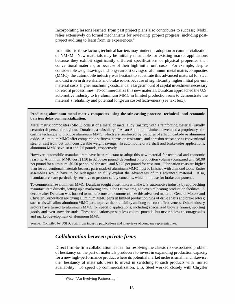
Producing aluminum metal matrix composites using the stir-casting process: technical and economicbarriers delay commercialization.
Metal matrix composites (MMC) consist of a metal or metal alloy (matrix) with a reinforcing material (usuallyceramic) dispersed throughout. Duralcan, a subsidiary of Alcan Aluminum Limited, developed a proprietary stir-casting technique to produce aluminum MMC, which are reinforced by particles of silicon carbide or aluminumoxide. Aluminum MMC offer comparable stiffness, corrosion resistance, and abrasion resistance as conventionalsteel or cast iron, but with considerable weight savings. In automobile drive shaft and brake-rotor applications,aluminum MMC save 18.0 and 7.5 pounds, respectively.
However, automobile manufacturers have been reluctant to adopt this new material for technical and economicreasons. Aluminum MMC cost $1.50 to $2.00 per pound (depending on production volume) compared with $0.90per pound for aluminum, $0.50 per pound for steel, and $0.20 per pound for cast iron. Fabrication costs are higherthan for conventional materials because parts made of aluminum MMC must be finished with diamond tools. Entireassemblies would have to be redesigned to fully exploit the advantages of this advanced material. Also,manufacturers are particularly sensitive to product-safety concerns, which limit use for brake components.
To commercialize aluminum MMC, Duralcan sought closer links with the U.S. automotive industry by approachingmanufacturers directly, setting up a marketing arm in the Detroit area, and even relocating production facilities. Adecade after Duralcan was formed to manufacture and commercialize this advanced material, General Motors andChrysler Corporation are trying aluminum MMC parts in limited production runs of drive shafts and brake rotors;such trials will allow aluminum MMC parts to prove their reliability and long-run cost-effectiveness. Other industrysectors have turned to aluminum MMC for specific applications, including specialized bicycle frames, sportinggoods, and even snow tire studs. These applications present less volume potential but nevertheless encourage salesand market development of aluminum MMC.
Source: Compiled by USITC staff from industry publications and interviews of company representatives.
Incorporating lessons learned from past project plans also contributes to success; Mobilrelies extensively on formal mechanisms for reviewing project progress, including post-project auditing to learn from its experiences.21
In addition to these factors, technical barriers may hinder the adoption or commercializationof NMPM. New materials may be initially unsuitable for existing market applicationsbecause they exhibit significantly different specifications or physical properties thanconventional materials, or because of their high initial unit costs. For example, despiteconsiderable weight savings and long-run cost savings of aluminum metal matrix composites(MMC), the automobile industry was hesitant to substitute this advanced material for steeland cast iron in drive shafts and brake rotors because of significantly higher initial per-unitmaterial costs, higher machining costs, and the large amount of capital investment necessaryto retrofit process lines. To commercialize this new material, Duralcan approached the U.S.automotive industry to try aluminum MMC in limited production runs to demonstrate thematerial’s reliability and potential long-run cost-effectiveness (see text box).
Collaboration between private firms—
Direct firm-to-firm collaboration is ideal for resolving the classic risk-associated problemof hesitancy on the part of materials producers to invest in expanding production capacityfor a new high-performance product where its potential market niche is small, and likewise,the hesitancy of materials users to invest in switching to such products with limitedavailability. To speed up commercialization, U.S. Steel worked closely with Chrysler

22 John Schriefer, “Increasing R&D’s Productivity,” New Steel, vol. 12, No. 6, June 1996, pp.72-78.
23 Torque tubes are aluminum and steel drive-shaft assemblies that are part of the controlsystem that raise and lower the flaps and slats on aircraft wings. The Grumman process extendsthe service life of the torque tube by strengthening the joint between the tube and fittings. Grumman has used electromagnetic forming for more than 20 years in the production of militaryaircraft, although this is the first commercial application of this technology. Grumman also offersthis process for automotive and other high-stress, rotary-motion applications. Anthony L.Velocci, Jr., “Ventures Rife with Marketing Pitfalls,” Aviation Week and Space Technology, vol.139, No. 19, Nov. 8, 1993, pp. 59-61.
24 John A.S. Green, John Brupbacher, and David Goldheim, “Strategic Partnering AidsTechnology Transfer, Martin Marietta Finds Technology Transfer Through Strategic Partnershipsa Rapid, Effective and Successful Tool for Developing Novel Engineered Materials,” ResearchTechnology Management, vol. 34, No. 4, July/Aug. 1991, pp. 26-31.
25 Ibid.
14
Corporation to fine-tune its newly developed steel sheet with an iron-zinc coating to becompatible with the latter’s painting system. In anticipation of a major market for its output,U.S. Steel could justify the expenditure for substantial modifications to itselectrogalvanizing process to produce the new iron-zinc steel sheet. Furthermore, the timespan from concept to full-scale manufacturing was 3 to 4 years, compared with 10 or moreyears to commercialize new products in the past.22
To side-step the time and expense of the earlier stages of the R&D process, private firmsmay elect to adopt innovations developed by outside sources in either a partially or fullycommercialized state. Two well-established mechanisms are licensing and strategicpartnerships. For a license-granting firm, licensing its technology can be an alternative toexpending resources to develop new markets and scale up to full commercial production.The mutual benefits attendant with licensing are illustrated by the Boeing Company’s 1993agreement with Grumman Corporation to apply Grumman’s patented electromagneticforming process for torque-tube joints in commercial aircraft, a deal that could be worth$10 million over the next 10 years.23
In a strategic partnership, two firms agree to share marketing and commercialization of aproduct or process created by one firm but developed by the other. This arrangementenables the originating firm to commercialize an innovation despite lack of technicalexpertise, skilled personnel, sufficient funding, or adequate capital equipment. MartinMarietta used a strategic partnership to commercialize high-strength aluminum alloys andmetal matrix composites, as the company’s core business is not materials production.24 Forthis case, important considerations for selecting a strategic partner were that the two firmsshould compete in different market segments and have similar organizational cultures, a highlevel of management commitment, a defined strategy to aggressively develop andcommercialize the technology, and the technical ability to work closely together. With bothlicensing and strategic partnerships, the acquiring firm receives access to a technologicalinnovation with less investment in R&D, but must finance fine-tuning the innovation forapplication, and must develop detailed marketing plans. A significant positive feature ofsuch partnerships is that commercial applications are developed concurrently with technicaldevelopment. For Martin Marietta’s technologies, markets may be already partiallydeveloped by strategic partners who are often major customers.25

26 Eagar, “Bringing New Materials to Market.”27 Schriefer, “Increasing R&D’s Productivity.”28 Potential annual energy savings for the U.S. steel industry anticipated from the six projects
are estimated at 16.5 trillion BTUs, which could cut costs to the industry by $103 million. Furthermore, potential NOx emissions could be cut by an estimated 13,000 metric tons, SOx by80,600 metric tons, and particulate matter by 33,100 metric tons. National Renewable EnergyLaboratory, Technology Partnerships, Enhancing the Competitiveness, Efficiency, andEnvironmental Quality of American Industry, for the U.S. Department of Energy, Office ofEnergy Efficiency and Renewable Energy, Office of Industrial Technologies, DOE/GO-10095-170 DE95004086 (Washington, DC, Apr. 1995).
29 Tim Stevens, “Success in Numbers: A Research Consortium Can Yield Big Payoffs toMember Companies, If They Do It Right,” Industry Week, vol. 243, No. 7, Apr. 4, 1994, pp. 45-48.
15
An alternative to adopting from outside a firm is pre-competitive collaboration with otherfirms. This approach to commercialize NMPM enables participants to spend R&D fundsmore efficiently and helps reduce duplication of expenditure and effort, especially in theearly phases of a project.26 Private firms may form horizontal consortiums to tackleproblems common to an entire industry, although the firms remain competitors in themarketplace. An increasing number of vertical consortiums are being formed among firmsfrom the various stages of production, as manufacturers increasingly interact with suppliersand customers to develop innovative technologies. For example, the 5-year AdvancedProcess Control Research Program, coordinated by the American Iron and Steel Institute,includes steelmakers, industry suppliers, and Federal laboratories27 collaborating in thedevelopment of advanced sensor and process-control technologies to improve steelmakingefficiency and reduce energy consumption and emissions.28 Factors for successfulconsortiums include long-term commitment and active participation of members (includingmanagement), access to members’ marketing and manufacturing capabilities, and afocused technology strategy.29 Furthermore, potential benefits are maximized with partnerswhose R&D capabilities are complementary.
Looking to R&D institutions as sources of innovativetechnologies—
Collaboration with Federal laboratories and research universities rather than competitorsmay be preferable to some firms, especially due to intense interfirm rivalries and problemsof sharing intellectual property rights. In addition, R&D institutions offer access totechnical expertise and advanced facilities that would be too expensive for most firms tobuild and operate (e.g., high-powered computational and sophisticated analyticalcapabilities).
The abilities of the 700+ Federal laboratories to develop and commercialize NMPMdepend to a great degree on the mission of the supporting agency and past experience. Anotable example is the extensive collaborative effort between the U.S. polymer industry andthe National Center for Agricultural Utilization Research to develop less expensive, moreversatile, advanced superabsorbent polymers. The results of this research not only enabledthe polymer industry to regain its domestic market share from foreign competitors, but alsoto enter new markets abroad (see text box). Although collaborative mechanisms rangefrom informal sharing of information (through laboratory publications, workshops andseminars, and technical consultations) to the use of Federal laboratory facilities, employee

30 Based on two surveys of chief technical officers and laboratory directors of industrial firmsby the Georgia Institute of Technology. There was less enthusiasm for licensing agreementsbecause many laboratory innovations needed further development at initial licensing to bring themto commercial success. Cited in: David Hughes, “Industry Seeks Expertise in Federal LabInteraction,” Aviation Week & Space Technology, vol. 139, No. 19, Nov. 8, 1993, pp. 56-58; andJ. David Roessner and Alden S. Bean, “How Industry Interacts with Federal Laboratories,”Research Technology Management, vol. 34, No. 4, July/Aug. 1991, pp. 22-25.
31 Both partners provide relatively equal amounts of resources (facilities, equipment,personnel, expertise, and funding) to the agreement, but the Federal laboratory cannot provideappropriated funds. Dan Cordtz, “Bye-Bye, Dr. Strangelove, Threatened with Extinction byPoliticians, U.S. Weapons Labs are Dying to Help Business,” Financial World, vol. 164, No. 2,Jan. 17, 1995, pp. 32-37.
32 From quarterly surveys of its CRADA partners, Sandia National Laboratory found that theprogram was responsive to industry queries, and technical goals and milestones were being met,but the time required to conclude agreements needed to be reduced. William B. Scott,
(continued...)
16
Superabsorbent starch-based polymers: commercializing Federal laboratory innovations for revival andexpansion of domestic industry.
Superabsorbent polymers are used in air filters, to mop up spills and absorb wastes, to reduce watering requirementsof crops, and in numerous products in the construction, electrical, petroleum, and chemical industries. The specificabsorbency of polymers allows some mixed liquids to be readily separated, for example, extracting water from dieselfuel or gasoline.
In the 1980s, the U.S. polymer industry was losing its market share to foreign competition in the $1-billion-a-yeardomestic market, particularly to producers of petroleum-based synthetic absorbents. Scientists at the Departmentof Agriculture’s National Center for Agricultural Utilization Research (NCAUR) revisited past research and reliedupon extensive links with industry to identify existing and potential applications; product performance requirements;and production, equipment, and market needs. Industry engineers and researchers were invited to observe andcomment during laboratory preparation of the polymer, and NCAUR scientists collaborated with industry to resolvetechnical problems during scale-up to commercial production.
This public-private collaboration resulted in improved starch-based polymers that are more absorbent, effective fora broader range of substances, and less expensive than other absorbent polymers. As a result, the domestic polymerindustry regained its standing in the domestic market, and opened new markets as U.S. manufacturers began sellingoverseas.
Source: George Fanta and William Doane, “Researchers Starch Up Soggy U.S. Polymer Industry,” Winners in TechnologyTransfer (Federal Laboratory Consortium for Technology Transfer, Washington, DC, 1994).
exchanges, and licensing, three mechanisms were most frequently cited as promising futurepayoffs: industry-sponsored research, contract research, and cooperative R&D.30
The use of cooperative research and development agreements (CRADAs) hasmushroomed since their inception in 1986 because of unique advantages over other formsof industry-Federal laboratory collaboration. These advantages include exclusiveownership of patent rights for the industrial partner, protection of proprietary information,and royalty shares for government researchers. To some critics, the CRADA program is toogenerous to industrial partners who essentially pay half the R&D costs,31 and some industryofficials have criticized the long delays for CRADA approval.32 In contrast, supporters have

32(...continued)“Technology Transfer Support Wavers,” Aviation Week & Space Technology, vol. 143, No. 17,Oct. 23, 1995, pp. 57-60.
33 Charryl Berger, deputy director of the Los Alamos National Laboratory IndustrialPartnerships Office, cited in: Cordtz, “Bye-Bye, Dr. Strangelove.”
34 Robert Killoren, “University-Industry Interactions, Room for Diversity,” SRA Journal, vol.25, No. 2, June 1994, pp. 31-35.
35 Federal-agency programs encouraging U.S. industry to innovate were reviewed inAbrahamson, “New Manufacturing Processes for Materials: Government Policies and ProgramsTowards Commercialization.”
36 U.S. Congress, OTA, Innovation and Commercialization of Emerging Technologies.37 Paul Proctor, “Regional Agencies Help Small Firms Get Foothold,” Aviation Week & Space
Technology, vol. 143, No. 17, Oct. 23, 1995, p. 62.38 Based on a study of survey results from 120 small manufacturing firms in middle
Tennessee. John Masten, G. Bruce Hartmann, and Arief Safari, “Small Business StrategicPlanning and Technology Transfer, the Use of Publicly Supported Technology AssistanceAgencies,” Journal of Small Business Management, vol. 33, No. 3, July 1995, pp. 26-37.
17
questioned the wisdom of firms paying the entire cost, which would reportedly turnlaboratories into “job shops,” a shortcoming the CRADA program was designed todiscourage.33
Industry also has a long history of interaction with research universities. Althoughuniversities are capable of long-range basic research, it is on a relatively small scalecompared with the Federal laboratories, and is usually confined to specific academicdisciplines. These factors, plus academia’s emphasis on freedom of inquiry, can beproblematic in meeting private industry’s need for multi-disciplinary, applied R&Dassistance. To bridge these cultural differences, many academic institutions havedeveloped technology transfer centers to coordinate and facilitate customized assistance.This type of collaboration is most common for incremental improvements to existingtechnologies or products.34
Taking advantage of government technology-commercializationprograms—
At all levels of government, there are programs to promote the transfer of technology fromR&D institutions to private industry, particularly to small- and medium-size business.35 Atthe state and local level, for example, there are some 390 technology-commercializationprograms.36 These vary in structure, focus, and range of services, from providing technicalassistance to small businesses, promoting industry collaborations, and offering literaturesearch capabilities, to financing small businesses and giving start-up assistance to smalltechnology-based firms or regional industries. Despite successes, these efforts reportedlyare sometimes criticized not only for lacking expertise, but also for wasting funds becauseof inefficiencies, program overlap, and bureaucratic snarls.37 Awareness of localtechnology-commercialization resources was reported to be low among smallmanufacturers, but use increased with extent of prior use.38 It also has been reported thatsmall firms generally are in greater need of “off-the-shelf” technologies, particularly

39 William H. Miller, “Federal Help, Don’t Laugh, The Commerce Dept’s. Expanding Systemof Manufacturing Technology Centers is Trying to Show That the Feds Can be Useful,” IndustryWeek, vol. 242, No. 14, July 19, 1993, pp. 55-61.
40 Materials Advisory Board, Commercialization of New Materials for a Global Economy.41 Eager, “Bringing New Materials to Market.”42 Ibid.43 Materials Advisory Board, Commercialization of New Materials for a Global Economy.44Office of Science and Technology Policy, Total Materials Cycle, the Pathway for
Technology Advancement.45 Eager, “Bringing New Materials to Market;” and National Materials Advisory Board,
Commercialization of New Materials for a Global Economy.
18
computer-aided drafting and manufacturing software, and applying computerizedtechniques to the factory floor for statistical process control and inventory control.39
Outlook: Further Actions for Effective Commercializationof NMPM
Despite considerable progress toward commercializing innovative materials technologies,observations of key participants in the process suggest that continued efforts are needed topromote development and adoption of NMPM. Standards for test methods and materialsdesign should be developed,40 taking into account factors such as increased performance ofadvanced materials and degree of risk for the application. For example, given the stronger,more fracture-resistant steels that are now readily available, materials specifications forpressure-vessel boilers are currently over-specified, being nearly the same as they were 50years ago.41 In those cases where a single firm cannot afford to underwrite extensive testingof an advanced material, pooling the cost of risk assessment may be helpful.42 Evaluationof NMPM also could be improved by increased standardization of design-related, materials-property databases.43 For certain materials R&D areas that are seldom tied directly tocommercial applications, it is reported that the government may need to take the lead,especially in supporting research to characterize and understand new materials, and indeveloping advanced computational tools for new-material design methods, and life-cycleperformance analysis techniques.44
For private industry, reported recommendations focus on developing and expandingmarkets for advanced materials.45 Collaborations to tailor an advanced material to meetspecific end uses and increase production and market capacity include:
C Establishing direct links with the ultimate end users of a materialrather than just the immediate customer.
C Increased mutual sharing of proprietary technical information andmarketing strategies between materials suppliers and users. Also,increased joint ventures between materials suppliers and users.
C Incremental introduction strategies to improve existing products andbuild market demand for an advanced material.

46 Allaire, Sheinkman, and Everhart, Endless Frontier, Limited Resources.47 National Materials Advisory Board, Commercialization of New Materials for a Global
Economy. Private firms also impose barriers deliberately for strategic considerations, especiallyto preserve trade secrets and protect economically valuable innovations from competitors. Likewise, foreign economic rivals also screen the acquisition of economically valuableinnovations by U.S. firms.
48 Brody, Effective Partnering.49 National Materials Advisory Board, Commercialization of New Materials for a Global
Economy; and Brody, Effective Partnering.
19
Extremely fine metallic-membrane filters: posing a $2 billiondual-use technology dilemma.
Martin Marietta was interested in applying metallic membranetechnology to commercial filtration applications ranging from effluenttreatment to purification of orange juice, with an estimated potentialof $2 billion in commercial business by 2000. This technology hasbeen developed by Oak Ridge National Laboratory for use asextremely fine filters in the gaseous diffusion process for purifyinguranium. Declassification of this technology was halted by concernsabout the Iraqi government’s efforts to upgrade its nuclear processingcapabilities.
Source: Thomas G. Donlan, “The Price of Progress, Scientific AdvancesRequire Sound Investment Policies and Clear Goals,” Barron’s, vol. 74, issueNo. 26, June 27, 1994, p. 62.
To the extent that partnerships with private industry continue, results reportedly can beimproved through a number of specific policy changes by the Federal Government:
C Improve the continuity of Federal R&D resources to reduce fiscalunpredictability.46
C Reform export-control regulations on dual-use technologies thatmay unnecessarily interfere with interactions between U.S. firms andforeign partners, restrict access to foreign technical bases, or limitU.S. firms’ access to international markets (see text box).47
C Improve the speed, flexibility, and predictability of negotiating,implementing, and funding industry partnership agreements withFederal laboratories.48
C Promote timely and wide dissemination of information on Federallyfunded innovations and R&D partnership opportunities49 byestablishing a centralized materials database.

50 Allaire, Sheinkman, and Everhart, Endless Frontier, Limited Resources; and NationalMaterials Advisory Board, Commercialization of New Materials for a Global Economy.
51 Lewis M. Branscomb, Aetna Professor Emeritus of Public Policy and CorporateManagement Center for Science and International Affairs, John F. Kennedy School ofGovernment, Harvard University, Testimony, Hearing of the Subcommittee on Science,Technology and Space of the Senate Committee on Commerce, Science and Transportation, Apr.16, 1997.
52 Federal partnerships with State programs are essential because states are much closer to thepractical need of local businesses through the efforts of State colleges and universities and Statecommerce and transportation agencies. At their 1997 meeting in Washington, DC, the StateGovernors created a formal structure for linking Federal and State research teams in partnership. John H. Gibbons, Assistant to the President for Science and Technology, Technology Partnering: Can You Count on the Government? (Federal Technology Report, McGraw-Hill Companies, Inc.,Washington, DC, Mar. 3, 1997).
53 Brody, Effective Partnering.54 Walter H. Plosia, Executive Director, North Carolina Alliance for Competitive
Technologies, “State and National Strategies for Promoting Innovation and Stimulating EconomicDevelopment,” Trends in Industrial Innovation, Industry Perspectives and Policy Implications,1997 Sigma Xi Forum, Arlington, VA, Nov. 20-21, 1997.
55 Allaire, Sheinkman, and Everhart, Endless Frontier, Limited Resources; and NationalMaterials Advisory Board, Commercialization of New Materials for a Global Economy.
56 Branscomb, Testimony, Hearing of the Subcommittee on Science.
20
C Pare agency bureaucracies and decentralize decision making toallow laboratory directors to implement their own strategies and beaccountable for supporting commercial applications.50
C Increase partnerships with small- and medium-sized technologyfirms.51
C Coordinate Federal programs with State programs,52 especially toimprove the effectiveness of small business in commercializinginnovative NMPM53 and to reduce overlap in State programs.54
For research universities, reported recommendations specific to NMPM focused ondisseminating updated knowledge about advanced materials:55
C Include advanced-materials selection and design in the materialsengineering curriculum.
C Promote continuing education for materials engineers ontechnological advancements and practice-oriented training formaterials technicians.
C Promote programs for faculty and graduate students to gainexperience in industrial laboratories as a means of promoting linksbetween university and private-sector R&D.
C Increase partnerships with small- and medium-sized firmsspecializing in technology.56

21
Private industry, government, and academia continue to commercialize innovative NMPMin response to economic and regulatory incentives. The numerous interactive and ofteninterlinked approaches devised by these participants have evolved through time to addressmany of the barriers that impede development and adoption of such innovativetechnologies. The extent to which the above suggestions can be implemented will havesignificant bearing upon the pace of technological innovation, which, in turn, impactsindustrial competitiveness in a rapidly changing and increasingly globalized marketplace.

22
Glossary of TermsConsortium A joint R&D agreement among private firms to develop a technology of
common interest to participants. Government agencies and researchuniversities also may participate in or organize such ventures.
Cooperative researchand developmentagreement (CRADA)
A formalized joint R&D agreement between private industry (either a singlefirm or multiple firms) and a Government agency, national laboratory, orresearch university.
Defense conversion Reorienting an institution’s R&D efforts from defense-related to commercial,non-defense-related applications.
Dual-use technology Innovations with both commercial and military applications.
External acquisition oftechnology
Innovations brought into a firm from an outside source. Also referred to as“technology acquisition.” Contrast with internal technology development.
Horizontal consortium An industry consortium whose member firms normally compete in the sameor related markets. Contrast with vertical consortium.
Internal technologydevelopment
Innovations developed by a firm from within, through successive functionalunits involved in the R&D process. Contrast with external acquisition oftechnology.
Licensing An agreement granting an acquiring firm access to the licensor’stechnology.
Market pull Technology development spurred specifically when a solution is sought bythe market to meet an existing technical need. Contrast with technologypush.
New manufacturingprocesses formaterials (NMPM)
Any manufacturing process that can produce materials more efficiently thancan conventional processes, or can produce materials with superiorproperties compared with conventional materials, or both. NMPM alsocould result in entirely new materials.
Strategic partnership A joint R&D agreement between two private firms to commercialize atechnology initially developed by one, but in need of further development bythe other to bring the technology to the marketplace.
Technology push Technology for which there is currently no commercial market, butdevelopers seek commercial applications after its development is underway or completed. Contrast with market pull.
Vertical consortium An industrial consortium whose members do not all compete in the same orrelated marketplaces, but rather are drawn from the various stages ofproduction (e.g., materials suppliers, finished-product manufacturers, etc.). Contrast with horizontal consortium.

1Within the United States, the National Critical Technologies Panel (appointed by the Officeof Science and Technology Policy (OSTP)), the Department of Commerce, and the Council onCompetitiveness (a private organization of representatives from business, higher education, andlabor) have all identified materials and associated processing technologies as critical for U.S.competitiveness and economic prosperity. Report of the National Critical Technologies Panel(Washington, DC: Office of Science and Technology Policy), Mar. 22, 1991; U.S. Department of
(continued...)
23
New Manufacturing Processes for Materials:Government Policies and Programs TowardsCommercializationDana AbrahamsonCheryl Badra Qassis(202) [email protected]
This article examines the Government’s increasing involvement inresearch and development activities, with a particular focus on thedevelopment and eventual commercialization of advancedmaterials and processing technologies. Since the early 1990s, theadministration has emphasized Government-industry cooperationin technology development as an important priority. Indeed,several mechanisms have been established to facilitatecooperation between the private and public sectors. In addition,significant legislation has been passed promoting technologytransfer that has benefited the development of advanced materialsand processing technologies. Finally, the article discusses severalfactors that will likely impact Government involvement in suchactivities in the future.
Since this article was first published in the Industry, Trade, andTechnology Review of March 1995, policy mechanisms directingGovernment coordination of materials R&D have been phasedout. However, budget allocations to the relevant agencies have notdecreased significantly, suggesting that materials developmentefforts supported by the Federal Government will continuerelatively unhindered. In addition, there has been significantlegislative activity supporting R&D efforts that could affect theGovernment’s R&D activities in materials. The concludingsection of this article elaborates on recent developments andprovides current funding estimates for certain programs.
The development of advanced materials and processing technologies directly affect anation's economic prosperity, environmental health, and quality of life. The importance ofthese related areas has been highlighted by numerous U.S. and foreign government andprivate studies, all of which have reached similar conclusions.1 Materials processing

1(...continued)Commerce, Emerging Technologies: A Survey of Technical and Economic Opportunities(Washington, DC: U.S. Department of Commerce), Spring 1990; and The Council onCompetitiveness, Gaining New Ground: Technology Priorities for America's Future(Washington, DC: The Council on Competitiveness), Mar. 1991.
2Committee on Science, Engineering, and Public Policy, The Government Role in CivilianTechnology: Building a New Alliance (Washington, DC: National Academy Press, 1992).
3 In addition, Offices of Research and Technology Applications (information offices onlaboratory products and services) were established in every national lab.
24
technology is a vital enabling technology; with each advancement, the potential for advancesin other fields increases. This is because advances in processing technologies can result inincreased efficiency and productivity, lower production costs, and improved materialcharacteristics. This article examines the role the U.S. Government plays in thedevelopment and precommercial stages of materials-processing technologies, outliningshifts in government focus, the framework for government involvement, and the outlook forfuture government involvement.
Shifts in Government Focus
The U.S. Government has a long history of involvement in the materials and materials-processing fields. For many years, Federal research and development (R&D) efforts inthese areas centered on defense- and space-related technologies used by the Department ofDefense and the National Aeronautics and Space Administration (NASA). Advances inmilitary and space systems often require the use of new materials or new processingtechniques where unique combinations of properties or specific characteristics are necessary.As the principal consumer of military and aerospace technologies, the U.S. Government hasa vested interest in their development. As a result, the Government has been willing tounderwrite the risk and expense involved in developing these areas.
In the post-Cold War era, military threats have decreased and concerns about economiccompetitiveness have become increasingly important. Accordingly, the U.S. Governmenthas, to a degree, shifted its focus from development of defense-related technologies todevelopment and transfer of technologies applicable in the commercial sector as well. Inaddition, a trend towards greater cooperation and coordination of public/private efforts isbeing embodied in current initiatives.
This recent administration's increased emphasis on technology transfer andgovernment-industry cooperation has been a continuation of legislative initiatives enactedsince the 1980s (figure 1).2 Relevant statutes include the Stevenson-Wydler TechnologyInnovation Act (1980), which formally made technology transfer a policy of the FederalGovernment by mandating that 0.5 percent of each national lab budget be spent ontechnology transfer;3 the Patent and Trademark Amendments Act (1980), which gaveFederal agencies authority to grant licenses to small businesses and nonprofit organizations(including universities) for inventions made at government- and contractor-operatednational labs; and the National Cooperative Research Act (1984), which limited thepotential application of antitrust laws in order to foster cooperative research amongcompanies.

25
Figure 1
since the 1980s
1990s
1980s
Source: Compiled by USITC staff.
1989 Public Law 101-189 NationalCompetitiveness Technology Transfer Act
1986 Public Law 99-502 FederalTechnology Transfer Act
1984 Public Law 98-462 NationalCooperative Research Act
1980 Public Law 96-517 Patentand Trademark Amendments Act(Bayh-Dole)
1980 Public Law 96-480 Stevenson-Wydler TechnologyInnovation Act
1993 Public Law 103-42 NationalCooperative Production Amend-ment
1992 Public Law 102-564 SmallBusiness Research andDevelopment Enhancement Act
1991 Public Law 102-245 American TechnologyPreeminence Act
Legislative initiatives promoting technology transfer enacted

4Clinton, William J., and Albert Gore, Jr., Technology for America's Economic Growth, ANew Direction to Build Economic Strength (Washington, DC, Feb. 22, 1993).
5Office of Science and Technology Policy, Advanced Materials and Processing: The FiscalYear 1994 Federal Program (Washington, DC: Office of Science and Technology Policy, July1993), p. 6.
26
More recently, the Federal Technology Transfer Act (1986) amended theStevenson-Wydler Act, delegating authority to national labs to enter into cooperativeresearch and development agreements (CRADAs) with non-Federal parties (i.e., privatebusinesses). The National Competitiveness Technology Transfer Act (1989) includedtechnology transfer in the mission of the national labs. Further, the American TechnologyPreeminence Act (1991) aimed to strengthen programs promoting U.S. economiccompetitiveness at the various agencies. The Small Business Technology Transfer Act(1992) outlined specific rules for technology transfer. And finally, the NationalCooperative Production Amendment (1993) amended the National Cooperative ResearchAct, further modifying antitrust laws to increase research joint ventures in the privatesector. In addition, many Federal agencies have specific legislation governing technologytransfer.
Framework for Government Involvement
As part of the U.S. Government's new focus on technology, in 1993 the Clintonadministration enunciated a new emphasis on public/private cooperation in technologydevelopment.4 Federal agencies are to facilitate civil technology development inprecommercial areas, to foster cooperative efforts between the Government and theprivate sector, and to transfer new technologies developed in Government facilities to allsectors of the economy. These changes are expected to increase the ability of privateindustry to leverage its R&D expenditures with Federal monies as well as to gain access tothe vast array of technology already under development at the national labs. Moreover, theU.S. Government will be able to leverage taxpayer funding of the national labs with privateR&D expenditures.
This change in emphasis was formally stated in Advanced Materials and Processing: TheFiscal Year 1993 Program (AMPP), a supplement to the President's budget request forfiscal year 1993. The AMPP provides a framework to promote interaction and cooperationamong all players in the technology development field (government, industry, anduniversities) and to facilitate the progression from technology innovation to application.One stated goal of the AMPP is to improve the performance and manufacture of materials toenhance the quality of life, security, industrial productivity, and economic growth in theUnited States.5 Agencies participating in the AMPP and significantly involved in materialstechnology include the Department of Commerce, Department of Defense, Departmentof Energy, Department of the Interior, Department of Transportation, EnvironmentalProtection Agency, Department of Health and Human Services, NASA, National ScienceFoundation, and Department of Agriculture. Table 1 lists AMPP funding levels for theseagencies.

6Gore, Albert, Jr., "From Red Tape to Results: Creating a Government that Works Better &Costs Less," Report of the National Science Foundation and Office of Science and TechnologyPolicy (Washington, DC: Office of the Vice President), Sept. 1993, p. 5.
7Clinton, William J., and Albert Gore, Jr., Technology for America's Economic Growth, ANew Direction to Build Economic Strength (Washington, DC, Feb. 22, 1993), p. 8.
8According to the Stevenson-Wydler Act (1980), 0.5 percent of each national lab budget wasallocated to technology transfer activities.
9Clinton, and Gore, Technology, Washington, DC, Feb. 22, 1993, p. 9.
27
Table 1Funding levels under the Advanced Materials Processing Program, 1992-94
(Million dollars)
Agency 1992 1993 1994
Department of Agriculture . . . . . . . . . . . . . . . . . . . . . . . . . . . . . 36.3 37.4 45.8Department of Commerce . . . . . . . . . . . . . . . . . . . . . . . . . . . . 2.6 48.4 56.7Department of Defense1 . . . . . . . . . . . . . . . . . . . . . . . . . . . . . . 530.9 557.7 421.7Department of Energy1 . . . . . . . . . . . . . . . . . . . . . . . . . . . . . . . 862.5 914.0 941.5Department of the Interior . . . . . . . . . . . . . . . . . . . . . . . . . . . . . 5.2 24.9 21.5Department of Transportation . . . . . . . . . . . . . . . . . . . . . . . . . . 1.0 14.9 12.7Environmental Protection Agency . . . . . . . . . . . . . . . . . . . . . . 0.5 4.5 4.5Health and Human Services . . . . . . . . . . . . . . . . . . . . . . . . . . . 79.6 85.9 92.9National Aeronautics and Space Administration . . . . . . . . . . . 76.3 102.8 131.1National Science Foundation . . . . . . . . . . . . . . . . . . . . . . . . . . 265.6 303.6 328.0 Total . . . . . . . . . . . . . . . . . . . . . . . . . . . . . . . . . . . . . . . . . . 1,933.5 2,094.1 2,056.4
1 This figure does not include classified research and development activities.
Note.--Data for 1992 are actual expenditures, 1993 are congressional appropriations, and 1994 are the President's budget request.
Source: Office of Science and Technology Policy, Advanced Materials and Processing: The Fiscal Year 1994 Federal Program(Washington: Office of Science and Technology Policy, 1993), p. 13.
During 1994, the U.S. Government allocated over $75 billion in R&D expenditures.6 Of thetotal budget, approximately 60 percent was allocated to military and defense technologyprojects, with the remaining 40 percent directed at civilian or commercial projects.However, with the shifting focus to economic competitiveness, the administration hasstated that it would like to see this ratio reach 50-50 by 1998.7 To reach this goal, agenciesare increasing their outreach programs to the private sector and developing a wide rangeof mechanisms to facilitate public-private partnerships.
The national labs affiliated with the various Federal agencies offer private industry R&Dprojects a source of funding, research, and technical advice. There are over 700 nationallabs, which spend $35 billion to $40 billion annually on research and developmentefforts, with generally 5 to 10 percent spent in R&D partnerships with industry.8 Theadministration has stated that this portion should be increased to 10 to 20 percent of thebudget of each laboratory.9
A wide range of mechanisms are available to facilitate public-private partnerships. Theyinclude personnel exchanges, data exchange agreements, use of specialized facilities,cost-shared procurement, cooperative agreements, patent and software licensing,

10Additional information about CRADAs and other technology transfer mechanisms isavailable from a number of sources including DOE and DOC, and is summarized in DOE’s“Technology Transfer Quick Reference: Technology Transfer Mechanisms.”
11More detail on the PNGV is available from the Department of Commerce.12Stockdale, Grant, president, Technology Publishing Group, Washington, DC, USITC phone
conversation, Jan. 20, 1995.13Department of Energy, Washington, DC.
28
reimbursable work for others, technical assistance, and cooperative research anddevelopment agreements.
CRADAs represent one of the main mechanisms for technology transfer from theFederal agencies and nationals labs to the private sector.10 Under a CRADA, one or moreFederal agencies, through its laboratories, may provide personnel, services, facilities,equipment, or other resources (not including funds), with or without reimbursement, toone or more non-Federal parties. In turn, private parties may provide funds, personnel,services, facilities, equipment, or other resources toward the conduct of specified R&Dthat is consistent with the laboratory missions. CRADAs are designed to limit paperworkrequirements and to allow flexible implementation. For example, agencies can streamlineprocedures or shorten approval times, which can range from a few weeks to over 18months, and have some discretion in entering any agreement.
Legislation encouraging industry to participate in CRADAs includes an exemption forparticipating parties from antitrust regulations, thereby allowing large segments of anindustry to cooperate in Federally funded research efforts. For example, the Partnershipfor New Generation Vehicles (PNGV) is an initiative between the U.S. Government andthe "Big Three" auto manufacturers (General Motors, Ford, and Chrysler) that focuses ondeveloping a new generation of fuel-efficient vehicles. The Government part of thepartnership is an interagency effort headed by the Department of Commerce and includesthe Departments of Defense, Energy, and Transportation, the Environmental ProtectionAgency, NASA, and the National Science Foundation.11
In addition, CRADA legislation allows private entities to obtain rights to intellectualproperty developed within a CRADA while protecting any existing patents a companyor lab brings to the project. Moreover, the Federal Technology Transfer Act establishedroyalty sharing for Federal inventions and directed agencies to promote technologytransfer via a cash awards incentive program for Federal employees.
As of December 1, 1994, 3,220 CRADAs were signed, partnering private industry withnational laboratories.12 The number of CRADAs has increased dramatically in the lastfew years. For example, as of January 1, 1993, the Department of Energy had 329CRADAs with private industry. However, by January 1, 1995, this number had risen to1,157, with a value of $2.1 billion (of which industry contributions accounted for 57percent).13
Examples of CRADAs in the materials processing area include gel casting and precisionaluminum forming. The Oak Ridge National Laboratory has signed several CRADAsinvolving its gel casting technology, including one with AlliedSignal and another with

14Gel casting involves creating a gel with ceramic material that is then able to be poured into amold and hardened. This process allows more intricate parts to be made and has the potential toreduce manufacturing costs of forming ceramic parts.
15USITC phone interview, representative of Oak Ridge National Laboratory, Oak Ridge, TN.16Lawrence Livermore National Laboratory, Industrial Partnerships-The Dual Benefit Story,
Livermore, CA, Oct. 1994.17National Research Council, Commercialization of New Materials for a Global Economy
(Washington, DC: National Academy Press, 1993), p. 21.18National Materials Advisory Board, "Commercialization of New Materials for a Global
Economy" (Washington, DC: National Research Council), 1993, p. 15; and John T. Schofield,Chairman and CEO of Thermatix, Inc., U.S. Department of Energy, background paper onUnderstanding "Valley of Death" issues in Federal R&D (Washington, DC: U.S. Department ofEnergy), Dec. 5, 1994.
29
Ceramic Magnetics.14 In both cases, the companies are providing design and fieldtesting, while Oak Ridge is tailoring its original process technology to each company'sneeds.15 The Lawrence Livermore National Laboratory and Sandia NationalLaboratories have partnered with the Aluminum Company of America (ALCOA) to jointlyadvance the state-of-the-art in computational analysis of aluminum-forming processes.This development has the potential to reduce manufacturing costs and improve productquality, both of which can reduce the life cycle costs for a variety of U.S. industrialproducts.16
Agencies are also implementing outreach programs, designed to inform the private sectorof what facilities and resources are available. Outreach programs include agencyparticipation in trade shows, conferences, expositions, and professional society meetings.In addition, several agencies, including NASA, the Department of Energy, and theDepartment of Defense, have established databases to assist industry with problems andprovide information about available technology and Federal resources. Table 2 outlinesthe technology transfer mechanisms used by the various agencies.
Outlook for Future Government Involvement
The National Research Council regards faster commercialization of materials technologyas critical to ensure U.S. Government ability to specify and procure advanced militaryand space systems, to obtain maximum benefits from available materials technologies atcosts equivalent to those in commercial production, to enhance the competitiveness of theU.S. industries, and to extend U.S. technological leadership.17
The commercialization process can be divided into several phases or stages, includingbasic research/idea development; exploratory development or initial concept validation;pilot development; prototype development; application/demonstration; and commercialuse.18 U.S. Government funding generally is limited to the early stages because of legalconstraints and the traditional government policy of limiting involvement in businesseconomic-decision making (figure 2).
The new Agreement on Subsidies and Countervailing Measures in the Uruguay RoundAgreement (URA), establishing the World Trade Organization (WTO), addressesgenerally the subject of subsidies and the remedies that WTO members may take

30
Table 2Agency involvement in materials processing R&D and technology transfer
Agency Processing Research and Technology Transfer
Department of Commerce,National Institute of Science &Technology (NIST)
Carried out in 7 labs, particularly the Materials Science and Engineering Lab (MSEL);MSEL has major programs in advanced ceramics, advanced heat engines, andpolymermatrix composites. NIST promotes technology transfer via CRADAs and outreachactivities.
Department of Defense (DOD) Carried out by the Army, Navy, Air Force, and the Advance Research Projects Agency(ARPA). Research efforts are geared to providing future military systems, however, dual-useapplications of defense technologies are encouraged. Technology transfer occurs primarilythrough the hundreds of DOD-supported university research centers.
Department of Energy (DOE) DOE has the largest program among the 10 agencies, ranging from fundamental research todemonstrations of materials fabrication technologies. Technology transfer is facilitatedthrough direct grants, research collaboration, industrial use of DOE facilities, CRADAs, andoutreach activities.
Department of the Interior (DOI) Materials R&D is carried out through the Bureau of Mines (BOM) and is focused onenvironmental and conservation issues related to engineered and commodity materials. Technology is transferred via CRADAs and Memorandums of Understanding (MOU) inaddition to outreach programs.
Department of Transportation(DOT)
Materials R&D is supported by the Coast Guard, the Federal Aviation Administration, andthe Federal Highway Administration. Projects are usually directed at transportationtechnologies. Nearly all DOT research is publicly disseminated because DOT mustcoordinate its activities with state and local governments and the transportation industry. Inaddition, DOT provides opportunities for joint research activities with industry anduniversities.
Environmental Protection Agency(EPA)
Research efforts in materials and materials processing are directed at improving theenvironment. Research is carried out by the Risk Reduction Engineering Laboratory(RREL) and the Air and Energy Engineering Research Laboratory (AEERL). Both labswork closely with industry, via CRADAs and licensing agreements.
Department of Health andHuman Services (HHS)
Materials R&D is carried out by 12 units of the National Institutes of Health (NIH) and bythe Food and Drug Administration (FDA), focusing on improving biomaterials andbimolecular materials for use in medical device implants. HHS maintains extensivecommunication with academia and industry as most NIH research is conducted by outsideinvestigators via grants and contracts.
National Aeronautics and SpaceAdministration (NASA)
NASA materials research revolves around developing advanced materials and processes foruse in engines and airframe structures. Technology is mainly transferred through closecooperation with the U.S. aerospace industry. In addition, there is the TechnologyUtilization Program which fosters liaisons with industry and produces publications. Finally,NASA reaches out to universities and small businesses through its network of 10 university-affiliated Industrial Application Centers and 12 Centers for the Commercial Development ofSpace.
National Science Foundation(NSF)
NSF materials research centers on the synthesis of new materials, fundamental principles,novel and creative approaches to materials processing, applying basic knowledge tomaterials, and training future scientists and engineers in materials research and processing. NSF transfers technology via projects at multi-user research facilities, which reach out toindustry and national labs to optimize the application of new fundamental knowledge. Inaddition, NSF promotes technology transfer by training students for careers in materialsscience.
Department of Agriculture(USDA)
Materials research at USDA is carried out by the Forest Service, the Agricultural ResearchService, and the Cooperative State Research Service. Research activities focus on the use ofrenewable, nonfood agricultural materials and their derivatives in industrial processes andproducts. USDA transfers technology primarily through CRADAs and by working directlywith the private sector at the point of commercialization of industrial uses of agriculturalproducts, with emphasis on advanced materials.
Source: Office of Science and Technology Policy, Advanced Materials & Processing: The Fiscal Year 1994 Federal Program,Washington, DC, July 1993.

31
Government involvement
Time
Stages of commercialization and government involvement
Source: National Materials Advisory Board and John T. Schonfield, Chairman and CEO of Thermatix, Inc.

19The agreement for the first time defines the term subsidy and creates three categories ofsubsidies: (1) prohibited subsidies; (2) subsidies that may be challenged in WTO disputesettlement proceedings and domestically countervailed if they cause adverse trade effects; and (3)nonactionable and noncountervailing subsidies, if they are structured according to criteriaintended to limit their potential for causing trade distortions.
20Agreement on Subsidies and Countervailing Measures, Final Agreement Embodying theResults of the Uruguay Round of Multilateral Trade Negotiations, part IV, article 8, 1994.
21Department of Energy, "Our Commitment to Change: A Year of Innovation in TechnologyPartnerships" (Washington, DC: Department of Energy), Sept. 1994, p. 13.
22Linda Cohen, “Political Economy and Public Policy: When Can Government SubsidizeResearch Joint Ventures? Politics, Economics, and Limits to Technology Policy,” AmericanEconomic Review, Vol. 84, Issue 2, May 1994, pp. 159-163.
23Larry Reynolds, “Technology Policy Breeds New Era of Cooperation,” ManagementReview, Jun. 1993, pp. 50-52.
32
against foreign subsidization.19 For example, under the General Agreement on Trade andTariffs (GATT), the U.S. Government can fund only up to 50 percent of the costs ofspecific precompetitive development activity, defined as "the translation of industrialresearch findings into a plan, blueprint or design for new, modified or improved products,processes or services whether intended for sale or use, including the creation of a firstprototype that would not be capable of commercial use."20 In other words, Federalfunds can be used for first prototypes or models that cannot be used commercially, butnot specific direct funding of commercial-ready applications. However, due to such legalconstraints, government involvement usually stops short of direct commercializationassistance. Technology is transferred and/or manufacturing problems are ironed out, butthe private sector bears responsibility for finding capital, researching markets, developingbusiness plans, advertising, and sales.
Despite these restrictions, government funding in precommercial stages can benefitprivate industry and impact the U.S. economy as a whole, through expansion anddissemination of basic science and knowledge, job creation, increased industrial output,and improvements in energy efficiency and the environment. Congress and policymakers are increasingly holding agencies to these goals, leading many agencies todevelop measures to track the benefits of technology transfer. For example, a recent studylooked at the economic benefits derived from many of the Department of Energy'saward-winning technologies developed from 1989-1992. The study found that, of the 113technologies surveyed, 46 percent had transferred technology to the private sector; 10percent resulted in a new company being formed; 52 percent have created jobs; 22 percenthave saved jobs; 12-24 percent have resulted in notable energy savings; and 20-40percent have resulted in notable environmental improvements.21
However, policy makers, academia, and the private sector continue to debate theproper role of government in R&D and the business arena, and the best way to achievegovernment goals.22 Proponents of involvement contend that without increasedgovernment funding of technology development, within constraints of the subsidiesagreement of the URA, U.S. industries are at a disadvantage and thus less competitiveglobally. A contrasting view is that investment in and development of newtechnologies should be driven by free market forces, and that government involvementin the process may distort these decisions.23 Within the private sector, there are stillconcerns regarding confidentiality and intellectual property rights (IPR) issues, the considerable time commitment required to determine which labs and facilities have thecapabilities and the desire to work with them, and the often complex process of

24Supplement, Budget of the U.S. Government, FY 1998: Chapter 4, “Promoting Research”;and Supplement, Budget of the U.S. Government, FY 1997: Chapter 10, “Promoting Science andTechnology,” found at Internet address http://cher.eda.doc.gov/BudgetFY97/supp10.html,retrieved on Nov. 18, 1997; and NSTC Executive Secretariat, “Accomplishments of the NationalScience and Technology Council (NSTC): 1996,” found at Internet addresshttp://www.whitehouse.gov.WH/ EOP/OSTP/NSTC/html/1996, retrieved on Nov. 18, 1997.
251995 The Federal Research and Development Program in Materials Science andTechnology, A Report by the Materials Technology Subcommittee, Committee on CivilianIndustrial Technology, National Science and Technology Council, Executive Office of thePresident, Office of Science and Technology Policy, Dec. 1995, p. ii.
33
establishing a partnership. Any further redefinition of the government's role indeveloping new materials and materials processing technologies also will be subject tolimitations outlined in the WTO and regional trade agreements.
The remaining articles in this staff research study discuss specific new manufacturingprocesses for materials and advanced materials that can result from such processes. To theextent available, information is provided on the status of global competitors, and the rolegovernment initiatives and funding (including foreign government programs) haveplayed in the technology development process.
Recent Developments
The administration has identified investment in science and technology as an importantpriority,24 and advanced materials and processing technologies has been one of severalelements of this policy focus. However, there have been changes in the Government’smaterials research and development (R&D) policy over the last 2 years, as otherscience and technology priorities, such as information technology, space exploration, andhealth research, emerged to dominate the national R&D agenda. The Government’sprevious emphasis on materials R&D has been affected by the policy re-directionmanifested in two forms: the elimination of a policy coordination committee and slightlyreduced funding to certain agencies carrying out materials R&D. However, the agencycarrying the largest budget allocation for materials R&D, the Department of Energy(DOE), actually received a budget increase from FY 1994 to FY 1996, suggesting thatexisting priorities have not been altered significantly.
In order to coordinate science, space, and technology policies across the FederalGovernment, President Clinton established the cabinet-level National Science andTechnology Council (NSTC) by Executive Order on November 23, 1993. A statedobjective of the NSTC was the “establishment of clear national goals for Federalscience and technology investments in areas ranging from information technologies andhealth research, to improving transportation systems and strengthening fundamentalresearch.”25 The importance of materials R&D was recognized as the NSTC established theMaterials Technology (MatTec) Subcommittee to coordinate Federal policy on materialsdevelopment. The MatTec Subcommittee, which consisted of representatives from nine

26These agencies include the Department of Commerce (DOC); Department of Defense(DOD); Department of Energy (DOE); Department of the Interior (DOI); Department ofTransportation (DOT); Department of Health and Human Services (HHS); National Aeronauticsand Space Administration (NASA); National Science Foundation (NSF), and the U.S. Departmentof Agriculture (USDA). The Environmental Protection Agency, which previously reported to theCCIT, now reports its activities through the NSTC Committee on Environment and NaturalResources.
27This was one of several committees that was established to foster improved Government-industry cooperation and facilitate technology transfer and commercialization of newtechnologies. The others are Committee on Health, Safety, and Food; Committee on FundamentalScience; Committee on Computing, Information, and Communications; Committee onEnvironment and Natural Resources; Committee on Education and Training; Committee onTransportation; Committee on National Security; Committee on International Science,Engineering, and Technology.
28Telephone conversation with Donald Hillebrand, Executive Office of the President, Nov.21, 1997.
29Samuel Schneider, NIST, Executive Secretary, MatTec Subcommittee, Dec. 8, 1997.30Data provided by Dr. Toni Maréchaux, DOE, Interim Chairman, MatTec Subcommittee,
Dec. 9, 1997.31Telephone conversation with Andy Culbertson, DOD, Dec. 1, 1997. 32Electronic mail message from W. Lance Haworth, National Science Foundation, Dec. 16,
1997.33The seven industries are petroleum refining, chemicals, pulp and paper, steel, aluminum,
foundries, and glass.
34
Federal agencies,26 was overseen by the NSTC Committee on Civilian Industrial Technology(CCIT).27 However, the NSTC eliminated the CCIT in early 1997. For a time, MatTec’sactivities were overseen by the Committee on Technical Innovation. However, there iscurrently a reorganization taking place at NSTC, and the future status of the MatTecsubcommittee is unclear.28
Significant Agency Activities
The Department of Energy (DOE) continues to represent about 80 percent of theGovernment’s total materials R&D expenditures.29 Although funding for materials R&Dhas been declining at a few agencies, DOE’s budget for materials R&D has actuallyincreased, from $623.7 million in FY 1994 to $726.9 million in FY 1996.30 TheDefense Department has the second-largest materials R&D budget; however, itsallocation has declined steadily since FY 1993, from $563 million to $449 million in FY1997.31 The National Science Foundation, which carries the third-largest budget,increased from $283 million in FY 1994 to $293 million in FY 1997.32
DOE supports the largest Federal materials R&D program of any agency, and industrycollaboration is a key element to its research. For example, DOE has played a major rolein the coordination of federal R&D addressing lightweight structural material forautomobiles working through both the Partnership for a New Generation of Vehicles(PNGV) and the industry-led U.S. Automotive Materials Partnership. In addition,through its Industries of the Future strategy, DOE’s Office of Industrial Technologies(OIT) has identified seven industries for which it is seeking to assist in developmentof materials that will improve process efficiency and/or products of increased value.33

34U.S. Department of Commerce, Technology Administration, “Guide to NIST,” p. 2.35Other NIST labs involved in materials R&D are the Electronics and Electrical Engineering
Laboratory (EEEL), the Chemical Science and Technology Laboratory (CSTL), Building and FireResearch Laboratory (BFRL), Physics Laboratory (PL), and Computing and Applied MathematicsLaboratory (CAML).
36U.S. Department of Commerce, “Guide to NIST,” p. 10.371995 Federal Research and Development Program in Materials Science and Technology, p.
46. 38Ibid.
35
Other areas of focus include projects to develop high-strength, continuous-fiberceramic composites capable of operating at high temperatures, novel materials andassociated processing techniques for advanced turbine systems, and corrosion- andoxidation-resistant intermetallic alloys.
The National Institute for Standards and Technology (NIST) of DOC and the DefenseDepartment both manage programs specifically geared to materials R&D. The mandateof NIST is to promote economic growth by working with industry to develop and applytechnology, measurements, and standards.34 One of its eight laboratories, the MaterialsScience and Engineering Laboratory (MSEL), is devoted entirely to materials R&D; itsdirector chairs MatTec. The MSEL carries out about 80 percent of NIST materialsR&D.35
NIST manages two major complementary programs that support cost-shared industryR&D in key topic areas, including materials. The Advanced Technology Program (ATP)is a cost-shared program that supports multiyear development of a broad spectrum ofhigh-risk, potentially high-payoff commercial technologies, including advancedmaterials and material-dependent systems.36 Recent program developments have focusedon advanced ceramics and high-performance polymer-matrix composites, advancedprocessing of materials, and materials characterization; 15 current projects focus onmanufacturing of polymer-matrix composites for large, commercial structuralapplications, such as automobiles and bridges. New focus areas for the ATP includematerials processing for heavy industry.37
The other program managed by NIST is the Materials Extension Partnership (MEP),which emphasizes NIST role in transferring developed technologies to small- and medium-sized businesses through Government-industry partnerships and extension services.NIST’s 5-year technical plan calls for narrowing in on new, interdisciplinary topics with“high potential for significant impact,” including: materials theory, modeling, andcomputation; coatings and interfaces; metal-matrix composites; magnetic materials;photonic materials; nanostructured materials; and precision machining of advancedmaterials.38
Joint industry-Government cooperation plays a significant role in DOD materialsdevelopment programs, particularly through the Technology Reinvestment Program(TRP), which is based at DOD Advanced Research Projects Agency (ARPA). The TRPpromotes development and deployment of new dual-use technologies for both civilianand military applications. The program stresses cost-shared partnerships amonggovernment laboratories, industry, and universities. TRP is a joint effort of sixagencies (DOC, DOD, DOE, DOT, NASA, and NSF) and is the largest multi-agency

39Ibid., p. 15.40Ibid, p. 66.41Hon. Constance A. Morella, Extension of Remarks in the House of Representatives upon
introduction of H.R. 2544, The Technology Transfer Commercialization Act of 1997, Sept. 25,1997, found at http://thomas.loc.gov/cgi-bin/query/D?r105:1:./temp/~r105BPrR; retrieved on Nov.19, 1997.
42HR 2544, Technology Transfer Commercialization Act of 1997, introduced in the House ofRepresentatives, Sept. 27, 1997, found at http://www.fedlabs.org/flc/ftpsrc/h2544.htm; retrievedon Nov. 14, 1997.
43Ibid.44Telephone conversation with aide to Congresswoman Constance Morella (R-MD), who as
Chair of the House Science Committee’s Technology Subcommittee, introduced the bill, as wellas P.L. 104-113, Nov. 19, 1997.
36
technology development program ever conducted by the Federal Government.39 Recentareas of focus include materials processing improvements. For example, ARPA isseeking to develop affordable manufacturing and fabrication techniques for costlyadvanced structural materials, especially composites.40
Legislative Initiatives
With regard to legislative initiatives, The National Technology Transfer andAdvancement Act of 1995 (Public Law 104-113) was enacted into law during the 104thCongress. This law amends the Stevenson-Wydler Technology Innovation Act of 1980and the Federal Technology Transfer Act of 1986, and is intended to improve U.S.competitiveness by speeding commercialization of inventions developed throughcollaborative agreements between government and industry. It specifically seeks topromote partnership ventures with Federal laboratories and the private sector and createsincentive in laboratory personnel for new inventions.41
Following enactment of this law, Rep. Constance Morella (R-MD) introduced theTechnology Transfer Commercialization Act of 1997 (H.R. 2544) in September 1997.The goal of H.R. 2544 is to remove the legal obstacles to effectively license Federally-owned inventions. The bill seeks to provide agencies with two new tools for effectivelycommercializing federally-owned technologies--either licensing them as stand-aloneinventions, or including them as part of a larger package under a CRADA.42 Also, H.R.2544 removes language requiring public notification procedures in the current law,recognizing that speedy time-to-market commercialization is a critical factor for thesuccessful introduction of new products in a competitive marketplace.43 The bill has beenreferred to the Intellectual Property Subcommittee of the Judiciary Committee and theTechnology Subcommittee of the Science Committee for consideration; hearings mayfollow in early 1998.44

1Automotive News, 1997 Market Data Book, May 23, 1997, various pages.2Derived from sales figures in Ward’s Automotive Yearbook, 1997, p. 126; and Automotive
News, p. 24.3U.S. Department of Commerce, Motor Vehicle Division, “Drivers of the U.S. Automotive
Industry,” prepared by Albert T. Warner, director, Motor Vehicle Division, Feb. 27, 1996, foundat http://www.ita.doc.gov/ industry/basic/hondsp.html, retrieved July 8, 1997.
4For an analysis of the pros and cons of steel versus aluminum and plastic in automobilemanufacturing, see Frank R. Field III, and Joel P. Clark, “A Practical Road to Lightweight Cars,”MIT Technology Review, Jan. 1997, found at http://web.mit.edu/techreview/
(continued...)
37
Alternative Materials in the U.S. AutomotiveIndustry Promote Development of Joiningand Bonding TechnologySusan H. Lusi(202) [email protected]
Joining and bonding technologies have changed as industrialapplications for nontraditional materials have expanded. Forexample, the auto industry has increased its consumption oflightweight materials over the past 20 years as fuel efficiencystandards increased and as auto makers responded by producinglighter cars. As the polymer composite and aluminum content ofautomobiles increased, so did the need for specialized joiningtechnologies. This article examines several joining technologiescurrently under development that may offer auto makers acompetitive advantage as alternative materials make inroads intothe auto industry.
This article was originally published in the Industry, Trade, andTechnology Review of October 1997.
The U.S. automobile industry, the world’s single largest car and truck producer, accountedfor approximately 21 percent of global production in 1996.1 During that same year, the BigThree U.S. auto producers captured 35 percent of worldwide sales,2 largely because of theireffective response to market and regulatory demands. Consumer expectations of higherquality, increasingly stringent environmental standards, and heightened safety awarenesshave raised the intensity level of competition in the market. U.S. producers have respondedby reducing costs and improving productivity (often through changes in manufacturingprocesses).3
Auto producers employ many strategies to maintain their competitive position. One strategydesigned to meet environmental regulations is the substitution of lightweight materials forsteel and other metals.4 The U.S. automotive industry has increased the polymeric materials5

4(...continued)www/articles/jan97/clark.html, retrieved June 17, 1997.
5Polymeric materials include all plastics and polymer composites. Plastic is a nontechnicalterm for “resin system,” and polymer composites are resin systems that are reinforced with afibrous material in order to enhance mechanical and physical properties. Most auto parts that donot have a load-bearing function are made of resin systems although the load-bearing parts mustbe strong and are made with polymer composites. This article is concerned with the developmentof joining and bonding methods for polymer composite load-bearing structures for automobiles,such as frames. The term “plastic” will be used to refer to auto parts that are nonload-bearing(such as dashboards) and are made of nonreinforced resin systems.
6For details on the use of aluminum in the automobile industry see USITC, “AluminumProduct Development and the Automotive Industry,” Industry,Trade, and Technology Review,USITC, May 1994, pp. 17-25.
7CAFE standards were established in 1975 by the Energy Policy and Conservation Act. According to these standards, automakers are required to meet fuel economy ratings for each fleetof passenger cars they produce. Since 1986, the fleet average has been 27.5 miles per gallon,although industry officials anticipate a higher standard during the next several years. See the datafound at http://www.ita.doc.gov/industry/basic/cafe/html, after June 23, 1997.
38
and aluminum content of a typical family vehicle (table 1), particularly in applications fornonload-bearing parts, e.g. plastic hoods, roofs, and side panels; and aluminum wheels,brakes, air conditioning compressors, heat exchanger, radiators and engine blocks.6
Traditionally, these parts have been made of steel.
Table 1A typical family vehicle, material content and total weight
Material/ year
1976 1986 1996 1976-1996 percentchangePounds
Percentof total Pounds
Percentof total Pounds
Percentof total
Iron and steel . . . . . . . . . . . . . . . . . 2,785.0 74.1 2,190.0 69.0 1,890.0 61.0 -32.0Polymeric materials . . . . . . . . . . . . 325.0 8.6 433.0 13.7 642.0 21.0 97.5Aluminum . . . . . . . . . . . . . . . . . . . . 85.5 2.3 139.5 4.4 257.0 8.3 200.0All other . . . . . . . . . . . . . . . . . . . . . 564.5 15.0 407.5 12.9 301.0 9.7 -47.0
Total vehicle weight . . . . . . . . . . 3,760.0 100.0 3,170.0 100.0 3,090.1 100.0 18.0
Source: Recent trends in automobile recycling: an energy and economic assessment, ORNL/TM/12628, March1996.
As a means to limit emissions of carbon dioxide, and to meet corporate average fuelefficiency (CAFE) standards,7 U.S. automobile manufacturers reduced the weight of thesteel portion of the average passenger car by 21 percent between 1976 and 1986. Theoverall weight of the average car declined by 18 percent between 1976 and 1996. However,nearly all of the reduction was achieved by 1986, when auto makers were producing fleetsin compliance with CAFE standards (table 1). Since then, the weight of the average car hasremained stable, mainly because of the combined effect of unchanging CAFE standards andincreased consumer demand for large accessory-laden vehicles.

8“Transportation Technologies,” found at http:/www.ornl.gov/ornl/energy_Efficiency/trans.html#ctp, retrieved Aug. 13, 1997.
9National Materials Advisory Board, Materials Research Agenda for the Automotive andAircraft Industries, NMAB-468 (Washington, DC: National Academy Press, 1993), p. 34.
10Toni Marechaux, U.S. Department of Energy, Office of Transportation Technologies,USITC staff interview, June 1997.
11 “Adhesive Bonding Technologies for Automotive Structural Components,” found athttp://www.ornl.gov/ orcmt/capabilities/dtin384.html, retrieved June 16, 1997.
39
Since a 25-percent decrease in vehicle weight could save 13 percent in gasolineconsumption and reduce carbon dioxide emissions by 101 million tons per year,8
manufacturers are experimenting with further weight reductions by using alternativematerials for auto parts made of steel and other traditional metals. Alternative materialcandidates include polymer composites reinforced with glass (25-35 percent of the weightof steel), carbon fiber-reinforced polymer composites (50-65 percent of the weight of steel),and aluminum (one-half of the weight of steel).9 Although CAFE standards have notchanged in recent years, auto manufacturers are developing process technology forautomobile production with lightweight materials.10 Manufacturers are more likely toproduce a vehicle with improved fuel economy once such technology becomes widelyavailable. A higher CAFE standard would push the development of this process technologyand lead manufacturers to increase their use of lightweight materials.
The adoption of alternative materials can also reduce manufacturing costs. Materialproperties (such as the temperature at which a material becomes malleable) are keydeterminants of the processing and assembly methods, which directly effect productivity rateand cost. For example, molded polymer composite auto parts cost less to manufacture thanstamped steel parts because complex shapes can be formed in one large mold. The processrequires less joining, bonding, and machining. Manufacturing costs are further reducedbecause less labor is required to complete the process. The material switch may also affectthe speed of production because less time is needed to assemble consolidated parts.
Automakers are investing in research of joining and bonding technologies for alternativematerials. The lack of fully developed joining technologies is considered a barrier to theutilization of advanced lightweight materials to form automotive structures.11 Traditionalmeans of joining steel parts--welding, brazing, and soldering--do not effectively bondpolymer composites, and adjustments to welding and brazing must be made to successfullyjoin aluminum. Mechanical fasteners continue to be a viable joining option, but they aretypically used in conjunction with another method. For example, adhesively joined polymercomposites may be mechanically fastened (either permanently or temporarily while theadhesive bond sets). The ideal joining methods would have the capacity to bond bothsimilar and dissimilar materials, such as aluminum to steel, or polymer composite toaluminum. One well-known consortium conducting research on joining and bondingpolymeric composites and aluminum auto parts is the Partnership for a New Generation ofVehicles (PNGV), highlighted in the text box.

40
Partnership for a New Generation of Vehicles (PNGV)
Research on joining technology for automobile manufacturing is sponsored by private and publiccollaboration, through the PNGV. The partnership was founded in 1993 between the U.S. Governmentand the Big Three U.S. car makers to develop the automobile of the future. Each PNGV activitycontributes to one of the three goals that guide the program:
# improve U.S. competitiveness in automobile manufacturing
# develop and apply new innovations to conventional vehicles
# develop a vehicle with up to three times the fuel economy ofconventional mid-sized sedans while maintaining currentperformance, safety standards, and cost of ownership
The PNGV strategy to reach the fuel economy goal is the reduction of vehicle weight. The goal issupported by a host of research projects on aluminum and polymer composites conducted in the nationalresearch facilities and Big Three laboratories. Materials research, including the development of joiningtechnologies for alternative materials encourages progress toward this objective.
The 1996 PNGV report hailed several research projects on joining methods ‘significant technicalaccomplishments.’ A project on adhesive bonding technologies for automotive structural componentswas successful in creating standardized test methods to analyze the durability of bonded joints. Also, thebonding of aluminum to composites and a material surface treating method to improve a bond wasaddressed. The latter will soon be patented. A project on aluminum laser-welding led to thedevelopment of a computer controlled process monitor. No joining technology developed under thePNGV currently is used in the mass production of automobiles.
Ultra-light Steel Autobody (ULSAB) program
The steel industry has mobilized to maintain one of its largest markets. The ULSAB program is ainternational project initiated by the automotive industry (in this case European) and the steel industryto develop a lightweight steel autobody structure. Its members include 35 steel makers from 18 countries.The ULSAB has addressed the automobile industry’s need to reduce the average vehicle weight by usinga computer model to design a high-strength steel body and parts.
Auto/Steel Partnership and European Aluminum Association
The Auto/Steel Partnership is a consortium of the U.S. Big Three vehicle manufacturers and major U.S.and Canadian integrated steel mills. Twelve task forces conduct precompetitive research onstandardization, cost-reduction, and design issues. Three of the task groups research welding technologyand standards. The European Aluminum Association is also active in promoting the aluminum contentin European-made automobiles.

12Research goals for the development of assembly and processing technologies such asjoining and bonding are outlined in Partnership for a New Generation of Vehicles, Report ofWorkshop on Composite Vehicle Structures, Sept. 28, 1995, Detroit, MI.
13The joining techniques described in this report are intended to bond load-bearing structuralauto parts made of aluminum or polymer composites. Joining techniques for load-bearing partsrequire greater strength than techniques for joining interior nonload-bearing auto parts, such asdashboards.
14For additional information, see USITC, “Economics and Innovation Spur Shift fromMechanical Fasteners to Adhesives and Sealants in Certain Automotive Applications,” Industry,Trade and Technology Review, Aug. 1994.
15“Joining Composites,” Machine Design, Sept. 14, 1995, p. 81.
41
Joining and Bonding
A portion of the research and development (R&D) on the future generation of vehicles isfocused on surmounting the difficulties associated with bonding polymer composites,aluminum, and steel. More specifically, R&D is underway on less costly and quickerassembly and processing methods (relative to traditional materials) for joining alternativematerials.12 Research in this area is critical to support the application of alternativematerials in the automotive industry.13 The joining technologies described below showpromise in facilitating the manufacture and adoption of structural auto parts composed ofpolymer composites and aluminum.
Although research on new joining technologies is underway, these methods are not yetcommercialized. The ability to predict the behavior of a joint is stalled to a large extent bythe lack of reliable nondestructive testing methods. Once reliable testing methods aredeveloped and the technology produces satisfactory results, one less obstacle will exist forauto manufacturers who want to make composite and aluminum auto parts. The degree towhich the joining and bonding methods described below are adopted can become knownonly as the auto industry gains greater experience with their application.
Adhesive Bonding
Adhesive bonding is the primary method for joining polymer composites, although metalswill also bond with adhesives. The auto industry consumption of adhesives already has beenincreasing. Plastic has become the dominant material for interior auto parts. The changein bonding technology lowered production costs as the manufacturing process wasstreamlined and required fewer mechanical fasteners.14 Adhesive bonds are stronger due tothe wider distribution of load at the joint, unlike mechanical fasteners that are stressed ata single point. Auto manufacturers have greater design flexibility with adhesive bonds thathave a smooth joint surface. No universal adhesive exists; an adhesive formula is chosenbased on the properties of the substrate, the function of the joint, and the environmentalconditions that the joint must endure. Three of the most common adhesives used to bondcomposites are epoxies, acrylics, and urethane.15
Aside from determining the best adhesive formula for a composite, a producer must haveeffective assembly and processing technologies to implement the bonding method. Thejoining technologies described below address two production challenges faced by theconsumers of adhesives; lengthy curing time required to set each bond, and the need to treatthe substrate surfaces before bonding. Although not technically joining technologies,

16Adhesives have been used in the automotive industry for years as plastics became thematerials of choice for nonload-bearing interior parts, in the 1970s and 1980s. For an analysis ofthe adoption of adhesives in the auto industry see “Economics and Innovation Spur Shift,”USITC, Industry, Trade and Technology Review, Aug. 1994.
17C. David Warren, R. G. Boeman, and F. L. Paulauskas, “Adhesive Bonding of PolymericMaterials for Automotive Applications,” prepared for the Proceedings of the 1994 AnnualAutomotive Technology Development Contractors Coordination Meeting, Dearborn, MI, Oct. 24-27, 1994.
18Thomas T. Meek, “Adhesive Bonding via Exposure to Microwave Radiation and ResultingMechanical Evaluation,” prepared for the Spring Materials Research Society (MRS) meeting,Apr. 1996.
19Warren, Boeman, and Paulauskas. 20Estimates of costs savings associated with microwave curing treatment are not available. 21Melissa Larson, “Quality Gets a Boost From Materials Science,” Quality, Nov. 1996, p. 32.22Ibid.23Estimates of costs savings associated with DEA are not available.
42
microwave curing treatment and laser ablation address these joining challenges.Technologies that meet these challenges will offer auto producers a greater choice ofmaterials.16
Microwave Curing Treatment
The use of microwave radiation to hasten the curing process of polymer composites joinedby an adhesive bond has proven to be successful.17 Adhesives are conventionally cured withthermal heat, but the microwave process can create an adhesive bond of equal strength andperformance in much less time.18 Microwave radiation requires one-third to one-quarter ofthe time required to cure with thermal heat.19 Joining by microwave radiation enablesgreater flexibility in the manufacturing process since, to a degree, a higher microwavepower shortens the required curing time. Reduced processing time leads to energy and laborsavings,20 an effect that not only improves the manufacturing process but also facilitateswider adoption of composites and other alternative materials. Research and developmentof microwave curing is currently sponsored by the U.S. Department of Energy (DOE) at OakRidge and Los Alamos National Laboratories.
Diffusion-Enhanced Adhesion (DEA)
The DEA process was developed at the University of Delaware’s Center for CompositeMaterials and was applied to the development of a composite armored tank vehicle capableof withstanding extreme battlefield conditions. The joining process was used to bond acomposite gun projection platform to the body of the vehicle.21 As a polymer compositelayer is co-molded to the gun projection platform, a compatible epoxy adhesive is diffusedinto the composite layer and a bond is formed. A DEA bond is extremely strong andrequires less equipment than traditional steel welding. DEA also requires low pressure, lowtemperature, and minimal assembly, which translates into lower manufacturing costs.22
Another potentially cost-reducing aspect of DEA is the elimination of the need to pretreatthe composite surface.23 One difficulty associated with DEA is the length of time requiredto make the bond. The auto industry is not likely to adopt a technology that slowsproduction. The U.S. Department of Defense funded the project, and reportedly there areno commercialized applications of DEA in the auto industry.

24Estimates of costs savings associated with laser ablation are not available.25C. David Warren, Felix L. Paulauskas, Ray G. Boeman, “Laser Ablation Assisted Adhesive
Bonding of Automotive Structural Composites,” project completion report, Oak Ridge NationalLaboratory, Feb. 4, 1997.
26Ibid.27“Light-weight Materials, III. Findings and Recommendations,” found at
http://www.pmi.princeton.edu /conference /future vehicles/lightweight.html, retrieved June 12,1997; and “Research aims at better laser welding for aluminum auto parts,” press release, May1996, found at http://www.anl.gov/opa/news96/news960509.html, retrieved Aug. 10, 1997.
28Compared to arc welding (electrical-current method), PNGV Technical Accomplishments,July 1996, n.p.
43
Laser Ablation
Contaminants on a material surface often inhibit the chemical bond of an adhesive so mostcomposite surfaces must be treated prior to bonding. Laser ablation is a surface treatmentthat removes the contaminants on the composite surface and also some of the resin. Thiscreates a rough surface area as the fibers (carbon or graphite) characteristic of all reinforcedpolymer composites are exposed. The resin surrounding the exposed fibers interface withthe adhesive, creating a joint that is resistant to cracks. The strength of the bond isattributable to the large surface area contact created as the fibers of one part extend acrossthe joint and intermingle with the fibers of the other part. The production rate of structuralauto parts treated with laser ablation would likely increase because of the time savingsincurred by the elimination of surface treatment.24 Glass-fibers of reinforced composites areinclined to split from the intensity of the laser beam, producing a weak bond. The techniqueappears to work better on composites reinforced with carbon-fiber rather than glass-fiber.25
There is no commercialized technology of this type in the automobile industry, but extensiveresearch sponsored by DOE is conducted at Oak Ridge National Laboratory.26
Welding
Welding is one of the low-cost methods for joining aluminum. Auto manufacturers havewelded steel auto parts together for decades, but welding aluminum does require someprocess modifications. As the aluminum content in automobiles has increased, alternativewelding techniques have become more important in the industry. Current research focuseson the development of modified welding methods, process monitoring, and noninvasivetesting of welded joints.27 Welding techniques that enhance productivity and maintain orimprove product quality could lead to greater consumption of aluminum by auto producers;two techniques, laser and advanced welding, are undergoing further development.
Laser Welding
Laser welding is a promising method for joining aluminum, although the method works onother materials such as ceramics. Aluminum is difficult to weld with traditional electric-welding techniques because, unlike steel, it is a high conductor of electricity. It is alsodifficult to laser-weld because it is highly reflective and tends to scatter the laser beam.Compared to several other alternative welding techniques, however, laser welding is fast,precise, and requires less heat.28 One drawback of laser-welding equipment is its sensitivityto contaminants commonly found in the automobile-manufacturing environment. Widerapplication of laser welding is dependent upon a resolution to this difficulty and the

29Estimates of costs savings associated with laser welding are not available.30PNGV Technical Accomplishments, n.p.31Larson, “Quality,” Quality, p. 32.32Estimates of costs savings associated with advanced welding are not available.33ATP project brief, “Advanced Welding Technology for Structural Automotive Products,”
found at http://www.atp.nist.gov/www/comps/briefs/95020055.html, retrieved Sept. 30, 1997.34Diffusion is a joining process whereby two flat surfaces are heat treated, causing the
molecules to intermingle and bond. 35C. David Warren, program manager, Transportation Composite Materials Research,
Oakridge National Laboratory, Oakridge TN, and advisor to the Automotive Composites(continued...)
44
technology must be refined to so that joint strength, assembly times, and cost meet thestandards and efficiencies already achieved for bonding steel components.29 Thedevelopment of process controls for laser welding to improve joint quality is conductedunder the auspices of PNGV by private companies and several national laboratories. Theprogress of this research is marked by the development of an on-line weld monitor that candetect surface features and other measures, as the joint is formed. A patent for thetechnology is now pending.30
Advanced Welding
A manufacturing process designed to form and join preshaped aluminum and tubular steelis under development by Dana Corp., an automotive-component parts supplier (Reading,PA).31 The project supports automakers’ efforts to increase fuel efficiency by substitutinglightweight materials to achieve weight reduction of the load-bearing frames of cars andlight trucks. The process more precisely forms the load-bearing structures that reduces theneed for filler material to join parts. Preshaped aluminum or tubular steel is formed byexposure to high pressure within very precise die cavities and then machined according toa computer-aided design (CAD) file. The method has several advantages: dissimilar metalsubstrates can be joined, the time required to cure the joint is minimal, and the process neednot be fixed to one area of the factory floor.32 The process makes the adoption of aluminuma viable option for U.S. auto makers and its flexibility allows manufacturers to readilyrespond to consumer demands. The manufacturing process is not yet commercialized, andDana Corp. is supported by the National Institute for Standards and Technology (NIST),under Advanced Technology Program funding. 33
Other Bonding and Joining Technologies
Diffusion Bonding
This process was originally developed by an aircraft manufacturer and an aluminumproducer. Diffusion bonding is a combination of two distinct processes; first, complexshapes are formed from a single piece of material, and second, materials are joined bydiffusion.34 The process relies on superplasticity, a property in which a material can becomeextremely elongated without breaking. For example, aluminum alloy can be treated to takeon a superplastic property that facilitates the formation of complex auto parts. The numberof parts to join is reduced; for example, Big Three collaborative work on a compositepickup truck bed of 20 pieces could replace a steel bed of 200 parts.35 After the parts are

35(...continued)Consortium, USITC staff interview, Sept. 1997.
36Larson, “Quality,” Quality, p. 30.37Ibid.38Ahmad Iftikhar, et. al. “Microwave Joining of SiC Ceramics and Composites,” proceedings
of the First World Congress on Microwave Processing, Orlando, FL, Jan. 5-9, 1997. 39Ibid.40Craig Saltiel, et. al. “Materials Processing with Microwave Energy,” Mechanical
Engineering, Aug. 1995, p. 102.41“Joining Metals and Ceramics,” Machine Design, Sept. 14, 1995, p. 81.42Ifikhar.43Ceramics and Energy Efficiency, found at http://www.ornl/energy_eff/transp.html, retrieved
Aug. 13, 1997.
45
formed, the metals are bonded by keeping the base-metal microstructure intact at the jointinterface. The method works for dissimilar metals. Researchers claim that the combinationof superplastic forming and diffusion bonding combines the benefits of each to form a jointof superior strength.36 The method leads to greater freedom of design, a potential forenergy-savings, and cost-effective manufacturing. However, the process takes time, whichis a major drawback for its application in the auto industry. Research on diffusion bondingis underway at the Lawrence Livermore National Laboratory and is sponsored by the DOE.37
The technology is not yet commercialized.
Microwave for Ceramics
Ceramic is an alternative material for some automobile engine components. Ceramics arelightweight and have the capacity to withstand very high temperatures; two qualities that canhelp auto manufacturers reduce fuel consumption. Ceramic engine parts such as pistonheads and rotors allow the engine to run without a cooling system and with less fuel.Although ceramic engine parts facilitate fuel efficiency, reliable joining methods are needed.Microwave energy is one alternative to bonding ceramics by thermal heat, which requiresextremely high temperatures to work successfully.38
Ceramics can be joined to composite materials by applying a microwave heating process.As a joining technology, the microwave process forms an interlayer of active braze alloy andsuccessfully creates a bond between the ceramic engine parts and composite base material.39
The heating characteristics of ceramics are favorable to the creation of a high-strength bond;the bond is formed from the inside out (the middle is heated from center and outward). Thebond also forms quickly due to the fast-heating microwave.40 Ceramics can also be joinedto metals with soldering and adhesive bonding.41 Microwave technology for joiningceramics is not yet commercialized, although continuing research on the technology issupported by the DOE and the Continuous Fiber Ceramic Composites Programs.42 Researchto expand the role of ceramics in automobiles is conducted through the Ceramic TechnologyProject at Oak Ridge National Laboratory.43
Outlook
As alternative materials continue to make inroads into the U.S. auto industry, demand willincrease for new manufacturing technologies and associated joining and bonding

44Thomas S. Moore, General Manager, Liberty and Technical Affairs, Chrysler Corp.,“Making Composites Economically Competitive for High-volume Structural AutomotiveApplications,” read at the Advanced Composite Conference and Exposition, Nov. 9, 1995.
45Since less alternative material is needed on a per-pound basis, the cost relative to steel is--aluminum, 2 times; glass fiber-reinforced polymers, 1.5 times; and carbon reinforced polymers, 5times. U.S. Congress, Office of Technology Assessment, Advanced Automotive Technology:Visions of a Super-Efficient Family Car (Washington, DC: GPO) OTA-ETI-638, Sept. 1995, p.62.
46Ibid., p. 64.47Auto makers currently do not demand a high volume of composite parts, and suppliers lack
capacity to produce a high volume. The rate of production of composite vehicle parts is slow,roughly 15 minutes per part for liquid-molded composites, compared with 17 seconds to stamp asteel part. Since these conditions have remained unchanged over the past several years, it is notcost-effective to mass-produce polymer composite parts. OTA, Advanced AutomotiveTechnology; and USITC staff interviews with industry contacts.
48Warren, USITC staff interview, June 17, 1997.
46
technologies. Joining technologies for lightweight materials facilitate improvedproductivity, lower manufacturing costs, and a more flexible manufacturing setup.Adhesives and new welding techniques are a means to ensure greater design freedom formanufacturers. More significantly, the joining technologies profiled in this article are likelyto contribute to the competitive advantage enjoyed by auto manufacturers of standardpassenger vehicles made largely of lightweight polymer composites or aluminum.
Several circumstances challenge the widespread adoption of lightweight materials by theauto industry despite the need for continued improvements in processing technology. Someparticular circumstances are as follows:
C Material cost is the most significant barrier to the use of polymer composites andaluminum in the auto industry.44 Carbon steel has a clear cost advantage. On a per-pound basis, carbon steel is 4 times less costly than aluminum, 3 times less costlythan of glass fiber-reinforced polymer composites, and 20 times less costly thancarbon fiber-reinforced polymer composites.45
C While it may be possible to manufacture a polymer composite frame, thetechnology to mass-produce load-bearing composite parts currently does not exist.46
C The automobile industry’s lack of demand for polymer composites does not inspiresuppliers to increase their production capacity.47
C The lack of understanding of the nature and behavior of composites and otheradvanced materials may delay the adoption of alternative materials in the U.S. autoindustry. Detroit does not have the design experience and familiarity withadvanced materials that exists in the aerospace industry.48
C Nondestructive testing methods are needed to test the quality and reliability ofjoints and bonds.
Finally, the steel industry is working with the auto industry to develop better products andreduce costs. The auto/steel partnership poses competition for composite and aluminumsuppliers who are vying for new business in the auto industry. Despite innovations such as

49Marechaux, USITC staff interview, June 1997; and OTA, Advanced AutomotiveTechnology, Sept. 1995, p. 63.
50Warren, USITC staff interview, June, 1997; and Field and Clark, “A Practical Road toLightweight Cars.”
51Warren, USITC staff interview, Sept. 1997.
47
ultralight steel, no type of steel is as lightweight as polymer composites or aluminum. Thesealternative materials are more likely than steel to be chosen for the production of alightweight vehicle.
Despite some hindering circumstances, alternative materials potentially offer manycompetitive advantages to the auto industry, including--
C The tooling cost for polymer composites is less than steel.49 A manufacturer mustsell 300,000 to 500,000 cars to recover the cost of the die for a steel frame. Forpolymer composites, it is less than 50,000.
C The similarity of aluminum to steel reduces the cost of retooling because aluminumparts can be processed with some of the same equipment used to stamp steel. Thedesign of aluminum parts is also similar to that for steel, which is important in anindustry where consistency is valued highly.50
C The prospect of reducing emissions of carbon dioxide is perhaps the most valuableresult of the widespread adoption of lightweight materials by auto producers.
Effective joining and bonding technology for alternative materials is a small but importantpart of reducing the weight of the average vehicle. Joining and bonding methods are“enabling technologies.” These enabling technologies always provide a benefit. In thiscase, new joining and bonding technologies allow for the wider use of lightweight materialsin the manufacture of automobiles. Although not central to a material choice, withouteffective joining and bonding methods, material choice is limited. The benefit accrued toauto manufacturers who adopt new joining and bonding methods is not cost-related at thispoint, since reinforced composites and aluminum are currently more expensive than steel.However, according to one source, there is a measurable environmental benefit associatedwith the adoption of lightweight materials. By comparing the material content of a 1996typical vehicle referred to in table 1 with a passenger vehicle made largely of composites,the latter would generate 400 to 500 pounds of scrap after a 15-year life span and wouldproduce 3,000 to 4,000 pounds less of particulate matter, a source of air pollution.According to this industry official, buried composite scrap is stable and less harmful tohumans and the environment than the particulate matter released by an average vehicle notreduced in weight.51
Many technologies profiled in this report are not yet commercialized. It is widely agreedamong auto industry officials, however, that the next generation of vehicles will be madelargely of aluminum and a subsequent generation will be made of polymer composites. Asthis material shift occurs, demand for reliable joining technologies that are adaptable tolarge scale auto production will increase. Continued research and development therefore,appear ensured for joining and other enabling technologies that support alternative materialsin the automobile industry.

1Most steelmakers today use a form of continuous-strand casting. Molten steel (produced inthe furnace shop) is poured into one end of the continuous strand casting machine and is cooled,forming a metal skin around a liquid core (i.e., the molten steel solidifies from the outer cooledsurfaces inward during the casting process) and a rectangular piece of steel is withdrawndownward from the bottom of the mold. At regular intervals, sections of the cast-steel strand arecut off, forming the semifinished product. This semifinished product is the raw material input forthe hot-rolling mill, the subsequent process in a steel mill.
48
Thin-Slab Casting/Flat-Rolling: New Technology to Benefit U.S. Steel IndustryCharles Yost(202) [email protected]
Recent efforts to further develop and expand the role of thin-slabcasting in the steel industry are highlighted. This process,combined with direct hot-rolling, greatly reduces capitalinvestment and operating costs of producing hot-rolled carbonsteel sheet. This article examines factors influencing adoption andcommercialization of this technology, which has encouraged so-called “minimills” to enter the flat-rolled segment of the steelindustry, until recent years the province solely of integrated steelproducers.
This article was originally published in the Industry, Trade, andTechnology Review of October 1996. The update in theconcluding section examines recent developments in the steelindustry to develop and expand the role of thin-slab casting in theproduction of flat-rolled steels. Companies adopting thistechnology have experienced different degrees of success inachieving full production capacity, but incremental improvementshave advanced the technology, resulting in a second generation ofthin-slab casters.
Certain recent and cumulative changes in steel casting and rolling,1 called thin-slabcasting/flat-rolling technologies, have lowered market-entry barriers, and have allowed theproduction of flat-rolled steel products (plate, sheet, and strip) in significantly smaller plantsbut with cost and quality benefits both to producers and to consumers. By altering coststructures, this technology has led to changes in steel industry market structure, and it mayimprove the international competitiveness of products the U.S. flat-rolled steel industrysegment produces. This large market accounts for approximately 60 million metric tons ofdomestic shipments, and is a potentially lucrative source of revenues and profits to the cost-efficient producer.

2Steel sheet is produced in a series of batch processes in an integrated steel mill: coke(produced from hard coal in coke ovens) is combined with iron ore and other raw material inputsin a blast furnace to produce molten iron and then refined in a basic oxygen furnace to producesteel. The liquid steel is then formed in a continuous-strand casting machine or ingot-castingmolds into semifinished forms (called slab). Slab is usually inventoried and allowed to cool, butmust be heated in a reheat oven to the proper temperature prior to being converted into flat-rolledproducts on the hot-strip mill. The resulting hot-rolled sheet may be cold-rolled and coated insubsequent processes.
3Minimum efficient scale of a plant refers to the smallest plant, measured by output orproduction capacity, for which economic production can be undertaken. Cost-size relationshipsare important in examining industry structure because, for many industries, increases in plant sizelead to decreases in average cost. The cost necessary to achieve economies of scale may pose abarrier to market entry, or limit the number of firms in the industry. Several studies that estimatescale economies in the U.S. integrated steel segment suggest the minimum optimal size ofconventional mills is 6 million net tons annually. For a recent study, see Robert P. Rogers, “TheMinimum Optimal Steel Plant and the Survivor Technique of Cost Estimation,” AmericanEconomic Journal, Sept. 1993, vol. 21, No. 3, pp. 30-37.
4Steel is typically produced in a “minimill” by refining steel scrap in an electric arc furnace. The molten steel is poured through a continuous-strand caster to produce semifinished products(usually, blooms and billets), that are hot-rolled on bar and rod mills. The steelmaking process ina minimill bypasses the coke-making and iron-making route, and the blooms and billets that enterthe hot-rolling mill are typically smaller and lighter in weight than a slab. These differences alongwith the smaller scale of operations account for the smaller investment required for constructionof a minimill and its lower operating cost, compared with an integrated mill. Significant advancesin the technologies of electric arc steelmaking, secondary refining, and continuous-strand castinghave allowed such minimills to increase in average production capacity, to begin producing thin-slab and flat-rolled products that had been largely restricted to integrated producers.
49
Integrated steelmakers have dominated the flat-rolled steel market.2 The capital costs ofbuilding a 3-million to a 6-million-ton-per-year integrated steel mill (the estimated minimumefficient scale3 ) are estimated at more than $1,000 per annual ton of production capacity,which comes to about $4 billion to $5 billion per steel mill. This cost and the investmentrisk preclude the construction of “greenfield” integrated steel mills in the United States(none has been built since the 1960s), although considerable modernization of existing“brownfield” facilities has taken place. In contrast, a minimill4 that produces thin-slab/flat-rolled steel can be constructed for about $200 per annual ton of capacity (equivalent to $400to $500 million per mill), and it incurs lower operating costs (about 10 percent) in theproduction of steel sheet and coiled plate.
The shift toward small-scale technology is driven in large part by significant capital costadvantages of small-scale economies for producing many steel products. Even for existingplants, the annual reinvestment requirements are lower for smaller facilities. Theseeconomies--combined with Nucor Corp. (United States) operating success after installingthe world’s first thin-slab caster at a greenfield minimill--convinced five other companiesto adopt this technology. The cumulative capacity of these eight thin-slab/flat-rolled millsmay reach 16 million metric tons by 2000, and represents a significant increase ofproduction capacity in this market segment that will likely affect U.S. imports and otherdomestic producers. In addition, three integrated U.S. steelmakers have selected thin-slabcasting to replace obsolete ingot-casting facilities at brownfield sites.

5Slabs are rolled to produce flat-rolled products including sheet, while blooms and billets arerolled to produce long products, including bar, rod, rails, and structurals. These semifinishedproducts differ in terms of their dimensions, weight, the type of equipment needed for theirprocessing, and their intended applications.
6Technological change is both incremental and continuous. The accumulation of incrementalimprovements or modifications to existing capabilities appears to be accelerating, and compressesthe time frame for adopting and implementing new technology. An example is provided bythin-slab casting--in less than 10 years thin-slab casting progressed from an improved concept tofull commercialization, and has nearly become a standard greenfield plant configuration.
7 Dimensions are approximate, but the heavy slab measures about 8 inches to 12 inches thick,6 feet to 8 feet wide, and 20 feet to 35 feet long. Slab thickness in thin-slab casting is typicallyabout 2 inches but may range up to 4 inches or 5 inches in some versions.
8 Estimates are for modernizing a brownfield site (existing mill) and construction of thesefacilities at an integrated mill on a greenfield (new) site. World Steel Dynamics (PaineWebber),Core Report ZZ, Dec. 1995, p. 14. For additional cost estimates see, Fr. William T. Hogan, S.J.,Minimills and Integrated Mills: A Comparison of Steelmaking in the United States (Lexington,MA: Lexington Books, D.C. Heath and Co., 1987), p. 115.
9 Ibid. Also see, Richard Preston, American Steel: Hot Metal Men and the Resurrection ofthe Rust Belt (New York: Prentice Hall Press, 1991), pp. 92-102. According to one industryexecutive, a 1.5-million-ton-per year sheet mill (including steel melt shop with casting and rollingfacilities) can be built for about $300 million ($200 per annual ton of capacity), down from asmuch as $500 million 5 years ago. Martin Farricker, “Stepping in Gopher Holes Teaches Thin-Slab Lessons,” American Metal Market, Electric Furnace Steel Supplement, Feb. 14, 1996, p.19A.
50
Thin-Slab Casting Processes
Significant reductions in minimum-efficient scale in the steel industry have occurred,brought about by better continuous casting technology that altered production ofsemifinished shapes (slabs, blooms, and billets).5 These improvements, combined withcertain others and with process linkage, simplified the economic production of steelproducts at significantly smaller plants, thereby lessening the capital needed to generate adollar of sales.
Thin-slab casting technology evolved from continuous-strand slab casting, a process thatwas commercialized in the 1950s and which now accounts for more than 90 percent of totalsteel production in the United States.6 Differences between thin-slab casting andconventional continuous-strand slab casting include the shape of the casting mold, thedesired thickness of the slab, and the linkage of steel casting with direct hot rolling. Theconventional continuous-strand slab casting technology produces a heavy slab7 at aminimum of 8 inches thick. The capital investment required for this equipment and for thehot strip mill to roll the slab into sheet is high--on the order of $500 million to $1.5 billion.8
In contrast, the thin-slab casting process makes a steel slab of about 2 inches thick with amuch lower investment in the caster and rolling mill--approximately $150 million to $300million.9 This savings of investment and fixed costs is achievable because of two facts: (1)a thinner slab eliminates the need for primary breakdown in the hot-strip mill (enabling hot-rolling in the finishing stands of a conventional hot-strip mill); and, (2) the equipmentneeded to continuously cast a 2-inch thick slab is far less extensive than required for aconventional 8-inch or thicker slab.Steelmakers adopting thin-slab casting also have tended to change plant configuration to linkthe caster with the hot rolling mill, and the slab immediately is rolled after casting. This

10These three companies are exceptions to the majority of other integrated steelmakers thathave installed conventional continuous-strand casting equipment. See discussion later regardingreasons for adopting this technology.
51
change in configuration reduces the capital costs of slab handling equipment, and reducesthe operating costs associated with reheating slab and maintaining slab inventories.However, steelmakers and consumers initially voiced concerns that steel sheet rolled fromthin-slab casters would not possess desired formability and surface quality that would limitits use to less demanding applications. Another factor limiting application is posed by themaximum 60-inch width of such sheet (a maximum 80-inch wide sheet is produced byintegrated mills).
There are currently six thin-slab casting versions that have been commercialized (shadedbox). Although SMS Schloemann-Siemag is the dominant supplier of thin-slab castingmachines, other equipment manufacturers have had success. Steelmakers and equipmentmanufacturers have relied on experience to create a second generation of thin-slab castersthat include improved features such as electromagnetic braking, liquid-core slab reduction,and the capability to change slab thickness without downtime (termed by some as “flexiblethickness” thin-slab casting). These enhancements have improved thin-slab cast sheetsurface quality and, combined with further improvements in other aspects of steelmaking,allow producers of thin-slab cast sheet to move into more demanding market niches servedby U.S. and foreign integrated steelmakers.
Commercialization of Thin-Slab Processes
Since the mid-1980s, foreign equipment manufacturing companies and steelmakers in theprivate sector have developed thin-slab casting processes. Nucor Corp. commercial successwith the first thin-slab caster (CSP design) installed at a greenfield minimill in 1989, hasencouraged construction of more thin-slab casting facilities in the United States (table 1) andabroad. Approximately 20 companies worldwide have adopted or plan to adopt one or acombination of thin-slab casting technologies. The majority are in the United States, but theremainder are spread in Canada, Mexico, Japan, Korea, Malaysia, Thailand, China, Turkey,Czech Republic, and Italy. Each of the U.S. greenfield plants is a scrap-based electricfurnace steelmaking operation (minimill) that has an actual or planned production capacitythat exceeds 1 million metric tons annually (the majority plan for an expansion ofproduction capacity to 1.5 to 2 million metric tons). In several instances in the UnitedStates, a traditional integrated company has formed a thin-slab minimill joint venture withan existing minimill company (e.g. Dofasco and Co-Steel, and BHP and North Star). Also,several U.S. integrated firms that currently operate coke-making, iron- and steelmakingfacilities have adopted thin-slab processes, replacing obsolete ingot casting technology10 andreducing production costs (table 1).

52
Commercialized Thin-Slab Casting Processes
# Compact-Strip Production (CSP) is based on casting technology developed by SMSSchloemann-Siemag (Germany). A 50-millimeter (approximately 2 inches) thick slab iscast, which is then passed through a tunnel “equalizing furnace” and “hot-charged” intothe finishing stands of a conventional hot-strip mill. CSP was the first thin-slab castingtechnology to be commercialized and is the most widely used process worldwide.
# In-Line Strip Production (ISP) was developed by Arvedi (Italy) and Mannesmann Demag(Germany). The as-cast 60mm slab is “soft” reduced to 40mm thickness by a set of rollslocated below the mold, then the fully solidified slab is reduced to a 15mm-thick sheet bythree shaping stands. ISP was commercialized at the Arvedi plant in Cremona, Italy. Asimilar casting-rolling process has been developed by Danielli (Italy) which also usesliquid core reduction (in use at Nucor, Hickman, AR and Algoma Steel, Canada).
# The Continuous Casting and Rolling (CONROLL) process was developed by Voest-Alpine (Austria). Slab thickness can be varied between 75mm to 125mm (3 to 5 inchesthick); the slab is processed through a re-heating furnace (similar to the equalizingfurnace) and channeled directly into the existing hot strip mill consisting of a roughingstand and six finishing stands. This was installed for use at Armco’s plant in Mansfield,OH, and the existing plant was reconfigured to minimize process discontinuities betweencaster, reheat furnace, and rolling mill. This process does more hot-rolling (i.e., a greateramount of reduction in thickness is achieved in hot-strip mill) compared with CSP or ISP.
# The SMI process was developed by Japanese equipment makers Sumitomo HeavyIndustries and Mitsubishi Heavy Industries. Slabs will be cast to a thickness of 90 mm butreduced to 70mm using liquid core reduction techniques (similar to the ISP process),channeled through a tunnel equalizing furnace into a hot strip mill with two roughing andfive finishing stands. The SMI process reportedly is being installed at Trico Steel inDecatur, AL. Like CONROLL, more hot-rolling is performed in the SMI processcompared with CSP or ISP.
# The Tippins-Samsung Process (TSP), named for the two equipment manufacturers,produces a variable thickness slab from 75mm to 150mm (3 to 6 inches) that is channeledthrough a reheat furnace to a two-stand reversing hot-strip mill. Reportedly, this designallows the production of plate up to 120 inches wide, good surface quality, and potentialproduction capacity of between 1 and 2 million metric tons, at a cost of about $300million. According to industry sources, it might be installed at Nova in Czech Republic.
# The Ultra Thin Hot-Strip (UTHS) process is being developed by Mannesmann Demag(Germany) and Chaparral Steel (United States), reportedly is to be installed at Natsteel,Singapore. A 90mm thick (3.5-inch) slab is cast, followed by breakdown rolling andfinishing rolling down to below 1 mm thick.
Source: Compiled by staff of the USITC from various industry publications.

53
Table 1Thin-slab production capacity installed and announced in the United States, by company, facility location andprocess, capacity, and year expected to become operational
Company Facility location/process Capacity1
(Million metric tons) Year2
Greenfield minimill plant construction
Nucor Crawfordsville, IN/CSP 1.0 + 1.0 1989 & 1994
Nucor Hickman, AR/CSP&ISP 1.2 + 1.0 1992 & 1994
Gallatin Steel3 Ghent, KY/CSP 1.2 + 0.9 1995 & mid-1997
Tuscaloosa Steel4 Tuscaloosa, AL/SMS 0.9 1996
IPSCO5 Muscatine, IA/ISP 1.3 + 0.2 1996/97
Steel Dynamics Butler, IN/CSP 1.0 + 1.0 1996/98
Nucor Charleston, SC/CSP 1.0 + 0.6 1997/98
Delta Steel6 Delta, OH/SMI 1.6 + 1.0 1997/99
TRICO7 Decatur, AL/SMI 2.1 1997/98
Total 9 facilities 11.3 - 17.0
Brownfield integrated plant modification
Geneva Steel Provo, UT/TSP 1.9 1994/95
Armco Steel Mansfield, OH/CONROLL 0.7/1.1 1995
Acme Steel Riverdale, IL/CSP 0.9-1.8 19961 Announced raw steel melting capacity in million metric tons; initial steel melting capacity plus planned capacity additions (phase-II
additions).2 Start-up date(s) of initial installation and additional capacity (phase-II additions).3 Joint venture between Dofasco and Co-Steel, Canadian steelmakers.4 A stand-alone rolling mill prior to installation of electric-furnace melting and medium-slab (5 inches) casting capability in 1996 that
increased capacity by 300,000 tons.5 Canadian producer of pipe. 6 Joint venture between North Star Steel (a Cargill subsidiary) and BHP (Australia).7 Joint venture among LTV, Sumitomo (including the trading company, Sumitomo Metals, and Sumitomo Heavy Industries, the
equipment manufacturer), and British Steel.
Source: Based on various industry publications and USITC staff telephone interviews with industry officials.
Factors Aiding or Hindering Adoption of Thin-Slab Casting
The reasons that companies have adopted thin-slab casting provide insights into corporatestrategy and changes in industry structure. The adoption of technology often forms part ofa firm’s overall competitive strategy, and contributes to that strategy through its effect onfinancial and operating costs as well as the company’s decisions regarding product mix,markets served, and pricing. Factors that influence the decision to adopt a technology andits timing may be tangible, or quantifiable, such as indicators of company financial oreconomic performance; and intangible, such as the risk-posture of the company’s corporateculture, as summarized in table 2.
Among the performance factors spurring the adoption of thin-slab casting technology hasbeen the lower costs of capital investment and operations that are achievable for theproduction of flat-rolled steel sheet and strip compared with conventional integrated
Table 2

11There are two sources of large-scale economies in an integrated steelmaking plant: these arethe integration of iron-making and steelmaking operations and the hot-strip mill, which is used toroll all continuous-strand cast slab into hot-rolled band. Engineering estimates of minimum sizerange upwards from 5.4 million metric tons of annual raw steelmaking capacity. F.M. Schererand David Ross, Industrial Market Structure and Economic Performance, 3d ed. (Boston:Houghton Mifflin Co., 1990), p. 102. The minimum efficient scale for a conventional continuoushot strip mill is estimated at 2.7 million metric tons per annum. Robert W. Crandall, The U.S.Steel Industry in Recurrent Crisis: Policy Options in a Competitive World (Washington, D.C.:The Brookings Institution, 1981), p. 11. In contrast, new mini-flat-rolled mills typically possessan initial capacity of about 1 million metric tons with a planned increase to about 2 million metrictons, making them on average, less complex and smaller than their integrated steel millcompetitors.
54
Certain tangible and intangible factors guiding company adoption of thin-slab casting technology
Element Argument for adoption Argument against adoption
Tangible factors
Financial oreconomicperformance
May lower operating costs throughincreased productivity or may decreaseenergy consumption.
May improve quality of company’sproducts or product mix (allow thecompany to produce increasinglytechnically sophisticated and value-addedproducts).
Existing technology may embody sunkcosts; new costs may have unfavorableimpact on certain capital ratios.
May encounter lengthy learning curveadjustment period (possibly several years)to achieve product quality required bymarkets served.
Capital costs may be higher than expectedrate of return; amount of investment capitalavailable to industry or company may belimited.
Technological May embody state-of-art, yieldingenhanced flexibility in using raw materialsor other inputs, productivity increases, orquality enhancements.
“Best fit” usually is in a greenfield facilityand retrofit may not be appropriate forscale production economies or otherreasons. Existing equipment may possesslengthy remaining economic life. Effect ofnew technology may be lessened bysubsequent technological advances.
Industry structure May reduce minimum economic scale, andease entry; lucrative rewards may accrueto first innovator and market entrant.
Entry costs may remain high orunbridgeable; market strategies of existingplayers or later entrants may negatepotential returns. Company already maybe in market segment. Successfulcommercialization may encourage copycatimitations, reducing or eliminatingadvantages to the first innovator.
Intangible factor
Corporate culture May see existing market structure orcompetitors as vulnerable to new entrants(risk-taking and receptive to innovation).
Approach to decision-making is risk-averse or risk-neutral; may be receptive toinnovative technology, but adoptsconservative wait-and-see posture.
Source: Compiled by staff of the USITC from various industry publications.
steelmaking. The capital costs of a greenfield integrated mill11 have been illustrated earlieras significantly higher when compared with the costs of a thin-slab/flat-rolled minimill. In

12 Reportedly, total manufacturing costs will decrease by 20 percent; processing time willdecrease; finished product yield (the ratio of finished product to raw steel produced) will increasefrom 78 percent to 91 percent; energy requirement per ton of steel will decrease by about 46percent; and manpower requirements per ton of steel are projected to fall by more than 50 percent. “Acme Steel Introduces the Minigrated Mill,” Purchasing, July 11, 1996, p. 46.
13 Preston, pp. 90-100. For a discussion of the relationship between entrepreneurship andtechnology adoption, see Peter F. Drucker, Innovation and Entrepreneurship: Practice andPrinciples (New York: Harper & Row, 1985), pp. 66-75.
14For example, World Class Processing (a steel finisher with a stand-alone rolling mill)announced it had decided not to proceed further with its plans to install steel melting capacity andthin-slab casting.
55
addition, trade sources indicate that construction costs and interest charges that accrue overthe several years needed to bring an integrated plant on-line would render the average totalcosts of a new plant higher than costs at existing “best practice” integrated plants. However,retrofitting an existing integrated plant is still an option. For example, Acme Steel installeda CSP thin-slab caster to replace obsolete ingot casting because of cost, quality, andproductivity benefits.12 The potential difficulties of dovetailing thin-slab casting (or other“incremental technologies”) with existing processes apparently have been minimized for thethree steelmakers (table 1) that have done so. For other steelmakers that possess continuous-strand casters, retrofitting may not be an appropriate option for reasons of economicperformance of their existing equipment and the technical needs of their customers.
When Nucor Corp. chose to be the first producer worldwide to adopt CSP thin-slab casting(and to build the first greenfield flat-rolled mill in the United States in nearly 30 years), itreportedly resulted from a perception that thin-slab casting provided a means of market entryto exploit a market opportunity.13 Nucor’s reported success and profitability has encouragedmore market entrants, although increased prices for casting equipment and falling prices forhot-rolled band (the immediate downstream product produced by rolling thin-slab on a hot-strip mill) may have deterred some companies from considering expansion into the flat-rolled segment.14 A comparison of estimated capital and operating costs for integrated millsproducing flat-rolled products with a recently built thin-slab/flat-rolled mill is in table 3.
Table 3Estimated capital cost and operating cost for a greenfield conventional integrated mill, modernized integratedmill, and thin-slab/flat-roll minimill in the United States, by process, 1995.
(Dollars per metric ton1)
Process
Greenfield conventionalintegrated mill Modernized integrated mill Thin-slab/flat-roll minimill
Capital cost Operating cost Capital cost Operating cost Capital cost Operating cost
Iron-making2 1,160 130-140 (3) 130 (3) (3)
Steelmaking4 530 -1,134 185-200 290 185-200 125-130 180-185 (5)
Slab casting6 275 - 435 215-225 200 220-230 60- 80 200-215
Hot strip7 1,000 250-260 290 260-280 200-220 225-235
Cold-finishing8 700 350-380 (9) (9) 75 270-280

15Projection based on capacity estimates by industry sources as noted in table 1.16 One industry analyst estimates that integrated mills will close 3 million to 6 million metric
tons of basic oxygen furnace-steelmaking capacity by 2000. This is in large part due to theclosure of obsolete coke ovens and supply tightness in the coke market. World Steel Dynamics(Paine Webber), Capacity Monitor, Apr. 1996, p. 3.
56
Total 3,670 -5,000 (3) 680 (3) 460-505 (3)
1 Per metric ton. Capital costs are per ton of capacity per facility within a steel plant. Operating costs are the per ton cumulativeproduct costs at that stage of the production process, but do not include financial costs like depreciation, interest, and taxes. 2 Includes approximately $450 per mt in capital costs for sintering (iron ore preparation) and coke-making facilities, and $720 millionfor a 3.6 million metric ton blast furnace. 3 Not applicable. 4 Steelmaking costs for the greenfield integrated mill are based on about 4.4 million metric tons capacity (about $120 per metric tonof capacity); on about 3 million metric tons capacity (about $220 per metric ton of capacity) for the modernized integrated mill; and on2.0 million metric tons capacity ($60 per tonne of capacity) for the mini-flat-rolled mill. 5 These costs may vary with changes in prices for raw material inputs (e.g., scrap and other iron-bearing materials). It should be notedthat a greater percentage of the production costs of a minimill vary with the business cycle. 6 Conventional slab is approximately 8 inches thick. Thin-slab is approximately 2 inches thick. 7 Costs include reheat furnace, primary breakdown mill and finishing mill in an integrated mill; minimill costs include a tunnel furnaceand hot strip mill finishing stands. Product compared is hot-band. 8 Includes costs for a “pickle” (acid clean) line, tandem mill, annealing, and temper mill. Product compared is cold-rolled sheet,tempered, and finished. 9 Not available, but assumed to be similar with the cost structure of a greenfield conventional integrated mill. Depending on thecircumstances, may not be applicable.
Source: World Steel Dynamics (PaineWebber), Core Report ZZ, Dec. 1995.
Competitive Effects of Process Commercialization andOutlook
The expansion of production capacity and output by greenfield flat-rolled steel minimillshas spurred increased price competition within the flat-rolled steel segment, and the newentrants have gained market share at the expense of both imports and established domesticproducers. Shipments from greenfield thin-slab/flat-rolled plants in the United States areestimated to increase from about 2 million metric tons (accounting for nearly 5 percent ofU.S. producer shipments of flat-rolled steel products) in 1992 to about 16 million metrictons (about 25 to 30 percent of shipments) by 2000.15 The increased production from thin-slab/flat-rolled mills has contributed to more intense price competition as prices of hot-rolled sheet declined by 15 percent during 1994-95 and remained at relatively low levelsduring early 1996. The price difference between hot-rolled and cold-rolled sheet alsonarrowed as several thin-slab cast minimills began selling hot-rolled sheet in thinner gaugesthat heretofore were only achievable on an integrated steelmaker’s cold-rolling mill.Reflecting these developments, U.S. imports of commercial grade hot-rolled sheet andcoiled plate have declined by 24 percent between 1994 and 1995, and by 30 percent duringJanuary-May 1996, when compared with imports during the same period in 1995.
These market conditions have placed competitive pressures on several of the higher costU.S. integrated producers either to reduce costs, to move into more sophisticated nicheproducts, or to exit the market segment for commercial grade hot-rolled sheet. Reportedly,some steelmaking capacity will be closed by integrated steelmakers,16 which is expected toincrease the market share of thin-slab/flat-rolled mills. According to industry estimates,about two-thirds of the total flat-rolled product market in the United States (between 30

17 World Steel Dynamics (PaineWebber), Core Report ZZ, “Steel’s Thin-Slab/Flat-RollingRevolution: Provoking Change, A Study of Steel Dynamics, Inc.,” Jan. 1996, p. 15.
57
million to 35 million metric tons)17 may be within reach of thin-slab/flat-rolled milloperations, with the greatest increases in market shares accruing to hot-rolled sheet and hot-dipped galvanized sheet. Smaller market share increases are expected in other categoriesof coiled plate (in the thinner gauges of this product) and cold-rolled sheet. Continuedimprovements in surface quality and formability should allow thin-slab/flat-rolled minimillsto increasingly penetrate the domestic market for sale to original equipment manufacturers(OEM) such as automotive and construction equipment, who have tended to purchaseprimarily from U.S. integrated steelmakers on a contract basis (usually a 1-year cycle).

18Scott Robertson, “Nucor May Target Plate Rivals,” American Metal Market, Oct. 15, 1997,p.1; see also, Rick Teaff, “Ipsco Mulls 2d Plate Mill in U.S.,” American Metal Market, Oct. 9,1997, p. 1.
19These estimates are for shipments made by Nucor (three facilities), SDI, Gallatin, Trico,Delta, and Ipsco. PaineWebber, World Steel Dynamics, Steel Order Track, Oct. 22, 1997, p. 7.
20PaineWebber, World Steel Dynamics, Steel Order Track, Oct. 22, 1997, p. 3.21"Moving Up With DRI and Thin-Slab Casting,” NewSteel, Aug. 1997, pp. 63-74. Ford
Motor Co. announced its intention to purchase 7,500 metric tons per month of steel sheet fromthese new mills in 1998. See, “Mini-Mills Moving Up,” 33 Metal Producing, Jan. 1998, p. 34.
22The length of time needed to gain operating experience (and related learning curveeconomies) and the complexity of the company’s product mix are important factors; there usuallyis a lengthy time period between commissioning a mill and its initial commercial shipments, as theequipment is tested and personnel are trained. Prior management experience in steel millconstruction and thin-slab casting operations has been shown to generally reduce the amount oftime needed to bring a new mill successfully on line and begin commercial shipments. Also, theinvestment banking community assigns a lower risk-related value to the experience of acompany’s management team, lessening financial borrowing costs. SDI was founded by a groupof former Nucor managers who had built Nucor’s first thin-slab-based mill at Crawfordsville, IN;the management team was able to start up a new company, the financing was completed only ninemonths after they left Nucor, and the new mill came on line 14 months later. PaineWebber,“Metals,” Sept. 16, 1997 and “Wall Street Diary: Stars, Wanabees and Has-Beens, Musings of aSteel Banker,” PaineWebber, Mar. 4, 1997.
58
Recent Developments
Startup of Thin-slab/Flat-rolled Mills Continues
Since 1996, the new facilities (listed in table 1) have begun commercial shipments.Although no final decision has been reached, two companies, Ipsco and Nucor, announcedthey are considering building additional facilities that would use this new slab castingtechnology.18 Commercial shipments of flat-rolled steel increased by approximately 62percent to an estimated 7.6 million tons between 1996 and 1997, with a forecast of 10.3million tons in 1998.19 These increases reflect higher operating levels as production expandsto reach designed capacity. Steel Dynamics Inc. (SDI) and Gallatin Steel are estimated tohave achieved 95 percent and 90 percent of their rated operating capacity, respectively, forexample.20 Sheet quality is considered to be good-to-high from these new mills, makingtheir products acceptable for exposed automotive applications.21 In addition to standardcarbon steel grades, these new mills have produced a range of stainless, electrical, high-strength-low-alloy, and low, medium, and high carbon steels. The hot-rolled products ofseveral of these mills have successfully penetrated markets that had required higher costcold-rolled sheet.
Construction and startup of the new thin-slab/flat rolled mills have proceeded with varyingdegrees of success. The most successful venture, in terms of time elapsed betweenbeginning construction and starting commercial shipments, was SDI, which came online ina record time of 14 months, and broke even on a cash flow basis in 18 months. Most of theothers have begun commercial-quality shipments in about 20 to 24 months.22 In contrast,

23 Scott Robertson, “Takeover Talks at Ipsco Mill,” American Metal Market, Nov. 17, 1997,p. 3.
24"Steel Dynamics and the Second Generation of Thin-Slab Casters,” New Steel, Sept. 1995,p. 11, citing SDI president Keith Busse; Adam Ritt, “Acme Rolls 0.030-inch Hot Band,”NewSteel, May 1997, pp. 72-79; and, Adam Ritt, “Casting Faster with Better Surface Quality,”NewSteel, Apr. 1997, p. 67.
25Oscillation prevents the steel strand from freezing to the caster mold. Most conventionaloscillators are electromechanical while the newer ones are hydraulically operated.
26EMB minimizes the tendency of the mold powder to be drawn into the liquid steel becauseit significantly reduces turbulence within the mold.
59
design and engineering changes during construction caused Ipsco to delay its takeover of theMuscatine, IA, facility by nearly 18 months.23
Technology Advancement
Thin-slab casting technology continues to evolve. The first generation of thin-slab castersis generally considered to be that installed at the Nucor facility at Crawfordsville, IN, in1988. Compared with the rate of change of earlier technological advances, the pace ofimprovement in thin-slab casting technology is increasing, and a second generation of thin-slab casters incorporates changes in mold design and caster operation that result in improvedquality and higher productivity. Second-generation thin-slab casters incorporate suchimprovements as--24
C Adjustment mechanisms for varying the width and thickness of acontinuous-cast strand (also called flexible thin-slab), allowing a slab to becast in thicknesses ranging from 40 mm to 80 mm. This raises downstreamproductivity by matching caster output to specific rolling requirements. Inseveral of the mills, such changes can be accomplished “on the fly” (i.e.,without loss of production due to downtime);
C Liquid core reduction (also called soft-shell-reduction). The continuous-cast strand is compressed between two rollers that are set immediatelybelow the caster mold. This improves slab quality by reducing oreliminating center line porosity, promotes a more refined steel grainstructure, and helps to improve slab surface quality;
C Improved oscillation control within the caster.25 Oscillation can be tailoredto specific steel grades, thereby increasing casting speed and totalthroughput. Improved oscillation control has been optimized at severalmills by combining it with electromagnetic breaking (EMB).26 Thiscombination results in improved steel quality.
Mills also have made changes in downstream slab processing facilities, including improvedslab cooling and descaling equipment, additional rolling to improve sheet surface qualityand gauge control, and the use of artificial intelligence and neural networks for enhancedprocessing control. To further control product quality, all of these mills are making someuse of scrap substitutes like direct-reduced iron, hot-briquetted iron, and iron carbide; fourof the mills have integrated backwards to the production of these furnace charge materials.

27"SMS teams up with Hylsa and Acme to expand CSP's capabilities," NewSteel, May 1997,p. 61.
28"Newsfront,” NewSteel, Nov. 1997, p. 29.29This yields inventory and transportation costs savings.
60
Outlook
Thin-slab casting continues to evolve at an increasing pace and the operators of suchequipment have continued to improve their productivity and enhance product quality.Further research and development has been stimulated by technology partnerships that havedeveloped between mills and the equipment suppliers. One arrangement--that of SMS (thesupplier of most of the compact strip type thin-slab casting equipment) and Hylsa (aMexican steel producer) is focused on refining operating procedures for existing thin-slabcasting equipment, increasing production capacity, improving product quality, and reducingcapital cost in producing light-gauge product. Improvements developed at Hylsa areexpected to be channeled to other users of SMS equipment.27
Potential entrants to this segment of the U.S. steel industry have adopted a wait-and-seeattitude regarding actual results of the early adopters, while existing companies continue toevaluate the impact of new capacity on their business. Several of the new mills have addeddownstream coating and heat treatment lines; this added processing capability enhancesproduct quality and enables the mill to sell higher-valued products to customers in theautomobile and construction industries.28 Several other new mills are concentrating on theefficient production of hot-rolled sheet, but their customers are building processing plantsclose to the mill site.29 For example, Worthington Industries installed a hot-dippedgalvanizing line in April 1997 near NorthStar BHP’s mill in Delta, OH and is building apickling, cold-rolling, and slitting line adjacent to Trico’s mill in Decatur, AL, that isexpected to be operational in 1998.

1Sol-gel manufacturing was first developed during the 1950s as a means to manufactureceramics and glass with a wide range of advanced properties.
63
Sol-Gel: Industry Seeks to CommercializeEnergy-Saving Technology for Existing andEmerging MarketsVincent DeSapio(202)[email protected]
This article highlights a number of industry and government effortsto develop and commercialize sol-gel processing. This process isbeing used to create materials which possess mechanical andthermal properties that exceed the properties imparted byconventional ceramics and glass making processes. The use ofproducts derived through sol-gel also promises significant energysavings in architectural, automotive, and commercial andresidential insulation applications. This article explores keyfactors affecting commercialization of sol-gel, the role of certaindomestic and foreign industry and government institutionsinvolved in its research and development, and the short- andlonger-term commercial prospects for this technology.
This article was originally published in the Industry, Trade, andTechnology Review of December 1995. The concluding sectioncontains information on the latest efforts to commercialize sol-gelrelated products. Most projects have been assisted at some pointin their development by U.S. Government funding, and firms arenow beginning to scale up commercial production of material afterinitial pilot production of small quantities.
Note: A glossary of technical terms (highlighted within thearticle by bold italics) appears at the end of this article.
The application of sol-gel processing to industrial production enables specialized materials(e.g. films and coatings, powders and grains, fibers, and porous gels and membranes) to beproduced from the gel state. This method enables a more precise control of composition,purity, and microstructure, often at lower processing temperatures and reduced energy costs.Sol-gel materials possess mechanical and thermal properties that exceed the properties ofsimilar materials produced under conventional processes.1 The use of products derivedthrough sol-gel processes also promises significant energy savings in certain applications.

2See articles on sol-gel appearing in Ceramics and Glasses; Engineered Materials Handbook,Vol. IV, 1991.
3"Sol-Gel Process," Lisa C. Klein. Article appears in Ceramics and Glasses; EngineeredMaterials Handbook, Vol. IV, 1991, p. 209.
4Ibid. pp. 210-11.
64
For these reasons, there is currently strong international competition to commerciallydevelop this technology.
Although existing markets for sol-gel products tend to be lower-volume (estimated totalannual U.S. sales of less than $200 million), this technology is reported to have significantcommercial potential in large, international markets such as automotive and architecturalglass, and thermal and acoustical insulation, where the energy-savings advantages of sol-gelproducts have been demonstrated. Recently, sol-gel technology has begun to be used in thecommercial production of textile fibers. Other promising commercial applications andmarkets in which sol-gel may eventually be used include micro-optical components (in laseroptical devices), electronic sensors, and vapor-separating membranes and filters (for use inenvironmental emission control and food processing applications). Although these marketsare presently small, sol-gel manufacturers feel they have large commercial potentialworldwide.
This article examines the commercial potential for sol-gel processing in various current andemerging markets, and discusses efforts of individual firms to develop this technology. Costand performance are examined as two of the critical conditions necessary for wider industryacceptance of sol-gel products. Finally, the article describes the role U.S. and foreigngovernments have played in helping to develop this technology.
The Sol-Gel Process2
Sol-gel processing involves a chemical synthesis of oxides that undergo a transition froma solution or sol state to the gel state. In this synthesis, oxides are transformed from small-sized units in a liquid phase into rigid material of greater molecular weight through partialloss of liquid. Both the initial chemistry of the mixture and the final stage of drying arecritical to successful manufacture of the five possible types of end-product forms -- thin filmand coatings, fiber, powder, porous gel, or monolith.3
During the first stage of the sol-gel process, components are mixed to form a clear,homogeneous solution that then gels to produce a highly porous oxide. The chemistry ofthe mixture must be carefully controlled to induce liquid solvents to form a gel. In order toremove the solvent material, the elastic gel is then either dried, under high-pressure andhigh-temperature conditions, in an autoclave (a type of pressured furnace) to produce anaerogel, or is dried naturally to produce a xerogel. If the drying temperature is raised toohigh or rises too rapidly, the solvent may escape too quickly, causing cracks in the gelstructure. Generally, monoliths are the hardest materials to dry without cracking while thinfilms and fibers dry much easier.4
5The sol-gel process principally competes in advanced materials processing, particularly inthe application of thin films and coatings, with vapor deposition technology.
6Sol-gel has been used in the commercial production of reflective and anti-reflective glasscoatings used in instrument meter faces and in large area displays for nearly two decades and hasbeen widely used in the manufacture of advanced abrasive products since 1988.
7Film thickness can be increased by increasing withdrawal speeds from the vessel and byincreasing the oxide content of the solution; coating thicknesses of 50 to 500 nanometers aretypically produced. Sol-gel is not widely used for depositing thicker films and coatings whichrequire repeated dipping and firing operations; such operations are costly and also increase thelikelihood of contamination. Thicker films and coatings are generally deposited using vapordeposition techniques.
65
Principal advantages and disadvantages of sol-gel processing as compared to competingforming processes5 are noted in figure 1. The prospects for reducing the currentdisadvantages and improving the competitive potential of sol-gel processing, principallyrelated to cost and performance factors, are examined later in this article in the sectiondealing with the outlook for commercial production.
Product Applications and State of Process Adoption
The end-users of products made using the sol-gel process are likely to be most attracted tothe energy-savings potential of these products and by their superior performance underextreme mechanical, chemical and thermal conditions. The glass and abrasives industriesare currently the largest users of sol-gel processing (table 1).
As discussed below, a number of private sector firms are currently engaged in sol-gel relatedproduction, both on a prototype and a commercial basis. Manufacturers have identifiedsome large existing markets that may justify investments in large-scale production; sucheconomies of scale are necessary to make sol-gel products more cost-competitive withtraditional processes and products. In other cases, production is being targeted towardfuture markets such as micro-optical components, that are presently small but are expectedto develop significant commercial potential.
Thin Films and Coatings for Optical Applications
Films and coatings are the oldest and among the most commercially common applicationsof the sol-gel process.6 Most sol-gel films and coatings are applied by "dipping", in whicha substrate is lowered into a vessel containing the solution.7
Sol-gel coating techniques are increasingly used in the manufacture of optical coatingswhich alter the reflecting and light-transmission qualities, or heat absorption, of a substrate,most often glass. Industry sources believe the annual market potential for electrochromic

66
Figure 1Comparison of Sol-Gel Processing with Competing Technology
Advantages Disadvantages
! The ability to produce high purity,homogeneous ceramic products. Chemicalprecursors, which can be distilled andfiltered, are used to produce final productsthat are relatively free of impurities. Homogeneity is guaranteed becauseparticles are mixed in solution on ananometer scale, allowing precisemicrostructure control in a relatively shorttime.1 This enables particle sizedistribution, porosity, and stoichiometry tobe carefully controlled, either in the sol or inthe sintering stage, to create high-puritystructures which are ideally suited for suchadvanced applications as high-purityelectronic coatings and sensors.
! Sol-gel’s low-temperature processcanachieve energy cost savings whencompared with conventional processes.3 Because colloidal particles have very highsurface energies, sol-gel processing permitssintering (bonding) to occur at temperatureswell below product melting temperatures.
! Higher raw material coasts that resultfrom the need to use expensive, high-purity precursors.
! Removal of solvents and the overallshrinkage of the solution must becarefully controlled to avoid crackingand the dissipation of large amounts ofvolatile materials, because colloidalgels have very small pore structuresand relatively low densities. Suchconcerns often limit the size ofcomponents that can be produced bythis process.2
1 "Sol-Gel Process,” Lisa C. Klein. Article appears in Ceramics and Glasses; EngineeredMaterials Handbook, Vol. IV, 1991, p. 213.
2 The New Materials Society: Challenges and Opportunities, Volume 2, U.S. Bureau ofMines, 1990.
3 C. Jeffrey Brinker and George W. Scherer, Sol-Gel Science: The Physics and Chemistry ofSol-Gel Processing, 1990, p. 840.

67
Table 1Sol-gel processing: Product form, end-use industry, specific end-use, properties, present estimated market value, estimated commercial market value over 10 years
Present estimated Estimated commercial marketProduct form End-use industry Specific end-use Properties market value value over 10 years1
Coatings Optical glass Large area displays, Glare reduction $50-100 million $200 million sensors, laser optics, Broadband light solar cells transmission
Thin films Architectural/ Electrochromatic Thermal efficiency Minimal $1 billion construction window glass Control of light
transmission
Fibers Aerospace/Defense Thermal insulation Heat and abrasion Minimal (2) for aircraft resistance
Textile Refractory braiding Strength, Minimal (2) and fabrics heat-resistance
Monolithics Optical glass Lenses, prismatic High purity Minimal (2) arrays, diffractive Glare reduction gratings
Grains and powders Cutting tools Grinding wheels, Impact resistance $100 million $200 million abrasive belts, Sharpness sandpaper
Porous gels and Construction/ Thermal and acoustical Small pore size Minimal $2 billion membranes refrigeration insulation Thermal efficiency
Chemical Membranes for filtration Abrasion and heat Minimal $10-15 million and separation systems resistance, small
pore size
Environmental Catalytic application Small pore size Minimal $10-15 million
Food and beverage Microfiltration systems Small pore size Minimal $10-15 million and beverages
1Estimates of potential market sizes are based on discussions with a limited number of firms currently involved in prototype or commercial production as cited elsewherein this article and are somewhat speculative in nature. 2Not available.

8John P. Cronin and A. Agrawal, “Large Area Transmissive Electrochromic Devices,”(Draft), 1995, p. 1.
9C. Jeffrey Brinker and George W. Scherer, Sol-Gel Science: The Physics and Chemistry ofSol-Gel Processing, 1990, p. 847.
10Product literature, Denton Vacuum Inc., Moorestown, NJ.11John Van Dine, SAGE Electrochromics Corp., telephone interview by USITC staff,
Washington, DC, Aug. 1995.
68
glass alone could total more than $1 billion by 2005.8 Critical factors that are involved withoptical coating applications include precise control of coating thickness and degree ofrefraction and, in multilayer films, changes in the amount of refraction between films.9 Theability to adjust these characteristics enables the manufacture of a number of products withsignificant energy-saving potential.
Coated electrochromic glass for "smart windows", in which light and heat to the interior ofa building can be automatically controlled, is expected to become the most widely-usedapplication for optical coatings. The exterior of coated electrochromic glass appearsuniformly reflective; however, light transmission to the interior varies inversely with sunexposure, thereby minimizing heating and cooling costs. In addition to reflective coatings,oxide coatings can also be used to produce anti-reflective surfaces. Such glass is presentlyused in large-area displays (shop and museum windows), computer terminals, meter faces,automotive glass and rearview mirrors, and in laser-damage-resistant, anti-reflectivecoatings for laser optical devices.
One leading commercial U.S. producer of sol-gel optical coatings is Donnelly Corp.(Holland, MI) which uses sol-gel to produce optical barrier coatings for electrochromicdisplays, automotive rear view mirrors (PolychromicTM), and sunroofs. Another company,Denton Vacuum Inc. (Moorestown, NJ), has used sol-gel technology for nearly 20 years toapply reflective and anti-reflective silicon dioxide and titanium dioxide optical coatings onlaminated or tempered glass for use in CRT's and flat panel displays, meter faces, instrumentwindows, shop and museum windows, implosion panels, and architectural glass. Accordingto Denton, the anti-reflective glass produced using sol-gel provides clearer images byreflecting less than 1 percent of all visible light transmitted, thus reducing glare by 99percent.10 Conventional glass may reflect as much as 8 percent of visible light transmitted,leading to noticeable glare on the surface of the glass.
Two of the promising markets for sol-gel coatings appear to be those for electrochromicglass used in architectural and automotive glazing applications. Both Donnelly Corp. andSage Electrochromics, Inc. (Piscataway, NJ) are actively involved in projects, financedpartly by the U.S. Departments of Energy and Commerce, that may eventually lead to thecommercial production of optical glass coatings for these markets. Although cost figuresare difficult to establish, it appears that electrochromic glass is produced, using eitherexisting sol-gel or vapor deposition technology, at a significant cost premium ($30-35/square foot) compared with conventional low-emissivity glass ($10-12/square foot) withwhich they would compete.11 However, manufacturers contend that such cost comparisonsdo not account for the superior thermal efficiency of electrochromic windows. Accordingto these manufacturers, electrochromic windows will be sold as "thermal insulatingpackages" that will not only replace conventional low-emissivity windows during the next
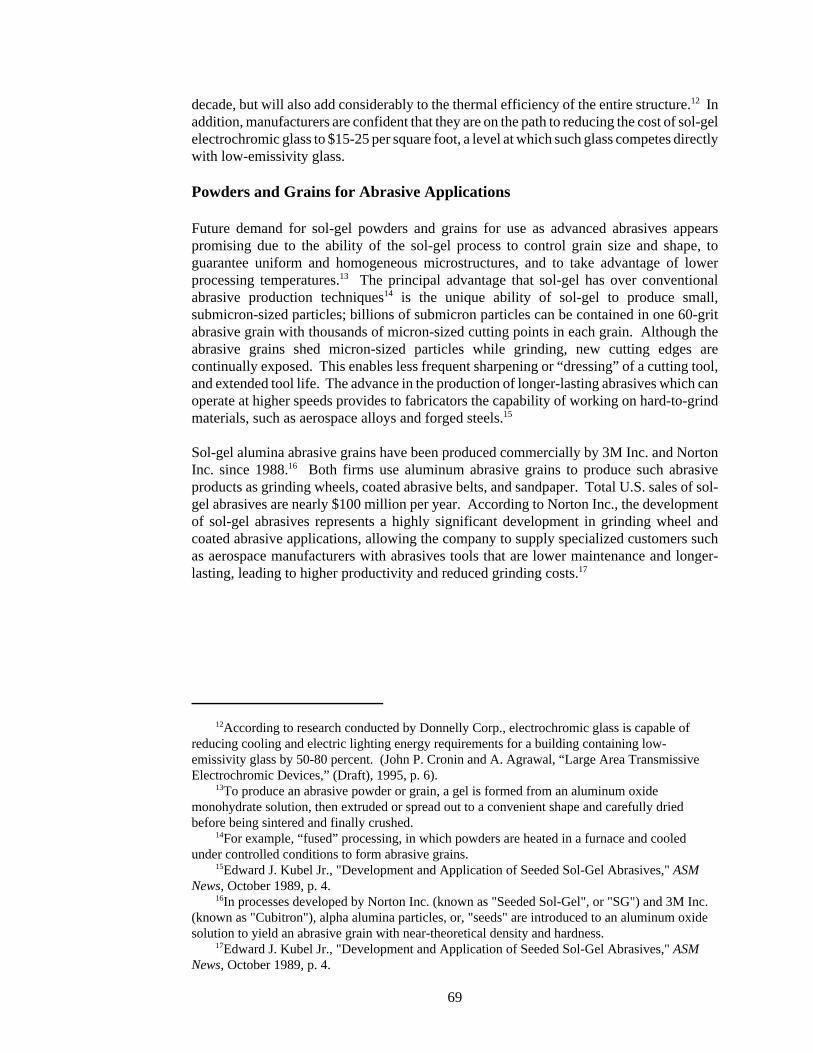
12According to research conducted by Donnelly Corp., electrochromic glass is capable ofreducing cooling and electric lighting energy requirements for a building containing low-emissivity glass by 50-80 percent. (John P. Cronin and A. Agrawal, “Large Area TransmissiveElectrochromic Devices,” (Draft), 1995, p. 6).
13To produce an abrasive powder or grain, a gel is formed from an aluminum oxidemonohydrate solution, then extruded or spread out to a convenient shape and carefully driedbefore being sintered and finally crushed.
14For example, “fused” processing, in which powders are heated in a furnace and cooledunder controlled conditions to form abrasive grains.
15Edward J. Kubel Jr., "Development and Application of Seeded Sol-Gel Abrasives," ASMNews, October 1989, p. 4.
16In processes developed by Norton Inc. (known as "Seeded Sol-Gel", or "SG") and 3M Inc.(known as "Cubitron"), alpha alumina particles, or, "seeds" are introduced to an aluminum oxidesolution to yield an abrasive grain with near-theoretical density and hardness.
17Edward J. Kubel Jr., "Development and Application of Seeded Sol-Gel Abrasives," ASMNews, October 1989, p. 4.
69
decade, but will also add considerably to the thermal efficiency of the entire structure.12 Inaddition, manufacturers are confident that they are on the path to reducing the cost of sol-gelelectrochromic glass to $15-25 per square foot, a level at which such glass competes directlywith low-emissivity glass.
Powders and Grains for Abrasive Applications
Future demand for sol-gel powders and grains for use as advanced abrasives appearspromising due to the ability of the sol-gel process to control grain size and shape, toguarantee uniform and homogeneous microstructures, and to take advantage of lowerprocessing temperatures.13 The principal advantage that sol-gel has over conventionalabrasive production techniques14 is the unique ability of sol-gel to produce small,submicron-sized particles; billions of submicron particles can be contained in one 60-gritabrasive grain with thousands of micron-sized cutting points in each grain. Although theabrasive grains shed micron-sized particles while grinding, new cutting edges arecontinually exposed. This enables less frequent sharpening or “dressing” of a cutting tool,and extended tool life. The advance in the production of longer-lasting abrasives which canoperate at higher speeds provides to fabricators the capability of working on hard-to-grindmaterials, such as aerospace alloys and forged steels.15
Sol-gel alumina abrasive grains have been produced commercially by 3M Inc. and NortonInc. since 1988.16 Both firms use aluminum abrasive grains to produce such abrasiveproducts as grinding wheels, coated abrasive belts, and sandpaper. Total U.S. sales of sol-gel abrasives are nearly $100 million per year. According to Norton Inc., the developmentof sol-gel abrasives represents a highly significant development in grinding wheel andcoated abrasive applications, allowing the company to supply specialized customers suchas aerospace manufacturers with abrasives tools that are lower maintenance and longer-lasting, leading to higher productivity and reduced grinding costs.17

18Fibers are typically either drawn from solution or extruded from monolithic shapes that havebeen dried and sintered.
19For example, fibers for reinforcement of concrete and glass that contain more than 20percent zirconia oxide are difficult to prepare conventionally because of high meltingtemperatures required. (C. Jeffrey Brinker and George W. Scherer, Sol-Gel Science: The Physicsand Chemistry of Sol-Gel Processing, 1990, p. 862)
20John Mack, “Advanced Ceramics Processing; Cracking the Problem,” Materials Edge,July/August 1990, p. 29.
21Porous gels are distinguished from membranes by pore size. The most common form ofporous gels and membranes are aerogels, which are lightweight, nearly transparent, porousmaterials in which the particles and the pores between them have dimensions of less than 100billionths of a meter.
22C. Jeffrey Brinker and George W. Scherer, Sol-Gel Science: The Physics and Chemistry ofSol-Gel Processing, 1990, p. 868.
70
Fibers for Heat-resistant and Reinforcement Applications
Sol-gel processes can be used to prepare continuous, refractory, polycrystalline fibers18 thatdisplay high strength, thermal resistance, stiffness, and durability. The advantage of the sol-gel process in forming fibers is that highly refractory and chemically durable fibers can beeconomically formed at room temperatures; these fibers are difficult to prepare usingconventional high temperature processes.19
Sol-gel fibers are finding commercial use in the aerospace, industrial textile, and electricalindustries because of their purity and their ability to resist heat and corrosive gases.Reinforcement applications for these fibers include use in fabric, tape, and cordage.Refractory textile applications include use in furnace belts, flame curtains, and high-temperature gaskets and cables. Continuous ceramic fibers can also be combined with otherfibers, whiskers, or powders and formed into porous shapes for use as insulation in theaerospace/defense industries (including use as insulating tiles in the U.S. Space Shuttleprogram).20
3M Inc., the only known U.S. manufacturer of sol-gel fibers, currently produces small,commercial quantities of continuous filament ceramic fibers (NextelTM) for use in fabrics,tapes, sleevings and cordage. According to 3M, the high-temperature performance(including low shrinkage, abrasion resistance, and thermo-electric insulation properties) ofNextel 312 and 440 ceramic fibers is superior to inorganic fibers such as fiberglass, or fusedor leached silica. Because of their ability to withstand high temperatures, Nextel fibers arealso being considered for use in matrix-composite materials and in heat exchangers andradiant gas burner tubes in power-generating plants.
Porous Gels and Membranes for Insulation and Filtration Applications21
Porous gels and membranes are characterized by high surface area and small pore volume,making them ideal for applications in thermal and acoustical insulation, in filtration andseparation systems, and in catalytic applications.22 These materials are often difficult toproduce using traditional ceramic processing methods. Sol-gel pore films and membranesoffer a number of advantages over conventional materials:
! they can be used at high temperatures
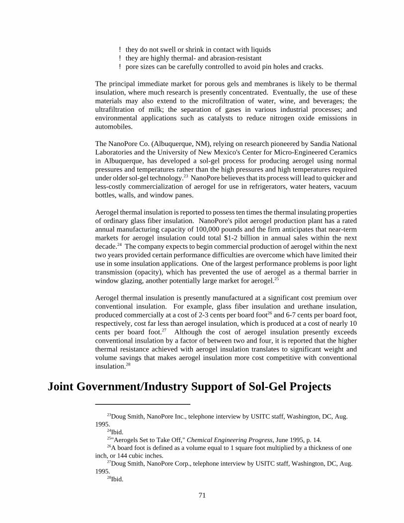
23Doug Smith, NanoPore Inc., telephone interview by USITC staff, Washington, DC, Aug.1995.
24Ibid.25"Aerogels Set to Take Off," Chemical Engineering Progress, June 1995, p. 14.26A board foot is defined as a volume equal to 1 square foot multiplied by a thickness of one
inch, or 144 cubic inches.27Doug Smith, NanoPore Corp., telephone interview by USITC staff, Washington, DC, Aug.
1995.28Ibid.
71
! they do not swell or shrink in contact with liquids! they are highly thermal- and abrasion-resistant! pore sizes can be carefully controlled to avoid pin holes and cracks.
The principal immediate market for porous gels and membranes is likely to be thermalinsulation, where much research is presently concentrated. Eventually, the use of thesematerials may also extend to the microfiltration of water, wine, and beverages; theultrafiltration of milk; the separation of gases in various industrial processes; andenvironmental applications such as catalysts to reduce nitrogen oxide emissions inautomobiles.
The NanoPore Co. (Albuquerque, NM), relying on research pioneered by Sandia NationalLaboratories and the University of New Mexico's Center for Micro-Engineered Ceramicsin Albuquerque, has developed a sol-gel process for producing aerogel using normalpressures and temperatures rather than the high pressures and high temperatures requiredunder older sol-gel technology.23 NanoPore believes that its process will lead to quicker andless-costly commercialization of aerogel for use in refrigerators, water heaters, vacuumbottles, walls, and window panes.
Aerogel thermal insulation is reported to possess ten times the thermal insulating propertiesof ordinary glass fiber insulation. NanoPore's pilot aerogel production plant has a ratedannual manufacturing capacity of 100,000 pounds and the firm anticipates that near-termmarkets for aerogel insulation could total $1-2 billion in annual sales within the nextdecade.24 The company expects to begin commercial production of aerogel within the nexttwo years provided certain performance difficulties are overcome which have limited theiruse in some insulation applications. One of the largest performance problems is poor lighttransmission (opacity), which has prevented the use of aerogel as a thermal barrier inwindow glazing, another potentially large market for aerogel.25
Aerogel thermal insulation is presently manufactured at a significant cost premium overconventional insulation. For example, glass fiber insulation and urethane insulation,produced commercially at a cost of 2-3 cents per board foot26 and 6-7 cents per board foot,respectively, cost far less than aerogel insulation, which is produced at a cost of nearly 10cents per board foot.27 Although the cost of aerogel insulation presently exceedsconventional insulation by a factor of between two and four, it is reported that the higherthermal resistance achieved with aerogel insulation translates to significant weight andvolume savings that makes aerogel insulation more cost competitive with conventionalinsulation.28
Joint Government/Industry Support of Sol-Gel Projects

29John Van Dine, SAGE Electrochromics Corp., telephone interview by USITC staff,Washington, DC, Aug. 1995.
30Dr. Niall Lynam, Donnelly Corp., telephone interview by USITC staff, Washington, DC,Aug. 1995.
31John Gudas, U.S. Department of Commerce, National Institute of Standards andTechnology (NIST), Aug. 1995.
72
Both the U.S. and foreign governments have joined with private firms to assist in thedevelopment of products made using the sol-gel process. Support by the U.S. Governmentof promising technological projects, which often have difficulty attracting private capital,may have important commercial benefits for industry, contributing toward achieving higherlevels of energy efficiency for the entire economy. The financial and technical assistanceprovided by such partnerships allows smaller firms, which tend to be less well capitalizedthan larger firms, to raise the large sums required to develop these expensive technologies.Access to government resources offers smaller firms a means of leveraging costs, thusneutralizing many of the financial advantages of some larger firms. In some cases,participation in a joint project has allowed participants to share research information and topool scientific talent with Government agencies and with other organizations doing similarresearch, such as national laboratories and universities. Sharing research has resulted incertain technical breakthroughs for some firms that potentially shortens the lead timerequired to bring products to market.29 Finally, industry representatives believe thatcontinued backing by national governments of sol-gel projects lends credibility to thecommercial products developed and serves to remove much of the uncertainty associatedwith adoption of new designs that incorporate these products. This is particularly true ofsol-gel electrochromic coatings for architectural windows where the conservative nature ofarchitects has reportedly proved an obstacle to the broader application of sol-gel productsin construction markets.30
The U.S. Federal Government contributes to sol-gel development by funding variousindustrial efforts to commercially produce components using sol-gel. These efforts aremade through a variety of federal agencies and programs, including the AdvancedTechnology Program (ATP) of the U.S. Department of Commerce’s National Institute ofStandards and Technology (NIST), the U.S. Department of Energy, and the AdvancedResearch Projects Agency (ARPA) of the U.S. Department of Defense (table 2). Barringan immediate termination of funding, the present period of anticipated reductions in federalexpenditures for research and development projects is not expected to affect the funding ofprojects already underway. However, because these anticipated reductions will affect thefunding of projects in the future, some agency officials feel they may dampen theenthusiasm of many in industry to present project proposals.31
Although detailed specific information on sol-gel related research and development fundingby foreign private firms and governments is often not available, it appears that there hasbeen a major commitment by leading industrial nations to develop advanced materialstechnology as a means of stimulating economic growth and competitiveness. Financing ofsol-gel research and development in Europe is being done through private and public

32In 1994, the total ministry budget was DM 450 million.
73
Table 2Some current sol-gel related projects financed partially with Federal funds: Participants, U.S. governmentagency, product, and end-use
Participants U.S. government agency Product End-use
Geltech Inc. Department of Commerce Silica glass Optical components (NIST)
SAGE/3M/Rutgers Department of Commerce Electrochromic Architectural (NIST) glass glass
3M Department of Defense Fiber Aerospace and (ARPA) other structural
applications
Aerojet/ Department of Energy Aerogel Thermal and Livermore acoustical National Labs/ insulation Lawrence products Berkeley National Labs
Donnelly Corp. Department of Energy Electrochromic Architectural and Glass automotive glass
institutions (both individual EU governments and through EU agencies). In Japan, therealso appears to be considerable government involvement in sol-gel research anddevelopment. Support by the Japanese Government for sol-gel technology is channeledthrough its Ministry of International Trade and Industry (MITI) and is included with othertechnology assistance in a number of specific materials research projects. Such projectsinclude: High-Performance Ceramics; High-Performance Materials for SevereEnvironments; Advanced Material and Machining System; and Advanced ChemicalProcessing Technology. Germany provides support for sol-gel projects principally throughthe Federal Research Ministry (BMFT),32 which supports activities dedicated to thefollowing sectors: Physical and Chemical Technologies; Ceramics and Glass; andComposite Systems.
Domestic Sol-Gel Activity
Following is a discussion of some projects financed, in part, by the U.S. Government. Manyof these projects are still in the prototype stage but all are expected to result in commercialproduction within 3-5 years.

33Jean-Luc Nogues, R. Layne Howell, “Fabrication of Pure Silica Micro-Optics by Sol-GelProcessing,” July 1992, pp. 1-6.
34Jean-Luc Nogues, Geltech Inc., telephone interview by USITC staff, Washington, DC, Aug.1995.
35Ibid. 36William Moreshead, Geltech Inc., telephone interview by USITC staff, Washington, DC,
Aug. 1995. 37John Van Dine, SAGE Electrochromic Corp., telephone interview by USITC staff,
Washington, DC, Aug. 1995.
74
U.S. Department of Commerce (Advanced Technology Program--ATP)
Geltech Inc. (Alachua, FL) received a $1.3 million grant under the ATP in 1994 to furtherdevelop its patented sol-gel process for the molding of high-purity silica glass for monolithicmicro-optical components to be used as lenses, diffractive and refractive optical devices, anddiffractive gratings. These high-quality silica glass products are reported to have excellentbroadband (ultraviolet to near-infrared) light transmitting properties33 enabling their use inelectronic sensors and in laser systems where they are used as diffractive gratings and micro-lens arrays to split incoming laser beam energy into many equal intensity beams.Traditional molding and finishing techniques often cannot be used to process silica glass forsuch high-performance optical applications because the high temperatures required in usingthese techniques are cost-prohibitive. Moreover, conventional grinding and polishingprocesses are limited in their ability to manufacture small and complex micro-opticalcomponents.34 Geltech hopes to use its sol-gel process to cast net-shape silica glass micro-optical components at room temperature, resulting in products that are extremely pure andhomogeneous, and are also lower in cost than products produced using conventionaltechniques. Thus far, Geltech has been manufacturing dense silica glass for optical productsusing sol-gel technology on a prototype basis, and expects to shortly begin commercialproduction.35 Geltech has also begun commercial production of porous glass for electronicsensor applications as a direct result of its sol-gel work under the ATP grant.36
SAGE Electrochromics, Inc., in cooperation with 3M Inc. and the Rutgers University Centerfor Ceramic Research, was awarded an ATP grant of nearly $3.5 million in 1992 to facilitatethe manufacture of electrochromic glass for use primarily in architectural windows(SAGEGLASSTM). In this process, sol-gel technology is used to deposit several layers ofthin films on a transparent glass base. The momentary flow of electric current to the glassbase then alters the transparency of the glass from clear to heavily shaded. The largestpotential application is in "smart windows," electronically controlled windows thatconserve energy by automatically lightening or darkening, depending on the amount ofsunlight, the time of day, the season, or the preference of the user. The amount of incomingsunlight could be regulated through simple operation of a switch or a remote control to allowbuildings to be shaded on warm days and opened to sunlight on cloudy or winter days.Success in this application could eventually allow the process to be used to produce similarelectrochromic coatings in sensors, superconductors, and optoelectronic circuits. SAGE ispresently producing demonstration prototypes of its electrochromic glazing product andanticipates commercial production by 1997.37
U.S. Department of Energy

38Dr. Niall Lynam, Donnelly Corp., telephone interview by USITC staff, Washington, DC,July 1995.
39Eugenie Uhlmann, Donnelly Corp., telephone interview by USITC staff, Washington, DC,July 1995.
40Dr. Niall Lynam, Donnelly Corp., telephone interview by USITC staff, Washington, DC,July 1995.
41John P. Cronin and A. Agrawal, “Large Area Transmissive Electrochromic Devices,”(Draft), 1995, p. 1.
42Anoop Agrawal, Donnelly Corp., telephone interview by USITC staff, Washington, DC,Sept. 1995.
43"Aerogels Set to Take Off", Chemical Engineering Progress, June 1995, p. 16.
75
Donnelly Corp. is currently in the first year of a three-year, $800,000 joint project with theU.S. Department of Energy to produce electrochromic glass for the architectural andautomotive industries using the sol-gel process.38 Donnelly anticipates that commercialproduction of its electrochromic glass will begin in the third year of this project.39 The firmanticipates some resistance to its product in the marketplace due to its higher initial cost andthe reluctance of some architects to depart from the practice of specifying familiar buildingmaterials with well-established properties. Similarly, automotive designers are alsoreluctant to introduce new design concepts to replace materials with proven acceptance inthe marketplace. However, Donnelly Corp. is confident that once the advantages ofelectrochromic glass are demonstrated and the cost is reduced to more competitive levels,it will be able to effectively compete in these huge markets.40 According to the company,the expected sales of electrochromic glass could exceed $1 billion within the next 5 to 10years.41
Donnelly is confident that it will eventually lower the cost of its electrochromic glass fromthe present $30-35 per square foot to $15-25 per square foot as it continues to maketechnical innovations in product technology. At this lower cost level, electrochromic glasswould begin to compete effectively with conventional low-emissivity glass produced at $10-12 per square foot. Donnelly is now focusing its research efforts on finding cost-effectivemeans to produce electrochromic coatings.42
Aerojet Corp. (Sacramento, CA) has begun production and testing of organic aerogels aspart of a 15-month, $2.6 million Cooperative Research and Development Agreement withLawrence Livermore and Lawrence Berkeley National Laboratories. Commercialmanufacture of these aerogels is expected to begin following the expiration of theagreement in 1996. Potential aerogel identified by Aerojet include refrigeration systems,automotive door panels, ceilings, catalytic converters, and a number of aerospaceapplications.43
U.S. Department of Defense (Advanced Research Projects Agency--ARPA)
3M Inc. is currently working with ARPA to develop Nextel 610, a new generation 99.5percent aluminum oxide fiber to improve the strength and thickness of reinforced metal-matrix and ceramic-matrix composites. Thus far, 3M has supplied a limited quantity ofNextel 610 fibers from its pilot plant to ceramic composite manufacturers for experimentaluse in aircraft engines. 3M also anticipates selling Nextel 610 fibers to reinforce metalssuch as aluminum or titanium for use in aerospace applications such as missile fins, and forstrong, lightweight parts for aircraft, bicycle frames, or automobiles. The company
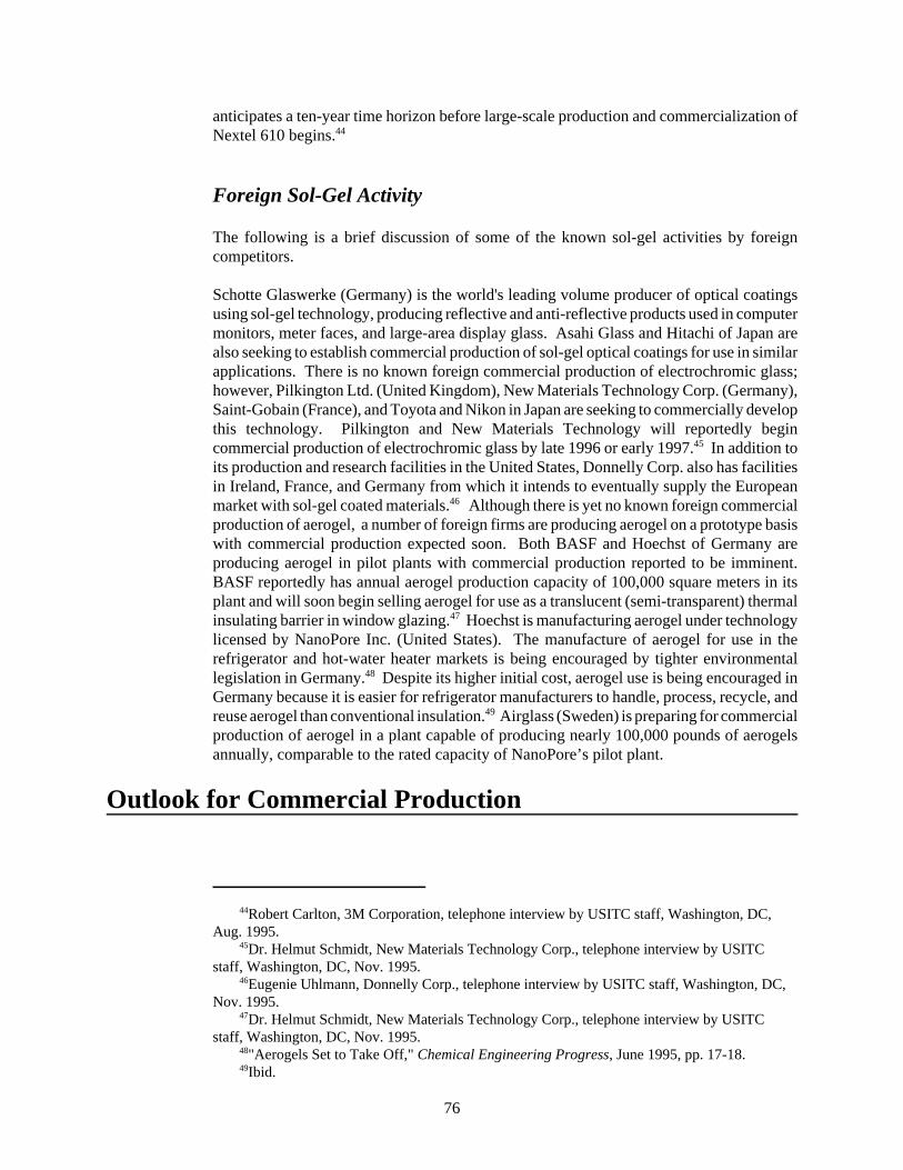
44Robert Carlton, 3M Corporation, telephone interview by USITC staff, Washington, DC,Aug. 1995.
45Dr. Helmut Schmidt, New Materials Technology Corp., telephone interview by USITCstaff, Washington, DC, Nov. 1995.
46Eugenie Uhlmann, Donnelly Corp., telephone interview by USITC staff, Washington, DC,Nov. 1995.
47Dr. Helmut Schmidt, New Materials Technology Corp., telephone interview by USITCstaff, Washington, DC, Nov. 1995.
48"Aerogels Set to Take Off," Chemical Engineering Progress, June 1995, pp. 17-18.49Ibid.
76
anticipates a ten-year time horizon before large-scale production and commercialization ofNextel 610 begins.44
Foreign Sol-Gel Activity
The following is a brief discussion of some of the known sol-gel activities by foreigncompetitors.
Schotte Glaswerke (Germany) is the world's leading volume producer of optical coatingsusing sol-gel technology, producing reflective and anti-reflective products used in computermonitors, meter faces, and large-area display glass. Asahi Glass and Hitachi of Japan arealso seeking to establish commercial production of sol-gel optical coatings for use in similarapplications. There is no known foreign commercial production of electrochromic glass;however, Pilkington Ltd. (United Kingdom), New Materials Technology Corp. (Germany),Saint-Gobain (France), and Toyota and Nikon in Japan are seeking to commercially developthis technology. Pilkington and New Materials Technology will reportedly begincommercial production of electrochromic glass by late 1996 or early 1997.45 In addition toits production and research facilities in the United States, Donnelly Corp. also has facilitiesin Ireland, France, and Germany from which it intends to eventually supply the Europeanmarket with sol-gel coated materials.46 Although there is yet no known foreign commercialproduction of aerogel, a number of foreign firms are producing aerogel on a prototype basiswith commercial production expected soon. Both BASF and Hoechst of Germany areproducing aerogel in pilot plants with commercial production reported to be imminent.BASF reportedly has annual aerogel production capacity of 100,000 square meters in itsplant and will soon begin selling aerogel for use as a translucent (semi-transparent) thermalinsulating barrier in window glazing.47 Hoechst is manufacturing aerogel under technologylicensed by NanoPore Inc. (United States). The manufacture of aerogel for use in therefrigerator and hot-water heater markets is being encouraged by tighter environmentallegislation in Germany.48 Despite its higher initial cost, aerogel use is being encouraged inGermany because it is easier for refrigerator manufacturers to handle, process, recycle, andreuse aerogel than conventional insulation.49 Airglass (Sweden) is preparing for commercialproduction of aerogel in a plant capable of producing nearly 100,000 pounds of aerogelsannually, comparable to the rated capacity of NanoPore’s pilot plant.
Outlook for Commercial Production

50Doug Smith, NanoPore Inc., telephone interview by USITC staff, Washington, DC, Aug.1995.
51John P. Cronin and A. Agrawal, "Large Area Transmissive Electrochromic Devices,"(Draft), 1995, p. 1. This market estimate is based on gaining just a small market penetration of themore than 35 million new cars and trucks produced annually worldwide, and a modest penetrationof the market for low-emissivity windows, which now command 40 percent of the residentialwindow market and nearly 30 percent of the commercial window market.
52Dr. Niall Lynam, Donnelly Corp., telephone interview by USITC staff, Washington, DC,July 1995.
53Doug Smith, NanoPore Inc., telephone interview by USITC staff, Washington, DC, Aug.1995.
77
The principal obstacles to wider use of the sol-gel process in manufacturing are the relatedproblems of cost and performance. Because sol-gel is still a relatively expensive productionprocess, its use presently can only be justified, on a cost basis, for high-performanceapplications which tend to be low-volume. Manufacturers of sol-gel components believethe cost of such components eventually will substantially decline. This is expected to occurthrough a combination of increased demand sufficient to allow average production costs todecline, and further technical breakthroughs aimed at reducing manufacturing costs of sol-gel products to costs of competing products. Another obstacle is the requirement to developmanufacturing processes that guarantee consistent high-volume production of qualitycomponents. Because of existing low production levels for many sol-gel products, processtechnology has not advanced sufficiently to produce components of a consistent level ofquality. Further advances and refinements in processing technology are needed to guaranteeconsistent levels of quality before large production runs can begin.50
Existing large-volume markets which sol-gel manufacturers expect to enter include marketsfor architectural and automotive glass, and for thermal and acoustical insulation. Within thenext 5 to 10 years, the expected sales of electrochromic glass used in architectural andautomotive applications could exceed $1 billion.51 Manufacturers are seeking todemonstrate the ability to produce consistent, high-quality material in the dimensionsrequired for architectural and automotive glass at a competitive cost.52 Entry into thesemarkets would allow manufacturers to produce in sufficient quantities to demonstrateconsistent high quality and also to realize economies of scale, thereby reducing costs further.
Similarly, the market potential for aerogel use in thermal and acoustical insulation is alsopotentially large; estimates of potential U.S. annual sales of aerogel products over the nextdecade approach $2 billion.53 Commercial prospects for aerogel depend on the ability ofmanufacturers to resolve technical problems such as opacity and to reduce costs to levelsthat would make aerogel insulation competitive with conventional insulation. Industryofficials believe that further reductions in the cost of producing aerogel, combined withaerogel's superior thermal qualities, will eventually unlock this large potential market.
Many of the advanced technology markets for sol-gel products do not presently exist involumes large enough to justify increased volume production of sol-gel components.However, this situation is likely to change as such devices as optical lasers, opticalwaveguides, solar cells, and optical fibers find increasing applications in the 21st century.

54William Moreshead, Senior Scientist, Geltech Inc., telephone interview by USITC staff,Washington, DC, Nov. 1997 and product information supplied by Geltech.
55"Low-Cost Method for Aerogels,” R&D Magazine, Sept. 1996, p. 51.56Doug Smith, President, NanoPore Inc., telephone interview by USITC staff, Washington,
DC, Nov. 1997.
78
The U.S. Government has played an important role in facilitating the financial investmentand innovative research efforts required to bring this technology to market and to matchresearch and development efforts of foreign governments. A variety of jointly funded U.S.programs have committed significant resources to developing the commercial viability ofthis technology. Continuation of joint efforts is viewed by some industry officials and end-users as an important component in ensuring the domestic commercial success of thispromising technology, and global competitiveness in this new technology field.
Recent Developments
Although commercial application of sol-gel technology continues to be concentrated in sol-gel abrasives, its use in the manufacture of films, coatings, powders and grains, fibers, andporous gels and membranes for other end-use industries has grown rapidly in recent years.Total U.S. sales of sol-gel produced products rose from less than $200 million in 1995 tonearly $300 million in 1997, of which approximately $200 million is sales of sol-gelabrasives. For nonabrasive end-uses, the use of sol-gel to produce silica glass for opticalproducts was largely being done on a prototype basis in 1995. Today, the sol-gel process isbeing used to commercially produce silica lenses for the electro-optics industry. Althoughthe grant to Geltech Inc. (Orlando, FL) for prototype production of high-purity silica glassfor monolithic micro-optical components under the ATP (Advanced Technology Program)expired in 1997, the sol-gel technology developed through the ATP allowed the firm tobegin commercial production of porous glass for use in electronic sensors designed for homemonitoring systems. The company currently produces more than 100 million units of suchglass annually. Geltech’s development work in sol-gel also was instrumental in the firm’sselection for a U.S. Department of the Army contract for $500,000 to build prototypewindows molded in silica. The windows will be mechanically hard, transparent to visibleand infrared light, resistant to laser radiation, and possess the necessary optical quality formilitary and commercial applications. Eventual applications include night-vision optics,imaging systems for tank periscopes, surveillance camera systems, and power-limitingdevices for commercial systems.54
The manufacture of porous gels and membranes for thermal insulation is still largely in theproduct development stage but is nearing commercial availability. Some joint commercialproduction of aerogel by Allied Signal Corp. and the NanoPore Corp. (Albuquerque, NM)is used by the semiconductor industry. NanoPore, in combination with Sandia NationalLaboratories, the University of New Mexico, and the U.S. Department of Energy has alsodeveloped a sol-gel process for producing aerogels which has reduced product cost from ashigh as $45/kg to as low as $7/kg, a price at which it begins to compete with conventionalglass-fiber insulation.55 NanoPore is currently producing aerogel at its pilot plant in Illinoisand soon expects to begin commercial production of more than a million pounds of aerogelannually, dedicated largely for the building construction market.56 According to NanoPoreofficials, aerogel thermal insulation possesses 10 times the thermal insulating properties of

57Ibid.58Officials of Donnelly Corp., telephone interview by USITC staff, Washington, DC, Nov.
1997.
79
ordinary glass fiber insulation; the total market for aerogel insulation could reach $1 to 2billion by 2005.57
The market for sol-gel coatings for use in electrochromic glass used in the manufacture of“smart windows”, continues to advance. Donnelly Corp. (Holland, MI), a commercialproducer of sol-gel optical barrier coatings for electrochromic displays, has been involvedin a project, financed partly by the U.S. Department of Energy, to produce optical glasscoatings using sol-gel processing for the architectural market. As a result of technologydeveloped during this project, Donnelly has decided to build a pilot plant to produce 5,000to 10,000 square feet of electrochromic glass in 1998. The cost of the glass produced islikely to be in the range of $30 to $35/square foot, compared with conventional low-emissivity glass, which is produced at $10 to $12/square foot. Donnelly remains confidentthat as production is scaled up, average cost will fall to $15 to $25 per square foot, a levelat which such glass competes directly with conventional low-emissivity glass. Annualmarket potential for electrochromic coatings has been estimated at $1 to $2 billion by2005.58

80
Glossary of Terms
Aerogel The most common form of porous gels and membranes, whichare lightweight, nearly transparent, porous materials in which theparticles and the pores between them have dimensions of lessthan 100 billionths of a meter.
Arrays An arrangement of micro-lenses of equal diameter and curvaturewhich are assembled into compact units. Micro-lens arrays aretypically used in semiconductor laser devices.
Colloid A state in which small particles of solid, liquid, or gas aredistributed in a gas, liquid or solid. The dispersed particles areso small that they do not form an obviously separate phase, butthey are not so small that they can be said to be in true solution.
Diffractive grating An optical device, used in laser systems, to produce discretebeams of energy by diffracting various incoming wavelengths ofelectromagnetic energy.
Electrochromic glass Glass or layers of glass upon which several layers of thin,transparent, and conductive coatings of materials such astungsten oxide are deposited. By varying the amount ofelectrical energy supplied to the glass, the transparency of thecoatings can be altered to vary the amount of light or heatpenetrating the glass.
Gel A colloid in which a liquid contains a solid arranged in a finenetwork extending throughout the system to produce a viscous,jelly-like product.
Low-Emissivity A surface coating for glass that permits the passage of mostshortwave electromagnetic radiation (especially light), butreflects most longer-wave radiation (heat).
Matrix-composites Advanced materials in which discrete or continuous reinforcingfibers are embedded in a matrix, often of metal or ceramic.Composites have very high strength and stiffness in the directionof the fibers.
Monoliths Bulk gels that are cast to complex shapes. Monolithic gels areoften formed at room temperature and consolidated into finalshapes at lower temperatures.
Nanometer A unit measuring thickness in billionths of a meter.
Net-shape A processing method which is used to produce a semi-manufactured part which is close to the final manufactured part.

81
Eliminates the need for extensive and more costly finishingoperations.
Oxide A binary compound of oxygen with another element. Mostoxides are prepared by reacting an element with oxygen at anappropriate temperature.
Porosity The state of a material which allows the passage of gas or liquidthrough pores in the material. Porosity varies with the particlesize of the material.
Precursor An intermediate compound used in the formation of specificfinal materials.
Refraction The change of direction in the propagation of a light wave as itpasses through a medium such as glass.
Sintering The bonding of adjacent surfaces in a mass of particles bymolecular or atomic attraction. Sintered materials are heated attemperatures below the melting temperature of any componentpart in the material.
Sol Sometimes known as a colloidal solution. A liquid colloidaldispersion.
Solution A uniformly dispersed mixture, at the molecular or ionic level,of one or more substances (the solute) in one or more substances(the solvent). These two parts of a solution are called phases.
Stoichiometry The branch of chemistry that deals with the quantities ofsubstances that enter into and are produced by chemicalreactions.
Substrate Any solid surface on which a coating or layer of a material isdeposited.
Vapor Deposition A process used to apply a thin coating with a desired set ofproperties to an inexpensive substrate. The most popular vapordeposition methods used by industry include Chemical Vapor(CVD) and Physical Vapor Deposition (PVD).

83
Direct Ironmaking: A Case Study inGovernment and Industry Cooperation toCommercialize Manufacturing Processes forMaterialsCheryl Badra Qassis(202) [email protected]
This article examines a U.S. government-industry project todevelop and commercialize direct ironmaking. This processeliminates the traditional and increasingly expensive cokeprocessing element of steelmaking, which is considered importantto improving the competitiveness of the U.S. steel industry. Thisarticle explores key factors affecting commercialization of directironmaking, the role of industry and government institutionsinvolved in its research and development, the status of competingprocesses abroad, and the result of the joint project.
Since this article was first published in the Industry, Trade, andTechnology Review of May 1995, the joint U.S.industry-Government effort to develop an alternative ironmakingprocess was concluded, but additional commercialization fundinghas not been provided. However, several other technologiesdeveloped abroad have moved closer to commercialization.Beyond the already widely used Corex process, it appears that theRussian Romelt process will be the next smelting process to becommercialized. Competing with the smelting technologies areseveral other processes that use the direct reduction method toproduce direct reduced iron (DRI). Midrex and Hylsa are alreadywidely used; several others are near commercialization. Givenbudgetary constraints, it is unlikely that the U.S. Government willfund further work in developing an alternative ironmaking process.The concluding section of this article elaborates on recentdevelopments.
Note: A glossary of technical terms and abbreviations(highlighted within the article by bold italics) appears at theend of this article.
Increasing competition abroad and rising costs at home have spurred efforts by the U.S. steelindustry to develop and commercialize new technologies that will increase efficiency andproductivity, lower production costs, and improve material characteristics. A recentlyconcluded 5-year pilot project funded by the U.S. Department of Energy (DOE) and theAmerican Iron and Steel Institute (AISI) explored the technical and economic viability of

1The phrase "direct steelmaking" is often used interchangeably with the term "directironmaking." Because products resulting from this process are expected to be high carbon iron,not steel, this article will refer to the process as "direct ironmaking."
2In bath smelting, oxygen, prereduced iron ore pellets, coal and flux are charged into amolten slag bath containing a high percentage of carbon. Slag is an accumulation of theimpurities released from the ore that collect on the surface of the bath during smelting. Thecarbon removes oxygen from the iron ore and generates carbon monoxide and liquid iron. Oxygen is then injected to burn some of the carbon monoxide gas before it leaves the smeltingvessel (post combustion). The heat from the burning gas then generates a portion of the energyused in the reduction of the ore in the bath. The partially combusted gas is used to preheat andprereduce the ore, which means removing a portion of the oxygen content before the ore isinjected into the bath. American Iron and Steel Institute, Direct Steelmaking Program, AISI, p. 4.
3Paul Millbank. "Direct Route To Iron Gathers Momentum," Metal Bulletin MonthlySupplement, Apr. 1995, p. 24.
4The 1990 amendments to the Clean Air Act tightened regulations on coke oven emissions.
84
direct ironmaking,1 pursuing a process based on bath smelting.2 The consensus of thedomestic and international steel industry is that bath smelting is the prime technology of thefuture of high quality iron production for steelmaking.3 The joint project to develop directironmaking in the United States is one of several efforts underway worldwide to incorporatethe smelting technology into the steelmaking process.
The purpose of the AISI-DOE direct ironmaking project was to develop a cost-effective,efficient, and environmentally safe technology that will reduce costs and, in the long run,increase the productivity of steel producers. For the integrated steelmaker, the blast furnaceis the primary vehicle for producing molten iron, of which coke is a major input. Asmetallurgical coal reserves in the United States declined and the costs associated withcokemaking rose, steelmakers began to pursue the direct use of coal in ironmaking,including pulverized coal injection (PCI) in blast furnaces. These methods can partiallyreduce the amount of metallurgical coke needed to produce iron (known as the coke rate),whereas cokeless bath smelting technology would replace coke altogether.
There are several reasons the direct ironmaking project was initiated. The American steelindustry is facing potential capital investment costs, running into billions of dollars, as alarge portion of its cokemaking capacity nears the end of its design life. Increasinglystringent environmental regulations4 have raised both the capital and operating costs of cokeoven batteries, generating the need to explore technologies that would eliminate this stepfrom the integrated steelmaking process. A description of the past, current, and anticipatedfuture processing methods of steelmaking are outlined in figure 1.
Foreign steel industries, facing similar challenges, have also pursued research in the area ofdirect ironmaking technology, and two have been identified as front-runners in the race tocommercialize the technology: Corex, which has already been commercialized by Austria'sVoest-Alpine Industrieanlagenbau (VAI), and DIOS of Japan. The status of thesetechnologies is discussed later.
The challenge for these new processes, however, is that adoption by the industry dependsnot only on the technical proficiency of the new technology, but also on proven, significantpotential for economic advantage over the traditional coke oven or blast furnace method.


86
85

5The Metals Initiative Program of 1988, which was established by the Steel and AluminumEnergy Conservation and Technology Competitiveness Act of 1988, augments the Steel Initiativeby expanding its mandate to encompass a wider variety of metals. Its purpose is twofold: (1) to"increase the energy efficiency and enhance the competitiveness of American steel, aluminum andcopper industries...; and (2) to continue steel research and development efforts begun under theDepartment of Energy (DOE) program known as the Steel Initiative." Steel and AluminumEnergy Conservation and Technology Competitiveness Act of 1988 Annual Report (Washington,DC: U.S. Department of Energy, Feb. 1990).
6Egil Aukrust, AISI Direct Steelmaking Program Final Technical Report, U.S. Department ofCommerce, Technology Administration, National Technical Information Service, Springfield,VA, Aug. 1994, p. 2.
7J.M. Farley and P.J. Koros, AISI-DOE Direct Steelmaking Program, AISI, Jan. 30, 1992, p.1.
8There is a large, modern installed capacity for production and transport of pellets in NorthAmerica. According to statistics compiled by Skillings Mining Review (July 30, 1994), total U.S.and Canadian iron ore pellet plant production in 1993 was 73.7 million metric tons, with anestimated 9 percent increase in 1994 to 80.3 million metric tons. Total annual capacity is 87.1million metric tons.
87
Confirming that these two criteria were achievable through the direct ironmaking processwas the goal of the AISI-DOE pilot project.
DOE's involvement in this project was made possible through legislation known as the SteelInitiative of 1986.5 This legislation was a result of proposals by the President's Council onIndustrial Competitiveness to support joint research efforts by the industry and nationallaboratories. The substance of the bill was developed by a DOE-AISI joint task force, andmandates that costs of research and development of new technology be shared towardachieving the purpose of saving energy, increasing competitiveness, and generating benefitsfor the entire industry.
The DOE-AISI collaboration is an example of government involvement to enhance thecompetitiveness of U.S. industries through cooperative technology development. The effortto develop the direct ironmaking process for commercial use demonstrates a convergenceof interests, and is unique in light of multiple company-industry-government cooperationand the role of environmental regulation driving new process adoption. The mixed resultsof the joint AISI-DOE direct ironmaking program may have implications for futuregovernment-industry cooperative initiatives.
DOE-AISI Pilot Project Background
In 1987, AISI assembled a task force to select the process most likely to improvecompetitiveness of the U.S. steel industry and to outline a program of research anddevelopment to facilitate rapid implementation of the technology. After an extensive reviewof cokeless iron and steelmaking technologies that were already under developmentworldwide, the task force concluded that future steelmaking should be based on acoke-free, coal-based bath smelting process for the production of the hot metal that issubsequently refined to steel.6 However, the task force determined that foreign technologiesunder development did not adequately meet certain requirements of the North Americansteel producer,7 including a coal-based operation that utilized pelletized iron ore feed,8 aprocess that maintained the flexibility to melt scrap as well as the ability to generate excessenergy for other uses, and a process that resulted in substantial reductions in capital and

9Research related to the program was conducted at Carnegie Mellon University (CMU),Massachusetts Institute of Technology (MIT), University of British Columbia (UBC), McGillUniversity (McG), McMaster University (MU), and at the U.S. Steel (USS) and the UnionCarbide Industrial Gases Technical Centers. Farley and Koros, AISI-DOE Direct SteelmakingProgram, pp. 2-3.
10Involved organizations included International Business Machines (IBM), North AmericanRefractories Co. (NARCO), Linde Industrial Gases, EG&G, U.S. Steel, and Dofasco Steel, Inc.,among others.
11Egil Aukrust, AISI, conversation with USITC staff, Mar. 13, 1995.
88
operating costs. As a result, the task force recommended that AISI propose a research anddevelopment program for joint funding by the industry and DOE. Two years of proposaldevelopment and assessment were involved before work on the DOE-AISI program actuallybegan in November 1988. The chronology of project development is outlined in table 1.
Table 1Chronology of project development
Apr. 1987 DOE issues Steel Initiative Management Plan, which provides a framework for implementation ofresearch programs, and follows with a research plan identifying a number of key areas where the steelindustry could benefit from advanced technology, including direct ironmaking.
Aug. 1987 AISI assembles a task force to explore existing domestic and foreign technologies that could befurther developed to enhance the U.S. steel industry's competitiveness.
July 1988 AISI submits a research proposal to the DOE for development of a direct ironmaking process.
Nov. 1988 Work begins on the AISI-DOE direct ironmaking project.
Dec. 1988 On recommendation from the House Committee on Science, Space and Technology, Congress enactsan amendment to the Steel Initiative, which substantially increased funding of the direct ironmakingproject.
May 1989 The AISI-DOE Cooperative Agreement for the direct ironmaking project is approved by the DOE.Source: AISI.
Management and Funding
The projected budget of the joint AISI-DOE project was $30 million for 3 years.Subsequent amendments extended the project to March 31, 1994, a total of 5 1/2 years, witha total cost of $60.3 million. DOE provided $46.3 million (77 percent), while AISI providedthe remaining $13.9 million (23 percent).
Cooperating organizations provided services, personnel, equipment, and technical expertiseto the project. Research encompassed three coordinated efforts: university research9 on pellet-slag-coal reactions; industrial research10 on prereduction, BOF postcombustion, andheat transfer; and research conducted at the pilot plant to experiment at the 15 ton scale withprocess performance. No national laboratories were involved in this project.11
A Technical Advisory Committee consisting of senior professional personnel from the steelindustry was created to oversee technical issues and to provide individual project
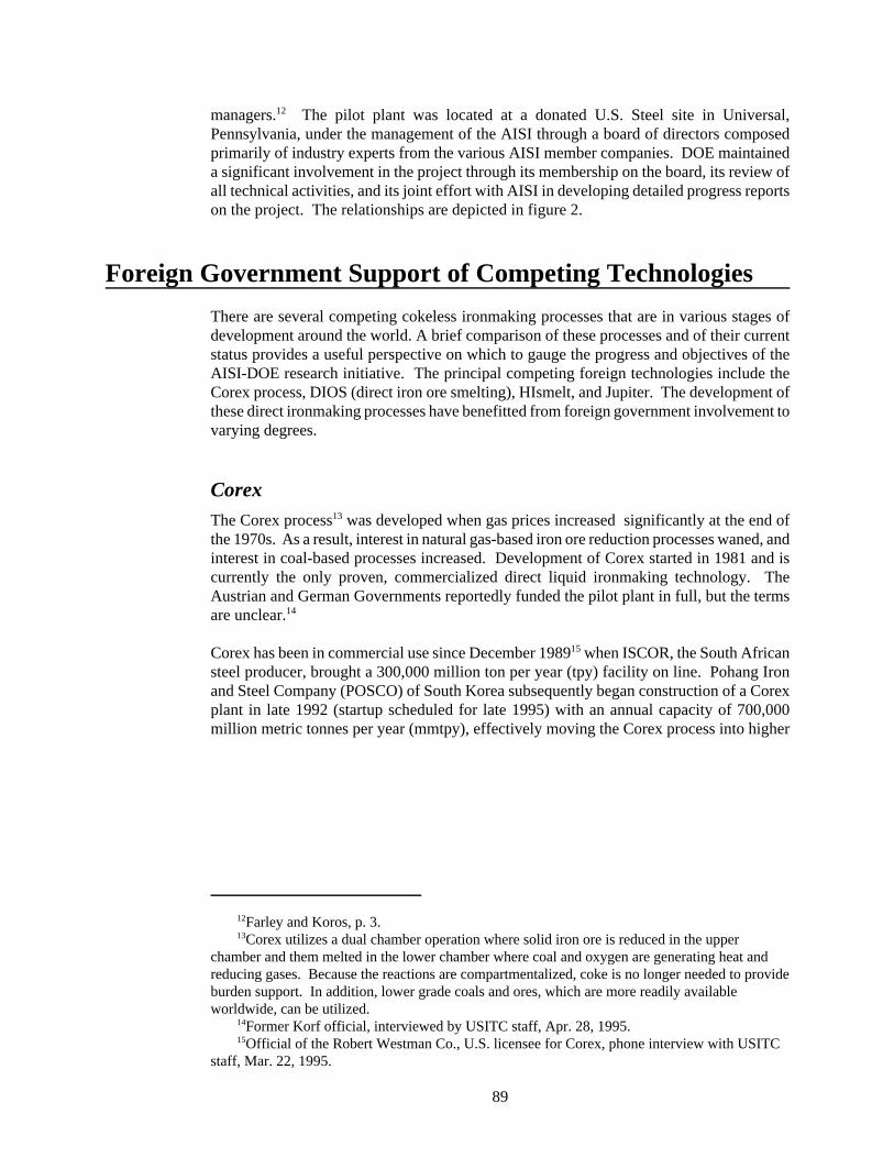
12Farley and Koros, p. 3.13Corex utilizes a dual chamber operation where solid iron ore is reduced in the upper
chamber and them melted in the lower chamber where coal and oxygen are generating heat andreducing gases. Because the reactions are compartmentalized, coke is no longer needed to provideburden support. In addition, lower grade coals and ores, which are more readily availableworldwide, can be utilized.
14Former Korf official, interviewed by USITC staff, Apr. 28, 1995.15Official of the Robert Westman Co., U.S. licensee for Corex, phone interview with USITC
staff, Mar. 22, 1995.
89
managers.12 The pilot plant was located at a donated U.S. Steel site in Universal,Pennsylvania, under the management of the AISI through a board of directors composedprimarily of industry experts from the various AISI member companies. DOE maintaineda significant involvement in the project through its membership on the board, its review ofall technical activities, and its joint effort with AISI in developing detailed progress reportson the project. The relationships are depicted in figure 2.
Foreign Government Support of Competing Technologies
There are several competing cokeless ironmaking processes that are in various stages ofdevelopment around the world. A brief comparison of these processes and of their currentstatus provides a useful perspective on which to gauge the progress and objectives of theAISI-DOE research initiative. The principal competing foreign technologies include theCorex process, DIOS (direct iron ore smelting), HIsmelt, and Jupiter. The development ofthese direct ironmaking processes have benefitted from foreign government involvement tovarying degrees.
CorexThe Corex process13 was developed when gas prices increased significantly at the end ofthe 1970s. As a result, interest in natural gas-based iron ore reduction processes waned, andinterest in coal-based processes increased. Development of Corex started in 1981 and iscurrently the only proven, commercialized direct liquid ironmaking technology. TheAustrian and German Governments reportedly funded the pilot plant in full, but the termsare unclear.14
Corex has been in commercial use since December 198915 when ISCOR, the South Africansteel producer, brought a 300,000 million ton per year (tpy) facility on line. Pohang Ironand Steel Company (POSCO) of South Korea subsequently began construction of a Corexplant in late 1992 (startup scheduled for late 1995) with an annual capacity of 700,000million metric tonnes per year (mmtpy), effectively moving the Corex process into higher

89

16India's Jindal Group placed an order in July 1996 for a 640,000 tpy Corex plant to be builtin Karataka state to serve a new hot rolled steel plant, and a letter of intent has been signed for asecond unit. The first is expected to be in operation by late 1997. A month after the Jindal order,South Korea's Hanbo Steel and General Construction ordered two 750,000 tpy Corex plants;startup is expected in mid-1997.
17"The Impact of Changes in the Iron and Steel Industry on Coal-tar Production from CokeOvens," Steel Times, May 1994, p. 175.
18DOE had originally approved funding to help install a Corex reactor at LTV SteelCompany's Cleveland (OH) Works. However, LTV's plans were tabled in 1994 reportedlybecause earnings projections on electricity were not satisfactory. "Geneva, At Last, May GetCorex," 33 Metalproducing, Nov. 1994, p. 9.
19Dr. Lowell Miller, Associate Deputy Assistant Secretary, Clean Coal Technology Program,phone interview with USITC staff, May 17, 1995.
20The DIOS process uses pressure to retard gas velocity, cut coal consumption, and promotecarbon monoxide combustion. Ore pellets are fed into a fluidized bed reduction furnace at thesame time that coal is injected through the bottom. Partially reduced ore and tar then move into asmelting furnace that is fed coal and oxygen simultaneously.
21"Research On A Next-Generation Ironmaking Process," Steel Today and Tomorrow,July-Sept. 1994, p. 7.
22Representative of the Japan Steel Information Center, interviewed by USITC staff, Mar. 21,1995.
23"Research On A Next-Generation Ironmaking Process," Steel Today and Tomorrow, p. 8.
91
volume iron production. At present, Voest-Alpine has received new orders from Turkey,India, and Korea16 for plants with production capacity up to 600,000 tpy, and there isreported significant interest by the former Communist countries.17
The Corex process in the United States may get financial support from the DOE.Airproducts and Chemicals Inc., Centerior Energy Corp., and Geneva Steel Co. plan tojointly invest money in a Corex ironmaking plant to be built at Geneva's Vineyard, Utahmill, which will produce 3,000-3,200 tons per day (tpd) of hot metal and generate 250megawatts of electricity from byproduct gases. The Department of Energy, through itsClean Coal Technology program, had originally approved partial funding for a Corexinstallation at another steelmaker's facility. The Geneva plan envisions the DOEcontributing $150 million of the project's $825 million total cost. The partners must obtainDOE approval to relocate18 the project to Utah, however, and negotiate the Department'scooperative role. Negotiations, presently underway, are expected to conclude in July, 1995.A 1999 operational start-up date is expected.19
DIOSThe DIOS process20 has been the subject of cooperative research between the Japan Iron andSteel Federation (JISF), Japan's eight integrated steelmakers, and the Center for CoalUtilization in Japan. According to the Japan Iron and Steel Federation, the research projecthas been supported since 1988 with subsidies and aid by the Ministry of International Tradeand Industry (MITI).21 The 7-year project was budgeted at 13 billion yen (approximately$100 million), two-thirds of which was provided by MITI.22 In developing the DIOSprocess, JISF has been holding technology exchange meetings with counterparts of variouscountries in an attempt to foster international cooperation in the technology developmentprocess.23
Operations at the 500 tpd pilot plant at NKK Keihan's works began in December 1993 and

24HIsmelt uses a circulating fluid bed reactor for preheating and prereduction. Hot blast air isused for the initial combustion of the coal because the nitrogen in the air is believed to promoteheat transfer and to control postcombustion temperatures. Smelting begins with the bottominjection of coal which is dissolved in the bath. The dissolved carbon is used to reduce the ironore, releasing carbon monoxide which is post-combusted by injecting oxygen in the bath.
25Official of Midrex Corp., interviewed by USITC staff, Mar. 21, 1995.26The Jupiter process is unique in that coal gasification occurs in the reduction process (the
others are based on the gasification of coal in the smelting reaction and on the direct use of theresulting gas in the reduction, both reactors being physically and metallurgically linked), and,therefore, secures the reducing gas and energy requirements. In this first step, it delivers amixture of directly reduced iron and char, which is used in a melting process using both fossil fuel(residual char) and electric energy. The resulting gas from melting is thus not used for reduction.
27Funds for ECSC research grants are drawn from monies collected from producers via atonnage-based production levy.
92
will run through 1995, at which time a formal assessment will be made by the participatingcompanies as to the success of the project. According to JISF, the DIOS process is expectedto reduce costs by about 10 percent and to cut carbon dioxide emissions 5 to 10 percentcompared with blast furnace ironmaking. Other anticipated benefits include the direct useof nonmetallurgical coal for greater flexibility in selecting resources (Japan has nometallurgical coal reserves) and facility and energy cost reductions because of theelimination of the iron ore sintering and cokemaking processes. Full commercialization ofDIOS is expected by the year 2000.
HIsmeltThe Australian company CRA Ltd. and Midrex Corporation of North Carolina formed a50-50 joint venture in 1989 to develop a direct smelting process, known as HIsmelt.24 These partners have spent approximately $200 million developing the process, including theconstruction of a 150,000 tpy demonstration plant at the HIsmelt Research and Developmentin Kwinana, Western Australia. HIsmelt has been entirely financed by the two partners,without any government support.25 HIsmelt is ideal for Australian steel producers becauseit is suited to Australia's Pilbara iron ores, and for iron production using low-cost iron oresand nonmetallurgical coals.
Jupiter
The European program, Jupiter,26 was the result of an initiative started in 1989 by theFrench steelmaker Usinor-Sacilor looking for a smelting reduction process to supply virginmetal to electric steelmaking plants. The development of the Jupiter concept was supportedby research work by IRSID (Usinor-Sacilor Process Research Center). Jupiter receivedpartial funding from the European Coal and Steel Community (ECSC), a predecessor to theEuropean Union.27 The remainder of the financial support was generated by the threeEuropean companies: Usinor, Lurgi, and Thyssen Stahl. Although demonstration of thefeasibility of the reduction process on a pilot plant scale was under discussion, the Jupiterprogram was apparently abandoned last year.
Research Goals and Results

28AISI, Direct Steelmaking Program, p. 4.29Ibid.30Ibid, p. 2.31International Iron and Steel Institute, Steel Statistical Yearbook 1994, Committee on
Statistics, Brussels, 1994, pp. 12-13.32American Iron and Steel Institute, "AISI Direct Steelmaking Findings Encouraging, Lead to
New Research on Waste Oxide Recycling," press release, AISI, Washington, DC, May 18, 1994,p. 1.
33The nozzles through which the hot blast of air is directed into the smelting vessel.34Aukrust, AISI Direct Steelmaking Program Final Technical Report, p. 8.
93
AISI directed its research efforts in the direct ironmaking project to address perceiveddeficiencies in the other technologies being developed abroad. For example, the AISI taskforce had determined that the most advanced process, Corex, which was operating on ademonstration basis in South Africa at the time, was inadequate since it did not employ thepost-combustion process needed to ensure thermal balance. In addition, the economicviability of the Corex process, largely based on the significant byproduct production oflow-BTU gas, was questioned by the task force.28
The AISI-DOE project sought to develop optimum designs and operating techniques for thesmelter and associated equipment as well as to solve engineering problems involved inmaking the process work economically on a commercial scale.29 AISI initially expected thatits process would have reduced direct operating costs by $10 to $25 per ton of steelproduced, compared to the present coke oven-blast furnace-basic oxygen furnace (BOF)technology. The energy cost savings are estimated at about 20 percent.30
In addition, AISI believed that its research had potential for application by minimill (non-integrated) producers using the electric arc furnace (EAF), which account for almost 40percent of the steel produced in the United States today and 31 percent of steel producedworldwide.31 AISI's direct ironmaking process was intended to enable the iron to be castinto "pigs" that could compete economically as input in EAF production with high-qualityscrap, which is becoming more scarce worldwide.
The joint AISI-DOE direct ironmaking project ended in March, 1994, revealing a gapbetween the actual results obtained at the pilot plant and the established goals forproductivity and fuel rate. This gap, which affects both capital and operating costs, isestimated to be approximately 40 percent in the case of high volatile coals. Nevertheless,AISI expressed optimism that the gap can be closed by addressing the deficient aspects ofthe process.32 These include improved distribution of oxygen through the application ofside-blown tuyeres,33 better distribution of raw materials in the reaction vessel, the use ofnewly developed sensors to measure foam height and to observe char distribution andbehavior within the pressurized vessel, and cooperative information exchanges with othersmelting programs.
According to AISI's final technical report, the pilot plant project indicates that the processfundamentals, on which the joint program was initiated, are valid. Further, it notes thatdespite the shortfalls, several steel companies view the results to be sufficiently encouragingto consider building a demonstration plant.34 Comparative savings in the capital andoperating costs for the coke oven-blast furnace and AISI processes of ironmaking are

35Ibid, p. 1.36The estimated costs include stirring the bath with nitrogen. It is expected that nitrogen will
eventually be replaced with air, at a savings of $1.40 per metric ton. Other items, including betterhot metal desulfurization and the substitution of fluxes, could result in additional savings,according to AISI.
94
projected to be in excess of ten percent.35 A cost comparison is reflected in table 2.
Table 2Projected cost advantages of AISI's direct ironmaking process v. existing coke oven/blastfurnace1
Coke oven/ AISIBasis blast furnace process
Dollars per annual metric ton
Capitalcosts . . . . . . . . . . . . . . . 243 160
Metric tons per day per cubic meter
Production intensity . . . . . . . . . . . . 1.0 4.6
Dollars per metric ton
Operating costs . . . . . . . . . . . . . . . 131 120 1 Costs are per annual metric ton of hot metal based on plants with hot metal capacity of one million metrictons per year.
Source: Aukrust, AISI Direct Steelmaking Program, pp. 139-40.
The reported significant cost advantage of the AISI process derives in part from its muchgreater process intensity. These data reflect the much smaller size of the AISI smeltercompared with other units of similar production capacity, which substantially reducesconstruction costs. Finally, with regard to the variable operating cost estimates for the twoprocesses, certain cost factors could further decrease the AISI cost by up to $5 per metricton through scaleup or maturation.36
Based on the findings of the direct ironmaking pilot project, AISI and DOE launchedanother cooperative pilot project, the Steel Plant Waste Oxide Recycling and ResourceRecovery by Smelting Program in April, 1994, to determine the feasibility of convertingsteel plant waste to pig iron for use in steelmaking or foundry industries. According to AISI,the steel industry currently generates three million tons of blast furnace and basic oxygenfurnace dusts and one half-million tons of rolling mill sludge each year. The Waste Oxideproject is aimed at recovering these wastes, most of which are currently disposed of inlandfills, a process that is growing increasingly expensive. Further, it is estimated that

37American Iron and Steel Institute, "Waste Oxide Recycling Demonstration Weighed as PilotProject Successfully Concluded," press release, Jan. 30, 1995.
38Like the direct ironmaking project, the DOE's contribution of the waste oxide project isfunded by the Metals Initiative.
39They include Acme Metals, Cleveland-Cliffs, Geneva Steel, Georgetown Industries,HARSCO, Inland Steel, LTV Steel, Lukens, National Steel, Rouge Steel, Stelco, USS Kobe, andUSX. Additional financial assistance will be provided by principal subcontractors and suppliers,including Mannesmann Demag, Hatch Associates, and NARCO Research.
40The feasibility study will quantify the potential economic return on a smelter at the LakeErie Works plant of Stelco and should provide the information necessary for proceeding with aproposal for a demonstration plant by the spring of 1995, according to AISI. The smelter wouldbe designed to process about 600,000 tpy of waste oxides and to produce about 250,000 tons ofhot metal per year.
41Researchers have learned how to optimize the direct ironmaking process by understandingbetter such issues as the dissolution of materials, reduction mechanisms and rates, slag foamingand control, the behavior of sulfur, dust generation, and the entire question of energyefficiency--including postcombustion and the role of coal volatile matter.
42Aukrust, AISI Direct Steelmaking Program Final Technical Report, p. 9.
95
widespread recycling of steel plant wastes could save 10 trillion BTU of energy per year.37
The Waste Oxide project further broadens and enhances the basic smelting technologydeveloped by the direct ironmaking project. It is directed by the same AISI team and usesthe same pilot plant built for the direct iron smelting project. DOE is providing 70 percentof the project's $7 million cost,38 and AISI members are responsible for the remaining 30percent. AISI's portion is funded on an elective basis by 13 of its member companies.39
In January, 1995, AISI announced that the waste oxide pilot project had been successfullycompleted, laying the groundwork for a possible commercial demonstration project. Projectdirectors determined in December that no further trials were required, ending the project 2months ahead of schedule. The engineering firm of Mannesman DeMag was commissionedto work with AISI on conducting a feasibility study of the economic returns of a full-scaledemonstration project for the waste oxide technology.40 If the feasibility study shows thatthe process is expected to be viable commercially, AISI will proceed with a proposal to fundthe demonstration plant.
Conclusions
Confirming the potential for the direct ironmaking process examined by AISI-DOE toclearly achieve economic advantages and technical proficiency over existing productionmethods--the two primary goals of the pilot project--was not sufficiently demonstrated tojustify commercialization without further research. However, significant knowledge wasgained from laboratory and pilot testing41 to enable researchers to learn how to optimize thedirect ironmaking process and to provide the foundation for future research.42 Majorobstacles stand in the way of the commercialization and the subsequent adoption of theDOE-AISI, or of any other, direct ironmaking process in the United States, including thelevel of capital investment that would be required. Given the capital intensity of the modernsteel industry, new technologies must ensure a net reduction in cost over the existingprocess. This has not been proven definitively by the DOE-AISI pilot project.
Although the direct ironmaking project has not proven the economic feasibility of the

43Department of Energy, Office of Industrial Processes, “Executive Summary: Steel Projects,”found at http://www.oit.doe.gov/IOF/steel/exsum.html, retrieved on Nov. 19, 1997.
44Telephone conversation with Bob Trimberger, Department of Energy, Office of EnergyEfficiency and Renewable Energy, Nov. 19, 1997.
96
technology in terms of commercialization, it launched a new step in developing bathsmelting for ferrous products, which, as it turns out, will be viable in a wider range ofapplications, as exemplified by the waste oxide project. The success of the joint AISI-DOESteel Plant Waste Oxide Recycling and Resource Recovery by Smelting Program, whichwas spawned by the direct ironmaking project, indicates the value of the basic researchwhich facilitated the development of bath smelting technology to a stage where it couldserve as a foundation to launch the new project. It is possible the new information learnedduring the research trials conducted at the waste oxide pilot plant could further thedevelopment of the direct ironmaking process if the project is revisited at a future time.AISI has not announced any specific time frame, however, on this score.
According to government and industry officials the administrative partnership between thegovernment and the industry worked well. The industry was able to proceed with researchimportant to its future and leveraged its investment almost three-fold. The joint projectlends support to the concept that government-industry cooperation can contribute positivelyto the drive for technology innovation in the domestic steel industry.
Recent Developments
Over the last 2 years, efforts to develop alternative ironmaking processes have intensifiedthroughout the world, but no new processes have been commercialized. New DRI plantsbased on proven technologies, including Corex, Hylsa, and Midrex, have mushroomed,while other technologies are just getting off the ground, including the process developed bythe U.S. steel industry. However, the lack of U.S. Government funding has now caused theindustry to seek alternative routes towards commercialization.
The Steel Plant Waste Oxide Recycling and Resource Recovery by Smelting project, whichevolved from the Direct Ironmaking Project, yielded promising results. The projectdemonstrated the complete conversion of all forms of steel plant waste oxides, includingthose high in zinc, to useful products: molten pig iron, slag for roadbed or cementproduction, clean off-gas as fuel, and a zinc-rich raw material for the nonferrous industry.The pilot plant trials established that energy savings up to 25 percent in the blast furnace andcoke oven processes are achievable in this process.43 The recycling project concluded in1996. The Department of Energy (DOE) provided $5.6 million (67 percent) and the industrycost-share (provided by AISI and Mannesmann Demag) was $2.6 million.44 An AISIproposal for a commercial demonstration plant to convert 500,000 metric tons per year (tpy)of waste oxides to 250,000 metric tpy of hot metal was submitted to the DOE, butGovernment funding was not available. However, the AISI is reportedly still interested in

45Ibid.46Department of Energy, Office of Industrial Processes, “Steel: Industry of the Future --
Fall/Winter 1996 Update,” found at http://www.oit.doe.gov/IOF/steel/, retrieved on Nov. 19,1997.
47As part of this initiative, the steel industry published “Steel: A National Resource for theFuture,” in May 1995, which is known as the “Steel Industry’s Vision Report.” This report laidthe ground work for its Technology Roadmap. AISI listed three overriding priorities in itsTechnology Roadmap: product efficiency, recycling, and environmental engineering. AISI, SteelTechnology Roadmap, found at http://www.intervisage.com/AISI/MandT, retrieved Oct. 10, 1997.
48New Steel, “Posco’s Corex Plant Passes the Million-Ton Mark,” Nov. 1997, p. 14.49John Schrieffer, “Increasing R&D’s Productivity,” New Steel, June 1996, p. 75.50Robert Brooks and George W. Hess, “Searching for Tips on Mill Waste Recycling,” 33
Metalproducing, Aug. 1996, p. 54.
97
pursuing the technology and is in the process of seeking partnerships outside the UnitedStates for further development.45
Despite the lack of government funding, developing an ironmaking technology continuesto be a priority for the U.S. industry as well as the U.S. Government. Indeed, steel is amongseven energy- and waste-intensive industries that are participating in DOE Office ofIndustrial Technologies new collaborative R&D strategy called “Industries of the Future”which is intended to result in the demonstration, evaluation, and acceleration of newtechnologies and scientific insights named as priorities by the industries.46 To achieve thisgoal, AISI has created a tactical agenda, or a “Technology Roadmap,” which identifies thecritical technical advances that the steel industry believes are necessary for steel to remain“the material of choice” into the next century.47 A major goal is to develop andcommercialize an alternative ironmaking process. The industry predicts that in the next 15to 20 years there will be a shift away from the traditional blast furnace method of ironproduction technologies; utilization of these new technologies will be key to futureinternational competitiveness. Advances in both iron smelting and direct reductiontechnologies are discussed below.
Developments in Iron Smelting Technology
Among the iron smelting technologies, the Corex process, which uses coal directly toproduce liquid hot metal, is the only process commercially available. Corex plants are inoperation in South Africa, India, and Korea. Posco’s (Korea) Corex facility has producedmore than 1 million metric tons of hot metal since its startup in November 1995.48 Poscois the second Corex plant to become operational, after Iscor (South Africa) which wascommissioned in 1989. Plans by Geneva Steel, Air Products, and Centerior Energy to workwith DOE in developing a combined ironmaking and energy generating facility using theCorex technology has been on hold pending final DOE approval, which Geneva officials saythey do not anticipate any time soon.49
The Romelt process, developed by the Moscow Institute of Steel and Alloys, is reportedlyready for commercialization, with worldwide development rights split between ICF KaiserInternational and Nippon Steel.50 Romelt is a bath smelting process for converting ironoxides (virgin ores or waste materials) into blast furnace grade pig iron using noncokingcoals. During the testing of AISI’s Waste Oxide Recycling Program, which uses similartechnology, the team consulted with Romelt’s team and sent material to their pilot plant for

51Telephone conversation with Bob Trimberger, Department of Energy, Office of EnergyEfficiency and Renewable Energy, Nov. 19, 1997.
52AISI Steel Technology Roadmap.
98
testing.51 As for the other smelting technologies under development, pilot plants have beenbuilt but no dates have been set for commercialization.52 Table 3 presents descriptions ofthe various iron-smelting technologies under development or in use.
Table 3: Main iron smelting technologies, feed material used, and changes in status since original article.
Process Feed Changes in Status
AISI Coal/pellets or waste oxides Smelter tests complete; AISI looking for partner tofurther develop technology after loss of U.S.Government funding.
Ausmelt Fine and lump coal and any ironsource (wide range of suitablefeed materials)
Being developed in Australia by Ausmelt Pty; apilot plant in Victoria has been proven at 1-5 t/d. Anew 1-3 t/h (2t ore/hr) pilot plant is now planned.
Cyclone ConverterFurnace (CCF)
Coal/fine ore Cyclone furnace tested (not linked to smelter).
CleanSmelt Coal/fine ore Cyclone and smelter tested in combination.
Corex Coal/pellets or lump ore 3 plants operating, several others planned.
DIOS Coal/fine ore Pilot plant closed in 1996.
Hismelt Coal/fine ore Pilot facility operating.
Romelt Coal/ore or waste oxides Semi-commercial plant built, worldwidedevelopment rights split between ICF KaiserInternational and Nippon Steel.
Source: Compiled from various industry sources.
Developments in Direct Reduction Technology
Midrex and the Hylsa processes, both gas-based direct reduction technologies, are the oldestand most widely used technologies, producing over 90 percent of direct reduced ironworldwide. The Midrex process dominates, generating more than 60 percent of total DRIproduction (table 4).
A description of the direct reduction technologies currently in use or under development arepresented in table 5. Midrex and the Hylsa technologies will likely dominate into the newcentury, given the number of new plants planned or under construction throughout theworld.
Table 4: World DRI Production by process in 1995 and 1996, in million metric tons

53John Schrieffer, “Increasing R&D’s Productivity,” New Steel, June 1996, p. 78.54Ibid.
99
Process 1995 1996
Midrex 19.86 21.00
HYL III 5.76 6.31
HYL I 2.39 2.81
SL/RN 1.02 1.08
Others 1.64 2.08
TOTAL 30.67 33.28Source: Midrex Direct Reduction Corp.
Outlook
Development and implementation of these technologies will increase into the new century,and although government collaboration may continue to be pursued, the industry will likelyseek other avenues to support R&D and commercialization efforts. Indeed, although theU.S. industry continues to pursue joint efforts to develop an ironmaking process in acollective fashion, a number of U.S. firms are moving independently to develop andimplement certain existing technologies in their own production processes. They are alsopairing up with other domestic and foreign firms, partly in an effort to minimize the costsinvolved. For example, LTV recently formed a joint venture with Cleveland-Cliffs andLurgi (Germany) to build the first commercial-scale Circored plant in Trinidad. LTVresearchers helped evaluate the technology and will assist in implementation as the projectprogresses.53 Meanwhile, Nucor has joined efforts with U.S. Steel and Praxair (U.S.) todevelop a new steelmaking process using iron carbide. The process would use oxygen andiron carbide to make steel in a self-contained vessel, which would eliminate the need for ablast furnace, coke, or electricity. However, before building a pilot plant, Nucor needs todetermine if it can produce quality iron carbide economically at its Trinidad plant.54

100
Table 5: Main direct reduction technologies, and current status.
Process Status
Gas-Based
Midrex Commercially available since 1971. Plants operational in Argentina,Canada, Egypt, Germany, India, Iran, Libya, Malaysia, Nigeria, Qatar,Russia, Saudi Arabia, Trinidad and Tobago, the United States, andVenezuela. Additional plants planned or under construction in Egypt,Korea, Mexico, South Africa, the United States, and Venezuela.
HYL I and HYL III Commercially available since 1976. Plants operational in Brazil,Indonesia, Iran, Malaysia, Mexico, and Venezuela. Additional plantsplanned or under construction in Iran, Mexico, Russia, and Saudi Arabia.
Finmet Developed by VAI to improve on the Fior process (Venezuela). Finmetplants are being built in Venezuela and Australia.
Spirex Being developed by Midrex Direct Reduction Corp. and Kobe Steel.Construction of a 30,000 tpy demonstration plant was slated to begin inlate 1997 in Puerto Odaz, Venezuela, at Kobe’s Opco site.
Iron Carbide Developed by Gordon Geiger, this process produces a variant of DRIcalled iron carbide. Nucor plant operating in Trinidad; Qualitech’s plant isunder construction and due to start up in 1998.
Circored Developed by Lurgi, uses circulating fluidized-bed (CFB) reactor. The firstcommercial plant will start up in mid-1998 in Trinidad and Tobago tosupply HBI to the U.S. market. A joint venture with iron ore minerCleveland Cliffs Inc. (46.5%), steelmaker LTV (46.5%), and plantmakerLurgi (7%).
Coal-Based
SL/RN (Stelco, Lurgi, RepublicSteel Co., Nation Lead Corp.)
Currently operating plants in India, Peru, and South Africa; two more areplanned for India.
Inmetco Developed by Inco of Canada; installing a 400,000 tpy unit at NakornthaiStrip Mill Public Co. in Thailand.
Fastmet Developed by Midrex and parent company Kobe Steel; is currently beingdeveloped and demonstrated at a 3 t/h unit at Kobe’s Kakogawa work inJapan. A plant is planned for Thailand.
Comet Developed by the Belgian steel research organization CRM and followingextensive laboratory tests a demonstration plant is now under constructionat Sidmar’s plant near Gent.
Circofer Developed by Lurgi; Circored’s sister technology. Still in testing stages.
Source: Compiled from various industry sources.

55Definitions are drawn primarily from U.S. Department of the Interior, Bureau of Mines, ADictionary of Mining, Mineral and Related Terms, Washington, DC, 1968, and from AmericanIron and Steel Institute, Steelmaking Flowlines, Washington, DC, 1982.
101
Glossary of Terms55
BOF Basic Oxygen Furnace. The chief method of producing steel. Thefurnace is charged with molten iron from a blast furnace and steelscrap. Oxygen is blown into the furnace at high velocity to speedcombustion and refine the iron and scrap.
Blast furnace Cylindrical steel vessel, lined with heat-resistance brick, which,once charged with coke, iron ore, and limestone and heated,produces molten iron for further refining in a steelmaking furnace.
Coke A lumpy, porous form of carbon produced by the baking of coal todrive off its volatile elements so that the fixed carbon and the ashare fused together.
EAF Electric Arc Furnace. A furnace in which iron and steel scrap,limestone, and other additives are melted and converted to steel.Heat supplied by an electric arc melts and refines the charge.
Flux In chemistry and metallurgy, a substance that promotes the fusingof minerals or metals or prevents the formation of oxides.
Iron ore pellet A blast furnace raw material made by the beneficiation(concentration) of low grade ores. Pellets are marble-sized andincreasingly contain flux as well as iron ore and a binder.
Integrated Method of steelmaking, typically with BOF, that makes steel fromthe virgin material of iron ore, coal, and limestone.
Non-integrated Steelmaking methods that make new steel, usually in an electric arcfurnace, from scrap steel.
High-volatile coals Coals containing over 32 percent of volatile matter.
Metallurgical coal Certain coals possessing characteristics that make them suitable forproducing metallurgical coke.
Metallurgical coke A coke with very high compressive strength at elevatedtemperatures, used in metallurgical furnaces, not only as a fuel butalso as a support for the weight of the charge.
Pig iron High-carbon iron made by the reduction of iron ore in the blastfurnace.
Postcombustion In smelting, the injection of oxygen to burn off some of the carbon

102
monoxide gas before it leaves the smelting vessel.
Scrap The principal metallic charge to electric furnaces. Scrap is alsotypically used as part of the charge in BOFs. It is classified as"home scrap" (croppings originating in steel mills), "promptindustrial scrap" (trimmings returned by steel users) and "dormant,or obsolete, scrap" (the materials collected and processed bydealers).
Sintering Process that uses the fine, iron-bearing materials recovered fromore handling, iron and steel operations, and environmental controlequipment and partially fuses these fine particles into 1/4-inchmaterial to be used in ironmaking.
Slag In the smelting process, an accumulation of impurities releasedfrom the iron ore that collects on the surface of the molten iron.
Smelting The chemical reduction of a metal from its ore by a process usuallyinvolving fusion, so that the earthy and other impurities, separatingas lighter and more fusible slags, can readily be removed from thereduced metal.

,,,,,,,,,,,,,,,,
PART II
OTHER MATERIALSTECHNOLOGY RESEARCH

1Thermoplastic materials are those that can be reshaped with the application of heat.2Materials that “. . . can be stretched to at least double their length at room temperature and,
on the removal of the tension, quickly return to their original length.” K.F. Heinisch, Dictionaryof Rubber (New York: Halstead Press Book, 1966), p. 189. The term elastomer is essentiallysynonymous with rubber; the two words will be used interchangeably throughout this article.
3Thermoset materials are those that cannot be reshaped through the application of heatbecause of the existence of chemical bonds that cannot be broken through changes in temperature.
4Marc S. Reisch, “Thermoplastic Elastomers Target Rubber and Plastics Markets,” Chemicaland Engineering News (C&EN), vol. 74, No. 32 (August 5, 1996), p. 11.
5Reisch, “Thermoplastic Elastomers,” p. 10.
105
Thermoplastic Elastomers in the AutoIndustry: Increasing Use and the PotentialImplicationsElizabeth Howlett(202) [email protected]
Thermoplastic1 elastomers2 (TPEs) are a group of specialty rubbersthat combine the elasticity of thermoset3 rubbers with the processingadvantages of plastic materials. TPEs have continued to enjoygrowth in a wide range of applications during the 1990s. Theautomobile industry, which is currently the largest consumer ofTPEs, is expected to increase its use of these materials by more than7 percent annually between 1995 and 2000, to reach 1.1 billionpounds.4 During the same period (1995-2000), consumption ofthermoset rubber for all industries is estimated by industry sourcesto increase to 38.2 billion pounds, an average annual growth rate of2.7 percent. By comparison, total TPE consumption is expected toincrease from 1.9 to 2.5 billion pounds, an average annual increaseof 5.6 percent.5 The disparity in growth rates is indicative of agrowing trend in certain sectors, such as the auto industry, towardreplacing thermoset rubbers and rigid thermoplastics (e.g., polyvinylchloride) with thermoplastic elastomers. In addition, autoproducers are developing new products specifically designed to usethe unique characteristics of TPEs. This article provides anoverview of the advantages that TPE materials offer manufacturers,examines use of TPEs in the auto industry, and briefly looks at therole of TPEs in other sectors.
This article was originally published in the Industry, Trade, andTechnology Review of January 1998.
Thermoplastic elastomers (TPEs) are a rapidly growing class of specialty rubber materialsthat demonstrate a unique combination of performance and processing characteristics,blending both thermoplastic (or plastic) and rubber properties. Compared with rubbers,plastics are generally easier to process because they can be reshaped with heat and do not

6Most elastomers owe their elasticity to crosslinking, by which molecular bonds are formedacross polymer chains, allowing the material to sustain significant deformation and still return toits original shape once deforming stress has been eliminated. By comparison, thermoplasticmaterials, which lack the crosslinks that allow for elasticity, are typically more rigid thanthermosets. However, they do not take a permanent shape through initial processing; withminimal effect on performance and processing, plastics can be reshaped by applying heat. P.W.Allen, Natural Rubber and the Synthetics (London: Crosby Lockwood, 1972), pp. 14-15.
7A TPE comprises at least two intertwined polymer systems, where one is a rigidthermoplastic material and the other is a soft elastomeric material. The TPE is intended to be usedbetween the softening temperature of the two polymers. When temperatures fall below thesoftening point of the rigid phase, it acts as a backbone to restrict movement of the soft phasepolymer. However, when heated above the softening temperature of the hard phase, the TPE losesits shape and becomes a viscous liquid. The hard phase resolidifies upon cooling, allowing forreshaping of the material. For thermoset rubbers, modifying shape to a significant degree involvesthe cleavage of chemical bonds. Charles A. Rader, “Thermoplastic Elastomers: Non-tire MarketShare Up to 11% as Production Reaches 420,000 Tonnes,” Modern Plastics, vol. 72, No. 12(Mid-November 1995), p. B-56.
8Reisch, “Thermoplastic Elastomers,” p. 11.9Information obtained from the International Institute of Synthetic Rubber Producers’ website
(http://www.iisrp.com/) on Sept. 4, 1997.10Kerri Walsh, "Automotive End Uses Drive Demand,” Chemical Week, vol. 159, No. 25
(June 25, 1997), p. 36.11There is no consensus on the exact types of TPEs, but the five classes used here are
reasonably common.12Bernie Miller, “TPO Takes the Fast Lane to Big-Time Applications,” Plastics World, vol.
53, No. 10 (October 1995), p. 43.13Exterior automotive parts include bumpers, cladding and side trim, wheel flares, and front
grilles.14Other interior applications include skins to cover dashboards and door panels, improving
their tactile properties.
106
have the temperature restrictions of thermosets. For these reasons, manufacturers typicallyprefer to work with plastic materials if possible. For some purposes, however, the elasticproperties of thermoset rubbers are favored over the comparable rigidity of plastics.6 Byoffering a combination of the easy processing of a thermoplastic component and theelasticity of a rubber, TPEs have become desirable for many applications, particularly in theauto industry.7
World consumption of both natural and synthetic thermosetting rubber has been relativelystable in recent years, while TPEs have experienced steady growth8 (figure 1), estimated at11 percent over the 3-year period of 1995-97. Total worldwide consumption in 1996 forsynthetic and natural rubber, totaling 21.2 billion pounds and 13.2 billion pounds,respectively, far exceeded the 2.0 billion pounds of TPE consumed in the same year.9 Theautomobile industry reportedly consumes 31 percent of all TPE produced.10
Materials classified as TPEs generally fall into five groupings, as outlined in the shaded textbox.11 Styrene block copolymers (SBCs) are the most commonly used TPE (figure 2),accounting for about 50 percent of consumption. However, it has been projected thatthermoplastic olefins (TPOs), used extensively in the North American auto industry, willhave an average annual growth of almost 10 percent for model years 1995-2005, increasingfrom 165.0 million pounds to 425.0 million pounds (table 1).12 The majority of the TPOscurrently are used in the exterior13 of vehicles, although the most substantial growth willcome from increased use for interior applications, such as airbag covers.14 Annual growth

15Although use of TPOs in underhood body parts, including air intakes, boots and bellows,and splash shields, exceeded that of interior parts for 1995, it is anticipated that by 2005 interiorparts will use 34.1 million pounds, while underhood parts will use 28.6 million pounds. Miller,“TPO Takes Fast Lane,” p. 43.
107
Source: Compiled by USITC staff from data obtained from the IISRP website (http://www.iisrp.com/) on Sept. 10, 1997.
Source: Marc Reisch, “Thermoplastic Elastomers Target Rubber and Plastics Markets,” C&EN, vol. 74, No. 32(August 5, 1996), p. 14.
rates during 1995-2005 for TPOs in the auto industry are estimated at more than 9 percentfor exterior parts compared with 34 percent for interior parts.15

108
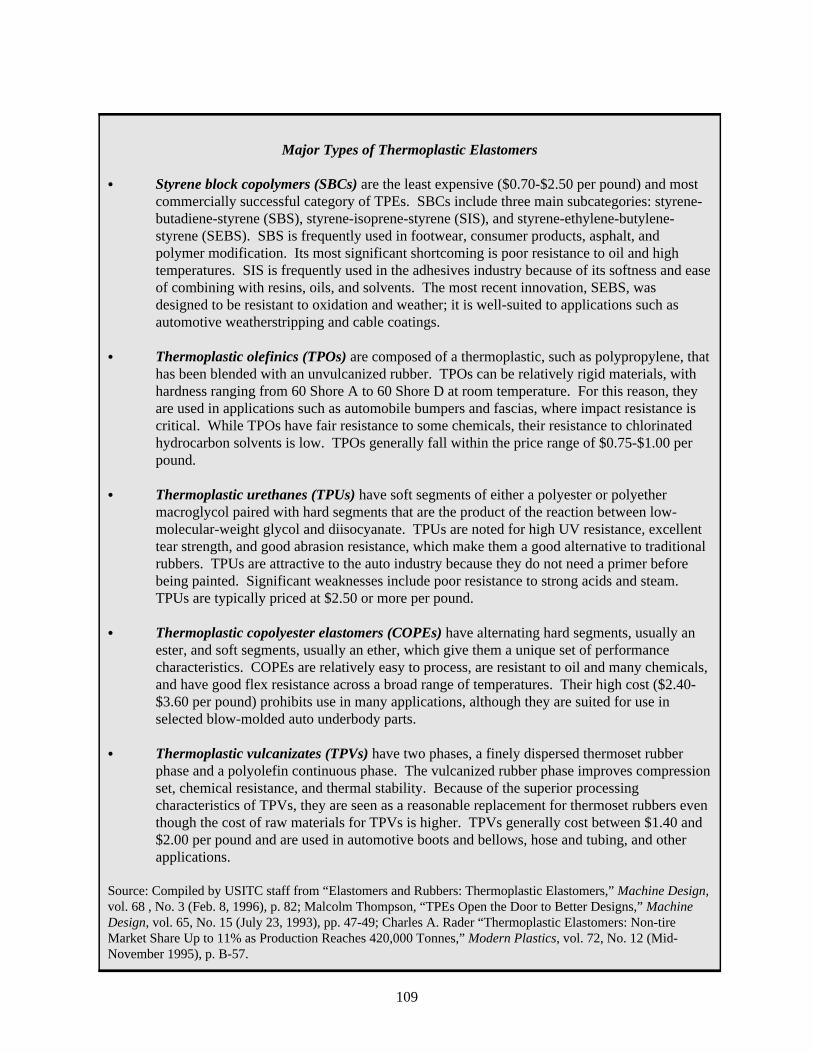
109
Major Types of Thermoplastic Elastomers
C Styrene block copolymers (SBCs) are the least expensive ($0.70-$2.50 per pound) and mostcommercially successful category of TPEs. SBCs include three main subcategories: styrene-butadiene-styrene (SBS), styrene-isoprene-styrene (SIS), and styrene-ethylene-butylene-styrene (SEBS). SBS is frequently used in footwear, consumer products, asphalt, andpolymer modification. Its most significant shortcoming is poor resistance to oil and hightemperatures. SIS is frequently used in the adhesives industry because of its softness and easeof combining with resins, oils, and solvents. The most recent innovation, SEBS, wasdesigned to be resistant to oxidation and weather; it is well-suited to applications such asautomotive weatherstripping and cable coatings.
C Thermoplastic olefinics (TPOs) are composed of a thermoplastic, such as polypropylene, thathas been blended with an unvulcanized rubber. TPOs can be relatively rigid materials, withhardness ranging from 60 Shore A to 60 Shore D at room temperature. For this reason, theyare used in applications such as automobile bumpers and fascias, where impact resistance iscritical. While TPOs have fair resistance to some chemicals, their resistance to chlorinatedhydrocarbon solvents is low. TPOs generally fall within the price range of $0.75-$1.00 perpound.
C Thermoplastic urethanes (TPUs) have soft segments of either a polyester or polyethermacroglycol paired with hard segments that are the product of the reaction between low-molecular-weight glycol and diisocyanate. TPUs are noted for high UV resistance, excellenttear strength, and good abrasion resistance, which make them a good alternative to traditionalrubbers. TPUs are attractive to the auto industry because they do not need a primer beforebeing painted. Significant weaknesses include poor resistance to strong acids and steam. TPUs are typically priced at $2.50 or more per pound.
C Thermoplastic copolyester elastomers (COPEs) have alternating hard segments, usually anester, and soft segments, usually an ether, which give them a unique set of performancecharacteristics. COPEs are relatively easy to process, are resistant to oil and many chemicals,and have good flex resistance across a broad range of temperatures. Their high cost ($2.40-$3.60 per pound) prohibits use in many applications, although they are suited for use inselected blow-molded auto underbody parts.
C Thermoplastic vulcanizates (TPVs) have two phases, a finely dispersed thermoset rubberphase and a polyolefin continuous phase. The vulcanized rubber phase improves compressionset, chemical resistance, and thermal stability. Because of the superior processingcharacteristics of TPVs, they are seen as a reasonable replacement for thermoset rubbers eventhough the cost of raw materials for TPVs is higher. TPVs generally cost between $1.40 and$2.00 per pound and are used in automotive boots and bellows, hose and tubing, and otherapplications.
Source: Compiled by USITC staff from “Elastomers and Rubbers: Thermoplastic Elastomers,” Machine Design,vol. 68 , No. 3 (Feb. 8, 1996), p. 82; Malcolm Thompson, “TPEs Open the Door to Better Designs,” MachineDesign, vol. 65, No. 15 (July 23, 1993), pp. 47-49; Charles A. Rader “Thermoplastic Elastomers: Non-tireMarket Share Up to 11% as Production Reaches 420,000 Tonnes,” Modern Plastics, vol. 72, No. 12 (Mid-November 1995), p. B-57.

16Extrusion, a common plastics processing technique, involves heating the material in acylinder and then forcing it through a die with a rotating screw. Sheets, rods, bars, and tubes canbe made by extrusion. Douglas M. Considine, ed., Chemical and Process TechnologyEncyclopedia (New York: McGraw-Hill Book Company, 1974), p. 884.
17Injection molding is a process in which granulated thermoplastic materials are heated andthen forced into a mold of the desired item. Usually the molds are standardized, which limits thepart sizes and shapes that can be made. Considine, ed., Chemical and Process TechnologyEncyclopedia, p. 883.
18Reisch, “Thermoplastic Elastomers,” p. 11.19Peter Mapleston, “New Grades and Processes Expand TPE Capabilities,” Modern Plastics,
vol. 73, No. 5 (May 1996), pp. 64-65.
110
Table 1North American TPO usage in cars and light trucks for 1995, and projected usage for 2000and 2005, in million pounds; annual growth rate, 1995-2005
Application 1995 2000 2005
Annual growthrate, 1995-2005
(Percent)
Type of part: Exterior: Bumper systems (incl. fascia, trim, strips) . . . . . 100.0 220.0 280.0 10.8 Cladding, side trim . . . . . . . . . . . . . . . . . . . . . . . 20.0 35.0 35.0 5.8 Wheel flares . . . . . . . . . . . . . . . . . . . . . . . . . . . . 6.0 6.5 6.8 1.2 Front grilles . . . . . . . . . . . . . . . . . . . . . . . . . . . . . 3.0 8.0 12.0 14.9 Other trim . . . . . . . . . . . . . . . . . . . . . . . . . . . . . . 18.5 22.6 28.5 4.4 Subtotal, exterior parts . . . . . . . . . . . . . . . . 147.5 292.1 362.3 9.4 Interior: Airbag cover . . . . . . . . . . . . . . . . . . . . . . . . . . . . 1.8 6.3 8.1 16.3 PVC skin replacement . . . . . . . . . . . . . . . . . . . . 0 10.0 20.0 (1) Other interior . . . . . . . . . . . . . . . . . . . . . . . . . . . . 0 4.0 6.0 (1) Subtotal, interior parts . . . . . . . . . . . . . . . . . 1.8 20.3 34.1 34.2 Underhood, Body: Air intake (blow mold) . . . . . . . . . . . . . . . . . . . . . 13.4 18.3 22.0 5.1 Boot, bellows (blow mold) . . . . . . . . . . . . . . . . . . 0.2 0.4 0.6 11.6 Splash shields . . . . . . . . . . . . . . . . . . . . . . . . . . 2.0 4.0 6.0 11.6 Subtotal, underhood/body parts . . . . . . . . . . 15.6 22.7 28.6 6.2 Total 164.9 335.1 425.0 9.9
Comparative measures: Vehicles produced (million) . . . . . . . . . . . . . . . . . . 13.0 13.3 13.5 0.4 Pounds/vehicle . . . . . . . . . . . . . . . . . . . . . . . . . . . 12.7 25.2 31.5 9.5
1 Not applicable because the quantity is zero for the initial year under consideration.
Source: Bernie Miller, “TPO Takes Fast Lane to Big-time Applications,” Plastics World, vol. 53,No. 10 (October 1995), pp. 42-48.
Processing Advantages of TPEs
The major advantages of TPEs over thermoset rubbers relate to processing, particularly theoption of processing TPEs on equipment that is used for plastic extrusion16 or injectionmolding.17 By comparison, traditional rubbers require slow batch processing using capital-intensive machinery.18 TPEs also can be made in specific grades because they are producedin continuous processes, whereas it is much more difficult to achieve consistentspecifications for the materials produced in batch processing because of slight variations inthe conditions for each batch.19

20Vulcanization is the industrial process in which raw rubber is heated with sulphur andcertain other chemicals to achieve the crosslinks that “set” thermoset rubbers. Heinisch,Dictionary of Rubber, p. 189.
21Thermoforming is a process in which a sheet of material is heated and then pulled (byvacuum, pressure, or a mechanism) onto a form or mold. This process is effective for low-costparts with large surface areas; the costs of tooling are low and there are no restrictions on partsize. Considine, ed., Chemical and Process Technology Encyclopedia, p. 884.
22Sherman, “New Applications Breed New Ways to Process TPOs,” p. 16.23Miller, “TPO Takes Fast Lane,” p. 43.24A polymer based on any of the olefins, which are carbon-based molecules with the basic
formula of CnH2n.25A thermoplastic polymer of propylene.26Sherman, “New Applications Breed New Ways to Process TPOs,” p. 16.27In blow molding, a thin cylinder, called a parison, is extruded and then inserted in a split
mold; the parison is then pneumatically pressed into the mold to produce a thin, hollow part. Considine, ed., Chemical and Process Technology Encyclopedia, p. 884.
28Estimates of cost savings associated with TPE processing are not available.29Rader, “Thermoplastic Elastomers,” p. B-58.30Ibid. 31Eller, “Interiors,” p. 52.32Eller, “Interiors,” p. 49.33An automobile part that connects the steering shaft to the steering gear and serves to isolate
the driver (via the steering wheel) from imperfections in the driving surface.34“A New Feel for the Road,” Automotive Production, vol. 108, No. 7 (July 1996), p. 22.
111
Thermoset rubber is limited in its processing methods, in part because of low temperatureconstraints required to prevent premature vulcanization.20 By comparison, a number of morespecialized processing techniques are possible with certain TPEs. For example, film andsheet extrusion and thermoforming21 processes are being developed to use TPOs in “soft-skin” applications in car interiors. After extrusion, the TPO is then thermoformed to a morerigid material, thereby improving the feel of the end product.22 Although the thermoplasticpolyvinyl chloride (PVC), which has excellent tactile characteristics, is currently the mostcommon material used for thermoformed products, TPO use in mid-priced cars is growingin popularity because of its superior UV resistance, better color stability, and lower weight.23
Low-pressure injection molding is also opening TPOs to new soft-feel applications. In thisprocess, a composite of TPO skin and polyolefin24 foam is placed in a mold, andpolypropylene25 is then injected under low-pressure conditions. In one step, the producergenerates a finished part with no adhesive materials required.26
Blow molding,27 which is not an option for thermoset article manufacturers, also has beenpursued by TPE producers. Because of easier processing and the ability to generateextremely thin parts, blow-molded TPEs reportedly offer significant cost savings28 overinjection-molded hollow parts made of thermoset rubbers.29 For this reason, TPEs arebecoming a popular material choice for hollow products, such as bottles, convoluted boots,and bellows.30
Innovations in TPE processing techniques, especially molding, are likely to produce anincrease in part consolidation, meaning that one single large part takes the place of severalsmaller parts.31 Parts consolidation is attractive to the auto industry because it reducesassembly and disassembly cost and leads to improved energy efficiency.32 For example, anew design for an intermediate steering shaft33 that incorporated TPE components reducedthe number of parts from 13 to 3; this lowered the cost of the product by about 20 percent.34

35Rader, “Thermoplastic Elastomers,” p. B-58.36For more information on the recycling of post-industrial and post-consumer TPOs to
produce resins for use in automobiles, please see the following journal article: Lindsay Brooke,“Like a Virgin,” Automotive Industries, vol. 177, No. 4 (April 1997), pp. 105-109.
37Mapleston, “New Grades and Processes,” p. 65.38Ibid.39Rader, “Thermoplastic Elastomers,” p. B-56.40Estimates of cost savings associated with TPE processing are not available.41Rader, “Thermoplastic Elastomers,” p. B-58.42Reisch, “Thermoplastic Elastomers,” p. 11.
112
TPEs, like all thermoplastic materials, are recyclable. Because of the efforts by industry tominimize processing waste, the ease of recycling TPEs provides a considerable advantageover thermoset rubbers. In processing TPEs, scrap can be returned to the manufacturinglines after simple drying and regrinding steps. Individual finished products can be recycledas well, although the process is slightly more involved than for scrap.35 This is attractive tothe auto industry36 since many of the rubber components of a car are discrete parts, and itis therefore possible to remove an individual component and use its material in theproduction of another item.37 The average car, exclusive of tires, contains about 26 poundsof rubber, offering a substantial incentive for automakers to use TPEs in place ofthermosets.38
For parts processors currently producing thermoset rubber articles, there are somedisadvantages to switching to TPE materials. First, the type of equipment used for TPEparts is very different than that which is used for thermosets, requiring a significantadditional investment in new equipment to convert to TPE materials. Even though theupfront cost of thermoplastic processing equipment is less than that for thermosets, theadditional investment and time required to learn a new processing technique may beconsidered prohibitive by a thermoset rubber producer.39 Additionally, raw materials forTPEs are generally more expensive than materials for thermoset rubber production, althoughlower production costs40 reportedly offset this additional expense in many instances.41
The most significant disincentives to using TPEs in place of thermoset rubbers are based onperformance characteristics. High-grade thermoset rubbers offer superior blends of abrasionresistance, flexural strength, deformation resistance, and, most notably, heat resistance whencompared with TPEs. In applications that require strong performance in these areas, theprocessing advantages of TPEs are insufficient to justify their use. For example, becauseTPEs are affected by heat, they are not used in place of thermoset rubbers in automobiletires, currently the largest single application for rubbers.42
Applications in the Auto Industry
Experimentation with new materials is fairly common in the automobile industry, and thecombination of properties of TPEs has attracted automobile and auto parts producers fororiginal equipment (OE) as well as the replacement markets. Initially, TPEs were usedprimarily for applications that had been dominated by thermoset rubbers, but the scope of

43Ibid.44Miller, “TPO Takes Fast Lane,” p. 43.45Jim Callari, “Playing the Resin Game,” Plastics World, vol. 53, No. 9 (September 1995), p.
115.46John Couretas, “Material Assets: Suppliers of Metals, Plastics Battle for a Bigger Share of
Vehicle Content,” Automotive News, No. 5701 (February 24, 1997), p. 32i.47Estimates of cost savings associated with TPE processing are not available.48Miller, “TPO Takes Fast Lane,” pp. 42-43.49Ibid., p.47.50As indicated in the text box, there is a broad range of TPEs, which vary significantly in
price.51Martin O’Neill, “High-Performance Markets Drive TPU Innovation, Growth,” Modern
Plastics, vol. 74, No. 3 (March 1997), p. 71.
113
uses for TPEs is expanding. Increasingly, applications requiring the characteristics ofthermoplastic materials such as PVC have begun switching to TPEs. TPEs can reportedlyoffer considerable savings to automakers over thermosets on the basis of processing costs,43
and TPE parts can be 15 to 30 percent less expensive than comparable goods of otherthermoplastics.44 Additionally, auto producers’ concern with minimizing vehicle weight,which has been buffered by claims that gas consumption could be lowered by 750,000barrels per day if carmakers were to reduce automobile weight by 25 percent during thisdecade,45 has led to increasing use of plastic materials in place of metals.46
Current Applications
Early, less sophisticated thermoplastics elastomers were chosen mainly for their low cost,low-temperature impact resistance, and potential for recycling. The auto industry found usefor these materials, generally TPOs and SBCs, in applications with low-performancerequirements, such as bumper guards, air dams, wheel well liners, rubstrips, dashboard trim,grommets, and step pads. Recent technical developments have strengthened theperformance of TPOs for use in higher stress automotive products, including bumper fascia,cladding, and side trim. Producers reportedly are able to reduce the wall thicknesses ofthese parts by using TPEs, resulting in cost savings47 and shorter processing times, withsuperior performance over other plastic materials.48
The application of TPOs in the auto industry has expanded to significant interior andunderhood parts as well. The replacement of PVC skins in several key uses, including skinsfor instrument panels, door trim panels, and consoles, is a boon for TPO producers. Thethermoplastic elastomers perform better in several areas, including long-term propertyretention and simplified recycling, when compared with PVC; however, TPEs are nottypically used for soft skins in high-end automobiles because their tactile qualities areconsidered to be inferior to those of PVC.49
Several types of TPEs are high in cost,50 which has limited their use in the auto industry.However, there are cases in which other factors somewhat offset the importance of cost inchoosing a material. For example, glass fiber-reinforced TPUs have been introduced as alighter substitute for steel in vehicle body panels. In addition to offering energy efficiencythrough lower vehicle weight, TPUs have excellent structural integrity, low warpage,dimensional stability, and high paintability (with no primer required).51 High-priced COPEsare generally used only in high-performance parts, such as the constant velocity boot,

52Mapleston, “New Grades and Processes,” p. 65.53Ibid. 54Ibid. 55Information obtained from the Airbag Options website (http://www.airbag.net/) on January
8, 1998.56Mapleston, “New Grades and Process,” pp. 66, 68.57Robert D. Leaversuch, “TPEs Address Emergent Needs in Molded Automotive Interior
Parts,” Modern Plastics, vol. 73, No. 4 (April 1996), p. 93.
114
“where functional integration enables them to replace traditional materials.”52 COPEs alsoare favored over thermosets for these types of parts because the products made from thesethermoplastic elastomers typically do not need to be replaced during the lifetime of thevehicle.53
As the development of TPVs has flourished (detailed below), automakers have foundincreasing use for these materials, such as in the corner sections of window seals. Formerlyan application for thermoset rubber, use of TPVs allows producers to avoid finishing steps,including trimming and bonding, and expedites the overall production process fromapproximately 3 minutes to a matter of seconds.54
In most of the aforementioned parts, a TPE has been used as a replacement for thermosetrubber or another plastic material. However, TPEs are not limited to serving asreplacements for other materials in existing applications. There are some products that havebeen developed with TPEs as the primary materials employed from the outset. For example,airbag designers have used a variety of thermoplastic elastomers in their effort to create aneffective yet inexpensive product. There is still considerable design experimentation to bedone on these parts, especially in light of recently released information on potential hazardsrelated to their use.55 However, the TPE combination of firm yet flexible properties seemsparticularly well-suited for these products. Given the expected magnitude of the market forairbags, this reportedly bodes well for TPE producers.56
Developments and Future Applications
TPE producers have been active in developing highly specialized materials intended forspecific end uses. There also has been significant research and development of newprocessing techniques to maximize performance characteristics, while minimizing thequantity of material and time required for production of each article. Some significantinnovations in the auto industry are outlined below.
Considerable progress has been made in the area of TPVs. For example, one recentdevelopment is a TPV grade that can be foamed in a water-based extrusion process; thematerial is then used in the production of the hoodseals of a Japanese recreational vehicle.57
In another innovative extrusion process, TPVs are coextruded with another thermoplastic(e.g., polypropylene) to produce a single component with distinct rigid and soft sections.The dual nature of these materials makes them particularly useful for producing seals: therigid segments anchor the seal in place while the soft segments perform the sealing function. Given the wide variety of automotive seals, each with particular requirements dependingon the section of the vehicle involved, there is likely to be considerable material and processdevelopment in this area. Industry experts have predicted that auto seal producers will

58Robert D. Leaversuch, "New Applications Extend End-Use Penetration,” Modern Plastics,vol. 74, No. 1 (January 1997), p. 75.
59Patrick Toensmeier, “TPE Formulations Show New Versatility,” Modern Plastics, vol. 72,No. 5 (May 1995), p. 75.
60The name of this processing technique reflects the role of robots in shaping the extrudedmaterial.
61According to an auto industry expert, an automotive belly pan is used to cover the bottom ofan automobile, thereby smoothing airflow under the vehicle and reducing noise.
62“TPE Robotic Extrusion,” Machine Design, vol. 69, No. 2 (Jan. 30, 1997), p. 108.63Estimates of cost savings associated with TPE processing are not available.64“Robotic Extrusion Molds Soft Materials over Rigid Substrates,” Machine Design, vol. 69,
No. 11 (June 5, 1997), p. 96.65Reisch, “Thermoplastic Elastomers,” p. 13.66Rader, “Thermoplastic Elastomers,” p. B-58.
115
continue to pursue easily processed, low-priced replacements for the thermoset rubberscurrently in use.58
TPUs are often considered to be too expensive for use in most auto parts, especiallycompared with lower priced TPOs and TPVs. However, there has been substantial researchon the possibility of alloying TPUs with any of several lower grade materials. The pricereduction could be significant enough to warrant such combinations, in spite of thecompromise on performance.59
A new processing technique that looks promising for the production of a variety of autoparts employs robotic60 extrusion technology to cover hard materials with a soft TPE profile.The innovation was first used in Europe to produce an automotive belly pan,61 and auto partsmanufacturers are anticipating a wide range of new applications, including engineencapsulation parts, sunroof profiles, and edged protection for metal parts.62 Using thistechnique, the TPE is extruded through a flexible, heated hose; robots shape the profile tothe rigid substrate, which can be made of any material that can withstand the heat andmechanical constraints of the process. With minor modifications to the robot’s program,part specifications can be altered to meet a wide variety of needs. By comparison with theinjection molding methods (see footnote 17) that are used in similar applications, roboticextrusion reportedly lowers tooling costs,63 gives flexibility to adjust to production ofdifferent parts, produces tight tolerances, and allows for a variety of hollow shapes.64
Outlook for TPE Producers
The growing popularity of TPEs is not limited to the auto industry. Several other sectorsalso are expected to demonstrate high average annual growth rates for TPE use during1995-2000 (table 2), even surpassing growth in the auto industry. Although the autoindustry is likely to continue as the leading consumer of TPEs, medical products will be aparticularly strong area of growth, followed by consumer products and construction.65 TPEsoffer the medical industry considerable benefits over thermoset rubbers on toxicologicalgrounds; certain unhealthful chemical additives required for the vulcanization process, suchas heavy metals (e.g., tellurium and selenium) and aromatic hydrocarbons (e.g., dibenzoyl-p-quinone dioxime), are unnecessary in production of TPEs.66

67The IISRP website (http://www.iisrp.com/) on September 4, 1997.68However, it should be noted that these developments arose prior to the recent economic
problems in Asia, and at this time there is no firm indication as to how TPE consumption will beaffected.
69The Economist Intelligence Unit, “World Rubber Trends and Outlook,” ch. in RubberTrends: The Worldwide Rubber Industry, 1st quarter 1997 (London: The Economist IntelligenceUnit, 1997), p. 21.
116
Table 2Estimated world growth for thermoplastic elastomers, by industry, 1995-2000
Industry sector 1995 2000Average
annual growth
----(Million pounds)----- (Percent)
Motor vehicles . . . . . . . . . . . . . . . . . . . . . . . . . . . 798 1,133 7.3Footwear . . . . . . . . . . . . . . . . . . . . . . . . . . . . . . . . 503 593 3.3Industrial machinery and equipment . . . . . . . . . . . 463 653 7.1Consumer products . . . . . . . . . . . . . . . . . . . . . . . 236 346 8.0Wire and cable . . . . . . . . . . . . . . . . . . . . . . . . . . . 130 165 4.9Medical products . . . . . . . . . . . . . . . . . . . . . . . . . 99 174 11.9Construction . . . . . . . . . . . . . . . . . . . . . . . . . . . . . 62 90 7.7Other . . . . . . . . . . . . . . . . . . . . . . . . . . . . . . . . . . . 44 64 7.8 Total . . . . . . . . . . . . . . . . . . . . . . . . . . . . . . . . 2,335 3,218 6.6Source: Marc S. Reisch, “Thermoplastic Elastomers Target Rubber and Plastics Markets,”Chemical and Engineering News, vol. 74, No. 32 (August 5, 1996), p. 13.
Regional Consumption
North America is currently the leading regional consumer of TPEs in the world (table 3),which is consistent with its position as the leading consumer of rubbers. According to theInternational Institute of Synthetic Rubber Producers, North American consumption of TPEswas expected to grow at a high rate during 1995-97, especially in comparison with that ofthe second largest consumer, Western Europe. The tepid projected growth in consumptionfor Western Europe has been attributed to the region’s sluggish economy. Latin America,the Commonwealth of Independent States, and the Middle East and Africa all showedgradual growth during 1995-97.67 Data on Asian TPE consumption are not available;however, as indicated by recent business developments (see following section), growth inAsian markets would seem likely.68 China in particular has been a significant consumer ofTPEs for use in its footwear industry.69

70“AES, an Instant Giant, Says It Will Catalyze Big Expansion of TPE Field,” ModernPlastics, vol. 68, No. 3 (March 1991), p. 16.
71Information obtained from the DuPont Dow website (http://www.dupont-dow.com/) onSept. 16, 1997.
72“Business Briefs,” Modern Plastics, vol. 73, No. 3 (March 1996), p. 19.73“TSR Invests in China, Thailand, U.S.” Chemical Week, vol. 158, No. 10 (March 13, 1996),
p. 21.74“Kuraray May Build Texas Plant,” Chemical Week, vol. 159, No. 14 (April 9, 1997), p. 12.
117
Table 3TPE consumption, by region, in million pounds, 1995-97
Region 1995 19961 19972
Average annualgrowth, 1995-97
(percent)
North America . . . . . . . . . . . . . . . . . . . . . . . . . . 831.0 913.6 976.4 8.4Western Europe . . . . . . . . . . . . . . . . . . . . . . . . 694.3 694.3 722.9 2.0Latin America . . . . . . . . . . . . . . . . . . . . . . . . . . 26.7 30.9 33.1 11.3Commonwealth of Independent States . . . . . . 19.8 22.0 22.0 5.4Middle East and Africa . . . . . . . . . . . . . . . . . . . 13.2 13.9 14.8 5.9World . . . . . . . . . . . . . . . . . . . . . . . . . . . . . . . . 1,924.1 2,027.7 2,135.7 5.4 1 1996 figures are based on partial year data. 2 1997 figures are forecasts by IISRP.
Source: Compiled by USITC staff from data obtained from the International Institute of SyntheticRubber Producers’ website (http://www.iisrp.com/) on Sept. 4, 1997.
Business Developments for TPE
Business activity involving TPE has thrived recently. While the following is not anexhaustive list of business developments in TPEs, the information cited is indicative of thegrowth anticipated by the chemical industry.
In North America, expansion of TPE capacity is ongoing. An earlier indication thatthermoplastic elastomers were becoming serious competitors with rubber and plastics wasthe emergence of a joint venture by two large chemical companies. In January of 1991,Monsanto Chemical Co. and Exxon Chemical Co. joined forces to form AdvancedElastomer Systems (AES), a company intended to draw on the parent companies’ strengthsto develop innovative thermoplastic elastomers.70 Similarly, on April 1, 1996, DuPont DowElastomers was created as a joint venture between DuPont Chemical Co. and Dow ChemicalCo., with a focus on the creation of specialized elastomer materials.71
Other developments followed. Bergmann Kunststoffwerk of Germany, a part of the M.A.Hanna Group of Ohio, has invested in a new production facility in Spain. The site willincrease the company’s TPE production by 25 percent.72 Additionally, an Asian company,Taiwan Synthetic Rubber (TSR), purchased a 30 percent stake in a U.S. TPE producer, J-Von. TSR plans to use the investment as an opportunity to expand its TPE technicalcapabilities as well as its U.S. marketing experience. Conversely, J-Von expects thearrangement to help gain entry to the Asian market, for both sales and investment.73 Another Asian company, Kuraray (Japan), has pursued the possibility of building a TPEplant in Texas, given the significant demand for its products in the United States andEurope. After 3 years of marketing in the American and European markets, Kuraray isinterested in building a production facility to supplement its 10,000 metric ton (about 22million pounds) plant in Japan, ideally with a geographical advantage for the U.S. market.74
With the stated goal of capturing 20 percent of the world TPE market, DSM (Netherlands)

75“DSM Starts Up Rubber TPEs,” Chemical Week, vol. 159, No. 14 (April 9, 1997), p. 30.76“TPE Supplier Acquired by Taiwan Companies,” Modern Plastics, vol. 73, No. 3 (March
1996), p. 23.77“Business Briefs,” Modern Plastics, vol. 73, No. 3 (March 1996), p. 23.78“ DuPont Dow Slates Singapore for Base,” Modern Plastics, vol. 73, No. 6 (June 1996),
p. 25.
118
recently invested in increased production capacity at its plant in Belgium; the new capacitytriples the previous level to 15,000 metric tons (about 33 million pounds) annually.75
In March 1996, it was reported that the Taiwanese TPO and TPU producer PolystarEngineering Plastics Co. was acquired by two other Taiwanese companies: Tong YangIndustry Co., an auto parts producer, and Integral Chemistry. Reportedly, Tong Yang soughta local source of TPOs for its annual production of 600,000 bumpers, the majority of whichare exported to the United States, and 120,000 instrument panels. Prior to this acquisition,Tong Yang was importing about 13.2 million pounds of TPOs annually.76 In Iwakuni,Japan, the Toyobo Co. built a plant designed for production of 7.7 million pounds ofcopolyester elastomer annually. Without the new facility, Toyobo was already producing5.5 million pounds of TPEs per year, most of which were sold to Southeast Asian auto partsproducers.77 Additionally, Dow Elastomers established its Asian headquarters in Singaporein 1996 to begin marketing TPE in the region. About 15 percent of the company’s sales areto the Asia-Pacific region, and there is an expectation for this percentage to rise to 25 to 30percent by 2001, as significant growth is anticipated in consumption of wire and cable,automobiles, and footwear. DuPont Dow has long-term plans to set up production facilitiesin the region.78
Conclusions
The prospects for TPEs in the auto industry seem promising. As cars continue to becomelighter in weight and more energy efficient, automakers and parts producers are expectedto continue to experiment with new and innovative materials. Research and developmentto find more efficient, faster, and more effective processing methods is also likely to persistas an integral facet of design for the auto industry. Moreover, as parts consolidation andrecycling of parts (and materials) become increasingly important objectives, the autoindustry will continue to experiment with alternative materials. Because of the ease ofprocessing, potential for recycling, and performance characteristics of thermoplasticelastomers, the auto industry can be expected to find increasing use for these materials inthe future. Average annual growth of TPE use in the motor vehicle sector between 1995 and2000 is estimated at 7.3 percent, projected to reach 1.1 billion pounds in 2000 (table 2). InNorth America, TPOs specifically are expected to increase from 165 million pounds in 1995to 335 million pounds in 2000 and 425 million pounds in 2005 (table 1).
In spite of the optimistic growth rates anticipated for TPE, it should be noted that TPEsremain a fairly small portion of total elastomer (including natural and synthetic thermosetrubber) consumption. Although use of TPEs will continue to grow from a broader scope ofapplications, certain performance constraints, particularly the lack of heat resistance, willcurtail their application in specific areas. As noted earlier, the largest end use for rubber istires, an application for which TPEs are considered unacceptable.

119
World production of TPEs is increasing to keep up with demand, and growth is expected tocontinue at a high rate. Because TPE producers and the auto industry, the largest currentuser of TPEs and frequent driving force for material development, have an establishedrelationship, it does not seem likely the auto industry will encounter a shortage of materialsas a result of the rise in TPE use in other sectors, such as the medical industry. Manypossibilities remain for the auto industry to improve the performance, appearance, andefficiency of its products, and there seems to be a commitment from TPE producers to playa significant role in this process.
1The frame is the most important part in determining the ride characteristics of a bicycle anddraws primary interest when considering alternate materials. Components are all nonframe partsof a bicycle.
2Better quality bicycles are sold mostly through independent dealers and are a distinct marketsegment from the lower quality bicycles that are typically sold by mass merchants such as toy anddepartment stores.
3MMCs are composed of a metal or metal alloy base (called the matrix) and a reinforcingmaterial (usually ceramic) dispersed within the matrix. For a more detailed description ofMMCs, see U.S. International Trade Commission, "Metal Matrix Composites May be Key toMore Efficient Automobiles," Industry, Trade, and Technology Review, May 1993, p. 1.
120
U.S. Bicycle Industry Creates InnovativeProducts Using Metal Matrix CompositesDavid Lundy(202)[email protected]
Competitive cycling has pushed bicycle manufacturers toward theleading edge of technological innovation. Bicycle companies areincreasingly turning to advanced materials, such as metal matrixcomposites (MMCs) in an effort to lighten frames while improvingstrength and stiffness.
Since this article was first published in the Industry, Trade, andTechnology Review of May 1994, the bicycle industry has notsignificantly expanded the usage of MMCs in their products. Theconcluding section of this article updates recent developments.
The U.S. bicycle industry's attempts to improve the performance of bicycle frames andcomponents have led to the aggressive pursuit of alternate materials since the early 1980s.Bicycle frame and component1 design is an engineering compromise between cost andphysical properties (including weight, strength, stiffness, energy absorption, and ease ofmanufacture). These considerations depend on the material used, the configuration of thematerial (i.e., dimensions such as tube diameter and wall thickness), and the configurationof the frame and components. In the 1970s, in virtually all the better quality bicycles,2 steelalloys were used in the frame and aluminum alloys were used in components. Since then,many new materials have been adopted for use in bicycles, but steel and aluminum alloysremain the standards for comparison.
Metal matrix composites (MMCs) are one of the most recent innovative materials to beconsidered for use in bicycles.3 U.S. produced, MMC-containing bicycles have beenavailable in the U.S. and foreign markets for several years. These bicycles are priced at theupper end of the better quality market and will likely stay expensive. However, thiscommercialization is an important initial step in gaining acceptance of the material by thebicycle industry and consumers, and building a base for further adoption. This articleexamines innovation and materials use by the U.S. bicycle industry, the U.S. bicycle marketand industry structure, and the bicycle MMC infrastructure. It concludes with a discussionof the outlook for more widespread adoption of MMCs.

4The mountain bicycle was actually invented during the mid-1970s, although seriouscommercialization did not start until the 1980s. In this article, the term mountain bicycle refers toa style of bicycle rather than bicycle use. Compared with a road bicycle, this bicycle has a sturdierframe, wider tires, an upright riding position, and more gears.
5According to an industry source, the use of aluminum-alloy frames originated from researchat the Massachusetts Institute of Technology, where it was found that aluminum's lower degree ofstiffness compared with steel could be offset by using larger diameter frame tubes. The firstcompany to produce bicycles with aluminum-alloy frames was founded in the United States in1978.
6Published figures on the composition by frame material of the U.S. better quality bicyclemarket are not available. Figures used in this article represent rough estimates made byrepresentatives of two U.S. bicycle producers.
7Steel-alloy tubes can be produced with extremely thin walls, and a frame with these tubescan be nearly as light as any alternative material frame. However, these tubes are also relativelyexpensive to produce. Designing a bicycle involves tradeoffs between material and fabrication
(continued...)
121
Design and Material Innovation by the Bicycle Industry
Since the beginning of the 1980s, the U.S. bicycle industry has generated a large number ofinnovative products, using a wide variety of materials and designs. The mountain bicyclewas one of the most notable innovations,4 creating a new sport (i.e., off-road bicycling) anda new design configuration that is extremely popular with consumers; this type of bicyclenow accounts for roughly two-thirds of all U.S. better quality bicycle sales.
One recent design innovation is the bicycle with a suspension system. It gives a smootherride and better handling on difficult terrain, but adds a significant amount of material to abicycle. Strong, light-weight parts are essential in designing a viable suspension bicycle witha reasonable overall weight.
This high degree of technical innovation has been accompanied by an intense focus on theadoption of alternate materials. New materials, such as aluminum alloys (for frameapplications), metal matrix and carbon fiber composites, aluminum-lithium alloys, titaniumalloys, and beryllium alloys, have been developed for use in bicycles. During the 1984Summer Olympics in Los Angeles, U.S. bicycle team members used aluminum-alloy framebicycles, which helped to validate these types of frames, and generated broad interest inother alternative materials for frames.5 The success of Greg LeMond, the first U.S. racer towin the Tour de France and a strong proponent of innovation, also furthered interest inalternate materials in the United States. During 1985-86, bonding technology improveddramatically, allowing engineers greater flexibility in joining dissimilar materials (a criticaltechnology for making carbon fiber composite frames).
Material Alternatives
Steel-alloy frame bicycles still dominate the sales of better quality bicycles, accounting forabout 85 to 90 percent by quantity of the U.S. market.6 Steel's strength, stiffness, and lowcost makes it an attractive material, but its relative weight is a significant performancedeterrent.7 The aluminum-alloy frame bicycle is the most popular nonsteel type. With the

7(...continued)costs.
8In contrast, most frames made of metal and MMCs do not need lugs; the frame tubes aresimply welded to each other.
122
development of oversize tubing to compensate for aluminum's lower degree of stiffness,these bicycles have become the most popular alternative to steel-alloy frame types,accounting for approximately 9 to 11 percent of the U.S. market.
Another popular alternative for bicycle frames and components is carbon fiber compositematerial, which may be the best material to minimize weight. The material has beendeveloped extensively for road bicycles. Bicycles with carbon fiber composite framesaccount for from 1 to 2 percent of the U.S. market. However, durability, a significant designconsideration, has limited the use of carbon fiber composites for mountain bicycle frames;relatively large lugs (usually made of aluminum) must be used where the tubes intersect togive the frame sufficient strength, which tends to diminish the overall weight savings.8
Recently, mountain bicycle producers have developed new manufacturing processes to avoidthe heavy-lug problem. One company has developed a carbon fiber composite lug andanother company has developed a process to make a one-piece carbon fiber compositeframe. However, these bicycles are at the high end of the carbon fiber composite bicycleprice range.
Recently, titanium has received considerable promotion in the bicycle industry for use in theproduction of both frames and components. High cost has been a major deterrent to its usein the past, but exports from Russia have greatly increased the supply of titanium on worldmarkets and its price has decreased considerably in the last few years. Titanium-alloy framebicycles account for less than 1 percent of the U.S. market.
MMCs are relatively new to the bicycle industry. First used commercially in a mountainbicycle frame in 1991, MMC-frame bicycles currently account for less than 1 percent of theU.S. market. Three companies supply MMCs to the bicycle industry for frame applications--Duralcan (subsidiary of the Canadian aluminum company ALCAN), DWA Composites(owned by British Petroleum), and Alyn Corp. (a U.S. ceramics and composites company).The MMCs made by these companies have a matrix of aluminum and, respectively, areinforcing material of aluminum oxide, silicon carbide, and boron carbide particles.Aluminum MMCs can be used as substitutes for conventional steel alloys to achieve asignificant weight reduction, and as substitutes for aluminum alloys (without using oversizetubing) to significantly improve strength and stiffness. Other important advantages of theseMMCs, compared with aluminum alloys, include better fatigue resistance, superior energyabsorption, and improved friction performance.
Table 1 shows a relative ranking of several important properties of these materials. Bicycleframe and component design involves tradeoffs in properties when selecting materials. Forexample, one of the tradeoffs in steel alloys is low cost versus a high specific weight.

123
Table 1Relative ranking of bicycle frame materials1
Material propertiesTypical Specific Specific Process-
Material composition(s) Cost2 weight3 Strength stiffness4 ability5
Steel alloys . . . . . . . . . 0.80-1.15% Cr 1 7 1 5 10.35-0.60% Mn0.15-0.35% Si0.15-0.25% Mo0.27-0.34% CBalance Fe
Aluminum alloys . . . . 0.25-6.1% Zn 2 2 5 7 20.8-2.9% Mg0.1-2.0% Cu0.35-0.8% Si0.4-0.7% Fe0.15-0.7% Mn0.04-0.35% Cr0.01-0.2% TiBalance Al
Carbon fiber composites . . . . . . . Carbon fibers
in resin epoxy 6 1 3 1 7
Titanium alloys . . . . . . . . . . . 3.0% Al 7 6 2 6 3
2.5% V
Duralcan MMC . . . . . . . . . . . 85% Al 3 4 5 4 4
15% Al oxide
DWA MMC . . . . . . . . 80% Al 5 5 4 3 520% Si carbide
Alyn MMC . . . . . . . . . 88% Al 4 3 4 2 612% B carbide
1 The lower number indicates an advantage, i.e., lower cost, lower specific weight, higher strength, higher specific stiffness, or better processability. 2 Includes the cost of materials and fabrication. 3 Weight divided by volume. 4 Stiffness divided by density. 5 Processability refers to ease of shaping and joining the material.
Note.--Cr is chromium, Mn is manganese, Si is silicon, Mo is molybdenum, C is carbon, Fe is iron, Al is aluminum, Zn is zinc, Mg is magnesium, Cu is copper, Ti is titanium, V is vanadium, and B is boron.
Source: Mountain Bike, Jan. 1994; compiled by staff of U.S. International Trade Commission.

9A range of prices applies to all types of bicycles, depending on the configuration of theframe material and the quality of components. Thus, a steel-frame bicycle with a suspensionsystem and high-quality components can easily cost more than $1,500, a high-end carbon fibercomposite-frame bicycle more than $2,000, and a titanium-alloy frame bicycle more than $5,000. Price data from "Super Spec '94," Bicycling, Mar. 1994, pp. 105-120; Performance Bicycle Shopsales brochure; and Stephen C. Levin, "Composites and Bicycles: Market Diversification inAction," Proceedings of the 38th International Symposium of the Society for the Advancement ofMaterials and Process Engineering, May 1993, p. 4.
10An additional 10 million bicycles composed the total 1993 U.S. market, but these are thelower quality, low-cost types.
11Levin, "Composite Bicycles," and the National Bicycles Dealers Association.
124
U.S. Bicycle Market and Industry Structure
Bicycles with frames of alternate materials are significantly more expensive than steel-alloyframe bicycles. Good quality steel-alloy frame bicycles retail in the United States for $300to $400, compared with $600 for aluminum-alloy frame bicycles, $800 for carbon fibercomposite-frame bicycles, $900 for MMC-frame bicycles, and $1,600 for titanium-alloyframe bicycles.9
Annual sales in the United States of better quality bicycles are estimated at slightly morethan 3 million units, sold primarily through independent bicycle dealers.10 The breakdownof sales for 1992 by retail price category is as follows:
Retail price range Units sold
Less than $400 . . . . . . . . . . 2,000,000$400 - $750 . . . . . . . . . . . . . 750,000$750 - $1,000 . . . . . . . . . . . 300,000$1,000 - $1,200 . . . . . . . . . . 75,000Greater than $1,200 . . . . . . . 50,000 Total . . . . . . . . . . . . . . . . 3,175,000
The total better quality bicycle market in the United States, including sales of bicycles,components, and services, is approximately $2 billion.11
The lowest cost MMC-frame bicycle falls into the upper end of the $750-$1,000 pricesegment. Other models currently available cost over $1,000. Therefore, at current prices, itappears that MMC bicycles are competitive in only a relatively small segment of the betterquality market.
The structure of the world bicycle industry is strongly influenced by the labor-intensivenature of producing better quality bicycles. Many bicycle producers use foreign assemblyoperations, especially in Taiwan and more recently in China, to take advantage of lessexpensive labor. Although the U.S. bicycle industry is a world leader in bicycle innovations,few better quality bicycles are actually produced in the United States. Imports supply mostof the better quality U.S. bicycle market, but many of these imports are U.S. designed andengineered bicycles sold under U.S. company labels. Figures for U.S. production of betterquality bicycles are not available, but industry sources estimate such production accounts

12Export figures are official statistics of the U.S. Department of Commerce. Some industryrepresentatives believe that most U.S. exports classified as "other" bicycles were larger bicycles. Exports of such bicycles averaged 317,000 units annually during 1991-93, and Canada andWestern Europe combined accounted for about one-third of these exports in 1993.
13Sintering is a process of densifying and bonding the constituent powders by applying heat. 14In hot isostatic pressing, interparticle bonding and densification of a material is achieved by
applying high pressure and high temperatures.
125
for only 10 to 15 percent (about 300,000 to 450,000 units) of the U.S. market for thesebicycles, and is concentrated in bicycles priced above $800.
U.S. exports of larger bicycles (those with both wheels over 25 inches in diameter, whichincludes most of the popular styles of bicycles) have averaged over 200,000 units per yearduring 1991-93.12 The principal markets were Western Europe and Canada, which togetheraccounted for about three-quarters of such exports in 1993. The relative portion by qualityof these exports is not available.
Japanese companies dominate production of components for better quality bicycles,including components that are part of the original equipment of bicycles, and componentsthat are sold to replace original equipment. Japanese component producers also have foreignassembly operations in some Southeast Asian countries to take advantage of less expensivelabor. Most better quality bicycles have Japanese components, whether made in the UnitedStates or in foreign countries (for U.S. or foreign companies).
The Bicycle MMC Infrastructure
There are a number of companies in the United States and Canada that are involved in thebicycle MMC infrastructure, including MMC production, frame fabrication, componentproduction, and assembly operations. In contrast to most of the better quality bicycles soldin the U.S. market, MMC-frame bicycles are produced in the United States.
Duralcan has a plant in Canada that produces aluminum MMCs, using a relatively straight-forward technique of mixing the reinforcement material in molten aluminum and castingsemifabricated shapes. The Duralcan material has the simplest and least expensiveproduction process, but its properties are not as significant an improvement over thealuminum matrix material as the other MMCs. The DWA MMC is produced by mixingpowders of the two constituents together and sintering the material.13 The Alyn Corp.material, called boralyn, is produced using a proprietary method of mixing the metal andceramic material and hot isostatically pressing the mixture into a semifabricated form.14
These MMCs are then extruded to form tubes or other shapes.
The Duralcan material is the most extensively developed MMC and is the most widely used.A company in California, Specialized Bicycle Components (SBC), uses this MMC inmountain bicycle frames, which are built by another U.S. company, Technical Dynamics,according to SBC design specifications. SBC assembles the frames into finished bicycles.Current production of the MMC bicycle is about 20,000-25,000 units per year, of whichapproximately 35 percent are exported to Western Europe (mostly Germany, UnitedKingdom, and Italy). The least expensive MMC-frame bicycle produced by SBC retails forapproximately $900.

15Specialized Bicycle Components representative, telephone interview by USITC staff,Washington, DC, Jan. 12, 1994.
16DWA Composites representative, telephone interview by USITC staff, Washington, DC,Jan. 13, 1994.
17In this process, silicon carbide powders are molded into a preform and molten aluminum isallowed to infiltrate into the pores of the preform, forming the MMC.
18LSI representative, telephone interview by USITC staff, Washington, DC, Apr. 20, 1994.
126
SBC has been developing its MMC bicycles for 7 years. The goal was to produce amountain bicycle that mirrors the performance of a racing mountain bicycle, but with areasonable retail price. The company considered a number of alternate materials for theirmountain bicycle frames, including aluminum-lithium alloys, specially treated aluminum,and other MMCs before deciding to pursue the Duralcan material. Company officialsbelieve the Duralcan material appeared the best suited for mountain bicycle frames becauseof the fatigue resistance, stiffness, and energy absorption effect of the material.15 Thecompany continues to produce a wide range of mountain bicycles with steel frames and alsohas a model with a carbon fiber composite frame (using a lugged design). SBC is alsoexamining the possibility of making certain components, such as seat posts and fork braces,out of the Duralcan MMC.
The boralyn material is currently used in two bicycle models produced by Univega in theUnited States that retail for over $1,400. Sales levels are believed by industryrepresentatives to be small. The Alyn Corp. sells boralyn tubes to Univega, which hasanother company weld the tubes into frames. Several other companies are testing boralynbut have not developed any commercial products.
Currently the DWA material is not used commercially in any bicycle. DWA Composites isdeveloping its MMC in the United States, and is working with several bicycle companiesto develop frames. It expects that bicycles with its MMC will soon be available. Industrysources expect bicycles with DWA MMC frames to retail for approximately $1,000.16
Lanxide Corp., a U.S. advanced materials company, also produces an MMC and isdeveloping MMC bicycle components through a joint venture company called LanxideSports International (LSI). The MMC is composed of aluminum reinforced with siliconcarbide and is produced using Lanxide's proprietary liquid metal infiltration process.17 TheMMC is available in castable ingot form and can be used to manufacture parts usingconventional casting methods. The infiltration process allows for a relatively highpercentage of reinforcement material (above 30 percent) compared with the Duralcan MMC(which is limited to 20 percent reinforcement content) and the company claims its MMC hasbetter properties as a result. LSI has developed prototype components in cooperation withcasting companies. Suspension parts, pedal crank arms, chain rings, and brake system partshave been developed and some of these parts reportedly will be commercially availablewithin one year. LSI plans to sell components to domestic and foreign bicycle andcomponent companies for original and replacement equipment. LSI is also trying to developframe applications for its MMC.18
Several other companies are developing MMCs in the United States for bicycle applications.One company that makes aluminum-alloy bicycle frames is developing MMC frames usingthe Duralcan MMC. Dia-Compe, MC-21 Incorporated, Sun Metal Products, Odyssey Co.,Innovative Bicycle Components, and others are developing bicycle components that useMMCs. Dia-Compe, a U.S. producer of aluminum components, is currently trying to

127
develop markets for MMC components. It purchases parts from MC-21 Incorporated, acompany that manufactures parts using the Duralcan MMC. Dia-Compe believes the MMCmaterial is particularly well suited for components, such as wheel hubs on bicycles withsuspensions (these bicycles need stronger hubs to accommodate the suspension parts) andrims, because the MMC is an excellent braking surface. Although Dia-Compe is still in theinitial stages of developing markets for such components, it has already sold a small numberof test hubs in Europe. Sun Metal Products is close to commercializing wheel rims made outof the Duralcan MMC. Innovative Bicycle Components is using the Duralcan MMC indeveloping wheel hubs and brake parts.
Odyssey Co., a U.S. manufacturer of bicycle components, is also attempting to developMMC parts. This company is developing a cog set (i.e., the rear chain sprockets) formountain bicycles made of the DWA MMC and expects to have a commercial product bymid-1994. The company intends the product for replacement sales (i.e., not as originalequipment) to the high-priced end of the market. The company plans to distribute the cogset in the United States and foreign markets using its existing distribution network.
Many foreign companies are also developing MMC bicycles and components using theDuralcan MMC. One major Japanese bicycle company has developed an MMC-framebicycle prototype and may soon produce it commercially. Another Japanese company anda Taiwanese company are developing an MMC bicycle frame. At least four Europeanbicycle companies are developing MMC applications.
Outlook
The current production of bicycles and components containing MMCs is small, but thetechnical merits of the MMC material are attracting interest among bicycle and componentproducers. Technical experience with MMCs in bicycle applications is only beginning, andMMCs lag behind more established alternative materials, such as aluminum and, to a lesserextent, carbon fiber composites. A considerable amount of development is still needed tofind the optimum applications, designs, and MMC com- position. For example, MMC framedesign parameters, such as tube diameter, wall thicknesses, and tube configuration, whichhave been researched extensively for steel and aluminum alloy frames, have not beenadequately developed. Component design is just beginning to fully consider the potentialof MMCs. Additionally, other MMC compositions (some of which may simply change theamount of reinforcement material in existing MMCs) may prove to be more practical thanthe compositions currently used.
However, there are many more companies producing or evaluating the use of aluminum andcarbon fiber composites or doing both than are dealing with MMCs. Some large bicyclecompanies are not even seriously considering use of MMCs. This hesitation is partly dueto the many material choices available as well as the prospect of making furtherimprovements in the materials already being used.Further development of MMCs for bicycle applications appears likely. Although MMCbicycle production is small compared with the total U.S. market of better quality bicycles,it appears that the market is being successfully developed. Current production is a modest5 to 10 percent of U.S. production of the better quality types of bicycles. MMC bicycles alsoaccount for a small but significant portion of U.S. exports of bicycles. This initialcommercialization has demonstrated that U.S. and foreign markets are receptive to MMCs,

128
and more producers will likely be attracted to these markets. Component production shouldalso increase because MMC properties seem especially advantageous in such applicationsas rims. Lately the development of new markets for MMCs has been spurred by the declinein U.S. defense spending. Companies that developed MMCs for military use are turningto such alternative markets as the bicycle industry to make up for lost sales.
Bicycles containing MMCs are costly, and cost forms a significant barrier to wider use.However, production process improvements and design innovations could effectively lowerthe cost of MMC usage. According to industry sources, there is a strong possibility thatMMC extrusion methods could be improved substantially, which would lower productioncosts. Further, MMCs could be used in less expensive bicycles by designing frames thatcombine MMC tubes in high-stress areas and tubes of cheaper materials in the less stressedareas. MMC components could also be selectively used on less expensive bicycles in onlythe areas of highest stress or wear.
If MMC bicycles and components do become more widespread, U.S. companies are wellpositioned to increase their market share in U.S. and foreign markets. The innovative U.S.industry appears to have a substantial head start over foreign companies. However, intensecompetition is likely from other materials, such as carbon fiber composites and titanium.
Recent Developments
Specialized Bicycle Components continues to sell a mountain bicycle frame made ofDuralcan's MMC and has also recently developed a road racing bicycle made of the samematerial. The bicycle industry remains a minor consumer of MMCs. However, MMCconsumption in the automobile industry appears poised to increase substantially. For moreinformation, see “Metal Matrix Composites May be Key to More Efficient Automobiles”later in this report.

1Weight savings and fuel economy have been cited as reasons for operators of fleet vehiclessuch as trailers, delivery vans (e.g., U.S. Postal Service fleet), and railroad cars to specify morealuminum in their vehicles.
129
Aluminum Product Development and theAutomotive Industry
Charles Yost(202) [email protected]
The automotive sector offers excellent potential for increasedaluminum consumption. Automakers are expanding their use ofaluminum to increase fuel economy and reduce emissions, butprice, supply, manufacturing cost, and recyclability pose concerns.Research and development continues, aided by experience.Aluminum competes with steel; steelmakers have significantlyimproved sheet quality, also through collaborative efforts withautomakers.
This article was first published in the Industry, Trade, andTechnology Review of May 1994. The concluding section updatesrecent developments in the use of aluminum and its competitionwith steel within the automotive sector.
As a single market, the automotive sector probably has the best potential for increases inaluminum consumption during the 1990s. Although consumption of aluminum per carcurrently is relatively low, automakers worldwide are expanding the use of aluminum,driven by concerns about performance, fuel economy, emissions, and materials recyclability.Aluminum companies are striving to capitalize on aluminum's physical and mechanicalproperties. These properties favor aluminum substitution for other metals and materials inautomobile bumper systems, engines and drive trains, heat exchangers, frames, and exteriorpanels. Specific initiatives include joint research, development, and marketing efforts withautomakers. As a result of these efforts, industry analysts predict consumption of aluminumin automobiles will double between 1992 and 2000, to 2.8 billion pounds. This articleexamines aluminum's increasing importance in automobile construction, auto industryefforts to increase its use, and projections for future aluminum use in the auto industry.
Aluminum Use in the Auto Industry
Automakers lightened average car weights by about 25 percent, to about 3,000 poundsduring 1978-80, doubling fuel economy and improving performance. Currently there islimited market-driven impetus to achieve even higher fuel economy in the United States1
because gasoline is considered relatively inexpensive and because most automakers aremeeting Federal Corporate Average Fuel Economy (CAFE) standards of 27.5 miles pergallon (mpg). Some industry analysts think that the average automobile will have to belightened further, by 500 to 700 pounds (16 to 22 percent), to meet upcoming fuel

2Enhanced fuel-efficient cars (to achieve 85 to 100 mpg by 2010, for example) is one long-term goal mentioned by some automakers and the U.S. Government. Materials research anddevelopment is proceeding under the Lightweight Materials for Transportation Program Plan,coordinated by the U.S. Department of Energy. See U.S. Department of Energy, LightweightMaterials for Transportation: Program Plan, Mar. 1993.
3The outer skin of the vehicle takes on structural characteristics and body panels are weldedto a stamped/welded frame.
4The aluminum spaceframe is a vehicle platform. For example, Alcoa-Audi design uses fewerthan 100 aluminum extrusions and interconnecting diecast nodes robotically welded to form thespaceframe, versus the 300 or so welds used on a steel monocoque frame. According to aspokesman for Alcoa, an aluminum spaceframe weighs 40 percent less than a steel monocoquedesign, and has greater rigidity (leading to improved handling) and higher crash resistance.Although the spaceframe currently costs approximately two and one-half times more than amonocoque, industry executives believe cost-parity is achievable through redesign. Themanufacturing process is reportedly flexible in volume and design requirements.
5Alcan's body-in-white is reportedly similar to a steel monocoque, namely a stamped framethat is welded together to form a "unibody."
6"Everybody's Doing It: Chasing After a Chunk of the Automotive Market," Metals Week,Nov. 1992, p. 8. For a list of automakers using aluminum engine blocks and heads, see StephenE. Plumb, "Aluminum Is Taking a Star Role," Ward's Auto World, Sept. 1993, pp. 30-31.
7California has mandated zero emissions for 2 percent of cars sold in that State after 1998.8The American Automobile Manufacturers Association reports per car aluminum use of 173.5
pounds in 1992; a study undertaken on behalf of the Aluminum Association estimated per car useto be slightly higher, 191 pounds in 1992.
130
efficiency and emissions requirements.2 Moreover, automakers estimate that existingvehicles have achieved near optimum light-weighing with the choices of materials andmanufacturing methods currently employed. Further gains are expected to rely on enhancedprocessing of traditional materials or developing new processes and material forms toincrease cost-competitiveness, and expand use of existing lightweight materials in midsizesedans.
The corrosion resistance, strength, light weight, and ease of fabrication of aluminum havesteadily increased its use by automakers. Aluminum producers are poised to compete withcurrent steel monocoque designs3 with aluminum spaceframes4 or body-in-white.5
Spaceframes represent potentially the largest single automotive application, requiringapproximately 80 kilos (176 pounds) of aluminum; an aluminum body-in-white wouldrequire approximately 120 kilos (264 pounds) of aluminum.6 Both designs would beaugmented by aluminum sheet for floor pans and exterior panels. As emissions standardsbecome increasingly tighter,7 other alternatives, such as electric cars, may be necessary.Some industry experts indicate that lightweight aluminum spaceframes are the only viablestructure currently available for electric car production.
Aluminum use per car ranged from 174 to 191 pounds in 1992.8 During 1980-93, aluminumconsumption grew 35 percent while its share increased from 3 to 6 percent of the totalweight of U.S.-built cars over the same period (figure 1). Automakers reduced average carweights and used much less of conventional steels and iron. However, the total weight of

9Calculated from data of The American Automobile Manufacturers Association, AAMAMotor Vehicle Facts & Figures '93, p. 50.
10Calculated from data presented in The Aluminum Association, Aluminum Statistical Reviewfor 1992, pp. 6 and 19, and AAMA Motor Vehicle, Facts & Figures '93, p. 3. This was duepartly to greater automobile production (12-percent increase between 1982 and 1992) and partly togreater per car use of aluminum.
131
Figure 1Material usage per passenger car built in the United States, 1980 and 1993
Source: Compiled from data presented in AAMA Motor Vehicle Facts and Figures, 1993.
Conventional steel53.3%
Other metals/non metals
19.1% Iron14.2%
6.5%
Aluminum3.9%
Other materials2.9%
Conventional steel45.2%
Other metals/non metals
19.1%
Iron14.2%
High strength/
stainless steel,
10.4%
Aluminum5.6%
Other materials2.9%
1980 1993
Average weight of passenger vehicles was 3,363 pounds in 1980; 3,150 pounds in 1993.
powder metals
High strength/
powder metalsstainless steel,
steel and iron dropped only moderately, as automakers increased the use of more specializedsteels and powder metals.9
Aluminum shipments to the automobile industry are increasingly important to the aluminumindustry, rising by 60 percent between 1980 and 1992 to 1.4 billion pounds and accountingfor nearly 10 percent of total net shipments of aluminum in 1992.10 The automotive industryrepresents the fastest growing end-use segment, and aluminum producers reportedly havetargeted the automotive industry for direct sales, bypassing distributors and service centersthat accounted for about 36 percent of aluminum shipments in 1992. Currently, more than100 auto parts are made from aluminum. These components include bumper systems,wheels, brakes, air-conditioning compressors, heat exchangers and radiators, engine cylinderheads, rocker arms, pistons, and engine blocks, steering and suspension systems, shockabsorbers, transmissions, and drive train parts.
Aluminum body structures are currently used in several sports cars. GM's ChevroletCorvette uses an extruded and welded aluminum rear subframe. Jaguar's top sportscar isalmost entirely aluminum, including the engine, an adhesively bonded aluminum chassis,and outer panels. Audi and Alcoa produced the Audi A8 model in 1994, featuring an

11Alcoa is reportedly working with 11 other carmakers on spaceframe development. DrewWinter, "Aluminum is Hot, Hot, Hot," WARD'S Auto World, Sept. 1993, p. 49. Also see AlexBroad, "Cars lighten up as partners get together," Metal Bulletin Monthly, Feb. 1994, p. 60.
12Also, Ford's Lincoln Mark VIII uses nearly 500 pounds of aluminum in its frame, bodypanels, engine and other components. Use of aluminum in hoods and roofs is expanding as well,and is currently being used on Ford's Grand Marquis/Crown Victoria and Lincoln Town Car lines,Toyota's Supra, and GM's upcoming Aurora. Winter, WARD'S, p. 49.
13Reportedly the Impact is a 2910-pound (including an 1100-pound battery pack) 2-seaterelectric car with a 168-piece aluminum alloy spaceframe that is the lightest and stiffest aluminumvehicle structure developed to date. It was developed to meet California's zero emissions standardsin 1998. Cliff Gromer, "New Age of the Electric Car," Popular Mechanics, Feb. 1994, p. 40.
14"Everybody's," Metals Week, p. 8.15Tailored blanks are patchworks of different types of sheet steel ready to be stamped into
specific body parts. They may include combinations of sheet steel of different thicknessses,strengths, or coatings.
16Wallace D. Huskonen, "Steel Finds a Way to Lighten Up Cars," 33 Metal Producing, Oct.1993, p. 53.
17Stephen E. Plumb, "Aluminum," Ward's Auto World, Sept. 1993, pp. 30-31.18Recently automotive sheet steel cost about 36 cents per pound while aluminum sheet cost
$1.35 per pound. This means about $675 of steel would be used on the frame for Ford's Sableversus about $1,350 of aluminum for the equivalent frame. Julie Edelson Halpert, "Aluminum IsPut To the Test by Ford," New York Times, Apr. 3, 1994, section 3 (Business), p. 7.
19Many spaceframe designs use adhesive bonding with welding to mitigate fatigue cracking.
132
aluminum space frame, floor pan, body panels, and a cast-aluminum engine.11 And Honda'sAcura NSX model has used aluminum extensively, including as a spaceframe, since the1990 model year. Reynolds has worked with Ford to produce a prototype aluminumspaceframe for the Contour and Synthesis concept cars; Ford reportedly is building 20 all-aluminum Mercury Sables for field testing.12 With respect to electric cars, GM's Impactuses a welded/bonded aluminum spaceframe,13 and Kaiser Aluminum has manufacturedan aluminum spaceframe for CalStart's electric vehicle.14
Auto Industry Efforts to Increase Use of Aluminum
Certain factors have limited the increased use of aluminum in automobiles. Steelmakershave made considerable progress in reducing automobile weight through improved designs(for example, laser-welded tailored blanks)15 that reduce the number of parts and lowerweight, tooling and fabrication costs; more-over, automakers are making more efficientuse of a new generation of lighter gauge medium-strength steels, high-strength/low alloysteels, and bake-hardenable steels.16 These new automotive steels, which industryspokesmen point out did not exist 5-years ago, have enabled automakers to increase steel usefor added safety and structural features, currently designed in steel, such as antilock brakesystems, door-intrusion beams, roof structures, and undercarriage reinforcements.17 Cost anddesign factors may also hinder more substantial adoption of aluminum. Aluminum is moreexpensive than steel, about 4 times the cost on a pound-for-pound basis;18 requires moreenergy to weld; and is susceptible to fatigue cracking.19 Automakers have expressedconcern about the suitability of aluminum for exposed surfaces.
Aluminum producers have attempted to encourage the use of their product in autos byhelping to stabilize prices, improving performance and cost-reduction efforts, emphasizing

133
safety and recycling benefits (tabulation below), and through widespread involvement injoint ventures and strategic partnerships.
Aluminum adoption factors:
Light-weight --Aluminum intensive vehicles weigh 25 to 45 percent less than steel cars,achieving retention of vehicle size and passenger comfort, and improvingfuel economy, vehicle performance (acceleration, braking distance, reactiontime) and handling. Lightweighing of primary components allows secondaryeconomies through weight reduction of engine and drive train components,brakes and suspension system. Light- weighing appears to be more readilyachievable than development of innovative engine technologies.
Formability --Aluminum may be alloyed relatively easily, and may be formed, fabricated,and joined by existing methods. A wide range of properties can be engineeredfor automotive applications through choice of alloy, hardness and strength,and fabrication process. Light weight, heavier gauge, and strengthcharacteristics stiffen the frame to improve car ride, handling, and safety.Process costs may be lower than those of steel, and design flexibility is high.Corrosion resistance allows use where methanol-based fuels corrode steel.
Safety --Aluminum gauge (thickness) is usually 50 percent greater than steel inequivalent frame and absorbs crash energy more effectively. Weld-bondedaluminum structures generally perform at an equivalent level in frontal,rollover, and side intrusion crashes. Spaceframe's crash- worthiness is 20percent greater than a stamped aluminum frame.
Cost/price --Aluminum's cost, by weight, is several times greater than most steels,although the total value of frame is small relative to total value of auto.Price premium is declining as newer steels cost more and automakers gainexperience designing with aluminum; spaceframe cost is estimated at 150to 250 percent greater than equivalent steel frame although parity may beachieved. Price stability may be enhanced through use of hedge and optionspurchases, and risk sharing arrangements.
Recyclability --Both steel and aluminum are currently recycled (i.e., possess aninfrastructure for recycling) and are market driven. The three majorautomakers established their Vehicle Recycling Partnership consortium inNovember 1991, and are changing designs and materials-sourcing patternsto enhance vehicle recycling.

20Drew Winter, "Ship Ahoy! Automakers Sail Into Recycling," WARD'S Auto World, Sept.1993, p. 66.
21Relatively high prices of scrap aluminum also provide an incentive for recyclers to locate,dismantle, and sort differing aluminum components. According to industry estimates, more than85 percent of aluminum automotive scrap is reclaimed and recycled, and more than 60 percent ofthe aluminum used in automobiles is scrap based. This latter percentage is expected to rise to 90percent by 2010. WARD'S Auto World, Winter, p. 67.
22These joint ventures and partnerships involve competitive technologies. These differ fromprecompetitive research and development consortia such as the United States AutomotiveMaterials Partnership and the United States Council for Automotive Research, which areparticipating in government-sponsored research.
134
With respect to price volatility, aluminum is traded on several international commoditymarkets and shares a reputation for speculator-enhanced price volatility with other futurescommodities. Aluminum producers have made efforts to emphasize the price stabilityaspects of hedging, options, and risk-sharing arrangements. Aluminum's relatively highercost relative to steel has limited its use to specialty automobiles or to relatively smallproduction runs; to selective replacement with aluminum to achieve lighter weight andattendant fuel savings; or to avoid slipping into a higher CAFE weight class and incurringgovernment penalties. Increased CAFE standards (currently 27.5 mpg, expected by industrysources to increase to 32 to 35 mpg by 2003) may encourage greater use of aluminum.Changes in government policy with respect to recycling also affect aluminum use. Europeancompetition currently is being affected by German legislation dealing with automobilerecycling, for example.20 Aluminum compares favorably with steel, and it is superior toplastics. It may be more or less readily reused (unlike plastics), and aluminum recycling ismarket based.21
Automotive-Aluminum Industry Joint Ventures
Joint ventures and strategic partnerships between the aluminum companies and automobileproducers are particularly important for increasing market penetration.22 As is evident fromselected joint ventures and strategic partnerships (figure 2), research and developmentpartnerships targeting the automotive industry are widespread, and multinational aluminumcompanies are expanding into emerging capitalist and developing economies. Every majoraluminum company is working with auto companies to develop either a spaceframe, as inthe case of U.S.-aluminum producers Alcoa, Reynolds, and Kaiser, or a body-in-white, asin the case of Alcan (Canada).

Figure 2Selected joint ventures, strategic partnerships, and cooperative research and development in aluminum products by region and country, companies, andenduses
Region/country Companies involved Product or industry/enduse
North America Reynolds Aluminum--Ford Motor Co.
--Chrysler--General Motors
Spaceframe development for Contour and Synthesis cars; all-aluminum Mercury Sable being field-tested in 1994.Chrysler Prowler is test vehicle.Reynolds supplies wheels to GM and various components to Chevrolet division.
Alcan (Canada)--Ford Motor Co.
Joint research, begun late 1992, to develop light-alloy fenders for new Taurus lineand aluminum sheet for car body applications.Main supplier for Ford Synthesis 2010, in concept stage.
Ks Aluminum Technologie--Doehler-Jarvis (Germany)
Two German companies formed a joint venture during 1992 to produce aluminum auto parts, including transmissions, for sale to Ford Motor.
Alcan (Canada)--General Motors
GM and Alcan formed a strategic partnership in 1992 to research weldable andbondable sheet for GM's electric car program; GM is reportedly working withother aluminum producers on extrusions for space frames and structural stampings.
Altek Automotive Castings(Alcan Aluminum, Canadaand Teksid, sub. of Fiat,Italy)
Two companies formed joint venture in 1993 to manufacture engineered aluminumcastings for the automotive industry.
Kaiser Aluminum--CalStart
Electric vehicle using aluminum frame and body panels.
European Union Hayes Wheels International--Nova Hut AS Ostrava (Czech Republic)
Joint venture to sell fabricated aluminum wheels to BMW AG (Germany).
Hydro Aluminium Extrusion Group (Norway)--BMW (Germany)
--Pininfarina (Italy)
Multiyear agreement signed in 1993 to perform joint research on automotive applications for extruded aluminum structures. Supplies aluminum structures forE1 and Z13 concept cars. Joint development of Ethos One and Ethos Two concept cars, built from aluminumspaceframes and thermoplastics.
135

Figure 2--ContinuedSelected joint ventures, strategic partnerships, and cooperative research and development in aluminum products by region and country, companies, andenduses
Region/country Companies involved Product or industry/enduse
European Union-- Continued
Alcan (Canada)--various
Joint efforts with British Leyland since early 1980s to make a body-in-white out ofstamped aluminum by adhesive bonding and spot welding; it has since madeseveral prototype bodybuilds for Italy's Bertone and Ferrari, GM, and Jaguar.
Alcoa (U.S.)--Audi (Germany)
Spaceframe development since 1984; brought $70 million facility on line in 1993;Audi 300 model uses spaceframe, aluminum sheet components (floor pan, bodypanels), cast aluminum alloy engine. Alusuisse-Lonza (Switzerland) is to supplyaluminum alloys.
Pechiney RhenaluKaiser Aluminum (U.S.)KawasakiSteel (Japan)Furukawa Electric (Japan)
December 1993 agreement to develop aluminum body panels for French andEuropean car manufacturers. Multiyear agreement focuses on alloy metallurgy,formability, surface preparation, and joining methods in established applications(engine blocks) and promoting its use in sheet and structural applications.
Alcoa (U.S.)VAW Aluminum AG
Formed new company (Alcoa VAW Presswerk) to produce and market aluminumextrusions, tube,and rod for automotive and other industries.
Hoogovens (Netherlands)Alusuisse (Switzerland)
Commercial rolling of aluminum-polypropylene-aluminum sheet (Hylite) to begin in1994; developed for exposed sheet applications (doors, roof, and hood).
Hungary Alcoa (U.S.)Hungalu (Hungary)
Alcoa and Hungalu formed joint venture to produce semifinished, rolled, andextruded forms of aluminum and certain processed products in Hungary inDecember 1992. Alcoa's and Hungalu's European subsidiaries have joint marketingand sales responsibility.
Russia Reynolds Metals (U.S.) Aluminum company joint venture with castings producer in St. Petersburg toproduce aluminum wheels.
Japan Hayes Wheels International Nissan Motors
Partnership formed in 1993to to export fabricated aluminum wheels.
Reynolds Metals Co. (U.S.)Mitsubishi (Japan)
Global joint venture formed in 1992 to develope automotive extrusions.
136

Figure 2--ContinuedSelected joint ventures, strategic partnerships, and cooperative research and development in aluminum products by region and country, companies, andenduses
Region/country Companies involved Product or industry/enduse
Japan--Continued Reynolds Metals Co. (U.S.)Sumitomo Light MetalIndustries Ltd. (Japan)
Partnership formalized in December 1992 to develop and market automotive sheet.
Kaiser Aluminum (U.S.)Kawasaki Steel Furukawa Aluminum
Partnership formalized in October 1992 to develop and market automotive bodyand sheet, extrusions (space frames), castings and forgings.
Alcoa (U.S.)Kobe Steel
Partnership formed to conduct joint research and development andmarket automotive sheet, extrusions, castings, forgings. Suppliesaluminum for all-aluminum Acura NSX sports cars (contains 1,000 pounds ofaluminum). Showa Denko developed cast aluminum parts for suspension used onAcura.
Kawasaki Steel-FurukawaAluminumNippon Steel-Sky AluminumNKK-Mitsubishi AluminumNippon Steel-Showa Aluminum-Nippon Light Metal;Sumitomo Metal Industries-Sumitomo Light Metal Industries.
Joint aluminum research and development, production and automotive sales between Japanese steel companies and Japanese aluminum companies.
Source: Compiled by the staff of the U.S. International Trade Commission from various articles appearing in American Metal Market, Metal BulletinMonthly, Journal of Commerce, Light Metal Age, HFD, and others.
137

23These estimates show a 10-percent reduction in passenger car unit weights and a 15-percentreduction in steel content per passenger car produced in North America in 1995 and 2000 (usingCAFE standards of 27.5 mpg and 35 mpg, respectively). They indicate a 33-percent increase inaluminum use per unit. Delphi VI Survey of the University of Michigan Transportation ResearchInstitute, reprinted in "Everybody's," Metals Week, p. 12.
24Bob Regan, "US vehicle aluminum reused," American Metal Market, Sept. 24, 1992, p. 6;Halpert, "Aluminum Is Put To the Test by Ford," New York Times, Apr. 3, 1994, section 3(Business), p. 7 (quoting executives at GM and Ford).
25Delphi VI Survey of the University of Michigan Transportation Research Institute, reprintedin "Everybody's," Metals Week, p. 12.
26For a breakdown of materials used in a typical family vehicle see USITC, “AlternativeMaterials in the U.S. Automotive Industry Promote Development of Joining and BondingTechnology,” Industry Trade and Technology Review, USITC, Oct. 1997, p. 14.
138
Outlook
Automotive consumption of aluminum, particularly for mass-produced autos, represents apotentially large and relatively untapped market compared with other segments of thetransportation industry. Most auto industry executives believe passenger cars will weigh lessand use less steel during the 1990s.23 Consumption of aluminum in U.S. passenger cars isestimated to grow from its 1993 per unit level of approximately 174 pounds per passengercar to about 350 pounds by the year 2000.24 Aluminum spaceframes may comprise 10percent of body styles of cars produced in North America by 2000.25
Growth in aluminum consumption is foreseen in parts and components such as cast enginecylinder heads and engine blocks, pistons, and wheels. Growing use of aluminum sheetreportedly is likely within 2 to 3 years for automobile fenders, deck lids, hoods, and loadfloors followed by growth later in applications for doors, quarter panels, and roofs. Theseapplications represent selective substitution by automakers where the aluminum price-premium to steel may be overcome by better performance.
Anticipated added pressure on manufacturers of large luxury sedans and sport cars to meetfuel economy regulations and emission standards suggest that such firms will likely beamong the first automakers to make changes that affect aluminum consumption. Automakersare likely to use aluminum for alternative use vehicles, such as electric cars, because ofperformance requirements related to light weight, and because of emissions requirementsmandated by State laws. Stricter CAFE standards and emissions regulations may hastenincreased aluminum consumption for mass-produced autos, which may proceed more rapidlyas the industry gains more design and fabrication experience.
Recent Developments
Materials Substitution Continues
The use of light-weight materials, such as aluminum, in automobiles has increased whileheavy cast iron and certain other metals have accounted for a smaller share of vehicleweight.26 Aluminum use increased by approximately 11 pounds, reaching 206 pounds per

27Al Wrigley, “Steel Emerges as Auto Winner,” American Metal Market, Feb. 24, 1997, p. 8. Industry estimates of aluminum used per vehicle vary, ranging from 196 pounds to 257 poundsper family vehicle in 1996. Compare Al Wrigley, “Aluminum, Steel Make Gains in FamilyVehicles,” American Metal Market, Feb. 26, 1996, p. 6 with “Recent Trends in AutomobileRecycling: An Energy and Economic Assessment,” ORNL/TM/12628, Mar. 1996, and “Steel vs.Aluminum,” New Steel, June 1997, p. 44.
28For a list of aluminum applications in cars and trucks, see Al Wrigley, “Aluminum, SteelMake Gains in Family Vehicles,” American Metal Market, Feb. 26, 1996, p. 6; "Automakers Seethe Light,” Advanced Materials News, Mar. 1997, p. 13; and Patrick Ninneman, “Competition inMaterials: Reducing the Cost of Aluminum,” New Steel, Dec. 1997, pp. 82-83.
29Al Wrigley, “GM Aluminum Engines Coming,” American Metal Market, Oct. 27, 1997, p.4.
30These are the Audi A8, Honda Acura NSX, Lotus Elise, Jaguar XJS, GM’s electric vehicle(EV1), Chrysler’s Prowler and Neon Lite, and the 1998 model Porsche 911. For a description ofthe Acura NSX, see “Recent Inroads--Aluminum,” Advanced Materials News, Mar. 1997, p. 13.
31The Dodge Intrepid ESX2 has an aluminum frame, and a plastic (pigmented polyethyleneterephthalate) body. The ESX2, Chrysler’s concept PNGV-supercar, differs from other Chrylermodels that use steel frames in combination with plastic bodies, like the Composite ConceptVehicles (CCV) or the Plymouth Pronto Spyder. For further details of this vehicle, see AlWrigley, “Chrysler Drives Away From Steel?” American Metal Market, Jan. 13, 1998, p. 2.
32Ford and Alcan Aluminium developed the prototype P2000, demonstrated in Oct. 1997. This car weighs about 2,000 pounds which is more than 1,300 pounds lighter than the 1998Taurus. Aluminum and some other light-weight materials are used extensively in place of moreconventional metals resulting in an 80-percent reduction in the use of steel. The P2000 wasdeveloped as a first step toward fulfilling program goals of PNGV. Reportedly, Ford is likely touse aluminum in developing its PNGV-supercar. See, Al Wrigley, “Ford Demonstrates FirstSupercar,” American Metal Market, Nov. 3, 1997, p. 6, and Patrick Ninneman, “Competition inMaterials: Reducing the Cost of Aluminum,” New Steel, Dec. 1997, pp. 82-85.
33Under PNGV, automakers are to develop a concept vehicle by 2000 (and a productionprototype by 2005) with up to three times the current average fuel efficiency of 26.6 miles pergallon of gasoline with equivalent purchase price while meeting customer requirements forquality, performance, and utility. For a list of PNGV technology areas (e.g., advanced materials,manufacturing, energy conversion, etc.), strategies, and program goals see, U.S. Department ofEnergy, Transportation Technologies, PNGV, Technology Areas, found at Internet addresshttp://prn.branch.com, retrieved Dec. 17, 1997.
139
vehicle, between 1996 and 1997.27 An annual auto industry survey indicates increased useof aluminum in areas such as engines and oil pans, deck lids and body panels, suspensionand steering systems, seats, and steering components.28 For example, the 1998 model-C5Corvette contains 700 to 800 pounds of aluminum (the previous version contained only 300pounds) including a newly designed engine, power train, and frame; and GM will reportedlyintroduce a new line of aluminum engines (the “PV6") that is to replace its current line ofcast iron V-6 engines.29
Beyond the increased use of aluminum parts, aluminum-intensive vehicles (containing analuminum frame or outer body panels) currently are available30 or in development, includinga new Audi model that is to be available in 2000. Along these lines, Chrysler (DodgeIntrepid “ESX2”31) and Ford (“P2000"32) recently demonstrated prototype passengervehicles that were developed under the government/industry program, Partnership for a NewGeneration of Vehicles (PNGV).33 However, like other aluminum-intensive cars, these arelow-volume, luxury cars and not high-volume, medium-priced vehicles. For example, GM’selectric car (EV1) costs in excess of $30,000 and the Dodge Intrepid ESX2 is priced at a

34BH steel reportedly accounts for about 65 percent of Ford’s outer body panels, and is usedby GM for several exposed sheet applications. Interstitial-free (IF) steel is reportedly used byChrysler for exposed body applications. The yield strengths of these two steels are significantlyhigher than conventional steels, allowing the use of thinner gauge and lighter weight material.
35Estimates of the per-vehicle weight savings achievable under USLAB run to about 26percent, compared to the 20 to 40 percent reduction suggested by PNGV. According to the steelindustry association newsletter, the first ULSAB body-in-white test unit was completed in Sept.1997, and vendors are producing car sections for presentation in the spring of 1998 for the 11demonstration bodies to be built under this program. See, American Iron and Steel Institute,News, Nov. 1997, pp. 1-2. Also, "ULSAB Parts go into Production,” New Steel, Aug. 1997, p.11.
36For a description of cooperative efforts, see J. Neiland Pennington, “New GM MinivansAre All Steel,” Modern Metals, Sept. 1996, pp. 53-56.
37Al Wrigley, “Steel Emerges as Auto Winner,” American Metal Market, Feb. 24, 1997, p. 8. Reportedly Ford will convert the deck lids on its Taurus and Sable cars to steel from aluminumwhen production of the next generation of those cars begins. Al Wrigley, “Ford Switching toSteel in Taurus,” American Metal Market, Oct. 27, 1997.
140
premium of about $18,000 compared with its conventional version, although electric andhybrid propulsion systems rather than aluminum accounts for most of the difference.
Improvements in aluminum alloys and processing have enhanced aluminum’s market sharein automobile production. Aluminum companies have improved alloys that are moresuitable for use in outer body panels as well as for processing in current stamping plants.These include a bake-hardenable aluminum alloy that was developed by Alcan (Canada) andlicensed to Alcoa and Reynolds, and a work-hardening series of alloys that also can be easilyformed. Automakers have gained valuable design and production experience usingaluminum, and process improvements have reduced the defect rates of aluminum parts whileincreasing productivity. Reportedly, automakers have improved new joining techniques(adhesive-bond welding and use of self-piercing rivets, for example), racks and handlingpractices for aluminum stampings, and have developed new ways to stamp aluminum.
Aluminum-Steel Competition Remains Intense
Steel companies continue to develop steel grades that are lighter, easier to process, morereliable, and have mechanical properties superior to existing automotive steels. Automakershave increased their use of such special high-strength steels as bake-hardenable (BH),interstitial-free (IF), or high-strength, low alloy steels,34 as well as the newer formingprocesses that allow more efficient use of steel. Steel companies also have boosted theirlevels of customer service, including technical service and just-in-time-delivery, allowingautomakers to reduce production costs. Moreover, the joint research and developmentprograms between the auto and steel industries, like the Auto/Steel Partnership and theUltra-light Steel Auto Body (ULSAB),35 focus on the more efficient use of steel inautomotive design and manufacturing cost reduction.36 As a result of these developments,steel has won back some of the car parts it earlier had lost to competing materials, includingplastics and aluminum.37
Outlook

141
Automakers remain focused on issues of weight reduction, cost, quality, safety, and on usingthe optimum combination of materials that together meet those criteria. They have gainedvaluable experience in design and production using aluminum, as can be seen from theincreased number of vehicles that are available and parts that have been converted fromsteel, as well as by the development of PNGV-supercars that meet projected CAFErequirements. However, the higher price of such automobiles may limit the potentialaluminum share of the automobile market. Steelmakers also have improved steel gradesand worked with automakers in developing processing technologies to reduce manufacturingcosts and thus retain the market share of steel. Steel-aluminum competition is certain tobecome more intense as the next generation of cars goes into design.

1Advanced ceramics exhibit mechanical, electronic, chemical, optical, and high-temperatureproperties that are superior to those of traditional ceramics. Advanced structural ceramics differfrom traditional ceramic goods in that they are made from extremely pure, microscopic powdersthat are consolidated at high temperatures to yield a dense, durable structure for use in load-bearing or structural applications.
2 USITC interviews with industry officials, June 1993.
143
Advanced Structural Ceramics: Technicaland Economic ChallengesVincent DeSapio(202) [email protected]
One of the more promising areas for NMPM is that of advancedstructural ceramics. These are materials used in high-performance applications in which a combination of properties,including light weight, wear resistance, high mechanical strengthat high temperatures, hardness, stiffness, corrosion resistance, andlow density are critical due to the extreme conditions under whichthese components operate. The combination of diverse propertieshas made advanced structural ceramics ideal for use in wear-resistant parts and cutting tool inserts, in high volume marketssuch as energy and other high-temperature applications, and inaerospace and defense-related applications. Total demand foradvanced structural ceramics is presently expanding at annualgrowth rates of approximately 10 percent. Much research effortby private industry and the U.S. Government to commercializeadvanced structural ceramics has been dedicated to reducing thecost and improving the fracture toughness of these materials in aneffort to make them more cost-competitive with competingmaterials.
This article was first published in the Industry, Trade, andTechnology Review of August 1993. The concluding sectionupdates U.S. Government and private industry efforts tocommercialize advanced structural ceramics. Governmentfunding for research and development declined during 1996/97,but the market for advanced ceramics is expected to continue toexpand at historic rates.
During the last several decades, advanced structural ceramics (ASC)1 have gained amodest market share in structural applications, such as wear parts, cutting tools, andbearings, that have long been dominated by metal components. Producers of ASCanticipate the increasing use of ceramic products over the next decade in nontraditionalmarkets, such as heat engines, heat exchangers, and bioceramics.2 These markets aredriven by the need to find industrial materials that can tolerate high-temperature,corrosive environments and by concerns for the weight reduction and increased energy
3 Market forecasts are provided by Thomas Abraham, senior industry analyst and editor, HighTech Ceramics News, Business Communications Co., Inc., Norwalk, CT.
144
efficiency of aircraft and automotive engines. Such improvements can decrease fuel costsand meet fuel economy and emissions standards. Future success in expanding traditionaladvanced ceramic markets and developing nontraditional markets depends on increasingthe quality and reliability of these products, improving the cost/benefit ratio of ceramiccomponents compared with metallic counterparts, and overcoming end-user reluctance tosubstitute ceramic parts of metal parts. This article will examine (1) current and potentialapplications for advanced structural ceramics and (2) industry attempts to overcomeobstacles to increased adoption of structural ceramic components.
The most common advanced ceramic materials and some of their industrial uses are shownin figure 1. Table 1 includes some of the principal properties of the most commonadvanced monolithic ceramics in use today. Monolithic ceramics contain one of thesematerials while ceramic composites contain fibers that are added to the monolithic materialto improve toughness. Parts made of advanced ceramics typically have superior high-temperature strength, higher hardness, lower density, and lower thermal conductivitythan conventional metal parts, resulting in greater product durability and more efficientsystem operation. For example, one ASC producer claims that its ceramic composite wearpart used in mineral-processing equipment will last up to 50 times longer than the metalpart it replaces.
The U.S. market for ASC products was nearly $500 million in 1992, with three principalmarkets--wear parts, cutting tools, and bearings--collectively accounting for about 65percent of domestic ASC consumption. The United States and Japan currently dominateglobal ASC production with each nation accounting for nearly 25 percent of globalproduction.
ASC products account for only 5 percent of total market share in current applications.But substantial growth of more than 10 percent per annum is expected in response togreater overall demand by end-use industries for light-weight, energy-savingcomponents.3 Figure 2 shows a chronology of past introductions of advanced ceramicmaterials and an estimate for possible future applications in ASC products. U.S. demandfor all ASC products is projected to rise to $2-3 billion by the year 2000 (figure 3).Principal applications and application requirements of ASC materials are shown in figure4.
By far, the largest potential markets for ASC parts are those related to automotiveengines, which, apart from rare and expensive ceramic turbochargers, currently havevirtually no advanced ceramic parts. The advantages of such ceramic parts for automotiveengines include increased fuel efficiency due to the ability of advanced ceramics to toleratehigh engine operating temperatures; reduced friction, weight, and inertia; and reduction orelimination of cooling systems. The major obstacles to adoption of ASC parts inautomotive applications remain the much higher cost of these parts compared withthat of metal parts and the resistance of automotive manufacturers to replacing provenmetal parts with ASC parts, which are relatively untested in gasoline engine applications.

145
Figure 1Current industrial uses of ASCType DescriptionWear parts A wide variety of products in which long wear, high temperatures, and a high degree at
chemical corrosion are generated, articularly in the oil industry (e.g., seals, valves andvalve components), and the machine tool industry (e.g., nozzles, wear pads, extrusiondies, high-temperature fasteners, grinding wheels, and liners). Ceramic wear parts arealso being increasingly used as mechanical seals in automobiles and appliances, due totheir longer durability.
Cutting tools As a result of their superior thermal and hardness properties, ceramics of silicon nitrideand zirconia can be used at much higher machining speeds than are tolerated bycemented carbides, which are typically used as inserts tor metal turning and millingoperations. It is estimated that ceramic cutting tools are capable of increasingmetal-cutting processing times by 200-300 percent. In addition, ceramic tools are lessprone to interfacial adhesion with the workpiece they come in contact with than are metaltools.
Bearings Ceramic bearings are replacing steel and carbide as rolling elements because they havethe ability to operate for a moderate length of time with little or no lubrication and offerhigh speed and acceleration capability. It is estimated that ceramic or ceramic hybridroller bearings can increase wear life at equipment by 10-fold when compared totraditional steel bearings. Military applications such as ceramic missile bearings mayspawn commercial products such as instrumentation bearings, hydraulic, and pneumaticactivator systems, and ceramic coatings for use in gas bearings.
Ceramic coatings Coatings have been developed to protect or lubricate ceramics and ceramic-metalcomposites (cermets) operating in hostile environments that cause excessive friction andwear at machinery. Coatings of titanium nitride, titanium carbide, and alumina are used toextend the life of tungsten carbide cutting tools by a factor of 2 to 5. Zirconia coatings arebeing tested as a thermal barrier in diesel engines to prevent the wear of metal pistonsand cylinders and have also been used in turbine engines to allow increased combustiontemperatures of several hundred degrees F. without increasing the temperature of themetal components in the engine.
Source: U.S. Office of Technology Assessment, Advanced Materials By Design, New Structural MaterialsTechnologies, 1988, p. 52-53.

146
Table 1Properties and end-uses of selected advanced ceramic materials compared to tool steel1
Flexural Hardness Fracture Maximum use Young'sMaterial strength (Vickers) toughness temperature modulus2 End uses
DegreesMPa3 GPa4 MPa m^1/2 centigrade GPa
Alumina . . . . . . . . . . . . 310 17 4 1,200 310 Wear parts,cutting tools
Silicon carbide . . . . . . 690 22.4 4 2,000 450 Wear parts,cutting tools, heat exchangers
Silicon nitride . . . . . . . 925 15.9 5.5 1,400 315 Wear parts, auto-motiveengine applica-tions
Zirconia . . . . . . . . . . . . 1,440 12.8 8.5 800 220 Cutting tools, wearparts,experimentalheatengines
Tool steel . . . . . . . . . . 5,500 10 98 700 210 Cutting tools, wearparts
1 Other metals, such as tool steel, often exhibit higher strength characteristics than advanced ceramics at normaloperating temperatures, but their strength characteristics fall considerably, compared to ceramics, at relatively highoperating temperatures. 2 Young’s Modulus defines the ratio between stress and strain and is an indicator of the elasticity of a material. 3 Mega (1,000) pascals. A pascal is a metric measurement of force. One pound per square inch (psi) = 6,894pascals.
4Giga (million) pascals.
Source: Saint-Gobain/Norton Industrial Ceramics Corp.

147

148
Figure 3Estimated size of current and projected U.S. markets for ASC (in million dollars)
Item 1992 2000
Wear pants 150 540
Cutting tool inserts 100 300
Bearings 75 300
Bioceramics 20 60
Heat Exchangers 20 100
Automotive/heat engine 50 920
Aerospace, defense 80 450
Source: Various sources from 1993 including U.S. Department of Commerce publications and private industryestimates.
Figure 4Various current and potential applications of ASC and application requirements
Industry Application Application requirements
Machine tool . . . Cutting toolsBearingsWire drawing dies
Wear and corrosion resistance, minimum lubrication requirements
Petrochemical . . SealsValvesPump impellerHeal exchanges
Energy-efficient heat regeneration
Automotive . . . . Turbocharger rotorsPush rod tipsRocker armsCylinder liners
Light-weight, high-temperature, corrosion wear-resistance
Defense . . . . . . Gun linersCeramic armor
Light-weight, strength, corrosion, and high-temperature resistance

4 R. Nathan Katz, “Advanced Ceramics Overview and Outlook,” p. 37. Article appears inAdvanced Materials: Outlook and Information Requirements. Proceedings of a Bureau of Minesconference, Nov. 7-8, 1989, Arlington, VA.
5 “Advances in composites for Aircraft Engines,” Ceramic Industry Magazine, Apr. 1993, p.75.
6 Government-funded research has been driven by efforts to find high-strength, high-temperature, corrosion-resistant materials for increased energy efficiency and militaryapplications. U.S. Department of Commerce, Critical Technology Assessment of the U.S.Advanced Ceramics Industry, forthcoming summer 1993.
149
In addition, U.S. automakers require multiple sources of supply, which may affect theproprietary nature of research. Silicon nitride turbocharger rotors are currently the mostpopular engine application for advanced ceramics. These rotors are much more widely usedin Japanese automobiles than in U.S. automobiles because of the use of turbochargers toboost engine horsepower in smaller cylinder Japanese cars. Other potential automotiveceramic components include valves, valve spring retainers, push rod tips, fuel injectors andfuel-injector components, valve lifters, and valve seats.4
In the United States one company, Carborundum Co., already mass produces siliconcarbide water pump seals, which are sold to Volkswagen AG. In general, however, U.S.automakers are less confident than foreign automakers that a major market for advancedceramics for use in automobiles will develop, and they are currently less committed tousing these products in their automobiles.
Although advanced ceramic materials are not currently used in aircraft engines, the abilityof these materials to operate at high temperatures with greater strength than metal alloyspromises increased demand. Industry experts forecast that by the year 2010, 20 to 30percent of the weight of an aircraft engine may be made up of ceramic parts. If thisforecast proves accurate, the use of advanced ceramics could reduce the weight of anaircraft engine by 25 percent, with subsequent reduction in fuel consumption of 5 percent.For a typical airliner, this may reduce lifetime operating costs by nearly $18 million,yielding a cost savings of 3.7 percent per passenger mile.5 Potential ASC aerospaceapplications include the use of ceramic composites in compressor and fan blades and innonrotating engines parts.
Initiatives to Reduce Obstacles Facing Advanced Ceramics
There are essentially three challenges that must be met to enable ASC parts to achievebroader market access (1) reducing technical obstacles that affect the performance andreliability of ceramic materials in many critical applications; (2) minimizing higher costsassociated with both individual ASC parts and with required system redesigns; and (3)improving end-user acceptance of ceramic parts.
Research and development efforts to improve the quality and lower the cost of advancedceramics is divided among private industry and government funding. According to theU.S. Department of Commerce, the U.S. advanced ceramics industry spent nearly $190million on research and development in 1992 while government-funded research anddevelopment (principally by the Department of Energy and the Department of Defense)totaled nearly $20 million in 1992.6 Nearly 75 percent of total funding on research and

7 U.S. Office of Technology Assessment, Advanced Materials: By Design, New StructuralMaterials Technologies, 1988, p. 38.
150
development is composed of spending on ceramics processing, which includes ASCfabrication and powder synthesis.
Initiatives to Reduce Technical Obstacles
Flaws as small as 10 to 20 micrometers can reduce the strength of a ceramic structure to afew percent of its theoretical strength, resulting in failure under excessive loads.7 Criticalflaws in ASC parts that are too small to be detected by conventional analytical techniquesare often difficult to eliminate. Ceramic parts are less tolerant of flaws than metal partsbecause flaws are far more likely to spread in a ceramic part.
Ceramic producers have generally dealt with the problem of the inherent brittleness ofceramic materials by designing ASC products to be tougher and stronger, making themmore tolerant of flaws and more resistant to fracture. Some of the more commonly usedmethods to improve toughness and strength summarized in figure 5-5. Other methodsused to improve product quality include improving the quality of ceramic powders andimproving the testing of finished products.
Figure 5Methods to improve ceramic toughness and strength
Change in microstructureMicrostructure design of a single material through alteration of grain size and shape, or the production ofceramic matrix corn sites. n composites ceramic particulates such as whiskers and fibers are introduced toreduce fractures. Advantages offered by ceramic composites over monolithic ceramics include increasedstrength and reliability, improved wear resistance, high thermal shock resistance, and excellent chemicalresistance.
Transformation tougheningToughening zirconium oxide by the addition of stabilizing oxides has great potential for increased use inlow-temperature applications (e.g., hot-metal scissors) or where impact resistance is required. Aluminumoxide has also been transformation-toughened for use in woven preforms, mats, and papers.
Hot-Isostatic Pressing (HIP)Simultaneously applies high temperatures and pressures to eliminate flaws in silicon carbide, silicon nitride,and zirconia to produce a microstructure that is more tine grained and uniform. This procedure permitsparts to achieve maximum strength and density and allows complex net shapes to be produced. AIthoughstill at an early stage in commercial development, HIP is being used in a number of high-performanceceramic prototypes such as gas turbine blades and rotors, turbocharger rotors, and various engineeringcomponents. Due to the high costs of the process, applications are presently limited to low-volume, highvalue-added products.
Source: U.S. Office of Technology Assessment, Advanced Materials By Design, New Structural Materials Technologies,1988, p. 39-44.
8 Laurel M. Sheppard, “Innovative Processing of Advanced Ceramics,” American CeramicSociety Bulletin, Apr. 1993, p. 54.
151
Improving Ceramic Materials
Because the ASC parts industries rely on ceramic powders as their raw material, thequality of powders is probably the greatest factor influencing the structure andperformance of the final product. Generally, the finer and purer the powder, thestronger the finished product. Most commercial ceramic powders are made with anaverage diameter of 1 micron although powders for use in advanced ceramics are assmall as 0.1 micron in size. Research efforts by manufacturers are devoted to makingceramic powders that are purer, more consistent from batch to batch, and which sintermore easily. Unfortunately, current technologies to improve the quality and reliability ofceramic powders are also expensive, thereby limiting their use.
One technology being developed to produce high-quality ceramic powders at low costis the sol-gel process, which relies on the natural forces of synthetic chemistry ratherthan on the mechanical skills of the powder processor to produce a more consistentproduct. The process creates high-purity powders by altering powder characteristicsat the molecular level to produce precise particle sizes and to eliminate further grinding orfinishing operations. Sol-gel technology is already being used in applications whereextremely high purity is required.
Other technologies for improving ceramic powder quality and consistency include rapidsolidification, laser processing, and spray pyrolysis. These technologies are currently inan early stage of development and will not be commercially available for a number ofyears.
Nondestructive Testing
Nondestructive testing, which determines properties of a structural material withoutaltering the material, has long been used for flaw detection in ceramic materials and willplay a critical role in development of high-quality advanced ceramics. Testing equipmentis being developed that will be able to detect flaws in complex shaped parts, but in acost-effective manner.
In addition to the design of testing equipment, the design of testing standards to determineperformance and reliability is an important component in any attempt to increase themarket share of ASC parts. Many end users are hesitant to adopt ASC parts that donot have a long record of reliability as documented by independent testing. The AmericanSociety for Testing and Materials (ASTM) is currently taking preliminary steps to developmethods that can predict and improve the strength and durability of these materials. One ofthe most important properties for determining the service life of advanced materials is“creep behavior,” also called porosity. A number of methods are currently being studiedthat seek to predict creep behavior. Other research efforts are being made to developaccurate and cost-effective tests to measure tensile strength and high-temperatureperformance.8

9 USITC interviews with industry officials, June 1993.10 Sujit Das and T. Randall Curlee, “The Cost of Silicon Nitride Powder and the Economic
Viability of Advanced Ceramics,” American Ceramic Society Bulletin, July 1992, p. 1110.11 Susan G. Winslow, “Development of a Cost Effective Silicon Nitride Powder,” American
Ceramic Society Bulletin, Apr. 1993, p. 102.
152
According to the ASC industry, these efforts to improve product quality have succeeded inlargely eliminating brittleness as a factor adversely influencing the use of advancedceramics in structural applications. As a result, ASC producers feel the quality andperformance of ASC parts are now beginning to compare favorably with metal parts and areactively attempting to convince end users of this fact.9
Initiatives to Reduce Costs
Most in the industry argue that to compete effectively against metal parts, ASC parts mustcost no more than metal parts and must provide comparable quality and reliability.10Inspecialized applications where the unique properties of ASC materials are desired, thesematerials may successfully sell at somewhat of a premium when compared to prices of metalparts. At present, the average ASC part still costs two to four times more than a comparablemetallic component and this cost differential remains as the single greatest obstacle to large-scale use of ASC materials in such major markets as automotive and aerospace.
According to industry officials, the largest single factor contributing to high productioncosts for ASC parts is lack of sales volume. Because there are, thus far, no large consumermarkets for these items, production runs tend to be small, and average unit costs are higherthan for competing metal products. Only by increasing sales volume and achieving theeconomies of scale that derive from high-volume production will the widespreadimplementation of newer cost-saving technologies, such as near-net-shape processing, bejustified, thereby enabling prices to fall to the level of metal parts. In addition toattempting to encourage the development of a large consumer markets through contactswith the automotive and aerospace industries, ASC producers have also concentratedresearch and development efforts on technologies to reduce raw material and processingcosts.
Because raw materials, principally powders, account for nearly 40 percent of totalmanufacturing costs, lowering these costs is important. The Ceramic Technology forAdvanced Heat Engines Project, a joint research effort undertaken by private industryand the U.S. Department of Energy, was initiated in 1983 to attempt to reduce the cost ofhigh-quality silicon nitride powders from the then current cost of nearly $20 per poundto a cost of less than $10 per pound. In addition, the project hopes to produce siliconnitride powders that are suitable for forming into components for heat-engineapplications. Dow Chemical Co. has been selected as subcontractor to produce high-qualitysilicon nitride powder.11
Since nearly 30 percent of manufacturing costs are accounted for by finishing andmachining operations required to form a part to its final shape and by nondestructivetesting of the part, reduction or elimination of expensive machining and finishingoperations is also critical. Labor costs currently account for nearly 30 percent ofproduction costs, with 85 percent of these occurring at the finishing stage. Near-net-shape

12 Near-net-shape processing describes any forming process that produces a final product thatrequires little or no machining.
13 Sujit Das and T. Randall Curlee, “The Cost of Silicon Nitride Powder and the EconomicViability of Advanced Ceramics,” American Ceramic Society Bulletin, July 1992, p. 1109.
14 John Mack, “Advanced Ceramics Processing: Cracking the Edge,” Materials Edge, Aug.1991, p. 24.
15 Auxiliary power units are integral gas turbine engines that supply power to aircraft whenthey are on the ground.
153
processing12is one of the operations that holds the most promise for reducing finishingcosts because firms often use an injection-molding forming process to meet manufacturingrequirements of high volume and cost effectiveness. By increasing the total yield andvolume of ceramic parts produced, near-net-shape processing reduces average unitcosts.13 In Japan, where injection-molding techniques have been used to produce ceramicturbocharger rotors since the mid-1980s, reject rates for parts produced using injection-molding have declined significantly, although they are still above reject rates for metalcomponents.14 The use of near-net-shape processing would allow many firms in the industryto achieve economies of scale and would allow more firms to exceed break-evenproduction levels. However, the increased use of near-net-shape processing techniques isonly cost-effective when production runs are fairly large and the type of products producedare fairly uniform.
Initiatives to Improve End-user Acceptance
Despite significant improvements in the product quality and reliability of ceramics, thecontinued perception of most designers is that ceramic parts are not adequate for moststructural uses because of the potential for sudden failure. Furthermore, end users havehad a long and successful experience with metal parts and are reluctant to use advancedceramic materials because the performance data on these materials are not as welldeveloped. To overcome the perception that ceramics are not viable materials, advancedceramic companies have developed close working relationships with end users todemonstrate the effectiveness of ASC parts in specific applications. Joint-venturearrangements that allow manufacturers to confer with design engineers of the end-usercompany are one example of such relationships. Government programs also help bringend-user companies and their suppliers together for a specific purpose, such as thedesign of a more efficient gas turbine engine.
Another strategy for gaining end-user acceptance is to focus adoption efforts on areaswhere sudden failure would not cause catastrophic consequences. Advanced ceramicvalves are demonstrating their cost-effectiveness in diesel engines where high heat andrough working environments have caused engines to need frequent overhauls to repairmetal valves, which wear more quickly. Although still too expensive for cost-consciousautomotive manufacturers, ASC producers have been able to demonstrate their strengthand toughness in diesel valve applications. As another example, an advanced ceramicmanufacturer is developing turbine blades for auxiliary power units for aircraft.15Byestablishing a successful record in these applications, opportunities for adoption ofother parts for heat engines could materialize.

16 Dana Gardner, “Making Ceramics Work For You,” Design News, Mar. 26, 1990, p. 95.17 Ibid.18 Advanced Materials, Annual Report of the U.S. Bureau of Mines, table 8, prepared by
William J. McDonough and Robert D. Brown, Jr., p. 29, 1991.19Thomas Abraham, “U.S. Advanced Ceramics Market Growth Continues,” Ceramic
Industry, October 1996, pp. 44-45.
154
Implications for U.S. Competitiveness
The ability to compete in the international market for advanced ceramics reportedly hasimportant competitive implications for the United States. According to a U.S. Departmentof Energy survey of global ceramics experts, the U.S. gross national product (GNP)could expand by $11 billion in the year 2000 if the United States were to become theworld leading ceramics producer.16 On the other hand, GNP could decline by $26 billionif foreign manufacturers were to dominate the market.17
The United States and Japan currently lead in the manufacture of advanced ceramics, witheach nation accounting for nearly one-quarter of total world advanced ceramicsproduction of $153 billion in 1991.18 Advanced ceramics use in the United States tends,thus far, to be concentrated in specialized applications in the wear part and cutting toolindustries. Japanese strength in ASC markets has been built on experience in designingadvanced ceramic components for the automotive market, in which Japan leads theUnited States. In Japan, advanced ceramics are widely used in automotive engines asturbocharger rotors due to the heat-generating characteristics of turbochargers and thegreater popularity of turbocharged automobiles in Japan. On the other hand, the UnitedStates is believed to lead Japan in the development of ASC parts for other industrialapplications and in the production of ceramic-matrix composites.
Although the U.S. ASC industry has overcome many of the technical problems that haveprevented grater market access for ASC products, the problems of low-volume production,relative high cost, and end-user resistance to newer, nontraditional applications for theseproducts will take longer to overcome. In these areas, government support of bothresearch and development funding through the Advanced Materials and ProcessingProgram (AMPP) and projects such as the High Speed Civil Transport Program, whichwin serve to build volume, may greatly hasten the commercialization of theseproducts.
Recent Developments
The U.S. advanced structural ceramics market is expected to continue its pace of rapidgrowth of the past decade, increasing from $500 million in sales in 1995 to a projected$800 million in 2000, or by 10 percent per annum, matching growth rates experiencedby this industry during the past decade.19The largest market for advanced structuralceramics remains the market for wear-resistant parts. The market for ceramic cuttingtool inserts for the machine tool industry has been aided by the increasedcommercialization of competitively priced tool inserts made with silicon carbide whisker-

20Ibid.21David W. Richerson, “Ceramics for Turbine Engines,” Mechanical Engineering, September
1997, p. P. 83.22James K. Wessel, “Breaking Tradition with Ceramic Composites,” Chemical Engineering,
Oct. 1996, p. 80.23"New Horizons for Aerospace,” R & D Magazine, Jan. 1996, pp. 28-9.24Laurel Sheppard, “Manufacturing Costs Continue to Challenge Ceramic Composites
Industry,” Ceramic Industry, May 1997, p. 43.
155
reinforced alumina and silicon nitride.20 Despite its early promise, the market for heatengine ceramics has not developed as rapidly as anticipated due to both technical difficultiesand continuing resistance by manufacturers, such as automakers, to substitution ofcommercially untested new materials for proven materials. However, the area of engineceramics is still one of active interest due to the potential of ceramics to contribute tosignificant energy savings. The U.S. Department of Energy (DOE) has initiated a numberof programs attempting to encourage the development of turbine engines forautomotive, aerospace, and industrial applications. One program has reached the fieldtesting stage with Solar Turbines Inc. (San Diego, CA) to test an industrial turbine enginecontaining a number of structural ceramic parts, including a ceramic combustor liner, rotorblades, and nozzles. Results, thus far, have been reported as encouraging.21
Ceramic composites are beginning to find commercial applications on the strength of theirresistance to high temperature and thermal shock, chemical inertness, and exceptionalstrength. Originally designed for use in gas turbine engines, composites are currentlybeing evaluated for use in aerospace applications, and in equipment such as radiantburners and heat exchangers, where high temperatures and exposure to corrosivechemicals pose a threat to more traditional materials.22 The Darkstar reconnaissanceaircraft, manufactured by Lockheed Martin, is one of the first military aircraft to bedesigned and built (3,700 have been produced) almost completely with advancedcomposite materials. The design of the composite portion of the aircraft, drawing onresearch generated through a U.S. Department of Defense ARPA (Advanced ResearchProjects Agency) contract, is nearly 25 percent lighter than an equivalent aluminumstructure.23The principal obstacle to further composite use in commercial applicationsis cost, in that a composite component may cost 4 times more than a traditional component.The U.S. Government, through ARPA is currently financing a $15 million program withNorthrop Grumman to develop low-cost fabrication methods for ceramic compositestructural components in an attempt to lower their costs for commercial application andproduction.24
Most advanced structural ceramics are currently produced using such traditional methodsof fabrication as injection molding, reaction-bonding, and hot-pressing. A number ofnontraditional advanced materials fabrication processes also are being developed whichare expected to result in more precise control of material grain size, production ofnearer-net shape ceramic shapes, and the use of purer materials substrates for ceramicshapes. These nontraditional technologies include vapor deposition, sol-gel, and hot-isostatic pressing (“HIPping”). Much private and government-related research anddevelopment is currently underway to improve these technologies in an effort to lowerthe cost and improve the properties of advanced ceramic components produced usingthese methods. Vapor deposition techniques are increasingly being used in theapplication of superhard coatings to cutting tools and automotive components such as

25"Thin-film Coatings Make Auto Parts Supertough,” R & D Magazine, March 1996. pp. 29-30.
26H.G. Prengel, W.R. Pfouts, and A.T. Santhanam, “Coating Carbide Cutting Tools,”Manufacturing Engineering, July 1996, pp. 82-88.
27Information compiled by the U.S. Department of Energy, Division of Materials Sciences.28The major defense-related application for advanced structural ceramics is in ceramic armor
used in helicopters and on some land-based vehicles. Plans to use these ceramics as armor onmore land-based vehicles have been either abandoned or postponed, due largely to budgetconsiderations.
29Information compiled by the U.S. Department of Energy, Division of Materials Sciences.30See “New Manufacturing Processes for Materials: Government Policies and Programs
Towards Commercialization” in part I of this report for more information.31The Federal Research and Development Program in Materials Science and Technology,
Dec. 1995, p. 1.
156
engine blocks, piston rings, and valve stems, to improve their wear and abrasionresistance.25 Technology for the application of hard coatings for carbide tools hasadvanced from early single-layer coatings to current multilayer applications. The choice ofmaterial layer and total coating thickness can also be tailored to fit particular cuttingapplications.26 Sol-gel technology is continuing to find increasing commercial applicationin the manufacture of films, coatings, powders and grains, fibers, and porous gels forabrasives, construction products, and electro-optical markets. A commercial plant for themanufacture of electrochromic glass, produced using sol-gel technology, will be built in1998 by Donnelly Corp., while commercial production of limited amounts of aerogelinsulation by Nanopore Corp. is currently underway, with additional productionexpected to sharply increase in 1998. HIPping is a process in which high pressures andtemperatures are applied to a component to improve the bonding among the particles.The U.S. Navy is currently using HIPping to manufacture high-value parts such asturbine engine blades. Presently, due to the high cost of the process, HIPping islimited to components in which the value added in improved material propertiesoffsets the additional cost.
The total level of research and development expenditures for structural ceramics-relatedactivities by all agencies of the U.S. Government declined from $136 million in 1996to $119 million in 1997.27 The decline in the level of federal research and developmentspending largely reflects less use of advanced ceramics in designs for militaryhardware.28 The U.S. Department of Energy, the National Aeronautics and SpaceAdministration (NASA), and the U.S. Department of Defense are the principalagencies responsible for government research and development spending, accountingfor 40 percent, 29 percent, and 25 percent, respectively, of total research anddevelopment spending for advanced ceramics in 1997.29 Most government advancedmaterials spending is integrated with the efforts of the National Laboratories,universities, and private industry and uses traditional mechanisms of research contractsand grants, consortia, and Cooperative Research and Development Agreements(CRADAs).30 The goal of these expenditures is to promote commercialization of state-of-the-art materials for both commercial and military use and to meet specifictechnological objectives, emphasizing development of high-performance commercial andmilitary aircraft; ultra-fuel-efficient and low-emission automobiles; and a durabletransportation infrastructure.31 One important initiative to use advanced structural ceramicsis the Partnership for a New Generation of Vehicles (PNGV), a consortium, whichincludes the U.S. Government and U.S. automakers. Other U.S. Government offices and

32Bill Werst, “Charting Progress,” January 1997, document provided by the U.S. AdvancedCeramics Association, Arlington, Virginia.
157
programs making significant contributions to advanced structural ceramic research anddevelopment include the following:
C USDOE Office of Transportation Technology’s Propulsion System Ma-terials Program focuses on the development of reliable, cost-effective ceramicmaterials to facilitate their commercial introduction into automotive heatengines.
C USDOE Office of Industrial Technologies seeks to stimulate the develop-ment and use of industrial technologies that increase energy efficiency andlower the costs of environmental protection by focusing on technologies toimprove process efficiency within the most energy-intensive industry sectorsof the U.S. economy.32
C Current ARPA activities emphasize the development of affordablemanufacturing and fabrication techniques for ceramics, oriented towardfinding methods to manufacture low volumes at costs comparable to those ofhigh-volume production.
C The Continuous Fiber Ceramic Composite (CFCC) program is a collabora-tive effort involving industry, national laboratories, academia, and othergovernment researchers seeking to develop advanced composites for use inCFCC components.

1 An advanced material is one that exhibits superior physical properties (e.g., strength,strength-to-density ratios, hardness, durability, etc.) compared with conventional materials.Advanced materials are also referred to as “new ,” “high-tech,” or “high-performance” materials.
159
Metal Matrix Composites May Be Key toMore Efficient AutomobilesDavid Lundy Robert Kaproth(202) 205-3439 (202)[email protected] [email protected]
Automobile manufacturers are responding to demands for greaterfuel efficiency through use of alternate materials such as metalmatrix composites (MMCs). Parts made of MMCs offer significantweight savings while maintaining if not improving performance ascompared with conventional materials. Over the last decade,MMCs have made slow but steady progress toward mainstreamutilization in the automobile industry. Although not usedcommercially in U.S. production vehicles, the three major U.S.automobile companies are testing MMC parts.
Since this article was first published in the Industry, Trade, andTechnology Review of May 1993, there has been substantialprogress in the commercialization of MMCs. The automobileindustry uses MMC parts in certain limited production vehicles,and appears poised to expand usage into other vehicles. Theconcluding section elaborates further on recent developments.
Environmental concerns, especially in the large automobile markets of the United States,Japan, and the European Community, have caused strict fuel economy and emissionstandards to be implemented, and more stringent standards are expected. As a result, futureautomobiles will have to perform more efficiently, using less fuel and generating lesspollution. To meet these standards and to maintain competitiveness, automobile producersare seriously considering alternate materials in the design of their products. Incorporatingadvanced materials, such as metal matrix composites (MMC), into automobiles appears apromising way to achieve significant improvements in performance.1
The development of the latest generation of advanced materials has been an important goalof research scientists for a number of decades. Much of the development has beenassociated with the defense and aerospace industries, in which performance improvementis crucial. Many advanced materials are designed to combine desirable properties ofconventional metal, ceramic, or plastic materials into a composite substance. Theadaptation of advanced materials into commercial products has been identified as animportant method of improving competitiveness. This article describes MMCs, focusingon the types suitable for automobile applications, the structure of the U.S. MMC industry,and the reasons why automobile companies are interested in MMCs.

2 Other discontinuous reinforcement shapes include whiskers and fibers, which are in generalmore expensive than particulates.
3 Powder metallurgy involves mixing metal and particulate powers, forming a shape, andsintering (i.e., heating but not melting).
160
MMC Attributes and Applications
MMCs are composed of a metal or metal alloy base (called the matrix) and a reinforcing(usually ceramic) material that is dispersed in the matrix. MMCs typically are stronger,stiffer, operate at higher temperatures, have better abrasion resistance, and have otheradvantages.
MMC technology was first developed in the early 1960s. Since that time over $1 billionhas been invested in research and development (R&D), mostly focused on military andaerospace applications, for which cost considerations are secondary to improvedperformance. Lower cost MMCs were developed based on this research, and furtherR&D was undertaken by large primary aluminum producers and chemical companies todevelop commercial applications. The automobile industry was targeted as an industrywhere suitable applications could be found and where the potential for large volumes ofconsumption is high. Aluminum companies specifically targeted aluminum MMCs as amethod of expanding aluminum demand.
MMC properties and production costs are dependent on the type of reinforcement and themanufacturing process. The reinforcing material may be discontinuous or continuous.MMCs with continuous reinforcement have the most desirable properties. However,continuous reinforcement material is more expensive than discontinuous materials, andcontinuous-reinforced MMCs require costly processes to manufacture. Presentproduction costs for the continuous-reinforced MMC exceed $200 per pound whereascosts for discontinuous- reinforced MMCs can be less than $2 per pound.
The least expensive type of MMC part is the discontinuous type reinforced withparticulates,2 which is relatively inexpensive. This type can be produced usingconventional metal casting techniques. However, particulate MMCs can also producedusing powder metallurgy processes that are more expensive but that produce MMCswith better physical properties.3
The most promising MMCs for automobile applications are the aluminum-based types.Reinforced with particulates of silicon carbide or alumina, aluminum MMCs have beenshown to be able to take the place of certain steel and cast iron parts in automobileswith weight savings in excess of 50 percent. Secondary weight savings are also possible,because the use of lighter parts allows the use of lighter support systems.
Aluminum MMCs with particluate reinforcement appear to be practically viable foruse in the automobile production process. Small amounts of aluminum MMCs arecurrently being used as cylinder liners and in pistons of certain Japanese automobiles.Aluminum MMCs can be formed with standard metal-casting techniques with minormodifications. Aluminum MMCs are also amenable to standard machining techniques.Moreover, the raw materials are generally commodity-type items that are readily available.At the present stage of technological development, particulate reinforced aluminum

4 For example, Alcoa has a program with Audi (Germany) to develop an automobile with analuminum frame.
161
MMCs for automobile applications can be manufactured at economical production ratesand costs.
Structure of the MMC Industry
The structure of the aluminum MMC industry in North America is presented in figure 1.Two MMC producers are primary aluminum companies (Duralcan is owned by Alcan)and appear to be the only firms that are making a significant effort to develop the NorthAmerican aluminum MMC market for automobile applications. These companies haveseveral advantages over other firms that may want to enter this market, including—
P The ability to generate sufficient internal funds to finance large-scale research and development efforts;
P A vested interest in generating increased markets for aluminum;
P A history of working closely with automobile companies in researchingand developing aluminum-based components;4 and
P A history of involvement in the automotive supply infrastructure. Thesecompanies have supplied conventional aluminum parts for many years andit is likely that supplier channels can be adapted to supply MMCs withonly minor changes.
The other component of the MMC raw material providers is companies thatmanufacture the silicon carbide particulates. Numerous sources of this raw material areavailable. Structurally, MMCs are sold by the producers to companies that form andmachine parts. These companies are either independent or are owned by automobilecompanies.
Duralcan and Alcoa produce silicon carbide reinforced aluminum MMCs using differentproduction processes. Duralcan produces MMCs with a casting process; Alcoa uses apowder metallurgy process. Duralcan’s MMC is a low-cost product that will likely be usedin the most cost-sensitive areas of automobiles (i.e., brake, driveline, and suspensionsystems). Alcoa’s product is a higher cost MMC that could be most effective inimproving automobile engine performance. Connecting rods, pistons, and valve traincomponents are some of the parts Alcoa is targeting for MMCs.
Duralcan’s facility in Canada can produce large quantities of MMCs and was built beforeend-use markets had been established. Duralcan manufactures MMCs in an ingot andbillet form. Fabricating companies use these forms to produce automobile parts, either bycasting or machining. Duralcan has sponsored collaborations with parts and machiningcompanies to research fabrication, tooling, and welding of MMCs to ensure developmentof the necessary application technologies.

5 Companies that cannot meet U.S. fuel economy standards are subject to Government fines.
162
Intermediate users
––––––––––––
Parts fabricators
Machining companies
Raw materialproviders
––––––––––––
Aluminum companies
Reinforcement producers
MMCproducers1
––––––––––––
Duralcan
Alcoa
End users––––––––––––
Automobile companies
Figure 1Structure of the North American metal matrix composite industry
1 Other companies, such as Advanced Composite Materials Corp., Dow Chemical Corp., and Textron produce MMCsbut are targeting different end users.
Source: Interviews of industry representatives by U.S. International Trade Commission staff.
Alcoa presently produces only test quantities of MMCs; however, it would not bedifficult to adapt present facilities to commercially manufacture MMCs. In Alcoa'sproduction process, aluminum and silicon powders are mixed and pressed into shapecalled a biscuit. This shape is heated to bind the particles and is then forged into a part.Subsequent machining may be necessary to achieve final part dimensions, although this"near net shape" process typically requires less machining than the Duralcan process.
U.S. Automobile Companies’ Strategic Considerations
Fuel economy is a major regulatory element in the U.S. automobile market. Because ofexpectations that government-set fuel economy standards will become even more stringentin the future, automobile weight reduction and improved engine performance haveemerged as major strategies to meet these standards. Reportedly, Toyota has targeteda 40-percent weight reduction for its automobiles. It appears that automobile companiesthat cannot reduce the weight of their products or improve the performance of theirengines will face a serious burden in meeting fuel economy standards and a possibledecline in their ability to compete.5
In an attempt to increase competitiveness, the U.S. automobile industry is activelyevaluating lighter materials. Cost is the most import consideration in selecting materials.Therefore, conventional lightweight materials, such as aluminum and magnesium are

6 Compared with steel, the higher unit costs of MMCs are offset to some extent by the need touse a smaller quantity for a given part.
163
the first option to replace cast iron and steel. For applications for which conventionallightweight materials perform poorly or cannot meet strength or stiffness requirements,advanced materials are seriously considered. Relative low cost and ease of fabricationmake particulate-reinforced aluminum MMCs the most promising advanced materialalternative. Duralcan's MMC is currently priced at $1.85 to $2.50 per pound in ingotform (current steel price is under $0.50 per pound).6 Table 1 lists some of the potentialapplications of MMCs in automobiles.
Table 1Potential applications of aluminum metal matric composites in automobiles
System Component Advantage over conventional material
Engine . . . . . . Piston Higher temperature operation, wear resistance, weight reduction.Cylinder liner Wear and seizure resistance, lower friction, and weight reduction.Connecting rod Higher stiffness, weight reduction.Bearings Weight reduction, reduced friction.
Brakes . . . . . . Disk rotors Wear resistance, weight reduction.Calipers Wear resistance, weight reduction.
Driveline . . . . . Drive shaft Weight reduction.Gears Wear resistance.
Suspension . . Struts Damping effect, higher stiffness.Source: Pradeep Rohatgi, “Cast Aluminum-Matrix Composites for Automotive Applications,” JOM, Apr.1991, p. 10.
At present all three U.S. automobile producers are testing MMC parts, but there is nocommercial production of U.S. automobiles containing such parts. Industry sourcesindicate that the first MMC part in a U.S. production vehicle will probably be a drive shaftor a brake rotor, perhaps as early as the 1994 model year.
Japanese automobile companies have been more aggressive in adapting MMCtechnology to their products. Honda sells a car in Europe with MMC cylinder liners.Toyota is selling a car with MMC reinforced pistons. Reportedly, Japanese automobilecompanies are more willing to test MMC parts on production automobiles to gainexperience with the material even if it is not economically viable. The Japanesecompanies also have gained MMC experience by developing in-house MMC productioncapability.
Conclusion

164
Application research and development continues for MMCs. A significant amount of effortis devoted to improving the parts fabrication and machining production stages, becausethere can be substantial degradation of physical properties by current methods. Someof this degradation may be preventable by using near-net-fabrication processes. The U.S.automobile companies participate in MMC research and development by testingMMC parts, developing compatible parts (e.g., brake pads that work with MMC rotors), anddeveloping design specifications for MMC materials.
Although MMCs offer automobile producers a material that will significantly improveperformance, the cost of MMCs and the difficulties in fabrication make it likely thatMMC parts will not be used in significant quantities by the automobile producers forthe rest of the decade. However, this period will likely be an important stage for theautomobile producers in acquiring experience with MMCs in preparation for moreintensive use. The ability to make competitive automobiles in the next century mayhinge in part on success in this stage.
Recent Developments
Aluminum MMCs are making steady progress toward mainstream commercialization.The most promising market continues to be the automotive industry, where aluminumMMCs offer substantial weight savings and performance improvement in most aspects ascompared with conventional materials. The efforts of two leading aluminum MMCmakers, Duralcan, a subsidiary of Alcan (Canada), and Lanxide Corp. are describedbelow.
Duralcan uses the stir-casting process to produce MMCs. Ceramic particles, eithersilicon carbide or aluminum oxide, are mixed with molten aluminum. The mixture iscooled to form ingots, which can be fabricated into parts using conventional casting ormetal-forming processes.
Duralcan has met considerable success in marketing its aluminum MMCs to theautomotive industry. In 1996, both General Motors (GM) and Chrysler Corp.announced that they would use Duralcan in new limited-production vehicles. GM hasintegrated rear brake drums made of Duralcan's MMCs into its experimental electricvehicle, the EV1. Chrysler features Duralcan rear brake rotors in its unconventionalhot-rod, the Plymouth Prowler. Also unveiled in 1996, Mazda's RX-01 concept car usesDuralcan brake rotors. Duralcan has moved into larger production runs with the standarddriveshaft of the 1997 Chevrolet Corvette, which also are optional in the 1997Chevrolet S-10 pickup truck.
In addition, Duralcan has pursued other applications. The German ICE high-speedtrain is testing Duralcan brake discs for an estimated weight savings of 13 tons on aentire train. Duralcan expects the ICE to make widespread use of its material by themiddle or end of 1998. Metal Composite Technology of Towcester, UK, makes brakediscs for 125cc and 250cc motorbikes from Duralcan. Duralcan also is being used for thestuds of snow tires in Scandinavia.
Duralcan MMCs are supplied by a plant in Dubuc, Quebec. The Dubuc plant has anannual capacity of 25 million lbs/yr, but this could be expanded to 30-32 million lbs/yr.

165
The plant is currently operating at about 15 percent of capacity. Duralcan alsomaintains a marketing division in Novi, Michigan.
Eck Industries (Manitowoc, Wisconsin) molds the brake rotors of the Prowler. TheKelsey-Hayes unit (Livonia, Michigan) of Varity Corp. assembles the rotors into the brakesystems. Unidrive Pty Ltd. of Clayton, Australia makes the driveshafts for the Corvette.American Axle & Manufacturing Inc. of Three Rivers, Michigan produces driveshaftsfor the S-10.
Lanxide has developed two methods of manufacturing aluminum MMCs: the Primex castprocess and the Primex infiltration process. The cast process is similar to Duralcan'sstir-casting process. In the infiltration process, molten aluminum infiltrates a porouspreform part made of silicon carbide and solidifies to form an MMC. This processallows for a higher ceramic content than the cast processes.
In 1996, the Lotus Elise became the first production car to draw on Lanxide'stechnology. Lanxide aluminum MMCs with 30 percent ceramic content are used in thebrake rotors of all four wheels. Lotus incorporated MMCs into the light-weight vehicle atthe design stage, enabling MMC brake components to be used. Elsewhere, Lanxide hasentered into a licensing agreement with Brembo of Italy for the manufacture of MMCbrake rotors and drums in Europe. Lanxide has signed a license with Akebono in Japanfor automobile applications and is in intensive discussions with potential partners inthe United States.
Lanxide has high hopes for the electronic components market, as well, expecting itssales in electronic components to double in 1997. GM uses Lanxide MMCs in theelectronics of both the EV1 and S-10. Motorola communications satellites alsoincorporate components made out of Lanxide MMCs.
Lanxide maintains a pilot scale production facility in Newark, DE. The company hasactively pursued strategic alliances. Lanxide KK is a Tokyo-based joint venture betweenLanxide (65 percent) and Kanematsu (35 percent) to promote Lanxide products in Japan.Lanxide KK and Nihon Cement Company are 50-50 partners in a joint venture tomanufacture aluminum and ceramic matrix composites in Sendai, Japan.