stability of ni–ysz composites for solid oxide fuel cells during … · 2015-03-17 · (cracking,...
TRANSCRIPT

Dissertation VTT PUBLICATIONS 740VTT CREATES BUSINESS FROM TECHNOLOGYTechnologyandmarketforesight•Strategicresearch•Productandservicedevelopment•IPRandlicensing•Assessments,testing,inspection,certification•Technologyandinnovationmanagement•Technologypartnership
•••VTTPUB
LICA
TION
S740STA
BILITyO
fNI–ySZC
Om
POSITeSfO
RSO
LIdO
xIdefU
eLCeLLSd
UR
INg
Red
UC
TION
AN
dR
e-OxId
ATIO
N
ISBN 978-951-38-7400-1 (paperback ed.) ISBN 978-951-38-7401-8 (URL: http://www.vtt.fi/publications/index.jsp)ISSN 1235-0621 (paperback ed.) ISSN 1455-0849 (URL: http://www.vtt.fi/publications/index.jsp)
Mikko Pihlatie
Stability of Ni–YSZ composites for solid oxide fuel cells during reduction and re-oxidation
Solid oxide fuel cells (SOFC) are ceramic electrochemical devices for direct conversion of hydrocarbons into electricity and heat at a high electrical efficiency. While the technology shows great promise, both cost and durability have to be improved. State-of-the-art SOFC anodes and anode supports are made of ceramic-metal composites of Ni and YSZ. Such cermets are thus far superior in terms of anode performance, but are susceptible to a redox failure if the nickel is inadvertently re-oxidised. This can be a life-limiting occurrence for a solid oxide cell and a costly headache for a SOFC system developer to deal with. The present thesis investigates the redox stability problem of Ni-based SOFC. The internal processes leading to the redox instability of the composites are analysed in detail both experimentally and through continuum mechanics modelling. The mechanisms as well as the parameters of importance are discussed. The thesis contributes to the understanding of the redox instability problem and to the manufacturing of more robust and durable solid oxide fuel cells.


VTT PUBLICATIONS 740
Stability of Ni–YSZ composites for solid oxide fuel cells during reduction and re-oxidation
Mikko Pihlatie
Dissertation for the degree of Doctor of Science in Technology to be presented
with due permission of the Faculty of Information and Natural Sciences for public examination and debate in Auditorium K216 at Aalto University School of Science
and Technology (Espoo, Finland) on the 11th of June, 2010, at 12 noon.

ISBN 978-951-38-7400-1 (paperback ed.) ISSN 1235-0621 (paperback ed.)
ISBN 978-951-38-7401-8 (URL: http://www.vtt.fi/publications/index.jsp) ISSN 1455-0849 (URL: http://www.vtt.fi/publications/index.jsp)
Copyright © VTT 2010
JULKAISIJA – UTGIVARE – PUBLISHER
VTT, Vuorimiehentie 3, PL 1000, 02044 VTT puh. vaihde 020 722 111, faksi 020 722 4374
VTT, Bergsmansvägen 3, PB 1000, 02044 VTT tel. växel 020 722 111, fax 020 722 4374
VTT Technical Research Centre of Finland, Vuorimiehentie 3, P.O. Box 1000, FI-02044 VTT, Finland phone internat. +358 20 722 111, fax + 358 20 722 4374
Edita Prima Oy, Helsinki 2010

3
Mikko Pihlatie. Stability of Ni–YSZ composites for solid oxide fuel cells during reduction and re-oxidation[Kiinteäoksidipolttokennon Ni–YSZ-komposiittien stabiilisuus pelkistävissä ja hapettavissa olosuhteissa].Espoo 2010. VTT Publications 740. 92 p. + app. 62 p.
Keywords fuel cell, SOFC, Ni–YSZ, Ni cermet, redox stability, thermomechanics, sintering, continuum mechanics, creep, viscoelastic, NiO reduction, Ni oxidation, kinetics
Abstract An operating Ni-based SOFC can be severely damaged by inadvertent oxidation of the nickel. A central way to improve this Achilles’ heel is to design and pre-pare a dimensionally stable anode half cell that does not overload the electrolyte upon re-oxidation. Understanding the mechanisms that lead to the redox expan-sion, and designing and manufacturing modified anode support structures that improve stability is the core of the present work.
The behaviour of Ni–YSZ cermets for SOFCs are characterised under condi-tions cyclically altered between reducing and oxidising (redox cycling). The main operating conditions that affect redox stability are shown to be temperature and humidity; both affect the growth of Ni particles through sintering. The tem-perature of re-oxidation also plays a significant role in redox stability; a re-oxidation at a high temperature (850°C or higher) leads to larger expansions.
The behaviour of the cermet under redox conditions is highly dependent on microstructure; as porosity of the composite increases, redox stability is im-proved. A redox cycle at 600°C speeds up the subsequent re-reduction signifi-cantly, indicating a change in microstructure due to the re-oxidation; also the electrical conductivity of the cermets improves on such a redox cycle. The redox strains during redox cycles below 700°C are reversible, while cumulating strain and damage is created in the ceramic backbone at elevated temperatures.
NiO particle growth during oxidation, combined with low temperature pseu-doplasticity is suggested to be a decisive internal factor for redox stability. Re-dox cycling at high temperatures rapidly leads to irreversible nonelastic strains (cracking, creep) in the YSZ backbone that cause mechanical degradation.
The combination of mild operating conditions and redox-improved cells ap-pears to be a plausible solution to circumvent redox failures. An intentional low-temperature redox treatment could lead to an improvement in performance. The durability and stability of the anode can be improved by modifications in the microstructure and the composition of the cermets.
4
Mikko Pihlatie. Stability of Ni–YSZ composites for solid oxide fuel cells during reduction and re-oxidation[Kiinteäoksidipolttokennon Ni–YSZ-komposiittien stabiilisuus pelkistävissä ja hapettavissa olosuhteissa].Espoo 2010. VTT Publications 740. 92 s. + liit. 62 s.
Avainsanat fuel cell, SOFC, Ni–YSZ, Ni cermet, redox stability, thermomechanics, sintering, continuum mechanics, creep, viscoelastic, NiO reduction, Ni oxidation, kinetics
Tiivistelmä Nikkelipohjainen kiinteäoksidipolttokenno voi vaurioitua, jos kennon anodille syntyy yllättäen nikkeliä hapettavat olosuhteet. Hapettumisen seurauksena anodi-rakenne paisuu ja voi rikkoa kennon keraamisen elektrolyytin. Työn keskeisenä sisältönä oli ymmärtää mittamuutosta aiheuttavat mekanismit ja kehittää kenno-tason lähestymistapoja tämän ns. redox-ongelman ratkaisemiseksi sekä suunni-tella ja valmistaa redox-stabiileja anodikomponentteja ja puolikennoja.
Polttokennojen anodirakenteiksi soveltuvia Ni–YSZ-komposiitteja tutkittiin tässä työssä koejärjestelyissä, joissa korkean lämpötilan kaasukehää vaihdeltiin toistuvasti hapettavan ja pelkistävän välillä (ns. redox-syklit). Tärkeimmät sta-biilisuuteen vaikuttavat parametrit olivat lämpötila ja kosteus – molemmat lisää-vät nikkelin raekoon kasvua (sintrautumista). Myös nikkelin uudelleenhapettu-misen lämpötilalla oli suuri vaikutus komposiitin mittamuutokseen: hapetus korkeissa lämpötiloissa (850 °C tai yli) aiheutti suuremman mittamuutoksen.
Komposiitin mikrorakenne vaikutti keskeisesti sen stabiilisuuteen; yleisesti kun rakenteen huokoisuus kasvoi, stabiilisuus parani. Redox-sykli 600 °C:ssa nopeutti uudelleenpelkistystä, mikä osoitti komposiitin mikrorakenteen muuttu-neen; myös sähkönjohtavuus parani oleellisesti. Mittamuutokset uudelleenhape-tuksissa alle 700 °C:ssa olivat pitkälti palautuvia. Hapetusämpötilan nostaminen aikaansai pysyvän mittamuutoksen ja mekaanisia mikro- ja makrorakenteen vauri-oita.
NiO-faasin käyttäytyminen uudelleenhapetuksessa ja jännitysten relaksoitu-minen pseudoplastisuuden kautta osoittautui keskeiseksi tekijäksi. Pseudoplastista relaksoitumista tapahtui eniten alhaisen lämpötilan uudelleenhapetuksissa.
Tulosten perusteella mahdollinen ratkaisu redox-ongelmaan on käyttää raken-teeltaan parannettuja kennoja suotuisissa käyttöolosuhteissa. Tahallinen alhaisen lämpötilan redox-sykli voi jopa parantaa kennojen suorituskykyä. Anodin kes-tävyyttä ja stabiilisuutta voidaan parantaa muokkaamalla sen mikrorakennetta ja koostumusta.

5
Academic dissertation Supervisors Senior scientist, Dr. Andreas Kaiser
Research Professor, PhD Mogens Mogensen Fuel Cells and Solid State Chemistry Division Risø National Laboratory for Sustainable Energy Technical University of Denmark – DTU Roskilde, Denmark
Professor, Dr. Peter Lund Department of Applied Physics
Faculty of Information and Natural Sciences Aalto University School of Science Technology Espoo, Finland
Pre-examiners Professor, Dr. Mahmut D. Mat Mechanical Engineering Department Nigde University Nigde, Turkey
Researcher, Dr. Bin Zhu Division of Heat and Power, Department of Energy Technology Industrial Engineering and Management Royal Institute of Technology (KTH) Stockholm, Sweden
Opponent Professor, PhD Alan Atkinson
Dean, Faculty of Engineering Department of Materials Imperial College
London, United Kingdom

6
Preface To step into a doctoral project within a new technological field after nearly ten years of industrial career is not the most common way to prove one’s academic quality. This was apparent around 2005 when I was trying to convince myself that a step aside from an advancing career in a nuclear power utility and back to the school bench was something I really wanted. Ceramic fuel cells had caught my attention as an emerging sustainable energy technology, and a promising contact to a world-class group in Denmark had been established.
A closely related preceding step had been to find someone to fund such an un-dertaking. The Marie Curie Actions researcher mobility (an Intra-European Fel-lowship) turned out to be a suitable framework allowing also family aspects to be taken into consideration. After persistent proposal preparation together with Risø, the fellowship was awarded. When also the social and family-related as-pects fell into place, the choice was made. Several people have commented to me that this was a personal risk. To me, at the point of the decision, it was an once-in-a-lifetime chance to gain experience and learn something completely new in a new environment. An adventure, in other words.
The scene of the action was the Fuel Cells and Solid State Chemistry Depart-ment of Risø National Laboratory for Sustainable Energy at the Technical Uni-versity of Denmark (Risø DTU) in Roskilde. This adventure turned out to be one of the best periods in my life, both professionally and socially. The main reason for this is that I had such a good company to share the experience with; above all, my wife Lena and my wonderful children Saana and Selim, and naturally the rest of my family. The turbulence of moving around was at times hard, but I feel that it has been worthwhile. I am grateful to have had you all with me on this journey.
Helsinki, April 2010 Mikko Pihlatie
7
Contents
Abstract ................................................................................................................. 3
Tiivistelmä ............................................................................................................. 4
Academic dissertation........................................................................................... 5
Preface.................................................................................................................. 6
List of publications................................................................................................. 9
Author's contribution ........................................................................................... 11
List of abbreviations ............................................................................................ 12
1. Introduction ................................................................................................... 15 1.1 General ............................................................................................................................. 15 1.2 Motivation for this work ..................................................................................................... 16
2. Background................................................................................................... 18 2.1 Solid oxide fuel cells ......................................................................................................... 18 2.2 Ceramic–metal composites (Ni–YSZ)............................................................................... 21 2.3 The problem of redox stability........................................................................................... 23 2.4 High temperature oxidation of nickel................................................................................. 28
3. Approach and methodology.......................................................................... 32 3.1 The problem statement ..................................................................................................... 32 3.2 Objectives and strategic choices ...................................................................................... 32 3.3 Methodology ..................................................................................................................... 33 3.4 Experimental techniques................................................................................................... 34
3.4.1 BET .................................................................................................................. 35 3.4.2 Dilatometry ....................................................................................................... 35 3.4.3 Electrical conductivity ....................................................................................... 36 3.4.4 Thermogravimetric analysis (TGA)................................................................... 37 3.4.5 Impulse Excitation Technique (IET) ................................................................. 37 3.4.6 Porosimetry ...................................................................................................... 38 3.4.7 X-ray diffraction (XRD) ..................................................................................... 38

8
3.4.8 Particle size analysis ........................................................................................ 39 3.4.9 Rheology .......................................................................................................... 39 3.4.10 Scanning Electron Microscopy (SEM).............................................................. 39 3.4.11 Electrochemical Impedance Spectroscopy (EIS) ............................................. 40
4. Ceramic processing of solid oxide fuel cells ................................................. 42 4.1 Materials and microstructure............................................................................................. 42 4.2 Ceramic processing .......................................................................................................... 43
5. Electrical and microstructural degradation of Ni–YSZ .................................. 46 5.1 Normal operation .............................................................................................................. 46 5.2 Effects from redox cycling................................................................................................. 49
6. Results and discussion ................................................................................. 50 6.1 Dimensional behaviour of Ni–YSZ cermets (Publication I) ............................................... 50 6.2 Mechanical properties (Publication II)............................................................................... 53 6.3 The effect of microstructure on redox stability (Publication III) ......................................... 58 6.4 The kinetics of reduction and re-oxidation (Publication IV).............................................. 61 6.5 The mechanisms of redox instability (Publication V) ........................................................ 64 6.6 Electrical conductivity and cermet microstructure (Chapter 5) ........................................ 69
7. Summary and conclusions............................................................................ 78
8. Outlook.......................................................................................................... 83
Acknowledgements ............................................................................................. 84
References.......................................................................................................... 86 Appendices
Publications I–V
Appendices of this publication are not included in the PDF version. Please order the printed version to get the complete publication (http://www.vtt.fi/publications/index.jsp).

9
List of publications This dissertation consists of an overview and the following publications, which are referred to in the text by their Roman numerals.
I M. Pihlatie, A. Kaiser, P. H. Larsen, M. Mogensen. Dimensional Behavior of Ni–YSZ Composites during Redox Cycling. Journal of The Electro-chemical Society 156 (2009) B322–B329.
II M. Pihlatie, A. Kaiser, M. Mogensen. Mechanical properties of NiO/Ni–YSZ composites depending on temperature, porosity and redox cycling. Journal of the European Ceramic Society 29 (2009) 1657–1664.
III M. Pihlatie, T. Ramos, A. Kaiser. Testing and improving the redox stabil-ity of Ni-based solid oxide fuel cells. Journal of Power Sources 193 (2009) 322–330.
IV M. Pihlatie, A. Kaiser, M. Mogensen. Redox stability of SOFC: Thermal analysis of Ni–YSZ composites. Solid State Ionics 180 (2009) 1100–1112.
V M. H. Pihlatie, H. L. Frandsen, A. Kaiser, M. Mogensen. Continuum me-chanics simulations of NiO/Ni–YSZ composites during reduction and re-oxidation. Journal of Power Sources 195 (2010) 2677–2690.
Additionally, the following publications are related to the present work but not included in the thesis.
i. M. Pihlatie, A. Kaiser, P. H. Larsen, M. Mogensen. Dimensional Behav-iour of Ni-YSZ Anode Supports for SOFC Under RedOx Cycling Condi-tions. ECS Transactions, 7(1) 1501–1510 (2007).
10
ii. A. Faes, H. L. Frandsen, M. Pihlatie, A. Kaiser, D. R. Goldstein. Curvature and Strength of Ni-YSZ Solid Oxide Half-Cells after RedOx Treatments. Journal of Fuel Cell Science and Technology 7, Issue 3 (June 2010).
iii. M. Pihlatie, A. Kaiser, M. Mogensen, M. Chen. Electrical conductivity of Ni–YSZ composites: degradation due to Ni particle growth. To be submit-ted for publication to Solid State Ionics.
iv. M. Pihlatie, A. Kaiser, M. Mogensen. Electrical conductivity of Ni–YSZ composites: variants and redox cycling. To be submitted for publication to Solid State Ionics.

11
Author's contribution In publication I, the author was mainly responsible for carrying out the experi-mental work and data analysis, and for writing the manuscript. In publication II, the author was mainly responsible for carrying out the experi-mental work and data analysis, and for writing the manuscript. In publication III, the author was mainly responsible for carrying out the ex-perimental work on ceramic processing and dilatometry, including the data analysis. Tania Ramos was mainly responsible for the EIS measurements and analysis while the author assisted in carrying out the measurements. In the writ-ing of the manuscript, the author and Tania Ramos were responsible for writing their respective parts in dilatometry and EIS, while the author was mainly re-sponsible for finalising the manuscript. In publication IV, the author was mainly responsible for carrying out the ex-perimental work and data analysis, and for writing the manuscript. In publication V, the author was mainly responsible for building the model, car-rying out the simulations and writing the manuscript.

12
List of abbreviations AC Alternating Current
APU Auxiliary Power Unit
ASE Anode Supported Electrolyte
BET A measurement technique for determining the specific surface area of a material
BSE Back Scattered Electron
CGO Gadolinia doped ceria
CHP Combined Heat and Power
CRS Cumulative Redox Strain
CTE Coefficient of Thermal Expansion
DC Direct Current
DFT Density Functional Theory
DoO Degree of Oxidation
DRR Degree of Redox Reversibility
EDS Energy Dispersive Spectroscopy (in SEM)
EIS Electrochemical Impedance Spectroscopy
FIB Focused Ion Beam (in SEM)
IET Impulse Excitation Technique
LSCF Lanthanum strontium cobalt ferrite (the ceramic perovskite La1−xSrxCo1−yFeyO3)

List of Abbreviations
13
LSM Lanthanum strontium manganite (the ceramic perovskite La1-xSrxMnO3)
OCV Open Circuit Voltage
PEFC Polymer Electrolyte Fuel Cell
PSD Particle Size Distribution
QIA Quantitative Image Analysis
redox reduction-oxidation cycle
SE Secondary Electron
SEM Scanning Electron Microscope
SOFC Solid Oxide Fuel Cell
SRU Single Repeating Unit
TGA Thermogravimetric Analysis
TZP Tetragonal Zirconia Polycrystals
XRD X-ray Diffraction
YSZ Yttria Stabilised Zirconia
Y-TZP Yttria-stabilised Tetragonal Zirconia Polycrystals
TOFC Topsoe Fuel Cell A/S, Denmark

14

1. Introduction
15
1. Introduction
1.1 General
The broad context of this work is the global quest for sustainable energy. There is some evidence that human activity does in fact affect the climate [1]. The average global temperature has been increasing since the 1980s compared with the base period 1951–1980, though there has been no additional increase in the global temperature or the temperature anomalies (the geographical redistribution of temperature) over the past six-seven years [2]. Human activity has changed the composition of the atmosphere as fossil fuels are being utilised to support the increasing energy demand and growth of large emerging economies such as China and India. At the same time, the era of cheap oil is approaching its end [3]; the increasing demand of energy has lead to elevating prices, thus creating natural incentives to find new alternatives, and increased energy efficiency. The nuclear renaissance is expected to be part of the solution, but new projects after the construction hiatus have proven cumbersome [4]. The existing global re-serves of traditional fossil fuels continue to be significant. It is safe to say that the big emerging economies shall utilise their domestic coal or other fossil re-serves. The question that remains, then, will be whether these conventional fossil fuels can be converted to electricity in an environmentally benign way. Renewable energy sources have, deservedly, been emphasised as a way to broaden the energy mix. To date, only a few leading countries are making wider use of the energy potential of wind. Other renewable sources such as photo-voltaic, solar thermal systems and ocean wave energy will bring new opportuni-ties in the future. Energy from biomass is currently being explored; it makes use of the sidestreams of communities, agriculture and forest industry for power production. Biomass for energy use should, however, not compete with food production; otherwise new problems can be sparked that are more severe than those which such production aims to resolve.

1. Introduction
16
Renewable energy systems can be based on production, storage and conversion of sustainable energy sources and carriers such as electricity, hydrogen or hy-drocarbons. Renewable hydrogen and hydrocarbons can be derived from either biogas or biomass gasification, or from electrolysis of steam and/or CO2. As a part of such systems, fuel cells offer direct electrochemical conversion, with good efficiency, of fuel into electricity and heat. The key strengths of this ad-vanced conversion technology are low emissions and noise, electrical efficiency and modularity [5]. The elegant principle of a fuel cell was invented more than a hundred years ago, in 1838–1839, by William Robert Grove and Christian Schönbein [6].
The technological application of fuel cells in everyday life outside niche mar-kets has been cumbersome. The cost of production and the durability of the fuel cell systems still remain pivotal to their broader success. There are several dif-ferent types of fuel cells, and the expected application areas vary. While the alkaline and phosphoric acid fuel cells have received much attention in earlier developments, e.g., alkaline fuel cells landed on the moon, the focus of current research has shifted to the Polymer Electrolyte Fuel Cell (PEFC) for low tem-perature operation and the ceramic Solid Oxide Fuel Cell (SOFC) for high tem-peratures. The PEFC are run with hydrogen or methanol and they have a proton-permeable membrane as the electrolyte and electrodes contain noble metal cata-lysts that facilitate the electrochemical reaction. The high temperature SOFCs are capable of utilising hydrocarbon fuels from both fossil and renewable sources due to the internal reforming of methane. The cells consist of layered ceramic or ceramic-metal structures. Intended applications for SOFC systems include both distributed and central heat and power production, and auxiliary power units (APU) for transport applications.
1.2 Motivation for this work
The central challenges related to SOFC technology are durability, performance degradation and cost. For stationary power applications, the performance loss of the stack should be well below 0.5–1% per 1,000 h of operation. Degradation has several origins in typical planar SOFC; most are related to the electrode per-formance, and they were recently reviewed by Yokokawa [8]. The electrochemi-cal properties of the state-of-the art Ni-based anodes (oxidation electrodes) are known to degrade during operation due to the loss of reaction sites. Impurities in the materials or the fuel stream may also impair the cells’ performance. The

1. Introduction
17
performance of a typical cathode (reduction electrode) is closely related to the microstructure and the stability of the electrolyte–cathode interface. Cathodes are susceptible to degradation due to the sintering of the structure, the formation of an insulating Sr zirconate, the detachment of the cathode from the electrolyte and electrode poisoning by chromium that evaporates from the metallic inter-connects [8].
Besides the degradation of the electrochemical performance, the thermome-chanical stability and durability of the cells is naturally of vital importance. Ce-ramics are brittle materials by nature and therefore, excessive mechanical loads can deteriorate the cell structure. The mechanical loads arise from thermal or chemical stresses in the cell. Thermal stress is caused by differences in the ther-mal expansion of the cell components during temperature cycling. With current SOFC materials, the temperature cycling properties are relatively good; further-more, the time constants of heating and cooling of practical systems often allow extreme thermal loads to be avoided. A much greater risk for the durability of Ni-based SOFC is the so-called reduction–re-oxidation (redox) instability. If the nickel in the anode of an operating cell is oxidised into NiO, the related expan-sion creates a chemical stress. The problem of redox stability has been identified as the most drastic condition; it jeopardises the intactness of the ceramic cells, and is one of the biggest remaining problems in small-scale SOFC systems [8]. In order to be competitive on the market, the Ni-based anode-supported electro-lyte (ASE) SOFC should be improved to be more durable and robust.
The scope of the present work was to investigate the redox stability of Ni-based SOFC in the planar ASE configuration through experimental and model-ling work. This will provide a better understanding of the mechanisms of redox instability, and allow solutions to be found. The approach chosen for this work involved starting with the internal physicochemical processes and the stability of standard and modified Ni–YSZ anode support composites. After that, the work proceeded upwards towards the production of an improved half cell, rather than phenomenologically investigating the operation limits of standard cells. The final goal of the work was to manufacture Ni-based solid oxide fuel cells with demonstrated improvement in redox stability.

2. Background
18
2. Background
2.1 Solid oxide fuel cells
The solid oxide fuel cell is based on a dense electrolyte, most commonly yttria stabilized zirconia (YSZ). The electrolyte is a thin gas-tight ceramic membrane that is electrically non-conductive but enables ionic conduction; the charge car-rier in YSZ is oxygen ion. Depending on the thickness of the electrolyte the SOFC operates at temperatures between 700 and 950°C. The reduction half cell reaction takes place in the cathode and fuel oxidation in the anode. The electric circuit is closed by leading the electrons that are freed in the anode through an external circuit to the cathode. The operation principle of SOFC is shown in Figure 1. The state of the art cathode is a porous LSM/YSZ composite, where the perovskite (La,Sr)MnO3 is the reduction catalyst for oxygen and also pro-vides electrical conduction to the cathode current collection. The zirconia in both the anode and the cathode is an ionic conductor that transports the oxygen ions reduced from molecular oxygen on the cathode side across the electrolyte to the three-phase boundary1 in the anode. The anode is usually a Ni–YSZ composite [9]. Metallic nickel serves as an oxidation catalyst for hydrogen oxidation and the subsequent production of steam, and also supplies the electrical conduction to the anodic current collector. Furthermore, Ni is a catalyst for the autothermal reform-ing of methane, in the presence of steam, to hydrogen and carbon monoxide.
1 The three-phase boundary is an interface where the reactant, transported through po-rosity, meets both the catalyst for the electrochemical reaction, the ionic conductor, and the electronic conductor; this interface is the site of the electrochemical reaction.

2. Background
19
Figure 1. The principle of operation of a solid oxide fuel cell. [10]
There are several different development tracks for SOFC. In terms of geometry, different developers offer tubular, micro-tubular and flat designs. Siemens West-inghouse has demonstrated stable performance and very low degradation (below 0.1% / 1,000 h) of its 100 kW sealless tubular system [7], but this development track is no longer actively pursued. This level of durability has been hard to achieve with current lower temperature planar designs where metallic intercon-nectors and glass-ceramic sealings are utilised. Different planar SOFC configu-rations are shown in Figure 2. The historic development in the planar designs, the topic of this work, has gone from thick electrolyte-supported “1st generation” cells (variant a in Figure 2) to thin electrolyte ASE cells (variant c in Figure 2). The thick electrolyte-supported cells are intrinsically more robust than the ASE cells, but due to ohmic losses in the electrolyte they require a higher operation temperature and as a result, expensive ceramic cell interconnectors. The thick electrolyte cells are currently being developed by manufacturers such as Hexis [11], Staxera [12] and Kerafol [13]. The main driver for lowering the operation temperature from about the 1000°C of the 1st generation down to 700–800°C or even lower has been the use of cheaper steel interconnects, thus reducing the unit cost of the cells.
The anode-supported “2nd generation” cells discussed in this thesis consist of a mechanically strong Ni-ceramic support, a thin composite anode and a thin film

2. Background
20
electrolyte. The nickel metal provides sufficient electrical conductivity and the ceramic component, such as yttria stabilised zirconia (YSZ), supplies the me-chanical strength of the support. The development of this cell configuration is pursued by several laboratories and companies, including Risoe DTU – Topsoe Fuel Cell A/S (TOFC) [14]; SOFC Power–HT Ceramix [15]; Versa Power Sys-tems (VPS) with up to 10 kW stacks [16]; CFCL, which demonstrated very high AC electrical system efficiency at 60% [17]; Delphi [18] and Forschungszen-trum Jülich.
Figure 2. Different planar SOFC single cell configurations – the electrolyte supported (a), cathode supported (b), anode supported (c) and porous substrate supported (d) cell.
The stacks and systems of the different developers vary in size and design de-pending on the intended application. Stationary combined heat and power (CHP) generation require tens of kilowatts with a potential upscale of the demos to hundreds of kW. Companies like Delphi are considering SOFC-based APU ap-plications for road transport and Wärtsilä is planning to use them for marine applications. Smaller scale applications are also being sought for ceramic cells. These include micro-tubular cells, which could be utilised in small units of a few hundred W; they are capable of rapid temperature and power cycling and can withstand partial or even full re-oxidation due to their mechanical robustness [19], [20].
As an alternative to the Ni-based ASE cells, different advanced ceramic cells with novel materials are also being investigated [21]. The desired characteristics of alternative anodes include good electrochemical performance, insensitivity to sulphur and other fuel impurities and carbon formation, redox stability, and the possibility for internal steam reforming or direct methane oxidation. As a further attempt to reduce the manufacturing cost of the cells, thin electrolyte cells with ferritic steel supports are being developed [22], [23], but their technological viability remains to be proven.

2. Background
21
2.2 Ceramic–metal composites (Ni–YSZ)
By combining the properties of ceramics and metals, it has been possible to de-sign and manufacture structures suitable for a variety of applications. The spe-cific catalytic or electrochemical properties of composites have a wide range of uses, including fuel cells and composite-supported membranes combined with porous catalytic layers, capable of selective transport of gases (e.g. H2, O2, CO) or chemicals. Ceramics and composites can also be applied in sensors to meas-ure the concentration of different gases, humidity, or dissolved ions in solutions. The mechanical behaviour of materials can be optimised for applications like temperature and corrosion-resistant coatings in turbine blades, wear resistant and hard composites for machining tools and coatings on exposed surfaces, and hu-man bioactive implants with long-term chemical and mechanical stability.
Ceramic and metallic materials differ in many fundamental aspects. In terms of their mechanical, physicochemical and electromagnetic properties, ceramics generally have a high melting temperature, relatively good structural strength and stability at elevated temperatures, brittle mechanical behaviour, and poor electrical conductivity. Furthermore, they are non-magnetic and their defect chemistry (ionic conductivity) varies across a large range [24], [25]. Metals, on the other hand, generally have an intermediate melting temperature and are duc-tile, that is, they show plastic deformation under stress. In addition, they possess good electronic conductivity and are magnetic materials [26]. By combining materials from these two groups into ceramic-metal composites, cermets, many central properties can be tailored according to need.
The cermets discussed in the present context have microstructures on the mi-crometer (or to a lesser extent, nanometre) scale, and can have a variety of me-chanical, optical, electrical and magnetic properties. Additionally, the electrodes have significant porosity to ensure the electrochemical reactions at the three-phase boundaries and for reactant gas transport to the reaction sites. The porosity of the electrodes may vary roughly in the range from 10 to 50%. The mechani-cal, electrical and electrochemical properties of the composites depend on the composition, porosity and microstructure. In the anode-supported SOFC, zirconia constitutes the mechanically stable ceramic backbone of the support substrate, and also gives the structural stability to both the anode and the cathode. The stiffness, fracture toughness and strength of the composites decrease with porosity. Addi-tionally, upon the reduction of the NiO to Ni, the fracture toughness and strength slightly increase due to the presence of the ductile Ni phase [27], [28].

2. Background
22
In terms of the creep behaviour of Ni–YSZ composites at high temperatures, Morales-Rodrígues et al. have conducted experiments in different oxidation states. These experiments have shown that the ceramic component largely con-trols the creep behaviour; the reduction of NiO to nickel generally lowers the creep resistance due to the metallic phase [29], [30].
The hardness of microcomposites tends to decrease with increasing metal con-tent [31], whereas the hardness of cermets with well-dispersed nanosized metal particles can approach that of the diamond. The stiffness (elastic modulus) of such composites is also high, due to strongly bonded metal-ceramic interfaces at the energetically favourable crystal faces [32].
Undoped zirconium dioxide has three solid phases: monoclinic (m), tetragonal (t) and cubic (c), with the cation-diffusionless phase transformations m t and t
c taking place at 1,127 and 2,369°C, respectively [33]. The doping of the aliovalent oxides of e.g. Y or Sc stabilises the structure so that the high-temperature cubic and tetragonal phases are retained also at room temperature. The cubic phase leads to both an increase in the oxygen vacancy concentration and an enhancement of the oxygen-ion conductivity. When doping ZrO2 with Y2O3, the maximum ionic conductivity occurs at about 8 mole-% doping; such 8YSZ ceramics are often used as the electrolyte and in composite electrodes [34]. When the Y doping is less than the 8% needed for the cubic phase to be stable at low temperatures, tetragonal zirconia polycrystals are obtained, both in stable and metastable phases. ZrO2 doped with 3 mole-% Y2O3 (3YSZ) is a typi-cal powder used in the structural supports where high ionic conductivity is not a technical requirement. The martensitic tetragonal monoclinic transformation in 3YSZ is an important strengthening mechanism at intermediate temperatures. The t m transformation involves a volumetric expansion, which passivates the crack tip [35], [36].
Another interesting mechanical characteristic of zirconia is its high tempera-ture plasticity. At intermediate temperatures up to about 1,000°C, the creep of zirconia is diffusional. However, the combination of high temperatures (roughly 1,000°C and above) and critical stress leads to large superplastic strains through grain boundary sliding, that is, by movement of grains past each other [37], [38].
In terms of electrical properties, remarkable changes occur in the electrical conductivity of the composites in the neighbourhood of a so-called percolation threshold. When the metal content of the composite is sufficiently increased, the randomly packed well conductive metal particles start to connect with each other and form percolating networks within the insulating ceramic matrix. In a narrow

2. Background
23
range the electrical conductivity of the composite can increase up to 10 orders of magnitude upon reaching percolation. The percolation of Ni in the cermet typi-cally takes place when the volumetric Ni content in the composite reaches 30–40% [39], [9]; further, the porosity and microstructure of the composite affect both the percolation threshold and the total conductivity as noted by Clemmer [40]. As reported by Virkar et al., the electrochemical performance of the elec-trode is highly dependent on the microstructure, with appropriate composite microstructures leading to reduced activation polarisations [41].
Both the elastic properties and the thermal expansion of the cermet compo-nents are important; for example, the different thermal expansions are the origin of thermal stress during temperature changes. The CTE is 1.41 x 10⁻⁵ K-1 for NiO, 1.69 x 10⁻⁵ K-1 for Ni and 1.03 x 10⁻⁵ K-1 for YSZ [42]. Secondly, the stress in linear elastic materials arises from the Young’s modulus. While the Young’s moduli of NiO, Ni and YSZ are relatively close to each other at room tempera-ture (about 220, 200 and 215 GPa, respectively), the temperature dependencies show some differences [43], [44], [45].
2.3 The problem of redox stability
Despite the versatility in terms of tailoring the cermet properties, a well-known drawback of the Ni-based cell is its susceptibility to thermomechanical failure when the anode side of the SOFC is exposed to oxidising conditions at high temperatures. Although the ASE SOFC offers improved performance at inter-mediate temperatures compared to the 1st generation electrolyte supported cell, it is more prone to redox failures. This affects the usability of the cells and limits the allowable operation windows of practical systems. To date, there are several papers on the problem, starting with the work on ASE half cells by Cassidy et al. [46]; several PhD theses have also been written on the subject.
Robert et al. [47] developed modified anode substrate structures and devel-oped testing approaches for e.g. dilatometry. Klemensø investigated the mecha-nisms of redox instability through electronic, dimensional and microstructural characterisation [48], [49], [50] and pointed out the principle by which the oper-ating conditions prior to the re-oxidation are of importance. The basic mecha-nism behind redox instability is shown in Figure 3. The oxidation of the Ni con-tained within the porous composite into NiO entails a substantial volumetric expansion and thus exerts significant stress on the ceramic backbone of the composite when the internal porosity is not sufficient to accommodate the ex-

2. Background
24
pansion of the oxidising Ni/NiO phase. The microstructure of the oxidising Ni grain changes depending on the re-oxidation conditions, and a new closed poros-ity is known to develop within the oxidised NiO phase [51], [52]. This leads to a decrease in the smeared density of the NiO phase and thus requires more void space during re-oxidation within the composite.
The kinetics of reduction and re-oxidation is an important subprocess in redox stability since the chemical reaction is the origin of the destructive redox strain. The subject has already been investigated by Fouquet et al. [53], Waldbillig et al. [54], Tikekar et al. [55] and Stathis et al. [56]. Generally, investigators have reported nearly linear initial reaction kinetics on reduction, with the reaction slowing down when approaching full reduction of the NiO. Upon re-oxidation, the kinetics depends more on the degree of the oxidation reaction so that the reaction rate tends to slow down toward full oxidation. With a decreasing re-oxidation temperature, the reaction slows down even more significantly and starts at a lower degree of oxidation.
There have been a few investigations on full cells under re-oxidation condi-tions that have analysed the mechanical damage and the failure modes. These investigations are typically of a macroscopic or phenomenological type and seek to define the practical limits of operating cells, such as, the work of Ettler [57], [58]. Waldbillig et al. investigated the impact of redox cycling on the current-voltage (I-V) performance and on the microstructure of the cells [59], while Faes et al. based their work on microscopy analysis [60]. The mechanical aspects related to redox stability have been studied by Malzbender et al. [61], who re-ported tensile stress generation and fracture at the electrolyte. This approach was taken a step further by Sarantaridis et al. [62] and Laurencin et al. [63], who both used mechanical modelling to establish that the ASE can withstand about 0.1–0.2% expansion of the supporting composite during redox cycling without cracking; Klemensø also arrived at a similar result [50]. This level of dimen-sional stability of the supporting composite thus constitutes a suitable target level, which could enable an intact cell after a redox cycle.

2. Background
25
Figure 3. A figure showing the basic mechanism behind redox instability. Nickel is sin-tered during operation (b–c). The arrows in (d) point to a crack in the electrolyte and a failure in the ceramic network of the cermet due to the re-oxidation, respectively. [48] Reproduced with permission from the publisher.
In the first generation of planar cells, the electrolyte-supported cell, the redox process starts with a severe degradation of the performance of an anode after a few redox cycles, where the degradation mechanisms are dependent on the mi-crostructure. After several redox cycles, the anode can be completely disinte-grated. In contrast, in the anode supported cell, the anode acts as the cell compo-nent that bears the mechanical load. In this case, the volume expansion of the anode support during oxidation will first cause cracks on the supported electro-lyte; later, in the worst case, it will provoke total mechanical failure of the sup-port structure and the cell. Even partial re-oxidation of an operating cell can lead

2. Background
26
to mechanical rupture, leaks, and in the worst case, a catastrophic failure of the SOFC.
The differences between the planar cell designs were addressed e.g. by Saran-taridis et al. [64], [65]. Sarantaridis et al. [65], [66] and Laurencin et al. [67] have further shown the importance of the oxidation procedures for the ther-momechanical behaviour and failure modes of the ASE cells, also developing the redox test methodology for full cells. While the investigated cells could tol-erate a Degree of Oxidation (DoO) of about 50% when exposed to air from the backside (anode side flow channels), an electrochemically-driven oxidation by oxygen ions arriving through the electrolyte resulted in cell failure even at a DoO of 5% [66]. Therefore, the results indicate that a local (fast) oxidation in the anode-electrolyte interface where the anode is relatively dense is the worst operation mode of the cell, generating a stress peak at the electrolyte. This type of situation might occur during extreme cell loading with fuel utilisation ap-proaching 100% when the local p(O2) could approach or exceed that needed for the oxidation of Ni or, to a lesser extent, through the fast communication of oxy-gen through the backside of the anode support to a more dense anode in a design where the anode support is very porous. The re-oxidation could also result from an abnormal condition in the fuel supply system that leads to fuel starvation and a subsequent increase in the oxygen partial pressure above the thermodynamic oxidation threshold. Furthermore, a leak leading to oxygen ingress into the an-ode could be caused by pinholes or defects in the electrolyte, or through imper-fect gas seals.
There are many potential solutions to the redox instability of Ni-based SOFC. The SOFC system can be optimised for redox stability through system control and design by utilising, for example, purge gas systems and safety cool-down logics. The robustness of the cell and stack system can be improved by well-designed cell and stack geometry to mitigate the effects of a possible redox event. After a certain cell configuration has been selected, its stability and dura-bility can be improved by adequate material selection and by optimising the microstructure and composition of the anode half cell; for example, the Ni con-tent, microstructure and porosity can be tailored, and alternative materials intro-duced. The optimal and most cost effective way to design the cell, stack and system depends on several factors such as the system size, the typical or required load profiles and the level of safety and automation systems. For example, elaborate safety or purge gas systems may not be affordable for small-scale sys-tems and therefore the durability of the cell itself plays a central role. To cir-

2. Background
27
cumvent the redox stability problems in practical SOFC systems the optimal solution thus requires a system with robust, redox stable cells that can withstand partial or even full re-oxidation without significant losses to their functionality.
Different strategies to mitigate the redox instability at the cell or single repeat-ing unit (SRU) level include the geometrical design of the cell, the materials selection and the microstructural design of the structural components. Geometri-cally, both the “1st generation” electrolyte-supported cell and the micro tubular SOFC are more robust than the anode-supported cell. While the supporting composite can be optimised for structural and dimensional stability, electrical conduction and gas transport, fewer free microstructural parameters of the anode can be modified since it should retain its good electrochemical performance.
On ASE SOFC, Wood et al. discussed different approaches to improving re-dox stability [68]. On the selection of materials, novel compositions such as fully ceramic Ni-free anodes, e.g. [69], are being developed, but their techno-logical viability in terms of reproducibility, durability and cost remains to be proven. The redox properties of an ASE cell based on Ni–YSZ can be modified by changing the microstructure and composition. The impact of microstructure on the stability of Ni–YSZ cermets has been addressed in thermomechanical, dimensional and kinetics studies. Both Itoh et al. [70] and Waldbillig et al. [71] report more stable structures when composites with coarser particles are imple-mented. Even though the coarser phase for Itoh et al. was zirconia and for Waldbillig et al. it was Ni/NiO, the basic effect of this modification is likely to be the same, that is, to slightly increase the porosity of the sample. Waldbillig et al. anticipate the positive effect on redox stability from slightly reducing the Ni content; at the same time, sufficient Ni percolation must be ensured [71]. Fur-ther, they investigated the effect from two functionally graded modifications: a twin-layered graded anode with less nickel on the layer next to the electrolyte to alleviate stress concentration, and a more dense (air) diffusion barrier layer at the backside of the anode support to slow down re-oxidation kinetics. The authors reported that both of these variations improved redox tolerance by reducing the electrochemical performance loss of the cell.
Busawon et al. [72] report dimensional stability and fair electrical conductiv-ity on pre-sintered porous YSZ backbones where 12–16 wt-% Ni was infiltrated into the YSZ structure. The question with this kind of an approach is whether suitable and cost-effective techniques can be found for up-scaled production. Ihringer [73] recently presented another new approach where anode-supported thin electrolyte cells were manufactured from conventional materials but with a

2. Background
28
modified microstructure and reduced Ni content in the support; stable cell per-formance was reported at 800°C during 13 redox and 3 thermal cycles.
2.4 High temperature oxidation of nickel
As stated above, the physical driving force for the redox stability problem in Ni-based SOFC arises from the high temperature oxidation of metallic Ni into NiO. This section briefly elaborates on the oxidation mechanisms, largely following Kofstad [75] and Atkinson [76]. The dominating reaction is between metallic nickel and its 2-valence cation Ni2+, that is
NiOONi ⇔+ 2½ , (1)
in which the monoxide is the most stable oxide. From a thermodynamic point of view, the metal is oxidised if and only if the partial pressure of oxygen is larger than the oxidation threshold at a given temperature. The partial pressure of oxy-gen is governed by a steam equilibrium reaction,
OHOH 222 ½ ⇔+ (2)
2
2
22 )(
)()( ⎟⎟
⎠
⎞⎜⎜⎝
⎛=
HpOHp
KOp , (3)
in which K is the equilibrium constant for the reaction. Metallic nickel is a tran-sition metal with a face-centered cubic (FCC) crystal structure, four Ni atoms per unit cell and a molar volume of 6.64 cm3/mol. Nickel monoxide, on the other hand, is a cubic close-packed structure with Ni as a FCC and oxygen atoms situ-ated in all octahedral sites. This is the so called rock salt crystal structure with a molar volume of 11.24 cm3/mol. The oxidation of the nickel introduces the oxy-gen atoms into the octahedral sites and also expands the solid volumetrically by 69%. Nickel monoxide is deficient (substoichiometric) in the metal cation, Ni1-
yO, where y is a small fraction of 1. This means that the oxide tends to have va-cancies in the cation sublattice. The presence of positively charged metal vacan-cies in the oxide lattice leads to the existence of electron holes, thus making NiO a p-type semiconductor.
The transport of species in solids takes place through the diffusional transport of atoms facilitated by imperfections in the lattice. The driving forces are gradi-ents in the concentration or in the chemical potential of species, or due to applied stress or electrical fields. Defects in the lattice, e.g. cation vacancies or intersti-

2. Background
29
tial ions, provoke lattice diffusion in the bulk of the material. The lattice self-diffusion of Ni in the oxide is considerably faster than the diffusion of oxygen ions through interstitial sites. Diffusion also occurs along organised line and surface defects, such as grain boundaries, dislocations, and surfaces. Depending on the conditions and the grain size, the porosity and the impurities, the mass transport can be dominated either by lattice diffusion or by the so-called easy diffusion paths (short circuit diffusion).
The process of Ni oxidation in the temperature range of 600–1,100°C begins with the adsorption of the oxygen atoms on the surface of the metal. After the initial oxide nuclei have been formed on the Ni surface, the oxide rapidly grows laterally to form a continuous film. The oxidation then becomes a matter of reac-tant transport across the growing oxide film and the reaction rate slows down to follow approximately parabolic kinetics. The dependency of the parabolic oxida-tion kinetics on the partial pressure of oxygen has been reported to be in the range of kp ≈ p(O2)1/6 – kp ≈ p(O2)1/4 [77]. Solid state diffusion is exponentially dependent on temperature: if the oxidation were purely lattice diffusion-controlled as described in Wagner’s oxidation theory, an increase in temperature from 600 to about 1,100°C would be expected to approximately double the speed of the oxidation. This is, however, not the case for NiO, where the short-circuit diffusion along grain boundaries turns out to be of growing importance when the temperature is reduced below 1,000°C. At around 1,100°C and above, lattice diffusion is the predominant mechanism. Short-circuit diffusion along grain boundaries has a lower activation energy so that the process will be domi-nant at low temperatures, where the oxidation kinetics also becomes sub-parabolic. Polycrystalline materials with small grains have a larger relative grain boundary area and this further emphasises the trend; in other words, grain size and grain growth in the NiO phase can play a role in oxidation – and, as shown in this work, are important for redox stability.
Atkinson showed that the grain structure in oxidising nickel varies greatly with temperature over time [78]; the oxidised scales initially had a fine random grain structure. Upon oxidation at 700°C, the fine grain structure largely re-mained, while it was slightly coarser at 800°C and considerably coarser after just ½ h of oxidation at 1,000°C. Re-oxidation at lower temperatures resulted in smaller and more equiaxed grains, whereas larger columnar grains were formed when oxidation occurred at higher temperatures. Also, the known duplex struc-ture with a fine-grained inner part with equiaxial grains and an outer region with larger columnar grains developed as a result of grain growth. The outer part con-

2. Background
30
tained also microchannels and cracks, which enable the penetration of oxygen [77], [79]. Tracer diffusion studies in NiO using Ni63 and O18 e.g. [80], [81] re-port that the peak of Ni63 was found at the outer edge of the oxide scale at 1,000°C, suggesting lattice diffusion of Ni outwards across the oxide scale. At lower temperatures, in contrast, there was a peak of Ni63 close to the metal/oxide interface, indicating short-circuit diffusion of Ni outwards and thus a change in the mass transport/oxidation mechanism. The inner layer of the oxide scale also showed a peak in oxygen; that area consisted of smaller sized grains with poros-ity. Grain growth in NiO takes place mainly in the outer part of the scale and requires the mobility of both Ni and oxygen. The mechanism and dependency on temperature of the grain growth has not yet been fully resolved [77].
The re-oxidation kinetics has been shown to be sensitive to the structure of the initial oxide scale, especially at lower temperatures [77]; the growth of NiO scales was faster when a pre-oxidation scale was formed at lower temperatures, leading to finer grain structure close to the metal/oxide interface [82]. Expansion of the Ni when oxidised to NiO creates stress, which can produce micro and macro cracks in the oxide film as well as plastic deformation both in the metal and the oxide. The cracking of the oxide scale provides access paths for oxygen towards the metal/oxide interface. Both the lattice and grain boundary diffusivi-ties of oxygen in NiO are so low that the main access of oxygen into the scale is believed to take place along cracks and microfissures in the gas phase, as also supported by the SIMS experiments conducted by Haugsrud [77]. Further, there are three different processes that cause fissures in NiO: (i) dissociation of the scale into and along defects (porosity and line defects), (ii) stress-induced fissur-ing of the oxide, and (iii) the opening of microfissures as a consequence of dif-ferences in the rate of diffusional deformation across the growing oxide scale [77]. In terms of fissuring (ii), Küppenbender and Schütze discuss how dynamic microcracking and pseudoplasticity develop above a certain critical strain; this can lead to significant strains in the NiO phase [83], [84].
The results from the present work show that this type of deformation can play a significant role in the thermomechanical behaviour of Ni–YSZ composites during redox cycling. Further effects on the oxidation rate are owed to the prepa-ration (cold-work and anneal), the crystal orientation with regard to the surface and the methods of surface finish.
Alloy elements or dopants can be applied to metals in different ways and at different quantities. At low levels of alloying, metals or oxides can be present in solid solutions with the parent metal. Alloy elements or dopants can also be ap-

2. Background
31
plied directly to surfaces as coatings, or segregate from the bulk at high tempera-tures on grain boundaries and surfaces, thus affecting the oxidation resistance and surface passivation. Lattice diffusion could be suppressed by the dispersed alloy elements of secondary oxides, affecting processes where bulk diffusion plays a role, such as sintering, mechanical properties, creep, and oxidation. Sec-ondary oxide films on the surfaces could potentially slow down the transport of oxidant species and thus affect the oxidation kinetics.
The oxidation of an alloy can take place internally or externally. Internal oxi-dation results when oxygen is dissolved in the alloy and diffuses inwards in the material. If the alloying element is less noble and thermodynamically easier to oxidise, the reaction could proceed as the selective oxidation of one species, resulting in dispersed secondary oxides within the metal. Other compounds can also form, for example, in an Ni-Al alloy, the Al starts to oxidise to Al2O3 and will at a certain point also form the nickel aluminate spinel (NiAl2O4). Thus internal scales may develop in the metal. The total effect in Ni-based alloys will also depend on the effects seen at the grain boundaries, especially at lower tem-peratures.
Coatings of so-called reactive elements on the surfaces of Ni grains have been reported to slow down the oxidation rates by roughly an order of magnitude. For example, Haugsrud [85] discusses the coating of Ni by Ce, Si and La while Tikekar [55] reports on the doping of Ni using Cr, Mg, Ti and Al. A possible consequence of dopants segregated at grain boundaries is that they affect grain growth and the mechanical properties (plasticity) of the grain boundary. Im-proved plasticity of the oxide could reduce the amount of micro cracks and fis-sures within the oxide, and facilitate stress relaxation during the oxidation proc-ess. The reviewed literature does not at the moment offer a consistent picture of the effects of different dopants in the oxidation of Ni. This reflects the fact that the kinetics becomes a complex interplay of different effects. Still, the dopants do successfully retard the oxidation kinetics of Ni according to the literature and the main reason for this seems to be that the outward diffusivity of Ni across the NiO scale is suppressed [85].

3. Approach and methodology
32
3. Approach and methodology
3.1 The problem statement
The anode-supported SOFC is susceptible to a thermomechanical failure during high temperature re-oxidation of Ni (redox cycling). This is due to excessive expansion of the anode composite upon the redox cycle. In this work, redox stability of Ni–YSZ composites with realistic microstructures was investigated. The internal physicochemical processes leading to the redox expansion were studied by analytical techniques and modelling. Dimensionally, more redox sta-ble composites were prepared by ceramic processing, tested and implemented in novel SOFC half cells.
3.2 Objectives and strategic choices
A strategic choice made early in the work involved only studying composites with realistic microstructures; in the current context this means that the samples were quite similar to the anode supports of Risø cells [86], [87]. Therefore, the interpretation of results and the link to the real application ought to be easier. Secondly, the objective was to design and manufacture anode support structures with improved redox stability, based on the understanding of the detailed redox mechanism. The two selected main tracks of development were microstructural variation and the passivation of the nickel phase by dopants. The analysis of the behaviour and failure modes of the tested composites was based on the experi-mental work, envisaged to identify and describe the degradation mechanisms. The experimental work was supported by the development of a mechanical model to facilitate the understanding of the internal processes. Additionally, the original research plan contained additional tests on half cells and, pending the

3. Approach and methodology
33
successful repeatable manufacture of a modified half cell, the electrochemical testing under redox cycling of both standard and modified cells.2
3.3 Methodology
The chosen methodology was based on stepwise progress in different working modules. Based on the objectives laid out above, the three main modules cov-ered were a) the development of an improved understanding of the processes and mechanisms related to redox stability problems using composites with a typical baseline microstructure, b) the design and manufacture of modified Ni–YSZ composites by ceramic processing, and c) the testing of the modified structures under redox cycling conditions, including the manufacture of half and full cells thereafter. Work related to module a) was reported in publications I, III and V. The results from module c) were reported in publications II and IV. Module b) was partly covered in all publications as well as in Chapter 5 of the present summary.
Modules a) and b) proceeded simultaneously. In module a), a range of ex-perimental techniques (described in section 3.4) was used for samples with a similar and representative microstructure. A systematic mapping of operating conditions was done in terms of temperature for both the initial reduction and the re-oxidation, in the range of 500–1,100°C. Additionally, the effect of humidity on redox behaviour was investigated in dilatometry. The basic principle of iso-thermal redox cycling implemented by gas changes is shown in Figure 4, includ-ing the most relevant physical quantities (dL – dilatometry, DoO – reduction-oxidation kinetics, E – elastic properties, σ – electrical conductivity). Also, stepped temperature programmes were applied so that the initial reduction treatment at a high temperature was the same and the subsequent re-oxidation temperature varied. A series of working hypotheses regarding the internal ther-momechanical behaviour of the composite was drafted in conjunction with the experimental testing. The working hypotheses were related to the chemical strain arising from the chemical reactions, different irreversible growth processes dur-ing operation under reducing conditions and in the course of re-oxidation, as well as different elastic and nonelastic strains to relax stress. These hypotheses
2 The manufacture and testing of half cells was initiated but not completed within the time frame of the present thesis. However, this work is currently being pursued at Risoe.

3. Approach and methodology
34
were compared with the experimental results and analysed by using the contin-uum mechanical model that was developed in conjunction with the experiments. (Publication V). The simulation code was programmed in MATLAB.
In module b), Ni–YSZ composites with modified microstructures and differ-ent additions were prepared by tape casting and sintering. The composites pro-duced were then redox cycled. The influence of the redox treatment on the di-mensional stability of the composite was analysed using different analytical tools, mainly dilatometry. Based on this iterative design loop, the knowledge gained on the details of the redox mechanism and the influence of material addi-tions on the microstructure of the anode support resulted in a continuous refine-ment of microstructures and an improvement in the dimensional redox stability.
Figure 4. The principle of the applied redox testing methodology and the quantities of interest, with a typical isothermal temperature profile and two redox cycles implemented by gas changes to air followed by re-reduction.
3.4 Experimental techniques
The experimental techniques used in the work are listed and briefly discussed in the following.

3. Approach and methodology
35
3.4.1 BET
The BET theory, named after its inventors Brunauer, Emmett and Teller, is a theory for the physical adsorption of gas molecules on a solid surface. It serves as the basis to an analysis technique for the measurement of the specific surface area of a material. In the theory, it is assumed that the physical adsorption of gas takes place on the surface of the substrate in molecular layers, based on Lang-muir monolayer adsorption. The amount of adsorbed gas is dependent on the equilibrium pressure p and the saturation pressure po at the temperature of ad-sorption. By measuring the values of p / po the specific surface area of the mate-rial can be calculated. The technique was applied using a Quantachrome Auto-sorb-1-MP, Germany. The analysis was based on a five-point physisorption measurement with nitrogen as the adsorbent gas in the measurement of the sur-face area of as-sintered, reduced and redox cycled NiO/Ni–YSZ composites. The purpose was to monitor the microstructural changes in the composites.
3.4.2 Dilatometry
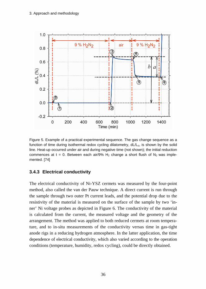
Dilatometry is a suitable technique for obtaining highly precise measurements of dimensional changes in solids, melts, powders and pastes with negligible sample strain. An alumina push rod exerts a small force on the flat-ended sample and the dimensional changes from e.g. thermal expansion, chemical reactions or sinter-ing are monitored by a high precision linear transformer. A DIL 402 CD differ-ential dilatometer from Netzsch GmbH, Germany, with programmed tempera-ture and gas change histories was used in the work. The programmed gas change control enabled the use of three different gases and allowed identical test se-quences to be done for different materials. Figure 5 shows an example of a dila-tometry curve obtained and the data derived from a redox experiment. The de-gree of redox reversibility (DRR) is the fraction of re-oxidation strain recovered during the following re-reduction, defined as a/b. The cumulative redox strain (CRS) and DRR analysis was dealt with in papers I and III was based on the strain at the indicated numbered points (0–6 in the present figure) during redox cycling, for further details on the CRS and DRR analysis the reader can consult [74], [88].
3. Approach and methodology
36
Figure 5. Example of a practical experimental sequence. The gas change sequence as a function of time during isothermal redox cycling dilatometry, dL/Lo, is shown by the solid line. Heat-up occurred under air and during negative time (not shown); the initial reduction commences at t = 0. Between each air/9% H2 change a short flush of N2 was imple-mented. [74]
3.4.3 Electrical conductivity
The electrical conductivity of Ni-YSZ cermets was measured by the four-point method, also called the van der Pauw technique. A direct current is run through the sample through two outer Pt current leads, and the potential drop due to the resistivity of the material is measured on the surface of the sample by two ‘in-ner’ Ni voltage probes as depicted in Figure 6. The conductivity of the material is calculated from the current, the measured voltage and the geometry of the arrangement. The method was applied to both reduced cermets at room tempera-ture, and to in-situ measurements of the conductivity versus time in gas-tight anode rigs in a reducing hydrogen atmosphere. In the latter application, the time dependence of electrical conductivity, which also varied according to the operation conditions (temperature, humidity, redox cycling), could be directly obtained.

3. Approach and methodology
37
Figure 6. Experimental set-up for direct current conductivity measurements.
3.4.4 Thermogravimetric analysis (TGA)
Thermogravimetric analysis (TGA) is performed on samples to determine changes in weight in relation to variations in temperature or in the chemical en-vironment. This analysis relies on a high degree of precision in three measure-ments: weight, temperature, and temperature change. TGA is commonly em-ployed in research and testing to gauge different characteristics of materials such as phase changes, transition temperatures and the stability of compounds. In the present context, the TGA was used to measure the reaction kinetics during high temperature reduction of NiO–YSZ and re-oxidation of Ni–YSZ in different conditions. A thermobalance STA 409 CD from Netzsch GmbH, Germany, was used in the measurements. The instrument was equipped with programmable temperature and gas change sequences. Different combinations of reduction and re-oxidation temperatures were applied in conjunction with the related dilatometry measurements.
3.4.5 Impulse Excitation Technique (IET)
The impulse excitation technique is a non-destructive material test method that uses the natural resonant frequency, dimensions and mass of a test-piece to de-termine the Young's modulus, shear modulus, Poisson's ratio and specific damp-ing. The dimensions and mass of the test-piece can be easily measured. The fun-damental resonant frequency of vibration is determined by gently tapping the test-piece and analysing the vibration by a microphone or laser vibrometer. The

3. Approach and methodology
38
sample is brought to vibration in a flexural or torsional mode by mechanical excitation using an automated tapping device. The Young’s modulus is calcu-lated from the fundamental resonant frequency and the dimensional data by ASTM standards. The RFDA System 23 from IMCE NV., Belgium, was used for the measurements. The Young’s modulus and specific damping were deter-mined for a range of different Ni–YSZ composites depending on temperature, porosity and redox cycling.
3.4.6 Porosimetry
The porosity of the composites is an important design parameter. Two different techniques were used to determine the porosity of the samples: the geometrical determination of total porosity and mercury intrusion porosimetry for open po-rosity. For the geometrical determination, the theoretical density (TD) of the samples was calculated from the known solids composition. By measuring the geometry (volume) and the mass of the samples, the total porosity of the samples could be calculated. Secondly, porosimeter Micromeritics AutoPore IV, Model 9510, Norcross GA, USA, was used for a smaller amount of small samples for determining the open porosity (and pore size distribution) of samples. This method is based on high-pressure intrusion of mercury into the porous sample; the volume of mercury intruded is then compared to the applied pressure.
3.4.7 X-ray diffraction (XRD)
X-ray diffraction is a non-destructive analytical technique that reveals informa-tion about the crystallographic structure, chemical composition, and physical properties of materials and thin films. It is based on observing the scattered in-tensity of an X-ray beam hitting a sample as a function of incident and scattered angle, polarisation, and wavelength or energy. Powder XRD is based on the elastic scattering of X-rays according to Bragg’s diffraction law. A STOE Theta/Theta diffractometer, using Ni-filtered Cu Ka radiation, STOE & Cie GmbH, Germany, was applied to examine the crystal structure of NiO powder as a function of temperature, and the composition of different doped NiO powder variants.
3. Approach and methodology
39
3.4.8 Particle size analysis
The knowledge of the particle size distribution (PSD) of raw materials, milled powders and particles dispersed in fluid is instrumental in making high-quality slurries for e.g. tape casting. There are a variety of techniques to measure the PSD; a method based on laser diffraction was used in this work. The PSD is determined based on an analysis of the diffracted light produced when a laser beam passes through a dispersion of particles in a liquid when the refractive indices of the species present are also known. A Laser Diffraction Particle Size Analyzer LS 13 320 from Beckman Coulter, USA, was used for this purpose in the ceramic processing of the powders and slurries.
3.4.9 Rheology
Rheology is the study of the flow of matter. This mainly involves liquids but also soft solids or solids at high temperature. The properties of the final ceramic product are highly dependent on the quality of the slurry; any unintentional het-erogeneities or defects introduced in the fabrication process persist in the final sintered component. The formability of the slurry depends on the rheological properties of the suspension and the properties must be tailored for the specific forming method used; the stability of the suspension can also be inferred from a rheological characterisation. The critical parameters of interest include the ap-parent viscosity (η), the yield stress under shear and compression, and the vis-coelastic properties, i.e., the loss modulus (G’’) and elastic modulus (G’) of the system. Typical shear-thinning behaviour of the tape casting slurries was moni-tored by measuring viscosity with increasing and decreasing shear rates along the ceramic processing line. Rheometer HAAKE Rheo Stress 600, Thermo Sci-entific (previously Thermo Electron), Germany, was used.
3.4.10 Scanning Electron Microscopy (SEM)
In the scanning electron microscope (SEM), the images of the sample surface are created by scanning it with a high-energy beam of electrons in a raster scan pat-tern. The electrons interact with the atoms that make up the sample and produce signals; these signals contain information about the sample's surface microstruc-ture, topography and composition. The types of signals produced by an SEM include secondary electrons, back scattered primary electrons (BSE) and charac-
3. Approach and methodology
40
teristic x-rays. The secondary electrons yield accurate images of the material, whereas the backscattered electrons show resolution between the different ele-ments present in the sample. The characteristic x-rays make it possible to do an energy dispersive spectroscopy (EDS) of the sample in order to obtain informa-tion on the elements in the sample. Additionally, there are different image analy-sis applications to do the statistical quantitative image analysis (QIA) of the microstructural features, provided that there is sufficient contrast between them. The different electron microscopes utilised in the present work include a JEOL low vacuum SEM, a Zeiss Supra 35 with a field emission gun, Gemini optics system, a lateral SE detector (Everhart–Thornley) and an inlens SE detector, and a Hitachi TM1000 tabletop SEM. With the Zeiss Supra, secondary electron (SE) imaging was done using both the lateral and the Inlens SE detector and low ac-celeration voltage. The low voltage operation with the inlens detector makes it possible to obtain the charge contrast in the image as well as information on the percolating and non-percolating fractions of Ni in the Ni–YSZ cermet. SEM was carried out to investigate the microstructures of as-sintered, reduced and re-oxidised composites.
3.4.11 Electrochemical Impedance Spectroscopy (EIS)
Electrochemical Impedance Spectroscopy (EIS) is an experimental method of characterizing electrochemical systems. This technique measures the impedance of a system over a range of frequencies as a response to a small alternating cur-rent (AC) perturbation. The frequency response of the system, including the energy storage and dissipation properties, is interpreted through modelling and analysis using an equivalent electric circuit. It is an important tool for investigat-ing the characteristic behaviour of electrochemical systems in terms of their ohmic and polarisation resistance, time constants in different conditions and changes in them over time. In this work, EIS was used for the analysis of sym-metric anode cells in the configuration Ni–YSZ (thin anode) – YSZ (thick elec-trolyte) – Ni–YSZ (thin anode) as shown in Figure 7. The degradation of the anode performance over time and the microstructural changes in the cermet due to redox cycling were analysed by measuring and analysing the impedance spec-tra over time during the testing. The impedance measurements were performed at open circuit voltage (OCV) using a Solartron SI1260 impedance/gain phase analyser, with 24 mV amplitude, in the frequency range of 0.05 Hz to 1 MHz.

3. Approach and methodology
41
Figure 7. Schematic of the electrochemical set-up for symmetric cell testing [89].
4. Ceramic processing of solid oxide fuel cells
42
4. Ceramic processing of solid oxide fuel cells The microstructure and homogeneity of the Ni–YSZ composites are crucial fac-tors in terms of their behaviour. Therefore, the manufacturing methods used in the production of such composites are of great importance and can significantly influence the characteristics of the anode support. Wet ceramic processing routes are very common in the preparation. The role of the methods and ceramic proc-essing steps used in the preparation is central to the outcome of the present work. Detailed information on the raw materials, processing steps and characterisation during the processing is, however, not revealed in this thesis. This is due to the proprietary nature of this information. Only information relevant for the under-standing of the investigated processes is therefore given in this chapter. Beyond the general treatment presented in the following sections, the interested reader can consult the available textbooks and review articles on ceramic processing and sintering [89], [90], [91], [92], or [93], [94], [95] on issues more specifically related to the materials and manufacturing of SOFC
4.1 Materials and microstructure
Two of the main development goals for solid oxide fuel cells are to reduce the manufacturing cost and improve their durability. While both of these aims are promoted by reducing the operating temperature, it is not generally true regard-ing cell performance. One way of reducing the manufacturing cost involves in-troducing cheaper alternatives for construction materials as long as their thermal matching is retained. In order for the ionic conductivity of the electrolyte (area-specific resistance) to remain the same or decrease, both its thickness and resis-tivity have to be minimised. Beyond the standard SOFC materials, new alterna-tives are sought. For improved ionic conduction in the electrolyte, the alterna-

4. Ceramic processing of solid oxide fuel cells
43
tives include scandia-stabilised zirconia and ceria. For enhanced cathode per-formance at decreasing temperatures, single phase cathodes of mixed ionic and electronic conductors like the perovskites LSCF and LSC combined with a in-terdiffusion barrier layer in the electrolyte interface are being investigated. On the anode side, the performance of the Ni–YSZ is still to be surpassed, at stack level, by fully ceramic or other novel compositions. Taking a typical LSM/LSCF – YSZ – Ni–YSZ ASE SOFC, a great deal can be done by microstructural optimisation through processing. The electrode reac-tions take place at the three-phase boundary (in a mixed ionic electronic conduc-tor, this boundary is extended), so that a fine microstructure will enhance the reaction rate. Sufficient porosity must be present to allow the arrival of the gase-ous reactants to the reaction site and to permit the removal of the reaction prod-ucts. The electrolyte should be dense, as thin as possible and have a good and stable adherence to both electrodes. In the anode, the nickel phase must be per-colating for current collection and at the same time, it must be interlocked by the ceramic phase to prevent inordinate performance loss (in the polarisation resis-tance) due to Ni particle growth. The anode support has slightly more free vari-ables since high electrochemical performance is not required – the internal re-forming of methane is of interest but this function does not necessitate a high three-phase boundary length, although a high surface area would be beneficial. The anode support might be slightly more porous in comparison to the anode in suppressing gas diffusion related losses. And, finally, the anode support should be dimensionally and structurally redox stable – a question closely related to both the composition and the microstructure.
4.2 Ceramic processing
The ceramic processing route cell could be divided into powder processing, the colloidal processing of suspensions, the shaping and joining of components, the removal of the solvent phase and sintering/firing to obtain the final densified microstructure. In the present context, the expression “ceramic processing” is used to refer to all five steps. Commercially available raw powders of NiO and YSZ were used. These are supplied as agglomerated granules that need to be milled down to the desired particle size distributions (PSD). This was done by ball milling in a colloidal suspension, leading to a good mixing of the compo-nents. In some cases, further pre-treatment of the raw powders was required. These treatments included dry and wet planetary milling of the raw powders to

4. Ceramic processing of solid oxide fuel cells
44
modify the PSD, doping the powders with secondary oxides, and calcinating the raw powders, milled raw powders and doped powders. In all stages of powder processing the progress was monitored by measuring the PSD. With the doped powder variants, SEM / FIB SEM investigations and zeta potential measure-ments were also carried out.
The term colloidal is normally used to describe particles that possess at least one dimension in the size range 10-3 – 1 μm [92]. Even if the actual PSD of the particles processed in the present work exceed the size of 1 micron, the term “colloidal processing” is used to cover the wet ceramic processing part of manu-facturing. The powders, solvent and dispersants are inserted together with the ceramic balls into the slurry container. The solvent constitutes the wet chemistry base in the suspension. The stability of the suspension depends on the degree of flocculation/de-flocculation of the particles. This depends on the balance of various interparticle forces, including van der Waals, electrostatic, steric and depletion, and the total interparticle potential energy. The van der Waals forces are long-range and always attractive among similar particles. Electrostatic forces can be controlled in aqueous solutions by generating like-charges of sufficient magnitude on the surfaces of the suspended ceramic particles. In steric stabilisa-tion, organic molecules or polymers are adsorbed on the surfaces of the ceramic particles to induce steric repulsion and thus prevent flocculation. The steric hin-drance by the adsorbed polymer must be of sufficient thickness so that the van der Waals attraction and bridging flocculation are overcome. Depletion (or struc-tural) forces and stabilisation can be produced by adding small nonadsorbing species to the solution. By controlling these forces through additives and dis-persants, the suspension can be tailored for the selected forming method. Differ-ent types of flow behaviour can be observed under steady shear. Newtonian be-haviour is the simplest flow response, where viscosity is independent of the shear rate. Pseudoplastic or shear-thinning behaviour occurs when the viscosity decreases with shear rate, often accompanied by an initial yield stress. If the flow curve is linear above the yield stress, the system is referred to as Bingham plastic. Finally, dilatant or shear-thickening behaviour occurs when the viscosity increases with the shear rate.
After ball milling, a binder was added to the slurry so that the viscosity could be adjusted. There are several forming techniques that can be used for thin layer electrolyte solid oxide fuel cells [96], including tape casting, slip casting, spray-ing and screen printing [7], [95]. For the anode support green tapes, tape casting was applied, with the doctor blades adjusted so that green tapes with various

4. Ceramic processing of solid oxide fuel cells
45
thicknesses were obtained. After the casting step, the tape is generally consoli-dated into a green tape ready for further processing by fluid removal due to evaporation. Most of the experiments were carried out using samples that were directly cut out from the green tape and sintered. The anode support, anode and the electrolyte were produced separately, and were joined together by procedures such as screen printing or lamination. The final part of the ceramic processing was the high temperature sintering of the green samples, tapes or half cells. This kind of sintering is a two-step process where the organics are first burned out at a lower temperature and then sintered at a high temperature. The green samples were sintered at 1,200–1,400oC. The sintering proceeds as a thermally activated minimisation process of the surface area where initially (ideally) spherical ce-ramic particles start increasing their contact area. The necking between particles occurs in the contact areas and the material is removed from the initial point contact between the spheres. The process leads to densification, that is, the cen-tre points of the particles move closer to one other and the bulk sample shrinks as a function of time. The sintering activity depends on the size distribution of the ceramic particles; small particles with a high surface area are more reactive to sintering than large particles. Sintering can be facilitated by dopants that in-crease the ionic mobility; on the other hand, some additives will slow down the sintering process or increase the activation temperature for sintering. The differ-ent mass transport mechanisms during sintering are evaporation–condensation, volume (bulk) diffusion and surface migration. Microstructural analysis by elec-tron microscopy of the sintered structure is an important tool when developing the optimised component.

5. Electrical and microstructural degradation of Ni–YSZ
46
5. Electrical and microstructural degradation of Ni–YSZ
5.1 Normal operation
Besides the thermomechanical degradation and failure due to the redox cycling of Ni-based ASE cells, the electrical and electrochemical effects are of great interest, in both normal and abnormal conditions. The electrical conductivity of a Ni–YSZ cermet is known to degrade with time at high temperatures due to sintering of Ni; fine nickel grains are known to grow in size in both microcom-posites of Ni-YSZ [97], [98] and in fine particle nanocatalysis [99], [100]. The mobility of the micron-sized Ni embedded in the porous YSZ backbone is de-pendent on operating conditions and increases with increasing temperature. The process tends to lower the total surface energy of the system; the mass transport may take place through the bulk material, grain boundaries, by surface migra-tion, or in the gas phase through evaporation and condensation. In this work, the growth of Ni grains that occurs at the expense of the smallest grains is referred to as the sintering of nickel, irrespective of the mass transport mechanism. The growth is more pronounced when the initial grains are smaller (or actually, when the initial surface area is larger) and the higher the temperature. Both experimen-tally and in DFT calculations, humidity has been shown to boost Ni sintering through increased surface diffusivity of the Ni2–OH species formed. The forma-tion of the Ni hydroxide is favoured by a high steam to hydrogen ratio as pointed out by Sehested [99], [100]. The sintering of the Ni network may result in per-formance degradation through a loss of the electrical conductivity of the anode support (current collection). In addition, the electrochemical performance of the anode can be affected when the active three-phase boundary is reduced. The sintering of Ni also appears as one of the mechanisms behind redox instability [48], [74].

5. Electrical and microstructural degradation of Ni–YSZ
47
The ceramic-metal Ni–YSZ interface is formed upon the reduction of the as-sintered composite. The energetics of the interface can be characterised by the work needed to separate two bonded surfaces. This is expressed through the Dupré equation [101], [102]
22 ,''' ZrOmZrOmsepW γσσ −+= , (4)
where σ’m and σ’ZrO2 stand for cleaved metal and ceramic surface Gibbs free energies and γ’m,ZrO2 is the interface energy, all per surface area. The actual work of separation needed to cleave the interface is more than that given by Eq. (4), since there are dissipative processes and the cleaved surfaces do not have time to reach a new equilibrium in contact with ambient gas. Taking the reversible changes into account, Finnis has defined the work of adhesion as [101]
22 ,ZrOmZrOmadhW γσσ −+= . (5)
and now the equilibration of the ceramic and metal surfaces takes place. The sintering of Ni in porous cermets changes the ability of the Ni network to
percolate and a degradation of conductivity can be observed. The sintering gen-erally depends on time t and particle radius R according to
npn rtArx //1)( −⋅⋅= , (6)
where the exponents n and p vary depending on which sintering mechanism is dominant, x is the width of the necking, and A is a constant containing the sur-face tension and the relevant diffusion coefficient [103]. A ceramic-metal com-posite produced by wet ball milling contains particles with a size distribution typically ranging from a few tens of nanometres up to a few micrometers. The sintering is thus most pronounced in the finest fraction of the microstructure, which tends to disappear. The larger particles grow at the expense of the smaller ones; this thermodynamically-driven spontaneous process is generally known as Ostwald ripening. The actual mass transport in the system at hand may take place either through surface diffusion or via the gas phase. A possible sintering mechanism in the gas phase may occur due to the fact that the equilibrium va-pour pressure over a spherically curved surface with a radius R is greater than that which occurs over a flat surface by the ratio [104]
⎟⎟⎠
⎞⎜⎜⎝
⎛ Ω=
∞ RTkpp oR γ2
exp , (7)

5. Electrical and microstructural degradation of Ni–YSZ
48
where Ωo is the atomic or molecular volume, γ the surface tension and k the Bolzmann’s constant. When a small particle is in the vicinity of a larger particle, a diffusive flow of matter can develop towards the larger particle because of the concentration gradient caused by the higher equilibrium vapour pressure above the smaller particle.
The stability of the metal-ceramic interface affects the sintering and the long-term stability of the composite. The wetting of liquid metal droplets on ceramic substrates can be investigated using the sessile drop technique to study the strength of the interfacial interaction, by measuring the contact angle θ between the substrate and the metal droplet [105], [106]. The work of adhesion Wadh and the contact angle are correlated through the Young-Dupré equation
)cos1( θσ += LmadhW . (8)
Equation (8) states that the contact angle is determined by the adhesion energy between the solid and the liquid phases, and the surface energy of the liquid phase. Most metals in contact with refractory ceramics show non-wetting contact angles (θ > 90o), for example, contact angles of liquid Ni with several oxides is in excess of 100o. Tsoga [106] and Mantzouris [107] reported decreasing wetting angles when the stabilised zirconia substrate was doped with TiO2. For nano-composites of Ni–YSZ, improved mechanical stability and hardness have been reported due to good interfacial adhesion. This adhesion is weakened when the particle size increases; in fact, in microcomposites the enforcing effect from the metal cannot be observed. It has been proposed that the relatively high degree of epitaxy between Ni and TZP in nanocomposites is due to very good lattice matching between ZrO2 and nickel (in the preferred crystal orientation), and the evaporation-condensation grain growth mechanism operating in metallic nanoparticles during sintering [32]. According to this hypothesis, when moving to larger grain sizes, the change in sintering mechanism takes place and the exis-tence of less favourable interface orientations decreases the work of separation.
Electrical conductivity is a good in-situ measure to monitor and quantify the microstructural changes in the cermet; the sintering of Ni leads to the loss of percolation and degrades the electrical conductivity. The degradation is initially fast and slows down to finally reach a plateau characteristic of the cermet micro-structure and the operating conditions. This type of behaviour is qualitatively shown in [108], [49], and results when applying Eq. (6). The extent to which sintering degrades the initial conductivity depends on the temperature and hu-midity of operation, but also on the microstructure and composition of the cer-

5. Electrical and microstructural degradation of Ni–YSZ
49
met. Electrical DC conductivity measurements and selected scanning electron microscopy carried out in the work are reported in section 6.6, and will be dis-cussed in more detail in a forthcoming paper [109].
5.2 Effects from redox cycling
The thermomechanical degradation of the Ni–YSZ cermet, the detachment of the anode/electrolyte interface and the failure of the electrolyte typically result in a loss of electrochemical reaction sites, ionic conduction paths and fuel. Generally, this can be observed as a drop in the performance of the cell. Grahl-Madsen et al. [110] reported that the DC electrical conductivity of Ni–YSZ composites with coarse Ni increased from 500 to 1,000 S/cm upon a redox cycle at 850oC (the in-plane conductivity also given at 850oC). Young et al. [111] report an increase in the DC electrical conductivity of Ni–YSZ cermets as a function of redox cycles at 800oC, while the conductivity in an anode electrode, presumably having another microstructure, decreased. The electrochemical performance of the anode improved when redox cycling occurred at 800oC for both the serial and polarisation resistance, as long as the ceramic backbone and the electrolyte remained intact [111].
DC conductivity measurements during low and intermediate temperature re-dox cycling were made. The changes in the composite microstructure were ex-amined by a scanning electron microscope. The results are summarised in sec-tion 6.6, and will be discussed in more detail in a forthcoming paper [112].

6. Results and discussion
50
6. Results and discussion
6.1 Dimensional behaviour of Ni–YSZ cermets (Publication I)
An improvement of the structural and dimensional stability of the Ni–YSZ is a prerequisite for a redox stable SOFC and was therefore the main goal of this work. Dilatometry was the key technique to monitor such behaviour. In the work reported in Publication I [74], Ni–YSZ cermets were tested in redox cycling dilatometry for a wide range of operation conditions. The main parameters that varied were temperature and humidity. The dependencies of the dimensional behaviour of the cermet were obtained both during reduction and re-oxidation. The four main observations reported in the paper were: i) the expansion of the composite on re-oxidation increases when the temperature of the initial reduc-tion is increased, ii) the expansion of the composite on re-oxidation increases when the initial reduction conditions remain unchanged and the temperature of the re-oxidation is increased, and iii) the effect of humidity, which increases the redox strain at a high temperature (850oC), whereas iv) no negative effect from humidity was observed at a low-temperature re-oxidation (600oC).
During the initial reduction at a low temperature (600oC), a contraction of about 0.08% and recovery towards the initial length was observed. At intermedi-ate temperatures (800–850oC), little or no dimensional change in reduction was noted. During high temperature reduction (1,000oC), on the other hand, a shrink-age of 0.05% occurred; at still higher temperatures, the cermet showed signifi-cant shrinkage in reduction. These differences were explained by different tem-perature-dependent relaxation in the Ni/NiO phase leading to strain recovery at the lowest temperature, and to permanent length change through sintering / plas-ticity in the YSZ at high temperatures.

6. Results and discussion
51
The cumulative redox strain after three redox cycles in dry conditions in-creased from 0.25 to 3.2% dL/Lo, when the isothermal redox cycling temperature was increased from 600 to 1,000oC, as shown in Figure 8. Humidity was noted to deteriorate redox stability at high temperatures (roughly 850oC or higher); CRS after three redox cycles at 850oC and in humid conditions (6% steam and a very high p(H2O)/p(H2)) was clearly more than in dry conditions at the same temperature, and close to the CRS at 1000oC in dry conditions. Humidity showed no visible effect on redox strain at 600oC. The degree of reversibility of the redox strain (DRR) decreased with increasing temperature; DRR also dropped at 850oC in the presence of humidity. The rate of dimensional change during oxidation decreased when the p(O2) decreased during the oxidation phase, indicating a kinetic effect depending on p(O2).
Figure 8. Relative length change of Ni–YSZ composites as a function of time during three isothermal re-oxidation cycles under dry conditions at different temperatures. The initial reduction takes place at t = 0, and the dL scale shows the relative length change from the hot as-sintered state prior to the initial reduction. [74]
Furthermore, Ni particle growth was confirmed to deteriorate redox stability by increasing the redox strain on re-oxidation. Of two similar samples, one was reduced for 5.5 h at 800oC and the second one for 4.5 h at 1,100oC. The sample reduced at 1,100oC showed about twice the amount of redox strain when both samples were re-oxidised at 800oC, Figure 9.

6. Results and discussion
52
As shown in Figure 10, the temperature of re-oxidation is an important pa-rameter that affects the cumulative redox strain. In a set of samples pre-reduced for 3 h at 1,000oC, the re-oxidation strain was about 1% when re-oxidation took place at 850 or 1,000oC, while it was 0.31–0.36% when the re-oxidation was carried out at 600 or 750oC. In the investigated data set, effect from the tempera-ture of re-oxidation on redox strain was thus more significant than the tempera-ture of the initial reduction.
Figure 9. Relative length change vs. time caused by the re-oxidation of reduced Ni–YSZ composites; this shows the effect of the initial reduction temperature on redox strain. The solid line is for a cycle where both the reduction and re-oxidation were done at 800°C. The dashed line shows the reduction at 1,100°C and the redox at 800°C. [74]

6. Results and discussion
53
Figure 10. Relative length change as a function of time for Ni–YSZ cermets all pre-reduced at 1,000°C and re-oxidised, at temperatures of 600, 750, 850, and 1000°C. [74]
6.2 Mechanical properties (Publication II)
Re-oxidising the cermets at a high temperature typically leads to thermome-chanical failure. Therefore, investigating the mechanical degradation caused by redox cycling was of interest. In the work leading to Publication II [113], Ni–YSZ and NiO–YSZ composites were tested for elastic properties at room tem-perature and for viscoelastic properties within the entire temperature range of interest in both the oxidised and the reduced state. The Impulse Excitation Tech-nique was used for the measurements.
A number of different samples were produced by ceramic processing, includ-ing a typical baseline cermet and composites with modified microstructures and compositions. The total porosities and dimensions of the thin plate samples were determined geometrically. The measured Young’s moduli of the composites show a linear dependence on porosity. Linear correlations were fitted to the elas-tic property data with porosities in the oxidised state ranging from 9 to 38% and from 31 to 52% in the reduced state; the data point for a fully dense composite was fixed by using the linear rule of mixtures and knowing the composition of the composite as well as the Young’s moduli of the constituents. The data meas-ured for Young’s modulus vs. porosity on as-sintered and reduced composites are shown in Figures 11 and 12, respectively.

6. Results and discussion
54
The dependencies of the Young’s modulus and the specific damping of the baseline composite as a function of temperature were determined in both the oxidised and reduced states. In the oxidised state, a reversible steep increase was discovered to take place in Young’s modulus between about 200 and 260oC, with a peak at 250oC (the Néel temperature of NiO). Above 260oC, Young’s modulus decreased in a largely linear manner with temperature. The specific damping showed a peak around 180oC and increased again above 1000oC, as shown in Figure 13.
Figure 11. Young’s modulus of as-sintered NiO–YSZ composites as a function of total porosity with a linear correlation fitted to the data (the black line) and other correlations reported in the literature (the grey lines). The half cell data are consistent with NiO–YSZ composites. [113]

6. Results and discussion
55
Figure 12. Young’s modulus of reduced Ni–YSZ composites as a function of total porosity including a linear correlation fitted to the data. The half cell data in the reduced state are consistent with the Ni–YSZ cermets. [113]
Figure 13. Young’s modulus and specific damping as a function of temperature during heat-up and cool-down of an as-sintered NiO–YSZ composite. [113]

6. Results and discussion
56
The elastic properties in the reduced state were measured for samples pre-reduced either at a low (600oC) or a high (1,000oC) temperature. The Ni–YSZ composite showed a linear decrease in Young’s modulus with temperature up to 1,000oC and little effect from the initial reduction temperature. Specific damping of the composite determined from the fundamental flexural resonant frequency showed only minor (if any) differences between samples with different reduction treatments when measured at room temperature. High temperature tests showed (i) a peak in specific damping at 160–180oC, (ii) an increase in the damping of the high-temperature-reduced Ni–YSZ cermet above roughly 1,000oC, (iii) an increase in damping starting at lower temperatures in the reduced cermets in comparison to the oxidised state, and (iv) the dependence of the damping in the Ni–YSZ composite on microstructure, where the fine microstructure after a low temperature reduction results in a higher specific damping. The damping de-creases at higher temperatures; this was attributed to microstructural changes originating from Ni sintering. The measured data on a cermet reduced at 600oC and heated up under reducing conditions to 1,000oC with subsequent cooling are shown in Figure 14. This shows clear changes in specific damping due to Ni sintering during the test.
Figure 14. Young’s modulus and specific damping as a function of temperature during heat-up and cool-down of a Ni–YSZ composite sample pre-reduced at 600oC and tested in a reducing atmosphere. Damping is shown to be a sensitive function of the microstruc-ture with higher damping related to finer microstructure. [113]

6. Results and discussion
57
To investigate the degradation of the mechanical properties due to redox cycling, an experimental series with repeated reductions and re-oxidations of up to eight redox cycles was carried out. The series was done at isothermal temperatures of 750–790oC with Young’s modulus measured at room temperature between the cycles. A decrease in Young’s modulus was observed on cyclic re-oxidations and the loss of stiffness could be linearly correlated with the cumulative redox strain measured from the sample length change. The mechanical degradation due to structural damage started at about 0.5% redox strain, whereas a macroscopic loss of integrity of the samples resulted when the strain exceeded approximately 2.5%. In the discussion it was concluded that the porous composite can be viewed as a complex three-dimensional structure composed of a large number of Hookean springs or anelastic spring-dashpot elements connected in series and in parallel. The bulk stiffness of a sample results from the integral effect of these elastic elements. When the structure suffers from microscopic or macroscopic damage, in this case by redox cycling, it is equal to removing elastic elements from the bulk structure; as a result, a decrease in Young’s modulus is observed. In macroscopic terms, the cumulative redox strain is thus a measure of the irre-versible dimensional change (non-elastic strain) in the composite due to redox cycling. The CRS was more or less linearly related to the microscopic and mac-roscopic damage that occurred in the composite and which manifested itself as loss of stiffness. An isotropic continuum damage model for elastic degradation was expressed in a simple form as
oEE ⋅−= )1( ω (9)
where E is the elastic modulus, ω the damage variable (with values from 0 to 1), and Eo the initial modulus. Fitting a parameter )(CRSω to the present redox degradation data yields the damage variable shown in (10); it is also depicted graphically in Figure 15.
⎪⎩
⎪⎨
⎧
≥<≤−⋅
<=
0292.0,10292.00046.0,1879.0655.40
0046.0,0)(
CRSCRSCRS
CRSCRSω (10)

6. Results and discussion
58
Figure 15. Mechanical degradation in terms of the relative loss of elastic modulus of NiO–YSZ composites during redox cycling, as a function of CRS (the cumulative sample length change caused by the redox cycling). [113]
6.3 The effect of microstructure on redox stability (Publication III)
The ceramic processing developments resulted in a number of different compos-ite variants, altered in microstructure and composition compared to the baseline cermet. Some of the Ni–YSZ cermet variants were tested in dilatometry and thermogravimetry for dimensional stability during redox cycling under isother-mal conditions at 850oC. These results were reported in Publication III [89]. The composites showed very different dimensional behaviour depending on the mi-crostructure of the cermets. The main conclusion of these investigations was that the dimensional stability was very dependent on the microstructure; the samples with high porosity were found to be the most stable.
The results showed that, first, upon the initial reduction, the baseline cermet showed very little dimensional change at 850oC, whereas the modified cermets with a higher total porosity exhibited a contraction of about 0.1–0.3% after an induction period of approximately 20 min. It was suggested that this difference was owed to the distinct relaxation behaviour of the Ni/NiO phase in the two composites. The reduction of the baseline sample was considerably faster (about 20 min) than that of the modified composite, for which the full reduction took several hours. This means that even though the modified sample is more porous

6. Results and discussion
59
than the baseline sample, the local microstructure in the NiO phase is different enough to cause slower reduction kinetics. Stress relaxation in the partially re-duced Ni/NiO phase is much slower than in fully reduced Ni; therefore, the re-duction shrinkage of Ni was partially transformed into the ceramic backbone in the modified cermets and a bulk contraction was observed during reduction. Second, upon re-oxidation, both the baseline and the modified samples started to show redox strain after about 5 min from the change of the atmosphere into oxi-dising. This corresponds to about 0.4–0.5 in terms of DoO in the baseline sam-ple. In the modified sample, the rate of the length change was slower than for the baseline sample, and the onset of expansion took place at a higher DoO, about 0.8. The measured re-oxidation kinetics of the modified sample was faster than for the baseline sample, possibly due to the good access of air into the cermet through the high open porosity of the modified sample.
The dimensional behaviour of the different cermets during three redox cycles is summarised in Figure 16. The CRS increased more than 20 times the as-sintered porosity decreased from 34 to 9%. This was related to the cermet poros-ity, which acted as spare volume, accommodating the expansion of the Ni/NiO phase during the re-oxidation. The most stable cermets showed CRS not exceed-ing 0.1% during three redox cycles, thus reaching the target set for dimensional stability of the supporting cermets. They also had a degree of redox reversibility, DRR, of near unity during the three redox cycles and were macroscopically in-tact after the experiments. The effect of the Ni doping on the redox stability of the cermets was also discussed but no clear conclusions on the separate effect of dopants could be made; clearly, the use of dopants resulted in the variation of the as-sintered porosity of the composites. As was observed from the CRS and DRR variations of the undoped samples, this porosity variation directly affects the dimensional behaviour due to the different microstructures. If the microstruc-tures of the composites being compared had been the same, the effect of the dopants on the actual redox behaviour of the Ni/NiO phase would be easier to assess. In any case, the use of dopants was identified as a potential way of tailor-ing cermets and improving the redox stability; more conclusive statements in this area, however, require additional work.

6. Results and discussion
60
Figure 16. Cumulative redox strain (CRS) as a function of time from the initial reduction during three isothermal redox cycles of different Ni-YSZ cermets at 850oC. The zero-point on the CRS scale corresponds to the sample length prior to the initial reduction at the same nominal temperature. [89]
Electrochemical testing of symmetric anode cells was carried out. These experi-ments on Ni–ScYSZ symmetric thick electrolyte cells showed that while iso-thermal redox cycling at 850oC did not significantly alter the electrode perform-ance, redox cycling of another cell with similar initial reduction treatment showed a 60% reduction in the polarisation resistance value when redox cycled at 650oC. The improvement in the electrochemical performance of the anode on low temperature redox cycling was attributed to the change in the microstructure of the electrode due to the redox cycle. Smaller Ni grains were observed and no damage was noted in the ceramic structure for the sample redox cycled at 650oC. The effect of redox cycling on the polarisation resistance is illustrated in Figure 17.

6. Results and discussion
61
Figure 17. Nyquist plots of representative impedance data recorded at OCV in 97% H2 +3% H2O: at 850, 750 and 650oC before re-oxidation and 10.2 h after the start of the re-reduction stage (test A, top); at 850oC before re-oxidation, at 850oC, 10.2 h after the start of the re-reduction stage and at 650oC after the redox cycle (test B, bottom). [89]
6.4 The kinetics of reduction and re-oxidation (Publication IV)
The driving force behind the redox problematic arises from the chemical reac-tion between Ni and NiO and the related strain. The chemical strain generation rate is directly proportional to the extent of the reaction. For practical applica-tions, it is important to know the kinetics of reactions in different conditions. To investigate these aspects, porous NiO–YSZ and Ni–YSZ composites were inves-tigated for reduction and oxidation kinetics using TGA at different isothermal conditions. This work was reported in Publication IV [114].
According to the findings, which generally concurred with other published data, the reduction kinetics of baseline NiO–YSZ composites followed a linear trend with time, indicating an interface controlled reaction. The reaction rate changed when approaching full reduction at low temperatures (500–600oC) to-wards a logarithmic time dependency. The activation energy for reduction in the temperature range 500–750oC was determined to be 84.4 kJ/mol. It was also confirmed that humidifying the reducing gas (9% H2 and 91% N2) with 3%

6. Results and discussion
62
steam marginally slows down the reduction. The reduction kinetics was mod-elled using different correlations and the best fit was obtained using the Avrami equation:
)exp(1 mAtkDoO −=−= α , (11)
where, α is the degree of reaction (for reduction), kA is the Avrami rate constant and m the power in the time dependence. The Avrami power law exponent m was 1.97–1.98 at 850–1,000oC and 0.54–0.58 at 500–600oC, suggesting a change in the reaction mechanism. At the low temperatures of 500 and 600oC, the re-reduction subsequent to the first redox cycle was remarkably faster than the ini-tial reduction. This indicated that the low temperature redox cycle altered the microstructure of the composite. The reduction kinetics at different temperatures of the typical baseline NiO–YSZ composite is shown in Figure 18.
Figure 18. The degree of oxidation as a function of time from gas change into reducing during isothermal reduction at 1,000, 850, 750, 600 and 500°C of NiO–YSZ composite samples with a thickness of 0.6 mm. [114]
The re-oxidation of Ni–YSZ cermets pre-reduced at 1,000oC showed linear and rapid initial oxidation to DoO of about 10–20%. The initial stage was followed by parabolic kinetics as was expected for a diffusion controlled reaction. When approaching the full degree of oxidation, the reaction rate changed even further to become logarithmic; the lower the re-oxidation temperature, the faster this retardation commenced. The oxidation kinetics in the parabolic region was only slightly dependent on temperature, suggesting a contribution from gaseous mass

6. Results and discussion
63
transport in the porous cermet. Effective diffusivities in the cermets were deter-mined from the oxidation data. Linear, parabolic and logarithmic rate constants were fitted to the re-oxidation data in each kinetic domain at temperatures of 600–1000oC. The re-oxidation kinetics at different temperatures of the typical baseline Ni–YSZ composite pre-reduced at 1,000oC is shown in Figure 19.
Figure 19. Degree of oxidation as a function of time from the gas change into oxidising during isothermal re-oxidation at 1,000, 850, 750 and 600°C of pre-reduced Ni–YSZ composite samples with a thickness of 0.45 mm. [114]
For a combined analysis of the dimensional behaviour and the reaction kinetics of the cermets, additional measurements were done using TGA. These results were then combined with dilatometry tests run with identical gas change and temperature programmes. The combined dilatometry – TGA analysis showed a 10–15 min induction time after the gas change from oxidising to reducing, be-fore any dimensional change could be measured. At high temperatures, the re-duction was complete within the initial induction time and only a minor negative dimensional change (if any) resulted. At low temperatures, however, the reduc-tion process had not been completed within the induction time and continuing reduction resulted in a contraction in the composite, combined with a recovery towards the initial dimension. Upon re-oxidation, an induction period of about 5 min was observed after the atmosphere changed to oxidising and before the ex-pansion started. At high temperatures (1,000 and 850oC), the redox expansion largely followed the oxidation reaction with an increasing time lag from full DoO (full re-oxidation) to the maximum strain response when going from 1,000

6. Results and discussion
64
to 850oC. Decreasing the re-oxidation temperature to 750oC and further to 600oC resulted in (i) an increasing time lag between the chemical reaction rate and the dimensional response, (ii) a decrease in the maximum redox strain (CRSmax) due to the re-oxidation and (iii) a shifting of the point at which the CRSmax was reached to values of DoO before full oxidation.
There were clear visual differences in Ni–YSZ composites depending on the re-oxidation temperature. High-temperature oxidation resulted in green samples, while decreased re-oxidation temperatures produced darker green or even grey samples. BET measurements showed a slightly decreasing surface area in the differently coloured re-oxidised NiO–YSZ composites when the re-oxidising temperature was reduced. No effective new open porosity or surface area seems to be generated on the low-temperature re-oxidation of the composites; in fact, the data suggest a slightly opposite effect. In the discussion, the beneficial effect of improving the stability of Ni–YSZ composites during low temperature redox cycling was suggested to be caused by stress relaxation in the NiO phase.
6.5 The mechanisms of redox instability (Publication V)
Based on the experimental information described in the previous sections (Pub-lications I–IV) as well as data from available literature, a continuum mechanics model was developed to simulate the dimensional behaviour of NiO/Ni–YSZ composites during reduction–re-oxidation cycles at high temperatures. The model structure and results from the simulations were reported in Publication V [115].
The purpose of the model was to facilitate the discussion on the internal mechanisms and processes in the cermet that lead to redox instability. The model starts from the chemical strains that occur due to the Ni ↔ NiO phase change and takes into account different nonelastic strains to reduce the stresses gener-ated; Figure 20 shows the basic structure and processes of the model during re-duction and Figure 21 during re-oxidation.

6. Results and discussion
65
Figure 20. The basic structure of the model during reduction, where the bulk length change of the composite is given by the elastic + nonelastic strain in the YSZ phase, and the stress state is generated by the chemical strain in the Ni/NiO phase. [115]
Figure 21. The basic structure of the model during re-oxidation, where the bulk length change of the composite is given by the elastic + nonelastic strain in the YSZ phase, and the stress state is generated by the chemical strain in the Ni/NiO phase. [115]

6. Results and discussion
66
Creep models for Ni, NiO and YSZ were taken from literature and implemented to account for nonelastic strains, diffusional creep through both the bulk material and grain boundaries, power law creep for Ni, and grain boundary sliding (GBS) for YSZ. Additional nonelastic strains were produced in the simple semi-empirical models implemented for pseudoplasticity and/or microcracking of NiO and cracking of YSZ. Several semi-empirical correlations were incorporated to account for different known subprocesses, such as the grain/subgrain growth in Ni and NiO, particle coarsening (sintering) in the Ni phase and particle growth due to porosity build-up in the NiO grains during the re-oxidation process. The model treats the porous NiO/Ni–YSZ composite as an isotropic continuum in which the YSZ phase constitutes the stable ceramic backbone. Micron-sized NiO/Ni is embedded within the ceramic backbone as a percolating phase. The YSZ and NiO/Ni phases are connected to each other through a sub-micron-sized interface. The microstructure has been simplified to a continuum, where the stress and deformations are related to a single dimension. The simulations pro-ceeded as a time series. In the numerical time discretisation, the stress in the present time step was calculated and once this had been determined, the nonlin-ear strain contributions could be incremented in the following time step. The chemical strains create the stress state in the composite; the stress is equal in magnitude but opposite in direction for the YSZ and the Ni/NiO phases. The different strains leading to this equilibrium are depicted in Figure 22 during re-duction and Figure 23 during re-oxidation.

6. Results and discussion
67
Figure 22. Strains and stress during reduction of the NiO-YSZ composite. [115]
Figure 23. Strains and stress during the re-oxidation of the Ni-YSZ cermet. [115]

6. Results and discussion
68
Seven redox dilatometry experiments were simulated using the experimental reduction-oxidation kinetics data from similar TGA experiments. The experi-ments comprised four different reduction temperatures isothermally followed by re-oxidations, and three cases where the initial reduction was carried out at a high temperature and the re-oxidation temperature was lower. The continuum model reproduces the dimensional behaviour of the composites and generally concurs with the findings of this work. The main stress relaxation processes were identified in each stage of redox cycling. During the initial reduction, creep rates in the Ni/NiO phase determine whether or not the composite contracts. Slower kinetics of reduction typically leads to a contraction of the composite. Upon re-oxidation and during the early stages of the oxidation process, metallic Ni can still creep and thus relax the stress. Later in the oxidation process and an increasing DoO, the creep rates are soon controlled by NiO and thus become significantly smaller.
The main results from the simulations were the following. The increase in the redox strain and the damage observed upon re-oxidation at high temperatures was accurately reproduced by the model. The increase in the permanent redox strain resulted from nonelastic strains in the YSZ phase. At 1,000oC, this strain came from YSZ creep (GBS) and microcracking of the YSZ, and at 850oC it mainly stemmed from fractures in the YSZ backbone. In the simulations, the loss of strain reversibility upon re-reduction of the re-oxidised composite was a direct result of the nonelastic strains produced in the YSZ phase. The mechanical degradation due to redox cycling observed in the composites is a result of the nonelastic damage created in the YSZ phase. In the discussion it was concluded that during the re-oxidation, the implementation of stress relaxation by pseudo-plasticity and microcracking in the NiO phase becomes instrumental in obtaining findings similar to the measured data. Figure 24 shows an example of a meas-ured redox strain curve together with the simulated redox strain (reduction at 1,000oC, re-oxidation at 600oC).
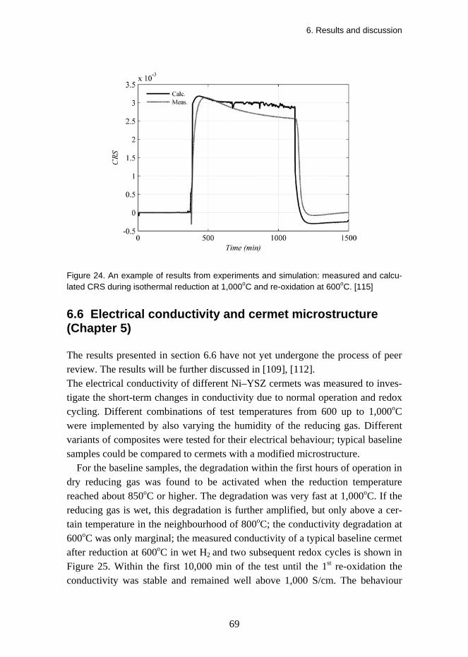
6. Results and discussion
69
Figure 24. An example of results from experiments and simulation: measured and calcu-lated CRS during isothermal reduction at 1,000oC and re-oxidation at 600oC. [115]
6.6 Electrical conductivity and cermet microstructure (Chapter 5)
The results presented in section 6.6 have not yet undergone the process of peer review. The results will be further discussed in [109], [112]. The electrical conductivity of different Ni–YSZ cermets was measured to inves-tigate the short-term changes in conductivity due to normal operation and redox cycling. Different combinations of test temperatures from 600 up to 1,000oC were implemented by also varying the humidity of the reducing gas. Different variants of composites were tested for their electrical behaviour; typical baseline samples could be compared to cermets with a modified microstructure.
For the baseline samples, the degradation within the first hours of operation in dry reducing gas was found to be activated when the reduction temperature reached about 850oC or higher. The degradation was very fast at 1,000oC. If the reducing gas is wet, this degradation is further amplified, but only above a cer-tain temperature in the neighbourhood of 800oC; the conductivity degradation at 600oC was only marginal; the measured conductivity of a typical baseline cermet after reduction at 600oC in wet H2 and two subsequent redox cycles is shown in Figure 25. Within the first 10,000 min of the test until the 1st re-oxidation the conductivity was stable and remained well above 1,000 S/cm. The behaviour

6. Results and discussion
70
was largely similar in dry conditions. (The results after the re-oxidation at 10,000 min will be discussed later). Results from a similar experiment at 850oC in a dry mixture of 40% H2 and 60% He are shown in Figure 26; the electrical degradation is remarkably faster during the initial reduction up to about 11,500 min (the effects of the subsequent redox cycling will again be discussed later). Varying the gas composition during the sintering test showed that the conductiv-ity degradation in dry gas was faster when hydrogen was diluted with He (40% H2, 60% He) compared to the case where H2 was diluted with Ar (40% H2, 60% Ar). When the experiment was carried out in wet gas (H2, steam, He or Ar), the cermet in the test with He-diluted hydrogen degraded slightly faster than in the test where H2 was diluted with Ar. The difference in terms of the diluting gas was less pronounced in wet conditions than in dry conditions.
The third example is shown in Figure 27, where isothermal reduction at 1,000oC in dry H2 was done for 28 hours. The degradation of conductivity was extremely fast in this case; the maximum conductivity achieved in the experi-ment was only about 765 S/cm. In fact, operation at 1,000oC in dry or at 850oC in wet conditions rapidly degrades the conductivity to about 400–500 S/cm. The degradation was attributed to sintering and the loss of percolation in the Ni phase, as was also verified by electron microscopy.
Figure 25. In-situ electrical conductivity based on a four-point DC measurement of the Ni–YSZ composite after an isothermal reduction in wet hydrogen at 600oC with two re-oxidations in air, together with the measured oxygen partial pressure.

6. Results and discussion
71
Figure 26. In-situ electrical conductivity based on a four-point DC measurement of the Ni–YSZ composite after an isothermal reduction in a dry mixture of 40 ml/min H2 – 60 ml/min He at 850oC, together with the measured oxygen partial pressure. Note that a redox cycle by air insertion is implemented at 11,800 min and the sample is re-reduced at 12,150 min.
Figure 27. In-situ electrical conductivity based on a four-point DC measurement of the Ni–YSZ composite after an isothermal reduction in dry hydrogen at 1,000oC, together with the measured oxygen partial pressure.

6. Results and discussion
72
SEM analysis was carried out using the low accelerating voltage technique com-bining secondary and Inlens detectors, as described by Thydén [116]. Figure 28A shows the secondary electron (SE) image of a Ni–YSZ composite exposed for 96 h to dry 9% H2 diluted in N2 at 643oC. An image of the same area ob-tained using an Inlens detector is shown in Figure28B. In the SE image, the lighter grey is metallic nickel, the darker grey is YSZ and the black areas are pores. In the Inlens image (Figure 28B), the brightest grey/white phase is perco-lating nickel and the grey ‘islands’ that appear to hover over the plane of the image are non-percolating nickel. Further, the Inlens shows some contrast be-tween the YSZ (darkest grey scale) and porosity (the intermediate grey that ap-pears to be on the same plane as the main image). For the isothermal reduction carried out for 96 h at 884oC and dry 9% H2, the resulting microstructure was as shown in Figure 29A (SE) and B (Inlens). The coarsening of the Ni phase is evident.
The observed good conductivity of the samples reduced at low temperatures clearly contrasts with the results reported by Grahl-Madsen et al. [110], who reported that a high temperature of 1,000oC was needed to reach the optimal conductivity of the cermet. In the author’s opinion the reason for this difference is the coarse NiO mean particle size (d50) used by Grahl-Madsen (5.4–7.6 μm) compared to the present composites with the d50 typically below 2 μm. The finer and more surface active NiO phase can simply reach a better percolation even at a lower temperature. The observed electrical degradation is attributed to the sin-tering and the loss of percolation in the Ni phase. In a related dilatometry ex-periment, the bulk expansion of the composite upon re-oxidation is increased from 0.27 to 0.57% when the initial reduction temperature is increased from 800oC to 1,100oC, when the re-oxidation is carried out at 800oC [74].
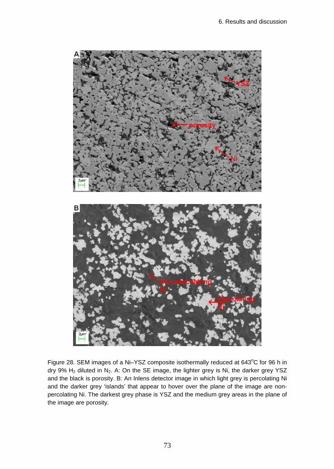
6. Results and discussion
73
Figure 28. SEM images of a Ni–YSZ composite isothermally reduced at 643oC for 96 h in dry 9% H2 diluted in N2. A: On the SE image, the lighter grey is Ni, the darker grey YSZ and the black is porosity. B: An Inlens detector image in which light grey is percolating Ni and the darker grey ‘islands’ that appear to hover over the plane of the image are non-percolating Ni. The darkest grey phase is YSZ and the medium grey areas in the plane of the image are porosity.

6. Results and discussion
74
Figure 29. SEM images of a Ni–YSZ composite isothermally reduced at 884oC for 96 h in dry 9% H2 diluted in N2. A: On the SE image, the lighter grey is Ni, the darker grey YSZ and the black is porosity. B: An Inlens detector image in which light grey is percolating Ni and the darker grey ‘islands’ that appear to hover over the image are non-percolating Ni. The darkest grey phase is YSZ and the medium grey areas in the plane of the image are porosity.

6. Results and discussion
75
Regarding the effect of redox cycling on the electrical conductivity of the cermets, the experiments showed that the conductivity doubles (permanently) after a redox cycle at low temperatures, as long as the subsequent operation is done in conditions (temperature, humidity) where significant Ni sintering can be avoided. After the initial reduction in wet hydrogen of the baseline NiO–YSZ composite, the electrical conductivity at 600oC is slightly below 1,200 S/cm as was shown in Figure 25 (up to 10,000 min). The two re-oxidations in air (at about 10,000 and 20,000 min into the test, respectively) initially improve the conductivity to about 2,200–2,300 S/cm; the conductivity remained in excess of 2,000 S/cm during the tested re-reduction periods. Based on electron microscopy the measured increase in conductivity of the Ni-cermet can be attributed to an improved percolation of the nickel phase in the structure and strain-relocation of the Ni into smaller grains within the composite. The microstructure shown in Figure 30 represents the improved conductivity of about 2,000 S/cm of the base-line cermet after two redox cycles. When similar isothermal redox cycles were carried out at 850oC, there was no resulting improvement in conductivity; in-stead, conductivity trends were largely repetitive with very rapid initial degrada-tion in the successive redox cycles, as shown in Figure 26.
It is interesting to compare the microstructure in Figure 30 to the images of similar baseline cermet after the first reduction at 643oC, Figure 28. Although the microstructure was fine after the low temperature reduction (Figure 28), it became even finer after redox cycling at 600oC (Figure 30). The qualitative assessment from the images is that the characteristic microstructural dimension is decreased and the degree of Ni percolation improves as a result of low temperature redox cycling. Quantitative image analysis on the micrographs was not carried out.
Figure 29, on the other hand, clearly shows sintering and particle growth in the Ni phase after operation at 884oC, combined with a loss of percolation in the Ni phase. In the case of two redox cycles at 850oC, the Ni microstructure ap-peared relatively similar to the Ni microstructure only after the initial reduction (Figure 29). However, related studies have shown that during the two redox cycles of the baseline cermet at 850oC, the ceramic YSZ backbone has already suffered significant micro damage [113] due to excessive stress [48]. The proc-esses leading to the changes in the Ni phase and the thermomechanical conse-quences were recently discussed in related papers [114] [115]. The observed refinement of the Ni microstructure and the related improvement in the electrical conductivity upon low temperature redox cycling is a result of the plas-tic/pseudoplastic deformation of the Ni/NiO phase during the re-oxidation. The

6. Results and discussion
76
low temperature re-oxidation smears the expanding Ni/NiO phase against the microstructure of the ceramic YSZ network without breaking the latter, and the deforming NiO phase can constitute a new and improved percolating Ni network with an enhanced electrical conductivity in the subsequent re-reduction. On the other hand, redox cycling at 850oC leads to a more aggressive Ni/NiO phase where the Ni phase remains coarser and the re-oxidation phase tends to lead to the mechanical degradation of the composite.

6. Results and discussion
77
Figure 30. SEM images of a Ni–YSZ composite isothermally redox cycled at 600oC with wet H2 present during the reduction periods; re-oxidations were done by flushing the test chamber with air. The figure represents the cermet microstructure at the end of the third reduction period. A: The SE image with the lighter grey is Ni, the darker grey YSZ and the black is porosity. B: An Inlens detector image where light grey is percolating Ni, the few darker grey ‘islands’ that appear to hover over the plane of the image are non-percolating Ni. The darkest grey phase is YSZ and the medium grey areas in the plane of the image are porosity.

7. Summary and conclusions
78
7. Summary and conclusions Most pre-commercial SOFC systems are based on Ni–YSZ composite anodes. Such cermets are often also used as structurally bearing supports for the cells. An operating Ni-based SOFC can get severely damaged by an inadvertent exposure of the anode to an oxidising atmosphere at a high temperature – a re-oxidation (or a redox cycle). The combination of the operating conditions, the cermet microstruc-ture, the composition and the thermomechanical properties can cause excessive expansion of the anode composites. The origin of the problem is the volumetric expansion of Ni upon oxidation to NiO and it often leads to the well-known and inherent redox stability failure in the anode-supported thin electrolyte cells. The redox sequence involves a complex interplay of different processes and parameters of importance, as sketched in Figure 31; a complete picture of the problem can only be obtained by combining information from different sources.
A central means to improve this Achilles’ heel is to design and prepare a di-mensionally stable anode half cell that does not overload the electrolyte upon re-oxidation. This work deals with fundamental investigations to better understand the behaviour of Ni–YSZ composites during redox cycling. The focus was to understand the internal dependencies of the composite that lead to redox expan-sion, and to find ways to design and manufacture modified anode support struc-tures with improved stability. Table 1 summarises the different experimental conditions investigated by the different techniques, based on Chapter 6.
This work demonstrated that the dimensional stability during redox cycling is highly dependent on the temperature of operation and humidity. Both affect the growth of Ni particles through sintering – understood as the growth, migration and coalescence of Ni grains that minimise the surface energy. The initial reduc-tion of NiO to Ni increases the porosity of the composite and creates new free volume in the composite. Upon re-oxidation, when the expansion of the grown Ni grains cannot be accommodated by the porosity in the composite, bulk ex-

7. Summary and conclusions
79
pansion of the substrate is observed. The growth of Ni grains is also dependent on the particle size and size distribution of the Ni grains. Ni sintering is drasti-cally increased if the temperature exceeds approximately 800oC, and even more so if the reducing gas is wet; on the other hand, the presence of steam does not lead to significant Ni sintering if the temperature remains below about 700oC.
Figure 31. A schematic of the interplay of processes, parameters and experimental tech-niques of relevance when investigating redox stability.
The high-temperature re-oxidation of micron-sized Ni grains embedded in a porous YSZ matrix starts as an extremely fast interface reaction where a grow-ing oxide film is created. After the initial fast oxidation of up to about 30% de-gree of oxidation, the oxidation slows down to parabolic or logarithmic kinetics. Furthermore, a decrease in temperature slows down the reaction kinetics drasti-cally during both reduction and re-oxidation. It was observed that a redox cycle at 600oC sped up the subsequent re-reduction significantly, indicating a change in microstructure due to the re-oxidation. This observation was confirmed by the permanent doubling of the electrical conduc-tivity of the cermets on redox cycling at 600oC and the related microscopy analysis. The improvement was attributed to the refinement of the Ni micro-structure. Further, electrical measurements showed an extremely rapid degrada-tion of conductivity above approximately 800oC due to the sintering of Ni and an

7. Summary and conclusions
80
amplification of the degradation in the presence of steam. In contrast, the electri-cal conductivity was stable at 600–650oC, even in wet conditions.
Table 1. Summary of the experimental cases and conditions investigated in the work. Under conditions, dry refers to untreated gas, humid to humidification using a water bottle, and wet means significant partial pressures of steam.
Condition Dilatometry TGA IET Conductivity EIS
dry - red-ox kinetics (A) - - -
500oC humid - - - - -
dry reduction redox (A)
red-ox kinetics (A)
elastic propertiesdamping**
(A, B)
degradation redox (A, B)
-
humid reduction redox (A, B) - -
degradation redox (A, B)
redox 600oC
wet - - - degradation
redox (A, B)
-
dry reduction redox (A, B)
red-ox kinetics (A)
elastic propertiesdamping (A, B)
degradation redox (A, B)
- 750oC
humid - red-ox kinetics (A) - - -
dry reduction redox (A, B)
red-ox kinetics (A, B)
elastic propertiesdamping (A, B)
degradation redox (A, B)
-
humid reduction redox (A)
red-ox kinetics (A) -
degradation redox (A, B)
redox 850oC
wet - - - degradation
redox (A, B)
-
dry reduction redox (A)
red-ox kinetics (A)
elastic propertiesdamping (A, B)
degradation (A, B) -
1000oC humid - red-ox kinetics
(A) - - -
1100–1200oC dry reduction
(A) - elastic propertiesdamping* (A) - -
*only NiO–YSZ ** different reduction temperatures, ramping experiment to a high temperature A – baseline cermets investigated B – modified cermets investigated

7. Summary and conclusions
81
The temperature of the re-oxidation was found to be of crucial importance for the thermomechanical behaviour of the composite. Low-temperature redox cy-cles of Ni–YSZ composites below 700oC were dimensionally reversible and did not lead to mechanical rupture. Increasing micro and macro damage occurred in the ceramic backbone at higher temperatures; re-oxidation at high temperatures (850oC or higher) leads to larger redox expansion.
The dimensional changes and the resulting thermomechanical behaviour of the SOFC in redox conditions are highly dependent on the supporting composite microstructure – porosity was confirmed to be an important parameter. Gener-ally, as porosity of the composite increases (at least up to as-sintered porosities of about 35%), redox stability is improved. At even higher porosities, the me-chanical strength of the structure may no longer be sufficient.
The mechanical properties of the composites were determined for both Ni–YSZ and NiO–YSZ composites as a function of porosity, temperature and redox cycling. The elastic properties of the composites were found to depend linearly on porosity. The specific damping measured by Impulse Excitation technique increased with temperature and for the Ni–YSZ cermets, damping was found to be a sensitive function of microstructure; a cermet with a fine Ni phase after a low-temperature reduction showed higher specific damping and rapid changes during the test due to Ni sintering. The elastic properties of the composites de-graded linearly with the cumulative (permanent) redox strain when the strain exceeded about 0.5%.
Particle growth due to the build-up of porosity within the oxidised Ni grains combined with the capability of the oxidising Ni/NiO phase to deform by pseu-doplasticity and microcracking appear to be decisive factors in terms of the redox stability of the composite. Such nonelastic strains in the NiO phase may alleviate the redox stress exerted on the YSZ backbone; further solutions should be sought to enable such stress relaxation.
Stress relaxation by strains in the Ni/NiO phase during oxidation was found by experiments and modelling to be more pronounced when the oxidation tem-perature was about 750oC or lower. Redox cycling at about 800oC or higher rap-idly leads to irreversible nonelastic strains in the YSZ backbone. These can be micro and later macrocracking causing mechanical degradation, or at the highest temperatures, also creep and grain boundary sliding (GBS) of the YSZ phase. Repeated redox cycles with accumulating nonelastic YSZ strains will result in the rupture of the ceramic backbone.

7. Summary and conclusions
82
Finally, it should be noted that even when the anode support is redox stable, excessive stress from the dimensional changes of the anode may overload and fracture the electrolyte. Therefore, the combination of mild operation conditions and an improved microstructure and composition of the anode support and anode appear to be a plausible solution to the problem. Optimisation of the anode half cell and an intentional low-temperature redox treatment could lead to an im-provement of the start-up performance or recover the performance of a degraded anode support or a used anode (after a period of operation). The durability and stability of the anode could potentially be improved by modifying the micro-structure and composition of the composites.

8. Outlook
83
8. Outlook Solid oxide fuel cells continue to be an important subject for academic research. At the same time, it is rapidly becoming necessary to show real technological progress towards commercialisation and market applications. The main techno-logical challenge impeding the market breakthrough for SOFC is that many of the aspects including materials, the cell and stack design as well as the system performance and cost still require improvement.
In the present work, a detailed characterisation was done on Ni–YSZ compos-ites suitable for use as anode supports in SOFC. As demonstrated, a significant improvement in the redox stability of the Ni–YSZ composite was achieved by microstructural and compositional variation. Such variations have to be taken into account when preparing full cells by ceramic processing. Subsequent to the manufacture and testing of the modified anode support composites, the design and manufacture of the half cells based on these supports was initiated but not completed during the work. The stable performance of the full solid oxide cell under redox cycling is the technically relevant finding that verifies the ther-momechanical redox stability. In tests yet unpublished, it has been verified that oxide cells based on the baseline support fail upon aggressive redox cycling. In terms of the modified structures designed as part of this work, the remaining technological step is to successfully prepare modified cells with a tight electro-lyte and demonstrate their redox properties – recent work on this at Risø shows encouraging results. After this, the microstructures of the anode support and the anode could feasibly be optimised, along with the compositions, including dopants with the most potential. This optimisation shall comprise the entire ce-ramic processing route combined with selected single effects experiments. As the final demonstration for their viability in real applications, stack tests should be considered to compare the baseline cells and the modified cells in realistic operation schemes regarding performance and redox stability.

Acknowledgements
84
Acknowledgements Many people deserve a heartfelt thank you now that this project reaches its pin-nacle. My initial contact with Risoe came through Mogens Mogensen who, to-gether with Andreas Kaiser, was very helpful in writing the successful Marie Curie proposal with me. I also want to thank Peter Halvor Larsen and Søren Linderoth for employing me at Risø, and Peter Vang Hendriksen for extending my stay at Risø.
Andreas Kaiser was my supervisor and closest co-worker, had an excellent prior hands-on knowledge of the subject, and gave superb feedback throughout the work. Mogens Mogensen was fantastic in scientific coaching and always there for a discussion. Peter Halvor Larsen was the key person to enable the wonderful support from the ceramic processing group and the pre-pilot labora-tory at Risø. The help from Karen Brodersen was indispensable for the success in ceramic processing, with excellent support from Henrik Paulsen, Jette Iversen, Lene Knudsen, Severine Ramousse, Mats Lundberg and several TOFC people. Mohan Menon often gave insightful suggestions on how to proceed when I was not sure what to do. Regarding thermal analysis, Carsten Gynther Sørensen was great in technical support; equally, John Johnson helped with furnaces. Nikos Bonanos was a posi-tive and proficient supporting person regarding the electrical and electrochemi-cal measurements as well as the continuum mechanics modelling. I had much advantage from having smooth access to previous work and experience in elec-trical measurements by Karl Thydén, and redox stability work by Trine Klemensø. The people in the ceramic laboratory were helpful whenever there was a practical problem, especially Ebtisam Abdellahi, Charlotte Maul and Annelise Hoffbeck.
Since I am not a microscopist myself, I had obviously tremendous help from experienced people to get started in that area, including Yi-Lin Liu, Karl Thy-

Acknowledgements
85
dén, Jake Bowen and Jesper Knudsen. Ming Chen was a competent support in thermodynamic modelling and calculations.
I want to sincerely thank all my co-authors for the nice work together, espe-cially Tania Ramos and Henrik Lund Frandsen – I really enjoyed working with you. Tania was a brilliant anode group leader and also took over some of my development activities upon my departure. Also, I was also very happy to work together with Antonin Faes from EPFL during his visit at Risø. Furthermore, I want to thank Johan Hjelm, Peter Blennow, Per Hjalmarsson, Karl, Mats, Jonas Östby and Nadja Lönnroth for the cosy Swedish-Finnish dimension.
Co-operation with TOFC worked well. I want to thank Rasmus Barfod for feedback and discussions, Uffe Rahbek for support in sample preparation and sintering, and Niels Christiansen, Mette Juhl Jørgensen and Søren Primdahl for manuscript and thesis reading, comments and acceptance.
Financial support was obtained from Svenska Litteratursällskapet i Finland r.f. (2005); Nordic Energy Research, Fuel Cell Net (2006); Marie Curie Intra-European Fellowship, contract number MEIF-CT-2005-023882 (2006–2008), as part of the European Commission’s 6th framework programme; and Energi-net.dk under the project PSO 2007-1-7124 SOFC R&D (2008). This support is gratefully acknowledged. Erkko Fontell and Timo Kivisaari of Wärtsilä Corpo-ration are acknowledged for supporting the Marie Curie application. Professor Peter Lund of Aalto University was very helpful both in the initial phase includ-ing the preparation of funding applications, and in the final phase of the thesis.
Finally, I want to thank VTT Technical Research Centre of Finland, Rolf Rosenberg and Jari Kiviaho, for the possibility for me to join the VTT SOFC team and to finish this thesis at VTT. Olli Himanen of VTT is acknowledged for proof reading and comments to the present manuscript.

86
References [1] IPCC Synthesis Report 2007, Contribution of Working Groups I, II and III to the Fourth
Assessment Report of the Intergovernmental Panel on Climate Change, Core Writing Team, Pachauri, R. K., Reisinger, A. (Eds.). IPCC, Geneva, Switzerland. P. 104.
[2] NASA Goddard Institute for Space Studies, Surface Temperature Analysis, http://data.giss.nasa.gov/gistemp/.
[3] International Energy Agency, Medium-term Oil Market Report, July 2007, www.oilmarketreport.org.
[4] http://en.wikipedia.org/wiki/Olkiluoto_Nuclear_Power_Plant.
[5] M. Winter, R. J. Brodd, Chemical Reviews 2004 (104) 4245–4269.
[6] U. Bossel, The Birth of the Fuel Cell, European Fuel Cell Forum, Oberrohrdorf, Swit-zerland, 2000. ISBN 3-905592-06-1.
[7] S. C. Singhal, K. Kendall, High Temperature Solid Oxide Fuel Cells, Fundamentals, Design and Applications, Elsevier, Amsterdam, 2003.
[8] H. Yokokawa, H. Tu, B. Iwanschitz, A. Mai, Journal of Power Sources 182 (2008) 400–412.
[9] W. Z. Zhu, S. C. Deevi, Materials Science and Engineering A362 (2003) 228–239.
[10] Fuel Cell Test and Evaluation Center (FCTec), U.S. Department of Defence. http://www.fctec.com/fctec_types_sofc.asp.
[11] A. Mai, B. Iwanschitz, U. Weissen, R. Denzler, D. Haberstock, V. Nerlich, J. Sfeir, A. Schuler, ECS Transactions 25 (2) 149–158 (2009).
[12] S. Kluge, O. Posdziech, B. E. Mai, J. Lawrence, ECS Transactions 25 (2) 247–256 (2009).
[13] A. Glauche, T. Betz, S. Mosch, N. Trofimenko, M. Kusnezoff, ECS Transactions 25 (2) 411–419 (2009).
[14] N. Christiansen, J. B. Hansen, H. Holm-Larsen, M. J. Jørgensen, M. Wandel, P. V. Hendriksen, A. Hagen, S. Ramousse, ECS Transactions 25 (2) 133–142 (2009).
[15] M. Bertoldi, O. Bucheli, A. Ravagni, N. Autissier, M. Signorini, S. Modena, ECS Transactions 25 (2) 105–114 (2009).

87
[16] B. Borglum, E. Tang, M. Pastula, ECS Transactions 25 (2) 65–70 (2009).
[17] J. Love, S. Amarasinghe, D. Selvey, X. Zheng, L. Christiansen, ECS Transactions 25 (2) 115–124 (2009).
[18] S. Mukerjee, K. Haltiner, D. Klotzbach et al., ECS Transactions 25 (2) 59–63 (2009).
[19] K. Kendall, C. M. Dikwal, ECS Transactions 25 (2) 899–906 (2009)
[20] C. M. Dikwal, W. Bujalski, K. Kendall, Journal of Power Sources 181 (2008) 267–273.
[21] A. Atkinson, S. Barnett, R. J. Gorte, J. T. S. Irvine, A. J. McEvoy, M. Mogensen, S. C. Singhal, J. Vohs, Nature materials 3 (2004), pp. 17–27.
[22] M. C. Tucker, T. Z. Sholklapper, G. Y. Lau, L. C. DeJonghe, S. J. Visco, ECS Transactions 25 (2) 673–680 (2009).
[23] P. Blennow, J. Hjelm, T. Klemensø, Å. Persson, K. Brodersen, A. K. Srivastava, H. L. Frandsen, M. Lundberg, S. Ramousse, M. Mogensen, ECS Transactions 25 (2) 701–710 (2009).
[24] D. Munz, T. Fett, Ceramics – Mechanical Properties, Failure Behaviour, Materials Selection, Springer, Berlin 1999.
[25] W. D. Kingery, H. K. Bowen, D. R. Uhlmann, Introduction to Ceramics, 2nd Ed, John Wiley & Sons, New York, 1976.
[26] G. E. Dieter, Mechanical Metallurgy, SI Metric Edition, Mc Graw-Hill, Singapore, 1988.
[27] M. Radovic, E. Lara-Curzio, Acta Materialia 52 (2004) 5747–5756.
[28] M. Radovic, E. Lara-Curzio, J. Am. Ceram. Soc. 87 [12] 2242–2246 (2004).
[29] A. Morales-Rodríguez, A. Bravo-León, A. Domínguez-Rodríguez, S. Lopez-Esteban, J. S. Moya, M. Jiménez-Melendo, Journal of the European Ceramic Society 23 (2003) 2849–2856.
[30] A. Morales-Rodríguez, A. Bravo-León, G. Richter, M. Rühle, A. Domıínguez-Rodrıíguez, M. Jiménez-Melendo, Scripta Materialia 54 (2006) 2087–2090.
[31] S. Lopez-Esteban, J. F. Bartolome, J. S. Moya, T. Tanimoto, J. Mater. Res. 2002 (17) 1592–1600.
[32] J. S. Moya, S. Lopez-Esteban, C. Pecharromán, Progress in Materials Science 52 (2007) 1017–1090.

88
[33] M. Yashima, M. Kakihana, M. Yoshimura, Solid State Ionics 86–88 (1996) 1131–1149.
[34] J. W. Fergus, Journal of Power Sources 162 (2006) 30–40.
[35] M. Matsuzawa, E. Fujimagari, S. Horibe, Mat. Sci. Eng. A314 (2001) 105–109.
[36] M. Matsuzawa, F. Sato, S. Horibe, J. Mat. Sci. 36 (2001) 2491–2497.
[37] M. Jiménez-Melendo, A. Domínguez-Rodríguez, Acta Mater. 48 (2000) 3201–3210.
[38] A. Domínguez-Rodríguez, D. Gómez-García, M. Castillo-Rodríguez. J. Eur. Cer. Soc. 28 (2008) 571–575.
[39] N. Q. Minh, J. Am. Cer. Soc. 76 [3] (1993) 563–588.
[40] R. M. C. Clemmer, S. F. Corbin, Solid State Ionics 180 (2009) 721–730.
[41] A. V. Virkar, J. Chen, C. W. Tanner, J.-W. Kim, Solid State Ionics 131 (2000) 189–198.
[42] M. Mori, T. Yamamoto, H. Itoh, H. Inaba, H. Tagawa. J. Electrochem. Soc. 145 (1998) 1374–1381.
[43] I. A. Menzies, K. N. Strafford, J. Mat. Sci. 2 (1967) 358–364.
[44] R. Farraro, R. B. McLellan, Metallurgical Transactions A Vol. 8A (1977) 1563–1565.
[45] A. Atkinson, A. Selcuk, Solid State Ionics 134 (2000) 59–66.
[46] M. Cassidy, G. Lindsay, K. Kendall, Journal of Power Sources 61 (1996) 189–192.
[47] G. Robert, A. Kaiser and E. Batawi, In: proceedings of the 6th European SOFC Forum, Lucerne, Switzerland 2004, 193.
[48] T. Klemensø, C. Chung, P. H. Larsen, M. Mogensen, J. Electrochem. Soc. 152 (2005) A2186–A2192.
[49] T. Klemensø, M. Mogensen, J. Am. Ceram. Soc. 90 (2007) 3582–3588.
[50] T. Klemensø, Relationships between structures and performance of SOFC anodes, PhD thesis, Technical University of Denmark, 2005.
[51] A. Faes, Q. Jeangros, J. B. Wagner, T. W. Hansen, J. Van herle, A. Brisse, R. Dunin-Borkowski, A. Hessler-Wyser, ECS Transactions 25 (2) 1985–1992 (2009).
[52] D. Sarantaridis, R. J. Chater, and A. Atkinson, J. Electrochem. Soc. 155 (2008) B467–B472.

89
[53] D. Fouquet, A. C. Muller, A. Weber, E. Ivers-Tiffee, Ionics 8 (2003), p. 103.
[54] D. Waldbillig, A. Wood, D.G Ivey, Solid State Ionics 176 (2005) 847–859.
[55] N. M. Tikekar, T. J. Armstrong, A. V. Virkar, J. Electrochem. Soc. 153 (4) A654–A663 (2006).
[56] G. Stathis, D. Simwonis, F. Tietz, A. Moropolou, A. Naoumides, J. Mater. Res. 17 (2002) 951–958.
[57] M. Ettler, G. Blaß, N. H. Menzler. Fuel Cells 7 (2007) 349–355.
[58] M. Ettler, Einfluss von Reoxidationszyklen auf die Betriebsfestigkeit von anodenge-stützten Festoxid-Brennstoffzellen, PhD Thesis, Forschungszentrum Jülich, 2008, ISBN 978-3-89336-570-8.
[59] D. Waldbillig, A. Wood, D.G. Ivey, Journal of Power Sources 145 (2005) 206–215.
[60] A. Faes, A. Nakajo, A. Hessler-Wyser, D. Dubois, A. Brisse, S. Modena, J. van Herle, Journal of Power Sources 193 (2009) 55–64.
[61] J. Malzbender, E. Wessler and R. W. Steinbrech, Solid State Ionics 176 (2005) 2201–2203.
[62] D. Sarantaridis and A. Atkinson. In: proceedings of the 7th European SOFC Forum, Lucerne, Switzerland 2006, paper P0728.
[63] J. Laurencin, G. Delette, F. Lefebvre-Joud, M. Dupeux, J. Eur. Ceram. Soc. 28 (2008) 1857–1869.
[64] D. Sarantaridis and A. Atkinson, Fuel Cells 7 (2007) 246–258.
[65] D. Sarantaridis, Redox Cycling of Solid Oxide Fuel Cells, PhD Thesis, Imperial College, London, January 2008.
[66] D. Sarantaridis, R. A. Rudkin, A. Atkinson, Journal of Power Sources 180 (2008) 704–710.
[67] J. Laurencin, G. Delette, B. Morel, F. Lefebvre-Joud, M. Dupeux, Journal of Power Sources 192 (2009) 344–352.
[68] A. Wood, M. Pastula, D. Waldbillig, D. G. Ivey, J. Electrochem. Soc. 153 (2006) A1929–A1934.
[69] S. Tao, J. T. S Irvine, Nature materials 2 (2003) 320–323.

90
[70] H. Itoh, T. Yamamoto, M. Mon, T. Horita, N. Sakai, H. Yokokawa, M. Dokiya, J. Elec-trochem. Soc. 144 (1997) 641–646.
[71] D. Waldbillig, A. Wood, D. G. Ivey, J. Electrochem. Soc. 154 (2007) B133–B138.
[72] A. N. Busawon, D. Sarantaridis, A. Atkinson, Electrochemical and Solid-State Letters, 11 (2008) B186–B189.
[73] R. Ihringer, ECS Transactions 25 (2) 473–483 (2009).
[74] M. Pihlatie, A. Kaiser, P. H. Larsen, M. Mogensen, J. Electrochem. Soc. 156 (2009) B322–B329.
[75] P. Kofstad, High Temperature Corrosion, Elsevier Applied Science, London 1988.
[76] A. Atkinson, Rev. Mod. Phys. 57 (1985) 437–470.
[77] R. Haugsrud, Corrosion Science 45 (2003) 211–235.
[78] H. V. Atkinson, Oxidation of Metals 24 (1985) 353–389.
[79] A. M. Huntz, M. Andrieux, R. Molins, Materials Science and Engineering A 415 (2006) 21–32.
[80] A. Atkinson, R. I. Taylor, Journal of Materials Science 13 (1978) 427–432.
[81] A. Atkinson, D. P. Moon, D. W. Smart, R. I. Taylor, Journal of Materials Science 21 (1986) 1747–1757.
[82] A. W. Harris, J. S. Brown, A. Atkinson, Corrosion Science 34 (1993) 1017–1033.
[83] I. Küppenbender, M. Schütze, Oxidation of Metals 42 (1994) 109–143.
[84] M. Schütze, Oxidation of Metals 25 (1986) 409–421.
[85] R. Haugsrud, Corrosion Science 45 (2003) 1289–1311.
[86] N. Christiansen, J. B. Hansen, H. Holm-Larsen, S. Linderoth, P. H. Larsen, P. V. Hendriksen, M. Mogensen, proceedings of the 7th European SOFC Forum, Lucerne, Switzerland, 2006, paper B034.
[87] S. Ramousse, M. Menon, K. Brodersen, J. Knudsen, U. Rahbek, P. H. Larsen, ECS Transactions 7 (1) (2007) 317–327.
[88] M. Pihlatie, A. Kaiser, P. H. Larsen, M. Mogensen, ECS Transactions 7(1) 1501–1510 (2007).

91
[89] M. Pihlatie, T. Ramos, A. Kaiser, Journal of Power Sources 193 (2009) 322–330.
[90] M. N. Rahaman, Ceramic processing, Taylor & Francis, 2006.
[91] S.-J. Kang, Sintering – Densification, Grain Growth and Microstructure, Elsevier Science & Technology, Oxford, 2004.
[92] J. A. Lewis, J. Am Ceram. Soc. 83 (2000) 2341–2350.
[93] B. C. H. Steele, A. Heinzel, Nature 414 (2001) 345–352.
[94] D. Stöver, H. P. Buchkremer, S. Uhlenbruck, Ceramics International 30 (2004) 1107–1113.
[95] S. Ramousse, M. Menon, K. Brodersen, J. Knudsen, U. Rahbek, P. H. Larsen, ECS Transactions 7 (2007) 317–327.
[96] J. Will, A. Mitterdorfer, C. Kleinlogel, D. Perednis, L. J. Gauckler, Solid State Ionics 131 (2000) 79–96.
[97] D. Simwonis, F. Tietz, and D. Stöver, Solid State Ionics 132 (2000) 241–251.
[98] S. P. Jiang, J. Mater. Sci. 38 (2003) 3775–3782.
[99] J. Sehested, J. A. P. Gelten, I. N. Remediakis, H. Bengaard, J. K. Nørskov, Journal of Catalysis 223 (2004) 432–443.
[100] J. Sehested, J. A. P. Gelten, S. Helveg, Applied Catalysis A: General 309 (2006) 237–246.
[101] M. W. Finnis, J. Phys.: Condens. Matter 8 (1996) 5811–5836.
[102] M. C. Muñoz, S. Gallero, J. I. Beltrán, J. Cerdá, Surface Science Reports 61 (2006) 303–344.
[103] Y.-M. Chiang, D. P. Birnie, W. D. Kingery, Physical Ceramics; Principles for Ce-ramic Science and Engineering, John Wiley & Sons Inc., 1997.
[104] C. Herring, J. App. Phys. 21 (1950) 301–303.
[105] P. Wynblatt, Acta mater. 48 (2000) 4439–4447.
[106] A. Tsoga, P. Nikolopoulos, A. Naoumidis, Ionics 2 (1996) 427–434.
[107] X. Mantzouris, N. Zouvelou, D. Skarmoutsos, P. Nikolopoulos, F. Tiezt, J. Mat. Sci. 40 (2005) 2471–2475.
[108] R. Vassen, D. Simwonis, D. Stöver, J. Mater. Sci. 36 (2001) 147–151.

92
[109] M. Pihlatie, A. Kaiser, M. Mogensen, M. Chen, Electrical conductivity of Ni–YSZ composites: degradation due to Ni particle growth, to be submitted for publica-tion to Solid State Ionics.
[110] L. Grahl-Madsen, P. H. Larsen, N. Bonanos, J. Engell, S. Linderoth, J. Mater. Sci. 41 (2006) 1097–1107.
[111] J. L. Young, V. Vedahara, S. Kung, S. Xia, V. I. Birss, ECS Transactions 7 (2007) 1511–1519.
[112] M. Pihlatie, A. Kaiser, M. Mogensen, Electrical conductivity of Ni–YSZ composites – cermet variants and redox cycling, to be submitted for publication to Solid State Ionics.
[113] M. Pihlatie, A. Kaiser, M. Mogensen, J. Eur. Cer. Soc. 29 (2009) 1657–1664.
[114] M. Pihlatie, A. Kaiser, M. Mogensen, Solid State Ionics 180 (2009) 1100–1112.
[115] M. Pihlatie, H. L. Frandsen, A. Kaiser, M. Mogensen, Journal of Power Sources 195 (2010) 2677–2690.
[116] K. Thydén, Y. L. Liu, J. B. Bilde-Sørensen, Solid State Ionics 178 (2008) 1984–1989.
Appendices of this publication are not included in the PDF version. Please order the printed version to get the complete publication (http://www.vtt.fi/publications/index.jsp).

Series title, number and report code of publication
VTT Publications 740 VTT-PUBS-740
Author(s) Mikko Pihlatie Title
Stability of Ni–YSZ composites for solid oxide fuel cells during reduction and re-oxidation
Abstract An operating Ni-based SOFC can be severely damaged by inadvertent oxidation of the nickel. A central way to improve this Achilles’ heel is to design and prepare a dimension-ally stable anode half cell that does not overload the electrolyte upon re-oxidation. Under-standing the mechanisms that lead to the redox expansion, and designing and manufac-turing modified anode support structures that improve stability have been the core of the present work.
The behaviour of Ni–YSZ cermets for SOFCs were characterised under conditions cy-clically altered between reducing and oxidising (redox cycling). The main operating condi-tions that affect redox stability were shown to be temperature and humidity; both affect the growth of Ni particles through sintering. The temperature of re-oxidation also played a significant role in redox stability; a re-oxidation at a high temperature (850oC or higher) leads to larger expansions.
The behaviour of the cermet under redox conditions is highly dependent on microstruc-ture; as porosity of the composite increases, redox stability is improved. A redox cycle at 600oC sped up the subsequent re-reduction significantly, indicating a change in micro-structure due to the re-oxidation; also the electrical conductivity of the cermets improved on such a redox cycle. The redox strains during redox cycles below 700oC were reversi-ble, while cumulating strain and damage was created in the ceramic backbone at ele-vated temperatures.
NiO particle growth during oxidation, combined with low temperature pseudoplasticity was shown to be a decisive factor for redox stability. Redox cycling at high temperatures rapidly leads to irreversible nonelastic strains (cracking, creep) in the YSZ backbone that cause mechanical degradation.
The combination of mild operating conditions and redox-improved cells appears to be a plausible solution to circumvent redox failures. An intentional low-temperature redox treatment could lead to an improvement in performance. The durability and stability of the anode can be improved by modifications in the microstructure and the composition of the cermets. ISBN 978-951-38-7400-1 (paperback ed.) 978-951-38-7401-8 (URL: http://www.vtt.fi/publications/index.jsp)
Series title and ISSN Project number
VTT Publications 1235-0621 (paperback ed.) 1455-0849 (URL: http://www.vtt.fi/publications/index.jsp)
41902
Date Language Pages May 2010 English, Finnish abstr. 92 p. + app. 62 p.
Keywords Publisher Fuel cell, SOFC, Ni–YSZ, Ni cermet, redox stability, thermomechanics, sintering, continuum mechanics, creep, viscoelastic, NiO reduction, Ni oxidation, kinetics
VTT Technical Research Centre of Finland P.O. Box 1000, FI-02044 VTT, Finland Phone internat. +358 20 722 4520 Fax +358 20 722 4374


Julkaisun sarja, numero ja raporttikoodi
VTT Publications 740 VTT-PUBS-740
Tekijä(t) Mikko Pihlatie Nimeke
Kiinteäoksidipolttokennon Ni–YSZ-komposiittien stabiilisuus pelkistävissä ja hapettavissa olosuhteissa Tiivistelmä Nikkelipohjainen kiinteäoksidipolttokenno voi vaurioitua, jos kennon anodille syntyy yllät-täen nikkeliä hapettavat olosuhteet. Hapettumisen seurauksena anodirakenne paisuu ja voi rikkoa kennon keraamisen elektrolyytin. Työn keskeisenä sisältönä oli ymmärtää mitta-muutosta aiheuttavat mekanismit ja kehittää kennotason lähestymistapoja tämän ns. re-dox-ongelman ratkaisemiseksi, sekä suunnitella ja valmistaa redox-stabiileja anodi-komponentteja ja puolikennoja.
Polttokennojen anodirakenteiksi soveltuvia Ni–YSZ -komposiitteja tutkittiin tässä työssä koejärjestelyissä, joissa korkean lämpötilan kaasukehää vaihdeltiin toistuvasti hapettavan ja pelkistävän välillä (ns. redox-syklit). Tärkeimmät stabiilisuuteen vaikuttavat parametrit olivat lämpötila ja kosteus – molemmat lisäävät nikkelin raekoon kasvua (sintrautumista). Myös nikkelin uudelleenhapettumisen lämpötilalla oli suuri vaikutus komposiitin mitta-muutokseen: hapetus korkeissa lämpötiloissa (850 °C tai yli) aiheutti suuremman mittamuu-toksen.
Komposiitin mikrorakenne vaikutti keskeisesti sen stabiilisuuteen; yleisesti kun rakenteen huokoisuus kasvoi, stabiilisuus parani. Redox-sykli 600 °C:ssa nopeutti uudelleenpelkistystä, mikä osoitti komposiitin mikrorakenteen muuttuneen; myös sähkönjohtavuus parani oleellisesti. Mittamuutokset uudelleenhapetuksissa alle 700 °C:ssa olivat pitkälti palautuvia. Lämpötilan nostaminen aikaansai pysyvän mittamuutoksen ja mekaanisia mikro- ja makrorakenteen vaurioita.
NiO-faasin käyttäytyminen uudelleenoksidoinnissa ja jännitysten relaksoituminen pseu-doplastisuuden kautta osoittautui keskeiseksi tekijäksi. Pseudoplastista relaksoitumista tapahtui alhaisen lämpötilan uudelleenhapetuksissa.
Tulosten perusteella mahdollinen ratkaisu redox-ongelmaan on käyttää rakenteeltaan parannettuja kennoja suotuisissa käyttöolosuhteissa. Tahallinen alhaisen lämpötilan re-dox-sykli voi jopa parantaa kennojen suorituskykyä. Anodin kestävyyttä ja stabiilisuutta voidaan parantaa muokkaamalla sen mikrorakennetta ja koostumusta. ISBN 978-951-38-7400-1(nid.) 978-951-38-7401-8 (URL: http://www.vtt.fi/publications/index.jsp)
Avainnimeke ja ISSN Projektinumero VTT Publications 1235-0621 (nid.) 1455-0849 (URL: http://www.vtt.fi/publications/index.jsp)
41902
Julkaisuaika Kieli Sivuja Toukokuu 2010 Englanti, suom. tiiv. 92 s. + liit. 62 s.
Avainsanat Julkaisija
Fuel cell, SOFC, Ni–YSZ, Ni cermet, redox stability, thermomechanics, sintering, continuum mechanics, creep, viscoelastic, NiO reduction, Ni oxidation, kinetics
VTT PL 1000, 02044 VTT Puh. 020 722 4520 Faksi 020 722 4374

4
Dissertation VTT PUBLICATIONS 740VTT CREATES BUSINESS FROM TECHNOLOGYTechnologyandmarketforesight•Strategicresearch•Productandservicedevelopment•IPRandlicensing•Assessments,testing,inspection,certification•Technologyandinnovationmanagement•Technologypartnership
•••VTTPUB
LICA
TION
S740STA
BILITyO
fNI–ySZC
Om
POSITeSfO
RSO
LIdO
xIdefU
eLCeLLSd
UR
INg
Red
UC
TION
AN
dR
e-OxId
ATIO
N
ISBN 978-951-38-7400-1 (paperback ed.) ISBN 978-951-38-7401-8 (URL: http://www.vtt.fi/publications/index.jsp)ISSN 1235-0621 (paperback ed.) ISSN 1455-0849 (URL: http://www.vtt.fi/publications/index.jsp)
Mikko Pihlatie
Stability of Ni–YSZ composites for solid oxide fuel cells during reduction and re-oxidation
Solid oxide fuel cells (SOFC) are ceramic electrochemical devices for direct conversion of hydrocarbons into electricity and heat at a high electrical efficiency. While the technology shows great promise, both cost and durability have to be improved. State-of-the-art SOFC anodes and anode supports are made of ceramic-metal composites of Ni and YSZ. Such cermets are thus far superior in terms of anode performance, but are susceptible to a redox failure if the nickel is inadvertently re-oxidised. This can be a life-limiting occurrence for a solid oxide cell and a costly headache for a SOFC system developer to deal with. The present thesis investigates the redox stability problem of Ni-based SOFC. The internal processes leading to the redox instability of the composites are analysed in detail both experimentally and through continuum mechanics modelling. The mechanisms as well as the parameters of importance are discussed. The thesis contributes to the understanding of the redox instability problem and to the manufacturing of more robust and durable solid oxide fuel cells.