stability behavior of plate girders with laterally ... · the tested girders shown in fig. 2 were...
TRANSCRIPT
Journal of Civil Engineering and Architecture 10 (2016) 391-404 doi: 10.17265/1934-7359/2016.04.001
Stability Behavior of Plate Girders with Laterally
Unbraced Ends
Yiyun Zhu and Jing Jiang
Department of Civil Engineering, Shanghai Jiao Tong University, Shanghai 200240, China
Abstract: Stability tests of three plate girders laterally unbraced on both ends, which were scale models of real plate girders in heavy plants for tower-type boilers, are presented and investigated. The applicability of code provisions in ANSI/AISC 360-10 about such members is discussed. A nonlinear finite element analysis was carried out, considering the combined effects of plasticity, residual stress and geometrical imperfections, to simulate the stability behavior of the specimens. The reliability of the numerical model was validated by comparisons with experimental results. The results show that stability behavior of plate girders with laterally unbraced ends is widely different from that of typical simply supported thin-walled beams. The structural response is also sensitive to initial geometrical imperfections of this objects. The model is used to improve the mechanical design of transverse stiffeners over the supports. The positive effect and offsetting influence of imperfections of thicker and additional transverse stiffeners on overall stability behavior are highlighted. A few suggestions for design process are also given.
Key words: Plate girder, lateral-torsional buckling, boundary condition, numerical modeling, ANSI/AISC 360-10.
1. Introduction
Steel plate girders are used to suspend the
tower-type boilers in heavy power plants, the span
length of which can exceed 40 m and the depth of
sections can reach 8~10 m. Such giant form is not
generally possible in ordinary engineering structures.
Besides the deep and narrow cross section, the support
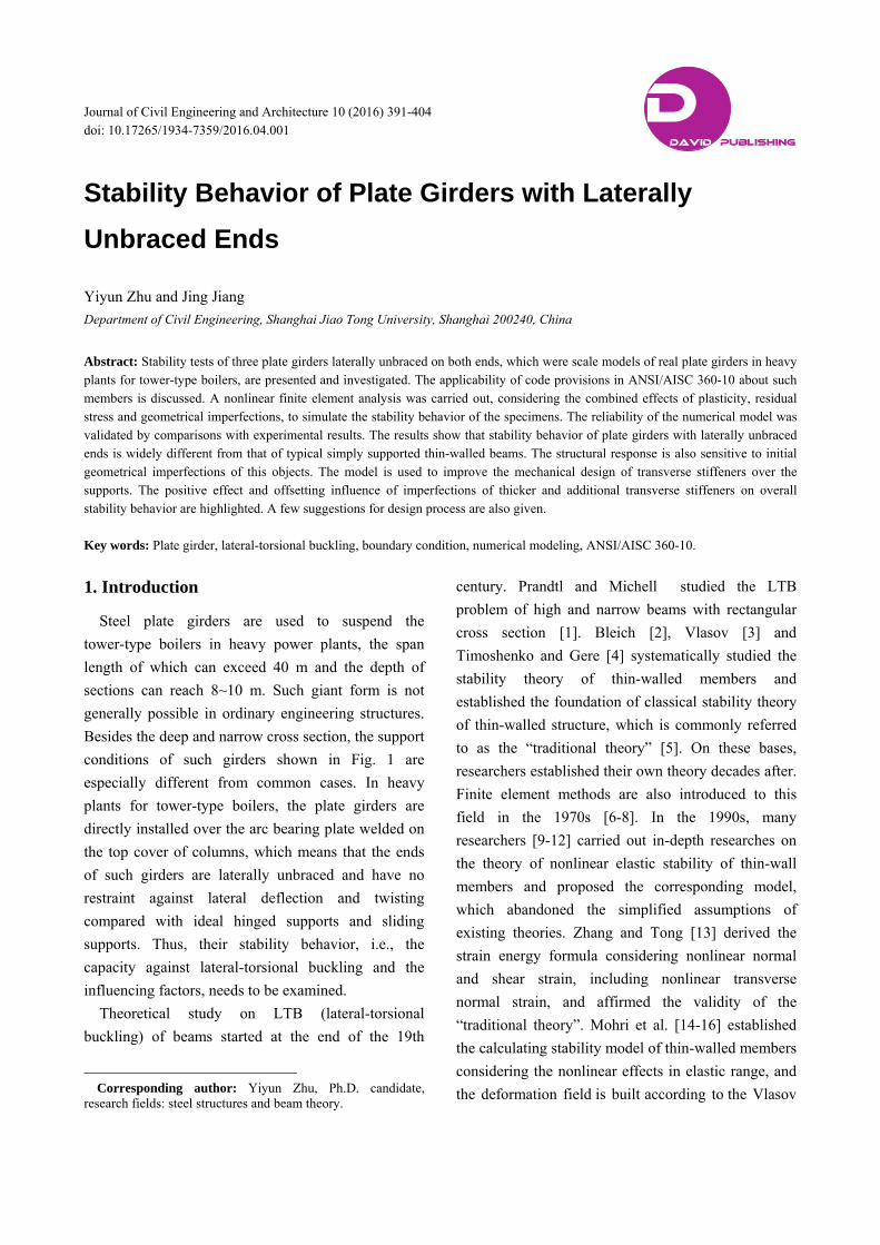
conditions of such girders shown in Fig. 1 are
especially different from common cases. In heavy
plants for tower-type boilers, the plate girders are
directly installed over the arc bearing plate welded on
the top cover of columns, which means that the ends
of such girders are laterally unbraced and have no
restraint against lateral deflection and twisting
compared with ideal hinged supports and sliding
supports. Thus, their stability behavior, i.e., the
capacity against lateral-torsional buckling and the
influencing factors, needs to be examined.
Theoretical study on LTB (lateral-torsional
buckling) of beams started at the end of the 19th
Corresponding author: Yiyun Zhu, Ph.D. candidate,
research fields: steel structures and beam theory.
century. Prandtl and Michell studied the LTB
problem of high and narrow beams with rectangular
cross section [1]. Bleich [2], Vlasov [3] and
Timoshenko and Gere [4] systematically studied the
stability theory of thin-walled members and
established the foundation of classical stability theory
of thin-walled structure, which is commonly referred
to as the “traditional theory” [5]. On these bases,
researchers established their own theory decades after.
Finite element methods are also introduced to this
field in the 1970s [6-8]. In the 1990s, many
researchers [9-12] carried out in-depth researches on
the theory of nonlinear elastic stability of thin-wall
members and proposed the corresponding model,
which abandoned the simplified assumptions of
existing theories. Zhang and Tong [13] derived the
strain energy formula considering nonlinear normal
and shear strain, including nonlinear transverse
normal strain, and affirmed the validity of the
“traditional theory”. Mohri et al. [14-16] established
the calculating stability model of thin-walled members
considering the nonlinear effects in elastic range, and
the deformation field is built according to the Vlasov
D DAVID PUBLISHING
Stability Behavior of Plate Girders with Laterally Unbraced Ends
392
Fig. 1 Support of plate girders for tower-type boilers.
assumptions, considering the nonlinear strain tensor.
Some discussions on design concepts about LTB
can be found in literatures in recent years.
Suryoatmono and Ho [17] researched on the moment
modification factor of simply supported beams,
corrected the calculating formulas of equivalent
bending moment provided by American National
Standard ANSI/AISC 360-10 [18] when the moment
is not in a linear variation. Lim et al. [19] studied on
the elastic LTB of I-shaped steel beam under different
proportions of end moments with varied end
constraints, and the improved formula they gave has
smaller error than those of ANSI/AISC 360-10 [18]
and SSRC (Structural Stability Research Council)
Guide [20]. Trahair and Hancock [21] derived a
simplified method to calculate the out of plane failure
of steel members, and the critical loads they reached
on simply supported beam under four kinds of loading
and fixed beam under a bending moment are a little
higher than AS4100-1998 [22]. Kumar and
Samanta [23, 24] used ABAQUS [25] to simulate the
overall stability of simply supported beams under
different loading, finding the SSRC Guide [20]
overestimated the critical buckling load of short
beams, which is generally controlled by torsion of
web plates. With the development of testing and
simulation technology, full-scale tests on plate girders
and corresponding nonlinear finite element analysis
with actual imperfections are performed by
researchers, while most attention has been put on
moment-shear interaction, local-global interactive
buckling and post buckling performance of the
girders.
Almost all the practical researches on stability
behavior of plate girders are based on the premise that
the objects are laterally restrained along the span or on
both support ends at least. As for the related
specifications, ANSI/AISC 360-10 has no specific
provisions for short deep flexural members laterally
unbraced along the span. This research is to get an
insight into the stability behavior of such members
and its influencing factors, provide a simple FE (finite
element) model and discuss on the applicability of
code provisions. Stability test and numerical study
indicate that the existing standards can barely guide
the design process of such girders. Moreover, the
initial geometrical imperfections, which are
commonly ignored by code provisions, may reduce
the bearing capacity in such cases and even lead to
unexpected failure.
2. Design Concepts in ANSI/AISC 360-10
2.1 Basic Equation of Buckling Moment
According to the elastic stability theory, the
buckling moment of simply supported thin-walled
beams subjected to transverse loads (Mcr) can be
expressed as following [26]:
yy
cr CaCl
EICM 322
2
1
π
wy
wy EI
GJl
I
ICaC
2
2
32 π1 (1)
where, E, G are Young’s modulus and shear modulus,
respectively, Iy is the second moment of area about
weak axis, J is St.Venant constant, Iω is warping
inertia moment, a is vertical distance between loading
point and shear centre, βy is dissymmetry coefficient.
The three factors (C1, C2, C3) are related to form and
position of transverse loads and can be derived from
the total potential energy equation of the “traditional
theory”.
Stability Behavior of Plate Girders with Laterally Unbraced Ends
393
Eq. (1) is the basis of code provisions about elastic
LTB. The American National Standard [18, 20], ISO
Code [27], Eurocode 3 [28] and Chinese Code [29]
take same or very close value of C1, C2. For doubly
symmetric members (βy = 0) and C3 has no influence,
approximate elastic buckling moment can be achieved
by different codes. Pi et al. [30] and Trahair [31]
provided C1, C2 as follows:
For uniform moment, C1 = 1.00, C2 = 0;
For uniformly distributed load, C1 = 1.13,
C2 = 0.46;
For concentrated load at mid-span, C1 = 1.35,
C2 = 0.55.
Eq. (1) is obviously not suitable for practical use,
while design concepts in codes are based on
simplified methods for calculation.
2.2 Code Provisions
ANSI/AISC 360-10 supersedes Load and
Resistance Factor Design and Allowable Stress
Design, released in 2010. The case of uniform
moment along unbraced length Lb is employed as the
basic loading case in provisions about LTB.
If Lb is below the plastic limiting unbraced length
Lp, the limit state of LTB does not apply for doubly
symmetric compact I-shaped members. The bending
strength is calculated according to the section strength
in Eq. (F2-1) of the code:
n p y xM M F Z
If Lb exceeds the elastic limiting unbraced length Lr,
the elastic LTB governs. The bending strength in this
case is given by Eq. (F2-3):
n cr x pM F S M
Then, if Lp < Lb ≤ Lr, the limit state is inelastic
failure. The nominal flexural strength is the result
of linear interpolation between section strength
and the limit state of yielding, read from Eq. (F2-2):
0.7 b pn b p p y x p
r p
L LM C M M F S M
L L
where, F2-1, F2-3, F2-2 are labels in the AISC 360-10
Code [18].
The moment modification factor Cb should be
applied when the moment distribution is nonuniform.
Limiting unbraced length Lp and Lr are calculated
according to the section parameters.
2.3 Applicability Discussions
Code provisions of ANSI/AISC 360-10 have
explicit physical meanings and simply explain the
influence of moment distribution (Cb) and residual
stress (Fr) to its users.
There is a basic assumption in design process that
the members are ideally restrained against twisting
and lateral deflection on support ends to meet the
boundary conditions of design concepts, so unbraced
length Lb equals the span length for ideal simply
supported beams. There are no specific provisions for
flexural members with laterally unbraced ends.
The geometrical size of cross sections is neglected
in the basic mechanical model, so the height of load
application points does not appear in the equations. It
can be acceptable for slender members, but not
suitable for the objects discussed in this paper.
Most of all, the initial geometrical imperfection is
ignored in the equations, because it makes very
limited difference in common circumstances and is
difficult to measure. But when it comes to plate
girders with laterally unbraced ends, combined with
high load application points, geometrical imperfection
may significantly affect the states.
3. Experimental Design
3.1 Material and Girder Description
Three girders were fabricated from two different
steel plates with Q235 (nominal yielding stress is
235 MPa) structural steel, which were 12 mm thick
for flange plates and 4 mm for web and stiffeners. The
real properties of materials were measured by simple
tension tests. For the purpose of numerical simulations,
the measured stress-strain curve was modelled with a
Stability Behavior of Plate Girders with Laterally Unbraced Ends
394
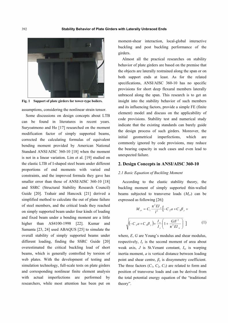
Fig. 2 Test specimens and dimensions (unit: mm).
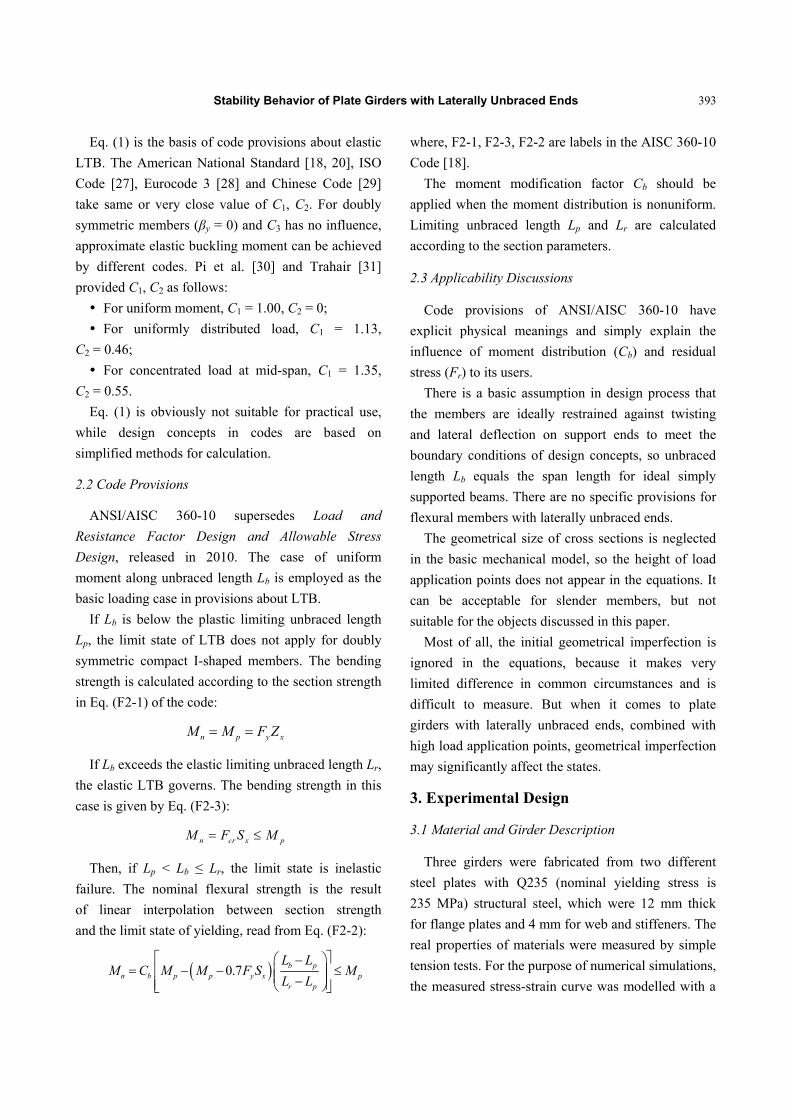
Fig. 3 Sketches of load and support (unit: mm).
2-linear curve, i.e., “bilinear isotropic plasticity” to be
the constitutive models, where Young’s modulus
E = 206 GPa, tangent modulus Et = 6,100 MPa, yield
stress Fy = 265 MPa.
The tested girders shown in Fig. 2 were scale models
of real plate girders, simplified in mechanical design.
The tested girders had total length of 3,000 mm and
span length of 2,800 mm (100-mm extension was
given on each side). The cross sections of three
specimens were the same, where h = 560, tw = 4,
bf = 120, tf = 12 mm, and 4-mm-thick transverse
stiffeners were located on every one-fifth point of the
span and both ends. The arrangements of 4-mm-thick
longitudinal stiffeners were the only difference
between three specimens.
SJ-1 had no longitudinal stiffener whereas the
specimens SJ-2 and SJ-3 had longitudinal stiffeners.
Specifically, the vertical distance from compression
flange in SJ-2 and SJ-3 were 98 mm and 288 mm,
respectively. Stiffeners can enhance the capacity of
girders, but are neglected in code provisions about
LTB.
3.2 Load and Support
A sketch of load and support conditions is shown in
Fig. 3. The load P was applied from a hydraulic jack
and was distributed into four even transverse loads
(P/4 each) on one-fifth points of the span, using rigid
distribution beam. Stress concentration is prevented
by transverse stiffeners and rigid plate on loading
points. It is obvious that vertical support reaction on
each side was P/2.
In heavy plants for tower-type boiler, loads from
the boiler are applied from hanger rods to the girders
and are commonly simplified as concentrated loads
over compression flange in design and research
process [32]. Supports of single girder were made of
an equilateral web angle and a round bar, respectively,
without any restraint against twisting and lateral
deflection along the whole span of the girder, to
simulate the actual boundary condition.
3.3 Critical Load Calculation
Plate girders are often made to be deep and narrow,
considering the economic efficiency. Thus, the local
instability and yielding of the web plates should be
taken into account.
The specimens can be classified as “doubly
symmetric I-shaped members bent about their major
axis with compact flange and noncompact web”
according to Chapter B4 of ANSI/AISC 360-10 and
should be examined according to Chapter F4. Code
provisions about such sections are similar with
compact sections introduced above, where the web
Transverse stiffener
Longitudinal stiffener of SJ-2
Longitudinal stiffener of SJ-3
P
Stability Behavior of Plate Girders with Laterally Unbraced Ends
395
plastification factor Rpc is additionally included.
According to the provisions of ANSI/AISC 360-10,
which is a simplified form of Eq. (1) and the unbraced
length is supposed to be 2,800 mm, the critical load
that the specimens can bear is: 2,800
,cr AISCP = 492.6 kN (2)
As discussed in Section 2.3, the code can not
provide authentic results for plate girders with
laterally unbraced ends, the critical load acquired
above is for reference only.
3.4 Discussions
There are no provisions about the design and
stress/buckling calculation of transverse stiffeners in
ANSI/AISC 360-10. For plate girders without any
lateral restraint along the span, the resisting force
against twist of the cross sections can only be
provided by bending stiffness of the transverse
stiffeners and that may not be enough in this case,
especially for transverse stiffeners over the supports,
which bear the largest compression, bending and
torsion loads, and may cause serious consequences if
a single piece of them is wrecked. The twist of the
cross sections on support plan will break the basic
assumption of boundary condition.
Rules to cover incomplete end restraint are available
in some codes, such as British Standard
BS5950-1:2000 [33], in which the calculating length of
such beam is its span length plus two times the height.
Those provisions can be adopted in design process. In
this case, the unbraced length Lb = 3,920 mm, and it
exceeds the elastic limiting unbraced length Lr, so the
elastic LTB governs in this case.
So, the suggested critical load is:
3 20,,9
cr AISCP = 345.5 kN (3)
which becomes much lower.
3.5 Instrumentation
Loading and measuring facilities were set up as
shown in Fig. 4. A block of stone sat beside to prevent
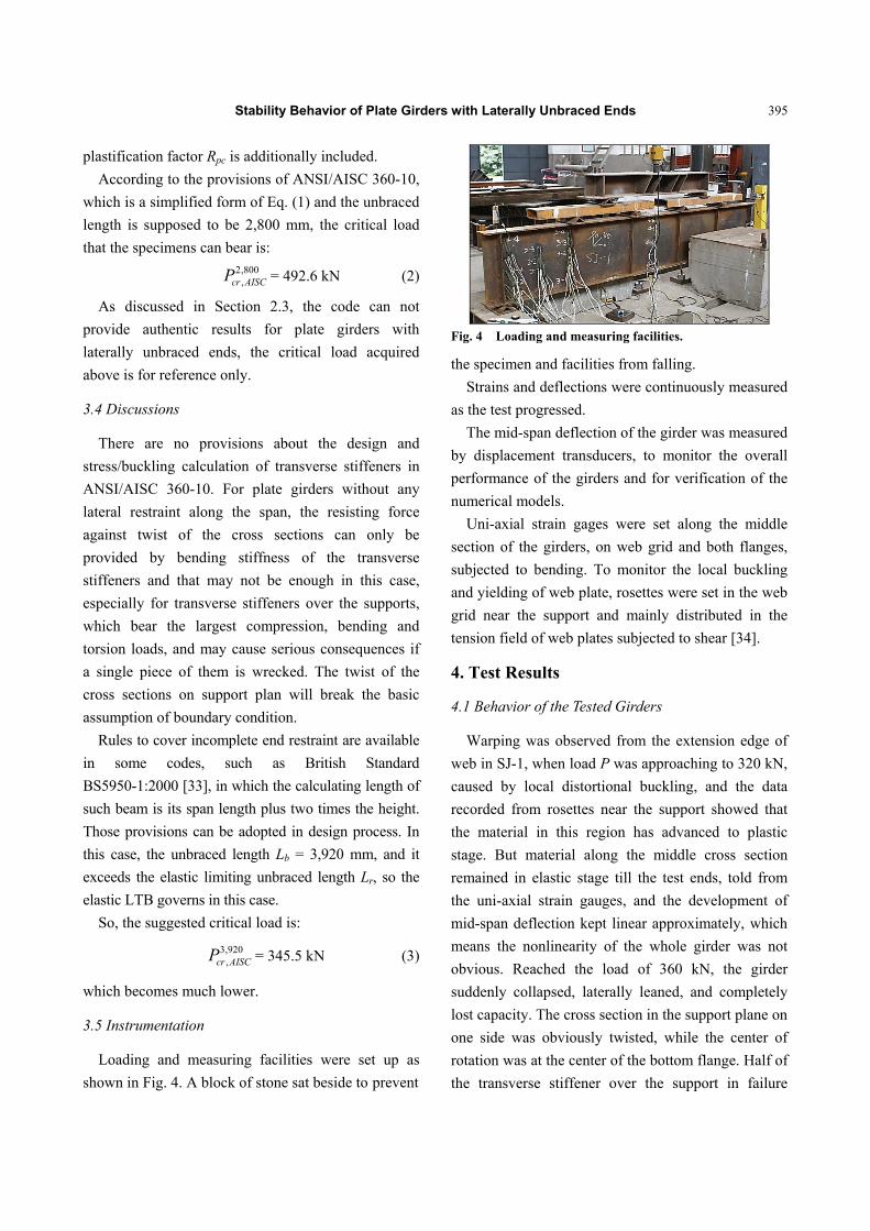
Fig. 4 Loading and measuring facilities.
the specimen and facilities from falling.
Strains and deflections were continuously measured
as the test progressed.
The mid-span deflection of the girder was measured
by displacement transducers, to monitor the overall
performance of the girders and for verification of the
numerical models.
Uni-axial strain gages were set along the middle
section of the girders, on web grid and both flanges,
subjected to bending. To monitor the local buckling
and yielding of web plate, rosettes were set in the web
grid near the support and mainly distributed in the
tension field of web plates subjected to shear [34].
4. Test Results
4.1 Behavior of the Tested Girders
Warping was observed from the extension edge of
web in SJ-1, when load P was approaching to 320 kN,
caused by local distortional buckling, and the data
recorded from rosettes near the support showed that
the material in this region has advanced to plastic
stage. But material along the middle cross section
remained in elastic stage till the test ends, told from
the uni-axial strain gauges, and the development of
mid-span deflection kept linear approximately, which
means the nonlinearity of the whole girder was not
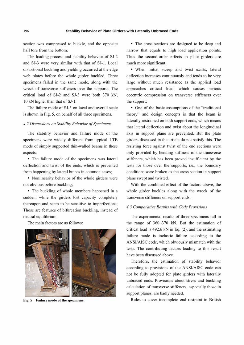
obvious. Reached the load of 360 kN, the girder
suddenly collapsed, laterally leaned, and completely
lost capacity. The cross section in the support plane on
one side was obviously twisted, while the center of
rotation was at the center of the bottom flange. Half of
the transverse stiffener over the support in failure
Stability Behavior of Plate Girders with Laterally Unbraced Ends
396
section was compressed to buckle, and the opposite
half tore from the bottom.
The loading process and stability behavior of SJ-2
and SJ-3 were very similar with that of SJ-1. Local
distortional buckling and yielding occurred at the edge
web plates before the whole girder buckled. Three
specimens failed in the same mode, along with the
wreck of transverse stiffeners over the supports. The
critical load of SJ-2 and SJ-3 were both 370 kN,
10 kN higher than that of SJ-1.
The failure mode of SJ-3 on local and overall scale
is shown in Fig. 5, on behalf of all three specimens.
4.2 Discussions on Stability Behavior of Specimens
The stability behavior and failure mode of the
specimens were widely different from typical LTB
mode of simply supported thin-walled beams in these
aspects:
The failure mode of the specimens was lateral
deflection and twist of the ends, which is prevented
from happening by lateral braces in common cases;
Nonlinearity behavior of the whole girders were
not obvious before buckling;
The buckling of whole members happened in a
sudden, while the girders lost capacity completely
thereupon and seem to be sensitive to imperfections;
Those are features of bifurcation buckling, instead of
neutral equilibrium.
The main factors are as follows:
Fig. 5 Failure mode of the specimens.
The cross sections are designed to be deep and
narrow that equals to high load application points.
Thus the second-order effects in plate girders are
much more significant;
When initial sweep and twist exists, lateral
deflection increases continuously and tends to be very
large without much resistance as the applied load
approaches critical load, which causes serious
eccentric compression on transverse stiffeners over
the support;
One of the basic assumptions of the “traditional
theory” and design concepts is that the beam is
laterally restrained on both support ends, which means
that lateral deflection and twist about the longitudinal
axis in support plane are prevented. But the plate
girders discussed in the article do not satisfy this. The
resisting force against twist of the end sections were
only provided by bending stiffness of the transverse
stiffeners, which has been proved insufficient by the
tests for those over the supports, i.e., the boundary
conditions were broken as the cross section in support
plane swept and twisted.
With the combined effect of the factors above, the
whole girder buckles along with the wreck of the
transverse stiffeners on support ends.
4.3 Comparative Results with Code Provisions
The experimental results of three specimens fall in
the range of 360~370 kN. But the estimation of
critical load is 492.6 kN in Eq. (2), and the estimating
failure mode is inelastic failure according to the
ANSI/AISC code, which obviously mismatch with the
tests. The contributing factors leading to this result
have been discussed above.
Therefore, the estimation of stability behavior
according to provisions of the ANSI/AISC code can
not be fully adopted for plate girders with laterally
unbraced ends. Provisions about stress and buckling
calculation of transverse stiffeners, especially those in
support planes, are badly needed.
Rules to cover incomplete end restraint in British
Stability Behavior of Plate Girders with Laterally Unbraced Ends
397
Standard have been adopted in design process, and the
estimation was adjusted to 345.5 kN in Eq. (3), and
the estimating failure mode is elastic LTB, which
seems to be more reasonable.
5. Numerical Simulations
A nonlinear finite element analysis was carried out
using commercial FEA (finite element analysis)
software ANSYS 14.5 [35]. The combined effects of
plasticity, residual stress and geometrical
imperfections are considered to explain the
experimental phenomena.
5.1 General
The nonlinear FE model is established by following
steps:
(1) Build an ideal model with shell elements, mesh
the flange plates and web plates before stiffeners, to
ensure that the element number of the cross section
starts from 1. Then, run the macro file to generate the
initial residual stress data on cross section;
(2) Build the same model as Step (1), and proceed
EBA (eigenvalue buckling analysis);
(3) Build the model for the third time, then apply the
initial imperfections, read the first-order buckling mode
from Step (2) to generate the shape of initial
geometrical imperfections, set 1/1,000 of total length
(3,000/1,000 mm) as the maximum amplitude,
according to the Chinese code for acceptance of
constructional quality of steel structures GB50205 [36],
and constrain all the degrees of freedom of nodes to
apply the residual stresses model with no strain;
(4) Apply real boundary conditions and loads to
proceed the nonlinear stability analysis.
5.2 FE Modeling
The shell element model proposed by Zhang and
Tong [37] is used, as less assumptions are adopted in
shell theory than beam theory, to get more precise
results. Element type SHELL 181 is used for flanges
and webs, which is a kind of four node elements with
six degrees of freedom for each node, and applicable
to nonlinear analysis with large deformation.
Transversal displacements about x- and y-axis of
nodes in supported positions on tension flange are
restrained, in addition, the rigid body motion of beam
in z-direction (longitudinal) is prevented by fixing the
z-displacement of nodes on one side. These treatments
in shell element modeling can satisfy the real
boundary condition of the specimens in experimental
tests. The maximum element width is 40 mm. The
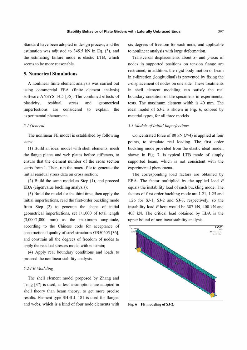
ideal model of SJ-2 is shown in Fig. 6, colored by
material types, for all three models.
5.3 Models of Initial Imperfections
Concentrated force of 80 kN (P/4) is applied at four
points, to simulate real loading. The first order
buckling mode provided from the elastic ideal model,
shown in Fig. 7, is typical LTB mode of simply
supported beam, which is not consistent with the
experimental phenomena.
The corresponding load factors are obtained by
EBA. The factor multiplied by the applied load P
equals the instability load of such buckling mode. The
factors of first order buckling mode are 1.21, 1.25 and
1.26 for SJ-1, SJ-2 and SJ-3, respectively, so the
instability load P here would be 387 kN, 400 kN and
403 kN. The critical load obtained by EBA is the
upper bound of nonlinear stability analysis.
Fig. 6 FE modeling of SJ-2.
Stability Behavior of Plate Girders with Laterally Unbraced Ends
398
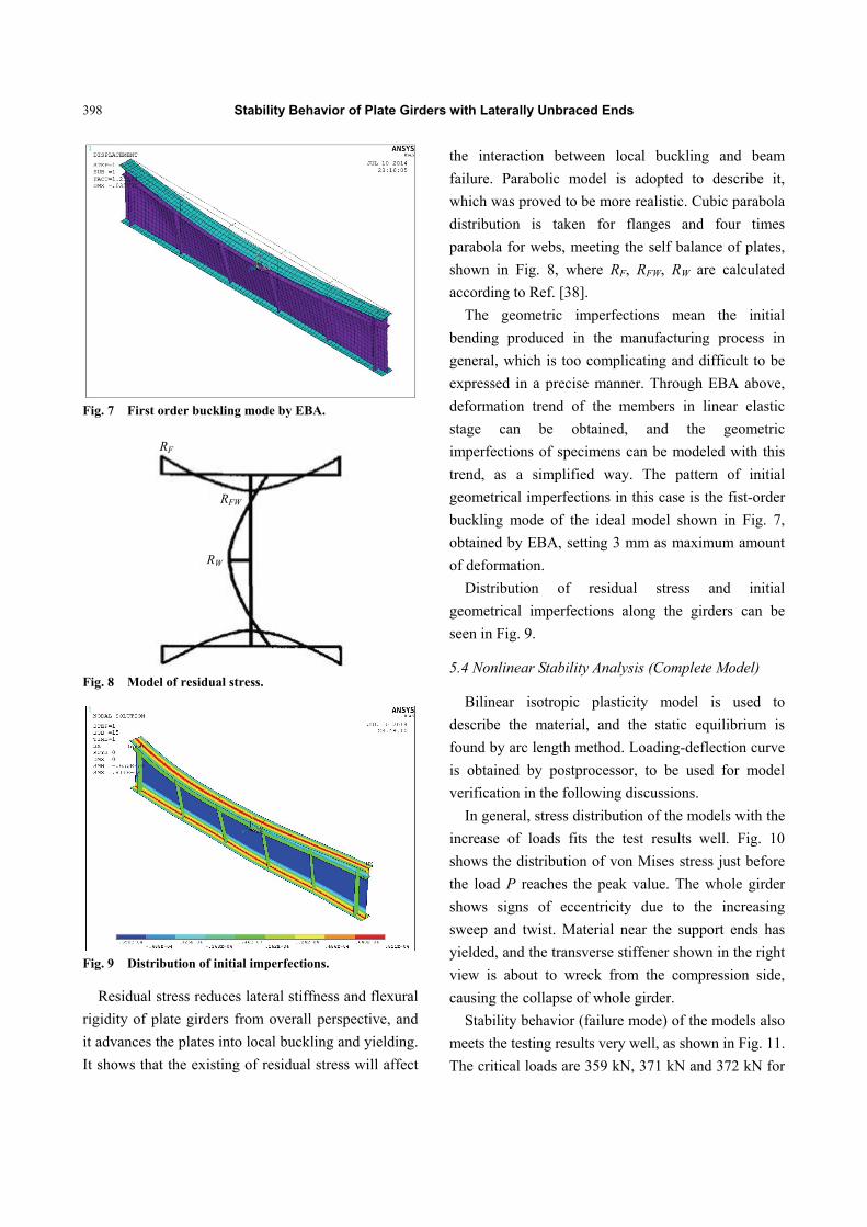
Fig. 7 First order buckling mode by EBA.
Fig. 8 Model of residual stress.
Fig. 9 Distribution of initial imperfections.
Residual stress reduces lateral stiffness and flexural
rigidity of plate girders from overall perspective, and
it advances the plates into local buckling and yielding.
It shows that the existing of residual stress will affect
the interaction between local buckling and beam
failure. Parabolic model is adopted to describe it,
which was proved to be more realistic. Cubic parabola
distribution is taken for flanges and four times
parabola for webs, meeting the self balance of plates,
shown in Fig. 8, where RF, RFW, RW are calculated
according to Ref. [38].
The geometric imperfections mean the initial
bending produced in the manufacturing process in
general, which is too complicating and difficult to be
expressed in a precise manner. Through EBA above,
deformation trend of the members in linear elastic
stage can be obtained, and the geometric
imperfections of specimens can be modeled with this
trend, as a simplified way. The pattern of initial
geometrical imperfections in this case is the fist-order
buckling mode of the ideal model shown in Fig. 7,
obtained by EBA, setting 3 mm as maximum amount
of deformation.
Distribution of residual stress and initial
geometrical imperfections along the girders can be
seen in Fig. 9.
5.4 Nonlinear Stability Analysis (Complete Model)
Bilinear isotropic plasticity model is used to
describe the material, and the static equilibrium is
found by arc length method. Loading-deflection curve
is obtained by postprocessor, to be used for model
verification in the following discussions.
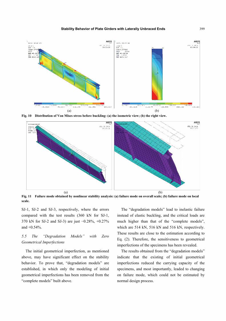
In general, stress distribution of the models with the
increase of loads fits the test results well. Fig. 10
shows the distribution of von Mises stress just before
the load P reaches the peak value. The whole girder
shows signs of eccentricity due to the increasing
sweep and twist. Material near the support ends has
yielded, and the transverse stiffener shown in the right
view is about to wreck from the compression side,
causing the collapse of whole girder.
Stability behavior (failure mode) of the models also
meets the testing results very well, as shown in Fig. 11.
The critical loads are 359 kN, 371 kN and 372 kN for
RF
RFW
RW
Stability Behavior of Plate Girders with Laterally Unbraced Ends
399
(a) (b)
Fig. 10 Distribution of Von Mises stress before buckling: (a) the isometric view; (b) the right view.
(a) (b)
Fig. 11 Failure mode obtained by nonlinear stability analysis: (a) failure mode on overall scale; (b) failure mode on local scale.
SJ-1, SJ-2 and SJ-3, respectively, where the errors
compared with the test results (360 kN for SJ-1,
370 kN for SJ-2 and SJ-3) are just −0.28%, +0.27%
and +0.54%.
5.5 The “Degradation Models” with Zero
Geometrical Imperfections
The initial geometrical imperfection, as mentioned
above, may have significant effect on the stability
behavior. To prove that, “degradation models” are
established, in which only the modeling of initial
geometrical imperfections has been removed from the
“complete models” built above.
The “degradation models” lead to inelastic failure
instead of elastic buckling, and the critical loads are
much higher than that of the “complete models”,
which are 514 kN, 516 kN and 516 kN, respectively.
These results are close to the estimation according to
Eq. (2). Therefore, the sensitiveness to geometrical
imperfections of the specimens has been revealed.
The results obtained from the “degradation models”
indicate that the existing of initial geometrical
imperfections reduced the carrying capacity of the
specimens, and most importantly, leaded to changing
on failure mode, which could not be estimated by
normal design process.
Stability Behavior of Plate Girders with Laterally Unbraced Ends
400
5.6 Comparative Results and Model Verification
Results of different kind of analysis are listed in
Table 1, to make the standpoints clear.
The “complete model”, for nonlinear finite element
stability analysis with a combined effect of plasticity,
residual stress and geometrical imperfections, is
verified by the test, and all the initial imperfections
are built with simplified model to reduce the quantity
of work. The significant effects of boundary condition
and geometrical imperfection are discussed and
proved, as well.
It can be found that, when it comes to the
interaction between local buckling and column failure
of thin-walled compression members, geometrical
imperfection becomes a major factor [39]. Obviously,
plate girders with deep sections and laterally unbraced
ends studied in this paper have similar properties.
In addition, according to the results of SJ-1,
although the longitudinal stiffeners are neglected in
code provisions, it is still suggested to be set in such
girders to enhance the stability of whole members.
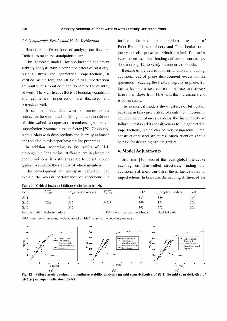
The development of mid-span deflection can
explain the overall performance of specimens. To
further illustrate the problem, results of
Euler-Bernoulli beam theory and Timoshenko beam
theory are also presented, which are both first order
beam theories. The loading-deflection curves are
shown in Fig. 12, to verify the numerical models.
Because of the deviation of installation and loading,
additional out of plane displacement occurs on the
specimens, reducing the flexural rigidity in plane. So,
the deflections measured from the tests are always
larger than those from FEA, and the increasing trend
is not so stable.
The numerical models show features of bifurcation
buckling in this case, instead of neutral equilibrium in
common circumstances explains the instantaneity of
failure in tests and its sensitiveness to the geometrical
imperfections, which can be very dangerous in real
constructional steel structures. Much attention should
be paid for designing of such girders.
6. Model Adjustments
Sridharan [40] studied the local-global interactive
buckling on thin-walled structures, finding that
additional stiffeners can offset the influence of initial
imperfections. In this case, the bending stiffness of the
Table 1 Critical loads and failure mode (units in kN).
Item 2 00,,8
cr AISCP Degradation models 3 20,,9
cr AISCP EBA Complete models Tests
SJ-1
492.6
514
345.5
387 359 360
SJ-2 516 400 371 370
SJ-3 516 403 372 370
Failure mode Inelastic failure LTB (lateral-torsional buckling) Buckled ends
EBA: First order buckling mode obtained by EBA (eigenvalue buckling analysis).
(a) (b) (c)
Fig. 12 Failure mode obtained by nonlinear stability analysis: (a) mid-span deflection of SJ-1; (b) mid-span deflection of SJ-2; (c) mid-span deflection of SJ-3.
Euler-Bernoulli Timoshenko Complete model Degradation model Experiment
Euler-Bernoulli Timoshenko Complete model Degradation model Experiment
Euler-Bernoulli Timoshenko Complete model Degradation model Experiment
v (mm) v (mm) v (mm)
P (
kN)
P (
kN)
P (
kN)
Stability Behavior of Plate Girders with Laterally Unbraced Ends
401
(a) (b) (c)
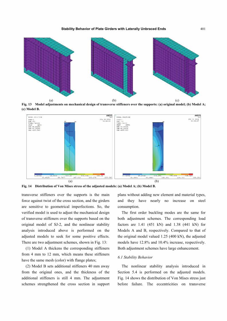
Fig. 13 Model adjustments on mechanical design of transverse stiffeners over the supports: (a) original model; (b) Model A; (c) Model B.
(a) (b)
Fig. 14 Distribution of Von Mises stress of the adjusted models: (a) Model A; (b) Model B.
transverse stiffeners over the supports is the main
force against twist of the cross section, and the girders
are sensitive to geometrical imperfections. So, the
verified model is used to adjust the mechanical design
of transverse stiffeners over the supports based on the
original model of SJ-2, and the nonlinear stability
analysis introduced above is performed on the
adjusted models to seek for some positive effects.
There are two adjustment schemes, shown in Fig. 13:
(1) Model A thickens the corresponding stiffeners
from 4 mm to 12 mm, which means these stiffeners
have the same mesh (color) with flange plates;
(2) Model B sets additional stiffeners 40 mm away
from the original ones, and the thickness of the
additional stiffeners is still 4 mm. The adjustment
schemes strengthened the cross section in support
plans without adding new element and material types,
and they have nearly no increase on steel
consumption.
The first order buckling modes are the same for
both adjustment schemes. The corresponding load
factors are 1.41 (451 kN) and 1.38 (441 kN) for
Models A and B, respectively. Compared to that of
the original model valued 1.25 (400 kN), the adjusted
models have 12.8% and 10.4% increase, respectively.
Both adjustment schemes have large enhancement.
6.1 Stability Behavior
The nonlinear stability analysis introduced in
Section 5.4 is performed on the adjusted models.
Fig. 14 shows the distribution of Von Mises stress just
before failure. The eccentricities on transverse
Stability Behavior of Plate Girders with Laterally Unbraced Ends
402
stiffeners over the supports are greatly decreased and
far from wreck compared to the situation shown in
Fig. 10, which means that the effect of geometrical
imperfections has been offset to some extent.
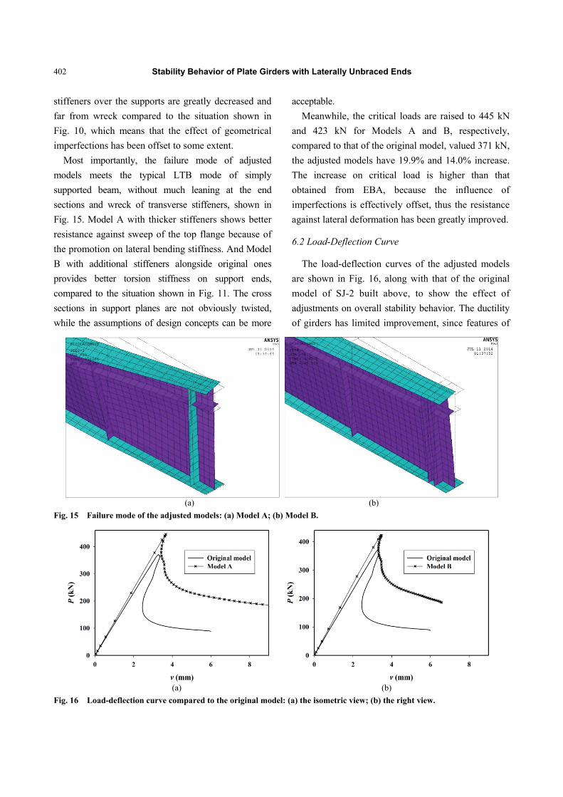
Most importantly, the failure mode of adjusted
models meets the typical LTB mode of simply
supported beam, without much leaning at the end
sections and wreck of transverse stiffeners, shown in
Fig. 15. Model A with thicker stiffeners shows better
resistance against sweep of the top flange because of
the promotion on lateral bending stiffness. And Model
B with additional stiffeners alongside original ones
provides better torsion stiffness on support ends,
compared to the situation shown in Fig. 11. The cross
sections in support planes are not obviously twisted,
while the assumptions of design concepts can be more
acceptable.
Meanwhile, the critical loads are raised to 445 kN
and 423 kN for Models A and B, respectively,
compared to that of the original model, valued 371 kN,
the adjusted models have 19.9% and 14.0% increase.
The increase on critical load is higher than that
obtained from EBA, because the influence of
imperfections is effectively offset, thus the resistance
against lateral deformation has been greatly improved.
6.2 Load-Deflection Curve
The load-deflection curves of the adjusted models
are shown in Fig. 16, along with that of the original
model of SJ-2 built above, to show the effect of
adjustments on overall stability behavior. The ductility
of girders has limited improvement, since features of
(a) (b)
Fig. 15 Failure mode of the adjusted models: (a) Model A; (b) Model B.
(a) (b)
Fig. 16 Load-deflection curve compared to the original model: (a) the isometric view; (b) the right view.
Stability Behavior of Plate Girders with Laterally Unbraced Ends
403
bifurcation buckling are inevitable once initial
geometrical imperfections are considered. The failure
of the girders will still be instantaneous.
6.3 Effect of Adjustments
The adjustments on mechanical design of transverse
stiffeners over the supports have very positive effect
on resistance against lateral deformation, especially on
support ends of the girders, and they greatly enhance
the overall bearing capacity. Thicker and additional
transverse stiffeners can effectively offset the
influence of initial geometrical imperfections locally
in stiffened regions. Thus, the rigid frame assumption
and assumption on boundary conditions of ideal
simply supported thin-walled beam adopted by the
“traditional theory” and design concepts can be better
satisfied, to make the code provisions more applicable
on the objects.
7. Conclusions
Tests were performed to get an insight into the
stability behavior of plate girders with laterally
unbraced ends and its influencing factors. A simple
numerical model was defined to build and fit well
with the experimental results.
Lacking of lateral restraint, especially on support
ends, interacts with high load application points and
geometrical imperfections. They can significantly
reduce the carrying capacity of plate girders and even
lead to instant and complete failure from support ends.
If the girders have to be designed so, some additional
suggestions can be provided:
The deflection calculated through first order
theories should be amplified;
Real beams are not perfectly straight, so the
design bending strength should have enough safety
margin for those imperfections;
Although the stiffeners are neglected in code
provisions about LTB, they are still suggested to be
well set in such girders because they have big effects
actually;
Rules to cover incomplete end restraint are
available in some codes. Those provisions can be
adopted in design process;
Thicker and additional transverse stiffeners at the
edge of girders can provide better resistance against
lateral deformation and effectively offset the influence
of imperfections.
8. Research Expectations
The research should be extended to monosymmetric
sections, T-sections, etc., and other load conditions
should be studied. With a wide set of specimens,
computational and statistical analyses will be
performed to achieve reliable conclusions and to give
design proposals about stability behavior of giant
plate girders under various loading with any boundary
conditions.
Acknowledgments
The authors gratefully acknowledge sponsors of
this research: National Science Foundation of China
(No. 51278296).
References
[1] Kosmatka, J. B. 1993. “Flexure-Torsion Behavior of Prismatic Beams. I-Section Properties via Power Series.” AIAA (American Institute of Aeronautics and Astronautics) Journal 31 (1): 170-9.
[2] Bleich, F. 1952. Buckling Strength of Metal Structures. New York: McGraw-Hill Book Co.
[3] Vlasov, V. Z. 1961. Thin-Walled Elastic Beams. 2nd ed. Washington, D.C.: National Science Foundation.
[4] Timoshenko, S. P., and Gere, J. M. 1961. Theory of Elastic Stability. 2nd ed. New York: McGraw-Hill Book Co.
[5] Tong, G., and Zhang, L. 2003. “An Analysis of Current Stability Theories for Thin-Walled Members.” Advances in Structural Engineering 6 (4): 283-92.
[6] Johnson, C. P., and Will, K. M. 1974. “Beam Buckling by Finite Element Procedure.” Journal of the Structural Division 100 (3): 669-85.
[7] Nethercot, D. A. 1975. “Inelastic Buckling of Steel Beams under Non-uniform Moment.” Structural Engineering 53 (2): 73-8.
[8] Nethercot, D. A., and Trahair, N. S. 1976. “Inelastic Lateral Buckling of Determinate Beams.” Journal of the
Stability Behavior of Plate Girders with Laterally Unbraced Ends
404
Structural Division 102 (4): 701-17. [9] Trahair, N. S., and Bild, S. 1990. “Elastic Biaxial
Bending and Torsion of Thin-Walled Members.” Thin-Walled Structure 9: 269-307.
[10] Pi, Y. L., and Trahair, N. S. 1992. “Prebuckling Deflections and Lateral Buckling. I: Theory.” J. Struct. Eng. ASCE 118 (11): 2949-66.
[11] Pi, Y. L., and Trahair, N. S. 1992. “Prebuckling Deflections and Lateral Buckling. II: Applications.” J. Struct. Eng. ASCE 118 (11): 2967-85.
[12] Trahair, N. S. 1996. “Laterally Unsupported Beams.” Engineering Structures 18 (10): 759-68.
[13] Zhang, L., and Tong, G. S. 2004. “Flexural–Torsional Buckling of Thin-Walled Beam Members Based on Shell Buckling Theory.” Thin-Walled Structures 42 (12): 1665-87.
[14] Mohri, F., Azrar, L., and Potier-Ferry, M. 2001.
“Flexural-Torsional Post-buckling Analysis of
Thin-Walled Elements with Open Sections.” Thin-Walled
Structures 39: 907-38.
[15] Mohri, F., Azrar, L., and Potier-Ferry, M. 2002. “Lateral
Post-buckling Analysis of Thin-Walled Open Section
Beams.” Thin-Walled Structures 40: 1013-36.
[16] Mohri, F., Brouki, A., and Roth, J. C. 2003. “Theoretical and Numerical Stability of Unrestrained, Mono-symmetric Thin-Walled Beams.” Journal of Constructional Steel Research 59: 63-90.
[17] Suryoatmono, B., and Ho, D. 2002. “The Moment Gradient Factor in Lateral-Torsional Buckling on Wide Flange Steel Sections.” Journal of Constructional Steel Research 58: 1247-64.
[18] AISC (American Institute of Steel Construction, Inc.).
2010. ANSI A. AISC 360-10, Specification for Structural
Steel Buildings. Chicago: AISC.
[19] Lim, N. H., Park, N. H., Kang, Y. J., and Sung, I. H. 2003. “Elastic Buckling of I-Beams under Linear Moment Gradient.” International Journal of Solids and Structures 40: 5635-47.
[20] Galambos, T. V. 1998. Guide to Stability Design Criteria for Metal Structures. Hoboken: John Wiley & Sons.
[21] Trahair, N. S., and Hancock, G. J. 2004. “Steel Member
Strength by Inelastic Lateral Buckling.” Journal of
Structural Engineering 130 (1): 64-9.
[22] Standard Australia. 1998. AS4100-1998: Steel Structures. Sydney: Standard Australia.
[23] Kumar, A., and Samanta, A. 2006. “Distortional Buckling in Monosymmetric I-Beams.” Thin-Walled Structures 44: 51-6.
[24] Kumar, A., and Samanta, A. 2006. “Distortional Buckling
in Monosymmetric I-Beams: Reverse-Curvature Bending.” Thin-Walled Structures 44: 721-5.
[25] Hibbitt, Karlsson and Sorensen, Inc. 2001. ABAQUS/Standard User’s Manual. Vol. 1. Providence: Hibbitt, Karlsson and Sorensen, Inc.
[26] Chen, J. 2003. Stability of Steel Structures Theory and Design. Beijing: Science Press. (in Chinese)
[27] ISO (International Organization for Standardization). 1996. ISO/TV147, Steel Structures, Material and Design. Geneva: ISO.
[28] CEN (European Committee for Standardization). 1992. Eurocode 3: Design of Steel Structures: Part 1-1: General Rules and Rules for Buildings. Brussels: CEN.
[29] Ministry of Construction of the People’s Republic of China. 2003. GB 50017-2003 Code for Design of Steel Structures. Beijing: China Planning Press.
[30] Pi, Y. L., Trahair, N. S., and Rajasekaran, S. 1992. “Energy Equation for Beam Lateral Buckling.” Journal of Structural Engineering 118 (6): 1462-79.
[31] Trahair, N. S. 1993. Flexural-Torsional Buckling of Structures. London: E&FN Spon.
[32] Evans, H. R., and Moussef, S. 1988. “Design Aid for Plate Girders.” Proceedings of the Institution of Civil Engineers 85 (1): 89-104.
[33] British Standards. BS 5950-1:2000—Structural Use of
Steelwork in Building—Part 1. London: British Standards. [34] Basier, K. 1961. “Strength of Plate Girders under
Combined Bending and Shear.” In American Society of Civil Engineers Proceedings, Vol. 87. Virginia: American Society of Civil Engineers.
[35] ANSYS, Inc. 2013. Structural Analysis Guide. Pennsylvania: ANSYS Inc.
[36] National Standard of the People’s Republic of China. 2001. GB 50205: Code for Acceptance of Construction Quality of Steel Structures. Beijing: National Standard of the People’s Republic of China.
[37] Zhang, L., and Tong, G. S. 2008. “Lateral Buckling of Web-Tapered I-Beams: A New Theory.” Journal of Constructional Steel Research 64 (12): 1379-93.
[38] Huber, A. W., and Beedle, L. S. 1953. Residual Stress
and the Compressive Strength of Steel. Technical report of Fritz Engineering Laboratory, Lehigh
University, Bethlehem. [39] Van der Neut, A. 1969. The Interaction of Local Buckling
and Column Failure of Thin-Walled Compression Members. Berlin: Springer.
[40] Sridharan, S. 1977. “Elastic Postbuckling Behaviour and Crinkly Collapse of Plate Structures.” Ph.D. thesis, University of Southampton.