st-13 argos satellite transmitter instruction...
TRANSCRIPT

ST-13 ARGOS SATELLITE TRANSMITTERINSTRUCTION MANUAL
4/99
COPYRIGHT (c) 1999 CAMPBELL SCIENTIFIC, INC.

WARRANTY AND ASSISTANCE
The ST-13 TRANSMITTER AND SDC99 INTERFACE are warranted by CAMPBELL SCIENTIFIC, INC. tobe free from defects in materials and workmanship under normal use and service for twelve (12) monthsfrom date of shipment unless specified otherwise. Batteries have no warranty. CAMPBELL SCIENTIFIC,INC.'s obligation under this warranty is limited to repairing or replacing (at CAMPBELL SCIENTIFIC,INC.'s option) defective products. The customer shall assume all costs of removing, reinstalling, andshipping defective products to CAMPBELL SCIENTIFIC, INC. CAMPBELL SCIENTIFIC, INC. will returnsuch products by surface carrier prepaid. This warranty shall not apply to any CAMPBELL SCIENTIFIC,INC. products which have been subjected to modification, misuse, neglect, accidents of nature, orshipping damage. This warranty is in lieu of all other warranties, expressed or implied, includingwarranties of merchantability or fitness for a particular purpose. CAMPBELL SCIENTIFIC, INC. is notliable for special, indirect, incidental, or consequential damages.
Products may not be returned without prior authorization. To obtain a Returned Materials Authorization(RMA), contact CAMPBELL SCIENTIFIC, INC., phone (435) 753-2342. After an applications engineerdetermines the nature of the problem, an RMA number will be issued. Please write this number clearly onthe outside of the shipping container. CAMPBELL SCIENTIFIC's shipping address is:
CAMPBELL SCIENTIFIC, INC.RMA#_____815 West 1800 NorthLogan, Utah 84321-1784
CAMPBELL SCIENTIFIC, INC. does not accept collect calls.
Non-warranty products returned for repair should be accompanied by a purchase order to cover the repair.
815 W. 1800 N.Logan, UT 84321-1784USAPhone (435) 753-2342FAX (435) 750-9540www.campbellsci.com
Campbell Scientific Canada Corp.11564 -149th StreetEdmonton, Alberta T5M 1W7CANADAPhone (403) 454-2505FAX (403) 454-2655
Campbell Scientific Ltd.Campbell Park80 Hathern RoadShepshed, Leics. LE12 9RPENGLANDPhone (44)-50960-1141FAX (44)-50960-1091

i
ST-13 ARGOS SATELLITE TRANSMITTERTABLE OF CONTENTS
PAGE
1. ARGOS OVERVIEW ................................................................................................................. 1
2. SPACE SEGMENT.................................................................................................................... 1
3. USER TRANSMITTERS .......................................................................................................... 2
4. GETTING ONTO THE ARGOS SYSTEM .......................................................................... 2
5. DATA DELIVERY ...................................................................................................................... 3
6. DATALOGGER INTERFACE ................................................................................................. 3
7. DATALOGGER TO ST-13 PHYSICAL CONNECTIONS .............................................. 3
8. SDC99 MODIFICATION INFORMATION .......................................................................... 5
9. SDC99 TO ST-13 INTERFACE CABLE ............................................................................. 5
10. INSTRUCTION 121: DATA TRANSFER ANDCONTROL COMMAND TO ST-13 ................................................................................. 5
11. IMPORTANT OUTPUT ARRAY ID INFORMATION ....................................................... 6
12. TRANSMISSION CONSIDERATIONS ............................................................................... 6
13. DATA INTEGRITY ..................................................................................................................... 7
14. PROGRAMMING ALTERNATIVE A .................................................................................... 7
15. PROGRAMMING ALTERNATIVE B .................................................................................... 7
16. POWER BUDGET AND POWER SUPPLY CONSIDERATIONS .............................. 8
16.1 CR10X Based Weather Station................................................................................................. 816.2 ST-13 ARGOS Transmitter (200 Second Transmission Intervals) ........................................... 916.3 ST-13 ARGOS Transmitter (90 Second Transmission Intervals) ............................................. 916.4 Average Daily System Current Drain Calculation ...................................................................... 9
17. PROGRAMMING EXAMPLES .............................................................................................. 9

TABLE OF CONTENTS
ii
PAGE
APPENDICES
A. TELONICS ST-13 ASYNCHRONOUS SERIAL INTERFACE
A.1 Scope .....................................................................................................................................A-1A.2 Overview.................................................................................................................................A-1A.3 Serial Communication - Hardware Configuration ...................................................................A-2A.4 Electrical Interface and I/O Pin Loading .................................................................................A-3A.5 Serial Communication Protocol ..............................................................................................A-5A.6 Commanding ..........................................................................................................................A-5
A.6.1 Command Data................................................................................................................A-5A.6.2 Command Initiation ..........................................................................................................A-5A.6.3 ST-13’s Response ...........................................................................................................A-6A.6.4 Command Time-Out ........................................................................................................A-6A.6.5 Commands.......................................................................................................................A-6
A.7 ST-13 ARGOS Message Format (Uplink Message) ............................................................A-10A.7.1 Message Format Without Transmit Error Counts ..........................................................A-10A.7.2 Message Format With Transmit Error Counts ...............................................................A-12
A.8 Failsafe Mode .......................................................................................................................A-13A.8.1 Failsafe Message Format ..............................................................................................A-13
A.9 ST-13 Input/Output Connector Pinouts ................................................................................A-15A.10 Asynchronous Interface Parameters ....................................................................................A-16A.11 Timing Diagrams ..................................................................................................................A-17
B. FINAL STORAGE FORMAT ...............................................................................................B-1
FIGURES
1 ST-13 Enclosure Assembly ....................................................................................................... 4A-1 Serial I/O, TTL Termination ....................................................................................................A-4A-2 Serial I/O, RS-232 Termination ..............................................................................................A-4A-3 Message Format without Transmit Error Counts..................................................................A-11A-4 Message Format with Transmit Error Counts.......................................................................A-12A-5 FailSafe Message Format ....................................................................................................A-14A-6 ST-13 I/O Connector Pinouts ...............................................................................................A-15A-7 Transmission Timing Sequence ...........................................................................................A-17A-8 Wakeup and Character Timing Characteristics....................................................................A-18A-9 Multiple Command Timing....................................................................................................A-19

1
ST-13 ARGOS SATELLITE TRANSMITTER
1. ARGOS OVERVIEW1
Argos is a one-way satellite based location anddata collection system dedicated to monitoringand protecting the environment. The Argossystem has been operational since 1978. It wasestablished under an agreement between:
• the National Oceanic and AtmosphericAdministration (NOAA, USA)
• the National Aeronautics and SpaceAdministration (NASA, USA)
• the French Space Agency (CNES).
Argos is operated and managed by:
• Collecte, Localisation, Satellites (CLS), aCNES subsidiary in Toulouse, France
• Service Argos, Inc., a CLS subsidiary inLandover, near Washington, DC, USA
2. SPACE SEGMENT
The Argos receivers are flown on board theNational Oceanic and AtmosphericAdministration (NOAA) Polar OrbitingEnvironmental Satellites (POES) at an altitudeof 850 km. At least two satellites areoperational at any time in polar circular orbitsproviding full global coverage. Launches arescheduled through 2010.
The satellites receive the Argos messages fromuser’s transmitters (also called PlatformTransmitting Terminal (PTT)) and relay them toground in real time. They also store them ontape recorders and read out (“dump”) themessages every time they pass over one of thethree main ground stations:
• Wallops Island, Virginia, USA
• Fairbanks, Alaska, USA
• Lannion, France.
1 From Argos User Manual 1.0 January 1996
The POES satellites see the North and SouthPoles on each orbital revolution. Their orbitalplanes rotate about the polar axis at the samerate as the Earth about the sun, or onecomplete revolution per year. Each orbitalrevolution transects the equatorial plane at fixedlocal solar times. Therefore, each satellitepasses within visibility of any given transmitterat almost the same local time each day. Thetime taken to complete a revolution around theearth is approximately 102 minutes.
At any given time, each satellite simultaneously“sees” all transmitters within an approximate5000-kilometer-diameter “footprint”, or visibilitycircle. As the satellite proceeds in orbit, thevisibility circle sweeps a 5000 kilometer swatharound the Earth, covering both poles.
Due to the Earth’s rotation, the swath shifts 25o
west (2800 km at the Equator) about the polaraxis on each revolution. This results in overlapbetween successive swaths. Since overlapincreases with latitude, the number of dailypasses over a transmitter also increases withlatitude. At the poles, the satellites see eachtransmitter on every pass, a total of roughly 28times a day for two satellites (see table 1).
The duration of transmitter visibility by thesatellite (or of the pass duration over thetransmitter) is the “window” during which thesatellite can receive messages from thetransmitter. It lasts up to 14 minutes (10minutes on average).

ST-13 ARGOS SATELLITE TRANSMITTER
2
TABLE 1. Station Latitude vs. Number of Argos Satellite Passes
PTT Cumulative Minimum Number Mean Number Maximum NumberLatitude Visibility Of Passes Per Of Passes Per Of Passes Per
Over 24 Hours 24 Hours 24 Hours 24 Hours
0 degree 80 min. 6 7 8± 15 degrees 88 min. 8 8 9± 30 degrees 100 min. 8 9 12± 45 degrees 128 min. 10 11 12± 55 degrees 170 min. 16 16 18± 65 degrees 246 min. 21 22 23± 75 degrees 322 min. 28 28 28± 90 degrees 384 min. 28 28 28
3. USER TRANSMITTERS
A transmitter is any station equipped fortransmission via the Argos system. Eachtransmitter, sometimes called a PlatformTransmitter Terminal, or PTT, has an individualidentification number.
The main signal characteristics are:
• Transmit uplink frequency 401.650 MHz ±4kHz. This must remain stable, as the Argoslocation calculation (optional service) isbased on measurements of the Dopplereffect.
• Repetition period, assigned by ServiceArgos according to the application; forexample data collection transmitter aretypically assigned either 90 second or 200second intervals.
• The transmitter message includes:
• a preliminary synchronizationsequence
• statement of message length whichcan be 32 to 256 bits
• the transmitter id number
• the sensor data or other messagedata, 32 to 256 bits
• Each message lasts 360 to 920milliseconds according to the number ofmessage bits.
4. GETTING ONTO THE ARGOSSYSTEM
There is a formal application process to getonto the Argos Satellite System. There is also acharge to use the system as well. Since a radiofrequency signal is sent up to the satellite usersmust contact their national telecommunicationsauthority for authorization to use the ArgosUplink frequency. Users in the United Statesmust apply for an Federal CommunicationsCommission (FCC) license. For furtherinformation on ARGOS and the FCC visit thefollowing web sites:
FCC Information
The user must submit Application Form 442and Form 159/159-C to the FCC
To order these forms, call (800) 418-3676 oraccess their web site:
FCC Web Site: http://www.fcc.gov
ARGOS
ARGOS Web Site: http://www.argosinc.com
• For users in eastern North America
Service Argos, Inc.Suite 101801 McCormick DriveLandover, MD 20785ph# (301) 925-4411fax# (301) 925-8995E-mail: [email protected]
ST-13 ARGOS SATELLITE TRANSMITTER
3
• For users in western North America
Service Argos, Inc.4210 198th St., S.W.Suite 202Lynwood, WA 98036Tel: (+1) 206-672-4699Fax: (+1) 206-672-8926E-Mail: [email protected]
• For users in Japan
Cubic-I LtdTakeuchi Building 6f - 8 - 1 - 14Nishi GotandaShinagawa-kuTokyo 141JapanTel: (+81) 3-3779-5506Fax: (+81) 3-3779-5783E-mail: [email protected] (send via
Toulouse)
• For users in Australia or New Zealand
Bureau of MeteorologyGPO Box 1289 KMelbourne, Victoria 3001AustraliaTel: (+61) 3-9669-4650Fax: (+61) 3-9669-4675E-mail: [email protected]
• For users anywhere else in the world
CLS18 avenue Edouard-Belin31055 Toulouse CedexFranceTel: (+33) (0)5-61-394-700Fax: (+33) (0)5-61-751-014E-mail: [email protected]
5. DATA DELIVERY
Accessing your data is easy. You can retrieveyour results from anywhere in the world bypublic data networks, often within 20 minutes oftransmission. Service Argos currently offersdata delivery via email, Telnet session, and dial-in modem. Other delivery services (diskette,tape, printout, etc.) are also available.
6. DATALOGGER INTERFACE
Serial interface firmware has been written in theDatalogger Operating System to Interface to theTELONICS ST-13 ARGOS Transmitter.Current Dataloggers supported are the CR10,CR10X, CR23X, CR500, and CR510Dataloggers. The CR10 requires a LibrarySpecial EPROM to be physically installed. Thestandard CR10 Firmware does not supportcommunications between the Datalogger andST-13 Transmitter (P99). The CR10X, CR23X,CR500, and CR510 Dataloggers supports thisspecial instruction in a Flash EPROM (P121) asshipped from the factory.
This firmware interface passes commands anddata from the Datalogger to the ST-13 Buffer.Only low resolution 2-byte final storagedatalogger data is transferred over the ArgosSatellite Link. This 16-bit data consists of 4significant digits, polarity and decimal. The first3 bits identify the polarity and decimalplacement and the remaining 13 bits are theactual data. When the user collects the data,they are required to convert the data back into adecimal value. See Appendix A for informationon converting CSI's 2-byte Low Resolution FinalStorage Format.
7. DATALOGGER TO ST-13 PHYSICALCONNECTIONS
Physical connections between the dataloggerand ST-13 are handled by a 9-pin serial cable(SC12), SDC99 Synchronous Serial Interface,and a 9 to 25 pin custom serial cable. TheSDC99 provides a synchronous interface toallow other synchronous devices such asstorage modules and keypads to be connectedat the same time. The SDC99 also provides atri-stated wake up signal to the ST-13 prior tocommands being sent from the datalogger.(See Figure 1.)
Datalogger----BLUE SC12 CABLE----SDC99--9 to 25 Pin Custom Interface Cable----ST-13

ST-13 ARGOS SATELLITE TRANSMITTER
4
SEDIFF
G G H L
1 21
AG H L AG H L AG E1 AG E2 G
3 42
5 63
SEDIFF
G G H L
7 84
AG H L AG H L AG E3 AG G G
9 105
11 126
P1 G P2 G C8 C7 C6 C5 C4 C3 C2 C1 G 12V 12V
SDM
5V 5V G G
SW 12V
SW 12V CTRL
Logan, Utah
G 12VPOWER
IN
CR10X WIRING PANELMADE IN USA
WIRINGPANEL NO.
EARTHGROUND
CS I/O
G 12V
SDC99SERIAL INTERFACE
MADE IN USA
DA
TA
LOG
GE
R PE
RIP
HE
RA
L
1126
INT
EXT
BA
TT
OF
F
ON
CHG
CHG
+12
+12
FIGURE 1. ST-13 Enclosure Assembly
CR10X/SDC99/ST13 Physical Connections
1. Connect the female side of the blue SC129-pin serial cable to the SDC99 Interfacelabeled “DATALOGGER”.
2. Connect the other side of the blue SC129-pin serial cable to the Datalogger’s 9-pinserial port.
3. Connect Satellite Transmitter interfacecable (9-25 Pin Cable) 9 pin male connectorto the SDC99 Interface labeled“PERIPHERAL”.
4. Connect the other side of this cable (25 pinmale) to the ST-13 Transmitter’s 25 pinfemale serial port.
5. Connect the Satellite Transmitter interfaceBLACK power cable to the CH12R’sGROUND screw terminal.
6. Connect the Satellite Transmitter interfaceRED power cable to the CH12R’s +12Vscrew terminal.
7. See Figure 1 for an enclosure assemblyview.
InterfaceCable
CH12RBP12
CR10X
SC12
SDC99
ST-13
Coaxial Cableto pn12022
Antenna
ENC 16/18

ST-13 ARGOS SATELLITE TRANSMITTER
5
8. SDC99 MODIFICATION INFORMATION
The SDC99 is used to interface between theDatalogger and ST-13. There is a 4503 Tri-state Buffer on the SDC99 circuit card. Pins 2and 3 of this Tri-state Buffer are switched at thefactory. This modification does not affect theDatalogger Synchronous Addressing Functions.These modifications must be performed at thefactory.
The modification permits the Datalogger to usethe Hand Shake line to send the "wake-up" tothe ST-13. The ST-13 "wake-up" commandsequence is performed by driving the ST-13wake-up line low for 30 ms and then dropping(high impedance) the line.
Open the SDC99 and verify the proper jumpersettings.
SDC99 Serial Interface jumper settingsO = OPENX = JUMPERED
SDC99OOXOOOXO
XOXOOX
9. SDC99 TO ST-13 INTERFACE CABLE
This cable is placed between the SDC99Interface and the ST-13 Transmitter. The ST5transmitter (now discontinued by Telonics)requires a slightly different pinout as shownbelow. Pinout of the cable as follows:
ST5 ST-139 Pin 25 Pin 25Pin Description
2 13 25 Data Ground7 1 1 CR10 Hand Shake
line; ST-13 wake-up line
4 2 2 CR10 ReceiveData. ST-13Transmit Data.
9 14 14 CR10 TransmitData. ST-13Receive Data.
12 12 +7 to +11 VDC.*Power for ST-13(Red Lead).
11 11 Ground (BlackLead)
* The ST-5 requires this range for properoperation. The user should purchase the TSR-1 voltage regulator from TELONICS. Thisallows the user to provide a +12 to +28 VDCinput when the TSR-1 is installed in the ST-5.The ST-13 has the voltage regulator built-in andto date has replaced the older ST-5.
10. INSTRUCTION 121: DATA TRANSFERAND CONTROL COMMAND TO ST-13
Instruction 121 is the ST-13 / DataloggerFirmware Interface (P99 for CR10). It has threetwo byte parameters. The ST-13 may requireup to three binary bytes in its command stringfollowed by data where applicable.
Instruction 121 in the Datalogger outputs thesecommand bytes along with all data in the activefinal storage area. The value and function ofthese command bytes are described in theTELONICS ASYNCHRONOUS SERIALINTERFACE—Appendix A . This interfacemanual represents the commands as binaryvalues. The binary values must be converted todecimal and this decimal value is entered inInstruction 121.
The processed data values (maxima, minima,etc) are output to the ST-13 in the raw CSI twobyte binary format. It is also important to notethat the datalogger and ST-13 communicate atonly 1200 Baud. If the ST-13 is configured forany other baud rate the software interface willnot work.

ST-13 ARGOS SATELLITE TRANSMITTER
6
Data Transfer Command Examples:
BinaryCommand Decimal Function
00010000 16 Send Data to ST-13but do not transmit.
01110010 114 Automatic repeat RFTransmissioncommand.
Sample CR10X Instruction 121 (see attachedprogramming example for placement andstructure).
P121 ARGOS Satellite Communication01: 16 Command Byte #1 (send
data to ST-13)02: 00 Command Byte #203: 00 Command Byte #3
P121 ARGOS Satellite Communication01: 114 Command Byte #1 (Begin
pre-programmed AutomaticTransmission)
02: 00 Command Byte #203: 00 Command Byte #3
Since the ST-13 only has a 32 byte buffer, themaximum number of datapoints that can besent to the satellite per transmission is 16 CSIdatapoints (32 bytes / 2 bytes per d.p.). Data issent from the Datalogger's active final storagearea to the ST-13's buffer. Command 16 aboveassumes that you have allocated 32 bytes in thefirst ARGOS ID CODE INDEX (1) of the ST-13buffer. If you allocated it in the last ARGOS IDCODE INDEX (8) the decimal equivalent for
data transfer would be 23. See ST-13Configuration Report from Telonics on how yourunit is configured.
11. IMPORTANT OUTPUT ARRAY IDINFORMATION
When sending final storage data to the ST-13,the Array ID is automatically stripped in order tomaximize data transfer to the ST-13, however;the Array ID is still maintained in the Dataloggerand or Storage Module.
P121 and P99 (CR10) require the Array ID to beset to 99 or less. If your default Array ID isgreater than 99, use instruction 80 (P80) to setthe ID to 99 or less. P80 should be placedimmediately after the setting of the output Flag(0). For further details on P80 please refer tothe Datalogger Operator's Manual.
12. TRANSMISSION CONSIDERATIONS
ARGOS is a one-way satellite broadcastmedium that transfers data from a CR500,CR510, CR10(X), CR23X platform locatedanywhere in the world to a polar orbiting satellitesystem. The number of passes over a specificgeographic location is a function of the userslatitude. In general there are about 28 passesper day at the north and south poles and about8 passes per day at the equator. The satellite isoverhead on average for about 10 minutesduration. Most users are assigned either a 200second transmitter repetition rate or 90 secondrepetition rate. Table 2 will show the actualnumber of data points that can be transferredover the Argos satellite link.
TABLE 2. Station Latitude, Number of Satellite Passes, number of CSI Datapoints that can betransferred per ID code and repetition rate per 24 hour period.
PTT Cumulative Mean Number 200 Second 90 SecondLatitude Visibility Of Passes Per Repetition Repetition
Over 24 Hours 24 Hours Rate Rate
0 degree 80 min. 7 336 d.p. 672 d.p.± 15 degrees 88 min. 8 384 d.p. 768 d.p.± 30 degrees 100 min. 9 432 d.p. 864 d.p.± 45 degrees 128 min. 11 528 d.p. 1056 d.p.± 55 degrees 170 min. 16 768 d.p. 1536 d.p.± 65 degrees 246 min. 22 1056 d.p. 2112 d.p.± 75 degrees 322 min. 28 1344 d.p. 2688 d.p.± 90 degrees 384 min. 28 1344 d.p. 2688 d.p.

ST-13 ARGOS SATELLITE TRANSMITTER
7
13. DATA INTEGRITY
Since the ARGOS system is currently a one-way broadcast, there is no error checking orretries if the 32 byte data packet gets corruptedin its RF transmission from the ST-13 to theOrbiting Satellite. Since this is the case,transmission redundancy of the same data setis only way to ensure the integrity of the datareceived by the satellite. Several methods ofredundancy of data transmissions are possible.This will result in a reduced number of new datapoints but does ensure the integrity of the data.
1. Since a maximum of 16 data points can besent in one transmission, send (2) groups ofthe same 8 data points.
2. Transmit the same group of 16 data pointsmultiple times.
14. PROGRAMMING ALTERNATIVE A
If more than 16 datapoints need to be sent, thereis an alternative method. It should be noted thatthe usual ARGOS method is to repeat the samedata transmission to ensure the data wasreceived by the satellite. Since there is noreceiver on the ST-13, it does not know whetheror not data was received by the satellite, or even ifthe satellite is overhead. The method ofredundant data transmission is the only suremethod that a user will get his data.
The ST-13 currently has (2) 32 byte softwarebuffers that will a user to transfer (2) different datasets or the same data set over the satellite link.The method involves placing 16 data points (32bytes) into buffer 1 and 16 data points (32 bytes)into buffer 2, then alternately transmitting eachbuffer at the pre-defined interval.
Programming sequence (assuming slot 8 of theID code index is assigned 32 bytes).
Output Data from first Interval
Transfer Data toST-13 Buffer 1 [P121 Command 16]
Output Data from second Interval
Transfer Data toST-13 Buffer 2 [P121 Command 32]
Configure ST-13 toAlternately TransmitBuffer 1 and Buffer 2 [P121 Command 118]
The transfer of data to each buffer should alsotake place in conditional DO statements andafter an output has occurred:
EXAMPLE of Conditional DO Statement:
If time is (P92)1: 0 Minutes (Seconds --) into a2: 60 Interval (same units as above)3: 30 Then Do
Data Transfer to ARGOS ST-13 (P121)1: 16 Command Byte #12: 0000 Command Byte #23: 0000 Command Byte #3
End (P95)
15. PROGRAMMING ALTERNATIVE B
The user should verify whether a sufficientnumber passes are available, and hence thissecond method may not be required. Keep inmind that there are more satellite passes at thepoles (~24) and fewer at the equator (~8).
What the user needs to do for Alternative B is tore-direct the processed data (averages,maxima, minima) back into a series of inputstorage locations (floating buffer). Thenperiodically the data is sampled to final storagewhere P121 (16) and P121 (114) can beexecuted.
An attached programming example for theCR10(X) that provides the scenario for movingdata block of 16 datapoints every 20 minutes,hence at minutes 20, 40 and 60, new data issent and transmitted at 90 second (optionalfrom ARGOS) intervals.

ST-13 ARGOS SATELLITE TRANSMITTER
8
Theory Block Diagram
PART AInput LocationsSTEP 3 New 20 Min. Processed data STEP 2 Inserted
1 to 16 17 to 32 33 to 48 49 to 64
STEP 1Old Data is overwritten from Step 1
Part B Transfer & Transmit
1st 90 second intervalTransfer Data & Transmit
2nd 90 second intervalTransfer Data & Transmit
3rd 90 second intervalTransfer Data & Transmit
16. POWER BUDGET AND POWERSUPPLY CONSIDERATIONS
CSI dataloggers have a very low quiescentcurrent drain (typically 1mA). The Telonics ST-13 transmitter also has a very low quiescentcurrent drain as well (100 uA). The highersource of current drain from these device willcome when either the ST-13 is transmitting(550mA) or when the datalogger is makingmeasurements frequent measurements (46mA). Other sources of current drain should beconsidered such as devices requiring 12VDCand whether or not their power is beingswitched on and off.
Since Argos satellite telemetry is often used invery remote areas of the world, proper selectionof batteries and solar panels depends onknowing the power budget of the telemetry“system”. Below is a power budget example ofa “standard” CSI weather station transmittingdata every 200 seconds. The datalogger is
making environmental measurements every 30seconds.
16.1 CR10X BASED WEATHER STATION
Duration CurrentState (sec) Drain (mA)
AnalogMeasurement 0.2 46
Processing 0.03 13
Quiescent 29.77 1
Average Current Drain Calculations:
(0.02s)(46mA) + (0.03s)(13mA) + (29.77s)(1mA)30 s
= 1.312 mA

ST-13 ARGOS SATELLITE TRANSMITTER
9
16.2 ST-13 ARGOS TRANSMITTER (200SECOND TRANSMISSION INTERVALS)
Duration CurrentState (sec) Drain (mA)
Writing Data toST-13 Buffer 0.300 10
TransmittingData 0.920 550mA
(0.30s)(10mA)+(0.920s)(550mA)+(198.78s)(0.1mA)200s
= 2.64439 mA
16.3 ST-13 ARGOS TRANSMITTER (90 SECONDTRANSMISSION INTERVALS)
(0.30s)(10mA)+(0.920s)(550mA)+(88.78s)(0.1mA)90s
= 5.7542 mA
16.4 AVERAGE DAILY SYSTEM CURRENTDRAIN CALCULATION
200 second transmission = 3.95639 mA*24hours/day = 94.95336 mA*hours/day ≈0.1Ah/day
90 second transmission = 7.0662 mA*24hours/day = 169.5888 mA*hours/day ≈ 0.2Ah/day
The power budget assumptions in the aboveexample shows how low the system currentdrain actually is. Power supply selection andSolar Panel size based off of this example arelargely determined by the geographical area ofthe world and the minimum number of sunhours per day (defined as 1kWh/m2 irradiance)in the wintertime.
High Latitude applications will have to considerthe maximum number of days of darkness (i.e.,
∼180 days) and use the estimated calculationsabove to select an appropriate battery.
Given that the locations where these telemetryplatforms are typically installed are very remoteand costly to get to a safe rule of thumb is totake the estimated number of amp hours anddouble that value. This will help to take intoconsideration cold temperatures where theamp-hour capacity of a battery is reduced.
Battery Selection Example:
180 days x 0.2 Ah/day x 2 = 72 Amp Hours @12VDC
Solar Panel Selection Example:
10 Watt Solar Panel (Model MSX10)
This solar panel will output 0.57 A in full sun.Since the power budget requirement is only 0.2Ah/day, if the station sees approximately 1 hourof full sun, the station battery should remainedfully charged.
17. PROGRAMMING EXAMPLES
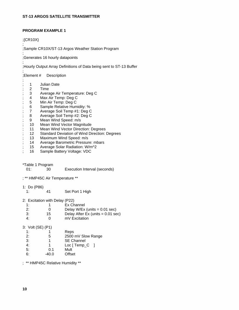
The first program example below demonstratesa basic weather station application oftransferring 16 low resolution data points to theST-13 buffer. The Datalogger then sends acommand to have the ST-13 begin itstransmission sequence.
The second program example is an alternativeprogramming method to send more than 16new data points over the satellite link. This isdescribed in program example B above.
ST-13 ARGOS SATELLITE TRANSMITTER
10
PROGRAM EXAMPLE 1
;{CR10X};;Sample CR10X/ST-13 Argos Weather Station Program;;Generates 16 hourly datapoints;;Hourly Output Array Definitions of Data being sent to ST-13 Buffer;;Element # Description;; 1 Julian Date; 2 Time; 3 Average Air Temperature: Deg C; 4 Max Air Temp: Deg C; 5 Min Air Temp: Deg C; 6 Sample Relative Humidity: %; 7 Average Soil Temp #1: Deg C; 8 Average Soil Temp #2: Deg C; 9 Mean Wind Speed: m/s; 10 Mean Wind Vector Magnitude; 11 Mean Wind Vector Direction: Degrees; 12 Standard Deviation of Wind Direction: Degrees; 13 Maximum Wind Speed: m/s; 14 Average Barometric Pressure: mbars; 15 Average Solar Radiation: W/m^2; 16 Sample Battery Voltage: VDC
*Table 1 Program01: 30 Execution Interval (seconds)
; ** HMP45C Air Temperature **
1: Do (P86)1: 41 Set Port 1 High
2: Excitation with Delay (P22)1: 1 Ex Channel2: 0 Delay W/Ex (units = 0.01 sec)3: 15 Delay After Ex (units = 0.01 sec)4: 0 mV Excitation
3: Volt (SE) (P1)1: 1 Reps2: 5 2500 mV Slow Range3: 1 SE Channel4: 1 Loc [ Temp_C ]5: 0.1 Mult6: -40.0 Offset
; ** HMP45C Relative Humidity **
ST-13 ARGOS SATELLITE TRANSMITTER
11
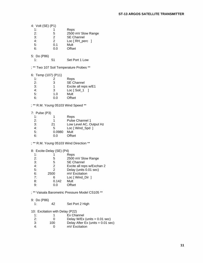
4: Volt (SE) (P1)1: 1 Reps2: 5 2500 mV Slow Range3: 2 SE Channel4: 2 Loc [ RH_perc ]5: 0.1 Mult6: 0.0 Offset
5: Do (P86)1: 51 Set Port 1 Low
; ** Two 107 Soil Temperature Probes **
6: Temp (107) (P11)1: 2 Reps2: 3 SE Channel3: 1 Excite all reps w/E14: 3 Loc [ Soil_1 ]5: 1.0 Mult6: 0.0 Offset
; ** R.M. Young 05103 Wind Speed **
7: Pulse (P3)1: 1 Reps2: 1 Pulse Channel 13: 21 Low Level AC, Output Hz4: 5 Loc [ Wind_Spd ]5: 0.0980 Mult6: 0.0 Offset
; ** R.M. Young 05103 Wind Direction **
8: Excite-Delay (SE) (P4)1: 1 Reps2: 5 2500 mV Slow Range3: 5 SE Channel4: 2 Excite all reps w/Exchan 25: 2 Delay (units 0.01 sec)6: 2500 mV Excitation7: 6 Loc [ Wind_Dir ]8: 0.142 Mult9: 0.0 Offset
; ** Vaisala Barometric Pressure Model CS105 **
9: Do (P86)1: 42 Set Port 2 High
10: Excitation with Delay (P22)1: 1 Ex Channel2: 0 Delay W/Ex (units = 0.01 sec)3: 100 Delay After Ex (units = 0.01 sec)4: 0 mV Excitation
ST-13 ARGOS SATELLITE TRANSMITTER
12
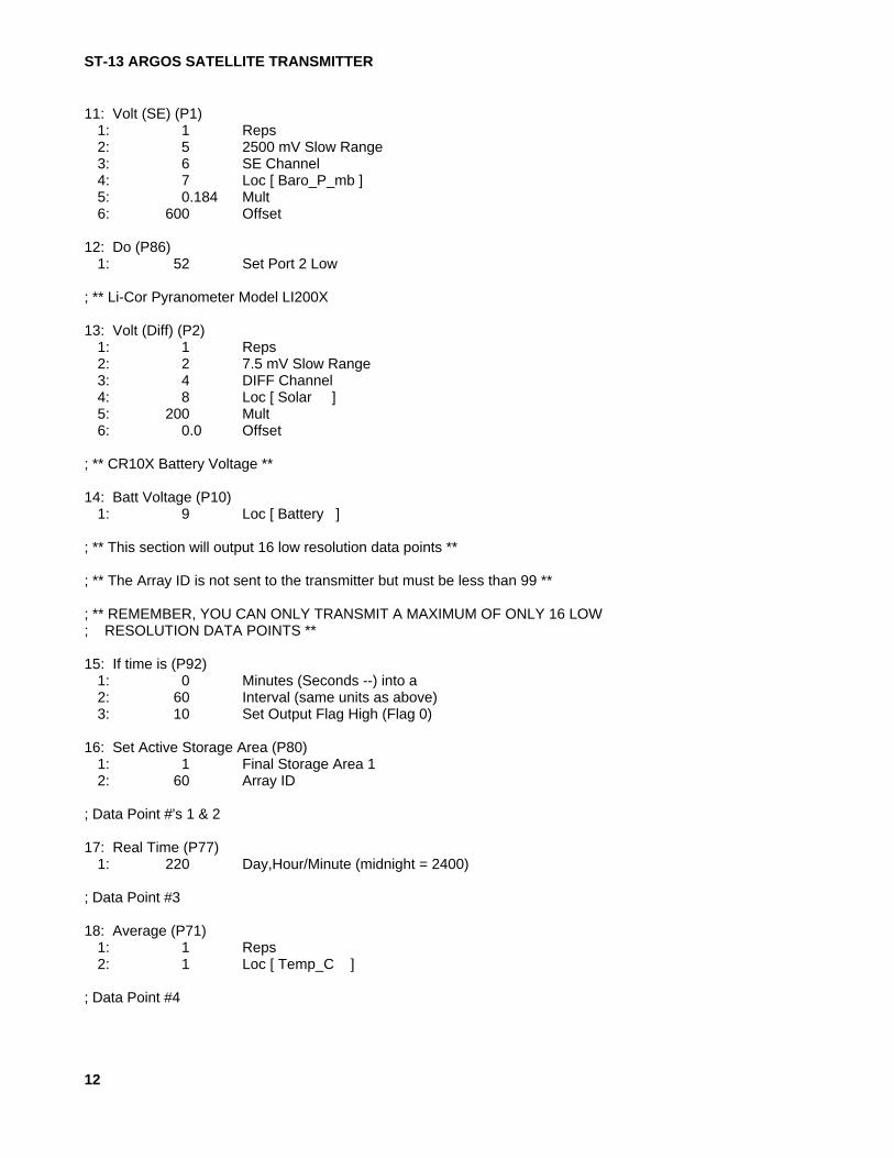
11: Volt (SE) (P1)1: 1 Reps2: 5 2500 mV Slow Range3: 6 SE Channel4: 7 Loc [ Baro_P_mb ]5: 0.184 Mult6: 600 Offset
12: Do (P86)1: 52 Set Port 2 Low
; ** Li-Cor Pyranometer Model LI200X
13: Volt (Diff) (P2)1: 1 Reps2: 2 7.5 mV Slow Range3: 4 DIFF Channel4: 8 Loc [ Solar ]5: 200 Mult6: 0.0 Offset
; ** CR10X Battery Voltage **
14: Batt Voltage (P10)1: 9 Loc [ Battery ]
; ** This section will output 16 low resolution data points **
; ** The Array ID is not sent to the transmitter but must be less than 99 **
; ** REMEMBER, YOU CAN ONLY TRANSMIT A MAXIMUM OF ONLY 16 LOW; RESOLUTION DATA POINTS **
15: If time is (P92)1: 0 Minutes (Seconds --) into a2: 60 Interval (same units as above)3: 10 Set Output Flag High (Flag 0)
16: Set Active Storage Area (P80)1: 1 Final Storage Area 12: 60 Array ID
; Data Point #'s 1 & 2
17: Real Time (P77)1: 220 Day,Hour/Minute (midnight = 2400)
; Data Point #3
18: Average (P71)1: 1 Reps2: 1 Loc [ Temp_C ]
; Data Point #4
ST-13 ARGOS SATELLITE TRANSMITTER
13
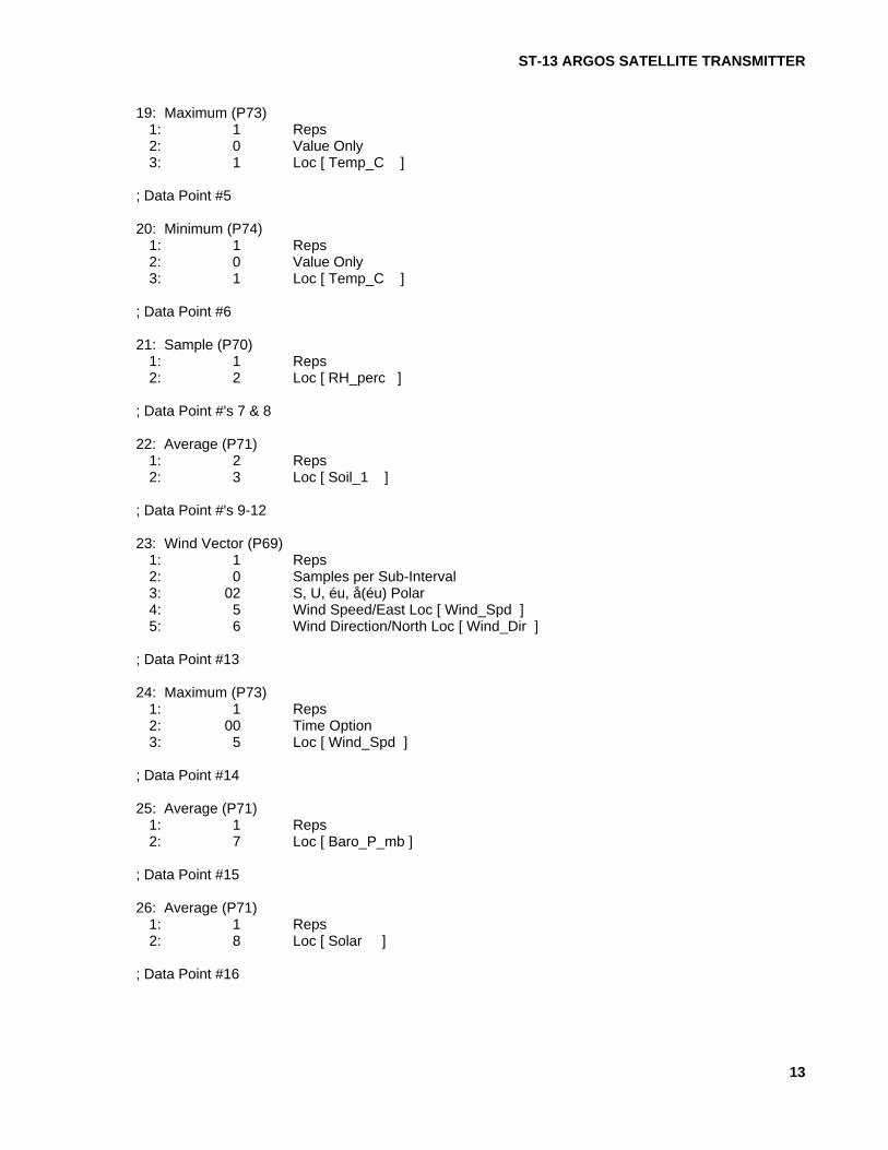
19: Maximum (P73)1: 1 Reps2: 0 Value Only3: 1 Loc [ Temp_C ]
; Data Point #5
20: Minimum (P74)1: 1 Reps2: 0 Value Only3: 1 Loc [ Temp_C ]
; Data Point #6
21: Sample (P70)1: 1 Reps2: 2 Loc [ RH_perc ]
; Data Point #'s 7 & 8
22: Average (P71)1: 2 Reps2: 3 Loc [ Soil_1 ]
; Data Point #'s 9-12
23: Wind Vector (P69)1: 1 Reps2: 0 Samples per Sub-Interval3: 02 S, U, éu, å(éu) Polar4: 5 Wind Speed/East Loc [ Wind_Spd ]5: 6 Wind Direction/North Loc [ Wind_Dir ]
; Data Point #13
24: Maximum (P73)1: 1 Reps2: 00 Time Option3: 5 Loc [ Wind_Spd ]
; Data Point #14
25: Average (P71)1: 1 Reps2: 7 Loc [ Baro_P_mb ]
; Data Point #15
26: Average (P71)1: 1 Reps2: 8 Loc [ Solar ]
; Data Point #16
ST-13 ARGOS SATELLITE TRANSMITTER
14
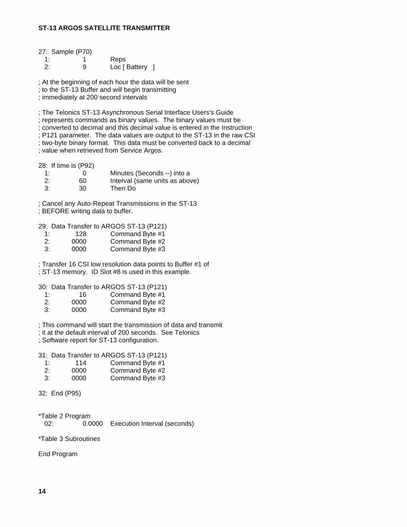
27: Sample (P70)1: 1 Reps2: 9 Loc [ Battery ]
; At the beginning of each hour the data will be sent; to the ST-13 Buffer and will begin transmitting; immediately at 200 second intervals
; The Telonics ST-13 Asynchronous Serial Interface Users's Guide; represents commands as binary values. The binary values must be; converted to decimal and this decimal value is entered in the Instruction; P121 parameter. The data values are output to the ST-13 in the raw CSI; two-byte binary format. This data must be converted back to a decimal; value when retrieved from Service Argos.
28: If time is (P92)1: 0 Minutes (Seconds --) into a2: 60 Interval (same units as above)3: 30 Then Do
; Cancel any Auto-Repeat Transmissions in the ST-13; BEFORE writing data to buffer.
29: Data Transfer to ARGOS ST-13 (P121)1: 128 Command Byte #12: 0000 Command Byte #23: 0000 Command Byte #3
; Transfer 16 CSI low resolution data points to Buffer #1 of; ST-13 memory. ID Slot #8 is used in this example.
30: Data Transfer to ARGOS ST-13 (P121)1: 16 Command Byte #12: 0000 Command Byte #23: 0000 Command Byte #3
; This command will start the transmission of data and transmit; it at the default interval of 200 seconds. See Telonics; Software report for ST-13 configuration.
31: Data Transfer to ARGOS ST-13 (P121)1: 114 Command Byte #12: 0000 Command Byte #23: 0000 Command Byte #3
32: End (P95)
*Table 2 Program02: 0.0000 Execution Interval (seconds)
*Table 3 Subroutines
End Program

ST-13 ARGOS SATELLITE TRANSMITTER
15
1 [ Temp_C ] RW-- 3 1 ----- ------ ---2 [ RH_perc ] RW-- 1 1 ----- ------ ---3 [ Soil_1 ] RW-- 1 1 Start ------ ---4 [ Soil_2 ] RW-- 1 1 ----- ------ End5 [ Wind_Spd ] RW-- 2 1 ----- ------ ---6 [ Wind_Dir ] RW-- 1 1 ----- ------ ---7 [ Baro_P_mb ] RW-- 1 1 ----- ------ ---8 [ Solar ] RW-- 1 1 ----- ------ ---9 [ Battery ] RW-- 1 1 ----- ------ ---
PROGRAM EXAMPLE 2
1;{CR10X};;Alternate programming method to send more than;16 datapoints over the satellite link.;;----------------;PROGRAM EXAMPLE:;----------------;;20 minute floating buffer for ST-13/ARGOS system.;;CR10 controls 90 second transmission of alternating;20 minute data. Alternately this can be used to only;transfer data to the ST-13 and not force a transmission.;;-------;THEORY:;-------;PART 1 MOVING 20 MINUTE DATA;;Measurements occur in Locations 1-14 (User Defined).;Every 20 minutes processed data (maxima, minima,;averages, etc.) + Timestamp (Julian Date, Time) are;placed back into 16 sequential input locations 49-64.;;PRIOR to putting data into these input locations,;data is shifted in blocks of 16 datapoints:;;First: Data in input locations 33 to 48 are moved;sequentially to input locations 17 to 32.;;Second: Data in input locations 49 to 64 are moved;sequentially to input locations 33 to 48.;;Third: Newly Processed 20 minute Data is written;back into input locations 49 to 64.;

ST-13 ARGOS SATELLITE TRANSMITTER
16
;;PART 2 TRANSFERRING AND TRANSMITTING ALTERNATING;20 MINUTE DATA EVERY 90 SECONDS;;P26 is used as the 90 second timer and should be placed;as the very first instruction in the 30 second Table,;(TABLE 1).;;When the timer = 90 seconds a counter is initiated to 1;and will increment by 1 every 90 seconds to a maximum;of 3. (3 representing the (3) 20 minute arrays).;When the counter = 3 it is zeroed.;;The TIMER is zeroed each timer it equals 90 seconds.;;;When the counter=1 processed data from input locations;17 to 32 are sampled and sent to final storage area 2.;P99 is executed to send data to the ST-13 buffer #1 and;then it is immediately transmitted.;;90 seconds later the counter = 2 and processed data;in input locations 33 to 48 are sampled to final;storage area 2. P99 is executed to send data to the;ST-13 buffer #1 and then it is immediately transmitted.;;90 seconds later the counter = 3 and processed data;in input locations 49 to 64 are sampled to final;storage area 2. P99 is executed to send data to the;ST5 buffer #1 and then it is immediately transmitted.;;When the COUNTER = 3 it is zeroed, and the counter will;increment to 1 90 seconds later.*Table 1 Program
01: 30 Execution Interval (seconds);;** P26 used for 90 second control timer **
1: Timer (P26)1: 63 Loc [ Timer ]
;;** Move a block of 16 Datapoints from locations;33 to 48 to locations 17 through 32 every 20 minutes;BEFORE shifting data from locations 49 through 64 to;33 through 48.
2: If time is (P92)1: 0 Minutes (Seconds --) into a2: 20 Interval (same units as above)3: 30 Then Do
;;>>> 20 min DATA BLOCK SHIFT #1 <<<

ST-13 ARGOS SATELLITE TRANSMITTER
17
3: Block Move (P54)1: 16 No. of Values2: 31 First Source Loc [ BlockB_1 ]3: 1 Source Step4: 15 First Destination Loc [ BlockA_1 ]5: 1 Destination Step
;;>>> 20 min DATA BLOCK SHIFT #2 <<<;** Move a block of 16 datapoints from locations;from 49 through 64, to 33 through 48.
4: Block Move (P54)1: 16 No. of Values2: 47 First Source Loc [ BlockC_1 ]3: 1 Source Step4: 31 First Destination Loc [ BlockB_1 ]5: 1 Destination Step
;;** P95 End Block Move **
5: End (P95);;** Output 20 minute processed data **
6: If time is (P92)1: 0 Minutes (Seconds --) into a2: 20 Interval (same units as above)3: 10 Set Output Flag High
;;** Send processed data to input locations 49 to 64 **
7: Set Active Storage Area (P80)1: 3 Input Storage Area2: 47 Array ID or Loc [ BlockC_1 ]
;;** Timestamp (Datapoints 1 & 2) **
8: Real Time (P77)1: 220 Day,Hour/Minute (midnight = 2400)
;;** Processed Data (Datapoints 3 to 16)
9: Average (P71)1: 14 Reps2: 1 Loc [ Meas__1 ]
;;** If the timer = 90 seconds then DO **
10: If (X<=>F) (P89)1: 63 X Loc [ Timer ]2: 3 >=3: 90 F4: 30 Then Do
;;** Start Counter **

ST-13 ARGOS SATELLITE TRANSMITTER
18
11: Z=Z+1 (P32)1: 64 Z Loc [ Counter ]
;;** If counter = 1 then DO **
12: If (X<=>F) (P89)1: 64 X Loc [ Counter ]2: 1 =3: 1 F4: 30 Then Do
;;** Output Data to Final Storage Area 2 **
13: Set Active Storage Area (P80)1: 2 Final Storage Area 22: 1 Array ID or Loc [ Meas__1 ]
;;** Set Output Flag HI (10) **
14: Do (P86)1: 10 Set Output Flag High
;;** Send first 16 datapoints to Final Storage Area 2 **
15: Sample (P70)1: 16 Reps2: 15 Loc [ BlockA_1 ]
;;** Zero 90 second Timer for next Interval *
16: Timer (P26)1: 63 Loc [ Timer ]
;;** Send 16 datapoints to ST-13 Buffer #1 and Transmit **;;>>> OR USE 16 IN THE FIRST BYTE INSTEAD OF 48 <<<;>>> 23 WILL ONLY DUMP DATA AND NOT TRANSMIT <<<
17: Data Transfer to ARGOS ST-13 (P121)1: 48 Command Byte #12: 0000 Command Byte #23: 0000 Command Byte #3
;;** P95 End if Counter = 1 **
18: End (P95);;** If counter = 2 then DO **
19: If (X<=>F) (P89)1: 64 X Loc [ Counter ]2: 1 =3: 2 F4: 30 Then Do
;

ST-13 ARGOS SATELLITE TRANSMITTER
19
;** Output Data to Final Storage Area 2 **
20: Set Active Storage Area (P80)1: 2 Final Storage Area 22: 2 Array ID or Loc [ Meas__2 ]
21: Do (P86)1: 10 Set Output Flag High
;;** Output Next 16 Datapoints **
22: Sample (P70)1: 16 Reps2: 31 Loc [ BlockB_1 ]
;;** Zero 90 second Timer for next interval **
23: Timer (P26)1: 63 Loc [ Timer ]
;;** Send 16 datapoints to ST5 Buffer #1 and Transmit **;;>>> OR USE 16 INSTEAD OF 48 IN THE FIRST BYTE <<<;>>> 16 WILL ONLY DUMP DATA AND NOT TRANSMIT <<<
24: Data Transfer to ARGOS ST-13 (P121)1: 48 Command Byte #12: 0000 Command Byte #23: 0000 Command Byte #3
;** P95 End if counter = 2 **
25: End (P95);;** If counter = 3 then DO **
26: If (X<=>F) (P89)1: 64 X Loc [ Counter ]2: 1 =3: 3 F4: 30 Then Do
;;** Output Data to Final Storage Area 2 **
27: Set Active Storage Area (P80)1: 2 Final Storage Area 22: 3 Array ID or Loc [ Meas__3 ]
28: Do (P86)1: 10 Set Output Flag High
;;** Output 16 Datapoints **
29: Sample (P70)1: 16 Reps2: 47 Loc [ BlockC_1 ]

ST-13 ARGOS SATELLITE TRANSMITTER
20
;;** Zero Counter **
30: Z=F (P30)1: 0 F2: 0 Exponent of 103: 64 Z Loc [ Counter ]
;;** Zero 90 second timer for next interval **
31: Timer (P26)1: 63 Loc [ Timer ]
;;** Send 16 Datapoints to ST5 Buffer #1 and Transmit **;;>>> OR USE 16 INSTEAD OF 48 IN THE FIRST BYTE <<<;>>> 16 WILL ONLY DUMP DATA AND NOT TRANSMIT <<<
32: Data Transfer to ARGOS ST-13 (P121)1: 48 Command Byte #12: 0000 Command Byte #23: 0000 Command Byte #3
;;** P95 End if Counter = 3 **
33: End (P95);;** End if Timer = 90 **
34: End (P95)
*Table 2 Program 02: 0.0000 Execution Interval (seconds)
*Table 3 Subroutines
End Program
1 [ Meas__1 ] R--- 1 0 ----- ------ ---2 [ Meas__2 ] R--- 1 0 ----- ------ ---3 [ Meas__3 ] R--- 1 0 ----- ------ ---4 [ Meas__4 ] R--- 1 0 ----- ------ ---5 [ Meas__5 ] R--- 1 0 ----- ------ ---6 [ Meas__6 ] R--- 1 0 ----- ------ ---7 [ Meas__7 ] R--- 1 0 ----- ------ ---8 [ Meas__8 ] R--- 1 0 ----- ------ ---9 [ Meas__9 ] R--- 1 0 ----- ------ --- 10 [ Meas__10 ] R--- 1 0 ----- ------ ---11 [ Meas__11 ] R--- 1 0 ----- ------ ---12 [ Meas__12 ] R--- 1 0 ----- ------ ---13 [ Meas__13 ] R--- 1 0 ----- ------ ---14 [ Meas__14 ] R--- 1 0 ----- ------ ---15 [ BlockA_1 ] RW-- 1 1 Start ------ ---16 [ BlockA_2 ] RW-- 1 1 ----- Member ---17 [ BlockA_3 ] RW-- 1 1 ----- Member ---

ST-13 ARGOS SATELLITE TRANSMITTER
21
18 [ BlockA_4 ] RW-- 1 1 ----- Member ---19 [ BlockA_5 ] RW-- 1 1 ----- Member ---20 [ BlockA_6 ] RW-- 1 1 ----- Member ---21 [ BlockA_7 ] RW-- 1 1 ----- Member ---22 [ BlockA_8 ] RW-- 1 1 ----- Member ---23 [ BlockA_9 ] RW-- 1 1 ----- Member ---24 [ BlockA_10 ] RW-- 1 1 ----- Member ---25 [ BlockA_11 ] RW-- 1 1 ----- Member ---26 [ BlockA_12 ] RW-- 1 1 ----- Member ---27 [ BlockA_13 ] RW-- 1 1 ----- Member ---28 [ BlockA_14 ] RW-- 1 1 ----- Member ---29 [ BlockA_15 ] RW-- 1 1 ----- Member ---30 [ BlockA_16 ] RW-- 1 1 ----- ------ End31 [ BlockB_1 ] RW-- 2 1 Start ------ ---32 [ BlockB_2 ] RW-- 2 1 ----- Member ---33 [ BlockB_3 ] RW-- 2 1 ----- Member ---34 [ BlockB_4 ] RW-- 2 1 ----- Member ---35 [ BlockB_5 ] RW-- 2 1 ----- Member --- 36 [ BlockB_6 ] RW-- 2 1 ----- Member ---37 [ BlockB_7 ] RW-- 2 1 ----- Member ---38 [ BlockB_8 ] RW-- 2 1 ----- Member ---39 [ BlockB_9 ] RW-- 2 1 ----- Member ---40 [ BlockB_10 ] RW-- 2 1 ----- Member ---41 [ BlockB_11 ] RW-- 2 1 ----- Member ---42 [ BlockB_12 ] RW-- 2 1 ----- Member ---43 [ BlockB_13 ] RW-- 2 1 ----- Member ---44 [ BlockB_14 ] RW-- 2 1 ----- Member ---45 [ BlockB_15 ] RW-- 2 1 ----- Member ---46 [ BlockB_16 ] RW-- 2 1 ----- ------ End47 [ BlockC_1 ] RW-- 2 1 ----- ------ ---48 [ BlockC_2 ] R--- 2 0 ----- ------ ---49 [ BlockC_3 ] R--- 2 0 ----- ------ ---50 [ BlockC_4 ] R--- 2 0 ----- ------ ---51 [ BlockC_5 ] R--- 2 0 ----- ------ ---52 [ BlockC_6 ] R--- 2 0 ----- ------ ---53 [ BlockC_7 ] R--- 2 0 ----- ------ ---54 [ BlockC_8 ] R--- 2 0 ----- ------ ---55 [ BlockC_9 ] R--- 2 0 ----- ------ ---56 [ BlockC_10 ] R--- 2 0 ----- ------ ---57 [ BlockC_11 ] R--- 2 0 ----- ------ ---58 [ BlockC_12 ] R--- 2 0 ----- ------ ---59 [ BlockC_13 ] R--- 2 0 ----- ------ ---60 [ BlockC_14 ] R--- 2 0 ----- ------ ---61 [ BlockC_15 ] R--- 2 0 ----- ------ --- 62 [ BlockC_16 ] R--- 2 0 ----- ------ ---63 [ Timer ] RW-- 1 4 ----- ------ ---64 [ Counter ] RW-- 3 2 ----- ------ ---

A-1
APPENDIX A. TELONICS ST-13ASYNCHRONOUS SERIAL INTERFACE
A.1 SCOPE
This document is intended to provide the userwith the information needed to understand theserial interface capability of the ST-13. Itprovides an overview of the ST-13 and definesthe hardware configuration and logical interfacein sufficient detail to allow direct command andcontrol operation of the ST-13 via the user's hostcomputer system. The Hardware Configurationand the Electrical Interface sections of thismanual define the voltage levels, pinouts and pin-loading specifications for the hardware linkbetween the ST-13 and the host system. TheSerial Communications and Commandingsections describe the logical software protocolused for passing commands from the hostcomputer to the ST-13, and the ST-13'sresponse back to the host.
A.2 OVERVIEW
The ST-13 is a certified ARGOS PTT (PlatformTransmitter Terminal). It may be interfaced to auser's data collection system, providing uplinkcapability for the user's experiment. The ST-13contains a full-duplex asynchronous serialcommunications interface through which the hostcomputer of the user's data collection systemmay transfer any data to the ST-13 that are to betransmitted to the satellite. ST-13 RF messagesare transmitted via the ARGOS DCLS on boardNOAA polar orbiting satellites. Because the ST-13 directly controls the RF uplink (i.e.,modulation, timing, and failsafe shut-down) andis already certified, the user's composite systemdoes not have to undergo the rigorous ARGOScertification process.
The ARGOS system can support severalconcurrent experiments. Each experiment istotally independent and may transmit data to thesatellite at almost any time. ARGOS confineseach experiment to a specified transmission rep-rate. Since many independent experiments maybe transmitting data to the same satellite atnearly, or even exactly the same time, ARGOSsorts the received data so that they can be routedback to the proper owner. To accomplish this,ARGOS assigns a unique ID code to eachexperiment. In addition to the data transferredfrom the host computer system to the ST-13,
these ID codes are also part of everytransmission sent by the ST-13.
ID codes must be acquired from ARGOS by theexperiment owner, and presented to Telonicswhen an ST-13 is ordered. These ID codes aregenerally programmed into the ST-13 before itleaves the factory. Each ST-13 can support upto 8 ID codes. This allows for one PTT toperform multiple experiments, or for a singleexperiment to transmit more data than can betransmitted via a single ID code. Note that dataare transmitted in multiples of 32-bit words (4-bytes per word). The shortest data message is 1word (4 bytes) and the longest is 8 words (32bytes). Each ID code assigned by ARGOS hasassociated with it a message length in number ofwords, and each transmission using a given IDcode must transmit the correct number of words.Therefore, the message length for each ID codemust also be programmed into the ST-13, usuallyat the factory.
Therefore, when the host wishes to send data tothe ST-13, it sends a command byte whichspecifies the function to be performed (such asStore Data or Transmit ), and an ID code toassociate with the data being passed ortransmitted. Because message length is alreadyassigned to each ID code, specifying an ID codeindirectly specifies to the ST-13 the number ofdata words, hence, the number of bytes to betransferred or transmitted. Since up to 8 IDcodes may be stored in the ST-13, specifying anID code is accomplished by passing a numberbetween 0 and 7 which acts as an index into theST-13's internal table of stored ID codes. Thisindex number is actually part of the passedcommand byte.
All message data passed to the ST-13 is storedin one of two internal buffers, known asbuffer 1 and buffer 2. The host computerspecifies which buffer is to be used by way of thespecified command. For instance, the StoreData 1 command stores data into buffer 1, andthe Store Data 2 command stores data intobuffer 2. This allows the host greater flexibility inhandling the data to be transmitted.

APPENDIX A. TELONICS ST-13 ASYNCHRONOUS SERIAL INTERFACE
A-2
As can be seen, the data that the ST-13transmits comes from the host computer. Whenthese transmissions occur, however, is anothermatter. Initiation of transmissions may becontrolled by either the host computer or the ST-13. The ST-13 supports commands that initiatetransmissions under the auspices of the hostcomputer. This puts the entire burden of whentransmissions occur upon the host. The ST-13also supports a mode known as Auto-Repeat,which allows the host to tell the ST-13 when tobegin a series of up to 255 transmissions withoutany further intervention by the host. This modecan greatly lighten the burden on the host. Notethat it is typical for the same message to betransmitted several times in order to ensuresuccessful reception of the data by a satellite.The Auto-Repeat mode is extremely useful foraccomplishing this function.
Examination of Figures A-3, A-4, and A-5, showsthat transmissions consist of long serial streamsof data. Although the host computer may be incharge of when transmissions occur, there is noneed for the host to worry about any of the detailsof the transmission itself. The ST-13 handles allof the serial data stream generation and thecomplex timing of the entire transmission.
The ST-13 supports two additional modes whichare unique enough to bear introduction. The ST-13 constantly monitors the quality of thecommunication link with the host computer, andcan identify several types of errors, should theyoccur. It maintains a history of the most recenterrors and a count of the total number of errorsthat have occurred. If the ST-13 were to keepthis information to itself, it would be useless.Therefore, a mode, known as Transmit ErrorCounts, is supported to allow the ST-13 to injectthis information into the host's data message.When this mode is turned on, the ST-13'sinternal error information is included in the datamessage, which allows the experiment owner tomonitor conditions internal to the system. Thismode can identify communication problemsbetween the host and the ST-13 during the user'sdevelopment phase, as well as show degradingconditions (such as might occur due to waterleakage) which can greatly assist inunderstanding system failures in the field. Thismode may be turned on and off by the hostcomputer at any time. (Note that this mode maybe permanently disabled at the time an ST-13 isordered.)
The ST-13 also supports a mode known asFailSafe. With this mode enabled, should acatastrophic communications link failure occurbetween the host computer and the ST-13, theST-13 can detect when a preset time limit hasexpired without successfully receiving acommand from the host computer. This timelimit is specifiable when the ST-13 is ordered,and may be set from one minute to 255 days. Ifthis condition is detected, the ST-13 will begintransmitting a FailSafe message, which willinclude the error count and history informationdescribed above. These FailSafe transmissions,while not conveying any useful experiment data,may be useful in discerning the reason for thefailure, and may be used to position fix thetroubled PTT. (Note that this mode may bepermanently disabled at the time an ST-13 isordered.)
A.3 SERIAL COMMUNICATION -HARDWARE CONFIGURATION
The ST-13 may be ordered with either a TTL (5volt) or RS-232 interface. Connection to the ST-13 for the purpose of control via theasynchronous serial port is accomplished using amale DB-25 connector (refer to Appendix A,"ST-13 I/O Connector Pinouts"). The pinconnections at the ST-13 are as follows:
Pin 1 -- Async Wake-up Signal:
TTL: This line is pulledhigh ( +5V) at the ST-13through a 100K Ohmresistor. Pulling this linelow will cause awake-up interrupt in theST-13.
RS-232: This line ispulled to groundthrough a 30K Ohmresistor. The idle stateof this line is low (0 to -15V). Pulling this linehigh (+5 to +15V) willcause a wake-upinterrupt.
Pin 2 -- TXD: Used to transmitdata from the ST-13 tothe host.

APPENDIX A. TELONICS ST-13 ASYNCHRONOUS SERIAL INTERFACE
A-3
TTL: This line isnormally at +5V andpulled low for Start bitsand Zero bits. One bitsare represented by +5V.This line will remain at+5V even when the ST-13 is betweencommands from thehost.
RS-232: This line isdriven by a RS-232 linedriver. When the ST-13is awake andcommunicating with thehost, the idle state ofthis line is low (-5 to -15V). Start bits andZero bits aretransmitted with this linein the high state (+5 to+15V). One bits aretransmitted with this linein the low state (-5 to -15V). Note that whenthe ST-13 is NOTcommunicating with thehost (i.e., betweencommands), the RS-232 driver chip ispowered down to savebattery power. Thiscauses the TXD pin tobe pulled toward 0V.The host system MUSTbe aware of this anddisable its receiverduring this time.
Pin 13 -- Common ground fortransmit, receive andwake-up signals.
Pin 14 -- RXD: Used by the ST-13 to receive data fromthe host.
TTL: This line isnormally pulled high(nominal +5V) at theST-13 through a 1 megOhm resistor. This lineis to be pulled low bythe host for Start bits
and Zero bits, and lefthigh for One bits.
RS-232: This line isconnected to a RS-232line receiver which hasan internal 5K Ohmresistor to ground. Thehost should hold thisline low (-5 to -15V) forthe idle state and forOne bits. The lineshould be driven high(+5 to +15V) for Startbits and Zero bits.
Pin 22 -- CR: +5 volt source usedin some applicationsrequiring pull-ups.
WARNING: When using the TTL interface,exceeding +5.5V on any pin may damagethe ST-13. Inputs are static sensitive.
NOTE: For the TTL interface option, thepolarity of the TXD and RXD signals exactlymatches the corresponding pins on mostUARTs. This typically allows for directconnection between the ST-13 and thehost's UART.
A.4 ELECTRICAL INTERFACE AND I/OPIN LOADING
Figure A-1 illustrates the termination of the serialI/O pins internal to the ST-13 for the TTLinterface option. Each pin is RF filtered. A series10K resistor current limits the pins and protectsfrom nominal over-voltage conditions and static.Each pin has a pull-up resistor to +5v.
In order to overcome the 220 pF capacitiveloading on the input pins to the ST-13, each inputshould be driven by a device in the host with anactive pull-up. This works well when the host andthe ST-13 will always be powered up together.However, if the host is always going to bepowered up and the ST-13 is going to bepowered down for extended periods, the activedrivers in the host will cause supply current to bewasted by attempting to hold the ST-13's inputpins high.
In instances requiring the ST-13 to be powereddown for long periods of time, it is advisable to

APPENDIX A. TELONICS ST-13 ASYNCHRONOUS SERIAL INTERFACE
A-4
use open-collector or open-drain transistors todrive the ST-13 input pins. When doing this, it isnecessary to add additional 100K pull-upresistors between pin 22 (CR) and pins 1 and 14(Wake-Up and RXD) on the ST-13's I/Oconnector. This is because the pull-up resistorsinternal to the ST-13 (100K and 1M respectively)are insufficient to overcome the capacitiveloading and leakage current of the drivingtransistor, especially at higher baud rates.
Pin 2 of the ST-13 I/O connector (TXD) is drivenby an active device internal to the ST-13. Theinternal series 10K resistor protects this devicefrom external shorts. Make sure that the pin
which receives this signal in the host has an inputimpedance much larger than 10K ohms. If theST-13 is powered-down, it will tend to drag thispin low.
Figure A-2 illustrates the termination of the serialI/O pins internal to the ST-13 for the RS-232interface option. Each pin is RF filtered. TheWake-Up pin has 30K of resistance to ground.The TXD and RXD pins come directly from a RS-232 driver/receiver chip. Note that this chip ispowered on when a Wake-Up signal is received,and powered off after reception of the completecommand from the host.
+5V
+5V
10K
0.047uF
CRPin 22
Rpu10K
220pF
I/OPins 1, 2, 14
FerriteBead
To Logic Input, orActive Driver Output
FIGURE A-1. Serial I/O, TTL Termination
10K
220pF
Wake UpPin 1
FerriteBead
To Logic Input
20K
220pF
220pF
Tx
Rx
5K
From Active Driver
To Logic Input
RS-232 Driver/Receiver Switched Power
TXDPin 2
RXDPin 14
FIGURE A-2. Serial I/O, RS-232 Termination
APPENDIX A. TELONICS ST-13 ASYNCHRONOUS SERIAL INTERFACE
A-5
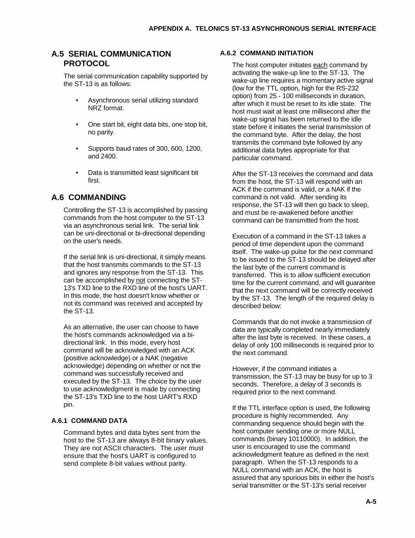
A.5 SERIAL COMMUNICATIONPROTOCOL
The serial communication capability supported bythe ST-13 is as follows:
• Asynchronous serial utilizing standardNRZ format.
• One start bit, eight data bits, one stop bit,no parity.
• Supports baud rates of 300, 600, 1200,and 2400.
• Data is transmitted least significant bitfirst.
A.6 COMMANDING
Controlling the ST-13 is accomplished by passingcommands from the host computer to the ST-13via an asynchronous serial link. The serial linkcan be uni-directional or bi-directional dependingon the user's needs.
If the serial link is uni-directional, it simply meansthat the host transmits commands to the ST-13and ignores any response from the ST-13. Thiscan be accomplished by not connecting the ST-13's TXD line to the RXD line of the host's UART.In this mode, the host doesn't know whether ornot its command was received and accepted bythe ST-13.
As an alternative, the user can choose to havethe host's commands acknowledged via a bi-directional link. In this mode, every hostcommand will be acknowledged with an ACK(positive acknowledge) or a NAK (negativeacknowledge) depending on whether or not thecommand was successfully received andexecuted by the ST-13. The choice by the userto use acknowledgment is made by connectingthe ST-13's TXD line to the host UART's RXDpin.
A.6.1 COMMAND DATA
Command bytes and data bytes sent from thehost to the ST-13 are always 8-bit binary values.They are not ASCII characters. The user mustensure that the host's UART is configured tosend complete 8-bit values without parity.
A.6.2 COMMAND INITIATION
The host computer initiates each command byactivating the wake-up line to the ST-13. Thewake-up line requires a momentary active signal(low for the TTL option, high for the RS-232option) from 25 - 100 milliseconds in duration,after which it must be reset to its idle state. Thehost must wait at least one millisecond after thewake-up signal has been returned to the idlestate before it initiates the serial transmission ofthe command byte. After the delay, the hosttransmits the command byte followed by anyadditional data bytes appropriate for thatparticular command.
After the ST-13 receives the command and datafrom the host, the ST-13 will respond with anACK if the command is valid, or a NAK if thecommand is not valid. After sending itsresponse, the ST-13 will then go back to sleep,and must be re-awakened before anothercommand can be transmitted from the host.
Execution of a command in the ST-13 takes aperiod of time dependent upon the commanditself. The wake-up pulse for the next commandto be issued to the ST-13 should be delayed afterthe last byte of the current command istransferred. This is to allow sufficient executiontime for the current command, and will guaranteethat the next command will be correctly receivedby the ST-13. The length of the required delay isdescribed below:
Commands that do not invoke a transmission ofdata are typically completed nearly immediatelyafter the last byte is received. In these cases, adelay of only 100 milliseconds is required prior tothe next command.
However, if the command initiates atransmission, the ST-13 may be busy for up to 3seconds. Therefore, a delay of 3 seconds isrequired prior to the next command.
If the TTL interface option is used, the followingprocedure is highly recommended. Anycommanding sequence should begin with thehost computer sending one or more NULLcommands (binary 10110000). In addition, theuser is encouraged to use the commandacknowledgment feature as defined in the nextparagraph. When the ST-13 responds to aNULL command with an ACK, the host isassured that any spurious bits in either the host'sserial transmitter or the ST-13's serial receiver
APPENDIX A. TELONICS ST-13 ASYNCHRONOUS SERIAL INTERFACE
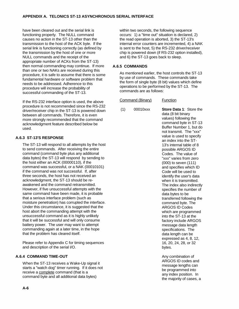
A-6
have been cleared out and the serial link isfunctioning properly. The NULL commandcauses no action in the ST-13 other than thetransmission to the host of the ACK byte. If theserial link is functioning correctly (as defined bythe transmission by the host of one or moreNULL commands and the receipt of theappropriate number of ACKs from the ST-13)then normal commanding may continue. If morethan one or two NAKs are received during thisprocedure, it is safe to assume that there is somefundamental hardware or software problem thatneeds to be addressed. Adherence to thisprocedure will increase the probability ofsuccessful commanding of the ST-13.
If the RS-232 interface option is used, the aboveprocedure is not recommended since the RS-232driver/receiver chip in the ST-13 is powered downbetween all commands. Therefore, it is evenmore strongly recommended that the commandacknowledgment feature described below beused.
A.6.3 ST-13'S RESPONSE
The ST-13 will respond to all attempts by the hostto send commands. After receiving the entirecommand (command byte plus any additionaldata bytes) the ST-13 will respond by sending tothe host either an ACK (00000110), if thecommand was successful, or a NAK (00010101)if the command was not successful. If, afterthree seconds, the host has not received anacknowledgment, the ST-13 should be re-awakened and the command retransmitted.However, if five unsuccessful attempts with thesame command have been made, it is probablethat a serious interface problem (such asmoisture penetration) has corrupted the interface.Under this circumstance, it is suggested that thehost abort the commanding attempt with theunsuccessful command as it is highly unlikelythat it will be successful and will only consumebattery power. The user may want to attemptcommanding again at a later time, in the hopethat the problem has cleared itself.
Please refer to Appendix C for timing sequencesand description of the serial I/O.
A.6.4 COMMAND TIME-OUT
When the ST-13 receives a Wake-Up signal itstarts a "watch dog" timer running. If it does notreceive a complete command (that is acommand byte and all additional data bytes)
within two seconds, the following sequenceoccurs: 1) a "time out" situation is declared, 2)the read operation is aborted, 3) the ST-13'sinternal error counters are incremented, 4) a NAKis sent to the host, 5) the RS-232 driver/receiverchip is powered down (if RS-232 option installed),and 6) the ST-13 goes back to sleep.
A.6.5 COMMANDS
As mentioned earlier, the host controls the ST-13by use of commands. These commands takethe form of single byte (8 bit) values which defineoperations to be performed by the ST-13. Thecommands are as follows:
Command (Binary) Function
(1) 00010xxx Store Data 1 : Store thedata (8 bit binaryvalues) following thecommand byte in ST-13Buffer Number 1, but donot transmit. The "xxx"value is used to specifyan index into the ST-13's internal table of 8possible ARGOS IDCodes. The value of"xxx" varies from zero(000) to seven (111)and specifies which IDCode will be used toidentify the user's datawhen it is transmitted.The index also indirectlyspecifies the number ofdata bytes to betransferred following thecommand byte. TheARGOS ID Codeswhich are programmedinto the ST-13 at thefactory include ARGOSmessage data lengthspecifications. Thedata length can beexpressed as 4, 8, 12,16, 20, 24, 28, or 32bytes.
Any combination ofARGOS ID codes andmessage lengths canbe programmed intoany index position. Inthe majority of cases, a

APPENDIX A. TELONICS ST-13 ASYNCHRONOUS SERIAL INTERFACE
A-7
single ID code andassociated messagelength are required. Inthis case, index 0 isused.
If an insufficient numberof data bytes is receivedfrom the host, thesystem error counter isincremented, theoperation is aborted,and Buffer Number 1 ismarked as containingno data. If any Auto-Repeat operation is inprogress at this time, itwill be canceled in orderto avoid transmittinginvalid data.
If the host transfersbytes in excess of thatspecified by theARGOS ID Code, thesurplus bytes areignored, but the initialbytes are stored inBuffer Number 1 (noerror code isgenerated).
The following tabledefines the relationshipbetween the commandand the specifiedARGOS ID Code index.The actual ARGOS IDcodes are assigned tothe user by ARGOS,provided to Telonics bythe user, andprogrammed into theST-13 prior to shipmentfrom the factory. Notethat each ARGOS IDCode is associated witha message length codewhich specifies thenumber of 4-byte datagroups to betransmitted when aparticular ARGOS IDCode is used. Ifdesired, any givenARGOS ID Code can
be replicated in the ST-13's internal table. Thiswould permit the user totransmit any 4 byte dataincrement from 4 to 32bytes using the sameARGOS ID Code, ifappropriate.
Command Byte Binary Hex Decimal ID Index
00010000 $10 16 100010001 $11 17 200010010 $12 18 300010011 $13 19 400010100 $14 20 500010101 $15 21 600010110 $16 22 700010111 $17 23 8
(2) 00100xxx Store Data 2 : Store thedata bytes following thecommand byte in ST-13Buffer Number 2. Thiscommand is exactly likethe previous commandexcept the data aredirected to BufferNumber 2.
(3) 00110xxx Store and Transmit 1 :Store the following datain Buffer Number 1 andtransmit it immediately.This command isidentical to the firstcommand except thatthe data is immediatelytransmitted. The timebetween initiation of thecommand andcompletion of thetransmission can be aslong as 8 seconds. Noother commandsconcerning BufferNumber 1 should beinitiated in this timeframe to assure thattransmission of anintact buffer occurs.
(4) 01000xxx Store and Transmit 2 :Same as above, exceptthat data will be stored

APPENDIX A. TELONICS ST-13 ASYNCHRONOUS SERIAL INTERFACE
A-8
in Buffer Number 2 andthen immediatelytransmitted.
(5) 01010xxx Transmit 1 : Transmitthe data previouslystored in Buffer Number1. No data follows thiscommand byte. Thethree bit value "xxx"specifies one of apossible eight (0-7)different ARGOSidentification codes. Ifthe data messagelength associated withthe selectedidentification code isinconsistent with thelength of the data storedin Buffer Number 1, theoperation is aborted andthe system errorcounter is incremented.The time betweeninitiation of thecommand andcompletion of thetransmission can be aslong as 8 seconds. Noother commandsconcerning BufferNumber 1 should beinitiated in this timeframe to assure thattransmission of anintact buffer occurs.
(6) 01100xxx Transmit 2 : Transmitthe data previouslystored in Buffer Number2. No data follows thiscommand byte. Thethree bit value "xxx"specifies one of apossible eight (0-7)different ARGOSidentification codes. Ifthe data messagelength associated withthe selectedidentification code isinconsistent with thelength of the data storedin Buffer Number 2, theoperation is aborted and
the system errorcounter is incremented.The time betweeninitiation of thecommand andcompletion of thetransmission can be aslong as 8 seconds. Noother commandsconcerning BufferNumber 2 should beinitiated in this timeframe to assure thattransmission of anintact buffer occurs.
(7) 01110zyx Auto-Repeat :Automatic repeat RFtransmission command.This command consistsof one or three bytes,depending on whetherdefault values are usedfor repetition rate andrepetition count. If thedefault value option isselected (bit "y" set to1), then the entirecommand consists ofone byte. Otherwise,the host supplies therepetition rate and count(bit "y" set to 0) and thecommand consists ofthree bytes. The leastsignificant bit of the firstbyte (x) specifies whichbuffer holds themessage which is to berepeated. If "x" is zero,Buffer Number 1 will berepeated; if "x" is one,Buffer Number 2 will berepeated. If bit "z" is setto 1, Buffer Number 1and Buffer Number 2will be transmittedalternately. Whenalternate buffertransmission isselected, bit "x"specifies which bufferwill be transmitted first.As before, if "x" is zero,Buffer Number 1 isspecified.

APPENDIX A. TELONICS ST-13 ASYNCHRONOUS SERIAL INTERFACE
A-9
The second commandbyte specifies therepetition rate inseconds added to abase of 42 seconds. Inother words, aspecification of zeroseconds would cause amessage to betransmitted every 42seconds. Aspecification of themaximum repetitionrate (255) will cause amessage to betransmitted every 297seconds (42+255). Thethird command bytespecifies the number ofrepetitions (range 1 to255). Successfulexecution of thiscommand requires thatthe specified buffer waspreviously set up usingeither Command 1 or 2(the Store Datacommands). If thespecified buffer was notpreviously set up andthis command is given,a NAK is sent to thehost, and the systemerror counter isincremented.
If bit "y" is one, then thiscommand consists ofonly the command byte.The repetition ratenormally supplied inbyte 2 and the repetitioncount normally residingin byte 3 are providedas default values storedin the ST-13's ROM.The ST-13's ROMcontains eight sets ofrepetition rates andrepetition counts (16bytes total). Each setcorresponds to oneARGOS ID code.These default valuescan be user-specified
and installed at the timethe ST-13 is ordered.
(8) 10000000 Cancel Auto-Repeat :Cancel automaticrepeat RF transmissionfunction initiated viaCommand 7 (Auto-Repeat). Thiscommand can be usedto terminate anautomatic repeattransmission operationbefore it has completedall of the programmediterations. Thiscommand should beused to cancel anyauto-repeat operationsbefore attempting toload new data intoeither buffer.
(9) 10110000 Null Command : Thisis a single bytecommand. It does notcause transmission. Itmay be sent periodicallyto let the ST-13 knowthat the host is stillproperly functioning sothat the ST-13 will notenter a FailSafe modeof operation. The ST-13 will respond bysending an ACK to thehost so the host mayknow that the serialinterface is OK.
(10) 11000000 Disable TEC : DisableTransmit Error Countsmode. This is a singlebyte command. See"Enable TEC"command for details ofTEC mode.
(11) 11010000 Enable TEC: EnableTransmit Error Countmode. This is a singlebyte command. Thiscommand causes the"Error Count Marker,"the "Error Count," andthe four most recent

APPENDIX A. TELONICS ST-13 ASYNCHRONOUS SERIAL INTERFACE
A-10
error codes (total of 4bytes) to be transmittedin the first 4 bytes of thedata portion of theARGOS message. Theerror codes areallocated as four 4-bitvalues. The ARGOSmessage format whentransmitting error codesis presented in theparagraph titled"Message Format withTransmit Error Counts."The following tablepresents the errorcodes and definitions:
Error Code(binary) Definition
0000 No error (OK)0001 FailSafe time-out.0010 Illegal command from host.0011 ARGOS ID Code index not legal.
The index value is greater than thenumber of ID Codes stored in theST-13.
0100 Size of data residing in requestedbuffer is inconsistent with thespecified ARGOS ID
0101 Host took more than 2 seconds tocomplete transmitting datafollowing "wake-up" signal to ST-13.
0110 ST-13 UART detected overrun.0111 ST-13 UART detected line noise.1000 ST-13 UART detected a framing
error (stop bit not in position).1001 Auto Repeat -- Buffer requested
by host not valid (does not containany data).
1010 Auto Repeat -- Zero transmissioniterations specified by host.
(12) 11100000 Disable FailSafe :Disable FailSafe mode.This command must befollowed by 16 bytes ofhexadecimalqualification data asfollows:
AA,AA,AA,AA,AA,AA,.....AA,AA,AA.
The value "AA" is10101010 in binary.This command resetsthe internal counterwhich controls FailSafeduty cycle.
(13) 11110000 Enable FailSafe : Thissingle byte command isused to enable theFailSafe mode ofoperation. Thiscommand starts (butdoes not reset) theinternal time counterscontrolling FailSafe dutycycle. See section ofmanual titled FAILSAFEMODE for details.
A.7 ST-13 ARGOS MESSAGE FORMAT(UPLINK MESSAGE)
A.7.1 MESSAGE FORMAT WITHOUT TRANSMITERROR COUNTS
The complete transmission sequence consists ofreceiver synchronization bits, framesynchronization bits, message length code, useridentification code, and from one to eight datawords that consist of four bytes each. The dataportion of the transmission is exactly as receivedfrom the host computer. See ARGOS' technicaldocuments for additional information.

APPENDIX A. TELONICS ST-13 ASYNCHRONOUS SERIAL INTERFACE
A-11
Transmitted data stream, shown segmented into 8-bit bytes:
11111111-11111110-00101111-NNNPIIII-IIIIIIII-IIIIIIII-11111111-11111111-11111111-11111111- -------------------------- ====---------------------- =================================== ^ ^ ^ ^ | | | | +-- 15 sync bits, | +--- 20-bit ID code +--- First 32-bit data word received 8 frame sync bits, | from host. 1 initialization bit. +--- Data size code | including parity bit. | +--- NNNP Length ---- ------------------ 0000 = 1 word ( 4 bytes) 0011 = 2 words ( 8 bytes) 0101 = 3 words (12 bytes) 0110 = 4 words (16 bytes) 1001 = 5 words (20 bytes) 1010 = 6 words (24 bytes) 1100 = 7 words (28 bytes) 1111 = 8 words (32 bytes)
-22222222-22222222-22222222-22222222- . . . -88888888-88888888-88888888-88888888 ----------------------------------- =================================== ^ ^ | | +--- Second 32-bit data word received +--- Eighth 32-bit data word received from host. from host.
Note: The number of data words transmitted will be from 1 to 8.
FIGURE A-3. Message Format without Transmit Error Counts

APPENDIX A. TELONICS ST-13 ASYNCHRONOUS SERIAL INTERFACE
A-12
A.7.2 MESSAGE FORMAT WITH TRANSMITERROR COUNTS
When the "Transmit Error Counts" mode isactive, the transmission sequence is exactly as inFigure A-3 except that the first data word (fourbytes) is overwritten by the Error Count Marker,Error Counter, and most recent four Error Codes.
Transmitted data stream, shown segmented into 8-bit bytes:
11111111-11111110-00101111-NNNPIIII-IIIIIIII-IIIIIIII-11111110-CCCCCCCC-WWWWXXXX-YYYYZZZZ- -------------------------- ====---------------------- ======== -------- ====---- ====---- ^ ^ ^ ^ ^ ^ ^ ^ ^ | | | | | | | | | +-- 15 sync bits, | +--- 20-bit ID code | | | | | + Oldest 8 frame sync bits, | | | | | + 2nd Oldest 1 initialization bit. +--- Data size code | | | + 2nd Most Recent | including parity bit. | | +--- Most Recent | | | ===================== NNNP Length | | ^ ---- ------------------ | | | 0000 = 1 word ( 4 bytes) | | +--- Error codes as 0011 = 2 words ( 8 bytes) | | defined in 0101 = 3 words (12 bytes) | | Command 11. 0110 = 4 words (16 bytes) | | 1001 = 5 words (20 bytes) | +--- Error Count: 0 - 255 1010 = 6 words (24 bytes) | 1100 = 7 words (28 bytes) +--- Code (254) indicating following 1111 = 8 words (32 bytes) data is error counts.
-22222222-22222222-22222222-22222222- . . . -88888888-88888888-88888888-88888888 =================================== ----------------------------------- ^ ^ | | +--- Second 32-bit data word received +--- Eighth 32-bit data word received from host. from host.
Note: 1) The error count data and the error codes overwrite the first 32-bit data wordreceived from the host.
2) The four values WWWW, XXXX, YYYY, and ZZZZ are four-bit error codes as defined incommand 11 (Enable TEC). These codes will be shifted right four bits at a time as newerrors are detected. The most recent error is WWWW.
3) The number of words transmitted will be from 1 to 8.
FIGURE A-4. Message Format with Transmit Error Counts

APPENDIX A. TELONICS ST-13 ASYNCHRONOUS SERIAL INTERFACE
A-13
A.8 FAILSAFE MODE
The FailSafe mode of operation is intended toprovide a means of locating an ST-13 in theevent that the host becomes incapable ofcommanding the ST-13. If the FailSafe mode isenabled and the host has not successfullycommanded the ST-13 for longer than theuser-specified period, and the ST-13 is notactively engaged in an "automatic repeattransmission" mode, the ST-13 will begintransmitting FailSafe messages. The FailSafemessage will be transmitted at a rate not lessthan 42 seconds or more than 255 seconds asspecified by the researcher and programmed intothe ST-13 at the factory. The first four bytes ofFailSafe messages always contain an errorcount, and up to four of the most recent errorcodes. The remainder of the message (0 to 28bytes) can be user-specified.
FailSafe transmissions are also controlled by anon/off duty-cycle that is factory setable. As anexample, the duty-cycle could be such thatFailSafe messages would be transmitted sixhours out of 24; during the other 18 hours notransmissions would take place. The initializationof this duty-cycle can be accomplished by power-down/power-up of the ST-13.
In addition, for those who have chosen a FailSafeoption which allows the host to disable andenable FailSafe (refer to Appendix B, Item 4), theinitialization of the time counters can beaccomplished in the following manner: Theinternal time counters are reset whenever theST-13 receives a "Disable FailSafe" commandfrom the host; the "Enable FailSafe" commandthen allows these counters to start counting.
If you wish to reset the FailSafe counters toinitialize the beginning of the duty-cycle, anappropriate action for the host to take wheninitializing the system is as follows:
A. Apply power to ST-13.
B. Apply power to host.
C. When ready to initialize the duty-cycle timer,send a "Disable FailSafe" command to theST-13 to reset the counters. (This may occurat any time after power-up.)
D. Immediately send an "Enable FailSafe"command to the PTT to start the counters.
E. Enter Normal data collection and sendingmode.
Example: The system is to be initialized at 12:00Zulu time. At 12:00 Zulu, the host sends a"Disable FailSafe" command to the transmitter,followed by an "Enable FailSafe" command. Thehost should never again send the "Disable"command, although multiple "Enable" commandsmay be sent with no ill effects.
If the ST-13's ROM contains FailSafe "on"duty-cycle time set for 6 hours, and FailSafe "off"duty-cycle time set for 18 hours, and if the ST-13determines that a FailSafe condition should beactivated, any and all FailSafe transmissions willoccur between 12:00 and 18:00 Zulu time.Generally, it is desirable for the "on" period tooccur during the period of time in which it is mostlikely for a satellite to be in view. The length ofthe "on" period directly affects the probability ofobtaining an uplink to the satellite. The longerthe "on" period, the greater the possibility ofsuccessful message transfer and positiondetermination.
A.8.1 FAILSAFE MESSAGE FORMAT
When the "FailSafe" mode is active, thetransmission sequence is exactly as in FigureA-3 except that the first data word (four bytes) isthe Error Count Marker, Error Counter, and mostrecent four Error Codes. The length of theFailSafe transmissions may be from 1 to 8 wordslong, as specified at the time the ST-13 isordered. The first word will always consist of theError Count information. If any additional wordsare to be sent, their content must also bespecified at the time the ST-13 is ordered.

APPENDIX A. TELONICS ST-13 ASYNCHRONOUS SERIAL INTERFACE
A-14
Transmitted data stream, shown segmented into 8-bit bytes:
11111111-11111110-00101111-NNNPIIII-IIIIIIII-IIIIIIII-11111111-CCCCCCCC-WWWWXXXX-YYYYZZZZ- -------------------------- ====---------------------- ======== -------- ====---- ====---- ^ ^ ^ ^ ^ ^ ^ ^ ^ | | | | | | | | | +-- 15 sync bits, | +--- 20-bit ID code | | | | | + Oldest 8 frame sync bits, | | | | | + 2nd Oldest 1 initialization bit. +--- Data size code | | | + 2nd Most Recent | including parity bit. | | +--- Most Recent | | | ===================== NNNP Length | | ^ ---- ------------------ | | | 0000 = 1 word ( 4 bytes) | | +--- Error codes as 0011 = 2 words ( 8 bytes) | | defined in 0101 = 3 words (12 bytes) | | Command 11. 0110 = 4 words (16 bytes) | | 1001 = 5 words (20 bytes) | +--- Error Count: 0 - 255 1010 = 6 words (24 bytes) | 1100 = 7 words (28 bytes) +--- Code (255) indicating following 1111 = 8 words (32 bytes) data is FailSafe data.
-22222222-22222222-22222222-22222222- . . . -88888888-88888888-88888888-88888888 =================================== ----------------------------------- ^ ^ | | +--- Second 32-bit data word. +--- Eighth 32-bit data word.
Note: 1) The error count data and the error codes comprise the first 32-bit data word.
2) The number of words transmitted may be from 1 to 8 as specified when the ST-13 isordered. Any additional data words must also be specified when the ST-13 is ordered.
3) The four values WWWW, XXXX, YYYY, and ZZZZ are four-bit error codes as defined incommand 11 (Enable TEC). These codes will be shifted right four bits at a time as newerrors are detected. The most recent error is WWWW.
FIGURE A-5. FailSafe Message Format

APPENDIX A. TELONICS ST-13 ASYNCHRONOUS SERIAL INTERFACE
A-15
A.9 ST-13 INPUT/OUTPUT CONNECTOR PINOUTS
1
2
3
4
5
6
7
8
9
10
11
12
13
14
15
16
17
18
19
20
21
22
23
24
25
BATT -
BATT +
DIGITAL GND
1
2
3
4
5
6
7
8
9
10
11
12
13
14
15
16
17
18
19
20
21
22
23
24
25
CustomerHostComputer
Connections forOption 100, External SerialCommunications Port
ST-13 Power Connections(Common to all Options)
CR
WAKE-UPRXDTXD
GND
FIGURE A-6. ST-13 I/O Connector Pinouts

APPENDIX A. TELONICS ST-13 ASYNCHRONOUS SERIAL INTERFACE
A-16
A.10 ASYNCHRONOUS INTERFACEPARAMETERS
Asynchronous Interface Parameters to beselected by the user at time of purchase, and tobe provided to Telonics in writing.
1) The ST-13 can communicate with the host at2400, 1200, 600, or 300 baud. Please select.
2) One to eight ID Codes may be programmedinto the ST-13. The user must specify each IDCode and the message length to be transmittedwith each ID Code. In addition, if the "AutoRepeat" command will be used with the defaultrepetition count and repetition rate, then thesevalues must be supplied for each ID code.Message length can be 4,8,12,... or 32 bytes,and can be individually selected for each IDCode. ID Codes are assigned by ARGOS andare related to message length in the ARGOSTechnical File.
3) A "Transmit Error Counts" mode is available.In this mode the first 4 bytes of each transmittedmessage contain an error count plus the mostrecent error codes. Please select whether thismode should be available (if so, user can switchon and off as desired), or if the mode is not to beavailable. Additional information is available inthe User's Manual .
4) A "FailSafe" mode is available. If FailSafe isenabled, and a user specified period is exceededwithout communication from the host, the PTTwill begin to transmit the FailSafe ID Code anderror codes at the specified repetition rate andduty cycle. The User's Manual containsadditional information regarding FailSafe. Pleaseselect one of the following four options regardingFailSafe:
a) FailSafe operation is factory disabledpermanently.
b) FailSafe mode is enabled upon power-up,but FailSafe can be disabled via a commandfrom the host.
c) FailSafe mode is disabled upon power-up,but FailSafe can be enabled via a commandfrom the host.
d) FailSafe mode is always enabled, andcannot be disabled by host.
If option b, c, or d above is selected (i.e., FailSafemay be used at some time), the user mustsupply the following information:
a) FailSafe ID code (assigned by ARGOS, thisID Code may duplicate one of the ID Codesas specified above for standard operation, orit may be unique).
b) FailSafe Repetition Rate (assigned byARGOS & corresponding to ID Code).
c) FailSafe time-out interval (1-255, minutes,hours, or days).
d) FailSafe message length (4,8,12,...28, or 32bytes).
e) FailSafe message. The first 4 bytes areerror codes. If the user wishes to send anadditional message, up to 28 bytes may bespecified. Please note that if this additional28-byte message is to be utilized, the exactmessage must be specified at the time ofpurchase. These 28 bytes cannot beprogrammed or modified using TIPS.
f) FailSafe duty cycle. When the PTT is operatingin FailSafe mode the time between transmissionsis determined by the repetition rate.Transmissions can either occur continually (i.e.24 hours per day), or a duty-cycle can bespecified (e.g. 8 hours "on" / 16 hours "off"; 12hours "on" / 12 hours "off," etc.).

APPENDIX A. TELONICS ST-13 ASYNCHRONOUS SERIAL INTERFACE
A-17
A.11 TIMING DIAGRAMS
+------------ Wake-up Interrupt occurs -- from host system | | +--------- ST-13 MPU oscillator comes to life (20 mSec max) | | | | +------ ST-13 starts executing program | | | | | | +--- During this period the ST-13 receives a command from the host | | | | directing the ST-13 to transmit data. (2-second max.) V V V V .....|~~~~~|-----|~~~~~~~~~|~~~|~~~|~~~~~~~|....... ^ 100 | ==== 160 | ^ ==== 200-760 mSec | | ^ ======== | | | ^ ^ | | | | +--- Osc, PLL, Amp off | | | | | | | +----------- Send Message | | | | | +--------------- Power amp on, Send Carrier Only | | | +------------------- Time to transmit -- PLL power on | +--- Power-up RF Oscillator to allow it to stabilize This time interval is either 1.25 mSec or 5 Sec, depending upon transmitter internals.
Legend of time line above:
. = Stop mode -- waiting for external interrupt. - = 100% active CPU time. ~ = Part-time active CPU, and part-time waiting for internal interrupt.
FIGURE A-7. Transmission Timing Sequence
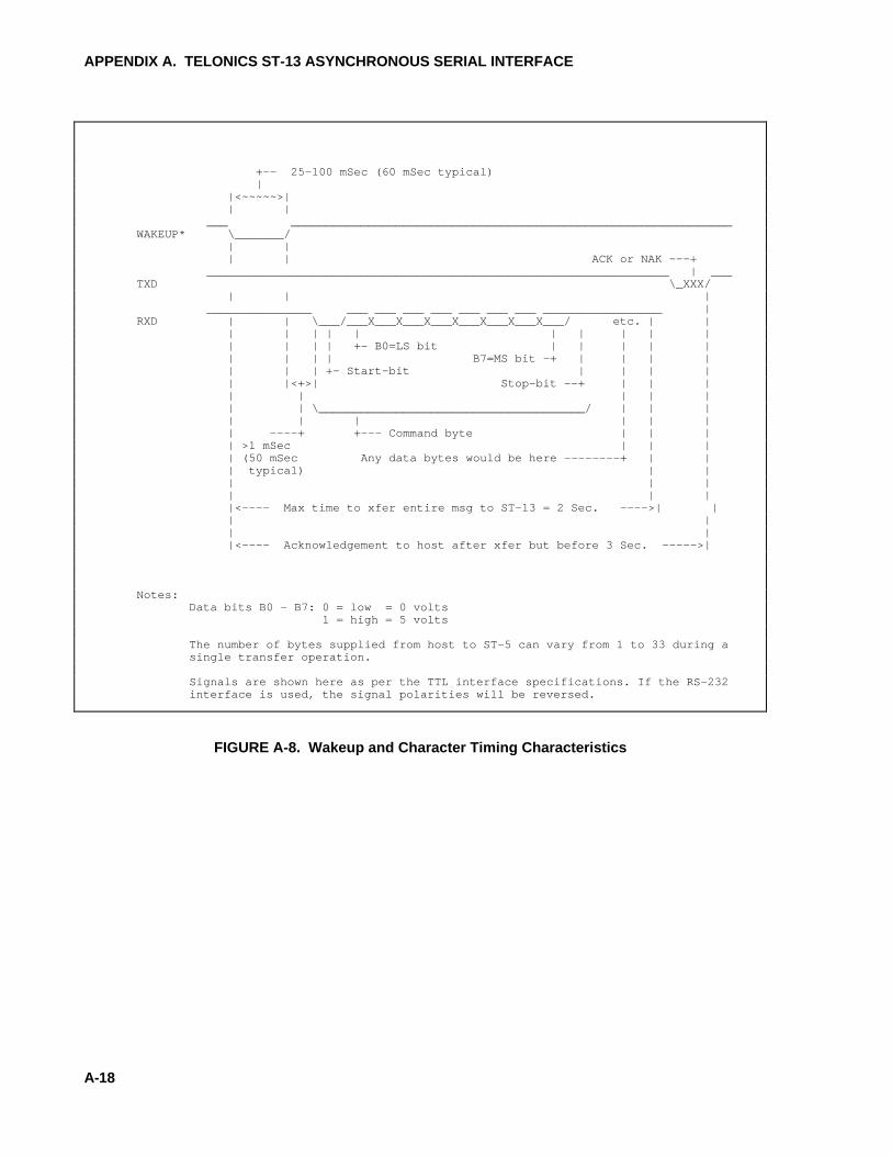
APPENDIX A. TELONICS ST-13 ASYNCHRONOUS SERIAL INTERFACE
A-18
+-- 25-100 mSec (60 mSec typical) | |<~~~~~>| | | ___ _______________________________________________________________WAKEUP* \_______/ | | | | ACK or NAK ---+ __________________________________________________________________ | ___TXD \_XXX/ | | | _______________ ___ ___ ___ ___ ___ ___ ___ _________________ |RXD | | \___/___X___X___X___X___X___X___X___/ etc. | | | | | | | | | | | | | | | | +- B0=LS bit | | | | | | | | | B7=MS bit -+ | | | | | | | +- Start-bit | | | | | |<+>| Stop-bit --+ | | | | | | | | | | \______________________________________/ | | | | | | | | | | ----+ +--- Command byte | | | | >1 mSec | | | | (50 mSec Any data bytes would be here --------+ | | | typical) | | | | | | | | |<---- Max time to xfer entire msg to ST-13 = 2 Sec. ---->| | | | | | |<---- Acknowledgement to host after xfer but before 3 Sec. ----->|
Notes:Data bits B0 - B7: 0 = low = 0 volts 1 = high = 5 volts
The number of bytes supplied from host to ST-5 can vary from 1 to 33 during asingle transfer operation.
Signals are shown here as per the TTL interface specifications. If the RS-232interface is used, the signal polarities will be reversed.
FIGURE A-8. Wakeup and Character Timing Characteristics

APPENDIX A. TELONICS ST-13 ASYNCHRONOUS SERIAL INTERFACE
A-19
|<--------- 3 sec max. -------->| |<-------- 3 sec max. ------>| | | | | | | | | | | | | __| _________________________________| _____________________________WAKEUP* \____/ \____/ | | | | | | | | | | | | | | | | _________ ____ _______________________ ____ ____________RXD \_XXX/ \_XXX/ \_XXX/ \_XXX/ | | | | | | | | | | | | | | | | | | | | | | | | | | | | | | | | | | | | | | | | _____________________________ |______________________________ _____TXD \_XXX/ \_XXX/ | | | | | | | | | | | | | | | | | | | | | | | | | | | | | | | | | | | | | | | | | Command Optional | ACK or | Command Optional | ACK or | Byte Data | NAK | Byte Data | NAK | Bytes | | Bytes | | | | | | | | | |<--- 2 sec max. --->| |<--- 2 sec max. --->| |<-------------->| | | +--- 100 mSec to 8 sec. Delay See section Command Initiation in text.
As an example, the first command could be a "Store Data" command and the secondcommand could be a "Transmit" command.
Signals are shown here as per the TTL interface specifications. If the RS-232interface is used, the signal polarities will be reversed.
FIGURE A-9. Multiple Command Timing

B-1
APPENDIX B. FINAL STORAGE FORMAT
CR10X data is formatted as either 2 byte LOResolution or 4 byte HI Resolution values. Thefirst two bytes of an Output Array contain a uniquecode (FC Hex) noting the start of the Output Arrayand the Output Array ID, followed by the 2 or 4byte data values. At the end of the data sent inresponse to the telecommunications F command a2 byte signature is sent (see below).
Representing the bits in the first byte of eachtwo byte pair as ABCD EFGH (A is the mostsignificant bit, MSB), the byte pairs aredescribed here.
LO RESOLUTION FORMAT - D,E,F, NOT ALL ONES
Bits Description
A Polarity, 0 = +, 1 = -.B, C Decimal locators as defined below.D-H plus 13 bit binary value (D=MSB).second Largest possible number without D,
E, and F all 1 is 7167,byte but CSI defines the largest
allowable range as 6999.
The decimal locators can be viewed as anegative base 10 exponent with decimallocations as follows:
B C Decimal Location
0 0 XXXX.0 1 XXX.X1 0 XX.XX1 1 X.XXX
DATA TYPE WHEN D,E,F, ALL EQUAL ONE
If D, E, and F are all ones, the data type isdetermined by the other bits as shown below. Ximplies a "don't care" condition; i.e., the bit canbe either 1 or 0 and is not used in the decodedecision.
A B C D E F G H DATA TYPE AND SECOND BYTE FORMAT
1 1 1 1 1 1 X X A,B,C, = 1 - Start of Output Array, G & H are the mostsignificant bits of the Output Array ID. All 8 bits of the2nd byte are also included in the ID.
X X 0 1 1 1 X X C = 0 - First byte of a 4 byte value.
0 0 1 1 1 1 X X A,B = 0; C = 1 - Third byte of a 4 byte value.
0 1 1 1 1 1 1 1 A = 0; remaining bits = 1 - First byte of a 2 byte"dummy" word. The CR10X always transmits a 0 forthe 2nd byte, but the word can be decoded on the basisof the 1st byte only.