srèv - ipen.br
TRANSCRIPT
*TU»ft**ftC»r*^!« ' V
p..
IV*-"
tv*"'..
Srèv
0
We regret that some of the pages in the microfiche copy of this report may not be up to the proper legibility standards, even though the best possible copy was used for preparing the master fiche.
DATA ACQUISITION SYSTEM FOR TWO-PARAMETER
NEUTRON SPECTROMETRY
L. MEWISSEN
BLG 466

L. MEWISSEN BIG 466 (June 1972)
DATA ACQUISITION SYSTEM FOR TWO-PARAMETER NEUTRON
SPECTROMETRY
Summery A computer programme of a data acquisition system for two-parameter neutron spectrometry is described, with flowcharts of the different phases. It has been implemented for a 8K co - .xjter, 16 bits word length, interfaced with a 256K disc memory.
The operating procedure necessary to run the programme is summarized. The Assembler listing of the programme is also given in annex.
L. MEWISSEN BLG 466 (June 1972)
DATA ACQUISITION SYSTEM FOR TWO-PARAMETER NEUTRON
SPECTROMETRY
Résumé Un programme de computer avec les flowcharts des phases différentes, a été décrite, pour faire des mesures à deux dimensions en spectrométrie neutronique. Il a été développé pour un computer de 8K, 16 bits largeur des mots, couplé à une mémoire-disque de 256K.
La procédure pour opérer le programme a été expliquée. *En annexe on trouve aussi la liste du programme en instructions Assembler.
L. MEWISSEN BLG 466 (June 1972)
DATA ACQUISITION SYSTEM FOR TWO-PARAMETER NEUTRON
SPECTROMETRY
Samenvatting Een computerprogramma, om twee parametermetingen uit te voeren in neutronenspektrometrie, is beschreven aan de hand van de flowcharts van de samenstellende delen. Het werd opgesteld voor een 8K computer, 16 bits woordlengte, gekoppeld aan een schijfgeheugen van 256K.
De werkwijze om het programma uit te voeren werd aangegeven. De lijst van de instrukties, in de Assemblertaal van de computer, bevindt zich in bijlage.
Contents
1. Introduction
2. Organization of the supervisor programme
2.1. Initiation phase
2.2. Interrupt routine entry
2.3. Analysis of the address pairs
2.4. Routine ACORD to compose the histogramme
3. Efficiency and timing considerations
4. General procedures in the programme
5. Operating instructions
6. Supplementary routines and remarks
7. Bibliographic references and figure captions
Annex : Assembler listing of the programme
1. Introduction
The measurement of prompt Y~ravs following neutron capture has been applied for the past fifteen years as the preferred method to determine capture cross-sections as a function of neutron energy. We have implemented for such measurements a two-dimensional data acquisition system, based on a small computer, interfaced with a disc memory. The specifications of the 2115 A Hewlett-Packard computer are the following : memory size of 8192 (8K) words. Word length 16 bits and a cycle time of 2 us. The computer has 7 working registers and a set of 70 machine instructions is available in the Assembler language of the HP 7115 A. The Applied Magnetics Corporation (A.M.C.) disc is a fixed head per track memory system, using a single 12 inch diameter cobalt plated disc. There are 16 head modules, with each 8 tracks or 128 tracks in total. Each track consists of 32 sectors, each sector has 64 words. The total capacity of the disc is 256 K words and the mean access-time is 8.3 ms. With this system, the Moxon-Rae detection approach to spectral independence, can be generalized in the total weighting technique, proposed first by Meier-Leibnitz. By this technique most y~ray detector systems can be adapted to give exactly the required response, at the expense of recording the pulse-height spectrum. By assigning an importance or weight to detector events, which depends on the pulse-height alone, the average response can be made proportional to the total "y-energy emitted by the sample. We intend to utilize this system for measurements of the capture cross-section of 23eU, with a pair of fluorocarbon liquid scintillators.
2. Organization of the supervisor programme
The source tape of the programme, written in Assembler language of the HP 2115 A computer is subdivided into four paper tapes, which constitute the different parts of the supervisor programme. This division is rather arbitrary and based on four phases of the process :
- INIT ,.see annex page 3 statement No. 1) : in this phase all control elements and counters are initiated ;
- ANALYSIS (annex page 5 statement No. 13 : contains the storing of the buffered time-of-flight addresses in 32 pulse-height groups and the swapping to disc, each time a sector is filled. The reorganization of the core, when a track of the temporary storage area on disc is filled, to prepare the updating of the histogramme, is also executed in this phase of the programme j
- ACORD (annex page 8 statement No. 1) : this part of the programme is incorporated as a subroutine in the analysis part. The updating of each time-of-f light address stored in the entry buffers, in order to obtain the frequency distribution, is executed in this subroutine ,•
- ENTRY [annex page 9 statement No. 1) : this subroutine is entered via the trapcell to treat each event arriving in the detectors. It stores the address pairs in interrupt, this means that the sorting programme resumes execution after the storage of each event in an entry buffer.
2.1. INIT Routine
In this part of the supervisor programme all the core buffers and also the disc storage are cleared, when the option to start a new run* has been chosen. All the counters for buffer areas are initiated and the resolution factors, fcr the accordeon system with variable channel width, are stored
by the programme. At the end of the routine INIT a check of the location "full" is executed. This can be considered as the main part of the supervisor programme.
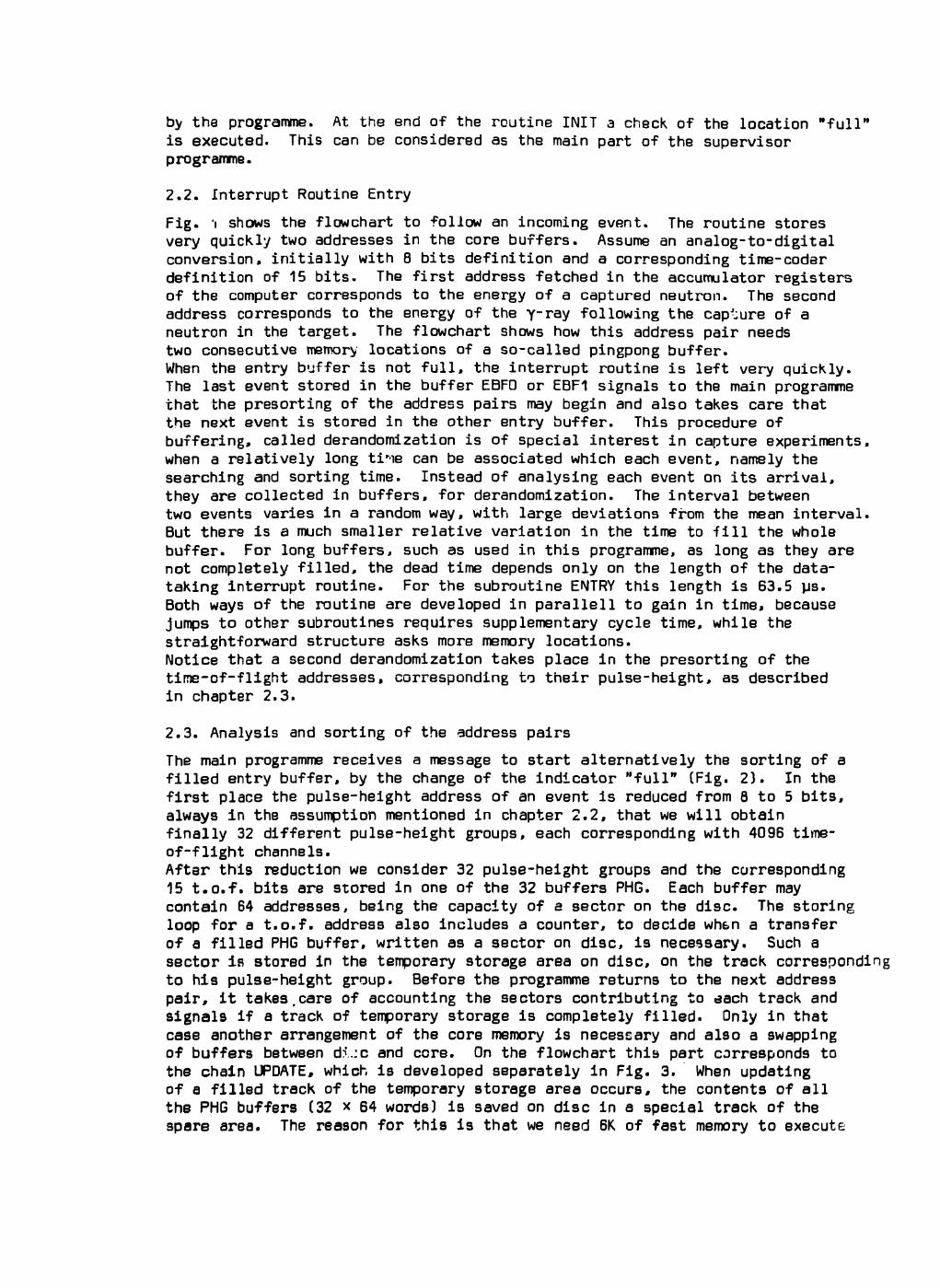
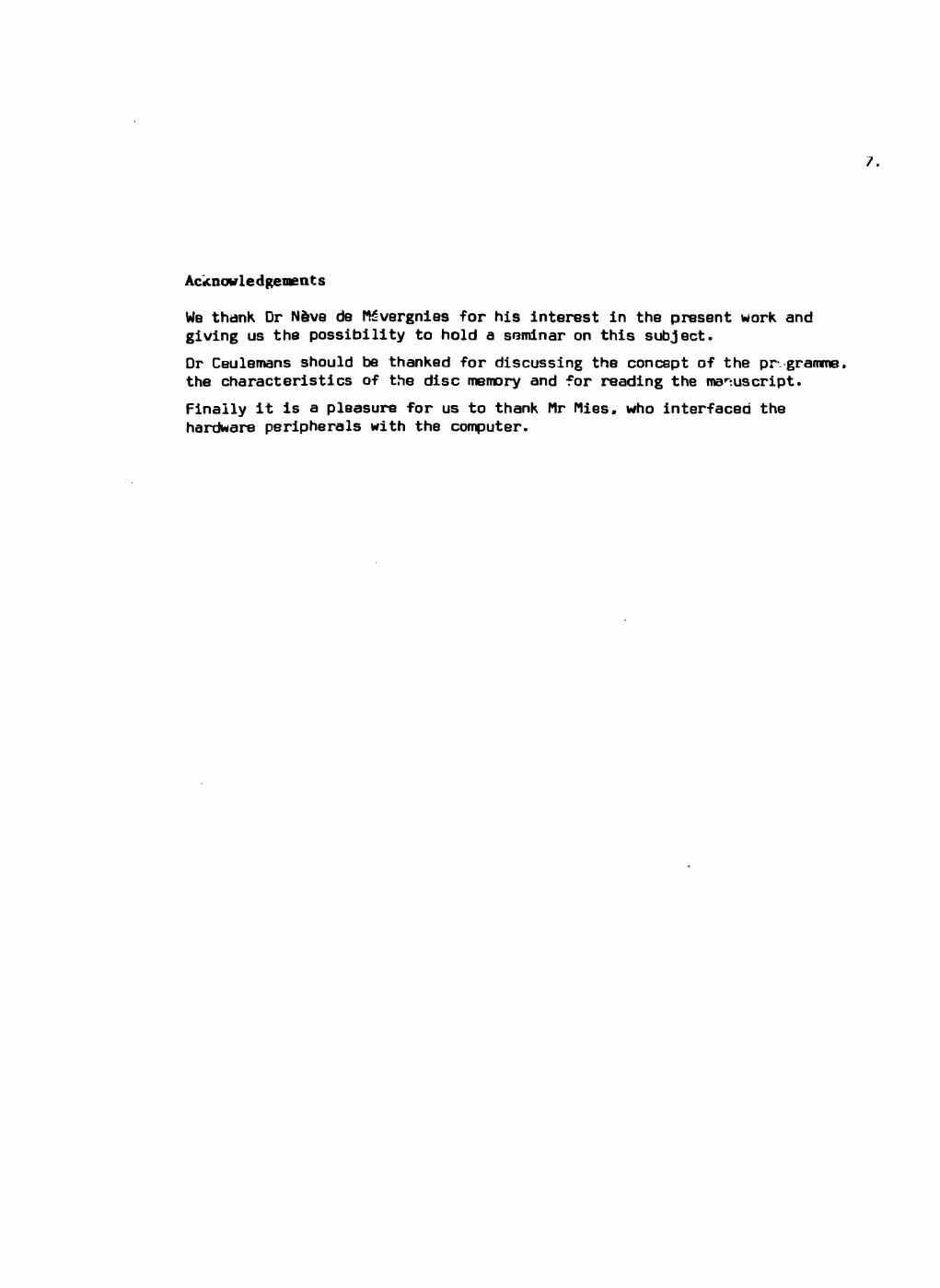
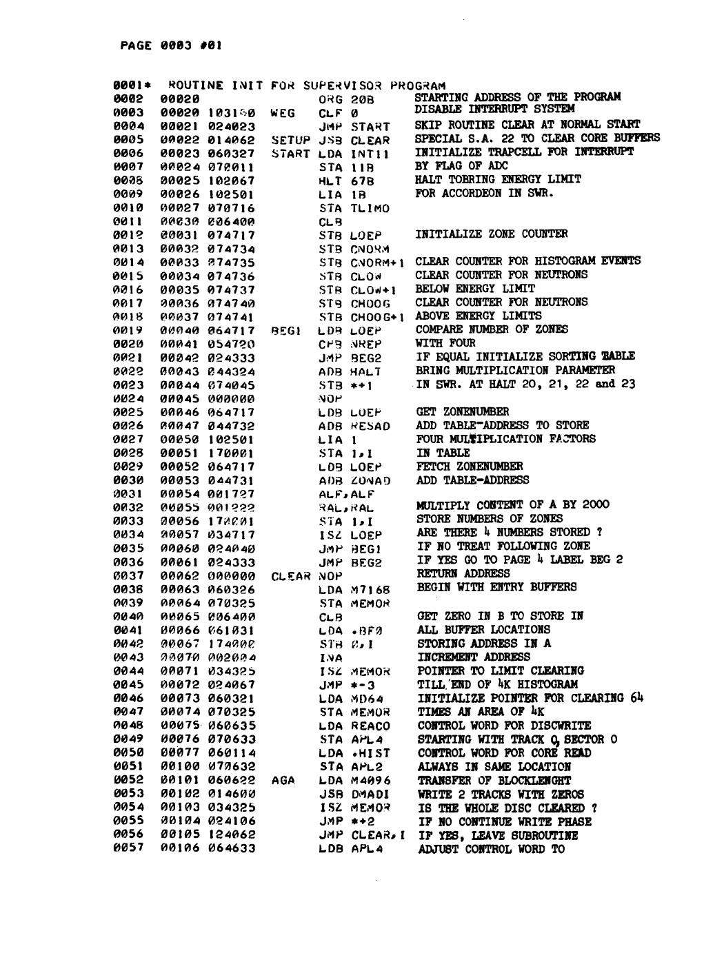
2.2. Interrupt Routine Entry
Fig. 'i shows the flowchart to follow an incoming event. The routine stores very quickly two addresses in the core buffers. Assume an analog-to-digital conversion, initially with 8 bits definition and a corresponding time-coder definition of 15 bits. The first address fetched in the accumulator registers of the computer corresponds to the energy of a captured neutron. The second address corresponds to the energy of the yray following the capture of a neutron in the target. The flowchart shows how this address pair needs two consecutive memory locations of a so-called pingpong buffer. When the entry buffer is not full, the interrupt routine is left very quickly. The last event stored in the buffer EBFO or EBF1 signals to the main programme that the presorting of the address pairs may begin and also takes care that the next event is stored in the other entry buffer. This procedure of buffering, called derandomization is of special interest in capture experiments, when a relatively long ti-ie can be associated which each event, namely the searching and sorting time. Instead of analysing each event on its arrivai, they are collected in buffers, for derandomization. The interval between two events varies in a random way, with large deviations from the mean interval. But there is a much smaller relative variation in the time to fill the whole buffer. For long buffers, such as used in this programme, as long as they are not completely filled, the dead time depends only on the length of the data-taking interrupt routine. For the subroutine ENTRY this length is 63.5 us. Both ways of the routine are developed in parallell to gain in time, because jumps to other subroutines requires supplementary cycle time, while the straightforward structure asks more memory locations. Notice that a second derandomization takes place in the presorting of the time-of-flight addresses, corresponding to their pulse-height, as described in chapter 2.3.
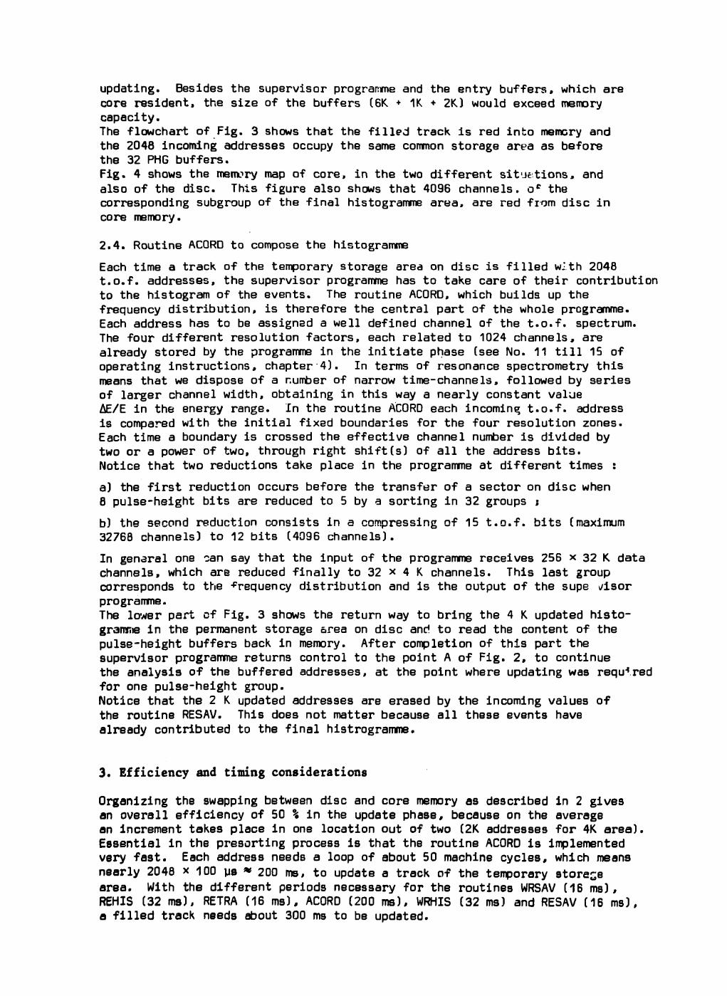
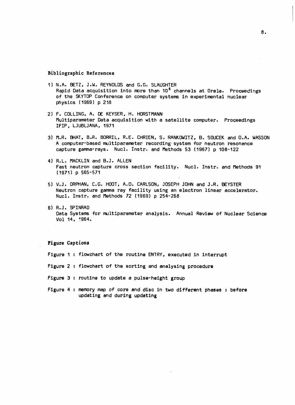
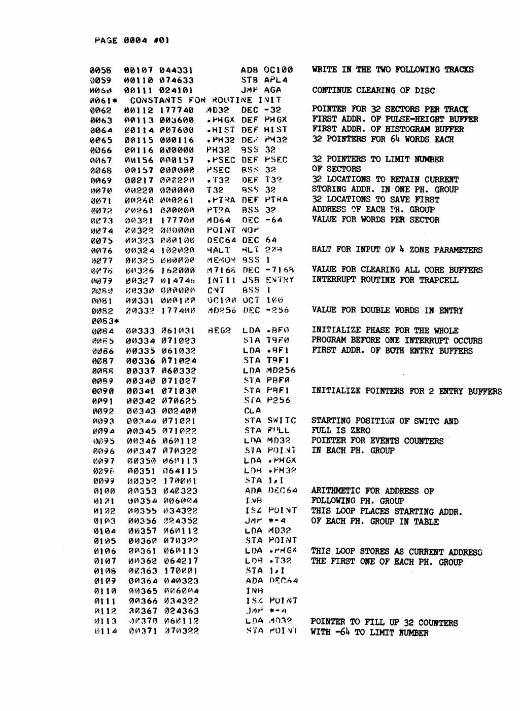
2.3. Analysis and sorting of the address pairs
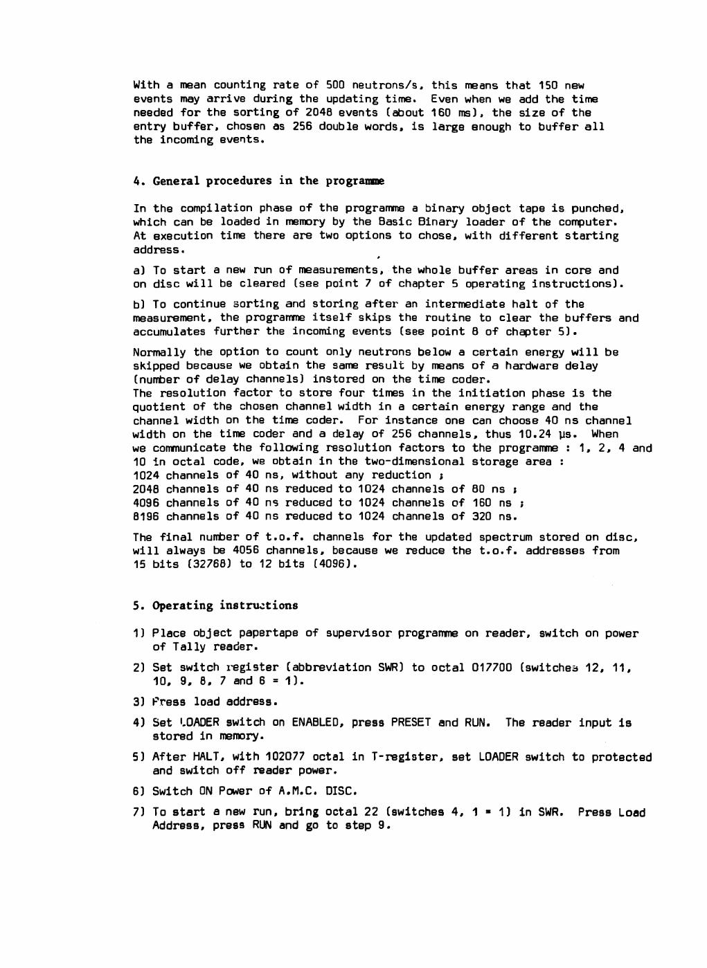
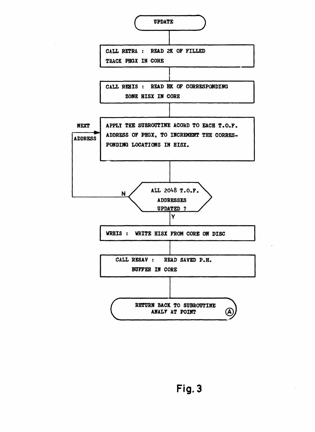
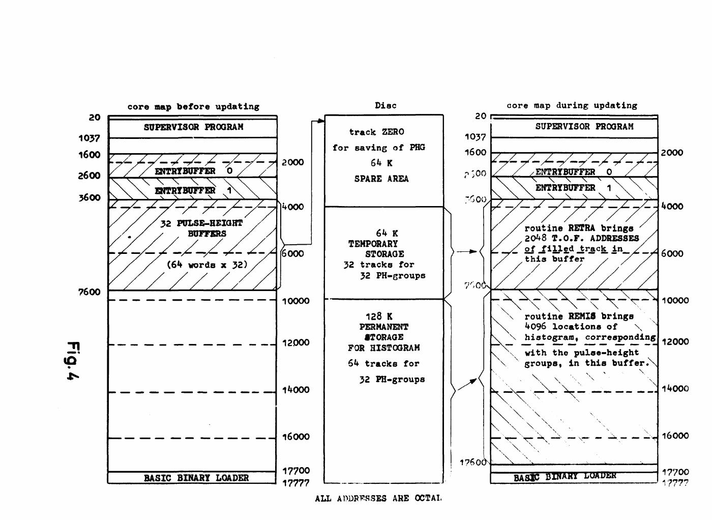
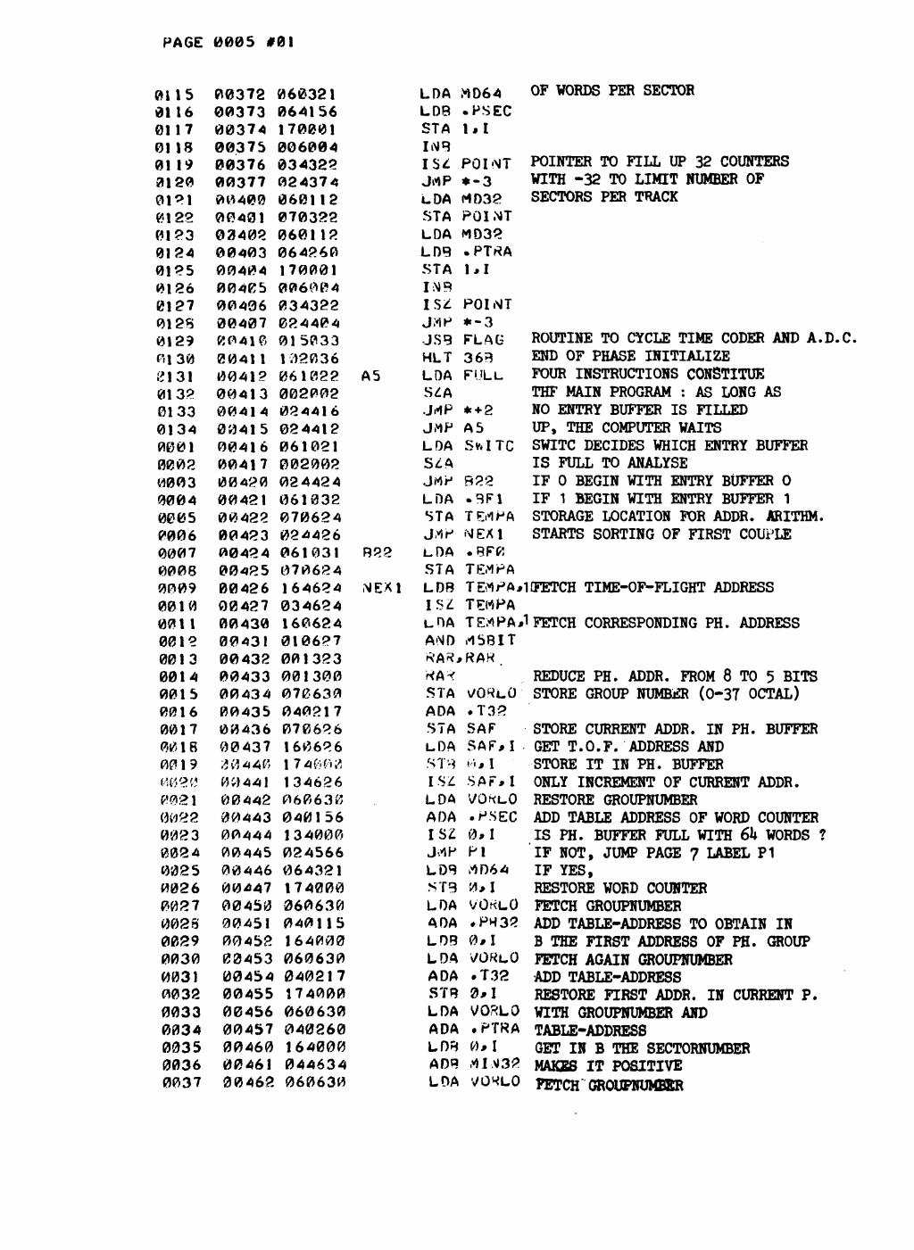
The main programme receives a message to start alternatively the sorting of a filled entry buffer, by the change of the indicator "full" (Fig. 2). In the first place the pulse-height address of an event is reduced from 8 to 5 bits, always in the assumption mentioned in chapter 2.2, that we will obtain finally 32 different pulse-height groups, each corresponding with 4096 time-of-f light channels. After this reduction we consider 32 pulse-height groups and the corresponding 15 t.o.f. bits are stored in one of the 32 buffers PHG. Each buffer may contain 64 addresses, being the capacity of a sector on the disc. The storing loop for a t.o.f. address also includes a counter, to decide wh&n a transfer of a filled PHG buffer, written as a sector on disc, is necessary. Such a sector is stored in the temporary storage area on disc, on the track corresponding to his pulse-height group. Before the programme returns to the next address pair, it takes.care of accounting the sectors contributing to each track and signals if a track of temporary storage is completely filled. Only in that case another arrangement of the core memory is necessary and also a swapping of buffers between d>'.:c and core. On the flowchart this part corresponds to the chain UPDATE, which is developed separately in Fig. 3. When updating of a filled track of the temporary storage area occurs, the contents of all the PHG buffers (32 x 64 words) is saved on disc in a special track of the spare area. The reason for this is that we need 6K of fast memory to execute
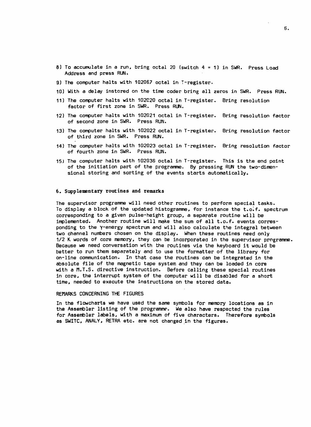
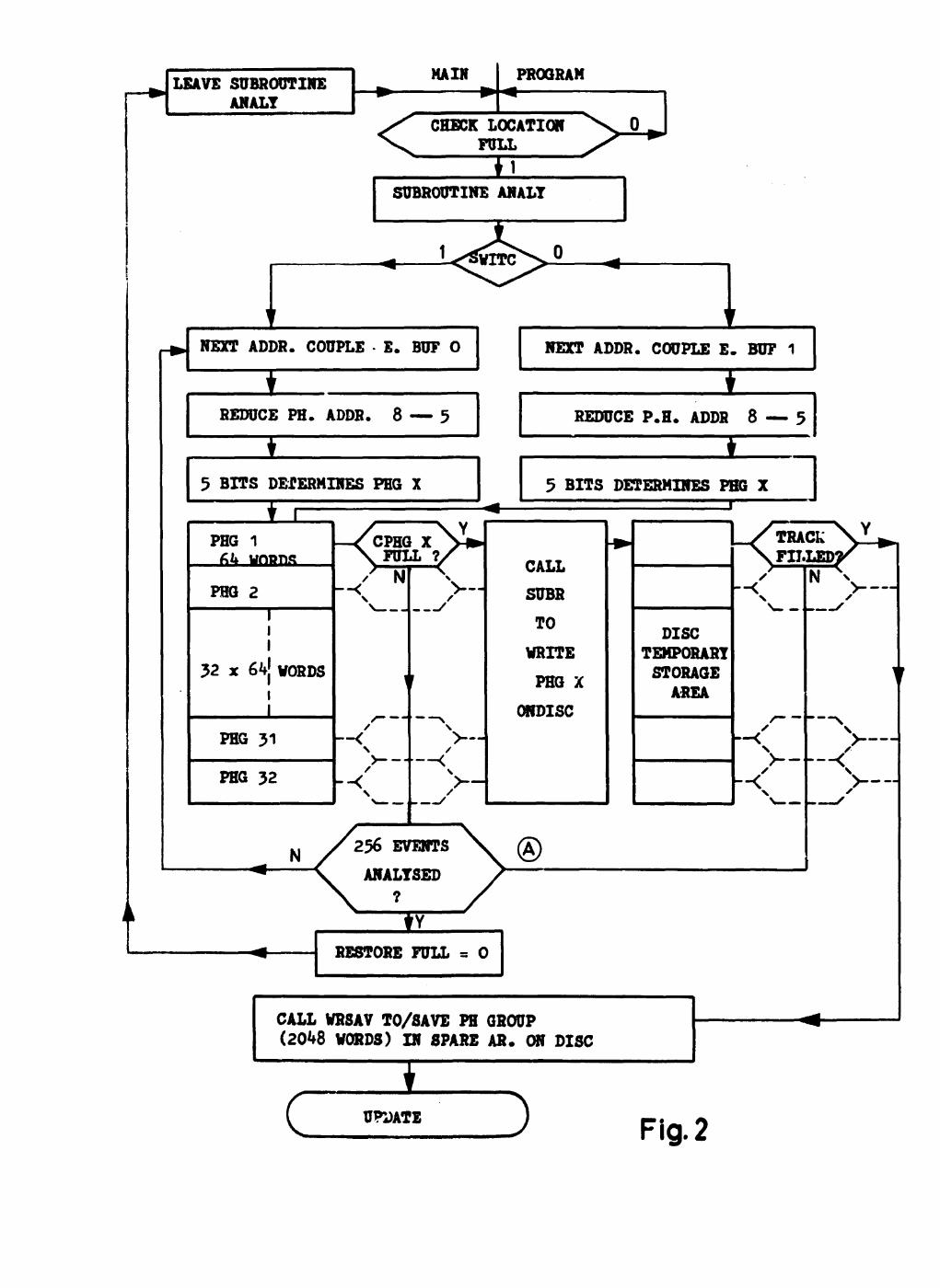
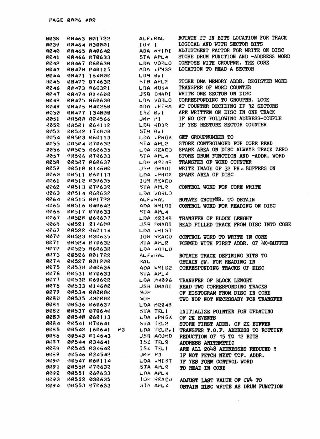
updating. Besides the supervisor programme and the entry buffers, which are core resident, the size of the buffers (6K + 1K. + 2K) would exceed memory capacity. The flowchart of Fig. 3 shows that the filled track is red into memcry and the 2048 incoming addresses occupy the same common storage area as before the 32 PHG buffers. Fig. 4 shows the memory map of core, in the two different situations, and also of the disc. This figure also shows that 4096 channels. oc the corresponding subgroup of the final histogramme area, are red from disc in core memory.
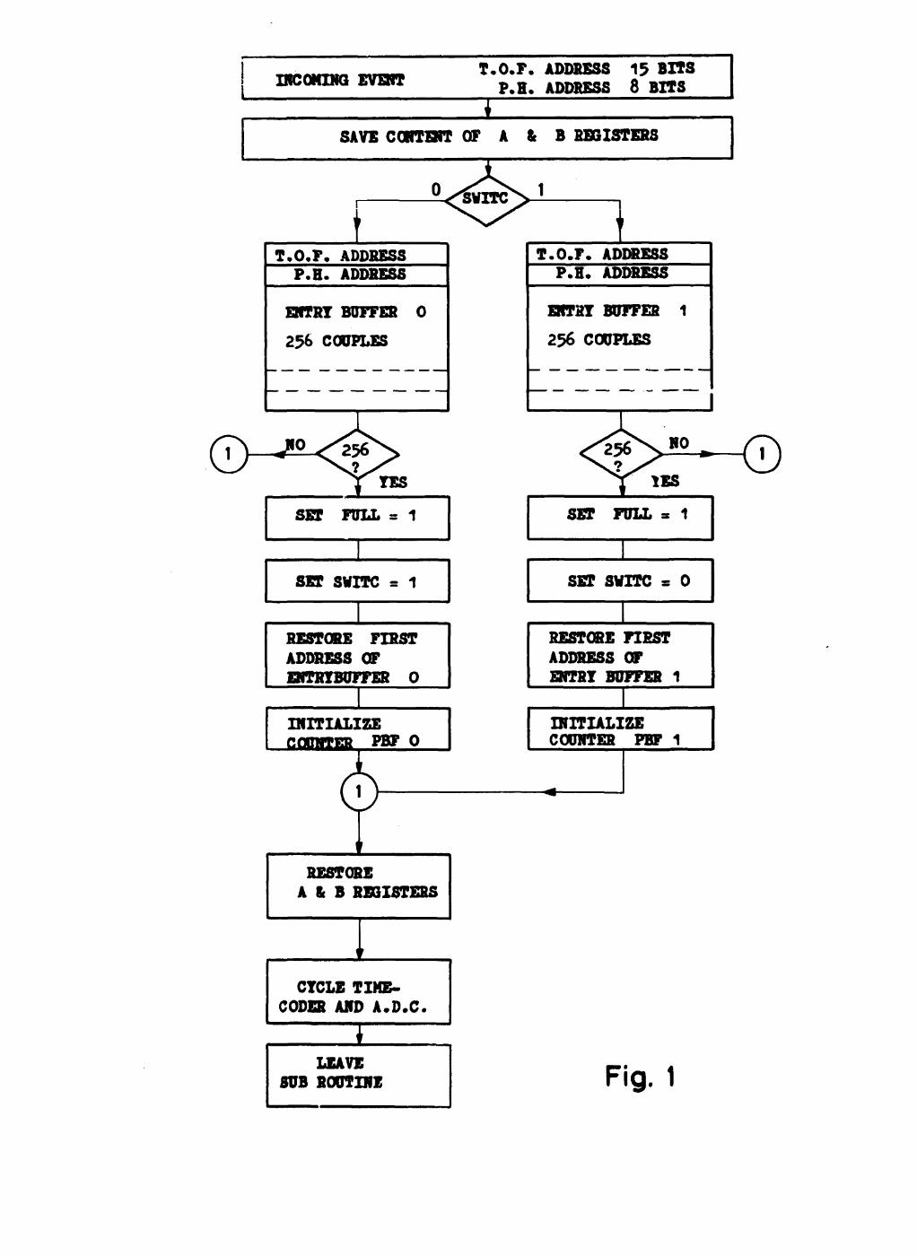
2.4. Routine ACORD to compose the histogramme
Each time a track of the temporary storage area on disc is filled with 2048 t.o.f. addresses, the supervisor programme has to take care of their contribution to the histogram of the events. The routine ACORD, which builds up the frequency distribution, is therefore the central part of the whole programme. Each address has to be assigned a well defined channel of the t.o.f. spectrum. The four different resolution factors, each related to 1024 channels, are already stored by the programme in the initiate phase (see No. 11 till 15 of operating instructions, chapter 4). In terms of resonance spectrometry this means that we dispose of a number of narrow time-channels, followed by series of larger channel width, obtaining in this way a nearly constant value AE/E in the energy range. In the routine ACORD each incoming t.o.f. address is compared with the initial fixed boundaries for the four resolution zones. Each time a boundary is crossed the effective channel number is divided by two or a power of two, through right shift(s) of all the address bits. Notice that two reductions take place in the programme at different times :
a) the first reduction occurs before the transfer of a sector on disc when 8 pulse-height bits are reduced to 5 by a sorting in 32 groups ;
b) the second reduction consists in a compressing of 15 t.o.f. bits (maximum 32768 channels) to 12 bits (4096 channels).
In genaral one can say that the input of the programme receives 256 x 32 K data channels, which are reduced finally to 32 x 4 K channels. This last group corresponds to the -frequency distribution and is the output of the supe \/isor programme. The lower part of Fig. 3 shows the return way to bring the 4 K updated histogramme in the permanent storage orea on disc and to read the content of the pulse-height buffers back in memory. After completion of this part the supervisor programme returns control to the point A of Fig. 2, to continue the analysis of the buffered addresses, at the point where updating was required for one pulse-height group. Notice that the 2 K updated addresses are erased by the incoming values of the routine RESAV. This does not matter because all these events have already contributed to the final histrogramme.
3. Efficiency and timing considerations
Organizing the swapping between disc and core memory as described in 2 gives an overall efficiency of 50 % in the update phase, because on the average an increment takes place in one location out of two (2K. addresses for 4K area). Essential in the presorting process is that the routine ACORD is implemented very fast. Each address needs a loop of about 50 machine cycles, which means nearly 2048 x 100 us * 200 ms, to update a track of the temporary storere area. With the different periods necessary for the routines WRSAV (16 ms), REHIS (32 ms), RETRA (16 ms), ACORD (200 ms), WRHIS (32 ms) and RESAV (16 ms), a filled track needs about 300 ms to be updated.
With a mean counting rate of 500 neutrons/s, this means that 150 new events may arrive during the updating time. Even when we add the time needed for the sorting of 2048 events (about 160 ms), the size of the entry buffer, chosen as 256 double words, is large enough to buffer all the incoming events.
4. General procedures in the programme
In the compilation phase of the programme a binary object tape is punched, which can be loaded in memory by the Basic Binary loader of the computer. At execution time there are two options to chose, with different starting address.
a) To start a new run of measurements, the whole buffer areas in core and on disc will be cleared (see point 7 of chapter 5 operating instructions).
b) To continue sorting and storing after an intermediate halt of the measurement, the programme itself skips the routine to clear the buffers and accumulates further the incoming events (see point 8 of chapter 5).
Normally the option to count only neutrons below a certain energy will be skipped because we obtain the same result by means of a hardware delay (number of delay channels) instored on the time coder. The resolution factor to store four times in the initiation phase is the quotient of the chosen channel width in a certain energy range and the channel width on the time coder. For instance one can choose 40 ns channel width on the time coder and a delay of 256 channels, thus 10.24 us. When we communicate the following resolution factors to the programme : 1, 2, 4 and 10 in octal code, we obtain in the two-dimensional storage area : 1024 channels of 40 ns, without any reduction ; 2048 channels of 40 ns reduced to 1024 channels of 80 ns ; 4096 channels of 40 ns reduced to 1024 channels of 160 ns ; 8196 channels of 40 ns reduced to 1024 channels of 320 ns.
The final number of t.o.f. channels for the updated spectrum stored on disc, will always be 4056 channels, because we reduce the t.o.f. addresses from 15 bits (32766) to 12 bits (4096).
5. Operating instructions
1) Place object papertape of supervisor programme on reader, switch on power of Tally reader.
2) Set switch register (abbreviation SWR) to octal 017700 (switches 12, 11, 10, 9, 8» 7 and 6 = 1).
3) Press load address.
4) Set LOADER switch on ENABLED, press PRESET and RUN. The reader input is stored in memory.
5) After HALT, with 102077 octal in T-register, set LOADER switch to protected and switch off reader power.
6) Switch ON Power of A.M.C. DISC.
7) To start a new run, bring octal 22 (switches 4, 1 - 1 ) in SWR. Press Load Address, press RUM and go to step 9.
6.
8) To accumulate in a run, bring octal 20 (switch 4 = 1) in SWR. Press Load Address and press RUN.
9) The computer halts with 102067 octal in T-register.
10) With a delay instored on the time coder bring all zeros in SWR. Press RUN.
11) The computer halts with 102020 octal in T-register. Bring resolution factor of first zone in SWR. Press RUN.
12) The computer halts with 102021 octal in T-register. Bring resolution factor of second zone in SWR. Press RUN.
13) The computer halts with 102022 octal in T-register. Bring resolution factor of third zone in SWR. Press RUN.
14) The computer halts with 102023 octal in T-register. Bring resolution factor of fourth zone in SWR. Press RUN.
15) The computer halts with 102036 octal in T-register. This is the end point of the initiation part of the programme. By pressing RUN the two-dimensional storing and sorting of the events starts automatically.
6. Supplementary routines and remarks
The supervisor programme will need other routines to perform special tasks. To display a block of the updated histogramme, for instance the t.o^f. spectrum corresponding to a given pulse-height group, a separate routine will be implemented. Another routine will make the sum of all t.o.f. events corresponding to the yenergy spectrum and will also calculate the integral between two channel numbers chosen on the display. When these routines need only 1/2 K words of core memory, they can be incorporated in the supervisor programme, Because we need conversation with the routines via the keyboard it would be better to run them separately and to use the formatter of the library for on-line communication. In that case the routines can be integrated in the absolute file of the magnetic tape system and they can be loaded in core with a M.T.S. directive instruction. Before calling these special routines in core, the interrupt system of the computer will be disabled for a short time, needed to execute the instructions on the stored data.
REMARKS CONCERNING THE FIGURES
In the flowcharts we have used the same symbols for memory locations as in the Assembler listing of the programme. We also have respected the rules for Assembler labels, with a maximum of five characters. Therefore symbols as SWITC, ANALY, RETRA etc. are not changed in the figures.
7.
Acknowledgements
We thank Dr Nève de Mévergnies for his interest in the present work and giving us the possibility to hold a seminar on this subject.
Dr Ceulemans should be thanked for discussing the concept of the pr-. gramme, the characteristics of the disc memory and for reading the manuscript.
Finally it is a pleasure for us to thank Mr Mies, who interfaced the hardware peripherals with the computer.
8.
Bibliographic References
1) N.A. BETZ, J.W. REYNOLDS and G.G. SLAUGHTER Rapid Data acquisition into more than 105 channels at Orela. Proceedings of the SKYTOP Conference on computer systems in experimental nuclear physics (1969) p 216
2) F. COLLING, A. DE KEYSER. H. HORSTMANN Multiparameter Data acquisition with a satellite computer. Proceedings IFIP, LJUBLJANA» 1971
3) M.R. BHAT. B.R. BORRIL, R.E. CHRIEN, S. RANKOWITZ, B. SOUCEK and O.A. WASSON A computer-based multiparameter recording system for neutron resonance capture gamma-rays. Nucl. Instr. and Methods 53 (1967) p 108-122
4) R.L. MACKLIN and B.J. ALLEN Fast neutron capture cross section facility. Nucl. Instr. and Methods 91 (1971) p 565-571
5) V.J. ORPHAN, C.G. HOOT. A.D. CARLSON, JOSEPH JOHN and J.R. BEYSTER Neutron capture gamma ray facility using an electron linear accelerator. Nucl. Instr. and Methods 72 (1969) p 254-268
6) R.J. SPINRAD Data Systems for multiparameter analysis. Annual Review of Nuclear Science Vol 14, 1964.
Figure Captions
Figure 1 : flowchart of the routine ENTRY, executed in interrupt
Figure 2 : flowchart of the sorting and analysing procedure
Figure 3 : routine to update a pulse-height group
Figure 4 : memory map of core and disc in two different phases : before updating and during updating
INCOMING EVENT T.O.F. ADDRESS 15 BITS
P.H. ADDRESS 8 BITS
I SAVE CONTENT OF A & B REGISTERS
i T.O.F. ADDRESS P.H. ADDRESS
BfTRY BUFFER O
2% COUPLES
J YES
SET FULL = 1
SET SVITC = 1
RESTORE FIRST ADDRESS OF ENTRYBUFFER O
INITIALIZE CCmiTER PKF O
RESTORE A & B RÉSISTERS
I CYCLE TIME-
CODER AND A.D.C.
I LEAVE
SUB ROUTINE
1 T.O.F. ADDRESS
P.H. ADDRESS
ENTRY BUFFER 1
256 COUPLES
SET FULL
SET svrrc = o
RESTORE FIRST ADDRESS OF ENTRY BUFFER 1
INITIALIZE COUNTER PBF 1
Fig. 1
t
LEAVE SUBROUTINE ANALT
NAIN
<
PROGRAM
CHECK LOCATION FULL n
i NEXT ADDR. COUPLE E. BUT O
Ï REDUCE PH. ADDS. 8 — 5
Ï 5 BITS DEf ERMINES PHG X
T7
NEXT ADDR. COUPLE E. BUF 1
*
REDUCE P.H. ADDR 8 — 5
•
5 BITS DETERMINES PHG X i
PHG 1 6L unnns
PHG 2
32 x 6*fj WORDS
PHG 31
PHG 32
H CPHG X FULL ?.
N ^
V -
N
CALL
SUBR
TO
WRITE
PHG X
OifDISC
K TRACK \ L ^ . FILLED^ ^
DISC TEMPORARY STORAGE AREA
--<
236 EVENTS
ANALYSED ®
)
) C > — -
RESTORE FULL = O
CALL WRSAV TO/SAVE PH GROUP (2048 WORDS) IN SPARE AR. ON DISC
C ï
UPDATE } Fig. 2
NEXT
ADDRESS
CALL RETRA : READ 2K OF FILLED
TRACK PHGX IN CORE
CALL REHIS : READ fiK OF CORRESPONDING
ZONE HISX IN CORE
APPLY THE SUBROUTINE ACORD TO EACH T.O.F.
ADDRESS OF PHGX, TO INCREMENT THE CORRES.
PONDING LOCATIONS IN HISX.
ALL 2048 T.O.F
ADDRESSES
UPDATED ?
VRHIS : VRITE HISX FROM CORE ON DISC
CALL RESAV : READ SAVED P.H.
BUFFER IN CORE
(
RETURN BACK TO SUBROUTINE ANALT AT POINT (A)
^
Fig. 3
core map before updating Disc 20
1037
1600
2600
3600
SUPERVISOR PROGRAM
ENTRYBUFFER 0 V V V V \
7-
7600
ENTRTBDFFER 1
2000
V A/--/-. PULSE-HEIGHT
BUFFERS
(64 words x 32)
21
BASIC BINARY LOADER
4000
6000
10000
12000
14000
16000
17700 17777
track ZERO
for 6aving of PHG
64 K
SPARE AREA
64 K TEMPORARY
STORAGE 32 tracks for
32 PH-groups
128 K PERMANENT 1T0RAGE
FOR HISTOGRAM
64 tracks for
32 PH-groups
core map during updating 20 n
1037
1600
psoo
%QQ/^±7Z
S (
1760&
SUPERVISOR PROGRAM
-r7-/ENTRYBUFFER 0 T — v \ \ y ENTRYBUFFER —A -/- - 4ooo
routine RETRA brings 2048 T.O.F. ADDRESSES 2Î Ji±±S£ J rJlciL in. t h i s buffer
\ routine REMIS brings 4096 locations of \
v x histogram, corresponding.12000 with the pulse-height groups, in this buffer. \
\.
\
\
,-\-- .__• x. 14000
\. ^
\ -^
BASIC ÓINAHY LUADKK
2000
6000
10000
16000
17700 17777
ALL AttDBtfSSES ARE OCTAL
PAGE 9001
0001 A5 AGA B22 8F0 BF1 CNT CW1 LOW PI P3 P4 SAF T32 TOF WEG • BF0 .BF1 .HIST .PH32 .PHGX • PSEC .PTRA .T32 ACORD APL2 APL4 BEG1 BEG2 CHOOG CLEAR CLOW CNORfl DEC64 DMADI ENTRY FLAG FULL HALT HIST HOOG INT 11 LEAF1 LOEP M2048 .M 409 6 ,1581T .17168 .1D256 MD32 (1D64 MErtOR (1IN32 NEXl NREP OC100 P256
ASHB#A*B*L#T 000412 000101 000424 001600 002600 000330 000621 000706 000566 000542 000573 000626 000220 000010 000020 001031 001032 000114 000115 000113 000156 000260 000217 000643 000632 000633 00004C 000333 000740 000062 000736 000734 000323 000600 000746 001033 001022 000324 007600 000712 000327 000773 000717 000637 000622 000627 000326 000332 000112 000321 000325 000634 000426 000720 000331 000625
PAGE 0 0 0 2
PART2 PBF0 PBF1 PH32 PHGX PHOOG POINT PS EC PTRA REACO RESAD RESTA SACW3 SAtfEA SAVEB SECiMR SETUP SKI F START STORA STORE STOTA SWITC T8F0 T9F1 TELl TEL2 TEMPA TLIfMO v/ERGL VORLO WRID2 v»RIDI ZONAD ZOTAB •4i NO
001000 001027 001030 000116 003600 004011 000322 000157 000261 000635 000732 000725 000623 001025 001026 000631 000022 000663 000023 000733 000676 000721 001021 001023 001024 000640 000641 000624 000716 000652 000630 000636 000642 000731 000742 ERRORS*
PAGE 0003 #01
0001* 0002 0003 0004 0005 0006 0007 0003 0009 0010 0011 0012 0013 0014 0015 0016 0017 0018 0019 0020 0021 0022 0023 0024 0025 0026 0027 0028 0029 0030 0031 0032 0033 0034 0035 0036 0037 0038 0039 0040 0041 0042 0043 0044 0045 0046 0047 0048 0049 0050 0051 0052 0053 0054 0055 0056 0057
ROUTI 00020 00020 00021 00022 00023 00024 00025 00026 00027 00030 0003! 00032 00033 00034 00035 00036 00037 00040 00041 00042 00043 00044 00045 00046 00047 00050 00051 00052 00053 00054 00055 00056 00057 00060 00061 00062 00063 00064 00065 00066 00067 00070 00071 00072 00073 00074 00075 00076 00077 00100 00101 00102 00103 00104 00105 00106
NE IMIT FOR SUPERVISOR PROGRAM
1031'v0 024023 014062 060327 070011 102067 102501 070716 006400 074717 074734 074735 074736 074737 0747 40 074741 064717 05472O 024333 044324 074045 000000 064717 044732 102501 170001 064717 044731 001727 001222 170K01 034717 024040 024333 000000 060326 070325 006400 061031 174000 0020(94 034325 024067 060321 070325 060635 070633 060114 070632 060622 014600 034325 024106 124062 064633
WEG
SETUP START
8EG1
CLEAR
AGA
ORG CLF JMP J SB LOA STA HLT LIA STA CL 8 ST8 STB ST8 ST8 STB ST 8 STB LD8 CHB JtfP ADB ST3 NOP LDB ADB LIA STA L09 ADB ALF* -*AL, STA IS£ Jrtp JMP NOP LDA STA CUB LDA STB IN A IS£ JMP LOA STA LOA STA LDA STA LDA JSB ISZ JtfP JrtP LDB
20B 0 START CLEAR INTU 1 18 67B IB TLIMO
LOEP CNORri CNORM+1 CLOW CLO*l*l CHOOG CHOOG-M L.OEP tfREP BEG2 HALT **1
LUEP KESAD 1 lil
LOEP £0*4 AD ALF KAL 1*1 LOEP BEG1 BEG2
M7168 rt EM OR
• BF0 0, I
MEM OK *-3 MD64 M EM OR REACO APL4 • HIST APL2 M4096 DrtADI rtEriO? **2 CLEAR/ I APL4
STARTING ADDRESS OF THE PROGRAM DISABLE INTERRUPT SYSTEM SKIP ROUTINE CLEAR AT NORMAL START SPECIAL S.A. 22 TO CLEAR CORE BUFFERS INITIALIZE TRAPCELL FOR INTERRUPT BY FLAG OF ADC HALT TOBRING ENERGY LIMIT FOR ACCORDEON IN SWR.
INITIALIZE ZONE COUNTER
CLEAR COUNTER FOR HISTOGRAM EVENTS CLEAR COUNTER FOR NEUTRONS BELOW ENERGY LIMIT CLEAR COUNTER FOR NEUTRONS ABOVE ENERGY LIMITS COMPARE NUMBER OF ZONES WITH FOUR IF EQUAL INITIALIZE SORTING BABLE BRING MULTIPLICATION PARAMETER IN SWR. AT HALT 20, 21, 22 and 23
GET ZONENUMBER ADD TABLE-ADDRESS TO STORE FOUR MULTIPLICATION FACTORS IN TABLE FETCH ZONENUMBER ADD TABLE-ADDRESS
MULTIPLY CONTENT OF A BY 2000 STORE NUMBERS OF ZONES ARE THERE h NUMBERS STORED ? IF NO TREAT FOLLOWING ZONE IF YES GO TO PAGE k LABEL BEG 2 RETURN ADDRESS BEGIN WITH ENTRY BUFFERS
GET ZERO IN B TO STORE IN ALL BUFFER LOCATIONS STORING ADDRESS IN A INCREMENT ADDRESS POINTER TO LIMIT CLEARING TILL/END OF kK HISTOGRAM INITIALIZE POINTER FOR CLEARING 6U TIMES AH AREA OF UK CONTROL WORD FOR DISCWRITE STARTING WITH TRACK Q, SECTOR 0 CONTROL WORD FOR CORE READ ALWAYS IN SAME LOCATION TRANSFER OF BLOCKLENGHT WRITE 2 TRACKS WITH ZEROS IS THE WHOLE DISC CLEARED ? IF NO CONTINUE WRITE PHASE IF YES, LEAVE SUBROUTINE ADJUST CONTROL WORD TO
PAGE 0004 #01
0056 3059 0060
ms\* 0062 0063 0064 0065 0066 0067 0068 0069 0070 Ö071 0072 BI? 7 3
0074 007 5 0076 3077 0078 0079 m 8 ö O081 0082 0083* 0084 «08 5 0086 0087 0088 0089 0090 0091 0092 0093 0094 0095 0096 009 7 0 0 9 f» 0099 0100 0121 0102 0103 0104 0105 0106 0107 0108 0109 0110 0111 0112 01 13 01 14
00107 00110 00111
044331 074633 024101
AOB OC100 STB APL4 JMP AGA
CONSTANTS FOK ROUTINE INIT 00112 00113 00114 00115 00116 00156 00157 00217 00220 00260 00261 00321 00322 00323 00324 00325 00326 00327 00330 00331 00332
00333 00334 00335 00336 00337 00340 00341 00342 00343 003^4 00345 00346 00347 00350 00351 003 52 00353 00354 00355 00356 00357 00360 00361 00362 00 363 00364 00365 00366 00367 00370 00371
177740 003600 007600 000116 000000 000157 000000 00K220 000000 000261 000000 177700 000000 000130 102020 000000 162000 01474ö 000000 000100 17 7400
061031 071023 061032 071024 060332 071027 071030 070625 002 400 071021 071022 0601 12 070322 0601 1 3 0641 15 170001 04K323 006004 034322 224352 060112 070322 060113 064217 170001 040323 006004 034322 024363 060112 07W322
4D32 • PHGX .HIST • PH32 PH32 .PSEC PSEC .T32 T32 .PT-*A PT?A rtD64 POINT DEC64 WALT rtE-iO* IA 71 68 I tM T I 1
CNT OClflfl .1D2 5Ó
BEG2
DEC -32 DEF PHGX DEF HIST DE/ PH32 BSS 32 DEF PSEC RSS 32 DEF T32 BSS 32 DEF PTRA BSS 32 DEC -64 •NOP DEC 64 MLT 2PR BSS 1 DEC -7163 JSR EiSiTKY BSS 1 OCT 100 DEC -25Ó
LDA .BF0 STA TBF0 LDA .BF1 STA TBF1 LDA ^0256 STA PBF0 STA PBFI STA P256 CL A STA SWITC STA Fl'LL LDA *1D32 STA POINT LDA .PHGX LDB .PH32 STA 1#I ADA DEC64 I:VB IS£ POINT J.vjh- * - Z |
LDA MD32 STA POINT LDA .PHGX LD3 .T32 STA 1,1 ADA DÇC64 1MB IS/: POI.MT J,4P «-4 LDA ,^D32 STA POINT
WRITE IN THE TWO FOLLOWING TRACKS
CONTINUE CLEARING OF DISC
POINTER FOR 32 SECTORS PER TRACK FIRST ADDR. OF PULSE-HEIGHT BUFFER FIRST ADDR. OF HISTOGRAM BUFFER 32 POINTERS FOR 6U WORDS EACH
32 POINTERS TO LIMIT NUMBER OF SECTORS 32 LOCATIONS TO RETAIN CURRENT STORING ADDR. IN ONE PH. GROUP 32 LOCATIONS TO SAVE FIRST ADDRESS OF EACH PH. GROUP VALUE FOR WORDS PER SECTOR
HALT FOR INPUT OF U ZONE PARAMETERS
VALUE FOR CLEARING ALL CORE BUFFERS INTERRUPT ROUTINE FOR TRAPCELL
VALUE FOR DOUBLE WORDS IN ENTRY
INITIALIZE PHASE FOR THE WHOLE PROGRAM BEFORE ONE INTERRUPT OCCURS FIRST ADDR. OF BOTH ENTRY BUFFERS
INITIALIZE POINTERS FOR 2 ENTRY BUFFERS
STARTING POSITION OF SWITC AND FULL IS ZERO POINTER FOR EVENTS COUNTERS IN EACH PH. GROUP
ARITHMETIC FOR ADDRESS OF FOLLOWING PH. GROUP THIS LOOP PLACES STARTING ADDR. OF EACH PH. GROUP IN TABLE
THIS LOOP STORES AS CURRENT ADDRESS THE FIRST ONE OF EACH PH. GROUP
POINTER TO FILL UP 32 COUNTERS WITH -6k TO LIMIT NUMBER
PAGE 0 0 0 5 #01
0115 0116 0117 01 IS 01 19 0120 0121 01 22 0123 0124 0125 0126 0127 012S 0129 01 30 £131 0132 0133 0134 0001 0002 0003 0004 0005 0006 0007 0008 0P09 0010 001 1 0012 0013 0014 0015 0016 0017 m 18 0019 (•'(•'•20 (?021 0022 0023 0024 0025 0026 0027 0028 0029 0030 0031 0032 0033 0034 0035 0036 0037
00372 00373 00374 00375 00376 00377 00400 00401 03402 00403 00404 00405 00406 00407 0P410 0041 1 00412 00413 00414 00415 00416 00417 00420 00421 00422 00423 00424 00425 00426 00427 00430 00431 00432 00433 00434 00435 00436 00437 ^ 0440 00441 00442 00443 00444 00445 00446 00447 00450 00451 00452 00453 00454 00455 00456 00457 00460 00461 00462
060321 064156 170001 006004 034322 024374 060112 070322 060112 064260 170001 006004 034322 024404 015P33 132036 061022 A5 002002 024416 024412 061021 002002 024424 061032 070624 024426 061031 B22 070624 164624 NEX1 034624 160624 010627 001323 001300 070630 040217 07062Ó 160626 174000 134626 060630 0 4 0 1 5 6 134000 0 2 4 5 6 6 0 6 4 3 2 1 174000 060630 040115 164000 060630 040217 Î74000 060630 040260 164000 044634 060630
LDA ND64 LDB .HSEC STA 1,1
I S * POINT JrtP * - 3 LDA I4D32 STA POINT LDA MD32 LD9 .PTRA STA 1*1 1MB I S * POINT JMP * - 3 JS9 FLAG HLT 363 LDA FULL S*A JrfP * * 2 JMP A 5 LDA ShITC S*A JrtP B22 LDA . 3 F 1 STA TErtPA JY»P «MEXl t-DA - 8 F 8 STA T E.M PA LDB TEtfPA*1 ISZ TEM PA LDA TEMPA#1 A'MD rt58IT RA**RAK. 'r«A* STA VORuO ADA . T 3 2 STA SAF LDA SAF#I .ST3 i<\,\ I S I S A F * I LDA 'V/OKLO
ADA .PSEC ISZ 0*1 J..1P PI LDB rtD64 STB 0*1 LDA VÛKLO ADA «PH32 LDB 0*1 LDA V O K L O
ADA .T32 STB 0*1 LDA VORLO ADA . PTRA LDB 0*1 ADB ,1I,\I32 LDA VÜKLO
OF WORDS PER SECTOR
POINTER TO FILL UP 32 COUNTERS WITH -32 TO LIMIT NUMBER OF SECTORS PER TRACK
ROUTINE TO CYCLE TIME CODER AND A.D.C. END OF PHASE INITIALIZE FOUR INSTRUCTIONS CONSTITUE THF MAIN PROGRAM : AS LONG AS NO ENTRY BUFFER IS FILLED UP, THE COMPUTER WAITS SWITC DECIDES WHICH ENTRY BUFFER IS FULL TO ANALYSE IF O BEGIN WITH ENTRY BUFFER O IF 1 BEGIN WITH ENTRY BUFFER 1 STORAGE LOCATION FOR ADDR. ARITHM. STARTS SORTING OF FIRST COUPLE
(FETCH TIME-OF-FLIGHT ADDRESS
FETCH CORRESPONDING PH. ADDRESS
REDUCE PH. ADDR. FROM 8 TO 5 BITS STORE GROUP NUMEriR (0-37 OCTAL)
STORE CURRENT ADDR. IN PH. BUFFER GET T.O.F. ADDRESS AND STORE IT IN PH. BUFFER ONLY INCREMENT OF CURRENT ADDR. RESTORE GROUPNUMBER ADD TABLE ADDRESS OF WORD COUNTER IS PH. BUFFER FULL WITH 6k WORDS \ IF NOT, JUMP PAGE 7 LABEL P1 IF YES, RESTORE WOED COUNTER FETCH GROUPNUMBER ADD TABLE-ADDRESS TO OBTAIN IN B THE FIRST ADDRESS OF PH. GROUP FETCH AGAIN GROUFNUMBER ADD TABLE-ADDRESS RESTORE FIRST ADDR. IN CURRENT P. WITH GROUFNUMBER AND TABLE-ADDRESS GET IN B THE SECTORNUMBER MAKES IT POSITIVE FETCH ' GROUPNUMBER
PAGE 0006 #02
0 0 3 8 0 0 3 9 0 0 4 0 0 8 4 1 00 4 2 0 0 4 3 0 0 4 4 3 0 4 5 0 0 4 6 0 0 4 7 0 0 4 8 0 0 4 9 0 0 5 0 0 0 5 1 0 0 5 2 0 0 5 3 0 0 5 4 0 0 5 5 0 0 5 6 3 0 5 7 0 0 5 8 0 0 5 9 0 0 6 0 0 0 6 1 00Ó2 0 0 6 3 0 0 6 4 0 2 6 5 0 0 6 6 0 0 6 7 00 6 8 0P69 0 0 7 0 0 0 7 ! 0 0 7 2 0 0 7 3 0 0 7 4 0 0 7 5 0 0 7 6 0 0 7 7 0 0 7 8 0 0 7 9 0 0 8 0 0 0 8 1 0 0 8 2 0 0 3 3 008 4 0 0 8 5 0 0 8 6 0 0 8 7 0 0 5 8 0 0 8 9 0 0 9 0 0 0 9 1 0 0 9 2 0 0 9 3 009 4
0 0 4 6 3 0 0 4 6 4 0 0 4 6 5 0 0 4 6 6 0 0 4 6 7 0 0 4 7 0 0 0 4 7 1 0 0 4 7 ? 0 0 4 7 3 0 0 4 7 4 0 0 4 7 5 3 0 4 7 6 0 0 4 7 7 0 0 5 0 0 0 0 5 0 1 0 0 5 3 ? 0 0 5 0 3 0 0 5 0 4 0 0 5 0 5 0 0 5 0 6 0 0 5 0 7 0 0 5 1 0 0 0 5 1 1 0 0 5 1 2 0 0 5 1 3 0 0 5 1 4 0 0 5 1 5 0 0 5 1 6 0 0 5 1 7 0 0 5 2 0 t *0521 0 0 5 2 2 0 0 5 2 3 0 0 5 2 4 0 0 5 2 5 0 0 5 2 6 0 0 5 2 7 0 0 5 3 0 0 0 5 3 1 0 0 5 3 2 0 0 5 3 3 0 0 5 3 4 0 0 5 3 5 0 0 5 3 6 0 0 5 3 7 0 0 5 4 0 0 0 5 4 1 0 0 5 4 2 0 0 5 4 3 0 0 5 4 4 0 0 5 4 5 8 0 5 46 0 0 5 4 7 0 0 5 5 0 0 0 5 5 1 0 0 5 5 2 0 0 5 5 3
0 0 1 7 2 2 0 3 0 0 0 1 0 4 0 6 4 2 0 7 0 6 3 3 0 6 0 6 3 0 0 4 0 1 1 5 1 6 4 0 0 0 0 7 4 6 3 2 0 6 0 3 2 1 0 1 4 6 0 0 0 6 0 6 3 0 0 4 0 2 6 0 1 3 4 0 0 0 0 2 4 5 6 6 0 6 4 1 1 2 1 7 4 « 0 0 0 6 0 1 1 3 0 7 0 6 3 2 0 6 0 6 3 5 0 7 0 6 3 3 0 6 0 6 3 7 0 1 4 6 0 0 0 6 0 1 1 3 0 3 0 6 3 5 0 7 0 6 3 2 0 6 0 6 3 ? 0 0 1 7 2 2 0 4 0 6 4 2 0 7 0 6 3 3 0 6 0 6 3 7 0 1 4 6 0 0 0 6 0 1 1 4 0 3 0 6 3 5 0 7 0 6 3 2 0 6 0 6 3 0 0 0 1 7 2 2 0 0 1 2 0 0 0 4 0 6 3 6 0 7 0 6 3 3 0 6 0 6 2 2 0 1 4 6 0 0 0 0 0 0 0 0 3»000fc 0 6 0 6 3 7 07064(4 0 6 0 1 1 3 0 7 0 6 4 1 1 6 0 6 4 1 P3 0 1 4 6 43 0 3 4 6 4 1 0 3 4 6 4 0 0 2 4 5 4 2 0 6 0 1 1 4 £ 7 0 6 3 2 0 6 0 6 3 3 0 3 0 6 3 5 0 7 0 6 3 3
A L F *
io:* ADA STA L.DA ADA L D 3 STB LDA JSR LDA ADA I S Z JrtP LDR STB LDA STA LDA ST A LDA J S « LDA I OR STA LOA A L F J
ADA STA LDA JSR LDA I OR STA LDA A L F J
:«AL ADA STA LDA J S B NOP NOP LDA STA LDA S Ï A L DA J S 9 I S £ I S / . JMP LDA STA LOA IÜR .STA
RAL 1 « * I D I APL4 V/ORLÜ . P H 3 2 0 * 1 APL2 •4D64 D.4ADI VORLO • PT3A 0 * 1 P I •ÎD32 0 * 1 .PKGX APL2 RSACO APL4 rt2048 DrtADI • PHRX R£ACO APL2 VÛRLO
.KAL W 3 I D I APL4 -12048 DMADI • H I S T KZACö APL2 V/'ORLO
. i<A.L
W ^ I D 2 APL4 M 409 6 ürtADI
;">2048 TEL1 • PHGX TEL 2 TEL 2 * I ACO*D TEL 2 TEL1 P3 • H I S T A PL 2 APL4 WEACÜ APL4
ROTATE IT IN BITS LOCATION FOR TRACK LOGICAL AND WITH SECTOR BITS ADJUSTMENT FACTOR FOR WRITE ON DISC STORE DRUM FUNCTION AND -ADDRESS WORD COMPOSE WITH GROUPNR. THE CORE LOCATION TO READ A SECTOR
STORE DMA MEMORY ADDR. REGISTER WORD TRANSFER OF WORD COUNTER WRITE ONE SECTOR ON DISC CORRESPONDING TO GROUPNR. LOOK AT COUNTER DECIDING IF 32 SECTORS ARE WRITTEN ON DISC IN ONE TRACK IF NO GET FOLLOWING ADDRESS-COUPLE IF YES RESTORE SECTOR COUNTER
GET GROUPNUMBER TO STORE CONTROLWORD FOR CORE READ SPARE AREA ON DISC ALWAYS TRACK ZERO STORE DRUM FUNCTION AND -ADDR. WORD TRANSFER OF WORD COUNTER WRITE IMAGE OF 32 PH - BUFFERS ON SPARE AREA OF DISC
CONTROL WORD FOR CORE WRITE
ROTATE GROUPNR. TO OBTAIN CONTROL WORD FOR READING ON DISC
TRANSFER OF BLOCK LENGHT READ FILLED TRACK FROM DISC INTO CORE
CONTROL WORD TO WRITE IN CORE FORMED WITH FIRST ADDR. OF UK-BUFFER
ROTATE TRACK DEFINING BITS TO OBTAIN 0W. FOR READING IN CORRESPONDING TRACKS OF DISC
TRANSFER OF BLOCK LENGHT READ TWO CORRESPONDING TRACKS OF HISTOGRAM FROM DISC IN CORE TWO NOP NOT NECESSARY FOR TRANSFER
INITIALIZE POINTER FOR UPDATING OF 2K EVENTS STORE FIRST ADDR. OF 2K BUFFER TRANSFER T.O.F. ADDRESS TO ROUTINE REDUCTION OF 15 TO 12 BITS ADDRESS ARITHMETIC ARE ALL 20U8 ADDRESSES REDUCED ? IF NOT FETCH NEXT TOF. ADDR. IF YES FORM CONTROL WORD TO READ IN CORE
ADJUST LAST VALUE OF CWU TO OBTAIN DISC WRITE AS DRUM FUNCTION
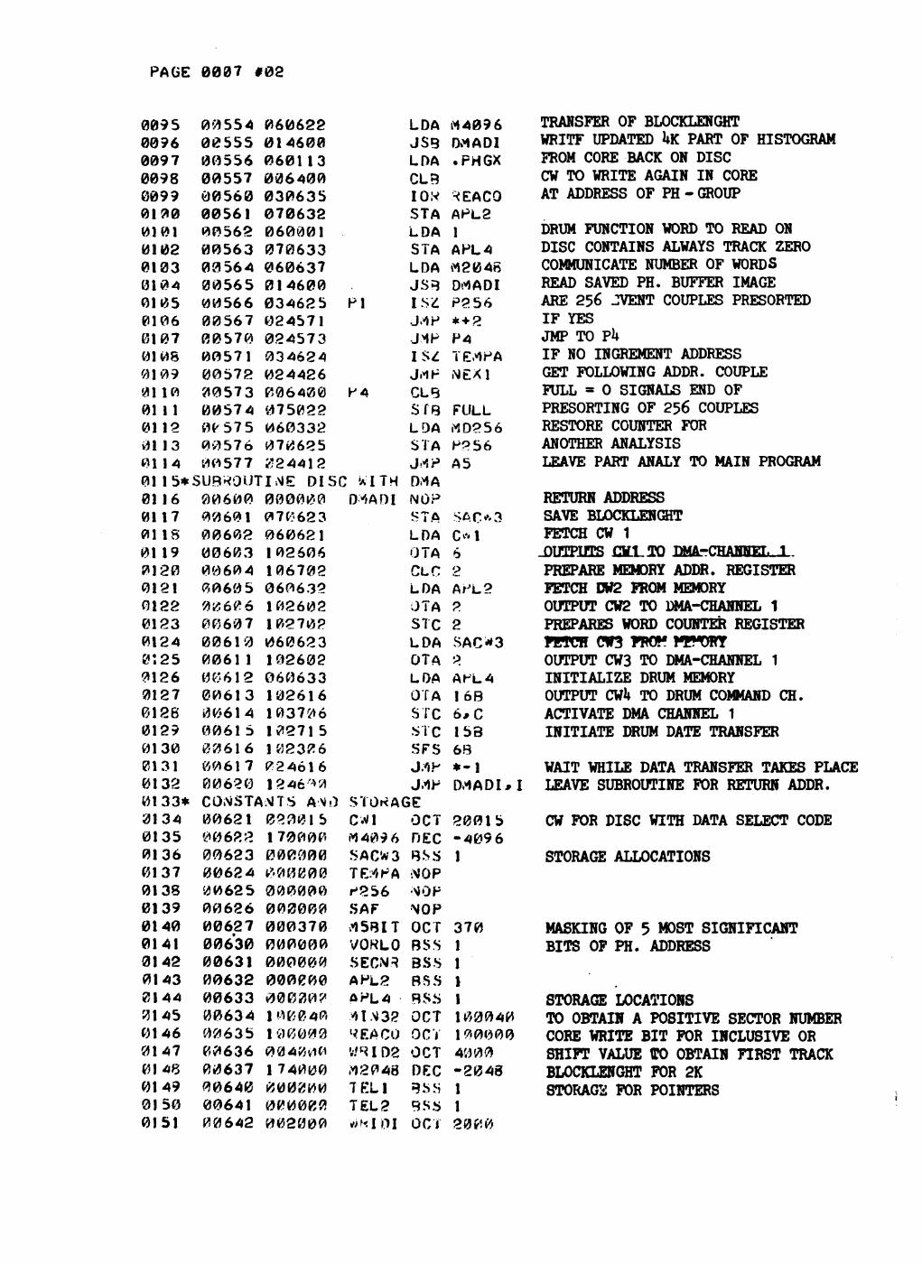
PAGE 0007 #02
009 5 0 0 9 6 0 0 9 7 0 0 9 8 0 0 9 9 0 1 0 0 0 1 0 1 0 1 0 2 0 1 0 3 0 1 0 4 0 1 0 5 0 1 0 6 0 1 0 7 0 1 0 8 0 1 0 9 01 10 01 1 1 0 1 1 2 01 13 01 14
0 0 5 5 4 0 0 5 5 5 0 0 5 5 6 0 0 5 5 7 0 0 5 6 0 0 0 5 6 1 0 0 5 6 2 0 0 5 6 3 0 3 5 6 4 0 0 5 6 5 0 0 5 6 6 0 0 5 6 7 0 0 5 7 0 0 0 5 7 1 0 0 5 7 2 0 0 5 7 3 0 0 5 7 4 0 C 5 7 5 0 0 57 6 0 0 5 7 7
0 6 0 6 2 2 0 1 4 6 0 0 0 6 0 1 1 3 0 0 6 4 0 0 0 3 0 6 3 5 0 7 0 6 3 2 0 6 0 0 0 1 0 7 0 6 3 3 0 6 0 6 3 7 0 1 4 6 0 0 0 3 4 6 2 5 0 2 4 5 7 1 0 2 4 5 7 3 0 3 4 6 2 4 0 2 4 4 2 6 0 0 6 4 0 0 0 7 5 0 2 2 0 6 0 3 3 2 0 7 0 6 2 5 Ü 2 4 4 1 2
'X.
P 4
0 1 1 5 * S U B R O U T I N E D I S C WITH 01 16 0 1 1 7 0 1 1 S 01 19 0 1 2 0 0 1 2 1 0 1 2 2 0 1 2 3 0 1 2 4 0 Ï 2 5 0 1 2 6 0 1 2 7 0 1 2 8 0 1 2 9 0 1 3 0 0 1 3 1 0 1 3 2 01 3 3 * 0 1 3 4 0 1 3 5 0 1 3 6 0 1 3 7 0 1 3 8 0 1 3 9 0 1 4 0 0 1 4 1 0 1 4 2 0 1 4 3 0 1 4 4 0 1 4 5 0 1 4 6 0 1 4 7 0 1 4 8 0 1 4 9 0 1 5 0 0 1 5 1
0 0 6 0 0 0 0 6 0 1 0 0 6 0 2 0 0 6 0 3 0 0 6 0 4 0 0 6 0 5 0 0 Ó 0 6 0 0 6 0 7 0 0 6 1 0 0 0 6 1 1 0 0 6 1 2 0 0 6 1 3 0 (4614 0 0 6 1 5 0 0 6 1 6 0 0 6 1 7 0 0 6 2 0
0 0 0 0 0 0 0 7 0 6 2 3 0 6 0 6 2 1 1 0 2 6 0 6 1 0 6 7 0 2 0 6 0 6 3 2 1 0 2 6 0 2 1 0 2 7 0 ? 0 6 0 6 2 3 1 0 2 6 0 2 0 6 0 6 3 3 1 0 2 6 1 6 1 0 3 7 ^ 6 1 0 2 7 1 5 1 0 2 3 0 6 P 2 4 Ó 1 6 12 4 6 * a
CONSTANTS A \ 0 0 0 6 2 1 0 0 6 2 2 0 0 6 2 3 0 0 6 2 4 0 0 6 2 5 0 0 6 2 6 0 0 6 2 7 0 0 6 3 0 0 0 6 3 1 0 0 6 3 2 0 0 6 3 3 0 0 6 3 4 0 0 6 3 5 0 0 6 3 6 0 0 6 3 7 0 0 6 4 0 0 0 6 4 1 0 0 6 4 2
0 2 0 0 1 5 1 7 0 0 0 0 0 0 0 0 0 0 # 0 0 0 0 0 0 0 0 0 0 0 0 0 0 0 0 0 0 0 0 3 7 0 0 0 0 0 0 0 0 0 0 0 0 0 0 0 0 0 0 0 0 0 0 0 0 ? 1 0 & 0 4 0 1VJ0000 0040V10 1 7 4 0 0 0 0 0 0 0 0 0 0 0 0 0 0 0 0 0 2 0 0 0
DViADI
LDA J SB LDA CLB IOK STA LDA STA LDA JSB ISC _MP JMP I S ^ JrtP CLB STB L 9 A STA jy»p DMA NOP STA LDA OTA CLC LDA JTA STC LDA OTA LDA OTA STC STC SFS J/»P J 1 F
S T O K A G E
CW1 « 4 0 9 6 SACW3 TEtfPA P 2 5 6 S A F rt5BlT VONLO SECN3 APL2 ÛPL4 *1.M3J? 7F.AC0 WSID8 M 2 0 4 8 TEL1 T E L 2 w K i m
OCT DEC BSS •MOP •^OP
NOP OCT BSS BSS B5.S BSS OCT OCT OCT DEC BSS BSS OCT
114096 DMADI .PHGX
*EACO APL2 l APL4 M 2 0 4 8 DrtADI P 2 5 6 * + 2 P4 T Erf PA NEXl
FULL MD256 P 2 5 6 A5
SAC* 3 C" 1 6 o APL2 2 2 S A C * 3 P A PL 4 16B 6 * C 15B 6 8 * - l Dr tADI *
2 0 0 1 5 - 4 0 9 6 1
3 7 0 1 1 1 1 1 0 0 0 4 0 1 9 0 0 0 0 4 0 0 0 - 2 0 4 8 1 1 2 0 0 0
TRANSFER OF BLOCKLENGHT WRITF UPDATED UK PART OF HISTOGRAM FROM CORE BACK ON DISC CW TO WRITE AGAIN IN CORE AT ADDRESS OF PH - GROUP
DRUM FUNCTION WORD TO READ ON DISC CONTAINS ALWAYS TRACK ZERO COMMUNICATE NUMBER OF WORDS READ SAVED PH. BUFFER IMAGE ARE 256 JVENT COUPLES PRESORTED IF YES JMP TO PU IF NO INCREMENT ADDRESS GET FOLLOWING ADDR. COUPLE FULL - 0 SIGNALS END OF PRESORTING OF 256 COUPLES RESTORE COUNTER FOR ANOTHER ANALYSIS LEAVE PART ANALY TO MAIN PROGRAM
RETURN ADDRESS SAVE BLOCKLENGHT FETCH CW 1 .OUTPUTS J3LLT0 DMA_-CHAMEL_L. PREPARE MEMORY ADDR. REGISTER FETCH DW2 FROM MEMORY OUTPUT CW2 TO DMA-CHANNEL 1 PREPARES WORD COUNTER REGISTER FETCH CW3 TOO!? MfWRY OUTPUT CW3 TO DMA-CHANNEL 1 INITIALIZE DRUM MEMORY OUTPUT CWU TO DRUM COMMAND CH. ACTIVATE DMA CHANNEL 1 INITIATE DRUM DATE TRANSFER
WAIT WHILE DATA TRANSFER TAKES PLACE LEAVE SUBROUTINE FOR RETURN ADDR.
CW FOR DISC WITH DATA SELECT CODE
STORAGE ALLOCATIONS
MASKING OF 5 MOST SIGNIFICANT BITS OF PH. ADDRESS
STORAGE LOCATIONS TO OBTAIN A POSITIVE SECTOR NUMBER CORE WRITE BIT FOR INCLUSIVE OR SHIFT VALUE tTO OBTAIN FIRST TRACK BLOCKLENGHT FOR 2K STORAGE FOR POINTERS
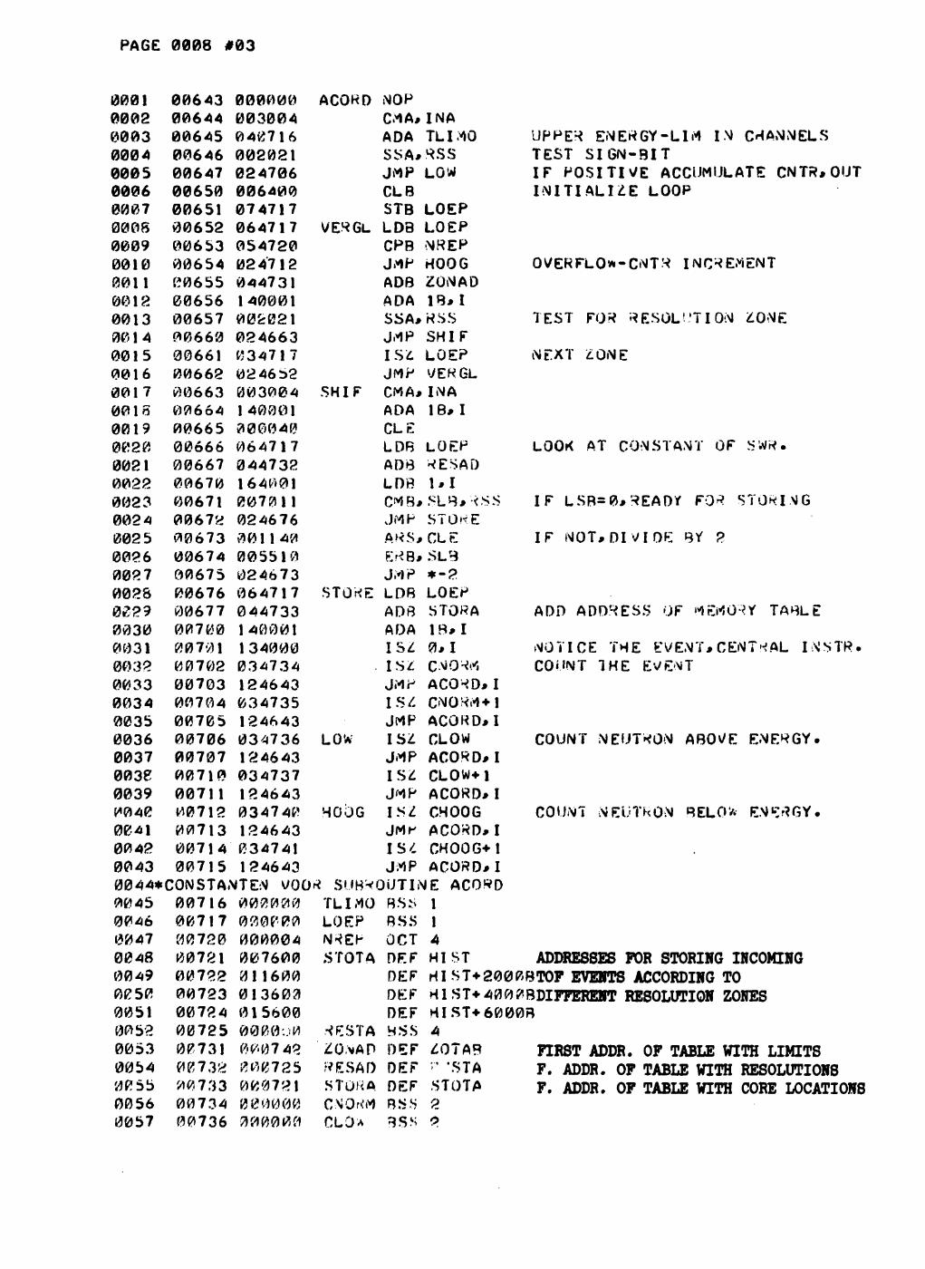
PAGE 0008 #03
0001 0002 0003 0004 0005 0006 0007 0008 0009 0010 0011 0018 0013 001 4 0015 0016 0017 00 IS 0019 0020 0021 0022 0023 0024 002 5 0026 0027 0023 0229 0030 0031 0032 0033 0034 0035 0036 0037 003P 0039 1*040 0041 0042 0043 0044* 0045 0046 0047 0048 0049 0050 0051 0052 0053 0054 00 55 0056 0057
00643 00644 00645 00646 00647 00650 00651 00652 00653 00654 00655 00656 00657 00660 00661 00662 00663 006Ó4 00665 00666 00667 00670 00671 00672 00673 00674 00675 00676 00677 00700 00701 00702 00703 00704 00705 00706 00707 00710 00711 00712 00713 00714 00715
000000 003004 040716 002021 024706 006400 074717 064717 054720 024712 044731 140001 002021 024663 034717 0246 52 003004 140001 000040 064717 044732 164001 007011 024676 001140 005510 024673 064717 044733 140001 134000 034734 124643 034735 124643 034736 124643 034737 124643 034740 124643 034741 124643
ACORD
VERGL
SHI F
NOP CMA*INA ADA TLIMÛ SSA*RSS JMP LOW CLB STB LOEP LDB LOEP CPB NREP JMP HOOG AOB ZONAD ADA IB*I SSA* RSS JMP SHI F I Sit LOEP JMP VERGL CM A* IN A ADA IB* I CLE LDB LOEP ADB RESAD LDB 1*1 CMB*SLB* RSS JMP STORE ArtS* CLE ERB*.SL3 J.'IP
STOKE
LOW
HOOG
LDB ADB ADA IS* IS* JMP IS/. JMP IS* JMP IS* JMP ISZ JMK IS* JMP
*-2 LOEP STOWA IB* I 0*1 CM O W ACOWD*I CNORM+1 ACORD* I CLOW ACORD*I CLOW+i ACORD*I CHOOG ACORD*I CHOOG*1 ACORD*I
CONSTANTEN VOO* SUBROUTINE ACORD 00716 000000 TLIMO BS.S l
LOEP NREP S TOT A
00717 00720 00721 00722 00723 00724 00725 00731 00732 00 733 00734 00736
030000 000004 007600 011600 013603 015600 0000o0 0007 42 000725 000721 000000 000000
••«ESTA ZON AD F* ESA f) STOK A CNORM CL O A
BSS OCT DE F DE F DEF DEF HSS DEF DEF DEF BS.S BSS
1 4 H IST
UPPER ENERGY-LIM I N CHANNELS TEST S I G N - B I T I F P O S I T I V E ACCUMULATE CNTR*OUT I N I T I A L I Z E LOOP
OVERFLOW-CNTR INCREMENT
TEST FOR RESOLUTION ZONE
NEXT ZONE
LOOK AT CONSTANT OF SWR.
I F L S B = 0 * R E A D ï FOR STORING
I F N O T * D I V I D E BY 2
ADD ADDRESS OF MEMORY TABLE
NOTICE THE EVENT*CENTRAL COUNT THE EVENT
I N S T R .
COUNT NEUTRON ABOVE ENERGY.
COUNT NEUTRON BELOW ENERGY.
ADDRESSES FOR STORING INCOMING HIST+2000BTOF EVENTS ACCORDING TO HIST* 4 0 0 0BDIFFEREHT RESOLUTION ZONES HIST+6000B 4 ZOTAB FIR8T ADDR. OF TABLE WITH LIMITS '*'•' 'STA F. ADDR. OF TABLE WITH RESOLUTIONS STOTA F. ADDR. OF TABLE WITH CORE LOCATIONS 2 o
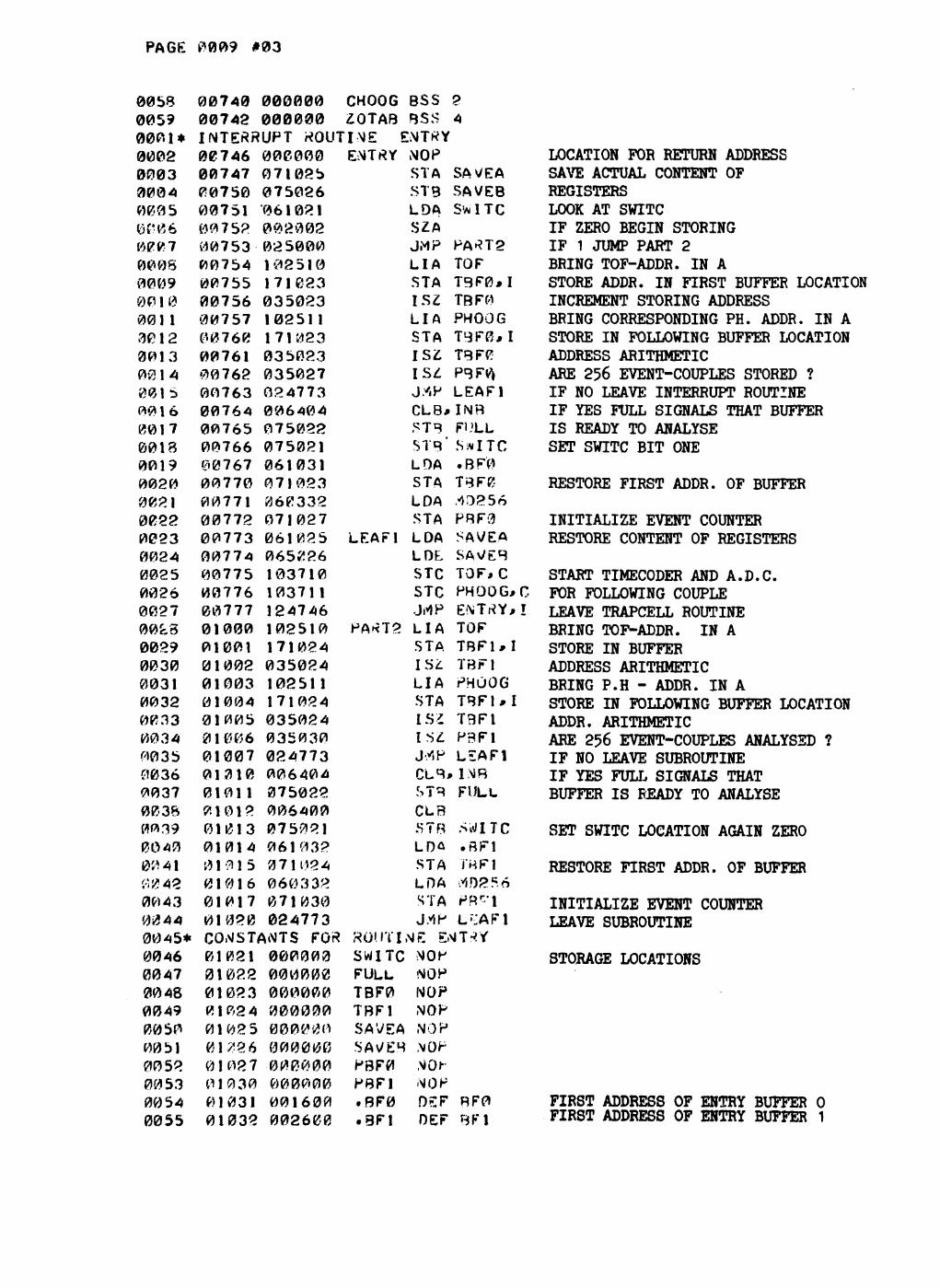
PAGE 0009 #03
0058 0059 0001* 0002 0003 0004 0(505
0007 0008 0009 0P1 0 001 1 3012 0013 0-314 0015 00 10 0017 0018 0019 0020 0021 0022 0023 0024 0025 0026 0027 00^5 0029 0030 0031 0032 0033 0034 0035 00 36 0037 00 38 0039 0040 00 41
0043 0044 0045* 0046 0047 0048 0049 0050 0051 0052 0053 0054
55
00740 000000 CHOOG BSS 2 00742 000000 ZOTAB BSS 4 INTERRUPT «OUTI ME EMTRY 00746 006000 00747 071025 00750 075026 00751 "061021 00 752 0 0 2 0 0 2 00753 025000 00754 102510 00755 171023 00756 035023 00757 102511 00760 171023 00761 035023 00762 035027 00763 02 4773 00764 006404 00765 075022 00766 075021 00767 061031 00770 071023 00771 «60332 00772 071027 00773 061025 00774 065226 00775 103710 00776 103711 00777 124746 01000 102510 01001 171024 01002 035024 01003 102511 01004 171024 01005 035024 01006 035030 01007 024773 01010 006404 01011 075022 01012 006400 01013 075021 0 1 0 1 4 0 6 1 0 3 2 017115 071D24 0 1 0 1 6 0 6 0 3 3 2 0 1 0 1 7 0 7 1 0 3 0 01020 024773 CONSTANTS FOR 01021 000000 01022 000000 01023 000000 01024 000000 01025 000000 01226 000000 01027 000000 01030 000000 01031 001600 01032 002600
ENTRY
LEAF1
P A K T 2
MOP STA STB LDA SZA JMP L I A STA ISZ L I A STA I S £ I S £ J/iP CLB, STB STB' LDA STA LDA STA LDA L O t STC STC JrtP L I A STA ÏSI L I A STA l HZ I S £ JY.P CLB
SA YEA SAVEB SWITC
PA*T2 TO F T 3 F 0 , I TBF0 PHOOG T 9 F 0 * I TBFP PBF0, LEAF1 1MB FULL
' S w I T C .BF0 TBFCJ .43256 PBF0 SAVEA SAv/EB TOF, C PHOOG#C ENTRY* ! TOF T B F 1 , I TBF1 PHÛOG TBFUI T 3 F I P3F1 LEAF1
* 1MB STB FULL CLB STB SWITC LDû .BF1 STA J"«F1 LDA mf>*6 STA P R r l J-MP L » : A F 1
ROUTINE &MTr?V SWITC »OP FULL NOP TBF0 NOP TBF1 NOP SAVEA NOP SA\/EB MOP PBF0 NOP PBF1 NOP .B F 0 DSF BF0 • 8 F I OEF BF1
LOCATION FOR RETURN ADDRESS SAVE ACTUAL CONTENT OF REGISTERS LOOK AT SWITC IF ZERO BEGIN STORING IF 1 JUMP PART 2 BRING TOF-ADDR. IN A STORE ADDR. IN FIRST BUFFER LOCATION INCREMENT STORING ADDRESS BRING CORRESPONDING PH. ADDR. IN A STORE IN FOLLOWING BUFFER LOCATION ADDRESS ARITHMETIC ARE 256 EVENT-COUPLES STORED ? IF NO LEAVE INTERRUPT ROUTINE IF YES FULL SIGNALS THAT BUFFER IS READY TO ANALYSE SET SWITC BIT ONE
RESTORE FIRST ADDR. OF BUFFER
INITIALIZE EVENT COUNTER RESTORE CONTENT OF REGISTERS
START TIMECODER AND A.D.C. FOR FOLLOWING COUPLE LEAVE TRAPCELL ROUTINE BRING TOF-ADDR. IN A STORE IN BUFFER ADDRESS ARITHMETIC BRING P.H - ADDR. IN A STORE IN FOLLOWING BUFFER LOCATION ADDR. ARITHMETIC ARE 256 EVENT-COUPLES ANALYSED ? IF NO LEAVE SUBROUTINE IF YES FULL SIGNALS THAT BUFFER IS READY TO ANALYSE
SET SWITC LOCATION AGAIN ZERO
RESTORE FIRST ADDR. OF BUFFER
INITIALIZE EVENT COUNTER LEAVE SUBROUTINE
STORAGE LOCATIONS
FIRST ADDRESS OF ENTRY BUFFER O FIRST ADDRESS OF ENTRY BUFFER 1
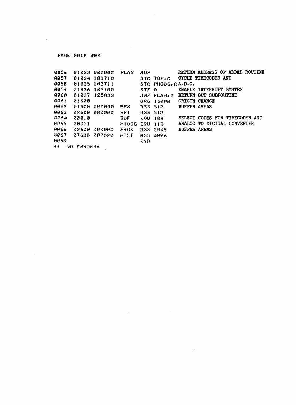
PAGE 0010 #04
0056 0057 0058 0059 0060 0061 0062 0063 OB 6 4 0065 #0óó 0067 0068 ** ,\*0
01033 01034 01035 01036 01037 01600 01600 02600 0 0 0 1 0 0001 1 0 3 6 0 0 0 7 6 0 0
0 0 0 0 0 0 1 0 3 7 1 0 1 0 3 7 1 1 1 0 2 1 0 0 1 2 5 0 3 3
0 0 0 0 0 0 0 0 0 0 0 0
0 0 0 0 0 0 0 0 0 0 0 0
FLAG
BF2 3F1 TOF PHOOG PHGX HIST
.\JOP STC 5TC STF JrtP OK G BSS BSS EOU EQU BSS BSS END
TOF,C PHOOG* 0 FLAG* I 1600B 512 512 10B 1 1 8 2 3 4 5 4 0 9 6
RETURN ADDRESS OF ADDED ROUTINE CYCLE TIMECODER AND
C A . D . C . ENABLE INTERRUPT SYSTEM RETURN OUT SUBROUTINE ORIGIN CHANGE BUFFER AREAS
SELECT CODES FOR TIMECODER AND ANALOG TO DIGITAL CONVERTER BUFFER AREAS
ErtRORS*