spring final review - home | university of colorado … april 2014 spring final review project...
TRANSCRIPT

Collision Encounter Reduction for Unmanned Aerial Systems (CERUNAS)
29 April 2014
Spring Final Review

Project Purpose and Objectives
Design Solution
Critical Project Elements
Design Requirements
Project Risks Verification and
Validation Project
Planning 2
Team Organization

Project Purpose and Objectives
Design Solution
Critical Project Elements
Design Requirements
Project Risks Verification and
Validation Project
Planning
Project Purpose and Objectives
Design Description
Test Overview
Test Results
Systems Engineering
Project Management
3
Overview

Project Purpose and Objectives
Design Solution
Critical Project Elements
Design Requirements
Project Risks Verification and
Validation Project
Planning 4
Project Purpose
and Objectives

Project Purpose and Objectives
Design Solution
Critical Project Elements
Design Requirements
Project Risks Verification and
Validation Project
Planning
Co
nc
ep
t o
f O
pe
ratio
ns
an
d
Critic
al P
roje
ct
Ele
me
nts
2 Nonfunctional CPEs: - CPE 4: sUAS Components < 100g - CPE 6: Subsystems < $100
CPE 5: Record Telemetry
CPE 2: Transmit
MAC Data
CPE 3: Initiate Avoidance
Full descriptions of CPEs can be found in Backup
Low Speed, Propeller Driven A/C (100m/s ± 10%) in straight, level flight in uncontrolled airspace
sUAS (< 2lbs, 10m/s ± 10%)
CPE 1: Determine Collision Potential
Purpose Design Test
Results 5 Test
Overview Systems
Project Mgmt.

Project Purpose and Objectives
Design Solution
Critical Project Elements
Design Requirements
Project Risks Verification and
Validation Project
Planning Purpose Design
Test Results
Test Overview
Systems Project Mgmt.
6
Project Levels of Success
(LOS)
LOS 1: Ability of System to sense
presence in MAEC
LOS 2: Ability of System to Trigger Removal of sUAS
from MAEC
LOS 3: Ability of System to
Sense Presence and Trigger Removal of sUAS from
MAEC
Manned A/C Encounter Cone (MAEC) is a geometric region based on the velocities of the sUAS and MAC

Project Purpose and Objectives
Design Solution
Critical Project Elements
Design Requirements
Project Risks Verification and
Validation Project
Planning 7
Design Description

Project Purpose and Objectives
Design Solution
Critical Project Elements
Design Requirements
Project Risks Verification and
Validation Project
Planning Purpose Design
Test Results
Test Overview
Systems Project Mgmt.
8
High Level HW Overview
Manned Aircraft Component sUAS Component
Mechanical components: • sUAS hardware enclosure Software: • sUAS code
Electrical Components: • Battery • sUAS PCB • Xbee receiver
CG
Mechanical Components: • Manned AC hardware
enclosure (6x6in, 1in deep)
Electrical Components: • Manned AC PCB • Xbee transmitter • GPS receiver • Battery Software: • Manned AC flight
software

Project Purpose and Objectives
Design Solution
Critical Project Elements
Design Requirements
Project Risks Verification and
Validation Project
Planning Purpose Design
Test Results
Test Overview
Systems Project Mgmt. 9
Pro
jec
t Fu
nc
tio
na
l Blo
ck
Dia
gra
m

Project Purpose and Objectives
Design Solution
Critical Project Elements
Design Requirements
Project Risks Verification and
Validation Project
Planning Purpose Design
Test Results
Test Overview
Systems Project Mgmt.
Ma
nn
ed
A/C
Ha
rdw
are
10
• PVC enclosure size: 5” x 6”

Project Purpose and Objectives
Design Solution
Critical Project Elements
Design Requirements
Project Risks Verification and
Validation Project
Planning Purpose Design
Test Results
Test Overview
Systems Project Mgmt. 11
Ma
nn
ed
A/C
Ele
ctr
on
ics
Layo
ut
HW Item Description Purpose Key Details
Power System Power all componentry on PCB – CERUNAS developed using COTS components
Voltage from battery: 7.4V Voltage after regulator: 5V Voltage to components: 3.3V
Processor and Supporting System
Main processor handling outgoing position data – Support systems for PIC are CERUNAS-developed using COTS components
ICSP Headers: flash program PIC Breakout Headers: general purpose I/O PIC comm. w/ XBee: 32 MHz (1 instr. cycle/4 clock cycles) LEDs: alive, GPS lock, transmission indicator
Location Verification System
Determine manned A/C position – COTS
GPS connects to PIC by asynch. serial at 9600 baud Pressure sensor: 24 bit conversion, absolute pressure
Communication System Broadcast location of manned A/C – COTS
XBee transmitter frequency: 900 MHz, 9600 bps XBee power draw: 260 mW at 3.3 V
Printed Circuit Board (PCB) Backplane for all necessary systems – CERUNAS developed
Size to fit componentry: 2” x 6”

Project Purpose and Objectives
Design Solution
Critical Project Elements
Design Requirements
Project Risks Verification and
Validation Project
Planning Purpose Design
Test Results
Test Overview
Systems Project Mgmt.
sUA
S H
ard
wa
re
12
• PCB cavity in DataHawk: 2” x 3”

Project Purpose and Objectives
Design Solution
Critical Project Elements
Design Requirements
Project Risks Verification and
Validation Project
Planning Purpose Design
Test Results
Test Overview
Systems Project Mgmt. 13
sUA
S E
lec
tro
nic
s La
yo
ut
HW Item Description
Purpose Key Details
Power System Power all componentry on PCB – CERUNAS developed using COTS components
Voltage from battery: 7.4V Voltage after regulator: 5V Voltage to components: 3.3V
Processor and Supporting System
Main processor for unpacking manned A/C position data and triggering avoidance – CERUNAS developed using COTS components
ICSP Headers: flash program PIC Breakout Headers: one pin triggers avoidance via autopilot PIC comm. w/ XBee: 9600 bps PIC comm. w/ autopilot: 57600 bps LEDs: alive (PIC OS running), power
Communication System
Receive location of manned A/C – COTS XBee transmitter frequency: 900 MHz, 9600 bps XBee power draw: 29 mW at 3.3 V
Printed Circuit Board (PCB)
Backplane for all necessary systems – CERUNAS developed
Size to fit componentry: 2” x 3”
Project Purpose and Objectives
Design Solution
Critical Project Elements
Design Requirements
Project Risks Verification and
Validation Project
Planning Purpose Design
Test Results
Test Overview
Systems Project Mgmt.
Ma
nn
ed
A/C
Flg
iht
So
ftw
are
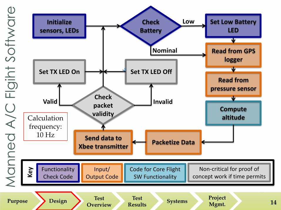
14
Check Battery
Initialize sensors, LEDs
Read from pressure sensor
Read from GPS logger
Compute altitude
Packetize Data Send data to
Xbee transmitter
Check packet validity
Set TX LED On Set TX LED Off
Set Low Battery LED
Invalid Valid
Low
Nominal
Ke
y:
Functionality Check Code
Input/ Output Code
Code for Core Flight SW Functionality
Non-critical for proof of concept work if time permits
Calculation frequency:
10 Hz
Project Purpose and Objectives
Design Solution
Critical Project Elements
Design Requirements
Project Risks Verification and
Validation Project
Planning Purpose Design
Test Results
Test Overview
Systems Project Mgmt.
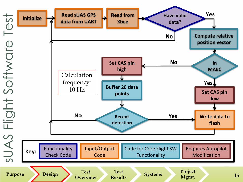
sUA
S F
ligh
t So
ftw
are
Te
st
15
Initialize Read sUAS GPS data from UART
Read from Xbee
Have valid data?
Compute relative position vector
In MAEC
Set CAS pin high
Set CAS pin low
Write data to flash
Recent detection
Buffer 20 data points
No
Yes
No
Yes No
Yes
Key: Functionality Check Code
Input/Output Code
Code for Core Flight SW Functionality
Requires Autopilot Modification
Calculation frequency:
10 Hz

Project Purpose and Objectives
Design Solution
Critical Project Elements
Design Requirements
Project Risks Verification and
Validation Project
Planning 16
Test Overview LOS 1 – Ground Test 1a
LOS 1 – Ground Test 1b
LOS 2 – Flight Test 2
LOS 3 – Flight Test 3

Project Purpose and Objectives
Design Solution
Critical Project Elements
Design Requirements
Project Risks Verification and
Validation Project
Planning Purpose Design
Test Results
Test Overview
Systems Project Mgmt.
CER
UN
AS T
est
Arc
hite
ctu
re
17
Electronics: individual component
Software
Subsystem
MAC component Validation
Hardware
sUAS component Validation
Populated PCB Validation
MAC enclosure
MAC mounting
sUAS component mounting
Level of Success 1 – Sensing Subsystem
Level of Success 2 – Avoidance Subsystem
HW Implementation &
Compliance
Level of Success 3 – Full System
Functionality
Factor of 1000 Reduction (SW
Model, Test Post-processing)
Integrated System
FAA Compliance
Ease of user Implementation
MAC, sUAS Unit Test
MAC, sUAS, Validation
Tests: 10 Reqts. Analyses: 17 Reqts. Inspections: 16 Reqts.
MAC, sUAS Subsystem Tests MAC/ sUAS mass &
C.G.

Project Purpose and Objectives
Design Solution
Critical Project Elements
Design Requirements
Project Risks Verification and
Validation Project
Planning Purpose Design
Test Results
Test Overview
Systems Project Mgmt. 18
Test 1a Goals: • Verify MAC Xbee can
transmit required beamwidth from MAC mock cockpit (CPE 2)
• Verify sUAS Xbee can receive MAC transmissions at 2km (CPE 1)
• Verify CERUNAS sensing at 2km decoupled from avoidance (CPE 1)
Required Output • MAC packet validity
indicators & heading • sUAS packet validity
indicators & GPS coordinates
• Physical measurements from range marking
Level of Success 1 – Sensing Subsystem Characterization, Range Test

Project Purpose and Objectives
Design Solution
Critical Project Elements
Design Requirements
Project Risks Verification and
Validation Project
Planning Purpose Design
Test Results
Test Overview
Systems Project Mgmt. 19
Required Output • Detection times • MAC packet validity,
coordinates, and heading • Pos/Neg MAEC
encounter indicators • Physical measurements
from range marking
Test 1b Goals: • Characterize accuracy of
CERUNAS sensing subsystem in relation to geometric MAEC (CPE 1)
• Verify that CERUNAS sensing system has capability to sense presence in MAEC decoupled from avoidance (CPE 1)
Level of Success 1 – Sensing Subsystem Characterization, MAEC Detection Test

Project Purpose and Objectives
Design Solution
Critical Project Elements
Design Requirements
Project Risks Verification and
Validation Project
Planning Purpose Design
Test Results
Test Overview
Systems Project Mgmt. 20
Test 2 Goals: • Verify CERUNAS
Avoidance capability decoupled from sensing capability (CPE 3)
• Verify that CERUNAS allows return to nominal flight after avoidance
• Characterize latency time required for switch-on of flight termination mode
• Characterize avoidance maneuver descent speed and expected duration
Required Output • FTM
initiation/termination indicators
• Latency time between FTM command and execution
• FTM initiation altitude
Level of Success 2 – Avoidance Subsystem Characterization
Project Purpose and Objectives
Design Solution
Critical Project Elements
Design Requirements
Project Risks Verification and
Validation Project
Planning Purpose Design
Test Results
Test Overview
Systems Project Mgmt. 21
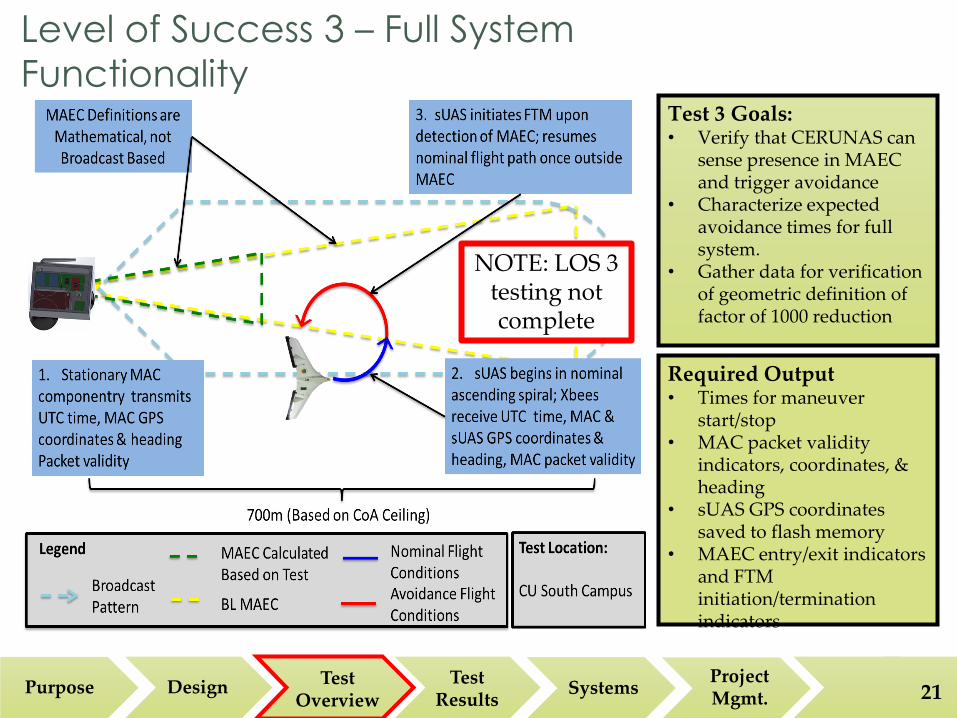
Test 3 Goals: • Verify that CERUNAS can
sense presence in MAEC and trigger avoidance
• Characterize expected avoidance times for full system.
• Gather data for verification of geometric definition of factor of 1000 reduction
Required Output • Times for maneuver
start/stop • MAC packet validity
indicators, coordinates, & heading
• sUAS GPS coordinates saved to flash memory
• MAEC entry/exit indicators and FTM initiation/termination indicators
Level of Success 3 – Full System
Functionality
NOTE: LOS 3 testing not complete

Project Purpose and Objectives
Design Solution
Critical Project Elements
Design Requirements
Project Risks Verification and
Validation Project
Planning 22
Test Results Modeling
LOS 1 – Ground Test 1
LOS 2 – Flight Test
Project Validation

Project Purpose and Objectives
Design Solution
Critical Project Elements
Design Requirements
Project Risks Verification and
Validation Project
Planning 23
Modeling - Monte Carlo Simulation
Comparison
Parameter Initial
Parameter Value Percent
Varied [%] Parameter Range
sUAS X Position 1000 m 21 790 – 1210 m
sUAS Y Position 2000 m 10 1800 – 2200 m
sUAS Z Position 10000 m 0.7 9930 – 10070 m
sUAS Lateral Speed 10 m/s 20 8 – 12 m/s
sUAS Vertical Speed (Operational Mode)
3 m/s 20 2.4 – 3.6 m/s
sUAS Vertical Speed (Flight Termination
Mode) 10 m/s 20 8 – 12 m/s
Latency to Initiate FTM 5 sec 90 0.5 – 9.5 sec
Latency to Exit FTM 5 sec 90 0.5 – 9.5 sec
Manned A/C Speed 100 m/s 20 80 – 120 m/s

Project Purpose and Objectives
Design Solution
Critical Project Elements
Design Requirements
Project Risks Verification and
Validation Project
Planning Purpose Design
Test Results
Test Overview
Systems Project Mgmt. 24
Modeling - Monte Carlo Simulation
Comparison
Collisions without CAS: 739/100,000 = 0.739%
Collisions with CAS: 653/100,000=0.653%
𝐹𝑎𝑐𝑡𝑜𝑟 𝑜𝑓 𝑅𝑒𝑑𝑢𝑐𝑡𝑖𝑜𝑛 𝐹𝑂𝑅 =# 𝐶𝑜𝑙𝑙𝑖𝑠𝑖𝑜𝑛𝑠 𝑤𝑖𝑡ℎ𝑜𝑢𝑡 𝐶𝐴𝑆
# 𝐶𝑜𝑙𝑙𝑖𝑠𝑖𝑜𝑛𝑠 𝑤𝑖𝑡ℎ 𝐶𝐴𝑆=
739
653= 1.13

Project Purpose and Objectives
Design Solution
Critical Project Elements
Design Requirements
Project Risks Verification and
Validation Project
Planning Purpose Design
Test Results
Test Overview
Systems Project Mgmt. 25
Modeling - Monte Carlo Simulation
Comparison

Project Purpose and Objectives
Design Solution
Critical Project Elements
Design Requirements
Project Risks Verification and
Validation Project
Planning Purpose Design
Test Results
Test Overview
Systems Project Mgmt. 26
Modeling - Monte Carlo Simulation
Comparison
Iteration MAEC Horizontal
Size [m] MAEC Vertical
Size [m]
Number of Collisions (out
of 100,000)
Factor of Reduction
1 200 66 (60+10%) 653 1.13
2 200 72 (60+20%) 505 1.46
3 200 78 (60+30%) 384 1.92
4 220 (200+10%) 78 (60+30%) 283 2.61
5 240 (200+20%) 78 (60+30%) 232 3.18
6 240 (200+20%) 84 (60+40%) 162 4.56
7 240 (200+20%) 90 (60+50%) 107 6.90
8 240 (200+20%) 96 (60+60%) 79 9.35
9 240 (200+20%) 102 (60+70%) 62 11.91
10 260 (200+30%) 102 (60+70%) 42 17.59
11 280 (200+40%) 102 (60+70%) 33 22.39
12 300 (200+50%) 108 (60+80%) 22 33.59
• MAEC horizontal and vertical size were increased to see impact on number of collisions (out of 100,000)

Project Purpose and Objectives
Design Solution
Critical Project Elements
Design Requirements
Project Risks Verification and
Validation Project
Planning Purpose Design
Test Results
Test Overview
Systems Project Mgmt. 27
Level of Success 1 – Sensing Subsystem Characterization, Range Test
Test Location: Manned A/C - NCAR sUAS - CU East Campus
Legend
Packets Received
Packets Not Received
Sensing Subsystem Characteristics: • Distance
Required – 2km Achieved – 4km
• Cross-sectional area:
Required – 120m x 415m Achieved – 256 x 300m
• Transmission along lateral
axis impeded by obstructions between South Campus testing site and NCAR

Project Purpose and Objectives
Design Solution
Critical Project Elements
Design Requirements
Project Risks Verification and
Validation Project
Planning Purpose Design
Test Results
Test Overview
Systems Project Mgmt. 28
Level of Success 2 – Flight Test 1 CONOPS
CAS light triggers red on ground
station
40 m
30 m
Launch James takes manual RC
control
Autopilot takes control Data Hawk begins helix flight
path
At 70 m, sUAS board triggers FTM
for 2 secs

Project Purpose and Objectives
Design Solution
Critical Project Elements
Design Requirements
Project Risks Verification and
Validation Project
Planning Purpose Design
Test Results
Test Overview
Systems Project Mgmt. 29
Level of Success 2 – Avoidance Subsystem Characterization

Project Purpose and Objectives
Design Solution
Critical Project Elements
Design Requirements
Project Risks Verification and
Validation Project
Planning Purpose Design
Test Results
Test Overview
Systems Project Mgmt. 30
Level of Success 2 – Avoidance Subsystem Characterization
Repetition FTM
Altitude (m) CAS
Verification Latency Time (s)
1 90 No -
2 70-75 Yes -
3 70-75 Yes -
4 70-75 Yes -
5 70-75 Yes -
6 70-75 No -
7 73 Yes 3.40
8 73 Yes 3.90
9 70 Yes 2.80
10 72 Yes 3.50
11 75 No -
12 70 Yes 2.10
13 71 Yes 2.20
14 71 Yes 2.70
15 70 Yes 4.10
16 70 No -
Avoidance Subsystem Characteristics: • CAS successful 12/16
trials
• FTM Switch-on Latency:
Expected – 2.00s Average – 3.08s
• FTM Initiation Altitude
Expected – 70.00m Average – 71.25m
• Variable in test code
times out after 4 repetitions, negating CAS, requires soft reset

Project Purpose and Objectives
Design Solution
Critical Project Elements
Design Requirements
Project Risks Verification and
Validation Project
Planning 31
Systems Engineering Approach
Engineering Issues
Key Lessons

Project Purpose and Objectives
Design Solution
Critical Project Elements
Design Requirements
Project Risks Verification and
Validation Project
Planning Purpose Design
Test Results
Test Overview
Systems Project Mgmt. 32
Systems Engineering Approach
Systems Engineer
Requirements verified and validated?
Structures Engineer
Develop requirements
Manufacturing Engineer
Design hardware components
Construct hardware
components
Electronics Engineer
Develop PCB architecture
SW and Modeling Engineer
Write code for interface between
mA/C and sUAS
Test Engineer
Design and perform tests for
requirements V&V
Project Completion
Key: Verification
and Validation Systems
Engineering Electronics & RF Equipment
Physical Componentry
Software and Modeling

Project Purpose and Objectives
Design Solution
Critical Project Elements
Design Requirements
Project Risks Verification and
Validation Project
Planning Purpose Design
Test Results
Test Overview
Systems Project Mgmt.
Connection between autopilot and CERUNAS
Code parsed data in different ways
Clock speed (57600 on autopilot) to change on CAS
Interfacing SPI between pressure sensor and mA/C PIC
33
Systems Engineering Issues
Components foregone in interest of time:
Interfacing between flash memory and PIC
*Given lower priority – have ground station telemetry
Second Xbee receiver for packet integrity
No time for battery power indicator
Original requirements not specific enough for full design outline
Project evolves in time with new information
Requirements rewritten as appropriate

Project Purpose and Objectives
Design Solution
Critical Project Elements
Design Requirements
Project Risks Verification and
Validation Project
Planning Purpose Design
Test Results
Test Overview
Systems Project Mgmt. 34
Key Lessons
Aspect of Project
Lesson
Requirement Development
- Keep project focused toward specific goals from customer, regulations, and mission success
- Requirements must evolve during entire process
System Interfaces
- Do not underestimate difficulty of tracking connections between individual components and subsystems
- Make sure to understand clocks, baud rates, transmission frequencies between existing technology and that developed for project
Verification and Validation
- Ensure tests track to established requirements, or else make changes to existing architecture
- “Verification means you built the right thing; validation means you built the thing right.”

Project Purpose and Objectives
Design Solution
Critical Project Elements
Design Requirements
Project Risks Verification and
Validation Project
Planning 35
Project Management Approach
Budget
Industry Cost Analysis

Project Purpose and Objectives
Design Solution
Critical Project Elements
Design Requirements
Project Risks Verification and
Validation Project
Planning
• Management via a systems level consideration of team activities • Activities monitored via inquiry, involvement, and
status meetings
• Scheduling based on understanding of development progress and team inputs regarding process • Adjusted based on progress and design changes • Personnel tasking based on skillsets and critical path
identification
• Ongoing documentation to ensure updated picture of system

Project Purpose and Objectives
Design Solution
Critical Project Elements
Design Requirements
Project Risks Verification and
Validation Project
Planning
Issue: Unexpected difficulty of integration with existing platform. Lesson: Account for additional time when integrating with existing systems
Issue: Critical path delays due to SW incompletion and personnel transition Lesson: Ensure that critical path tasking is allocated sufficient support at an early date
Issue: Insufficient time between completion of development and SWIT Lesson: Allocate additional buffer before test to allow for possibility of issues with SWIT

Project Purpose and Objectives
Design Solution
Critical Project Elements
Design Requirements
Project Risks Verification and
Validation Project
Planning Purpose Design
Test Results
Test Overview
Systems Project Mgmt. 38
Planned CDR Cost: $2242.63 Current Cost: $2434.51
Data Hawk HW borrowed from customer
PCB manufacture and remanufacture more
expensive than anticipated
Differences due to component
pricing

Project Purpose and Objectives
Design Solution
Critical Project Elements
Design Requirements
Project Risks Verification and
Validation Project
Planning Purpose Design
Test Results
Test Overview
Systems Project Mgmt. 39
$37,850 $39,517
$51,562
$28,977
$57,788
Estimated Total Project Cost: $215,690 Estimated Total Project Hours: 3450 • 24% SW • 27%
Electronics • 18% SEIT • 18% PM • 13% HW

Project Purpose and Objectives
Design Solution
Critical Project
Elements
Design Requireme
nts
Project Risks
Verification and
Validation
Project Plannin
g
Project Purpose and Objectives
Design Solution
Critical Project
Elements
Design Requireme
nts
Project Risks
Verification and
Validation
Project Plannin
g 40
Backup Charts

Project Purpose and Objectives
Design Solution
Critical Project
Elements
Design Requireme
nts
Project Risks
Verification and
Validation
Project Plannin
g
Project Purpose and Objectives
Design Solution
Critical Project
Elements
Design Requireme
nts
Project Risks
Verification and
Validation
Project Plannin
g Overview Schedule Manufacturing Status
Budget 41
Critical Project Elements CPE ID CPE Description Rationale
1
CERUNAS must determine that the sUAS is in the encounter cone of a manned A/C based on reception of a signal provided by the manned A/C
Indication of potential manned A/C-sUAS collisions
2
The manned A/C component of CERUNAS must be able to indicate either or both: The location and heading of the A/C Encounter cone boundaries for a sUAS
Indication of potential manned A/C-sUAS collisions
3 CERUNAS must initiate any sUAS maneuvers required to move the sUAS outside of the manned aircraft encounter cone
Avoidance of manned A/C-sUAS collisions
4 The sUAS elements of CERUNAS must have a mass of less than 100g
Weight key to effective integration of CERUNAS with existing sUAS components
5 Telemetry data for the sUAS must be collected and downlinked for any collision avoidance maneuvers
Need to understand CAS effectiveness in real-world flight and to validate mission success
6 CERUNAS transmitter and receiver units must each be mass producible for less than $100
- Cost-effective compared to cost of sUAS - Cost-effective for private pilot implementation

Project Purpose and Objectives
Design Solution
Critical Project Elements
Design Requirements
Project Risks Verification and
Validation Project
Planning
Se
nsi
ng
Te
st 1
A
Re
qu
ire
me
nts
42
Requirement Number Requirement Text
Syst
em
Lev
el
Re
qu
ire
men
ts
CAS.1
The CAS shall determine that the sUAS is in
the encounter cone of a manned A/C based on
reception of a signal provided by a manned
A/C in order to reduce the volume of the
MAEC by a factor of 1000.

Project Purpose and Objectives
Design Solution
Critical Project Elements
Design Requirements
Project Risks Verification and
Validation Project
Planning
Se
nsi
ng
Te
st 1
B
Re
qu
ire
me
nts
43
Requirement Number Requirement Test Sy
ste
m L
eve
l R
eq
uir
em
ents
CAS.1
The CAS shall determine that the sUAS is in
the encounter cone of a manned A/C based on
reception of a signal provided by a manned
A/C in order to reduce the volume of the
MAEC by a factor of 1000.
Fun
ctio
nal
Lev
el
Re
qu
ire
men
ts
CAS.1.1
The initial volume of the MAEC for the
manned A/C shall extend 2km in front of the
manned A/C at an angle defined by the
expected velocities for both the sUAS and
manned A/C.

Project Purpose and Objectives
Design Solution
Critical Project Elements
Design Requirements
Project Risks Verification and
Validation Project
Planning
Av
oid
an
ce
Te
st
Re
qu
ire
me
nts
44
Requirement Number Requirement Test
Syst
em
Lev
el
Re
qu
ire
men
ts
CAS.3
The CAS shall complete any sUAS maneuvers required to
move the sUAS outside of the MAEC while placing
primary focus on avoidance and secondary focus on
preservation of the sUAS.
Fun
ctio
nal
Lev
el R
eq
uir
em
ents
CAS.3.2.1 sUAS post-MAEC recovery shall return control of sUAS
flight operations to autopilot immediately after leaving
MAEC.
CAS.3.2.2 sUAS autopilot shall be allowed full control of sUAS
flight operations for remainder of mission following
avoidance.
CAS.3.2.3 Upon leaving MAEC, CERUNAS shall return control of
sUAS to the installed autopilot.
CAS.3.2.4 Recovery of sUAS shall return vehicle to original, pre-
encounter flight regime.
Project Purpose and Objectives
Design Solution
Critical Project Elements
Design Requirements
Project Risks Verification and
Validation Project
Planning
Fu
ll Fu
nc
tio
na
lity T
est
Re
qu
ire
me
nts
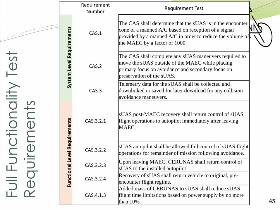
45
Requirement Number
Requirement Test
Syst
em
Lev
el R
eq
uir
em
en
ts
CAS.1
The CAS shall determine that the sUAS is in the encounter
cone of a manned A/C based on reception of a signal
provided by a manned A/C in order to reduce the volume of
the MAEC by a factor of 1000.
CAS.2
The CAS shall complete any sUAS maneuvers required to
move the sUAS outside of the MAEC while placing
primary focus on avoidance and secondary focus on
preservation of the sUAS.
CAS.3 Telemetry data for the sUAS shall be collected and
downlinked or saved for later download for any collision
avoidance maneuvers.
Fun
ctio
nal
Lev
el R
eq
uir
em
ents
CAS.3.2.1 sUAS post-MAEC recovery shall return control of sUAS
flight operations to autopilot immediately after leaving
MAEC.
CAS.3.2.2 sUAS autopilot shall be allowed full control of sUAS flight
operations for remainder of mission following avoidance.
CAS.3.2.3 Upon leaving MAEC, CERUNAS shall return control of
sUAS to the installed autopilot.
CAS.3.2.4 Recovery of sUAS shall return vehicle to original, pre-
encounter flight regime.
CAS.4.1.3 Added mass of CERUNAS to sUAS shall reduce sUAS
flight time limitations based on power supply by no more
than 10%.

Project Purpose and Objectives
Design Solution
Critical Project Elements
Design Requirements
Project Risks Verification and
Validation Project
Planning
Mis
ce
llan
eo
us
Test
Re
qu
ire
me
nts
46
Requirement Number Requirement Test
Pro
ject
Lev
el
Re
qu
ire
men
ts
CAS.5 Telemetry data for the sUAS shall be collected and
downlinked or saved for later download for any collision
avoidance maneuvers.
CAS.6
Testing shall be carried out to allow for characterization and
validation of CERUNAS system behaviors and to provide
discrete data for post-processing analysis of system
functionality. Fu
nct
ion
al L
eve
l Re
qu
ire
men
ts
CAS.2.2
The manned A/C mountable element of the CAS shall not
impact the functionality of any manned A/C HW or
communications systems and shall have the ability to comply
with applicable FAA regulations.
CAS.4.1 The sUAS elements of the CAS shall have a mass of less than
100g.
CAS.4.2 The sUAS elements of the CAS shall draw no more than 0.3
W from pre-existing UAV power.
CAS.2.1.1 Manned A/C mountable element of CAS shall have a
redundant system to ensure packet integrity.
CAS.2.2.4 Manned A/C mountable element power supply shall operate
as a single cell, with at least 5000 mAh and 3.3 V.
CAS.2.2.5 Manned A/C mountable element power supply shall be
rechargeable, with ~8 hr between charges.
CAS.2.3.1 Manned A/C component of CAS shall be functional without
impingement on pilot field of vision.

Project Purpose and Objectives
Design Solution
Critical Project Elements
Design Requirements
Project Risks Verification and
Validation Project
Planning
Mis
ce
llan
eo
us
Test
Re
qu
ire
me
nts
(c
on
t.)
47
Requirement Number Requirement Test
Fun
ctio
nal
Lev
el R
eq
uir
em
ents
CAS.2.5.1
Manned A/C component shall have the abliity to maintain
stationary functioning location in the manned A/C cockpit for
at least eight hours.
CAS.2.5.2 Manned A/C component of CAS shall be mounted via
industrial suction cups to A/C windshield.
CAS.4.1.1 Added mass to sUAS shall be distributed about center of mass
to maintain original mass distribution.
CAS.4.2.1 Power supply for sUAS mountable component of CAS shall
be rechargeable.
CAS.4.2.2 Power supply for sUAS mountable component of CAS shall
provide charge after a single charge cycle for a minimum of
30 minutes.
CAS.4.3.2 Technical installation of manned aircraft component should
require <5 minutes for full functionality.
CAS.4.3.3 LEDs shall be implemented into manned A/C component
circuitry to indicate power to component, sufficient battery
life, GPS lock, and packet integrity.
CAS.4.3.5 LEDs shall be implemented into sUAS mountable component
circuitry to indicate power to component and verify system is
on and software running.

Project Purpose and Objectives
Design Solution
Critical Project Elements
Design Requirements
Project Risks Verification and
Validation Project
Planning
Insp
ec
tio
n T
est
Re
qu
ire
me
nts
48
Requirement Number Requirement Test
Syst
em
Lev
el
Re
qu
ire
men
ts
CAS.2.4 Manned A/C CAS component printed circuit boards (PCBs)
shall be shielded from cockpit environmental factors
detrimental to electronics functioning.
CAS.2.5 Manned A/C component housing shall be detachable from any
stationary functioning location in the manned A/C cockpit. Fu
nct
ion
al L
eve
l Re
qu
ire
men
ts
CAS.1.1.1 Initial MAEC shall have a semi-minor half-angle of 1.71° and
a semi-major half angle of 5.71°, as defined by expected
manned A/C and sUAS velocities in a typical flight regime.
CAS.1.1.2
MAEC volume shall enclose the manned A/C such that the
cross-section of the cone will grow from an ellipse enclosing
the manned A/C dimensions to one that adds 60m to the minor
axis and 200m to the major.
CAS.2.1.1 Manned A/C mountable element of CAS shall have redundant
system to ensure packet integrity.
CAS.2.2.2 Manned A/C mountable element of CAS shall comply with 14
CFR §91.21 so as not to impinge upon the operation of the
existing navigation or communication systems.
CAS.2.2.3 Manned A/C mountable element of CAS shall be powered by
a designated power supply external to all A/C systems.

Project Purpose and Objectives
Design Solution
Critical Project Elements
Design Requirements
Project Risks Verification and
Validation Project
Planning
Insp
ec
tio
n T
est
Re
qu
ire
me
nts
(c
on
t.)
49
Requirement Number Requirement Test
Fun
ctio
nal
Lev
el R
eq
uir
em
ents
CAS.2.5.2 Manned A/C component of CAS shall be mounted via
industrial suction cups to A/C windshield.
CAS.4.3.3 LEDs shall be implemented into manned A/C component
circuitry to indicate power to component, sufficient battery
life, GPS lock, and packet integrity.
CAS.4.3.4 sUAS elements of CAS shall be secured within the sUAS
airframe.
CAS.4.3.6 LEDs shall be implemented into sUAS mountable component
circuitry to indicate power to component and verify system is
on and software running.
CAS.5.1.1 Telemetry data for collision avoidance maneuvers shall be
stored on sUAS onboard memory.
CAS.5.1.2 Telemetry system for CERUNAS avoidance maneuvers shall
be included in full sUAS component mass budget for test
vehicle.
CAS.5.1.3 Telemetry shall be stored in a format which allows for direct
download to a standard laptop or desktop computer.
CAS.6.1.1 Unit count to lower per unit price by mass production shall be
driven by conservative manufacturer price.
Project Purpose and Objectives
Design Solution
Critical Project Elements
Design Requirements
Project Risks Verification and
Validation Project
Planning
An
aly
sis
Test
Re
qu
ire
me
nts
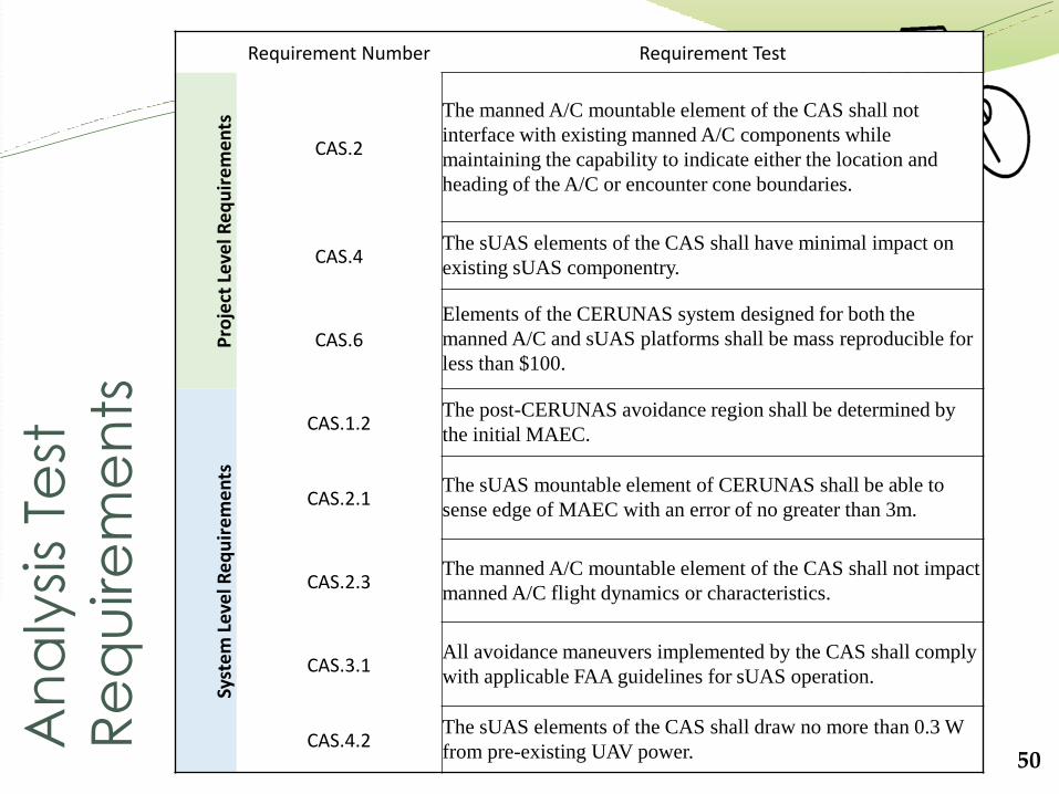
50
Requirement Number Requirement Test
Pro
ject
Lev
el R
eq
uir
em
ents
CAS.2
The manned A/C mountable element of the CAS shall not
interface with existing manned A/C components while
maintaining the capability to indicate either the location and
heading of the A/C or encounter cone boundaries.
CAS.4 The sUAS elements of the CAS shall have minimal impact on
existing sUAS componentry.
CAS.6 Elements of the CERUNAS system designed for both the
manned A/C and sUAS platforms shall be mass reproducible for
less than $100.
Syst
em
Lev
el R
eq
uir
em
en
ts
CAS.1.2 The post-CERUNAS avoidance region shall be determined by
the initial MAEC.
CAS.2.1 The sUAS mountable element of CERUNAS shall be able to
sense edge of MAEC with an error of no greater than 3m.
CAS.2.3 The manned A/C mountable element of the CAS shall not impact
manned A/C flight dynamics or characteristics.
CAS.3.1 All avoidance maneuvers implemented by the CAS shall comply
with applicable FAA guidelines for sUAS operation.
CAS.4.2 The sUAS elements of the CAS shall draw no more than 0.3 W
from pre-existing UAV power.

Project Purpose and Objectives
Design Solution
Critical Project Elements
Design Requirements
Project Risks Verification and
Validation Project
Planning
An
aly
sis
Test
Re
qu
ire
me
nts
(c
on
t.)
51
Requirement Number Requirement Test
Syst
em
Lev
el R
eq
uir
em
en
ts CAS.4.3
sUAS and manned A/C CAS component development shall
promote ease of implementation.
CAS.5.1 Telemetry data for any collision avoidance maneuvers shall be
saved on implemented sUAS internal data storage.
CAS.5.2
Telemetry data for any collision avoidance maneuvers shall be
uniquely recorded for a period beginning at the maneuver start
time and extending one (1) maneuver duration beyond the
maneuver end time.
CAS.5.3 The CAS elements for both the manned A/C and sUAS
platforms shall be demonstrably reproducible for $100 +/-
10% based on manufacturer input.
Fun
ctio
nal
Lev
el R
eq
uir
em
ents
CAS.2.2.1
Manned A/C mountable element of CAS shall comply with
Title 14 Code of Federal Regulations (14 CFR) §21.21,
§21.19, and §21.113 such that no re-certification of aircraft
type is required by installation of element.
CAS.3.2.2 Recovery of sUAS shall return vehicle to original, pre-
encounter flight regime within a 10% tolerance with respect to
pre-encounter sUAS velocity and maneuver
CAS.4.1.1 Added mass to sUAS shall be distributed about center of mass
to maintain the sUAS center of gravity.
CAS.4.1.2 The battery powering CERUNAS sUAS components shall
represent no more than 60% of the total CERUNAS mass
budget.
CAS.5.1.4 CAS telemetry system shall support sufficient memory to save
data for all avoidances maneuvers plus two (2) average
maneuver duration times.