spes project - unito.it · spes project selective production ... unknown shell-model interactions...
TRANSCRIPT

SPES Project
Selective Production of Exotic Species
Gianfranco Prete LNL-INFN On behalf of the SPES Collaboration
XXI GIORNATE DI STUDIO sui RIVELATORI Scuola F. Bonaudi Torino, 10 - 13 Maggio 2011 Centro Congressi di Villa Gualino

ISOL FACILITY
SPES layout SPES è un Progetto Speciale dell’INFN per la realizzazione di una facility di Fasci di ioni ricchi di neutroni. SPES è il progetto per lo sviluppo della Fisica Nucleare in Italia. Ha un costo valutato di 45 Milioni di euro. Il sito per la realizzaizone del progetto sono i Laboratori Nazionali di Legnaro.

1. Develop a Neutron Rich ISOL facility delivering Radioactive Ion Beams at 10AMeV using the LNL linear accelerator ALPI as re-accelerator .
2. Make use of a Direct ISOL Target based on UCx and able to reach 1013 Fission/s to produce neutron rich exotic beams.
1. Apply the technology and the components of the ISOL facility to develop
applications in neutron production and medicine.
a
b d
g
Exotic nuclei
ISOL facility for Neutron rich nuclei by
U fission 1013 f/s
high purity beam Reacceleration up to
>10 MeV/u
Applications
Proton and neutron facility for applied
physics
Radioisotope produduction
& Medical applications
SPES strategy

SPES Facility Layout
the SPES facility inside LNL
ALPI Exp. Hall 3
Spes isol
~ 50 x 60 m2
Second generation facility for the productin of radioactive beams coupled to the ALPI-LINAC accelerator

Vedremo
Perchè è interessante costruire una infrastruttura di ricerca
che acceleri fasci instabili
Come funziona la produzione di fasci instabili
Quali sono le parti principali del sistema Qual’è lo stato del progetto

Super Heavy stability ???
114
184
2 proton Radioactivity Prevista negli anni 60
94 Ag 2006 GSI
45 Fe 2000, Ganil
Halo nuclei Borromean nuclei 11Li Pigmy resonance
Evolution of shell nuclear structure
?
terra incognita
36 Si

The r-process
New element
(g,n) photodisintegration
Equilibrium favors
“waiting point”
b-decay
Neutron number
Seed
Rapid neutron
capture
neutron capture timescale: ~ 0.2 ms

Comportamento dei nuclei lontani dalla valle di stabilita’
Neutron Drip Line
Quanti neutroni si possono aggiungere ad un nucleo composto da Z protoni?
Perchè l’abbondanza di elementi nelle stelle non è quella che si trova sulla Terra?
Elemental solar abundance
Numeri magici e evoluzione del modello a shell
Nuove intereazioni tra i livelli nucleari possono far cambiare i Numeri Magici

Stable nuclei: N/Z ≈ 1 - 1.5, Sp ≈ Sn ≈ 6 - 8 MeV Homogeneously mixed protons and neutrons Good mean-field description Good “single-particle” picture (magic numbers) Large gaps between major shells Empirical shell-model interactions
Very neutron-rich nuclei: N/Z ≈ 2 - 2.5, Sn << 1 MeV Diffuseness of neutron distribution (neutron skins & halos)
More states near the Fermi surface Breakdown of the single-particle description Redefinition or disappearance of magic numbers Unknown shell-model interactions
protons neutrons
Qualitative Difference Near the Neutron-Dripline
ProtonNeutron
Neutron skin
r
Neutron halo
r
p/n decoupling
Stable Nucleus
r
Pygmy resonance
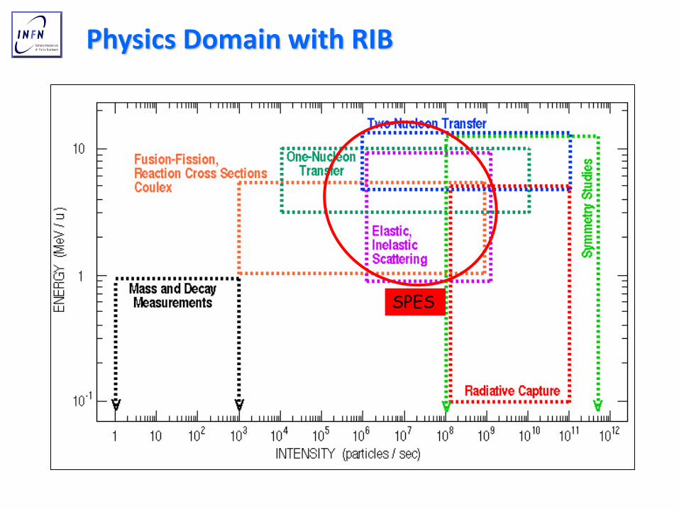
Physics Domain with RIB
SPES

Target 206 Pb
Beam 132Xe 144Xe
144Xe 132Xe
neutron-rich radioactive beams and transfer reactions: a tool to investigate nuclei far from stability
Coupled channel calculations (Grazing). G. Pollarolo

Calcolo dell’Energia di legame per nuclei sferici con Modello a Shell
Il Modello a Shell prevede un minimo a Z=114 N=184 Previsioni diverse sono fatte con calcoli Hatree-Fock e Relativistic Mean Field Reazioni con fasci instabili possono raggiungere questa regione.
Usando fasci esotici di Kr, Rb, Sr è possibile popolare Nuclei Composti ricchi di neutroni con Z =118-120-126. (96Kr,98Rb, 98Sr)
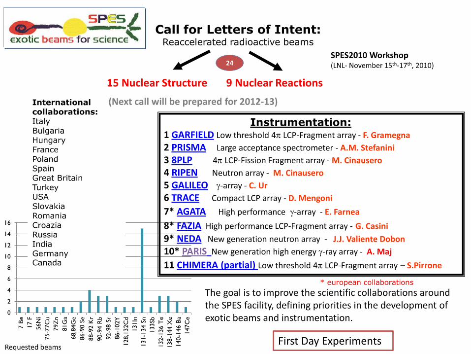
Call for Letters of Intent: Reaccelerated radioactive beams
15 Nuclear Structure 9 Nuclear Reactions
0
2
4
6
8
10
12
14
16
7 B
e
17 F
56N
i
75-7
7C
u
79Z
n
81G
a
68,8
4G
e
86-9
0 S
e
88-9
2 K
r
90-9
4 R
b
92-9
8 S
r
86-1
02Y
128,1
32C
d
131In
131-1
34 S
n
133Sb
132-1
36 T
e
138-1
44 X
e
140-1
46 B
a
147C
e
International collaborations: Italy Bulgaria Hungary France Poland Spain Great Britain Turkey USA Slovakia Romania Croazia Russia India Germany Canada
* european collaborations
First Day Experiments
SPES2010 Workshop (LNL- November 15th-17th, 2010)
The goal is to improve the scientific collaborations around the SPES facility, defining priorities in the development of exotic beams and instrumentation.
Requested beams
(Next call will be prepared for 2012-13)
Instrumentation: 1 GARFIELD Low threshold 4p LCP-Fragment array - F. Gramegna
2 PRISMA Large acceptance spectrometer - A.M. Stefanini
3 8PLP 4p LCP-Fission Fragment array - M. Cinausero
4 RIPEN Neutron array - M. Cinausero
5 GALILEO g-array - C. Ur
6 TRACE Compact LCP array - D. Mengoni
7* AGATA High performance g-array - E. Farnea
8* FAZIA High performance LCP-Fragment array - G. Casini
9* NEDA New generation neutron array - J.J. Valiente Dobon
10* PARIS New generation high energy g-ray array - A. Maj
11 CHIMERA (partial) Low threshold 4p LCP-Fragment array – S.Pirrone
24

Nuclear Physics European Coordination Committee
Radioactive Ion Beam production methods
Direct target
2 step target (n-induced reactions)

Nuclear Physics European Coordination Committee
European In Flight facility
European ISOL facility

5/30/2011
Alberto Andrighetto 2005
ISOL Possible configurations:
1 STEP:
Direct beam on target
2 STEP:Proton-Nuetron converter
Production Target
UCx
Beam
n, γ
Converter
UCx
Beam
Multi MW power 100KW power

ISOL Roadmap in EUROPE
2014-2025
FROM 2025
SPIRAL – LNS - EXCYT
TODAY 1012 fission/s , 2 MeV/n (A=130)
1013-14 fission/s 10 MeV/n (A=130)
> 1015 fission/s 100 MeV/n (A=130) 3x 100 kW direct target 1x 5 MW 2-step target

SPES - ISOL facility layout: Level -1
Cyclotron
ISOL bunker2
ISOL bunker1 Application
bunker2
Application
bunker1 RIB transport to
PIAVE-ALPI or
RFQ-pre accelerator
Artistic view of the SPES isol facility
High Resolution
Mass Spectrometer
Charge Breeder
Beam Cooler

Il progetto SPES produce fasci radioattivi utilizzando la tecnica ISOL con Bersaglio diretto
Cosa succede nel bersaglio: Reazioni nucleari e produzione di elementi esotici sezione d’urto Estrazione dei prodotti di reazione tempi di effusione-diffusione Potenza assorbita Perdita di energia fascio primario Potenza dissipata termica del sistema Bersaglio-sorgente
Caratteristiche e parametri fondamentali del bersaglio diretto
Fascio primario: PROTONI Ep > 40MeV Bersaglio: UCx
Obiettivi: raggiungere 1013 fissioni/s Minimizzare i problemi di radioprotezione

Gianfranco Prete 2006
Experimental Fission Cross Section of 238U -> Ref:
- Phys Rev 111(1958) 886;
- Nucl Phys A175(1971) 177;
- Nucle. Sci. Eng. 136 (2000) 340
Cross Sections
238U Fission Cross Section
0
0.5
1
1.5
2
2.5
3
0 5 10 15 20 25 30 35 40 45 50 55 60 65 70 75 80 85 90 95 100
Energy (MeV)
Cro
ss S
ection
(Bar
n)
neutron
proton
deuteron
Threshold energy

Alberto Andrighetto 2008
FISSION SPECTRA.
Mass Fission Spectra
1.00E+08
1.00E+09
1.00E+10
1.00E+11
1.00E+12
75 85 95 105 115 125 135 145 155
Mass
Yie
ld (
1/s)
Uranium
Primary beam
(p, d, n, ….)
Fission reaction
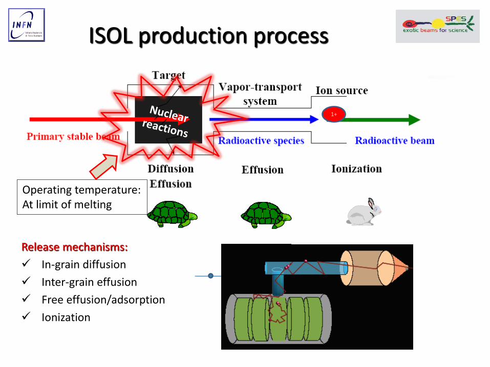
ISOL production process
Release mechanisms:
In-grain diffusion
Inter-grain effusion
Free effusion/adsorption
Ionization
Operating temperature: At limit of melting
1+

Geometry Entrance window
Exit hole
(0.4 cm inner radius)
Container : Cylindrical tube (1 mm thick): radius 4 cm; length 24 cm
7 UCx Disks: radius 3 cm, 1 mm thick. Mass ~9 g; ( = 2.5 g/cm3)
3 Graphite Disks: radius 3 cm, 0.2 mm thick. ( = 1.75 g/cm3)
Graphite window: radius 4 cm, 0.4 mm thick.
Spacing Between disks: 2 cm
Exit cone length: 12 cm
7 Ucx disks +
3 graphite disks

GEANT4 Example One event 132Sn generated in the the first UCx disk.
Number of bounces:3485
The events originate with the thermal velocity in the region of the UCx disks with a probability given by mcnpx calculations. The beam shape is supposed to be uniform on the disks surfaces
When an atom strike the walls of the container or the disks it is emitted following the cosine law after the “sticking time”
• 1000 events
• Average number of bounces: 4161 + 195
• Average mean path: 166 + 7 m
Ion (T1/2) Teffusion (s)
132Sn (39.7s) 0.25 + 0.01
EFFUSION time evaluation

Numbers of collisions and Release time
Collisions spes ALTO (Parnne)
With container 103 104 105
between grains 104 105 107
With pills 102 103 105
N = 105 N = 107
Teff 0.1 1
Teff = walking time in the container
TSticking Sn = 10-6 sec
Tdiff Sn= 1sec (ISOLDE UCx material) It depends on the element and grain size
Release time = t = Tdiff + Teff + N x TSticking
tSPES = 1 + 0.1 + 0.1 = 1.2
tParnne= 1 + 1 + 10 = 12
22 + 22 tablets 2mmx15mm dia each
10 cm
ALTO target
SPIRAL2 Target ~ 30 times ALTO
SPES target
7 UCx disks + 3 graphite 1mm x 40 mm dia each
20cm
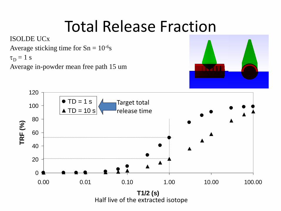
Total Release Fraction ISOLDE UCx
Average sticking time for Sn = 10-6s
tD = 1 s
Average in-powder mean free path 15 um
cono orizzontale
0
20
40
60
80
100
120
0.00 0.01 0.10 1.00 10.00 100.00
T1/2 (s)
TR
F (
%)
TD = 1 s
TD = 10 s
Half live of the extracted isotope
Target total release time

Effusion-diffusion effect on isotopes release
1-step: p 40 MeV 200mA on multi-slice direct target (30gr UCx)
Release times considered:
1-step 2 s proton induced fission
2-step 40 s neutron induced fission
Sn isotopes
1,00E+09
1,00E+10
1,00E+11
115 117 119 121 123 125 127 129 131 133 135 137
1-step
2-step
Sn isotopes
1,00E+05
1,00E+06
1,00E+07
1,00E+08
1,00E+09
110 115 120 125 130 135 140
1-step
2-step
data
In-target production from M.C.
Intensities evaluated considering
emission, ionization and acceleration
efficiencies
2-step: d 40 MeV 2mA on thick 12C converter + UCx target (800 gr) 1013 fissions/sec
N-rich N-rich “Data”Extrapolated from HRIBF

P = ε·σ · S· T4
Stefan-Boltzmann law
Stefan-Boltzmann Constant
Emissivity ε = 1 for black body, 0 for white body
Operando a 2000oC l’irraggiamento è il fenomeno principale di dissipazione della potenza perchè dipende dalla quarta potenza della temperatura.
Termica e dissipazione di potenza

Proton behaviour in the Target
Gianfranco Prete 2006
Stopping Power & Fission Cross Section for p-> UCx
0
0,5
1
1,5
2
2,5
3
3,5
4
4,5
2 6 10 14 18 22 26 30 34 38 42 46 50
Proton Energy (MeV)
Bar
n &
MeV
/dg*
cm2
.
Fission Cross Section
Stopping Power
For optimal configuration protons with high fission rate
are inside the Target, the rest inside the Dump
target Dump

40 MeV Multiple Target
Fission Fragments & Energy Loss in UC4
0
0.5
1
1.5
2
2.5
3
3.5
1 2 3 4 5 6 7
Target Number
MeV
& Y
ield
Energy Loss (MeV)
Fission (per 1000 proton)
Power distribution: Direct target 7 disks 4 cm f ~1 mm thick
Energy loss UCx (30gr) 23 MeV 4.2 KW
(600 W each disk, ~140 W/gr)
Window energy loss 200 W
beam-dump 3.5 KW
Fission efficiency
100p per 1.5 Fission Fragments
~ 200 mA 1013 fissions/sec
Beam power = 40 MeV p x 200 mA = 8 KW
Proton beam
Ion source

40 MeV Multiple Target : Temperature distribution in the disks (R=3cm)
Gianfranco Prete 2006
disk thickness
[mm]
power [W]
Tmax [°C]
DT-max radial dir.
[°C]
DT-max logitudinal
dir. [°C]
window 0.4 189 2069 22 0
target 1 1.4 583 2167 31 36
target 2 1.4 595 2175 50 38
target 3 1.4 606 2180 68 41
target 4 1.3 570 2176 78 39
target 5 1.3 580 2186 88 40
target 6 1.3 589 2195 98 44
target 7 1.2 560 2194 101 41
dump 1 0.8 539 2136 68 3
dump 2 0.7 583 2142 68 3
dump 3 1.0 595 2145 70 4
ENEA calculations benchmarked with ANSYS
UCx Melting point: 2350 oC
Container fixed at 2000oC (Pa)
Temperature distribution
Evaluated stress in
the disks
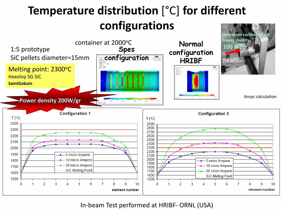
Temperature distribution [°C] for different configurations
Spes configuration
Normal configuration
HRIBF
1:5 prototype SiC pellets diameter=15mm
container at 2000oC
Melting point: 2300oC Hexoloy SG SiC SaintGobain
Ansys calculation Power density 200W/gr
Operation current 10 mA Power density
100 W/gr
In-beam Test performed at HRIBF- ORNL (USA)

Target technological Challanges Macro Micro
Target Yield
Design
1
MNMX
X
Y
Z
Target SPES
.797E+07
.291E+08
.502E+08
.714E+08
.925E+08
.114E+09
.135E+09
.156E+09
.177E+09
.198E+09
FEB 11 2007
23:44:17
NODAL SOLUTION
STEP=1
SUB =1
TIME=1
SEQV (AVG)
DMX =.571E-03
SMN =.797E+07
SMX =.198E+09
Electro-Thermo- Mechanical Calculations
Choice of Materials
Depending on: T,
Grain size (mm), Specific surface area (SSA, m2g-1),
Interconnectivity degree, Gas permeability (Pa*m-1)
UCx working at T= 2000 °C, p=10-5 mbar
Melting point, Vapour pressure Creep resistance
Thermal conductivity Emissivity
1013 f/s
Ytarget= Φ · σ · N · ε release · ε ionization · ε transport
21
)2ln(
Treleaset
erelease
=
trelease = tdiffusion + teffusion + Ncollisons·t sticking

SPES Pellets Production THE PELLETS PRODUCTION CONSISTS IN TWO PHASES: 1) GREEN PELLETS PRODUCTION (Oxide and Graphite Pellet ) 2) THERMAL TREATMENT
PRODUCTION OF OXIDE PELLET Mixing & Cold Pressing
THERMAL TREATMENT Up to 2000°C (several days)
Dip. di Chimica Universita’ di Padova: tesi di laurea sulla produzione di pellets in LaCx (2006)

Development of Porous Structures Macroporous LaCx Mesoporous LaCx
La2(C2O4)3+14C 2LaC2 + 7C+6CO(g) +3CO2(g) La2O3 + 11 C 2LaC2 + 4C + 3CO( g )
graphite and /or nanotubes
Porosity (pores size 5-10 mm) formation due to:
1. La2(C2O4)3 decomposition in La2O3
2. Carbothermal reduction of La2O3
L. Biasetto et al.,J. Nucl. Mat. 378 (2008) 180-187 L. Biasetto et al.,submitted to J. Nucl. Mat. Oct. (2008)
Porosity formation due to:
1. MWCNTs 45-50 nm 2. Carbothermal reduction of La2O3(pores size 5-10 mm)
Dip. Ing.dei Materiali Università di Padova

LaCx UCx
13 mm
40 mm
40
m
m
13 mm
TEST MATERIAL FINAL GOAL
Carbides production and characterization
LabView software controlling the heating/cooling schedule
Engineering the shielding system
Ultra High Temperature Furnaces
1) Carburization and sintering of carbides
2) Carburization and sintering of UCx
3) Off-line tests on materials (UHT behaviour)
4) Development of measurement systems i.e. thermal conductivity and emissivity
Carbide developments
20 40 60 80 100
0,0
0,2
0,4
0,6
0,8
1,0
§ * **
*
**** *
**
*
*
Inte
nsi
ty
2
*
* aUC2 pdf # 84-1344
§
§ Graphite pdf #
SEM Characterization
1000 1100 1200 1300 1400 1500 1600
0.0
0.2
0.4
0.6
0.8
1.0
UCx from UO
2+nC
em
iss
ivit
y
T (°C)
UCx emissivity
UCx
LaCx Similar challanges without radioactivity of UCx

Emissivity measurement method
1000 1200 1400 1600 1800 20000,0
0,1
0,2
0,3
0,4
0,5
0,6
0,7
0,8
0,9
1,0
SiCA (hexagonal, bulk)
SiCG (hexagonal, bulk)
SiC xycarb (cubic, porous)
Al2O3
Graphite (fine)
LaCx
T (°C)
Emissivity
Dual frequencies pyrometer
METHOD (published in EPJA ): - First the temperature is measured in bi-chromatic mode. - A the same T value, the pyrometer is switched in mono-cromatic mode. - The emissivity is tuned until the measured T in mono-chromatic mode matches the previous value.

Ionization Schemes - Induced by surfaces impact - Induced by photons - Induced by electron collisions
ION souces

Alberto Andrighetto 2008
Ion Sources efficiencies

Surface Ion source 1 2
H He 3 4 5 6 7 9 10
Li Be B C N O F Ne 11 12 13 14 15 16 17 18
Na Mg Al Si P S Cl Ar 19 20 21 22 23 24 25 26 27 28 29 30 31 32 33 34 35 36
K Ca Sc Ti V Cr Mn Fe Co Ni Cu Zn Ga Ge As Se Br Kr 37 38 39 40 41 42 43 44 45 46 47 48 49 50 51 52 53 54
Rb Sr Y Zr Nb Mo Tc Ru Rh Pd Ag Cd In Sn Sb Te I Xe 55 56 57 72 73 74 75 76 77 78 79 80 81 82 83 84 85 86
Cs Ba La Hf Ta W Re Os Ir Pt Au Hg Tl Pb Bi Po At Rn 87 88 89 104 105 106 107 108 109 110 111 112
Fr Ra Ac Rf Db Sg Bh Hs Mt
8
Elements with bad volatility (NOT EXTRACTED)
Surface Ionization Method (Alkaline)
Laser beam
Laser Ion source
Photo Ionization Method
Plasma Ionization Method (Halogen)
ION sources
Main fission 238U fragments febiad Ion source

Surface ionization Ion Source
3D FEM
0
400
800
1200
1600
2000
2400
2800
200 250 300 350 400 450 500
T [
°C]
I [A]
EXPERIMENTAL VS FEM Temperature measured at POINT 1
EXPERIMENTAL
I=3OO A
I=4OO A I=5OO A
I=4OO A
T1= 1997°C
T2= 1766°C

SPES ISOL Front end
TIS
60 kV insulator Steerer & Electric quads
Beam profile, Faraday cup & emittance-meter

Test of SPES UC2 targets (test performed on March ’10 at HRIBF)
• Seven UC2 samples prepared by the SPES Target Group
• Densities in the range of 4.2 g/cm3
• Used the SPES design for target geometry
• Heated to 2000° C for about two weeks without any out-gassing or obvious change in structure (samples observed after the on-line test)
M.Manzolaro, L.Biasetto, S.Corradetti, D.Scarpa, M.Lollo, A.Andrighetto, P.Zanonato (UniPD), D.Stracener (ORNL)

SPES Target Preliminary data of HRIBF experiment
Experiment March 2010 For expected beam on target, data are scaled to:
200 microA proton current
2-5% transport efficiency
Expected beam on target
A clean experiment needs to separate the ISOBARS produced

Beam selection and identification
Beam: Isobaric mixed Beam: A=82
Reaction: 2H(82Ge,p)83Ge Direct reaction in inverse kinematic
82Ge
82Ge
• Identification of beam and beam-like particles by Ionization Chamber, total rates up to 105 particles per second.
• A = 82 beam was composed of several isotopes: stable 82Se (85%), 82Ge (15%) and a trace of 82As (<1%).
• HRIBF: 5x10¹¹ f/s
First study of the level structure of the r-process nucleus 83Ge
ORNL-HRIBF J. S. Thomas et al. PHYSICAL REVIEW C 71, 021302 (2005)
81,929549725
81,916699401

48 Workshop LEA – SPES, 15-19 November 2010, LNL
What mass resolving power we need?
-50000
-40000
-30000
-20000
-10000
0
10000
20000
30000
40000
50000
10 20 30 40 50 60 70 80 Z
M/D
m
Cr, A=65
Ru, A=100
Ce, A=140
-550000
150000
-290000

HRMS physics design
1.3 mm
DM=2.5 10-5
3o order effects analysis Input parameters: Energy= 260 KeV D=4 mrad and DE= ± 1.3 eV Emittance=3p mm mrad Mass resolution: 1/40000 Expected after engineering design: 1/25000 (without RFQ cooler 1/8000)
A Scaled UP version of the separator
designed by Davids Cary at Argonne
• Bend=80° ρ=1.5 m, Bmax=1.2 T
• Energy 260 kV (1/132)
• (X,X’) emittance=2 p mmmrad
• (Y,Y’) emittance=4 p mmmrad
• Dipole Edge=28°
• Dm/M ~ 40.000
5.6
m
6.3 m
EQ1
EQ3
EQ2
Sx1 EQ1’
EQ2’
EQ3’
Sx2
Multipole
High resolution Mass Spectrometer is needed to separate beams of equal mass. The physics design of the spectrometer is completed.
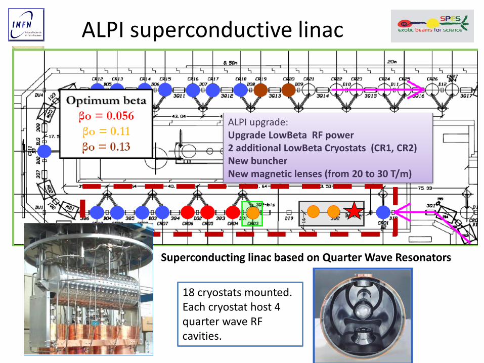
ALPI superconductive linac
18 cryostats mounted. Each cryostat host 4 quarter wave RF cavities.
Superconducting linac based on Quarter Wave Resonators
ALPI upgrade: Upgrade LowBeta RF power 2 additional LowBeta Cryostats (CR1, CR2) New buncher New magnetic lenses (from 20 to 30 T/m)

ALPI as post accelerator for SPES radioactive beams
•Up-grading program started in 1999: changing cavity sputtering from Pb on Cu to Nb on Cu or bulk Neobium. •2003 Up graded to Veq ~ 40 MV •2009: Up graded to Veq ~ 48MV •2010-2012: Low Beta RF upgraded to 5MV/m •Additional 2 Low Beta cryostats for SPES configuration
Expected Energies: beyond 10 MeV/A for beams with A~130
Expected SPES energies
Coulomb barrier on Pb
After linac upgrade
Actual linac
Linac upgrade & high energy stripper
30% efficiency

58
Cyclotron operation principle
Beam hits foil
Electrons are removed
H– becomes H+
Positive charge curves the other way
H+ ions (protons) leave the cyclotron
Easy to add multiple exit ports
By putting the foil at different points, protons are
extracted at any of a wide range of energies.
Vacuum chamber
RF (10-20 MHz, 10-100 kV)
H- acceleration and stripper foil extraction
Lawrence (idea 1929, Nobel price1939)
Forza centripeta= forza di Lorentz
f = const indipendente dal raggio dell’orbita

59
Compact cyclotron today
Fixed and variable energy negative ion cyclotrons for the production of commonly used PET (positron emission tomography) radioisotopes; F-18, N-13, O-15, C-11 and Pd-103, as well as research isotopes.

60
Proton energy variable in the range
35-70 MeV
•Minimum current outside the cyclotron
two extraction lines
700 μA (~ 4.2*1015 p/s)
Total power consumption 270kVA
Magnet: Diameter 4.5 m Height 2.3 m Weight 200 t Magnetic field 1.6 Tesla
SPES cyclotron Proton driver with the two distribution magnets for the two extraction lines

SPES collaborations network
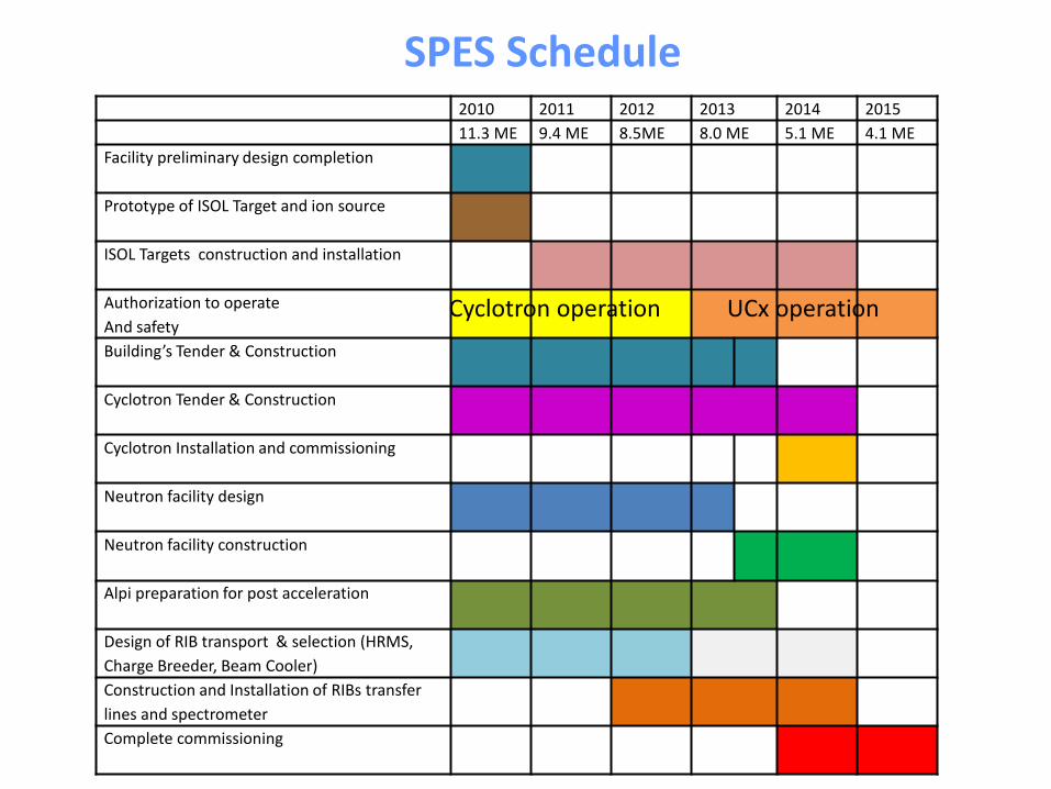
2010 2011 2012 2013 2014 2015
11.3 ME 9.4 ME 8.5ME 8.0 ME 5.1 ME 4.1 ME
Facility preliminary design completion
Prototype of ISOL Target and ion source
ISOL Targets construction and installation
Authorization to operate
And safety
Building’s Tender & Construction
Cyclotron Tender & Construction
Cyclotron Installation and commissioning
Neutron facility design
Neutron facility construction
Alpi preparation for post acceleration
Design of RIB transport & selection (HRMS,
Charge Breeder, Beam Cooler)
Construction and Installation of RIBs transfer
lines and spectrometer
Complete commissioning
SPES Schedule
Cyclotron operation UCx operation

CONCLUSIONI
Il Progetto SPES è stato approvato dall’INFN
Il bersaglio ISOL e la sorgente sono stati sviluppati e sono sotto test
E’ stato richiesta l’autorizzazione all’utilizzo della facility
Il contratto per la fornitura del ciclotrone è stato firmato a Novembre 2010
E’ stata assegnata la gara per la progettazione esecutiva dell’edilizia
Inizio lavori edilizia previsto per autunno 2012

Direct ISOL TARGET group
unit FTE task0 1 2 3 4 5 6 7 8 proj.leader
LNL 48 26,9 1,2 5,3 2,8 7,3 1,7 2,00 1,8 2,8 1,0 1,0
StaffLNL 31 14,2 0,7 3,0 0,8 2,3 1,7 0,7 0,5 2,5 1,0 1,0
total 67 35,4 1,4 5,3 3,3 11,9 2,9 2,5 2,3 3,3 1,5 1,0
PERSONNEL of project group
Grazie per l’attenzione !