spent fuel management of npps in argentina: conceptual design of the future atucha … · ·...
TRANSCRIPT

3rd International Seminar on Spent Fuel Storage
G. Moliterno, O. Beuter, J. M. Frediani, S. Zanni, J. P. Oyola
Oral presentation: P. Vizcaíno
Spent Fuel Management of NPPs in Argentina:Conceptual Design of the future Atucha I Dry Storage

2
Spent Fuel Management of
NPPs in Argentina
EMBALSE NPPPHWR - 648 MW
700 km from Buenos Aires
ATUCHA I NPPPHWR - 357 MW
112 km from Buenos Aires
PHWR - 692 MW112 km from Buenos Aires
ATUCHA II NPP under construction
Geographical localization

Embalse NPP
CNE reactor is a typical CANDU6 (648 MWe) on load PHWRthat is in operation in Argentinasince 1984.
Fuel bundles are composed by37 bars of 495.3 mm length.Each Zircaloy-4 bar contains 38UO2 pellets of natural uranium.Fuel assembly has an externaldiameter of 102.74 mm andcontains 22 Kg of UO2.

“Calandria” (right) has 380 horizontal pressuretubes /channels with a capacity of 4560 fuelbundles (12 per channel)Refueling at full power is 15.2 fuel bundles perday, maximum burn up 7800 MWd/tU
The spent fuel bundle are transferredunderwater to the reception bay(capacity: 4800 bundles).
They are disposed horizontally on trays of a double array of 12 bundles each onewhich are transferred to the storage bay and stocked in piles (capacity for 45144spent fuel bundles, that is, 10 full power years -FPY-).

A dry storage (right) was implemented in1993 to manage the spent fuel (SF) upto the end of life of CNE. SF bundlesremain at least 6 years in the pool andthen are transferred to the dry storage:concrete silos close to the CNE building.
Each full loaded silo (left) contains 9 steel sealedpiled baskets, each one with 60 bundles.They are 6.3 m high vertical cylinders and approx.3 m external diameter. Cooled by naturalconvection, were designed to support someaccidental events as earthquakes, floods, etc.,No especial activities of maintenance arenecessary when the silos are filled and sealed. Atpresent, there are 152 full loaded silos from 216.

The fuel assembly of ANPP I have anactive length of 5.3 [m] and a circularcross section of 0.10 [m] diameter, with36 fuel rods plus one structural rod.Each Fuel Assembly (FA) is loaded withapproximately 176 [kg] of UO2.
ANPP I was fuelled with natural uranium during the first 27 years of operation.The average burn up of the SF was approximately 6.000 [MWd/tU]. In Since 1995,the utility started a program to gradually convert the fuel to slightly enricheduranium (SEU) using an enrichment of 0.85% U-235.
Since august of 2001 the whole core is fuelled with SEU and the average burnup of the spent fuel element is approximately 11.300 [MWd/tU]. This changeproduced an important saving in fuel consumption: from 395 [FA/FPY] to 210[FA/FPY].
Atucha I is a PHWR (357 MWe) ofGerman origin which is in operationsince 1974.
Atucha I NPP

According to the scenario projected by NASA, considering a power factor of85% for ANPP I, the pool storage capacity will be exhausted in March 2015. PELby design will be reach in December 2017.
So, in order not to penalize plant operation, it is required to have at least 614free positions in the pool before March 2015.
To avoid interferences with the normal operation of the plant it was evaluated tomake the installation of a temporary Dry Storage Fuel Elements as an extension ofcontrolled area.
Prospective
The Fuel Elements (FE) Management Division of ANPP I determined that withthe proposed system (2016 FE storage capacity) the plant end of life (PEL) wouldbe exceeded in 5.27 FPY or 6.19 calendar years. (This is assuming a 0.72 FEdaily consumption, power factor of 85% and 250 reserves positions to emptythe reactor core). With this FE storage capacity the station could run untilFebruary 2024, if a Life Extension is got, time enough to build a Dry StorageSystem compatible with ANPP I and ANPP II.
Dry Storage Spent Fuel Element
Building
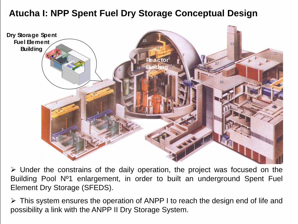
Atucha I: NPP Spent Fuel Dry Storage Conceptual Design
Under the constrains of the daily operation, the project was focused on theBuilding Pool Nº1 enlargement, in order to built an underground Spent FuelElement Dry Storage (SFEDS).
Reactor Building
This system ensures the operation of ANPP I to reach the design end of life andpossibility a link with the ANPP II Dry Storage System.

Fundamental Requirements to Dry Storage SystemSafe SFE confinement for a minimum of 50 years.
Subcriticality: The storage configuration must be subcritical.
Biological shield: The radiological limits should be respected.
Heat balance: The FE temperature should never exceed, inside the silo, themaximum allowable by the FE sheath.
System must be reversible, wet-dry-wet.
Passive cooling methods ensuring maximum temperature not to be exceeded.
Loading and unloading of the containers underwater.
The loaded transport shield must not exceed the capacity of the existentcrane.
Possibility to isolate both buildings.
To Include in the design the possible life extension of the ANPP I.
Must to be constructed and licensed by 2013 to allow sufficient time fortransfer SFE from pool I to SFEDS.
The conceptual design includes containment barriers which increase thesafety of the storage system.

Criticality of the configuration adoptedsystem criticality should be performed for different scenarios, both for normaloperation and accidental situations during storage maneuvers.
Calculation based on theregulations NUREG-1536¨Standard Review Plan for DryCask Storage Systems¨ andNUREG-1617 ¨Standard ReviewPlan for Transportation packagesfor spent nuclear fuel¨. Theseregulations establish criteria foracceptance a multiplication factorKeff ≤ 0.95.
View storage silos. Area for criticality calculations in red.

Wet storage: Pools in ANPP IThe average discharge rate with natural uranium for this burn up is of 1.4 SF/day,but the use of SEU reduced the discharge to 0.7 SF/day. The arising SF werestored in the original decaying water pools.Pool building 1, with two pools and Pool building 2, with four. The pools of the Poolbuilding 1 were completely filled in 1982, containing 3151 spent fuels (pool I: 1637,Pool II: 1514). This year the pool building 2 started to storage spent fuels and thisprocess continues up to the present.
Hanger loaded with fuels in the pool (upperlevel). Below the lower level (level 1)
Panoramic view of the four pools of thebuilding 2, the monitoring pool (down) andthe bridge. ANPP I.

Characteristics of the poolsThe dimensions of the pools are 5 m x 5 m x 17 m (deepness). These pools havetwo levels. The deeper level or level one is the first to be filled. For the building 1,both levels of the pools are fully occupied.The SF are vertically suspended from a hanger. The present hangers are amodification respect to the original design, changed in 1982, when the pools of thebuilding 2 began to operate. This improvement allowed to increase the pools storagecapacity.
There are two types ofhangers:Singles: capacity for168 SF.Doubles: capacity for280 SF.
Tool used to place or remove the fuels from the hangers.

Dry Storage: installation overview
As explained before, thenecessary time to transfer 1998SFE (a complete pool capacity)to the Dry Storage place will takeapproximately one year.
To avoid interferences with the plant normal operation, it is preferable to performthe Spent Fuel Elements Dry Storage in vertical silos in the Pool Building 1. TheSpent Fuel Elements (SFE) of that pool are stored there since the plant startoperation. The underground silos should be an extension of the existing buildingand with a load capacity of 1890 SFE (15 rows x 7 columns x 18 FE -2 basket of 9FE -). Dry Storage SFE
(Future Building)
Services Building
Pool Building
Nº 1
SFE Storage building layout
An additional line (7 x 18) for 126FE will be used to accommodatediscarded fuel (cooling) channels

Pool building I extension
Cooling equipment room
Building Pool I
Decaying pool
Maneuver pool
Bridge (to be extended)
Isolation gate
Maneuver bridge of building pool I
Loading port
Installation overview…

Shielding when is out of serviceSilos: 15 rows x 7 columns
containing two basket with 9 FE each one = 1890 FE
Row for storage of internal reactor components
Installation overview…

Steel silo roof
Reinforced concrete silo
wall
Silo floor elevation
Foundation slab
Silos Island
Water Compressed air Ventilation Electric power Radiation monitoring systems
Enlargement ofthe crane bridgerails
The new building should have the services of the present SFE Building to be able to carry out the correct transfer, maintenance and complete control of the system.
Silos BuildingThe installation provides for the enlargement of SFE Building I, towards the westside, a building which will contain two underground silos with 2016 SFE capacity,including internal components of the reactor, now deposited in SFE Building I and II(Cooling Channels, Control Rod Guide Tubes, Control Rods, etc).

SilosSilo’s capacity: two baskets with 9 SFE each, with stainless steel wall, dryingpiping and silo monitoring.Heat dissipation of SFE: using natural thermal convection inside the closed silo.Instrumentation: provided to allow getting information of the equilibrium temperatureand radiological status.
Silo without SFE
Silo with SFE
Sectional view of the support greed

Support grid
Protection Plate against impact and SFE spacing
Lifting tool coupling plate of the transport
container
Automatic positioning lock on which SFE hang
Storage Unit (Basket)The SFE will be stored in steel rectangular baskets, with 9 units capacity each.They have a support system on top which allows locking with the lifting tool.

Shielding for lifting and transportationTo remove the baskets with the SFE inside them, the facility has a structure with twofunctions: store the baskets inside them and provide adequate shielding level for theworkers.
Shielding for lifting and transportation

CoolingNatural convection internal coolingThe gas inside the silo (not defined yet) will flow from bottom to the top by naturalthermal convection, and will transmit the accumulated heat on top by conductionthrough the walls to the silo building.
Bottom and Top of the Silo. Gas circulation by means of natural convection.

Sectional view of silo unit. Air distribution among silos trough the airinjection duct at the bottom. Air extraction is trough the upper area.
External cooling by means of forced convection and conduction through thesilo wall.Silos cooling are made by forced convection air circulation through the ventilationsystem, which extracts the heat produced in the silo by conduction. The heat istransmitted by conduction through the concrete silo wall. The atmosphere betweensilos is under depression related to building environment.

Conclusions:Temporary Dry Storage in an enlargement of Pool Building I is shown as themost economical and simplest alternative from the licensing point of view asSFE are not removed from the controlled zone, allowing the operation of ANPP Iuntil the Dry Storage System for ANPP II is put into service. Construction details will be analyzed at the detail engineering stage, whichshould be done parallel to the licensing stage.With this system: SFE will not leave the Controlled Zone (which means, lower demands forlicensing) and allows additional containment barriers (Silo, Silo Structure andReinforced Concrete Wall of the Silo) which decrease potential radiological impacton the Environment. SFE can shift from wet storage to Dry Storage, and eventually go back to wetstorage, according to CNEA’s decision after discontinuing its operation in 2017.It allows to store irradiated internal components of the Reactor (Channels, ControlRod Guide Tubes), which now are taking place in the decay pools. Decrease investment regarding other proposed systems.It allows normal operation of ANPP I until reaching the end of its life according todesign and considers a possible life extension, enough to connect to the futureCNA II Dry Storage System.