speed control of separately excited dc motor using
TRANSCRIPT

SPEED CONTROL OF SEPARATELY EXCITED DC MOTOR USING
ARTIFICIAL INTELLIGENT APPROACH
ALBINUS BERNARD
A project report submitted in partial
fulfillment of the requirement for the award of the
Master of Electrical Engineering
Faculty of Electrical and Electronic Engineering
Universiti Tun Hussein Onn Malaysia
JANUARY 2013

ABSTRACT
This paper presents the ability of Artificial Intelligent Neural Network ANNs for the
separately excited dc motor drives. The mathematical model of the motor and neural
network algorithm is derived. The controller consists two parts which is designed to
estimate of motor speed and the other is which to generate a control signal for a
converter. The separately excited dc motor has some advantages compare to the
others type of motors and there are some special qualities that have in ANNs and
because of that, ANNs can be trained to display the nonlinear relationship that the
conventional tools could not implemented such as proportional-integral-differential
(PID) controller. A neural network controller with learning technique based on back
propagation algorithm is developed. These two neural are training by Levenberg-
Marquardt. The effectiveness of the proposed method is verified by develop
simulation model in MATLAB-Simulink program. The simulation results are
presented to demonstrate the effectiveness and the proposed of this neural network
controller produce significant improvement control performance and advantages of
the control system DC motor with ANNs in comparison to the conventional
controller without using ANNs.

ABSTRAK
Kertas kerja ini membentangkan tentang keupayaan Artificial Intellengent dalam
penggunaan jaringan saraf tiruan ANNs bagi tujuan memacu motor AT teruja asing.
Model untuk matematik bagi motor dan algoritma untuk jaringan saraf tiruan ANNs
telah diterbitkan. Pengawal terdiri daripada dua bahagian yang direka bentuk untuk
menganggarkan kelajuan motor dan yang sebahagian lagi menjana isyarat kawalan
untuk penukar. Motor AT teruja asing mempunyai beberapa kelebihan berbanding
dengan jenis motor yang lain serta terdapat beberapa sifat istimewa yang ada dalam
ANNs dan kerana itu, ANNs boleh dilatih untuk memaparkan hubungan ciri-ciri tidak
linear dengan alat konvensional yang mana tidak dapat dilaksanakan seperti
pembezaan penting berkadar (PID) pengawal. Pengawal jaringan saraf dengan teknik
pembelajaran dalam talian berdasarkan algoritma penyebaran belakang dibangunkan.
Kedua-dua neural adalah dilatih dengan Levenberg-Marquardt. Keberkesanan
kaedah yang disaran ini terbukti dengan membangunkan model simulasi dalam
program MATLAB-Simulink. Keputusan simulasi dipaparkan bagi menunjukkan
keberkesanan bahawa pengawal jaringan saraf pembelajaran yang dicadangkan itu
menghasilkan peningkatan prestasi kawalan yang sejajar serta kelebihan yang ada
pada sistem kawalan motor AT dengan menggunakan ANNs dibandingkan dengan
pengawal konvensional tanpa menggunakan ANNs.

vii
CONTENTS
TITLE i
DECLARATION ii
DEDICATION iii
ACKNOWLEDGEMENT iv
ABSTRACT v
CONTENTS vii
LIST OF TABLES x
LIST OF FIGURES xi
LIST OF SYMBOLS AND ABBREVIATIONS xiii
CHAPTER 1 INTRODUCTION 1
1.1 Project Background 1
1.2 Problem Statement 2
1.3 Project Objectives 3
1.4 Project Scopes 3

viii
CHAPTER 2 LITERATURE REVIEW 4
2.1 DC Motor 4
2.1.1 Advantages of DC Motor 4
2.1.2 Disadvantages of DC motor 5
2.1.3 Classification of DC Motor 5
2.2 Separately excited DC motor 6
2.2.1 Operation 6
2.2.2 Speed Control Techniques In Separately Excited
DC Motor 6
2.2.3 Field And Armature Equations 7
2.2.4 Basic Torque Equation 7
2.2.5 Steady State Operation 8
2.2.6 Steady State Torque And Speed 8
2.2.7 Torque And Speed Control 9
2.2.8 Variable Speed Operation 9
2.2.9 Base Speed And Field Weakening 10
2.3 Neural Network 10
2.3.1 What Is A Neural Network 11
2.3.2 Artificial Neural Networks 11
2.3.3 Neuron Model 13
2.3.3.1 Transfer Functions 14
2.3.4 Historical Background 16
2.3.5 Why Use neural Networks 16
2.3.6 Neural Networks Versus Conventional Computer 17
2.3.7 Estimating The Speed Using Neural Networks 18
2.3.8 Description Of Previous Methods 19
CHAPTER 3 METHODOLOGY 21
3.1 Introduction 21
3.2 Mathematics Modelling 21
3.2.1 The conventional control system of DC motor 23
3.2.2 The control system of DC motor using ANNs 23
3.2.3 The structure and the process of learning ANNs 24
3.3 NN Predictive Control 27
ix
3.3.1 System Identification 27
3.3.2 Predictive Control 28
3.3.3 Back propagation algorithm 29
3.3.4 Learning with Back Propagation Algorithm 30
3.3.5 Implement of back propagation algorithm 32
3.4 Flow Chart 33
CHAPTER 4 RESULT AND ANALYSIS 35
4.1 Data Analysis 35
4.2 Design and Modelling Works 36
CHAPTER 5 CONCLUSIONS AND FUTURE WORK 43
5.1 Conclusions 43
5.2 Design and Modelling Works 44
REFERENCES 45
APPENDICES 47
x
LIST OF TABLES
2.1 Previous research in DC motor using different type
of controller 20
4.1 The Results of the ANNs training 35
4.2 Parameter of conventional of separately excited DC motor 37

xi
LIST OF FIGURES
2.1 Equivalent circuit of separately excited DC motor 6
2.2 Separately excited DC motor in steady state 8
2.3 Torque vs speed characteristic for different armature voltages 9
2.4 Torque vs speed and power vs speed characteristic of separately
excited DC motor 10
2.5 Natural neurons (artist’s conception) 12
2.6 An artificial neuron 12
2.7 Neuron model 13
2.8 Hard-limit transfer function 14
2.9 Linear transfer function 15
2.10 Log-sigmoid transfer function 15
2.11 The structure of the neural network 18
2.12 Block diagram of a two hidden layer multiplayer perceptron(MLP) 19
3.1 The block diagram of a variable speed neural network Separately
Excited DC motor drive system 21
3.2 The mathematical model of a separately DC motor 22
3.3 Conventional model of control system DC motor 23
3.4 DC motor control model with ANNs 24
3.5 Structure of ANN1 25
3.6 Structure of ANN2 25
3.7 The Reference speed DC motor 26
3.8 The target speed DC motor 27
3.9 The process model predictive control 28
3.10 The structure of the neural network plant model 28
3.11 The controller block model predictive control process 29
3.12 Back Propagation Network 31

xii
3.13 Process involved during the project 33
3.14 The flow cart of separately excited DC motor simulation model 34
4.1 Blocks diagram of the proposed ANNs conventional for
Separately DC motor without ANNs controller 36
4.2 Blocks diagram of the proposed ANNs for
separately DC motor with ANNs controller 36
4.3 Starting the DC motor – conventional model
without ANNs controller 37
4.4 Starting the DC motor – model with ANNs controller 38
4.5 Regulating of DC motor speed– conventional model
without ANNs controller 38
4.6 Regulating of DC motor speed– model with ANNs controller 38
4.7 Regulating of DC motor speed– conventional model
without ANNs controller 39
4.8 Regulating of DC motor speed– model with ANNs controller 39
4.9 Starting the DC motor. 40
4.10 Starting the DC motor. 40
4.11 Starting the DC motor. 41
4.12 Neural network training tool (nntraintool) 41
4.13 Plot performance of neural network training tool 42
4.14 Plot training state of neural network training tool 42
4.15 Plot regression of neural network training tool 42

xiii
LIST OF SYMBOLS AND ABBREVIATIONS
ANNs - Artificial Neural Networks
- Field Current
- Instantaneous Field Current
- Instantaneous Armature Current
- The Motor Back EMF
- Torque Develop by Motor
- Rotor Speed (rad/sec)
- Terminal Voltage (V)
- Armature Current (A)
- Load Torque (Nm)
J - Rotor Inertia (N )
KF - Torque & Back EMF Constant (N )
- Viscous Friction Coefficient (Nms)
- Armature and Field Resistance, (Ω)
- Armature and Field Inductance, (H)
- Time Mechanical
MLP - Multilayer Perceptron
DC - Direct Current
SISO - Single Input Single Output
BP - Back Propagation
PID - Proportional Integral Derivative
CHAPTER 1
INTRODUCTION
1.1 Project Background
The development of high performance motor drives is very important in industrial
applications. Generally, a high performance motor drive system must have good
dynamic speed command tracking and load regulating response. The new
technologies are emerging for control scheme. In recent two decades, soft
computation is used widely. They are;
1) Artificial Neural Network (ANN)
2) Fuzzy Logic Set (FLS)
3) Fuzzy-Neural Network (FNN)
4) Genetic Algorithm Based System (GAB)
5) Genetic Algorithm Assisted System (GAA)
Neural network and fuzzy logic technique are quite different, and yet with
unique capabilities useful in information processing by specifying mathematical
relationships among numerous variables in complex system, performing mappings,
control of nonlinear system to a degree not possible with conventional linear
systems. Artificial Neural Networks (ANNs) is based on the operating principle of
human nerve neural. This method is applied to control the motor speed [1]. For this
project Neural Network technique, in speed control is used for a separately excited
DC motor. The rotor speed of dc motor can be made to follow an arbitrary selected

2
trajectory. The purpose is to achieve accurate trajectory control of the speed
especially when the motor and load parameters are unknown.
1.2 Problem Statements
DC motor is still the most common choice if wide range of adjustable speed drive
operation is specified. Among the three types of DC motors, such as series, shunt and
separately excited DC motors. The separately excited DC motors are most often
used. Different speed can be obtained by changing the armature voltage and the field
voltage. The significant feature of separately excited DC motor configuration is its
ability to produce high starting torque at low operation speed [2]. Although the
conventional cascade PID technique [3] is widely used in DC motor speed and
position control, it isn’t suitable for high performance cases, because of the low
robustness of PID controller. Many researchers have been studying various new
control techniques in order to improve the system performance [4-5].
This project proposed a new ability of artificial neural networks (ANNs) in
estimating speed and controlling the separately excited dc motor to achieve the over
speed self-regulating. The neural estimator used to estimate the motor speed and the
neural controller is use to generate a control signal for a converter. From the
simulation result are present to demonstrate the effectiveness of this neural and
advantage of the control system DC motor with ANNs in comparison with the
conventional scheme without ANNs. ANNs Controller is chosen to interface with the
DC motor because in ANNs, Non-adaptive control systems have fixed parameters
that are used to control a system. These types of controllers have proven to be very
successful in controlling linear, or almost linear, systems.

3
1.3 Project Objectives
The major objective of this project is it must estimating and control the speed of DC
motor with Artificial Neural Network controller using MATLAB application which
the design of the ANNs controller is provided and can be tune. Each of the
experimental result must be compared to the result of simulation, as a way to attain
the closely approximation value that can be achieved in this system.
Its measurable objectives are as follows:
a) To identify the separately excited dc motor model for control speed condition.
b) To determine the performance based on the ANNs simulation.
1.4 Project Scopes
This project is primarily concerned with the control of the DC motor speed. The
scopes of this project are:
a) To investigate ANNs controller which are used to estimating and control
technique in simulation?
b) DC motor control model with ANNs and structure ANNs.
c) The performance analyses of the motor.

1
CHAPTER 2
LITERATURE REVIEW
2.1 DC Motor
The dc motors are used in various applications such as defence, industries, Robotics
etc. The preferences are because of their simplicity, ease of application, reliability
and favourable cost have long been a backbone of industrial applications. DC drives
are less complex with a single power conversion from AC to DC. DC drives are
normally less expensive for most horsepower ratings. DC motors have a long
tradition used as adjustable speed machines and a wide range of options have
evolved for this purpose. In these applications, the motor should be precisely
controlled to give the desired performance. Many varieties of control schemes such
as P, proportional integral (PI), proportional derivation integral (PID), adaptive,
fuzzy logic controller (FLCs) and Artificial Neural Networks (ANNs) have been
developed for speed control of dc motors.
2.1.1 Advantages of DC motor:
Ease of control
Deliver high starting torque
Near-linear performance

5
2.1.2 Disadvantages of DC motor:
High maintenance
Large and expensive (compared to induction motor)
Not suitable for high-speed operation due to commutator and brushes
Not suitable in explosive or very clean environment
2.1.3 Classification of DC Motor:
Separately exited DC motor
Self-exited DC motor these are further classified into several types,
DC shunt motor
DC series motor
Brushless DC motor
Compound motors

6
2.2. Separately excited DC motor
Figure 2.1 shows the equivalent circuit of separately excited DC motor.
Figure 2.1: Equivalent circuit of separately excited DC motor
The field windings are used to excite the field flux. Armature current is
supplied to the rotor via brush and commutator for the mechanical work. Interaction
of field flux and armature current in the rotor produces torque.
2.2.1 Operation
i) When a separately excited motor is excited by a field current of and
an armature current of flows in the circuit, the motor develops a
back emf and a torque to balance the load torque at a particular speed.
ii) The is independent of the . Each windings are supplied
separately. Any change in the armature current has no effect on the
field current.
iii) The is normally much less than the .
2.2.2 Speed control techniques in separately excited dc motor:
i) Varying the armature voltage in the constant torque region.
ii) In the constant power region, field flux should be reduced to achieve
speed above the rated speed.

7
2.2.3 Field And Armature Equations:
Instantaneous field current:
(2.1)
Where and are the field resistance and inductor, respectively.
Instantaneous armature current:
(2.2)
Where and are the armature resistance and induction, respectively.
The motor back emf, which is also known as speed voltage, is expressed as:
(2.3)
is the motor voltage constant (in V/A-rad/s) and is the motor speed (in rad/sec)
2.2.4 Basic Torque Equation:
For normal operation, the developed torque must be equal to the load torque plus the
friction and inertia,i.e.:
(2.4)
The torque developed by the motor is:
(2.5)
Where ( ) is torque constant in V/A-rad/sec.
Sometimes it is written as:
(2.6)
For normal operation, the developed torque must be equal to the load torque
plus the friction and inertia, i.e.:
Where
B: viscous friction constant, (N.m/rad/s)
: load torque (N.m)
J: inertia of the motor ( )

8
2.2.5 Steady state operation:
Under steady state operation, the time derivative is zero, assuming the motor is not
saturated. Figure 2.2 shows a separately excited DC motor in steady state.
Figure 2.2: Separately excited DC motor in steady state
For the field circuit,
(2.7)
The back emf is given by:
(2.8)
The armature circuit,
(2.9)
2.2.6 Steady state torque and speed:
The motor speed can be easily derived:
If is a small value (which is usual), or when the motor is lightly loaded;
i.e. is small, that is if the field current is kept constant, the motor speed depends
only on the supply voltage.
The developed torque is:
(2.10)
The required power is:
(2.11)

9
2.2.7 Torque and speed control:
From the derivation, several important facts can be deduced for steady state
operation of DC motor. For a fixed field current, or flux ( , the torque demand can
be satisfied by varying the armature current ( ).
The motor speed can be varied by:
Controlling (voltage control)
Controlling (field control)
These observations lead to the application of variable DC voltage for controlling the
speed and torque of DC motor.
2.2.8 Variable speed operation:
A family of steady state torque speed curves for a range of armature voltage can be
drawn as figure 2.3.
The speed of DC motor can simply be set by applying the correct voltage.
Note that speed variation from no-load to full load (rated) can be quite small. It
depends on the armature resistance.
Figure 2.3: Torque vs speed characteristic for different armature voltages

10
2.2.9 Base speed and field weakening
Figure 2.4 show, torque vs speed and power vs speed characteristic of separately
excited DC motor.
Figure 2.4: Torque vs speed and power vs speed characteristic of separately excited
DC motor
Base speed ( ): the speed which corresponds to the rated , rated and rated
Constant torque region (> ): and are maintained constant to met torque
demand. is varied to control the speed. Power increased with speed.
Constant power region (> ): is maintained at the rated value and is
reduced to increase speed. However, the power developed by the motor (=torque *
speed) remain constant. This phenomenon is known as field weakening.
2.3 Neural Network
Neural networks are wonderful tools, which permit the development of quantitative
expressions without compromising the known complexity of the problem. This
makes them ideal in circumstances where simplification of the problem, in order to
make it mathematically tractable and would lead to an unacceptable loss of
information. As pointed out by Ziman, there is a fine balance between over-
idealizing the initial hypothesis in order to make it amenable to mathematical
analysis, and abandoning reality [6].

11
2.3.1 What is a Neural Network
A neural network is a powerful data modelling tool that is able to capture and
represent complex input/output relationships. The motivation for the development of
neural network technology stemmed from the desire to develop an artificial system
that could perform intelligent tasks similar to those performed by the human brain.
Neural networks resemble the human brain in the following two ways:
i) A neural network acquires knowledge through learning.
ii) A neural network's knowledge is stored within inter-neuron
connection strengths known as synaptic weights.
An Artificial Neural Network (ANN) is an information processing paradigm
that is inspired by the way biological nervous systems, such as the brain, processing
the information. The key element of this paradigm is the novel structure of the
information processing system. It is composed of a large number of highly
interconnected processing elements (neurones) working in unison to solve specific
problems. ANNs like people, learnt by example. An ANN is configured for a specific
application, such as pattern recognition or data classification through a learning
process. Learning in biological systems involves adjustments to the synaptic
connections that exist between the neurones. This is true of ANNs as well.
The true power and advantage of neural networks lies in their ability to
represent both linear and non-linear relationships and in their ability to learn these
relationships directly from the data being modelled. Traditional linear models are
simply inadequate when it comes to modelling data that contains non-linear
characteristics.
2.3.2 Artificial Neural Networks
One type of network sees the nodes as ‘artificial neurons’. These are called artificial
neural networks (ANNs). An artificial neuron is a computational model inspired in
the natural neurons. Natural neurons receive signals through synapses located on the
dendrites or membrane of the neuron. When the signals received are strong enough

12
(surpass a certain threshold), the neuron is activated and emits a signal though the
axon. This signal might be sent to another synapse, and might activate other neurons.
Figure 2.5: Natural neurons (artist’s conception)
The complexity of real neurons is highly abstracted when modelling artificial
neurons. These basically consist of inputs (like synapses), which are multiplied by
weights (strength of the respective signals), and then computed by a mathematical
function which determines the activation of the neuron. Another function (which
may be the identity) computes the output of the artificial neuron(sometimes in
dependence of a certain threshold). ANNs combine artificial neurons in order to
process information.
Figure 2.6: An Artificial Neuron
The higher a weight of an artificial neuron is, the stronger the input which is
multiplied by it will be. Weights can also be negative, so we can say that the signal is
inhibited by the negative weight. Depending on the weights, the computation of the

13
neuron will be different. By adjusting the weights of an artificial neuron we can
obtain the output we want for specific inputs. But when we have an ANN of
hundreds or thousands of neurons, it would be quite complicated to find by hand all
the necessary weights. But we can find algorithms which can adjust the weights of
the ANN in order to obtain the desired output from the network. This process of
adjusting the weights is called learning or training.
The number of types of ANNs and their uses is very high. Since the first
neural model by McCulloch and Pitts (1943) there have been developed hundreds of
different models considered as ANNs. The differences in them might be the
functions, the accepted values, the topology, the learning algorithms, etc. Also there
are many hybrid models where each neuron has more properties than the ones we are
reviewing here.
Because of matters of space, we will present only an ANN which learns using
the back propagation algorithm (Rumelhart and McClelland, 1986) for learning the
appropriate weights, since it is one of the most common models used in ANNs, and
many others are based on it. Since the function of ANNs is to process information,
they are used mainly in fields related with it. There are a wide variety of ANNs that
are used to model real neural networks, and study behaviour and control in animals
and machines, but also there are ANNs which are used for engineering purposes,
such as pattern recognition, forecasting, and data compression.
2.3.3 Neuron Model
A neuron with a single scalar input and no bias appears on the left below.
Figure 2.7: Neuron Model

14
The scalar input p is transmitted through a connection that multiplies its
strength by the scalar weight w, to form the product wp, again a scalar. Here the
weighted input wp is the only argument of the transfer function f, which produces the
scalar output a. The neuron on the right has a scalar bias, b. You may view the bias
as simply being added to the product wp as shown by the summing junction or as
shifting the function f to the left by an amount b. The bias is much like a weight,
except that it has a constant input of 1.
The transfer function net input n, again a scalar, is the sum of the weighted
input wp and the bias b. This sum is the argument of the transfer function f. Here f is
a transfer function, typically a step function or a sigmoid function, which takes the
argument n and produces the output a.
2.3.3.1 Transfer Functions
Many transfer functions are included in this toolbox Matlab. Three of the
most commonly used functions are shown on Figure 2.8, 2.9 and 2.10.
Figure 2.8: Hard-Limit Transfer Function
The hard-limit transfer function shown above limits the output of the neuron
to either 0, if the net input argument n is less than 0; or 1, if n is greater than or equal
to 0. We will use this function in Chapter 3 “Perceptrons” to create neurons that
make classification decisions. The toolbox has a function, hardlim, to realize the
mathematical hard-limit transfer function shown on Figure 2.8.

15
The linear transfer function is shown in Figure 2.9 below.
Figure 2.9: Linear Transfer Function
The sigmoid transfer function shown on Figure 2.10 takes the input, which
may have any value between plus and minus infinity, and squashes the output into
the range 0 to 1.
Figure 2.10: Log-Sigmoid Transfer Function
This transfer function is commonly used in back propagation networks,
in part because it is differentiable. The symbol in the square to the right of each
transfer function graph shown above represents the associated transfer function.
These icons will replace the general f in the boxes of network diagrams to show the
particular transfer function being used.

16
2.3.4 Historical Background
Neural network simulations appear to be a recent development. However, this field
was established before the advent of computers, and has survived at least one major
setback and several eras. Many important advances have been boosted by the use of
inexpensive computer emulations. Following an initial period of enthusiasm, the
field survived a period of frustration and disrepute. During this period when funding
and professional support was minimal, important advances were made by relatively
few researchers.
These pioneers were able to develop convincing technology which surpassed
the limitations identified by Minsky and Papert. Minsky and Papert, published a
book (in 1969) in which they summed up a general feeling of frustration (against
neural networks) among researchers, and was thus accepted by most without further
analysis [7]. Currently, the neural network field enjoys a resurgence of interest and a
corresponding increase in funding.
2.3.5 Why use neural networks
Neural networks with their remarkable ability to derive meaning from complicated or
imprecise data can be used to extract patterns and detect trends that are too complex
to be noticed by either humans or other computer techniques. A trained neural
network can be thought of as an expert in the category of information it has been
given to analyse. This expert can then be used to provide projections given new
situations of interest and answer what if questions. Other advantages include:
Adaptive learning: An ability to learn how to do tasks based on the
data given for training or initial experience.
Self-Organisation: An ANN can create its own organisation or
representation of the information it receives during learning time.
Real Time Operation: ANN computations may be carried out in
parallel, and special hardware devices are being designed and
manufactured which take advantage of this capability.
Fault Tolerance via Redundant Information Coding: Partial destruction of a
network leads to the corresponding degradation of performance. However, some
network capabilities may be retained even with major network damage.

17
2.3.6 Neural Networks Versus Conventional Computer
Neural networks take a different approach to problem solving than that of
conventional computers. Conventional computers used an algorithmic approach i.e.
the computer follows a set of instructions in order to solve a problem. Unless the
specific steps that the computer needs to follow are known the computer cannot solve
the problem. That restricts the problem solving capability of conventional computers
to problems that are already understood and know how to solve. But computers
would be so much more useful if they could do things that human does not exactly
know how to do.
Neural networks process information in a similar way the human brain does.
The network is composed of a large number of highly interconnected processing
elements (neurones) working in parallel to solve a specific problem. Neural networks
learn by example. They cannot be programmed to perform a specific task. The
examples must be selected carefully otherwise useful time is wasted or even worse
the network might be functioning incorrectly. The disadvantage is that because the
network finds out how to solve the problem by itself, its operation can be
unpredictable.
On the other hand, conventional computers used a cognitive approach to
problem solving; the way the problem is to solved must be known and stated in small
unambiguous instructions. These instructions are then converted to a high level
language program and then into machine code that the computer can understand.
These machines are totally predictable; if anything goes wrong is due to a software
or hardware fault.
Neural networks and conventional algorithmic computers are not in
competition but complement each other. There are tasks that are more suited to an
algorithmic approach like arithmetic operations and tasks that are more suited to
neural networks. Even more, a large number of tasks, require systems that use a
combination of the two approaches (normally a conventional computer is used to
supervise the neural network) in order to perform at maximum efficiency.

18
2.3.7 Estimating The Speed Using Neural Networks
The rotor speed can be obtained by measuring the armature voltage, armature current
and the derivative of the armature current. Because the armature voltage is varying
between d d −U ,+U , the armature current also has fluctuation. Thus, before
calculating the change of armature current it should be filtered (are not interested in
the derivative of the fluctuation, only in the trend of the change of the armature
current).
Experience showed that much better results can be achieved if the derivative
of the armature voltage is also supplied to the neural network (in the same way as the
armature current). The time-constant of the RiCi circuit for the derivative of armature
voltage and current is calculated on the bases of equation. Thus, the neural network
has four inputs:U,du/dt,i,di/dt while the output is the estimated rotor speed ω. Figure
2.11 show the structure of the neural network.
Figure 2.11: The structure of the neural network
The most common neural network model is the multilayer perceptron (MLP).
This type of neural network is known as a supervised network because it requires a
desired output in order to learn. The goal of this type of network is to create a model
that correctly maps the input to the output using historical data so that the model can
then be used to produce the output when the desired output is unknown. A graphical
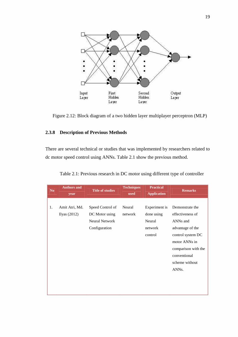
representation of a MLP is shown in Figure 2.12.
19
Figure 2.12: Block diagram of a two hidden layer multiplayer perceptron (MLP)
2.3.8 Description of Previous Methods
There are several technical or studies that was implemented by researchers related to
dc motor speed control using ANNs. Table 2.1 show the previous method.
Table 2.1: Previous research in DC motor using different type of controller
No Authors and
year Title of studies
Techniques
used
Practical
Application Remarks
1.
Amit Atri, Md.
Ilyas (2012)
Speed Control of
DC Motor using
Neural Network
Configuration
Neural
network
Experiment is
done using
Neural
network
control
Demonstrate the
effectiveness of
ANNs and
advantage of the
control system DC
motor ANNs in
comparison with the
conventional
scheme without
ANNs.

20
2.
Jianguo Zhou,
Youyi Wang
and Rujing
Zhou
(2001)
Global Speed
Control of
Separately
Excited DC
Motor
Matlab /
simulink
Using Matlab
/Simulink to
evaluate the
proposed
global speed
controller for
the field
weakening
operation of
the separately
Excited DC
motor.
The global speed
control problem for
a separately excited
DC motor is studied.
The motor was
firstly model in two
local areas, the first
one is a linear model
when speed is under
base speed, and the
other is nonlinear
one when the speed
is above the bases
peed.
3.
MA. Hoque
M.R. Zaman
and M.A
Rahman,
(1995)
Artificial Neural
Network Based
Permanent
Magnet DC
Motor Drives
Neural
network
PM dc motor
drive system
with ANN
speed
controller is
designed.
The ANNs based
PM dc motor drive
system is able to
handle adequately
the parameter
variations and the
changes in load.
4.
M.F. Chouikha
and C.Aissi
(1990)
Designand
implementation
of an intelligent
controller using
neural networks
Neural
network
Investigating
the idea of
using neural
networks for
controlling
complex
systems.
Thus, the controller
is able to use its past
experience to
improve its future
performance. This
approach has two
main advantages:
first it converges in
cases where other
methods have failed.
Second, it is well
suited for deductive
as well as heuristic
reasoning.
Table 2.1 (continued)

CHAPTER 3
METHODOLOGY
3.1 Introduction
The DC motor is the obvious proving ground for advanced control algorithms in
electric drives due to the stable and straight forward characteristics associated with it.
From a control system point of view, the DC motor can be considered as SISO plant,
thereby eliminating the complications associated with a multi-input drive system.
The proposed general block diagram for variable speed Separately excited DC motor
using neural network controller is shown in Figure 3.1.
Figure 3.1: The block diagram of a variable speed neural network Separately Excited
DC motor drive system
3.2 Mathematics modelling
To access the problem formulation the mathematical equation of separately excited
dc motor needs to be understand. The separately excited dc motor model dynamics
are described by a set of electrical and mechanical differential and algebraic equation

in continuous time domain as follows;
(3.1)
) (3.2)
Where,
- rotor speed (rad/sec)
- terminal voltage (V)
- armature current (A)
- load torque (Nm)
J - rotor inertia (N )
KF - torque & back emf constant (N )
- Viscous friction coefficient (Nms)
- Armature and field resistance, (Ω)
Armature and field inductance, (H)
From these equations mathematical model of the DC motor can be created. The
model is presented in Figure 3.2.
Figure 3.2: The mathematical model of a separately DC motor

3.2.1 The conventional control system of DC motor
There are many different methods to synthesize control systems of DC motor, but for
this paper method used ANNs authors presented a conventional control system of DC
motor as shown in Figure 3.3 page.
Figure 3.3: Conventional model of control system DC motor
3.2.2 The control system of DC motor using ANNs
The approach of neural network basically works on the provided priories information
and makes a suitable decision for a given testing input based on the provided training
in formation. This approach is analogous to the human controlling approach where
all the past observations are taken as the reference information and are used as a
decision variable. To obtain such estimation in current DC motor controlling
approach the current DC motor drives are to be improved using such a learning
approach.
In this paper a dual level neural network approach is designed for DC
machine speed controlling. A dual level modelling provides a faster training and
converging as compared to a single level neural modelling. For the realization of a
dual level neural modelling, two-neuro architecture namely ANN-control and ANN-
train is proposed. The 2 models of the control system of DC motor using ANNs is
built with, ANN-train, and ANN-control unit where the network are trained to
emulate a function: ANN-train to estimate the speed, ANN-control to control

terminal voltage. The control system of DC motor using ANNs is presented in the
Figure 3.4.
Figure 3.4: DC motor control model with ANNs
3.2.3 The structure and the process of learning ANNs
ANNs have been found to be effective systems for learning discriminates for patterns
from a body of examples [8]. Activation signals of nodes in one layer are transmitted
to the next layer through links which either attenuate or amplify the signal. ANNs are
trained to emulate a function by presenting it with a representative set of input/output
functional patterns. The back-propagation training technique adjusts the weights in
all connecting links and thresholds in the nodes so that the difference between the
actual output and target output are minimized for all given t raining patterns [9].
In designing and training the ANN is used emulate a function, the only fixed
parameters are the number of inputs and outputs to the ANN, which are based on the
input/output variables of the function. It is also widely accepted that maximum of
two hidden layers are sufficient to learn any arbitrary nonlinearity [10]. However, the
number of hidden neurons and the values of learning parameters, which are equally
critical for satisfactory learning, are not supported by such well-established selection
criteria. The choice is usually based on experience. The ultimate objective is to find a
combination of parameters which gives a total error of required tolerance a
reasonable number of t raining sweep [9,11,12].
The ANN1 structure is shown in Figure 3.5 and ANN2 in Figure 3.6. It
consists of an input layer, output layer and one hidden layer. The input and hidden

45
REFERENCES
1. S.Weerasoorya and M.A Al-Sharkawi “Identification andcontrol of a DC
Motor using back-propagation neuralnetworks” IEEE transactions on Energy
Conversion, Vol.6,No.4 pp663-669, December 1991.
2. T.C. Burg, D. M. Dason, J. Hu, P. Vedagarbba, “Velocity tracking fora
separately excited dc motor without velocity measurement”,Proceeding of the
American Control Conference, pp.1051-1055,1994.
3. W. Leonhard, Control of Electrical Drives, .Td, Springer-Verlag, 1985.
4. Z. Liu and F. Luo, “Nonlinear multi-input multi-output control of dcmotor in
fieldweakening region”, International Conference onElectric Machines and
Drives, pp. 688-690, 1999.
5. M.R. Matausek, B.I. Jeftenic, D.M. Miljkovic, and M.Z. Bebic,
“Gainscheduling control of dc motor drive with field weakening”,
IEEETrans. on Industrial Electronics, pp. 153-162, Feb. 1996.
6. J. M. Ziman, Models of Disorder, Cambridge, Cambridge University Press,
1979.
7. Ben Krose and Patrick Van Der Smagt, An Introduction Neural Network,
Nov 1996.
8. G.M. Scott, Knowledge- Based Artificial Neural Networks for
ProcessModeling andControl, PhD. Thesis, University ofWisconsin, 1993.
9. S.Weerasoorya and M.A Al-Sharkawi "Identification and control of aDC
Motor using back-propagation neural networks" IEEE transactions onEnergy
Conversion, Vol.6, No.4 pp663-669, December 1991.
10. E. Levin, R. Gewirtzman, and G.F. Inbar, "Neural NetworkArchitecture for
Adaptive System Modellinggand Control", Neural Networks,No 4(2) pp 185-
191, 1991.

46
11. D. Psaltis A. Sideris and A.A. Yamamura, "A Multilayered Neural Network
Controller", IEEE Control System Magazine, pp. 17-20, 1988.
12. B. Kosko, Neural Networks and Fuzzy Systems, Prentice-Hall International
Inc, 1992.
13. Cajueiro, D. O., & Hemerly, E.M. (December, 2003). Direct Adaptive
Control Using Feedforward Neural Networks.
14. IEEE Transaction, Volume-51, 1191-1214. DOURATSOS, I., & BARRY, J.
(2007). NEURAL NETWORK BASED MODEL REFERENCE ADAPTIVE.
15. S.G German-Gankin – The computing modeling for power – electronic
systems in Matlab, 2001.
16. Michael Negnevitsky – Artificial Intelligent A Guide to Intelligent systems.
17. Second Edition (2005). ADDISON Wesley Pearson Education Limited, 2002.