specification guide divisions 02 and 03 concrete · pdf file5 • bolt pattern cannot be...
TRANSCRIPT
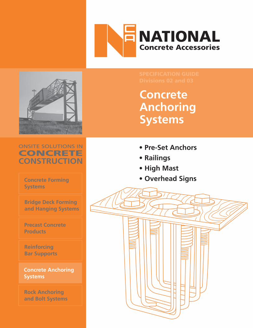
ConcreteAnchoringSystems
• Pre-Set Anchors• Railings• High Mast• Overhead SignsConcrete Forming
Systems
Bridge Deck Formingand Hanging Systems
Precast ConcreteProducts
ReinforcingBar Supports
Concrete AnchoringSystems
Rock Anchoringand Bolt Systems
ONSITE SOLUTIONS IN
CONCRETECONSTRUCTION
SPECIFICATION GUIDEDivisions 02 and 03

GENERAL INFORMATION
1. A qualified person must accurately calculate the applied loads and select the appropriate products and determine compatible spacings.
2. For anchoring and form tying operations, proper installation practices must be maintained. Guidelines for setting mechanical anchors and tensioning procedures for rock bolts are detailed NCA Rock Anchoring and Bolt Systems publication. Failure to follow approved practices, may result in failure.
3. The applied safety factor for a product will depend on the degree of hazard or risk involved in the product application. This safety factor is governed by national codes, local codes and/or by design professionals. Onsite conditions such as poor installation practices or inproper use of equipment could increase the degree of risk. If such conditions exist, the user must increase the safety factor to compensate.
WARNING : Improper, careless and/or haphazard use of the products shown in this document can expose workers to extreme danger, injury and death. If uncertain about installa- tions or use of any NCA product, contact the nearest NCA Sales office or Technical Department for explanations and/or recommendations.
National Concrete Accessories products are manufactured according to strict specifications and are subject to numerous tests under a stringent quality control program. These products are designed to be capable of meeting or exceeding all necessary safety requirements for the concrete construction, anchoring and forming industry. All product test data shown, were obtained through an independent testing facility or tests conducted by NCA. However, the performance of a quality product can be affected by the manner in which it is used in
For catalogue
updates visit
our web site at
www.nca.ca.
1
the field. Therefore, the following precautions should be taken by all involved persons. 4. Any welding required should be performed by a certified welder. Bending or welding of high tensile steel products should not be permitted.
Note: NCA does not warrant any product that has been welded, altered or modified in any way after leaving an NCA plant or warehouse.
5. Never exceed listed product safe working loads. Note that all product load ratings shown in this bulletin are ratings for new or "as new" products only. Extreme caution must be exercised when using any product that is in other than new condition. Any reusable product that shows wear, misuse, overloading, corrosion or any other factor that would compromise its safe working load should be discarded. It is the user's responsibility to continually inspect working hardware for wear, and to discard the parts when wear is noted. DO NOT straighten bent bolts, rather discard and replace.
6. NCA products are not to be applied or installed until the user and/or the installer has a clear understanding of the information contained within the appropriate product publication. All contractors must instruct their employees in the appropriate use and installation of NCA products.
To avoid injury and possible form tie problems DO NOT CLIMB ON FORM TIES.
8. Do not interchange products supplied by other manufacturers with those supplied by NCA. NCA cannot guarantee that products supplied by others will be compatible and/or interchangeable with NCA's quality concrete accessories.
9. Drawings and/or sketches shown in this bulletin are for illustrative purposes only. Check actual conditions for specific applications. Metric values listed are a soft conversion of imperial values.
jik
NOTE: For applications notspecifically identified herein,approval in writing is requiredby the NCA TechnicalDepartment for specialapplications and uses of NCAproducts.
The informationcontained hereinsupersedes all previousversions printed priorto this edition and isbased on data andknowledge consideredtrue and accurate.NCA reserves the rightto update informationwithout notice.
Please read allstatements,recommendationsor suggestions in conjunction withNCA's condition ofsale which apply to all goods supplied byNCA. No statement,recommendationsor suggestions isintended for any usethat would infringeany patent orcopyright.

GENERAL INDEX
2
PRE-SET ANCHORS FORLIGHT & FLAG POLES
Light and Flag Poles ................................... 3
Why Tolerate these Problems? .................... 4
Pre-Set Anchors System ............................... 5
Anchors for Light Poles .............................. 6
Light Pole Anchor Installation .................... 7
Ordering Information ............................... 8
Light Pole Anchor Design ........................... 9
Design Charts ....................... 10, 11, 12, 13, 14
PRE-SET ANCHORS FORRAILINGS
Railings ......................................................... 15
Types and Applications .............................. 16
Ordering Information ................................ 18
Railing Anchor Design ................................ 19
Design Charts ....................................... 20 & 21
Technical Notes ............................................ 22
PRE-SET ANCHORS FORSIGN STRUCTURES
Overhead Signs ............................................ 23
Types and Applications ................................. 24
Ordering Information ................................... 26
High Mast Anchor Design .......................... 27
Design Charts .............................. 28, 29, 30, 31
Foundation Design ...................................... 32
Test Results ................................................... 34
CRANE BOLTS
Crane Anchors .............................................. 36
Crane Anchor Bolts ...................................... 37
ANCHOR BOLTS
Anchor Bolts ................................................ 38
Hook Anchor Bolts ...................................... 39
Wall Plate Anchor ........................................ 39
THREADED RODS
All Thread Bar ............................................... 40
Corrosion Protection Products .................... 40
Through Wall Ty Bar .................................... 41

3
LIGHT ANDFLAG POLES
NCA Preset Anchorage System provides a simple, accurate and economical method for anchoring light poles, railings, guard rails and sign posts to structural concrete.The basic units can be manufactured to conform with any required configuration in size that will accommodate bolts or studs (either hi-strength galvanized or stainless steel) from 13mm to 38mm (1/2" - 1 1/2") in diameter.Laboratory and field tests have shown that these units have load factors that will exceed published design requirements. It has also been found that the coils have a significant effect in the unit's anchoring capacity - and that the unit's design distributes bolt stresses into the concrete. These design features provide more strength per anchorage that can be obtained from most of the conventional materials now used.This strength and guaranteed "bolt pattern" permit the design engineer to approach the problem of fastening appurtenances to structural concrete with complete assurance of performance and over-all economy.The same strength, "bolt pattern", and simplicity of application assure the contractor of and extremely reasonable "first cost" while eliminating many of the problems currently encountered with setting standard anchor bolts.In addition, there is considerable economy when stainless steel is required for protection from rust stain, because with the Preset Anchorage System only the bolts and washers have to be stainless -since the complete anchoring unit is imbedded in the concrete.ACHNOWLEDGEMENT:We wish to thank Morrison Hershfield Limited, Consulting Engineers of Toronto for their advice and engineering services which was invaluable in the preparation of this publication.

4
WHY TOLERATE THESE PROBLEMS...
WHY HAVE PROBLEMS...
...SOLVE THEM WITH PRE-SET ANCHORS
Consult your NCA Sales Representative or theNCA Technical Department for additional information.

5
• Bolt pattern cannot be disturbed as with conventional anchor bolts.
• System provides guaranteed bolt pattern to fit any base plate accurately and can be manufactured to conform to any required configuration.
• Installation of pre-set anchor can save up to 75% of normal labour costs.
• Field adjustments can easily be accommodated with various length studs available with the system.
• If threads on studs are damaged, they can be easily replaced (not possible with standard anchor bolts)
• System is more economical if stainless steel is required as only bolts, washers or studs need be of stainless steel.
Consult your NCA Sales Representative or theNCA Technical Department for additional information.
PRE-SETANCHORS
SYSTEM

6.
The PRE-SET ANCHOR for light poles is furnishedas a complete assembly mounted on a plywood template to facilitate the setting of the anchor.
The Pre-Set Anchor can be supplied with square headed levelling studs to allow for adjustment after installation of the anchor and are designatedby the letter "S", i.e. DGR™-1S or DGR™-2S.
The four Hi-Tensile bolts or studs, four round washers and anchor cage are hot dipped galvanized to ASTM-A 153.
The anchors are available with 20mm(3/4"), 25mm(1"),32mm(1-1/4") or 38mm(1-1/2") diameter bolts or studs. On request, the bolt can be furnished in stainless steel.
Standard length bolts are supplied to accom-modate base plates up to 25mm(1") thick. Longer bolts can be supplied for thicker base plates.
PRE-SET™ ANCHOR for light Type DGR™-_____ by NCA shall be used to fasten poles to concrete foundations. Complete unit shall be hot dipped galvanized to ASTM-A 153 Spec. Bolts are to be given a liberal coating of white non-staining grease. A 20mm(3/4") thick setting template shall be furnished to accurately position the anchor within the form.
SPECIFICATIONS
Type DGR -1 for standard applicationTM
TM
TM
ANCHORS FOR LIGHT POLES
Type DGR -2 for aashto requirements
Type DGR -2S(with squared end studs)
Consult your NCA Sales Representative or theNCA Technical Department for additional information.
Anchorage Assembly, Light PolesPreset Anchors - DGR- OPSD 2215.0200 - Anchorage Assembly- OPSD 2216.0100 - Anchorage Assembly for Pole Footing in Concrete Barrier.
OPS-PMC ACCEPTED FOR USE

TYPICALLIGHT POLES
INSTALLATION
7
Typcial installation pre-set anchor with bolts as per Toronto spec. 807.015
Typical installation pre-set anchor with studs as per MTO spec. OPSD 2215.02 & OPSD 2215.02
(Previously known as MTO spec. OPSD 2428.03)
Consult your NCA Sales Representative or theNCA Technical Department for additional information.

LIGHT POLE ANCHOR ORDERINGINFORMATION
8
TYPE OF ANCHOR .…………..DGR -
QUANTITY REQUIRED…………….....
BOLT……….. STUD....……
BOLT OR STUD DISTANCE .……..(A)
BOLT OR STUD DISTANCE ……...(B)
DEPTH OF ANCHOR……………...(C)
BOLT OR STUD DIAMETER …..... (D)
WIDTH OF TEMPLATE…………....(E)
LENGTH OF TEMPLATE ………...(L1)
LENGTH OF TEMPLATE ………...(L2)
LOCK WASHERS…...………………....
NYLON BUSHING……………………..
A
D
B
L1 L2
E
PLYWOOD SETTING TEMPLATE
2 ROUND WASHERS AND 2 HEX NUTS PER STUD
FERRULEOR COIL
HI-TENSILE BOLT AND ROUND WASHEROR
ORDER FORMPhotocopy this page and send to NCA Customer
Service with required dimensions.
Consult your NCA Sales Representative or theNCA Technical Department for additional information.
TM

PRE-SETANCHOR DESIGN
9
A light pole anchor assembly and foundation are required for the 11m (36' - 1") pole shown. Design for NBC 1995 wind pressure, q 1/30.
Location: Edmonton Allowable lateral soil pressure: 67kPa (1400 psf 9.72psi)WIND LOADS:Q1/30 = 0.40kPa (8.4 psf) = (0.058 psi) Pole Height, Pole Height, hp = 11.0m (36'-1") Radial ice, Ri = 13mm (1/2") Pole Arm , Rp = 2.5m (8'-2 1/2") Pole diameter, dp = 200mm (8")Arm diameter, da = 100mm (4")Lamp effective projected area, A = 0.30m2 (3.23 sq.ft, = 465 sq.in)Wind pressure, W = q Ce Cg Cf
Ce = 1.0 (average from Table 4.1.8A NBC 1995)Cg = 2.5 (for small elements NBC 1995)Cf = 1.1 (Figure B-15 Supplement NBC 1995) Say C =1.1, (C = Varies)
Wind force on pole, W = q C C C ( )
= (0.40) (1.0) (2.5) (1.1) (0.20+0.026) (11.0)
= 2.74 kN (0.62 kips)
Wind force on arms, W = q C C C (d + )
= (0.40) (1.0) (2.5) (1.1) (0.10+0.026) (5.0)
= 0.69kN (0.16 kips)
Wind force on lamps, W = (0.40) (1.0) (2.5) (1.0) (0.3) (2)
= 0.60 kN (0.13 kips)
Total Applied Base Shear, V = 2.74 + 0.69 + 0.60 = 4.0Kn (0.91 kips)
Total Applied Base Moment, M = (2.74) (11.0) (0.5) + (0.69) (11.0) + (0.60) (11.0) = 29.0kNm (257 kip-inch) = (21.42 kip-ft)NOTE: Torsion produced by unbalanced wind load will be neglected.SOLUTION: Try using a DGR™-2 NCA Pre-Set Anchor and a 600 mm (2') diameter bored concretepile. Enter Design Aid Sheet, with base shear = 4.0kN and base moment = 29.0 kNm.
For pile diameter = 600mm (2'-0")Use pile depth = 2500mm (8' - 2 1/2")The bolt circle diameter = 300mm (1'-0")Minimum anchor length = 400mm (16")Minimum bolt size = 25mm (1") dia. A325
5000mm(16'-4 3/4")
(36'
-1")
1100
0mm
A
ff
e i x hdp +2 x R p1000f
L
g
p
p
i x he2 x R
a 1000fg
f Lge= q C C C A x 2L
A Lp= W + W + W
2 Lp pA pp= (W x h / + W + h + W x h )/1000

10
FORCES FROM SPECIFIED LOAD
80
70
60
50
40
30
20
10
(51.7)
(44.3)
(36.9)
(29.5)
(22.1)
(14.8) (7.4)
120
110
100
90
10 20 30 40 50 60 (2.25) (4.5) (6.75) (9.0) (11.25) (13.5)
400 mm (15 3/4")
APPLIED SHEAR kN (Kips)
PILE DIAMETER = 600mm (24")
BORED CONCRETE PILEREINFORCING: 8-20 M BARS (8 - #6 BARS) 10 M TIES AT 400 mm (#4 @ 16")MATERIALS: CONC. f'c = 20 MPa (3000 psi) REINF. = 400 MPa (60000 psi)
350 mm (13 3/4") 300 mm (11 3/4") 250 mm (9 7/8") 200 mm (7 7/8")
FORCES FROM SPECIFIED(i.e. UNFACTORED) LOAD
APPL
IED
MO
MEN
T kN
• m
(Kip
s - f
t.)
0 0
MOMENT4 - A325 BOLTS (MIN.)
SHEAR
75mm (3") MIN. COVER
BOLT CIRCLE DIAMETERC
G
G = 1500 mm
(5'- 5") G = 2000 m
m
(6'- 6") G = 2500 m
m
(8'- 3") G
= 3000 mm
(9'- 10")
Bolt CircleDiameter
Minimum AnchorLength C
400 (15 3/4")350 (13 3/4")300 (11 3/4")250 (9 7/8")200 (7 7/8")
450 (17 3/4")450 (17 3/4")400 (15 3/4")350 (13 3/4")300 (11 3/4")
Anchor Type: DGR -2Strut Material: C-1030Bored ConcretePile Diameter: 600mm (24")Min. Bolt Size: 20mm (3/4")Allowable LateralSoil Pressure: 67 kPa (1400psf)
BOLT CIRCLE DIAMETER
Consult your NCA Sales Representative or theNCA Technical Department for additional information.
(66.5)
(59.1)
(74.0)
(81.4)
(88.8)TM

11
FORCES FROMSPECIFIED LOAD
80
70
60
50
40
30
20
10
120
110
100
90
10 20 30 40 50 60
400 mm (15 3/4") 450 mm (17 3/4")
BOLT CIRCLE DIAMETER
PILE DIAMETER = 750 mm (29 1/2")
BORED CONCRETE PILEREINFORCING: 8-20 M BARS (8 - #6 BARS) 10 M TIES AT 400 mm (#4 @ 16")MATERIALS: CONC. f'c = 20 MPa (3000 psi) REINF. = 400 MPa (60000 psi)
350 mm (13 3/4") 300 mm (11 3/4") 250 mm (9 7/8") 200 mm (7 7/8")
APPLIED SHEAR kN (Kips)FORCES FROM SPECIFIED(i.e. UNFACTORED) LOAD
APPL
IED
MO
MEN
T kN
• m
(Kip
s - f
t.)
00
MOMENT4 - A325 BOLTS (MIN.)
SHEAR
75mm (3") MIN. COVER
BOLT CIRCLE DIAMETERC
G
G = 1500 mm G = 2000 mm
G = 2500 mm
G
= 3000 mm
Bolt CircleDiameter
Minimum AnchorLength C
450 (17 3/4")400 (15 3/4")350 (13 3/4")300 (11 3/4")250 (9 7/8") 200 (7 7/8") 300 (11 3/4")
450 (17 3/4")450 (17 3/4")450 (17 3/4")400 (15 3/4")350 (13 3/4")
Anchor Type: DGR -2Strut Material: C-1030Bored ConcretePile Diameter: 750mm (29 1/2")Min. Bolt Size: 20mm (3/4")Allowable LateralSoil Pressure: 67 kPa (1400psf)
(9'- 10")
(8'- 3")
(6'- 6")
(5'- 0")
(2.25) (4.50) (6.8) (9.0) (11.25) (13.5)
(51.7)
(44.3)
(36.9)
(29.5)
(22.1)
(14.8) (7.4)
Consult your NCA Sales Representative or theNCA Technical Department for additional information.
(66.5)
(59.1)
(74.0)
(81.4)
(88.8)TM

12
FORCES FROM SPECIFIED LOAD
80
70
60
50
40
30
20
10
120
110
100
90
10 20 30 40 50 60
350 mm (13 3/4")
400 mm (15 3/4")
APPLIED SHEAR kN (Kips)
BORED CONCRETE PILEREINFORCING: 8-20 M BARS 10 M TIES AT 400 mm (15 3/4")MATERIALS: CONC. f'c = 20 MPa (3000 psi)REINF. f'c = 400 MPa (60000 psi)
300 mm (11 3/4")
250 mm (9 7/8")
200 mm (7 7/8")
FORCES FROM SPECIFIED(i.e. UNFACTORED) LOAD
APPL
IED
MO
MEN
T kN
• m
(Kip
s - f
t.)
00
MOMENT4 - A325 BOLTS (MIN.)
SHEAR
75mm (3") MIN. COVER
BOLT CIRCLE DIAMETERC
G
G = 1500 mmG = 2000 m
mG = 2500 m
mG
= 3000 mm
Bolt CircleDiameter
Minimum AnchorLength C
400 (15 3/4")350 (13 3/4")300 (11 3/4")250 (9 7/8")200 (7 7/8")
450 (17 3/4")450 (17 3/4")400 (16 3/4")350 (13 3/4")300 (11 3/4")
Anchor Type: DGR -2Strut Material: C-1030Bored ConcretePile Diameter: 600mm (2'-0")Min. Bolt Size: 25mm (1")Allowable LateralSoil Pressure: 67 kPa (1400psf)
BOLT CIRCLE DIAMETER
PILE DIAMETER = 600 mm (24")
(2.25) (4.50) (6.75) (9.0) (11.25) (13.50)
(51.7)
(44.3)
(36.9)
(29.5)
(22.1)
(14.8) (7.4)
(5'-0") (6'-6") (8'-3") (9'-3")
Consult your NCA Sales Representative or theNCA Technical Department for additional information.
(66.5)
(59.1)
(74.0)
(81.4)
(88.8)TM

13
FORCES FROMSPECIFIED LOAD
80
70
60
50
40
30
20
10
120
110
100
90
10 20 30 40 50 60
400 mm (15 3/4") 450 mm (17 3/4")
APPLIED SHEAR kN (kips)
350 mm (13 3/4") 300 mm (11 3/4") 250 mm (9 7/8") 200 mm (7 7/8")
FORCES FROM SPECIFIED(i.e. UNFACTORED) LOAD
APPL
IED
MO
MEN
T kN
• m
(Kip
s - f
t.)
00
MOMENT4 - A325 BOLTS (MIN.)
SHEAR
75mm (3") MIN. COVER
BOLT CIRCLE DIAMETERC
G
G = 1500 mm G = 2000 m
m
G = 2500 mm
G
= 3000 mm
Bolt CircleDiameter
Minimum AnchorLength C
450 (17 3/4")400 (15 3/4")350 (13 3/4")300 (11 3/4")250 (9 7/8") 200 (7 7/8") 300 (11 3/4")
450 (17 3/4")450 (17 3/4")450 (17 3/4")400 (15 3/4")350 (13 3/4")
Anchor Type: DGR -2Strut Material: C-1030Bored ConcretePile Diameter:750mm(29 1/2")Min. Bolt Size: 25mm (1")Allowable LateralSoil Pressure: 67 kPa (1400psf)
BORED CONCRETE PILEREINFORCING: 8-20 M BARS (8 - #6 BARS) 10 M TIES AT 400mm (15 3/4")MATERIALS: CONC. f'c = 20 MPa (3000 psi) REINF. = 400 MPa (60000 psi)
BOLT CIRCLE DIAMETER
PILE DIAMETER = 750mm (29 1/2")
(2.25) (4.50) (6.75) (9.00) (11.25) (13.50)
(51.7)
(44.3)
(36.9)
(29.5)
(22.1)
(14.8) (7.4)
(5'-0") (6'-6")
(8'-3")
(9'-10")
Consult your NCA Sales Representative or theNCA Technical Department for additional information.
(66.5)
(59.1)
(74.0)
(81.4)
(88.8)TM

14
FORCES FROM SPECIFIED LOAD
80
70
60
50
40
30
20
10
120
110
100
90
10 20 30 40 50 60
400 mm (15 3/4")
450 mm (17 3/4")
APPLIED SHEAR kN (Kips)
350 mm (13 3/4")
300 mm (11 3/4")
250 mm (9 3/4")
200 mm (7 3/4")
FORCES FROM SPECIFIED(i.e. UNFACTORED) LOAD
APPL
IED
MO
MEN
T kN
• m
(Kip
s - f
t.)
00
MOMENT4 - A325 BOLTS (MIN.)
SHEAR
75mm (3") MIN. COVERBOLT CIRCLE DIAMETER
C
GG = 1500 mm
G = 2000 mm
G = 2500 m
m
G = 3000 m
m
BORED CONCRETE PILEREINFORCING: 8-20 M BARS 10 M TIES AT 400 mm (15 3/4")MATERIALS: CONC. f'c = 20 MPa (3000 psi)REINF. f'c = 40 MPa (60000 psi)
Bolt CircleDiameter
Minimum AnchorLength C
450 (17 3/4")400 (15 3/4")350 (13 3/4")300 (11 3/4")250 (9 7/8") 200 (7 7/8") 300 (11 3/4")
450 (17 3/4")450 (17 3/4")450 (17 3/4")400 (15 3/4")350 (13 3/4")
Anchor Type: DGR -2Strut Material: C-1030Bored ConcretePile Diameter: 1000mm (39")Min. Bolt Size: 25mm (1")Allowable LateralSoil Pressure: 67 kPa (1400psf)
BOLT CIRCLE DIAMETER
PILE DIAMETER = 1000mm (40")
(2.25) (4.50) (6.75) (9.00) (11.25) (13.50)
(51.7)
(44.3)
(36.9)
(29.5)
(22.1)
(14.8) (7.4)
(5'-0") (6'-6")
(8'-3")
(9'-3")
Consult your NCA Sales Representative or theNCA Technical Department for additional information.
(66.5)
(59.1)
(74.0)
(81.4)
(88.8)TM

15
Consult your NCA Sales Representative or theNCA Technical Department for additional information.
RAILINGS

16
PRE-SET ANCHOR FOR RAILINGSThe PRE-SET ANCHOR for railings is furnished as a complete assembly mounted on a plywood template to facilitate the setting of the anchor.
The four Hi-Tensile bolts, four round washers and the anchor cage are hot dipped galvanized to ASTM-A 153.
The anchors are available with 12mm (1/2"), 20mm (3/4") or 25mm (1") diameter bolts and onrequest, bolts and washers can be furnished in stainless steel.
Nylon bushings in conjunction with galvanizedfinished bolts are recommended when used with aluminum guard rails to prevent any chemical reaction.
PRE-SET ANCHORS for railings can be furnished in bright wire upon request.
SPECIFICATIONS FOR ANCHORPRE-SET™ ANCHOR for railings TYPE DGR™-____ by NCA or an approved equal shall be used tosecure guard rails or railings to the concrete. Hi-Tensile bolts and round washers shall be hot dipped galvanized to ASTM-A 153 and be given a liberal coating of white non-staining grease. A 12mm (1/2") thick setting template shallbe furnished with the anchor for accurate positioning.
RAILINGANCHORS
Type DGR -2 for Aashto requirements
Type SGR for 2 hole railing posts
Type DGR -1 for standard applications
Consult your NCA Sales Representative or theNCA Technical Department for additional information.
OPS-PMC ACCEPTED FOR USEAnchorage, Barrier Wall RailingPreset Anchors - DGR & SGR- OPSS 908 - Steel Barrier Rail & Pedestrian Handrail- SS110-21 - Railing For Barrier/Parapet Wall
TM
TM
TM

17
Consult your NCA Sales Representative or theNCA Technical Department for additional information.
TM
TM
20mm (3/4") Ø ST. ST. BOLT150mm (6") DEEP180mm (7") X 300mm (11 7/8")
DGR -120mm (3/4") Ø BOLT150mm (6") DEEP180mm (7") X 300 mm (11 7/8")
SGR -112mm (1/2") Ø BOLT300mm (11 7/8") DEEP
RAILINGANCHORS

18
RAILINGORDERINGINFORMATION
A
D
B
L1 L2
E
HI-TENSILE BOLT& ROUND WASHER
STAINLESS STEEL BOLT& NYLON WASHER OR
Photocopy this page and send to NCA Customer Service with required dimensions.
Consult your NCA Sales Representative or theNCA Technical Department for additional information.
ORDER FORM
TYPE OF ANCHOR .……….................................…...
QUANTITY REQUIRED……….......................…….....
BOLT DISTANCE .…........................................…..(A)
BOLT DISTANCE ..........................................….... (B)
DEPTH OF ANCHOR…….......................………...(C)
BOLT DIAMETER...........................................…... (D)
WIDTH OF TEMPLATE…….......................……....(E)
LENGTH OF TEMPLATE …….......................…...(L1)
LENGTH OF TEMPLATE …….......................…...(L2)
STAINLESS STEEL BOLT…...…..........……………....
NYLON BUSHING ……….......................……………..

19
A railing anchorage is required for the Guard Rail shown, loaded in accordance with CAN3-S6-00, design for highway bridges.
Total applied base shear: 45kN (10.1 kips)Total applied base moment: 23.6 kN.m (208.9 kips - inch)
Referring to CAN-S6-00 Limit states design4LS Combination 1
P = 1.7 x L /0.95 = 1.79 x L This indicates a load factor of 1.79, which is greater than the loadfactor of 1.7 used in the NCA design aids.* Therefore increase the applied base shear and basemoment by 1.79/1.7 = 1.05.
Total applied base shear now becomes (45) (1.05) = 47.25 kN (10.62 kips)Total applied base moment now becomes (23.6) (1.05) = 31.71kN.m (280.7 kips - inch)
* see technical notes pg 22.
SOLUTION
Try using a DGR™-2 NCA Pre-Set Anchor with 4 – 20 mm diameter A325 Bolts. Enter design aid sheet, page 21, with baseshear 47.25 kN (10.62 Kips) and base moment 31.71kN.m (280.7 kips - inch).Minimum center to center bolt spacing: 250mm (9 3/4").Minimum anchor Depth: 300mm (11 7/8").
22.5 kN
PARAPET REINFORCEMENT BY OTHERS
22.5 kN(5000 lbs.)
(5000 lbs.)
700
mm
(27.
5")
300
mm
(11
7/8"
)
RAILINGDESIGN
f
Consult your NCA Sales Representative or theNCA Technical Department for additional information.

20
FORCES FROM SPECIFIED LOAD
10
20
30
40
50
60
20 40 60 80 100 120(4.50) (9.00) (13.50) (18.0) (22.5) (27.0) (31.5) (36.0) (40.5) (45.0) (49.5)
(44.3)
(36.9)
(29.5)
(22.1)
(14.8)
(7.4)
140 160 180 200 220
APPLIED SHEAR kN FORCES FROM SPECIFIED(i.e. UNFACTORED) LOAD
APPL
IED
MO
MEN
T kN
Ô m
(Kip
s - f
t.)
00
70
80
A = 100mm (4.0")
A = 150mm (6.0")
A = 200mm (7 3/4")
A = 250mm (9 3/4")
A = 300mm (11 3/4")
SHEAR
MOMENT
CONCRETE PARAPET90mm (3 1/2") MIN.
BC
A
Anchor Type: DGR -1 Anchor Bolts: 20mm (3/4") dia. A325 Concrete Strength: f’c = 20 Mpa Wire Struts: C-1030
A = see graph for required minimum dimensionB = as requiredC = 300mm (11 3/4") min.
NOTES:1. Designer to determine reinforcing requirements for parapet.2. Capacity determined by tensile strength of wire struts to resist moment by direct tension and to resist by shear friction (see Technical Notes).
(Kips)
Consult your NCA Sales Representative or theNCA Technical Department for additional information.
(59.1)
(51.7)
TM

21
FORCES FROMSPECIFIED LOAD
10
20
30
40
50
60
20 40 60 80 100 120 140 160 180 200 220
APPLIED SHEAR kN (Kips) FORCES FROM SPECIFIED(i.e. UNFACTORED) LOAD
APPL
IED
MO
MEN
T kN
• m
(Ki
ps -
ft.)
00
70
80
A = 100mm (4.0")
A = 150mm (6.0")
A = 200mm (7 3/4")
A = 250mm (9 3/4")
A = 300mm (11 3/4")
SHEAR
MOMENT
CONCRETE PARAPET90mm (3 1/2") MIN.
BC
A
Anchor Type: DGR -1 Anchor Bolts: 20mm (3/4") dia. A325 Concrete Strength: f’c = 20 MPa Wire Struts: C-1030
A = see graph for required minimum dimensionB = as requiredC = 300mm (11 3/4") min.
NOTES:1. Designer to determine reinforcing requirements for parapet.2. Capacity determined by tensile strength of wire struts to resist moment by direct tension and to resist by shear friction (see Technical Notes).
(4.50) (9.00) (13.50) (18.0) (22.5) (27.0) (31.5) (36.0) (40.5) (45.0) (49.5)
(44.3)
(36.9)
(29.5)
(22.1)
(14.8)
(7.4)
Consult your NCA Sales Representative or theNCA Technical Department for additional information.
(59.1)
(51.7)
TM

22
TECHNICAL NOTESGUARDRAIL ANCHORS
f
1. SLAB AND PARAPET REINFORCEMENT The design aids developed for the NCA guardrail anchors do not include guidelines for the general
reinforcement of the parapet or slab to which the guardrails are attached. Therefore, the designer is required to detail the necessary reinforcement in the parapet or slab by standard methods.
2. GUARDRAIL ANCHOR CAPACITIES Several possible failure mechanisms were considered in the development of the design aids. These included:
a) Failure of the ASTM-A325 fasteners in combined shear and tension b) Anchorage failure in the concrete associated with the embedment length and edge distance of the anchor struts. c) Tensile failure of the anchor struts due to applied shear and moment.
It was found that the latter failure mechanism, tensile failure of the anchor struts was critical. In this failure mode, it is assumed that the anchor struts must resist both tension forces due to overturning moments and tension forces due to shear. The tension forces caused by shear correspond to the "shear friction" concept set forth in CSA Standard A23.3-94. In this model, the applied shear is resisted across the plane between the base plate and the concrete parapet by friction. The clamping force necessary to create the required frictional shear forces is provided by the DGR™ anchor struts which are perpendicular to the assumed slip plane.
3. LOAD FACTORS The capacities of the DGR™ type guardrail anchors are given by a series of sloping lines in design aids. The capacities were computed by dividing the theoretical ultimate resistance of the anchors by a factor of 1.79, which corresponds to the live load of and resistance factor of 0.95 specified in CSA StandardCSA-S6-00. When using design standards other than CSA S6-00, it is still possible to utilize the NCA design aids by multiplying the unfactored loads by the ratio L /1.79 and entering the design charts with these modified values (L is equal to the load factor in a design standard other than CSA CSA-S6-00).
f
Consult your NCA Sales Representative or theNCA Technical Department for additional information.

23
OVERHEADSIGN STRUCTURES
Consult your NCA Sales Representative or theNCA Technical Department for additional information.

24
The PRE-SET ANCHOR for sign posts and overhead sign supports is furnished as a complete assembly mounted on plywoodtemplates to facilitate the setting of the anchor. A 20mm (3/4") lagstud maintains correct spacing of anchorage.
The Hi-Tensile bolts, round washers and theanchor are hot dipped galvanized toASTM-A 153.
The anchors are available with 20mm (3/4"), 25mm (1"), 32mm (1-1/4") and 38mm (1-1/2") diameter bolts or square headed leveling studs. On request the bolts or studs can be furnished in stainless steel.
The OSP Type Pre-Set Anchor is used to secure high mast light poles or sign posts. Special configurations are available upon request. Send a detailed drawing of anchor required to NCA Technical Department.
SPECIFICATIONS FOR ANCHORPRE-SET ANCHOR, Type _______by NCA or an approved equal shall be used to secure sign posts to the concrete. Hi-Tensile bolts andround washers shall be hot dipped galvanized to ASTM-A 153 and be given a liberal coatingof white non-staining grease. A 20mm (3/4")thick setting template shall be furnished with the anchor for accurate positioning.
MISCELLANEOUSPRE-SET ANCHORS
TYPE OSP -8
TYPE DSP -4
TYPE DSP -8
Consult your NCA Sales Representative or theNCA Technical Department for additional information.
TM
TM
TM
TM
Anchorage Assembly, Sign Support, TrichordPreset Anchors - OSP- OPSS 915 - Sign Support Structures
OPS-PMC ACCEPTED FOR USE

25
75 DIA. HOLE100 DIA. HOLE
760 76
0
510
500
ELEVATION
ROUND WASHER
PLYWOODTEMPLATE
32 DIA. X 115 LG. BOLT
920
(2'-
6")
(1'-
8")
(2'-
6")
(3'- ")4/1
(1'-7
") 4 /3
(1'-
6") (1'-
8")
(6") (3") (10 ")2/1(3'-6 ")8/1
(7
")2 /1
1220(4'-0")
32 DIA. X 120 LG. BOLTROUND WASHERPLYWOOD TEMPLATE 265
190
460 51
0
20 X 1500 LG.LAGSTUD
75 DIA. HOLEELEVATION
751070150
SPECIFICATIONSFOR ANCHOR
32 DIA. X 120 LG. BOLTROUND WASHER
PLYWOOD TEMPLATE
175 ELEVATION
75 DIA. HOLE20 X 1575 LG.LAGSTUD
250
460(
1'-6
")
300
460
1040 90180(7")
(18")(3 ")2/1
(6 ")8/7
(11
")
4 /3
1220(4'-0")
(10"
)
Consult your NCA Sales Representative or theNCA Technical Department for additional information.

ANCHORORDERINGINFORMATION
26
TYPE DSP -4
TYPE DSP -8
TYPE OSP -8
SPACING
REBAR SPACER
REBAR SPACER
C
G
HB
FE
SPACINGF G
CE H
A
E F
G H
C
B.C.D
TYPE OF ANCHOR ……………………………….
QUANTITY REQUIRED …………………………..
BOLT………….... or STUD…………...….
BOLT OR STUD DISTANCE …………………(A)
BOLT OR STUD DISTANCE .………………...(B)
DEPTH OF ANCHOR .…………………………(C)
ANCHOR SPACING .……………………………..
BOLT CIRCLE DIAMETER .………………(BCD)
BOLT OR STUD DIAMETER .………………..(D)
WIDTH OF TEMPLATE .………………………(G)
LENGTH OF TEMPLATE .…………………….(E)
LENGTH OF TEMPLATE ..……………………(F)
REBAR SPACER LENGTH ..…………………….
LOCK WASHERS ..……………………………….
NYLON BUSHING .……………………………….
ORDER FORM
Consult your NCA Sales Representative or theNCA Technical Department for additional information.
D
D
D
TM
TM
TM

27
A light pole anchor assembly and foundationare required for the 30.5 m (100 foot) pole shown. Use NBC 1995 wind pressure, q 1/30.
Location: CalgaryAllowable lateral soil pressure: 67 kPa (1400 psf 9.72 psi)
Q1/30, q = 0.46kPa (9.6 psf = 0.07 psi) Pole Height, hp = 30.50 (100')Radial Ice, R = 13 mm (1/2")Pole diameter, dp = 330 mm (1'-1")Lamp effective, A Projected area = 0.75m2 (1162 sq.in.)
Wind Pressure, W = q Ce Cg CfCe = 1.1 (average from table 4.1.8 NBC 1995)Cg = 2.5 (for small elements NBC 1995)Cf = 1.1 (Figure B-18 Supplement NBC 1995) CAN/CSA 537-01 (C Varies)
Wind force on pole, Wp = q x Ce Cg Cf x (dp + 2 x Ri) x hp
Cf = 1.1 Wp = (0.46) (1.1) (2.5) (Cf) (0.33+0.026) (30.5) = 15.1 kN (3.40 kips)
Wind force on lamps, Wp = (0.46) (Cf) (2.5) (1.0) (0.75) Cf = 1.1 Wp = 1.0kN(0.225 kips)
Total Applied Base Shear, V = Wp + W2 V = 15.1 + 1.0 = 16.1kN (3.625 kips)Total Applied Base Moment, M = Wp x hp/2 + W2 x hp =(15.l) (30.5) (0.5) + (1.0) (30.5) M =261kNm (192.5 kips)
NOTE: torsion produced by unbalanced wind load will be neglected.
SOLUTION: Try using a OSP-8 NCA Pre-Set Anchor and a 1200 mm(3'-11 1/4") diameter bored concrete pile.
Enter Design Aid Sheet, page 31, with base shear = 16.1kN and base moment = 261 kNm.
For pile diameter = 1200 mm (3'-11 1/4")Use pile depth = 4500 mm (14'-9 1/8")Use bolt circle diameter = 750 mm (2'-5 1/2")Minimum anchor length = 850 mm (2'-9 1/2")Minimum bolt size = 38 mm (1 1/2") dia. A325
HIGH MAST ANCHORDESIGN EXAMPLE
3050
0mm
(100
')
WIND LOADS:
f
L
i
1000
Consult your NCA Sales Representative or theNCA Technical Department for additional information.
Anchorage Assembly, High Mast Light PolesPreset Anchors - HM- MTOD 2453.0500 - High Mast Lighting Pole Anchorage Assembly Details- OPSD 2216.0100 - Anchorage Assembly for Pole Footing in Concrete Barrier- OPSD 2456.0110 - High Mast Lighting Pole Anchorage Assembly Details- OPSS 2474 - High Mast Pole Anchorage Assembly- OPSS 631 - Concrete Footings - High Mast Poles

28
FORCES FROM SPECIFIED LOAD
4 - A325 BOLTS (MIN.)MOMENT
SHEAR
75mm (3") MIN. COVERBOLT CIRCLE DIAMETER
C
G
50
100
150
200
250
300
350
400
450
500
20 40 60 80 100 120
550mm (1'-9 5/8") BOLT CIRCLE DIAMETER
APPLIED SHEAR kN (Kips)
PILE DIAMETER = 900mm (2'-11 1/2")
BORED CONCRETE PILEREINFORCING: 8-25 M BARS 6-10 M TIES AT 200mm (7 7/8") REMAINDER AT 400mm (15 3/4")MATERIALS: CONC. f'c = 20 MPa (3000psi) REINF. = 400 MPa (60000psi)
FORCES FROM SPECIFIED(i.e. UNFACTORED) LOAD
APPL
IED
MO
MEN
T kN
• m
(Ki
ps -
ft.)
00
G = 2500mm (8'-3")
G = 3000mm (9'-3")
G = 3500mm (11'-6")
G = 4000mm
(13'-1 1/2")
Bolt Circle
DiameterBolt
Diameter
Min. Anchor
Length C550
(21 5/8")32
(1 1/4")850
(33 1/2")
(4.50) (9.00) (13.50) (18.0) (22.5) (27.0)
(36.9)
(73.8)
(110.6)
(147.5)
Consult your NCA Sales Representative or theNCA Technical Department for additional information.
(184.4)
(221.3)
(258.1)
(295.0)
(331.9)
(368.8)
Anchor Type: OSP -8Strut Material: C-1030Bored ConcretePile Diameter: 900mm (35.5")Allowable LateralSoil Pressure: 67 kPa (1400psf)
TM

29
FORCES FROM SPECIFIED LOAD
4 - A325 BOLTS (MIN.)MOMENT
SHEAR
75mm (3") MIN. COVERBOLT CIRCLE DIAMETER
C
G
50
100
150
200
250
300
350
400
450
500
20 40 60 80 100 120
550mm (1'-9 5/8") BOLT CIRCLE DIAMETER
APPLIED SHEAR kN (Kips)
PILE DIAMETER = 1000mm (3'-3 3/8")
BORED CONCRETE PILEREINFORCING: 8-25 M BARS 6-10 M TIES AT 200mm (7 7/8") REMAINDER AT 400mm (15 3/4")MATERIALS: CONC. f'c = 20 MPa (3000psi) REINF. = 400 MPa (60000psi)
FORCES FROM SPECIFIED(i.e. UNFACTORED) LOAD
APPL
IED
MO
MEN
T kN
• m
(Kip
s - f
t.)
00
G = 2000mm (6'-6 3/4")
G = 2500 mm (8'-3")
G = 3000 mm (9'-3")
G = 3500mm (11'-6")
G = 4000mm
(13'-1 1/2")
Bolt Circle
DiameterBolt
Diameter
Min. Anchor
Length C550
(21 5/8")32
(1 1/4")850
(33 1/2")650
(25 1/2")32
(1 1/4")850
(33 1/2")
(4.50) (9.00) (13.50) (18.0) (22.5) (27.0)
(36.9)
(73.8)
(110.6)
(147.5)
Consult your NCA Sales Representative or theNCA Technical Department for additional information.
(184.4)
(221.3)
(258.1)
(295.0)
(331.9)
(368.8)
650mm (25 5/8")
Anchor Type: OSP -8Strut Material: C-1030Bored ConcretePile Diameter: 1000mm (39")Allowable LateralSoil Pressure: 67 kPa (1400psf)
TM

30
FORCES FROM SPECIFIED LOAD
4 - A325 BOLTS (MIN.)MOMENT
SHEAR
75mm (3") MIN. COVERBOLT CIRCLE DIAMETER
C
G
50
100
150
200
250
300
350
400
450
500
20 40 60 80 100 120
550mm (21 5/8")
650mm (25 5/8")
APPLIED SHEAR kN (Kips)
750mm (29.5") BOLT CIRCLE DIAMETERPILE DIAMETER = 1100 mm (43 3/8")
BORED CONCRETE PILEREINFORCING: 10-25 M BARS 6-10 M TIES AT 200mm (7 7/8") REMAINDER AT 400mm (15 3/4")MATERIALS: CONC. f'c = 20 MPa (3000psi) REINF. = 400 MPa (60000psi)
FORCES FROM SPECIFIED(i.e. UNFACTORED) LOAD
APPL
IED
MO
MEN
T kN
• m
(Kip
s - f
t.)
00
G = 2000mm (6'-6")
G = 2500mm (8'-3")
G = 3000mm (9'-3")
G = 3500mm (11'-6")
G = 4000mm
(13'-1 1/2)
G = 4500mm
(14'-9 1/4")
G = 5000mm
(16'-4 7/8")
(4.50) (9.00) (13.50) (18.0) (22.5) (27.0)
(36.9)
(73.8)
(110.6)
(147.5)
(184.4)
(221.3)
(258.1)
(295.0)
(331.9)
(368.8)
Bolt Circle
DiameterBolt
Diameter
Min. Anchor
Length C550
(21 5/8")32
(1 1/4")850
(33 1/2")650
(25 1/2")32
(1 1/4")850
(33 1/2")750
(29 1/2")38
(1 1/2")850
(33 1/2")
Consult your NCA Sales Representative or theNCA Technical Department for additional information.
Anchor Type: OSP -8Strut Material: C-1030Bored ConcretePile Diameter: 1100mm (43 3/8")Allowable LateralSoil Pressure: 67 kPa (1400psf)
TM

31
FORCES FROMSPECIFIED
LOAD
4 - A325 BOLTS (MIN.)MOMENT
SHEAR
75mm (3") MIN. COVERBOLT CIRCLE DIAMETER
C
G
50
100
150
200
250
300
350
400
450
500
20 40 60 80 100 120
550mm
550mm (21 5/8")
650mm (25 5/8")
BOLT CIRCLE DIAMETER
APPLIED SHEAR kN (Kips)
PILE DIAMETER = 1000mm (39 3/8")
750mm (29.5") BOLT CIRCLE DIAMETERPILE DIAMETER = 1100 mm (43 3/8")
BORED CONCRETE PILEREINFORCING: 10-25 M BARS 6-10 M TIES AT 200mm (7 7/8") REMAINDER AT 400mm (15 3/4")MATERIALS: CONC. f'c = 20 MPa (3000psi) REINF. = 400 MPa (60000psi)
FORCES FROM SPECIFIED(i.e. UNFACTORED) LOAD
APPL
IED
MO
MEN
T kN
• m
(Kip
s - f
t.)
00
G = 2000mm (6'-6")
G = 2500mm (8'-3")
G = 3000mm (9'-3")
G = 3500mm (11'-6")
G = 4000mm
(13'-1 1/2)
G = 4500mm
(14'-9 1/4")
G = 5000mm
(16'-4 7/8")
Anchor Type: OSP -8Strut Material: C-1030Bored ConcretePile Diameter: 1200mm (47 1/4")Allowable LateralSoil Pressure: 67 kPa (1400psf)
Bolt Circle
DiameterBolt
Diameter
Min. Anchor
Length C550
(21 5/8")32
(1 1/4")850
(33 1/2")650
(25 1/2")32
(1 1/4")850
(33 1/2")750
(29 1/2")38
(1 1/2")850
(33 1/2")(4.50) (9.00) (13.50) (18.0) (22.5) (27.0)
(36.9)
(73.8)
(110.6)
(147.5)
(184.4)
(221.3)
(258.1)
(295.0)
(331.9)
(368.8)
TM
Consult your NCA Sales Representative or theNCA Technical Department for additional information.

32
The stress distribution assumed for a rigid cylindricalfoundation, subject to a lateral load is shown in Fig. 1. Thiselastic stress distribution is as given in Reference 1, and is thatassumed in developing the equation in Section 5.7 of the Ontario Highway Bridge Design Code 1983 (Ref. 4).
From this stress distribution the following design equations can be developed:
S1 = 1.5S
S2 = (2.12H+0.72D)S (H+0.9D)
S = 2.36P(D + 1.11H) bD
Where: S1 = lateral soil pressure at one third of footing embedment S2 = average lateral soil pressure over bottom third of the footing S = average lateral soil pressure over top two thirds of footing Embedment.
In developing the design aids an assumed allowable lateral soil pressure of 67.0kPA for a cohesive soil has been used for S1 and S2. i.e. S1 = S2 = 67.0kPa
For many situations, these assumed values have resulted in foundations which are acceptable for both strength and serviceability. For specific applications the validity of these assumptions should be judged by a qualified geotechnical engineer. A list of references has been provided which gives other sources of information concerning this elastic solution as well as plastic analysis in cohesive and cohesionless soils (Rev. 2,3).
ANCHOR DESIGN1) DGR Type Pre-Set AnchorsThe anchor bolt configuration and direction of load assumed are shown in Fig. 2. The shear and overturning moment are assumed to act such thatthe neutral axis (N.A.) passes through two bolts on the same diameter. Therefore only one bolt is in tension. The tensile bolt load = Tb
Tb = M B.C.D.
Where B.C.D. = bolt circle diameter
This tensile force must be resisted by:i) the bolt ii) the anchor struts
FOUNDATION DESIGN
b
DH
SL
S
P
1
S2 0.32
D0.
34D
0.34
D
V
M
B.C.D.
N.A.
FIGURE 2 ANCHOR CONFIGURATION
FIGURE 1. ASSUMED STRESS DISTRIBUTION S2 = SL/2
Consult your NCA Sales Representative or theNCA Technical Department for additional information.
2
TMTM

33
Allowable tensile bolt stress for an A325 bolt = Ft = 303 Mpa (44000 psi) (Ref.5)Allowable tensile anchor strut stress = Ft = 0.95 Fy 1.65Where: 1.7 = load factor for wind load (Ref. 4) or SAE–1030 material: Ft = 0.95 x 596 = 343 Mpa (49747.9 psi) 1.65Note: for SAE C-1030 cold drawn wire Fy (yield strength) depends on the amount of cold working.For wires supplied for these anchor struts Fy is approximately equal to 596 Mpa (86442.5 psi).These design aids consider the use of two anchor types: DGR-1; 2, 11.2 mm dia. strut per bolt DGR-2; 3, 11.2 mm dia. strut per boltThe following allowable tensile loads per anchor can then be determined. As recommended in Reference 6, a 12% increase in the anchor load had been allowed to reflect the contribution of the coils in transmitting the load to the foundation.DGR-1; C-1030 material Tall = 343 Mpa (197 mm2) (1.12) = 75.7.7kN (17.0 kips) 1000DGR-2; C-1030 material Tall = 343 Mpa (296 mm2) (1.12) = 113.7kN (25.6 kips) 1000The anchor type and bolt circle diameter are than chosen to satisfy: Tb < Tall And Tb < allowable tensile bolt load 2) OSP -8 Type Pre-Set AnchorsThese anchor assemblies have an eight bolt configuration and are available in bolt circle diameters of 550 mm, 650 mm and 750 mm. The 550 and 650 mm assemblies use 32 mm diameter ASTM A325 fasteners and have four 11.2 mm diameter SAE C-1030 steel struts per bolt. The 750 mm assemblies use 38 diameter ASTM A325 Fasteners and have six 11.2 mm diameter SAE C-1030 struts per bolt.
The capacity of the OSP -8 pre-set anchor assemblies for resisting overturning moments caused by wind forces on the light pole was determined by assuming that the assembly and concrete pile foundation behave similar to a reinforced concrete beam. A yield stress of 596 MPA was used for the SAE C-1030 steel struts and a compressive strength of 20 MPA was used for the pile concrete. The tensile capacity of the A325 fasteners was also checked to ensure that tension in the bolts caused by the overturning moment did not exceed the bolt tensile capacity.
LOAD FACTORSThe moment capacities for NCA DGR and OSP -8 type pre-set anchor assemblies are shown as a series ofhorizontal lines on the design aid charts. These capacities have been computed by dividing the ultimate overturning moment resistance of the assembly by a factor of 1.74, which corresponds to the live loadfactors of 1.65 as specified by CSA standard CSA-S6-00 (Ref. 4). When using design standards other than CSA CSA-S6-00, it is still possible to utilize the NCA Design Aids by multiplying the unfactored wind moment by the ration LF/1.7 and entering the design charts with this modified value. (LF is equal to the wind load factor in a design standard other than CSA S6-00).
The foundation design curves (sloping lines in the design aids) are based on an assumed allowable lateralsoil pressure of 67 kPa. Therefore, for the purpose of determining foundation capacities, the design charts should be entered using unfactored shears and moments.
REFERENCES:1. Ivey, D.L., and Hawkins, L., "Signboard Footings to Resist Wind Load", Civil Engineering, ASCE, VOI. 36, No. 12 , December 1966.2. Broms, B.B., "Lateral Resistance of Piles in Cohesionless Soils", Journal of the Soil Mechanics and Foundation Division, ASCE, Vol. 90, No. SM2, May 1964.3. Broms, B.B., "Lateral Resistance of Piles in Cohesionless Soils", Journal of the Soil Mechanics and Foundation Division, ASCE, Vol. 90, No. SM3, May 1964.4. Canadian Highway Design Code CSA-S6-00.5. CSA Standard S16-01 Limited States Design of Steel Structures6. "Report on the Investigation and Testing of Richmond Guardrail Inserts", Morrison, Hershfield, Millman and Huggins, Ltd., Consulting Engineers, December 1968.7. CAN3 – A23.3-94 "Code for Design of Concrete Structures". 8. CSA Code S37-01, Antennas, Towers and Antenna Support Structures.
FOUNDATIONDESIGN
TM
TM
TMTM

34
Morrison Hershfield Limited, Consulting Engineers, of Toronto, Ontario were retained to investigate and test anchorage assemblies intended for the anchorage of light poles, sign posts and guardrails. The largenumber of tests required to analyse all possible bolt circle diameters and bolt sizes would have been prohibitive and even then may not have covered all possible cases. Therefore, three sizes determined to be most common, were selected: 20mm (3/4"), 25mm (1"), 32mm (1-1/4").
A first test, conducted in 1968, investigated the behaviour and strength of anchorages designed to support railings and light standards. Three anchor applications were analysed and tested to determinetheir relative strengths when subjected to A.A.S.H.O. 1965 Division 1, Section 1 requirements.
The following specimens were tested:
a) Specimen #1 was designed to simulate the installation of an Alcan 1 or 2 Railer to a parapet wall. For the purpose of the test, the worst of the two conditions, the 2 Railer was used.
b) Specimen #2 was designed to simulate the installation of an Alcan 3 Railer Hand Rail connected to a 200mm (8") concrete sidewalk slab.
c) Specimen #3 simulated the base connection of a typical light standard. Two loading conditions, wind and collision impact, were investigated. The loading which resulted in the maximum moment and shear of the anchor was the impact condition taken as 44.5 kN (10,000 lbs.) applied 600mm (24") from the base.
The results of the tests are found in Table 1.
The six test performed showed that the pre-set anchors were capable of developing load factors in excessof twice the design requirement of A.A.S.H.O. 1965. There is apparently a greater capacity in the anchors than would be expected when considering only the ultimate strength of the struts. The test indicated that the steel coils at the top of the insert have significant influence on the tensile capacity of the unit. This additional strength was concluded to be due to the anchorage of the coils to which the struts are welded. The exact increase in computed capacity is difficult to determine as the test results ranged from 12% to 41%. However, the lower figure of 12% would be a very conservative estimate of this contribution since the test specimen failed due to a weakness in the concrete.
TEST RESULTS
SPECIMENANCHOR
TYPE & SIZEmm (inch)
BOLTDIAMETERmm (inch)
WORKING LOADSAT ANCHOR
MOMENTkN.m (ft-lbs)
Pw SHEAR kN (KIPS)
COMPUTEDFAILURE
LOAD kN (KIPS)
40mPa(6000psi
CONCRETE)Pu kN (KIPS)
TYPE OFFAILURE
LOAD FACTORPu/Pw
1 20( )
116 (26.1)
82 (18.4)
125 (28.10)
147 (33) 6.1
2.5
3.9
BOND
CONCRETE
CONCRETE
110 (24.7)
173 (38.9)
24(5.4)
7.9(5826.7)
27.8(20504)
27.1(19988)
45(10.1)
45(10.1)
25(1")
25(1")
DGR -190x127x381
(3 x 5 x 15)
DGR -290x127x178(3 x 5 x 7)
DGR -2197x197x547(7 x 7 x 18)
2
3
1 2 "
1 2 " 3 4 "
3 4 " 3 4 "
TABLE 1
Consult your NCA Sales Representative or theNCA Technical Department for additional information.
TM
TM
TM
35
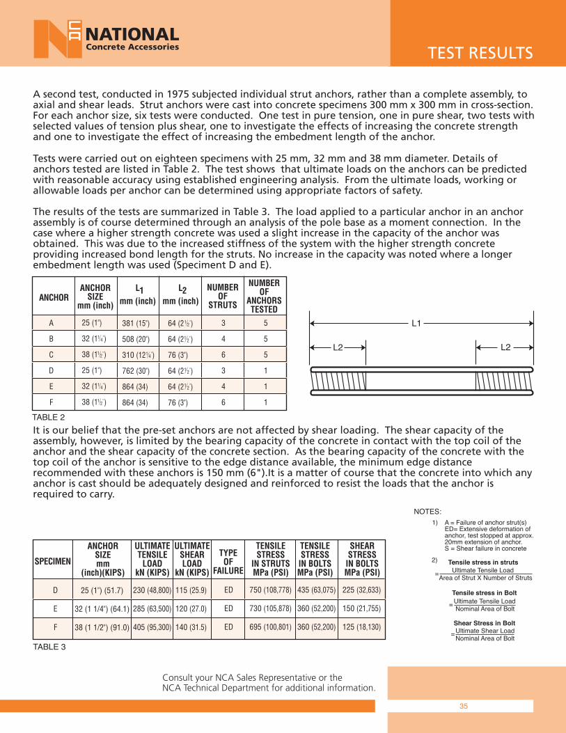
A second test, conducted in 1975 subjected individual strut anchors, rather than a complete assembly, to axial and shear leads. Strut anchors were cast into concrete specimens 300 mm x 300 mm in cross-section. For each anchor size, six tests were conducted. One test in pure tension, one in pure shear, two tests with selected values of tension plus shear, one to investigate the effects of increasing the concrete strength and one to investigate the effect of increasing the embedment length of the anchor.
Tests were carried out on eighteen specimens with 25 mm, 32 mm and 38 mm diameter. Details of anchors tested are listed in Table 2. The test shows that ultimate loads on the anchors can be predictedwith reasonable accuracy using established engineering analysis. From the ultimate loads, working or allowable loads per anchor can be determined using appropriate factors of safety.
The results of the tests are summarized in Table 3. The load applied to a particular anchor in an anchorassembly is of course determined through an analysis of the pole base as a moment connection. In thecase where a higher strength concrete was used a slight increase in the capacity of the anchor was obtained. This was due to the increased stiffness of the system with the higher strength concrete providing increased bond length for the struts. No increase in the capacity was noted where a longer embedment length was used (Speciment D and E).
It is our belief that the pre-set anchors are not affected by shear loading. The shear capacity of the assembly, however, is limited by the bearing capacity of the concrete in contact with the top coil of the anchor and the shear capacity of the concrete section. As the bearing capacity of the concrete with the top coil of the anchor is sensitive to the edge distance available, the minimum edge distance recommended with these anchors is 150 mm (6").It is a matter of course that the concrete into which anyanchor is cast should be adequately designed and reinforced to resist the loads that the anchor is required to carry.
TEST RESULTS
1) A = Failure of anchor strut(s) ED= Extensive deformation of anchor, test stopped at approx. 20mm extension of anchor. S = Shear failure in concrete
Ultimate Tensile Load Area of Strut X Number of Struts Ultimate Tensile Load Nominal Area of Bolt Ultimate Shear Load Nominal Area of Bolt
TABLE 2
TABLE 3
L2 L2
L1
ANCHORANCHOR
SIZEmm (inch)
L
mm (inch)1 L
mm (inch)2
NUMBEROF
ANCHORSTESTED
NUMBEROF
STRUTS
A
B
C
D
E
F
381 (15")
508 (20")
310 (12 )
762 (30")
864 (34)
864 (34)
25 (1")
32 (1 )
38 (1 )
25 (1")
32 (1 )
38 (1 )
64 (2 )
64 (2 )
76 (3")
64 (2 )
64 (2 )
76 (3")
3
4
6
3
4
6
5
5
5
1
1
1
1 4 "
1 4 "
1 4 "
1 2 "
1 2 "
1 2 "
1 2 "
1 2 "
1 2 "
SPECIMEN
ANCHORSIZEmm
(inch)(KIPS)
ULTIMATETENSILE
LOADkN (KIPS)
ULTIMATESHEARLOAD
kN (KIPS)
TENSILESTRESS
IN STRUTSMPa (PSI)
TENSILESTRESS
IN BOLTSMPa (PSI)
SHEARSTRESS
IN BOLTSMPa (PSI)
TYPEOF
FAILURE
D
E
F
230 (48,800)
285 (63,500)
405 (95,300)
25 (1") (51.7)
32 (1 1/4") (64.1)
38 (1 1/2") (91.0)
115 (25.9)
120 (27.0)
140 (31.5)
ED
ED
ED
750 (108,778)
730 (105,878)
695 (100,801)
435 (63,075)
360 (52,200)
360 (52,200)
225 (32,633)
150 (21,755)
125 (18,130)
Consult your NCA Sales Representative or theNCA Technical Department for additional information.
NOTES:
Tensile stress in struts=
Tensile stress in Bolt=
=Shear Stress in Bolt
2)
36
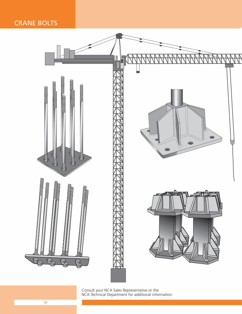
CRANE BOLTS
Consult your NCA Sales Representative or theNCA Technical Department for additional information.

37
CRANE BOLTS
Consult your NCA Sales Representative or theNCA Technical Department for additional information.
STANDARD GRADE (Yellow - For Summer) All crane anchor bolts supplied shall conform to CAN/CSA-G4021-98
Suitable for all standard crane application
Minimum yield strength of 44,000 psi
All crane anchor bolts shall be 8 Threads Per Inch
Nuts to be 2H heavy hex 8 Threads Per Inch (TPI)
Mill certificate to accompany shipment upon request
COLD WEATHER GRADE (Black - For Winter) All crane anchor bolts supplied as Cold Weather Grade shall have aminimum Charpy value of 15 ft.lb. @ -20∞F/(-28∞C)
Recommended and meets specification for applications where v-notch toughness at low temperature is a design requirement
Minimum yield strength of 60,000 psi
All crane anchor bolts shall be 8 Threads Per Inch
Nuts to be 2H heavy hex 8 Threads Per Inch (TPI)
Mill certificate to accompany shipment upon request
Other sizes available on request
DIAMETER LENGTH L1 L2
1 1/2"(38mm)
48"(1219mm)
8"(203mm)
14"(356mm)
1 1/2"(38mm)
40"(1016mm)
8"(203mm)
8"(203mm)
1 3/4"(45mm)
48"(1219mm)
8"(203mm)
14"(356mm)
1 3/4"(45mm)
40"(1016mm)
8"(203mm)
8"(203mm)
LEN
GTH
L2L1

38
ANCHOR BOLT
Consult your NCA Sales Representative or theNCA Technical Department for additional information.
NCA can manufacture a wide variety of Anchor Bolts to suite individual custom requirement. Anchor Bolts can be supplied in various material grades and diameters, supplied as black, coated, and hot dipped galvanized. Alternative steel grades available including grade 400,ASTM 615-grade 75, ASTM A722-150Ksi, B-7, Stainless etc.
NCA Crimped Anchors are used for form anchoring in massconcrete construction. Manufactured in the diameter and lengths shown with either national coarse thread or lag thread.
Anchor Bolt
Crimped Anchor
She-Bolt
BatterWasher
ThreadedInside Rod
Rod Coupling
DummyShe-Bolt
SettingBracket
CrimpedAnchor
CrimpedAnchor
Wing Nut
1500 mm (5'-0")
approximately 10˚
EXAMPLEName .................... Crimped AnchorDiameter .................... 13 mm (1/2")Length ....................... 30 mm (12")Type of thread ......................... NC Quantity ............................... 200
To order, please specifythe following information
Diameter Safe Working Load Ultimate
13 mm (1/2") 40 kN (9,000 lbs) 80 kN (18,000 lbs)
20 mm (3/4") 80 kN (18,000 lbs) 160 kN (36,000 lbs)
25 mm (1") 165 kN (37,500 lbs) 330 kN (75,000 lbs)
Crimped Anchor Safe Working Loads

39
ANCHOR BOLT
Consult your NCA Sales Representative or theNCA Technical Department for additional information.
EXAMPLEName .................. Hook Anchor BoltDiameter ...................... 25 mm (1")Quantity ............................... 200
To order, please specifythe following information
EXAMPLEName .................. Wall Plate AnchorDiameter .................... 13 mm (1/2")Length ....................... 200 mm (8")Thread ................................ UNCType of Steel ............. mild black steel Quantity ............................... 200
To order, please specifythe following information
The NCA Hook Anchor Bolt is manufactured with either lag thread or national course threads and is typically supplied with a 90∞ radius. NCA can supply custom bent bolts when provided with detailed specifications and drawings. Available in 13mm, 20mm, 25mm and 32mm (1/2", 3/4", 1", 1 1/4") diameter.
NCA Wall Plate Anchors are manufactured with Unified NationalCoarse (UNC) thread and are supplied complete with a nut andwasher. NCA can accommodate special orders in black, plated,hot dipped galvanized or stainless steel. Available in 10mm to 50mm (3/8" to 1/2") diameters. Custom orders available on request.
Hook Anchor Bolt
Wall Plate Anchor

40
THREADED RODS
Consult your NCA Sales Representative or theNCA Technical Department for additional information.
NCA All Thread Bars conform to ASTM A722 and ACI 318. The deformation complies with ASTM A615.
All Thread Bars are available in grade 60, 75, 95, and 150 to satisfy requirement for tyback, reinforcing connections and rock bolting.
All Thread Bars can be supplied as plain, hot dipped galvanized or epoxy coated.
Consult the NCA Technical Department for available bar diameters.
All Thread Bar
NCA Corrosion Protection Products
NCA provides a wide range of corrosion protection systems and sealants. They include hot dip galvanizing, coatings, rust inhibitor lubricants/grease,sealants, profiling mastics and tapes. Consult the NCA Technical Department for application recommendation and details.

41
Through Wall Ty Bar
Consult your NCA Sales Representative or theNCA Technical Department for additional information.
Square Nut ARSN
Hard Washer ARHRW
Bearing Plate ARBPH95 mm x 95 mm x 6 mm
All Thread Rod or Threadedas Required 5/8" left or RightHand Thread
F.J. Anchor Shell F3FL
Drill Hole1 1/4" Diameter
PlateWasher
Heavy 2HHex Nutand Washer
Thread Lengthas Required
Walers Stop Coupling
Temporary or PermanentWall Tie
Fill
Through Wall Ty Bar
All NCA bar products listed in NCA Rock Anchoring and Bolt Systemspublication can be considered for Through Wall Ty applications. NCA Standard Deform Bar (SDR) Continuous Threaded Lag (SCT-L) and our SolidSmooth Threaded (SST) products provide a wide range of economical solutions for tie back requirements. Refer to SDR, SCT-L or SST for material selection.
NCA engineered approach provides an innovative method to achievethe full working load requirement.
When design loads exceed published values, consult the NCA Technical Department.
Mesh Pin (ARMP)
The NCA Mesh Pin (ARMP) is typically supplied as a (5/8") fully threaded left hand assembly consisting of a heavy square nut, round flat washer, a small bearing plate and a F3FL anchor assembly. The NCA Mesh Pin was developed to be used to hold wire, chain link, or fencing type materials in place against a rock or concrete surface prior to shotcrete. The NCA Mesh Pincan also be supplied with right hand thread typically in lengths are 500, 600, 1000 or 1500mm (19", 23", 39” or 59”). Larger diameters and length are available if required. Please contact NCA for additional information.

Go to our web site at www.nca.ca for catalogue downloads & updates.
PRINTED IN CANADA CAS0713/2M/2.95
• Innovation and quality products• Technical support and design assistance• Superior customer service and satisfaction• A safe and positive work environment• Standard and custom made products to improve customer profitability
National Concrete Accessories provides over 35 years of experience in onsite solutions and is one of North America's leading manufacturers and distributors of concrete form hardware, accessories and construction products. National Concrete Accessories is part of a global organization committed to:
1-888-777-9272
VICTORIA602 John StreetVictoria, BC V8T 1T9Phone: (250) 388-4257Fax: (250) 383-5754
PRINCE GEORGE101-2050 Robertson RoadPrince George, BC V2N 1X6Phone: (250) 614-1212Fax: (250) 614-1140
BURNABY7885 Venture StreetBurnaby, BC V5A 1V1 Phone: (604) 435-6700Fax: (604) 435-6701
KAMLOOPS 855 Laval CrescentKamloops, BC V2C 5P2Phone: (250) 374-6295Fax: (250) 372-1586
KELOWNA 1948 Dayton StreetKelowna, BC V1Y 7W6Phone: (250) 717-1616Fax: (250) 717-1617
EDMONTON14305 - 128th AvenueEdmonton, AB T5L 3H3Phone: (780) 451-1212Fax: (780) 455-0827
RED DEER#5, 7803 - 50th AvenueRed Deer, AB T5L 3H3Phone: (403) 342-0210Fax: (403) 341-3245
CALGARY3834 - 54th Avenue S.E.Calgary, AB T2C 2K9Phone: (403) 279-7089Fax: (403) 279-4397
SASKATOON 419 - 50th Street EastSaskatoon, SK S7K 6K1Phone: (306) 242-3831Fax: (306) 242-9644
REGINA 495 Henderson DriveRegina, SK S4N 5X1Phone: (306) 525-1212Fax: (306) 525-1512
WINNIPEG 975 Marion StreetWinnipeg, MB R3J 3W8Phone: (204) 233-4107Fax: (204) 233-1474
TORONTO172 Bethridge RoadToronto, ON M9W 1N3Phone: (416) 245-4720Fax: (416) 242-2727
OTTAWA 1310 Leeds AvenueOttawa, ON K1B 3W3Phone: (613) 736-5050Fax: (613) 736-1271
MONTREAL 2111-B Léonard-de-VinciSainte-Julie, QuébecJ3E 1Z2Phone: (514) 327-9333Fax: (514) 324-6950