specification for pneumatic concrete breakers …bis.org.in/sf/med/me-18_1194-1349.pdf · ·...
TRANSCRIPT

Doc: MED 18(1194)c
1
For Comments Only
Draft Indian Standard
SPECIFICATION FOR PNEUMATIC CONCRETE BREAKERS
(First Revision of IS 3559)
___________________________________________________________________________
Not to be reproduced without the permission of Last date for receipt of
BIS or used as a STANDARD comments is: 30 Aug 2014
___________________________________________________________________________
NATIONAL FOREWORD
. (Formal clauses will be added later on).
0.1 Hand-held Pneumatic Concrete breakers have a wide variety of uses in general
construction, demolition work and in industrial plants. Breaker of heavy class are used for
breaking concrete pavements, demolition of concrete foundation and walls, cutting
pavements and sub-bases, trenching in hard ground and for breaking boulders which cannot
be otherwise blasted. Breakers of medium class are suitable for breaking light concrete
pavements and floors, macadam, frozen ground and gravel. Breakers of light class are useful
in light demolition work on floors, pavements and masonry walls. Light breakers are
particularly suitable for jobs requiring the operator to handle the tool continuously and for
work which is required to be carried out close to existing structures. This standard has been
prepared with a view to providing guidance to manufacturers and users in obtaining concrete
pneumatic breakers capable of giving satisfactory performance.
0.2 Heavy class breakers can be converted into sheeting drivers, heavy and medium breakers
can also be converted in to railway spike drivers by substituting a spike-driver head in place
of the regular front head.
0.3 Moil points can be substituted by various other breaking tools, such as narrow and wide
chisels, digging blades, frost wedges, asphalt cutters, clay spades and scoops, tamping pads,
and pipe or sheeting driver heads.
0.4 The dimensions of tool shanks for pneumatic concrete breakers have been specified on
the basis of current manufacturing practices in the country. Standards on shanks for all
pneumatic tools are, however under preparation and it is proposed to review the dimensions
specified in this standard when a separate standard on the subject becomes available.
0.5 This standard contains clause 5.4 which permits the purchaser to use his option for
selection to suit his requirement and clauses 10.1.2 and 10.1.3 which call for agreement
between the purchaser and the supplier.
0.6 In the formulation of this standard due weightage has been given to international co-
ordination among the standards and practices prevailing in different countries in addition to
relating it to the practices in this field in this country.

Doc: MED 18(1194)c
2
0.7 For this purpose of deciding whether a particular requirement of this standard is complied
with, the final value, observed or calculated expressing the result of a test or analysis, shall
be rounded off in accordance with IS 2:1960. The number of significant places retained in the
rounded off value should be the same as that of the specified value in this standard.
1 SCOPE
This standard lays down the requirements for sizes, dimensions and performances of concrete
pneumatic breakers.
2 REFERENCES
The standards given in Annex A contain provisions, which through reference in this text,
constitute provisions of this standard. At the time of publication, the editions indicted were
valid. All standards are subject to revision and parties to agreements based on this standard
are encouraged to investigate the possibility of applying the most recent editions of the
standards indicated in Annex A.
3 TERMINOLOGY
For the purpose of this standard, the following definitions shall apply.
3.1 Concrete Breaker - A heavy or medium weight percussive tool used for demolition
work.
3.2 Percussive Tool - A tool in which the piston reciprocates in a cylinder and gives a blow
at one end of its stroke.
3.3 Pneumatic Hand Tools - Any percussive and /or rotary tool.
3.4 Inserted Tool - Tool inserted in the non-rotary percussive power tool to perform the
intended work.
3.5 Service Tool - Tool intended for performing maintenance or service on the non-rotary
percussive power tool
3.6, Control Device - Device to start and stop the non-rotary percussive power tool or to
change the direction of the rotation or to control the functional characteristics such as speed
and power.
3.7 Start And Stop Device Throttle - A manually operated control on the non-rotary
percussive power tool by which the energy supply to the motor can be turned on and off.
3.8 Hold To Run Start And Stop Device Constant Pressure Throttle - A start and stop
device which automatically returns to the “OFF” position when force on the start and stop
device actuator is released.

Doc: MED 18(1194)c
3
3.9 Lock-On Start And Stop Device Constant Pressure Throttle With Instant Release
Lock - A hold to run start and stop device which can be locked in the on position and
designed so that it permits the non-rotary percussive power tool to be turned off by a single
motion of the same finger or fingers used to turn it on.
3.10 Lock-Off Start And Stop Device Lock-Off Throttle - A start and stop device that
automatically latches in the off position when the actuator is released and where two motions
are required to energize the non-rotary percussive power tool.
3.11 Positive On-Off Start And Stop Device Positive On-Off Throttle - A start and stop
device that remains in an on position until it is manually changed.
3.12 Maximum Operating Pressure - Maximum pressure that a non-rotary percussive
power tool may be operated at.
3.13 Whip Hose - Air hose, connected between the main air hose and an air tool for the
purpose of providing more flexibility.
3.14 Rated Air Pressure - Air pressure, required at an air tool inlet port to assure rated
performance of the tool, also considered the maximum pressure at which the tool may be
operated.
3.15 Rated Speed - The speed, in revolutions per minute, of an air tool at no load and rated
air pressure at the tool inlet port.
.
3.16 Maximum Attainable Speed - The maximum speed which the tool can achieve under
the most adverse condition of possible miss adjustment or malfunction of its speed control
devices, when supplied with compressed air at the pressure marked on the non-rotary
percussive power tool.
3.17 Suspension device - A device attached to the tool whose primary purpose is to reduce
the strain on the operator caused by the weight of the tool.
NOTE - The device may also have a secondary purpose of transmitting a reaction torque
3.18 Non Rotary Percussive Power Tool - Power tool which delivers a series of percussive
blows, without rotary action of the inserted tool.
3.19 Sound Power (W) - The rate per unit times at which air borne sound energy is radiated
by a source. It is expressed in Watts.
3.20 Sound Power Level (Lw) - Ten times the logarithm to the base of ten of the ratio of
the sound power radiated by a source under test to the reference sound power. It is expressed
in decibels.
The frequency weighting or the width of the frequency band used shall be indicated. The
reference power is 1 pW( 1 pW = 10 -12
W)

Doc: MED 18(1194)c
4
3.21. Routine Tests - Test carried out on each pneumatic breaker to verify conformity to the
performance requirements laid down in this standard.
3.22 Type Tests - Tests carried out on a type pneumatic breaker to verify conformity to the
performance requirements laid down in this standard.
4 MATERIALS
All materials used in the construction of pneumatic concrete breakers shall conform to the
requirement relevant Indian Standards.
5 SIZES
Pneumatic concrete breakers shall be classified according to their weight as under:
a) Light Up to 20kg.
b) Medium Over 20 kg and up to 32 kg
c) Heavy Over 32 kg and up to 40 kg.
NOTE - All weights shall be of the basic tool without any attachments or accessory.
6 CONSTRUCTION
6.1 General
The breaker shall consist of a back head equipped with a handle, a cylinder assembly, and a
throttle: and a front head equipped with a chuck for the collar shanked tools of dimensions
given in Fig 1. Unless otherwise specified, the handle shall be a “T” handle.

Doc: MED 18(1194)c
5
FIG 1
DIMENSIONS OF TOOL SHANKS FOR PNEUMATIC CONCRETE BREAKER.
6.2 Back Head assembly
The back head assembly shall consist of a housing of forged steel or any other equally
suitable material, a “T”- handle and a throttle lever. The throttle lever shall be located to
permit operation of the breaker from either side.
6.2.1 Cylinder Assembly
The cylinder assembly shall consist of a forged steel or any other equally suitable material,
a valve mechanism to control the direction of air required for actuation of the piston, an
anvil block sleeve and a reversible piston.
6.2.2 Flanges
All flanges shall have sufficient thickness and strength to prevent failure during operation
and to withstand mechanical stress when back head and front head assemblies are installed.
6.3 The front head assembly shall consist of a chuck housing of forged steel or any other
equally suitable material, a chuck for collar shank tool of dimensions given in Fig.1 and a
positive shank retaining device, such as latch retainer or swing stirrup type spring retainer.
The chuck housing of the breaker shall contain a renewable liner or shall be of solid type.
6.4 Air Inlet Connection

Doc: MED 18(1194)c
6
The air inlet connection shall permit operation of the breaker without any obstruction to the
normal working or any restraint on the operator. If so required by the purchase, swivel type
air inlet connection may be provided. The end of the air inlet connection shall have an
extended thread and shall be provided with a nipple suitable for connection to 20 mm air
hose.
6.5 Exhaust Port
The exhaust port shall be located to direct exhaust air downward and away from the operator
when the breaker is operated from either side.
6.6 Air Cushion
The cylinder shall have a suitable air cushion at both ends of the piston stroke.
6.7 Lubrication
All surfaces requiring lubrication shall be provided with means for lubrication through the
use of either an internal oil reservoir or an air line oiler. When an oil reservoir is furnished,
it shall have a capacity of not less than 4 h of continuous operation while operating at
6.5 kg/cm2 gauge pressure at the tool.
7 WORKMANSHIP
The breaker shall be free from defects resulting from contact of dissimilar metals, rust,
cracks, incomplete welds and other defects that could impair its operation or serviceability.
All parts, components, and assemblies including castings, forgings, moulded parts,
stampings, bearings, seals, machined surfaces and welded parts shall be cleaned free of sand,
dirt, fins, pits, sprues, scales, flux and other harmful or extraneous materials. External
surfaces shall be smooth and all edges shall be rounded or beveled.
8 SAFETY REQUIREMENTS
8.1 The breaker shall be provided with a positive lock which will prevent the accessory
from becoming accidentally disengaged from the breaker. It shall be fitted with vibration
resisting equipment and shall be so designed that the vibrations and recoil under working
conditions are with in the limits specified in relevant safety regulations.
8.2 Mechanical Safety
8.2.1 Surfaces, Edges and Corners
Accessible parts of non-rotary percussive power tools, except the inserted tool, shall not have
sharp edges or angles or rough or abrasive surfaces, see ISO 12100-2:2003, 4.2.1.

Doc: MED 18(1194)c
7
8.2.2 Supporting Surface and Stability
The non-rotary percussive power tool shall be so designed that it can be laid aside and remain
in stable position on a plane surface.
8.2.3 Ejection of Parts
A retainer shall be integral with or installed on a non-rotary percussive power tool which,
without such a retainer, can eject the inserted tool when it is operated off a work surface.
8.2.4 Power Tool Construction
The non-rotary/rotary percussive power tool shall be so designed and constructed as to
prevent the loosening or loss of components during expected use, including rough handling
and occasional dropping, which can cause its safety functions to be compromised.
8.3 Noise
The non-rotary and rotary percussive power tool shall be designed and constructed so that the
emission of noise is reduced to the lowest level, taking account of technical progress and the
availability of means of reducing noise, in particular at source.
The noise emission from using non-rotary percussive power tools has three main sources:
a) The non-rotary / Rotary percussive power tool itself,
b) The inserted tool, and
c) The work piece.
NOTE 1 - Generally the noise emitted due to the characteristics of the work piece cannot be controlled directly by
the manufacturer of the non-rotary percussive power tool.
Typical sources of noise emitted by the non-rotary percussive power tool itself are:
a) The motor and drive mechanism,
b) The exhaust air or gases, and
c) Vibration or impact-induced noise.

Doc: MED 18(1194)c
8
Where the exhaust air or gases are the major contributor to the noise, means to reduce the
noise, for example a silencer or equivalent means, shall be included in the design.
NOTE 2 - Alternatively, the exhaust air or gases can be piped away in a hose, away from the operator, where this is
practicable.
Vibration-induced noise can often be reduced by vibration isolation and damping.
This list is not exhaustive; where alternative technical measures for noise reduction, with
greater efficiency, are available, they should be used by the manufacturer
8.4 Vibration
The non-rotary / Rotary percussive power tool shall be designed and constructed so that the
vibration is reduced to the lowest level at the handles, and at any other parts of the tool in
contact with the operator’s hands, taking account of technical progress and the availability of
means of reducing vibration, in particular at source.
Typical sources of vibration emitted by a non-rotary percussive power tool are:
a) Impacts,
b) Poorly designed motors, and
c) Resonances in the structure of the machine, particularly the handles and
their mounts.
The following design features have been found to be effective and should be considered by
manufacturers when designing non-rotary percussive power tool:
a) Reaction masses and springs, b) Increasing inertia, and
c) Isolated casing or handles.
This list is not exhaustive; where alternative technical measures for vibration reduction, with
greater efficiency, are available, they should be used by the manufacturer.
8.5 Lubrication
When specifying lubricants the manufacturer shall take environmental and occupational
health aspects in to account.
8.6 Ergonomics
8.6.1 Design of the Handle
Gripping areas of the non-rotary / Rotary percussive power tools shall be designed to
provide convenient, effective means for the operator to exercise full control over the non-
rotary percussive power tool.

Doc: MED 18(1194)c
9
Handles and other parts used for gripping the non-rotary percussive power tool shall be
designed to ensure that the operator is able to grip the non-rotary percussive power tool
correctly and to perform the expected work. Handles shall suit the functional anatomy of the
hand and the dimensions of the hands of the operator population.
Non-rotary percussive power tools having a mass greater than 2 kg (including the inserted
tool) shall be capable of being supported by two hands whilst being lifted or operated.
The grip shall be such that normal feed force can be transmitted in an ergonomic way from
the hand of the operator to the non-rotary percussive power tool.
8.7 Controls
8.7.1 Start and Stop Device
It shall be adapted to the handle, or to the part of the non-rotary percussive / Rotary power
tool being gripped, so that it can be held comfortably in the run position, and so that the
operator can activate it without releasing the grip on the handles.
Start and stop devices shall be so designed that the inserted tool ceases to be powered when
the start and stop device is released. Without manual effort it shall, when completely
released, move to the stop position, that is be of the type "hold to run".
Start and stop devices shall be in the stop position or immediately move to the stop position
when the assembly non-rotary percussive power tool for threaded fasteners is connected to
the energy supply.
It shall not be possible to lock the start and stop device in the running position.
8.7.2 Unintentional Start
The start and stop device shall be so designed, positioned or guarded that the risk of
unintentional start is minimized. Verification shall be made according to clause 8.4.
9 PERFORMANCE CHARCTERISTICS.
9.1 General Conditions for Tests
9.2 Noise
The noise emission values shall be measured and reported in accordance with ISO 15744.
The noise emission values and their uncertainties shall be declared in accordance with
ISO 4871.
Compliance with 7.3 may be verified through the comparison of the noise emission values
with those for other machines of the same family, of similar size and performance
characteristics.

Doc: MED 18(1194)c
10
9.3 Vibration
The vibration total value for non-rotary percussive power tools shall be measured and
reported in accordance with ISO 28927-6, ISO 28927-9 and ISO 28927-10.
The vibration emission value and its uncertainty shall be declared in accordance with
EN 12096.
Compliance with 7.4 may be verified through the comparison of the vibration emission
values with those for other machines of the same family, of similar size and performance
characteristics.
9.4 Unintentional Start
Compliance with 7.7.2 shall be verified for non-rotary percussive power tools up to
15 kg as follows:
a) The retainer shall be mounted and not removed.
b) The non-rotary percussive power tool shall be connected to the energy
supply and be placed in any possible position and pulled over a horizontal
plane by its hose.
c) Operation of the start and stop device shall then not occur.
9.5 Power Tool Construction
Except for breakers, compliance with 7.2.4 shall be verified by dropping a sample non-rotary
percussive power tool three times onto a concrete surface from a height of 1 m without
affecting its operational and safety functions. The sample shall be positioned to vary the
point of impact.
9.6 The breaker shall be operable in any position. Performance characteristics of the breaker,
when tested in accordance with 8.7 to 8.11 shall conform to the requirement given in Table 1.
9.7 Operational Test
The breaker shall be operated with 5 to 7 kg/cm2 gauge pressure at the tool for not less than
100 h for breaking cement concrete. Inability of the breaker to complete this test, or the
presence of any of the following defects during operation shall continue failure of this test:
a) Accessory accidentally disengages from the breaker;
b) Absence of oil vapor in the exhaust air;
c) Air supply hose interferes with operator when breaker is operated in all possible
positions;
d) Evidence of damage to, or permanent deformation or breakage of any component
or part;

Doc: MED 18(1194)c
11
e) Exhaust air is not directed down word and away from the operator; and
f) Oil reservoir, when furnished, has less than 25 minutes continuous operational
capacity at6.5 kg/cm2
gauge air pressure at the tool.
9.7.1 When furnished, the spike driver and sheeting driver shall be operated for not les than
10 h each. The spike driver shall drive railroad spikes and the sheeting driver shall drive
planks for 50 mm and 75 mm thickness. Failure of the breaker to convert to and operate as a
spike driver and a sheeting driver shall constitute failure of this teat.

Doc: MED 18(1194)c
12
9.8 Air Consumption Test
The water displacement meter or any other equally suitable instrument shall be used to
determine the quality of air consumed per minute at 6.5 kg/cm2 gauge pressure on the tool.
Air consumption in excess of that specified in Table 1 shall constitute failure of the breaker
in this test.
9.9 Force of Blow ( Pellet Test)
9.9.1 The force of blow of the breaker shall be measured by pellet test. This consists in
operating the breaker for a specified period to beat down a cylindrical test piece ( pellet) of
steel of known tensile strength and machined to close limits, and measuring the reduction in
length of the pellet.
9.9.2 The test gear shall consist of a firm solid steel base up on which a removable
substantial pot with hardened steel bush and having a vertical opening of 32 mm diameter is
mounted with dowels. Typical details of a suitable solid base are given in Fig.2 through any
other suitable firm and solid base may be used by agreement between the purchaser and the
supplier.
9.9.3 The breaker shall be fitted with blank steel plunger 30 mm in diameter, approximately
2.15kg in weight and hardened to RC-55 throughout. The shank dimensions of the plunger
shall conform to Fig 1.
9.9.3.1 The cylindrical test piece (Pellet) of mild steel of 44-55 kg/mm2. tensile strength and
hardness RB85-90, and of dimensions indicated below shall be vertically placed in position
in the pot of the impact testing machine.
Sl. No. Breaker Pellet
Dia Length
mm mm
+0.50
i) Light 14.3 0.05 14.3
ii) Medium 25.4 25.4
iii) Heavy 25.4 25.4
The breaker shall be placed in position so that the blank steel plunger rests on the upper end
of the pellet. The breaker shall then be operated in hand held position for 5

Doc: MED 18(1194)c
13
seconds(measured with stop watch) at 6.5 kg/cm2 gauge air pressure. The breaker and the
plunger shall then be released and the pellet withdrawn from the pot.

Doc: MED 18(1194)c
14
9.9.3.2 The comparison (reduction in length ) of the pellet shall be measured by means of a
micrometer and reported.
FIG 2
TYPICAL DETAILS OF SOLID BASE FOR PELLET TEST
9.10 Sound Power Level Determination.
The acoustic environment, instrumentation, quantities to be measured and
determined, and measurement procedure shall be as specified in ISO 3744:1994.
The sound power level shall be given as an A-weighted sound power level in decibels, with
a reference of 1 pW. The A-weighted sound pressure levels, from which the sound power is
to be determined, should be measured directly, and not calculated from frequency band data.
9.11 Vibration
The instructions must give the following information concerning vibrations
transmitted by hand-held and hand-guided machinery:
The weighted root mean square acceleration value to which the arms are subjected, if it
exceeds 2.5 m/s2 as determined by the appropriate test code. Where the acceleration does not
exceed 2.5 m/s2, this must be mentioned.

Doc: MED 18(1194)c
15
If there is no applicable test code, the manufacturer must indicate the measurement methods
and conditions under which measurements were made
10 TESTS
10.1 Type Tests

Doc: MED 18(1194)c
16
The following shall constitute type test:
a) Operational test as per 8.7;
b) Sound power level test;
c) Rotation torque test, if the tool has got rotation;
d) Force of blow ( pellet test ); and
e) Vibration test.
10.2 Routine Tests
The following constitute the routine teats, which must be conducted in all the tools
manufactured. The tool must run for about 10 min to stabilise.
a) Air consumption test as per 8.9;
b) Piston speed test; and
b) Drill steel speed no load (RPM) test, if the tool has got rotation
-
10.3 If so specified, when inviting tender, tests shall be carried out at the manufacturer’s
works in the presence of purchaser or his representative to ensure that the breaker conforms
to the requirements of this standard and complies with routine tests indicated in 9.1. In the
case when a batch of 30 or more similar breakers is supplied to one order, type tests as
specified, shall be made on one of these breakers, if the purchase so requires.
10.4 Test Certificates
10.4.1 Unless otherwise specified when inviting tender, the purchaser, if so desired by the
manufacturer, shall accept as evidence of the compliance of the breaker with the
requirements of, tests on a breaker identical in essential details with one purchased, together
with routine test on each individual breaker.
10.4.2 Certificate of routine tests shall show the breaker purchased has been run and has been
found to be sound in working order in all respects as specified in this standard.
10.4.3 Certificates showing records of all type tests carried out on the breaker, shall be kept
at available by the manufacturer for inspection.
11 ACCESSORIES AND ATTACHMENTS.
11.1 Accessories
When so specified by the purchaser, the following accessories shall be supplied with the
breaker.
a) Chisel ;
b) Moil point ;
c) Tamping pad;
d) Tamping rod;

Doc: MED 18(1194)c
17
e) Air line oiler; and
f) Silencer.
11.1.1 Chisel and Moil Point
The chisel and moil point shall be made of forged steel or any other equivalent material.
They shall be supplied as normalized hardened and tempered to hardness of minimum RC55
through out its length so that the hardness may be subsequently improved by user as per his
requirements.
11.1.1.1 Dimensions
Unless otherwise agreed to between the purchaser and the supplier, the chisel and moil point
shall have a length of 350 ± 12.5 mm exclusive of the shank and collar and the chisel shall
have a cutting edge width of 75 ± 3 mm.
11.1.2 Tamping Rod
The tamping rod shall be made of forged steel conforming to relevant Indian Standards and
shall be of a suitable shape as agreed between the purchaser and supplier( see note under
10.1.3).
11.1.3 Tamping Pad
The tamping pad shall be of cast steel and shall be of a suitable shape agreed between the
purchaser and the supplier (see Note) . The weight of the tamping pad shall not be less than
6 kg.
NOTE - Suitable shapes of tamping rod and tamping pad generally in common use are given in Fig. 3.
11.2 Attachments
When so specified by the purchaser the following attachments shall be furnished with the
breaker:
a) Spike driver; and
b) Sheeting driver.
11.2.1 Spike Driver
The medium and heavy breaker shall be convertible for use spike driver by replacement of
the standard front head with a front head constructed specifically for driving railroad spikes.
11.2.2 Sheeting Driver
The medium and heavy breaker shall be convertible for use as a sheeting driver by
replacement of the standard front head with a front head constructed specifically for driving

Doc: MED 18(1194)c
18
sheeting and planks. The sheeting driver shall be of forged steel and shall be adjustable for
driving 50 to 75 mm planks.
12 TOOLS
Maintenance and operating tools required for normal running adjustments and, lubrication
shall be provided with the pneumatic breaker along with necessary instructions.
13 PAINTING
All exposed parts shall be cleaned and given suitable anti-corrosive treatment and protection.
The body shall be painted as per the company’s standard or to the requirement of the
purchase.
14 MARKING
14.1 Each pneumatic breaker shall have the following information suitably marked on it:
a) Manufacturer’s Name and Trademark;
b) Pneumatic breaker reference / Model number;
c) Weight of the breaker;
d) Serial number of that tool;
e) The rated air pressure (max); and
f) Maximum air consumption.
14.2 Instruction Handbook
14.2.1 General
The information provided by the manufacturer is an important but not exclusive basis for safe
use of the non-rotary percussive /rotary power tool. It shall provide sufficient information for
the end user to perform an initial risk assessment.
The hazards identified in 13.2.2.4 to 13.2.2.11 are foreseeable in the general use of non-
rotary percussive power tools. The information provided with the non-rotary rotary
percussive power tool shall state that the user or the user’s employer should assess the specific risks that may be present as a result of each use.
The instruction handbook shall at least contain information relating to the following:
a) The name and address of the manufacturer or supplier or any other agent
responsible for placing the non-rotary percussive power tool on the
market;
b) The designation of the series or type;
c) Operating instructions, (see 13.3);
d) Information on noise émission, (see 13.4.2);

Doc: MED 18(1194)c
19
e) Information on vibration transmitted to the hands of the operator,
(see 13.4.3);
f) Maintenance instructions, (see 13.5); and
g) Information about residual risks and how to control them.
14.2.2 Operator's Instructions
14.2.2.1 Statement of use
The operator's instruction shall include a description of the correct use of the non-rotary
percussive power tool and make reference to the appropriate inserted tools. The operator's
instruction shall state that any other use is forbidden. Foreseeable misuse of the non-rotary
percussive power tool, which experience has shown to occur, shall be warned against.
14.2.2.2 Allowance for user
The operator’s instruction shall be written primarily for professional users. Where a tool may
be used by non-professional users then additional information for use shall be provided.
14.2.2.3 General safety rules
Warnings shall be given with regards to significant hazards arising from or associated with
the use of the non-rotary percussive power tool.
The following is a non-exhaustive list. Manufacturers may add additional warnings:
a) Multiple hazards. Read and understand the safety instructions before
installing, operating, repairing, maintaining, changing accessories on, or
working near the non-rotary percussive power tool. Failure to do so can
result in serious bodily injury;
b) Only qualified and trained operators should install, adjust or use the
non-rotary percussive power tool;
c) Do not modify this non-rotary percussive power tool. Modifications may
reduce the effectiveness of safety measures and increase the risks to the
operator;
d) Do not discard the safety instructions – give them to the operator; and
e) Do not use the non-rotary percussive power tool if it has been damaged.
14.2.2.4 Projectile hazards
a) Disconnect the non-rotary percussive power tool from the energy source
when changing inserted tool or accessories;
b) Failure of the work piece, or accessories, or even of the inserted tool itself
may generate high velocity projectiles;
c) Always wear impact-resistant eye protection during operation of the non-
rotary percussive power tool. The grade of protection required should be
assessed for each use;
d) On overhead work, wear a safety helmet;
e) The risks to others should also be assessed at this time;

Doc: MED 18(1194)c
20
f) Ensure that the work piece is securely fixed;
g) Never operate a tool unless the inserted tool is retained in the tool with a
proper retainer;
h) To avoid injury, retainer parts must be replaced when they become worn,
cracked or distorted; and
j) Hold the inserted tool firmly against the work surface before starting the
tool.
14.2.2.5 Operating hazards
a) Use of the tool may expose the operator’s hands to hazards including impacts, cuts and abrasions and heat. Wear suitable gloves to protect
hands;
b) Operators and maintenance personnel must be physically able to handle
the bulk, weight and power of the tool;
c) Hold the tool correctly: be ready to counteract normal or sudden
movements – have both hands available;
d) Maintain a balanced body position and secure footing;
e) Release the start and stop device in the case of an interruption of the
energy supply;
f) Use only lubricants recommended by the manufacturer;
g) Avoid direct contact with the inserted tool during and after use as it will
become heated; and
h) Personal protective safety glasses shall be used, suitable gloves and
protective clothing are recommended.
14.2.2.6 Repetitive motions hazards
a) When using a non-rotary percussive power tool to perform work-related
activities, the operator may experience discomfort in the hands, arms,
shoulders, neck, or other parts of the body;
b) While using a non-rotary percussive power tool, the operator should adopt
a comfortable posture whilst maintaining secure footing and avoiding
awkward off-balanced postures. The operator should change posture
during extended tasks which may help avoid discomfort and fatigue; and
c) If the operator experiences symptoms such as persistent or recurring
discomfort, pain, throbbing, aching, tingling, numbness, burning
sensation, or stiffness, these warning signs should not be ignored. The
operator should tell the employer and consult a qualified health
professional.
14.2.2.7 Accessory hazards
a) Disconnect non-rotary percussive power tool from energy supply before
changing the inserted tool or accessory;
b) Only use sizes and types of accessories and consumables that are
recommended by the non-rotary percussive power tool manufacturer;

Doc: MED 18(1194)c
21
c) [for hammers, where appropriate] Never use any chisel as a hand struck
tool. They are specifically designed and heat-treated to be used only in
non-rotary percussive power tools;
d) [for hammers and breakers, where appropriate] Never use blunt chisels as
they require excessive pressure and can break from fatigue. Blunt tool-
pieces may increase vibration therefore sharp tools should always be used;
e) [for hammers, where appropriate] Never cool a hot accessory in water.
Brittleness and early failure can result;
f) [for hammers, where appropriate] Chisel breakage or tool damage may
result from misuse of using the tool as a lever that is, prising. Take smaller
bites to avoid getting stuck; and
g) Avoid direct contact with the inserted tool during and after use as it can be
hot or sharp.
14.2.2.8 Workplace hazards
a) Slips, trips and falls are major causes of workplace injury. Be aware of
slippery surfaces caused by use of the tool and also of trip hazards caused
by the air line;
b) Proceed with care in unfamiliar surroundings. Hidden hazards may exist,
such as electricity or other utility lines;
c) This non-rotary percussive power tool is not intended for use in potentially
explosive atmospheres and is not insulated from coming into contact with
electric power;
d) Make sure there are no electrical cables, gas pipes etc. that could cause a
hazard if damaged by use of the tool.
14.2.2.9 Dust and fume hazards
a) Dusts and fumes generated when using non-rotary percussive power tools
can cause ill health (for example: cancer, birth defects, asthma and/or
dermatitis); risk assessment of these hazards and implementation of
appropriate controls of is essential;
b) Risk assessment should include dust created by the use of the tool and the
potential for disturbing existing dust;
c) Operate and maintain the non-rotary percussive power tool as
recommended in these instructions, to minimise dust or fume emissions;
d) Direct the exhaust so as to minimise disturbance of dust in a dust filled
environment;
e) Where dusts or fumes are created, the priority shall be to control them at
the point of emission;
f) All integral features or accessories for the collection, extraction or
suppression of airborne dust or fumes should be correctly used and
maintained in accordance with the manufacturer’s instructions; g) Select, maintain and replace the consumable/inserted tool as
recommended in these instructions, to prevent an unnecessary increase in
dust or fumes; and

Doc: MED 18(1194)c
22
h) Use respiratory protection as instructed by your employer and as required
by occupational health and safety regulations.
14.2.2.10 Noise hazards
a) Unprotected exposure to high noise levels can cause permanent, disabling,
hearing loss and other problems such as tinnitus (ringing, buzzing,
whistling or humming in the ears);
b) Risk assessment of these hazards and implementation of appropriate
controls of is essential;
c) Appropriate controls to reduce the risk may include actions such as
damping materials to prevent work pieces from ‘ringing’; d) Use hearing protection as instructed by your employer and as required by
occupational health and safety regulations;
e) Operate and maintain the non-rotary percussive power tool as
recommended in these instructions, to prevent an unnecessary increase in
noise levels;
f) Select, maintain and replace the consumable/inserted tool as
recommended in these instructions, to prevent an unnecessary increase in
noise; and
g) If the non-rotary percussive power tool has a silencer, always ensure it is
in place and in good working order when the non-rotary percussive power
tool is operating.
14.2.2.11 Vibration hazards
The information for use must draw attention to vibration hazards that have not been
eliminated by design and construction and remain as residual vibration risk. It must enable
employers to identify the circumstances in which the operator is likely to be at risk from
vibration exposure. If the vibration emission value obtained using ISO 28927-6, ISO 28927-9
and ISO 28927-10 does not adequately represent the vibration emission in the intended uses
(and foreseeable misuses) of the machine, additional information and/or warnings shall be
supplied to enable the risks arising from vibration to be assessed and managed.
The following warnings (or equivalent) shall be given:
a) Exposure to vibration can cause disabling damage to the nerves and blood
supply of the hands and arms;
b) Wear warm clothing when working in cold conditions and keep your
hands warm and dry;
c) If you experience numbness, tingling, pain or whitening of the skin in your
fingers or hands, stop using the non-rotary percussive power tool, and tell
your employer and consult a physician;
d) Operate and maintain the non-rotary percussive power tool as
recommended in these instructions, to prevent an unnecessary increase in
vibration;
e) Do not hold the inserted tool with the free hand as this is will increase
vibration exposure;

Doc: MED 18(1194)c
23
f) Hold the tool with a light but safe grip taking account of the required hand
reaction forces, because the risk from vibration is generally greater when
the grip force is higher;
g) Keep suspended handles in the central position and avoid pushing the
handles into the end stops;
h) [for breakers] Cut small ‘bites’ of concrete to prevent the tool jamming
j) [for breakers] Move the cutting tool every few seconds. Stop the breaker
when lifting the tool to change position, because vibration is high when
pulling up on the handles.
14.2.3 Additional Safety Instructions for Pneumatic Power Tools
The following additional warnings (or equivalent) shall be given with all pneumatic non-
rotary percussive power tools:
a) Air under pressure can cause severe injury;
i) Always shut off air supply, drain hose of air pressure and
disconnect tool from air supply when not in use, before changing
accessories or when making repairs.
ii) Never direct air at yourself or anyone else.
b) Whipping hoses can cause severe injury. Always check for damaged or
loose hoses and fittings;
c) Cold air to be directed away from hands;
d) Do not use quick disconnect couplings at tool inlet. Use hardened steel (or
material with comparable shock resistance) threaded hose fittings.
e) Whenever universal twist couplings (claw couplings) are used, lock pins
must be installed and whip check safety cables shall be used to safeguard
against possible hose to tool and hose to hose connection failure;
f) Do not exceed the maximum air pressure stated on the tool; and
g) Never carry an air tool by the hose.
14.2.4 Specific Safety instructions
Warnings shall be given about any specific or unusual hazards associated with the use of the
non-rotary percussive power tool. Such warnings shall indicate the nature of the hazard, the
risk of injury and the avoidance action to take.
14.3 Operating Instructions
The instructions shall include, where appropriate:
a) Instructions for setting-up or fixing the non-rotary percussive power tool
in a stable position as appropriate for non-rotary percussive power tools
which can be mounted in a support;
b) Assembly instructions, including recommended guards, accessories and
inserted tools;
c) Illustrated description of functions;
d) Limitations on tool use by environmental conditions;

Doc: MED 18(1194)c
24
e) Instructions for setting and testing; and
f) General instructions for use, including changing inserted tools and limits
on the size and type of work piece.
14.4 Data
14.4.1 General
The instructions shall include the information on the data plate and the following:
a) Mass of the non-rotary percussive power tool.
14.4.2 Noise
14.4.2.1 Declaration of emission
The instructions shall include the noise emission values and uncertainties as specified in 8.2
and the reference number of the test code, ISO 15744.

Doc: MED 18(1194)c
25
14.4.2.2 Additional information
If the values for noise emissions obtained using the appropriate tests defined in clause 8.2 do
not adequately represent the emissions during the intended uses of the machine, additional
information and/or warnings shall be supplied to enable the risks arising to be assessed and
managed.
NOTE - Information on noise emission should also be provided in the sales literature.
14.4.3 Vibration
14.4.3.1 Declaration of emission
The instructions shall include the vibration emission value and uncertainty as specified in 8.3
and the reference number of the test code, ISO 28927-6, ISO 28927-9 or ISO 28927-10.
14.4.3.2 Additional information
If the values for vibration emissions obtained using the appropriate tests defined in clause8.3
do not adequately represent the emissions during the intended uses of the machine, additional
information and/or warnings shall be supplied to enable the risks arising to be assessed and
managed.
NOTE - Information on vibration emission should also be provided in the sales literature.
14.5 Maintenance Instructions
The maintenance instruction shall contain:
a) Instruction to keep the non-rotary percussive power tools safe by regular preventative
maintenance;
b) Information on when the regular preventative maintenance shall be carried
out, for instance after a specified time of operation, a specified number of
cycles/operations, a stated number of times per year;
c) Instructions for disposal so as not to impose hazards to personnel and the
environment;
d) A list of the service operations that the user should carry out;
e) Instructions for lubrication if required;
f) Instructions to check the speed and make a simple check of the vibration
level after each service;
g) Instructions to check the speed regularly; and
h) The specifications of the spare parts to be used, when these affect the
health and safety of operators.
Maintenance instructions shall include precautions to be taken to avoid exposure to
hazardous substances deposited (due to work processes) on the tool.
NOTE - Skin exposure to hazardous dusts may cause severe dermatitis. If dust is generated or disturbed during the
maintenance procedure it can be inhaled.

Doc: MED 18(1194)c
26
.
FIF, 3 TYPICAL DETAILS OF TAMPING ROD AND PAD.

Doc: ME 18 (1349)
June 2014
0
Draft Indian Standard PLANTS, TOOLS, AND EQUIPMENTS REQUIRED FOR CONSTRUCTION OF
CONCRETE ROADS AND OTHER CONCRETE STRUCTURES
ICS No: 91.080.40; 91.220; 93.080.10
Not to be reproduced without the permission of Last date for receipt of
BIS or used as a STANDARD comments is: 30 Aug 2014
.
FOREWORD
(Formal clauses will be added later on).
1.1 Even though greater mechanization of concrete pavement and other structures has a
lot to commend itself both from the point of quality and output of construction. in view of peculiar socio-economic infra-structure of our country most of construction in small projects, works for villages or for small towns, may be carried out with a minimum of mechanization for quite some time. In addition to small mechanized units, semi-mechanized construction requires a number of small, though none-the-less special, tools and equipments for various manual phases. Larger equipment like automatic concrete batching plants, trim plants are being manufactured commercially in our country, and for these standard specifications viz IS 4925 and IS: ….., exist to ensure their performance. There are now commercially available equipments such as floater, finisher, screed vibrators, needle vibrators of different dia like 20mm, 40 mm, and 60 mm, intelligent rollers etc used for construction of concrete roads and structures . Sometimes, these have also normally been got fabricated by the field engineer for the particular project. Large size fixed form and slip form pavers, are being used in India for heavy traffic roads. Fixed forms pavers are being manufactured in India; however, slip form pavers complete with automatic dowel bar inserter and tie bar inserter are not being manufactured in India at present.
1.2 In absence of any guidelines in respect of smaller tools and equipment, pavers, screed vibrators, new types of tools, the field engineers have been experiencing difficulties when executing concrete paving and other concrete structural jobs. It has, therefore, been felt necessary to provide some basis for the fabrication of such tools and equipment keeping with the performance requirements, by way of three dimensional sketches, pictorial view and brief description of the essential features where ever possible. For plants fabricated commercially, reference has been drawn to the relevant IS and IRC standards.

Doc: ME 18 (1349)
June 2014
1
2. SCOPE The document deals with a current list and specification of plants, tools, , and devices required
for concrete road construction and other structures viz plié foundation, concrete plies, pile cap, piers, pier cap, bearings, girders, deck slab, diaphragm wall, segmental construction, segmental push technology, trenchless technology, Reinforced earth wall (RE Wall), abetmentwall, dams, tunnels, towers for rail, roads and highways etc as practiced in this country. The list is described according to different phases of work, starting from soil compaction to the finishing and sealing of joints. Brief of the specification and pictorial views of some the tools and machinery used for construction, testing, quality control and maintenance of rigid pavement is described.
3. DEFINITION AND LIST OF PLANTS, TOOLS, AND EQUIPMENT FOR CONSTRUCTION OF RIGID PAVEMENT
3.0 Definition: Definition of plants, apparatus, tools, equipment, and devices are given as under: Plants: Plant includes: i) any machinery, equipment, appliance, container, implement and tool; and
ii) any component of any of these things; and
iii) anything fitted or connected to any of these things
Apparatus or Setup: Equipment designed to serve a specific function
Tool: A device or implement, especially one held in the hand, used to carry out a particular function. synonyms: Implement, instrument, apparatus, gadget, appliance, machine, mechanism, aid etc. or
Tool is a device, such as a saw, used to perform or facilitate manual or mechanical work
Equipment: Equipment is an instrumentality needed for an undertaking or to perform a service.
Devices: i. A thing made or adapted for a particular purpose, especially a piece of Mechanical or electronic equipment. or ii) a plan, method, or trick with a particular aim.
iii) A contrivance or an invention serving a particular purpose, especially a machine used to perform one or more relatively simple tasks. iv) An object, machine, or piece of equipment that has been made for some special purpose.
Machinery:
i) Machines or machine parts considered as a group.
ii) The working parts of a particular machine.

Doc: ME 18 (1349)
June 2014
2
synonyms: equipment, apparatus, hardware, plant, mechanism, gear, tackle,instruments, tools, gadgetry, technology; Machine:
i) Semi or fully automated device that magnifies human physical and/or mental capabilities in performing one or more operations.
ii) A device consisting of fixed and moving parts that modifies mechanical energy and transmits it in a more useful form.
synonyms: apparatus, appliance, instrument, tool, utensil, device, unit,contraption, contrivance, gadget, mechanism, engine, motor, lever,pulley;
3.1. Soil Compaction & Sub-Base Laying including Lean concrete below pile cap and Compaction 3.1.1. List: Tools and equipments for construction of subgrade or foundation and sub base for rigid pavement and other structures are listed as under:
(i) Backhoe/Excavator and motor grader for scarfing and spreading soil with proper
camber: Pictorial views of these are given in Annexure 1/Figure 1- 1. IRC:SP:36-2010
on “Recommended Practice for Construction of Earth Embankments and Subgrade for
Road Works” (first revision) may be referred for further guidance.
(ii) Compaction Equipments: Three-wheeled steel static roller or tandem roller,
pneumatic roller, vibratory roller (10 to 12 tonnes), or plate compactor, baby roller or any
other suitable devices are being used for compaction as shown in Annexure II /Figure II-
2. IRC:SP:97-2013 “Guidelines on Compaction Equipments for Road Works” and IRCSP:25-1984 on “ Gopi and his Road Roller on Maintenance of Road Rollers may be
referred for further details.
(iii) Equipments for Stabilization and Watering
I. Motor grader spreading, mixing and placing (Annexure 1/Figure 1-1)
II. Backhoe/excavator for scarification/lifting/placing and carrying materials ( Annexure 1/
Figure 1-1)
III. Rotavator/disc harrow /tillers/stabilization machines, and pug mills (which is normally
used for preparing wet mix macadam) are used for pulverisation, and mixing of soil/
aggregates and stabilizers)., pictorial view of these are given in Annexure III/ Figure III-
3 ( a) to (f).
IV. Watering devices consist of water tankers/lorries, bhisties/water carriers or watering
cans, water sprinkler or browser fitted with pump etc. (Annexure IV)

Doc: ME 18 (1349)
June 2014
3
3.1.2 Granular Sub-base (GSB/WBM/WMM): The equipments and devices required for
construction of lower sub bases and base courses are given as under, and the pictorial views
of these equipments and devices are given in Annexure V / Figure V- 5.
: (i) Backhoe/excavator and Motor grader (Annexure 1/Figure 1) (ii) Pug-mill type mixing plant for granular sub-base/WBM/WMM (Figure V- 5 (a), (b)) (iii) Dumpers and Tippers (Figure V-5 (c), (d)) (iv) Paver for spreading GSB/WMM (v) Static and Vibratory rollers of 10-12 tonnes weight (Annexure II/ Fig.II- 2) (vi) Levelling instrument (Figure V- 5 (f) ) (vii) Rotavator, plougher, tiller Mechanised stabilizer (Figure III- 3/ Annexure III) (viii) Density Testing equipments (Figure V- 5 (u) and ( v))
3.1.3 Dry Lean Concrete Sub-base: The list of equipments and devices (pictorial views in Annexure V / Figure V-5), required for construction of upper sub bases i.e dry lean concrete (DLC) is given as under:
( i) Batching plant with more than 4 –bin-hoppers (Annexure V, Figure V- 5) shows mixing
system of the mixers and batching plant including other accessories).
(ii) Dumpers or tippers (Annexure V, FigureV- 5).
(iii) Paver finisher with electronic sensor
(iv) Vibratory roller
(v) Pneumatic roller
(vi) Plate compactor
(vii) Liquid curing compound sprayer
(viii) Gunny bags / Hessian / coir felt
(ix) Pneumatic roller
(x) Scabbler for correcting surface regularity
(xi) Levelling instrument
(xii) Water tanker with long hose pipe for curing alternatively GI/PVC Pipes network
fitted with nozzles. (These pipes are connected to water supply) (Annexure IV). (ix) Density Testing equipments Figure V- 5( u) and ( v)
3.2. Semi-mechanised Construction - , Manufacturing, laying, compacting, finishing,
Joint cutting, curing and sealing of Joints in Rigid Pavement Construction
Semi-mechanized construction should be used only for small size projects or where
use of fully mechanized is techno-economically not feasible or prohibitive. For major
projects such as for major city roads, state Highways, National Highways,
Expressways, fully mechanized construction is recommended. List of tools, plants
and equipment for semi-mechanized concrete road construction including fixed form
paving as per IRC 15 is given as under:
a) Concrete Manufacture

Doc: ME 18 (1349)
June 2014
4
(i) Shovels and spades (ii) Sieving screens (iii) Weigh batcher (iv) Aggregate measuring boxes (only where volume batching of aggregates is permitted) (v) Water pump (vi) Water measures (vii) Concrete mixer
b) Transportation, Laying and Compaction of Concrete
(i) Wheel barrows/iron pans
(ii) Rail, form- work and Wooden bridges
(iii) Spades
(iv) Concrete vibrators (pocker, surface and vibrating screed)
(v) Wooden hand tampers
(vi) Tipping trucks/dumpers
c) Finishing Operation : Surface and Joints
i. Wooden bridges ii. Floats (longitudinal and long handled wooden floats) iii. Templates iv. Three-metre long straight edges including one master straight edge v. Graduated wedge vi. Mild steel sections and blocks for making joint grooves vii. Edging tools including double-edging tools viii. Canvas belts ix. Long handled brooms x. Joint cutting machine (concrete saw) or early entry saw xi. Scabbler (for grinding local high spots) xii. Levelling instrument – Theodolite and Total Station
d) Curing
I. Hessain cloth/burlap or polyethylene sheeting
II. Watering devices (for ponding operation) III. Liquid curing compound spraying machine.
e) Cleaning and Sealing of Joints
a. Iron raker
b. Coir brush or wire brush or plastic bristle brush c. Cycle pump / pneumatic air blower/air compressor d. Kerosene stove e. Thermometer f. Transferring pot g. Double jacketed melter h. Painter’s brush i. Pouring kettle j. Scraper k. Sand paper / Sand blasting equipment

Doc: ME 18 (1349)
June 2014
5
l. Plywood planks to keep on both sides of the joint groove m. Gun for placing polysulphide
(v) Joint cutting machine (concrete saw) or early entry saw
The specification of equipments and devices required for construction and the pictorial views of these equipments and devices are given in clause 5.
3.3 Mechanised Construction - Manufacturing, laying, compacting, finishing, Joint
cutting, curing and sealing of Joints in Rigid Pavement Construction
Adoption of mechanized construction shall be used for large size projects or where use of semi
mechanized technically not feasible or prohibitive with regard to giving production length with
required riding quality. Therefore, for major projects such as for major city roads, state
Highways, National Highways, Expressways, fully mechanized construction is usually
recommended.
List of the equipments and devices as per IRC 15 required for construction and laying of PQC by mechanised method is given as under: 3.3.1 List of tools, plants and equipment for fully mechanised concrete road construction
(i) Batch mix plant with more than 4-bin hoppers
(ii) Dumpers/tipping trucks/transit mixers/ JCB
(iii) Slip Form Paver (for large projects) or Fixed-form (for small projects).
(iv) Side forms/side rails for fixed form pavers
(iv) Joint cutting machine (concrete saw) or early entry saw (vi) Dowel bar inserter (DBI), if automatic dowel insertion system is adopted as in slip form
paving
(vii) Dowel cradles / chairs, for manual dowel placement or automatic dowel bar inserter
(DBI) facility
(viii) Steel bulk-heads
(ix) Tie bar supporting assembly or automatic tie bar inserter
(x) Guide-wires for slip-form pavers and stakes
(xi) Finishing and texturing equipment
(xii) Liquid curing compound sprayer
(xiii) Steel mobile bridges
(xiv) Portable pavement protection tents (minimum 150 m length) for hot season operation
(xv) Sealant application extruder with flexible hose and nozzle
(xvi) Scabbler
(xvii) Edging tool
(xviii) Levelling instrument
(xix) Digital Vernier Callipers
(xx) Mobile Tent of about 150 m in length or sufficient to keep the concrete covered
for 3 hours.

Doc: ME 18 (1349)
June 2014
6
IRC:SP: 29-1994 and IRCSP:86-2010 give detail about “Directory of indigenous manufacturers of road/bridge construction machinery & important bridge components” and “Guidelines for selection, operation and maintenance of paver finishers.” respectively. The specification of equipments and devices required for construction and the pictorial views of these equipments and devices are given in clause 5.
3.4 Flow Chart: Plate 1/Figure 1 illustrates the various tools, plants and appliances arranged on a
Flow chart of concrete pavement construction in accordance with the phase of construction
mentioned as under:
1. Subgrade and sub base
2. Moistening the layer at OMC and compaction with roller
3. Fixing of Form Work in case of semi mechanized or fixed form method or sensor wire in
case of slip form pavers
4. Checking sub base level
5. Making base to line and final compaction
6. Transportation of PQC through tippers/transit mixer and spreading of PQC manually or
through backhoe machine etc
7. Compaction of concrete by needle and screed vibrator manually or through pavers
8. Initial Finishing of concrete manually using wooden or steel bridge placed across the
PQC slab
9. Formation of Joints in concrete slab
10. Finishing of Joints if required

Doc: ME 18 (1349)
June 2014
7
Figure 1: Flow Chart showing various tools, plants and appliances arranged for concrete pavement construction in accordance with the phase of construction
i. IS: 3954 Specifications for Hot Rolled Steel Channel Section for General Engineering purposes
ii. IS : 1173 Specifications for Hot Rolled and Slit Steel Tee Bars
iii. IS:432 Specification for Mild Steel and Medium Tensile Steel Bars and Hard- Drawn Steel Wire for Concrete Reinforcement Part I- Mild Steel and Medium Tensile Steel Bars Part Ii Hard-Drawn Steel Wire
11. Belting , use of floater on concrete top surface for finishing

Doc: ME 18 (1349)
June 2014
8
12. Brooming/tinning manually or with TCM (Texturing and curing machine)
13. Initial Curing with water/curing compound with TCM
14. Curing by ponding
15. Checking Surface level
16. Removing foreign material,
17. Cleaning brush/air
18. Apply tape and Primer in case of two component system
19. Seal Joints
20. Scrapping excess sealant
4.0 MATERIALS AND CODAL SPECIFICATION FOR TOOLS, AND EQUIPMENT 4.1 Materials used in the manufacture of tools, equipment and appliances should conform to the relevant Indian Standards, whenever such standards exist. Standards for the most frequently employed materials, viz., mild steel, wood and wood screws and other material and equipments are given below :
I. IS: 226 Specifications for Structural Steel (Standard Quality) II. IS: 808 Specifications for Rolled Steel Beam, Channel and Angle Section
III. IS:1786 High Strength Deformed Bars and Wires for Concrete Reinforcement
4.2 Specifications: Tools, equipments and appliances required for special applications are
given in the following codes/standards. These may be referred as required.
i. IS: 4926- Ready Mixed Concrete- Code of Practice ii. IS: 5892- Concrete Transit Mixer- Specifications iii. IS: 5500 (part1)- Vibratory Roller General requirements Part 1: Self Propelled Tandem Drum iv. IS: 4925- Specifications for Concrete Batching and Mixing Plant- v. IS: 5500 (part 2)- Vibratory Roller General requirements Part 1: Self Propelled Single Drum vi. IRC: 57- Recommended Practice for sealing of Joins in Concrete Pavements vii. IRC: 15 2002 Standard Specifications and Code of Practice for Construction of Concrete Roads
(Third Revision)
viii. IRC: 58-2002 : Guidelines for the Design of Plain Jointed Rigid Pavements for Highways (Second Revision) viii MORTH Handbook on road construction machinery, 1985
ix. MORTH Specification for Road and Bridge Works 2013 (Vth Revision) x. IRC:SP:96-2012: Guidelines for Selection, Operation and Maintenance of Concrete
Batching and Mixing Plants xi. IS 4634 Batch Type Concrete Mixer- Method of Test Performance (First Revision), xii. IS 11993 Code of Practice for Use of Screed Board Concrete Vibrators
Apart from the tools, equipment and appliances required for construction, it will be necessary to set-up a well-equipped field laboratory for regularly carrying out quality control and acceptance checks. Equipments required for such a laboratory are listed in Annexure VI . Standards for other materials, needed only for particular tools, are indicated under description of the concerned tool. Where no Standards are available, the materials used should be of approved quality to ensure satisfactory performance.
5.0 OUTLINE SPECIFICATIONS FOR TOOLS, AND EQUIPMENTS

Doc: ME 18 (1349)
June 2014
9
5.1. Phase I: Subgrade and sub base Laying and Compaction 5.1.1 Laying and Compaction equipment
Back hoe and motor grader are used for scarifying, carrying and laying of subgrade soil/earth and GSB material with required camber after surveying and leveling. Road rollers for compaction of laid subgrades shall be 6-8 or 8-10 tonne, three Wheel or tandem smooth-wheel rollers (conforming to IS : 5502), vibratory rollers (conforming to IS: 5500), sheep’s -foot roller (conforming to IS: 4616), or pneumatic-tyred rollers (conforming to IS: 5501 suitable for the materials to be handled. The product shall meet the operating performance indicators as per approval by the engineer in charge. Type and rating of roller should be suitable for the thickness of layer to be compacted. Batching plant (i.e concrete mixing and weighing plant) with more than 4 –bin-hoppers consisting of mixing system of the mixers, dumpers or tippers, water tanker with hose pipe for curing, rollers, spreader are listed in section 3.1. The specification/pictorial views of the equipments and devices required for construction of granular sub bases is given in Annexure II, V and IRC:SP: 97-2013. Figure 2 shows the placing of DLC in front of the pavers for laying of Dry lean concrete. Figure 3 shows the spreading of curing compound uniformly over the cleaned and dry lean concrete surface.
Figure 2 Laying of DLC Figure 3: Curing Compound Spreading over DLC 5.1.2 Watering equipment (i) Water-lorries of suitable capacity, with appropriate water-sprinkling attachment at the rear
ensuring uniform distribution of water over the entire width and adjustment of the rate of flow to
the desired level, should be used for watering. Where such water-lorries are not available,
ordinary watering-cans such as those conforming to IS: 4065 about 25 kg capacity may be
used for the purpose. General specification /pictorial view of these are given in Annexure IV
and Figure IV-4
5.1.3 Framework and Iron stakes The formwork should consist of mild steel channels for straight lengths and wooden sections reinforced with mild steel angles for curved portions. Manufactured sections are also available in the market and may be used if they meet the construction requirements. The general requirements

Doc: ME 18 (1349)
June 2014
10
for form work as given in IRC: 15 should be compiled with. The details of mild steel stakes for fixing mild steel channel and wooden form work are given in Fig. 4.
Figure 4 Details of Side-Shuttering/ Fixed-Form prepared with MS Channel and Steel pins 5.1.4 Bulk Head
The steel bulk-head, used for closing the construction at ‘end of days pour’ or at an expansion joint, or for making an emergency construction joint in case of machinery breakdowns, should consist of a hardwood beam with hole-drilled along its centre line to accommodate the dowel bars if provided and with its top and bottom faces conforming to the cross profile of the finished pavement and sub-base course respectively. Sometimes a two-piece bulk-head is preferred from the point of construction convenience. Fig. 5 shows a typical bulk-head.

Doc: ME 18 (1349)
June 2014
11
Figure 5 : Wooden Bulkhead In case of dowelled constructions, the bulkheads should be used in pairs, one being positioned at the joint proper, and the second a little further, to keep the projecting part of the dowels in proper alignment. Similar bulk head may be made from mild steel. Wooden Bulkhead is used as Start-end and Stop-end in smaller projects. Figure 6 and Fugure 7shows steel sections used to prepare Start-End/ Stop-end in large projects as construction joint.

Doc: ME 18 (1349)
June 2014
12
Figure 6 : Steel bulk Head used for large projects Figure 7 Expansion Board Fitted after removing
Steel Section 5.1.5 Scratch template or strike board The scratch template used for checking the trueness of the subgrade or sub-base surface should consist of a hard wood board fitted with handles, with its lower face conforming to the desired cross profile or camber and having steel nails fixed thereto at regular intervals. A typical scratch template for slabs not exceeding 4 m in width is shown in Fig. 8.

Doc: ME 18 (1349)
June 2014
13
Figure 8 : Scratch Plate or
5.1.6 Pick-axe, Powrah, Spade and Shovel Pick-axes, powrahs, spades and shovels used for correcting low and high spots in the subgrade, granular sub-base or concrete should conform to the relevant Indian Standards, viz., IS : 273, IS : 274 (Part I) and IS : 1759. The wooden handles for picks should conform to IS: 2892, for powrahs to IS: 5942, and for shovels to IS: 2897. The spades may be of any standard make.
5.2 Phase II : Concrete Manufacture

Doc: ME 18 (1349)
June 2014
14
5.2.0. Sieving screens The sieving screens for aggregates should consist of hard-wood or steel frame, to which the square-mesh wire cloth of appropriate mesh size (rectangular or circular), conforming to the IS: 2405 is fixed. The screens should be provided with a stand to support them in position during use.
The drawing of a typical sieving screen is shown in Fig.9. Mechanised sieve shaker (as in Figure 10) is an apparatus for test laboratory.
Figure 9 : Sketch Diagram of Boxes (Can be circular or rectangular)

Doc: ME 18 (1349)
June 2014
15
Figure 10 Mechanical sieve shakers
5.2.1 Vibrating Sieve: For sieving the construction materials (e.g. sand and coarse aggregates)
vibratory screens are available. These shall be high strength and tear resistance, these shall have
low noise and long service life, durable in operation, convenient in maintenance, screen cloth shall
enable the aggregates to scatter onto both sides and improves the screening efficiency. It shall be
fitted with motor of approved quality. Figure 11
Figure 11; Vibrating Sieve Shakers
5.2.2 Weigh batcher (for weigh batching):The weigh-batchers for proportioning concrete aggregates should conform to IS : 2722, 2925 and 2926. (Annexure V ) 5.2.3 Aggregates measuring boxes (for volume batching) Volume batching is not permitted for any regular work of concrete. However for very small work for example for laying a slab for full depth repair or for any specific work where volume batching is permitted for aggregates, the aggregate measuring boxes should consist of deep, narrow, wooden boxes fixed with handles on either side for carriage. Some typical boxes of different capacities are given in Figure. 12.Typical dimensions of different boxers are given in Table 1. It should be ensured that the sides and bottoms of the measuring boxes retain their shape during use and do not bulge when loaded. If needed, wooden stiffening battens should be used at the sides or bottoms to ensure this.

Doc: ME 18 (1349)
June 2014
16
Figure 12: Wooden Measuring Boxes
Table 1 : Dimensions of boxes suggested for volumetric measuring of aggregates
5.2.4 Water pumps Water pumps, if required for pumping water for concrete mixing and curing operations, may be of centrifugal type conforming to IS: 1520 , or any other suitable pump of approved quality and make. 5.2.5 Water and admixture measures
A batch of concrete mix shall not more than 80 % of the rated (nominated) capacity of the mixer. For the purpose of correct gauging of the mixing water and admixtures, fluid measures of

Doc: ME 18 (1349)
June 2014
17
capacity 6 to 15 litre may be used. Where concrete mixes are fitted with water measures, it is preferable to use them in case of semi mechanized method. Alternatively, empty five-litre, two-litre and one-litre tins may be used as water measures In the last case it should be ensured that the tins are not bent or deformed and they deliver correct volume of water to the nearest 0.05 litre. The tins should be provided with suitable handles. However, in case of Mechanized construction, arrangement for measuring water/admixture is fitted with batching plant. Manual measuring shall be used in case if it is permitted by the Engineer in Charge. 5.2.6 Concrete mixer The concrete mixers should be of the required capacity and conform to IS : 1791, when tested in accordance with IS: 4634. Mixers having rated capacity 0.2 to 5 Cu m of mixed concrete per batch should be used (Figure 13). The mix shall be at least not more than 75% of its capacity.
Figure 13 Concrete Being Batched. 5.3 Phase III : Transportation, Laying and Compaction, Finishing and texturing of
Concrete - Semi Mechanized Method 5.3.3 Wheel barrow
Wheel barrows (with single or two wheels) when used to transport concrete over short distances from the mixer to the position of placement should conform to IS : 2431 and IS : 4184 respectively. 5.3.4 Wooden or Steel bridges Wooden bridges, used for spanning the slabs to enable the masons to carry out surface finishing operations on the compacted concrete, or to enable placement of concrete in case of reinforced concrete pavements without disturbing the reinforcement mesh, should conform to the dimensions shown in Figure. 14, for a limiting slab width of 4m. For finishing operations alone, a lighter bridge (limiting full slab smaller width) as shown in Figure. 15, may be adopted. For larger slab width, suitable design should be prepared for each case.

Doc: ME 18 (1349)
June 2014
18
Figure 14 (a) : Wooden Bridge

Doc: ME 18 (1349)
June 2014
19
Figure 14 (b) : Wooden Bridge
Figure 15 Work Bridge on Four Wheels two on each side 5.3.5 Concrete vibrators/Compactors/Finishing Equipments
The vibrators of screed beam or truss type, plate vibrator, and immersion (needle) vibrators for compaction of concrete shall conform to the IS : 2505 and IS: 2506 respectively. In the former case petrol-driven engine could also be permitted. Screed vibrator (beam or truss type) should have arrangement to adjust a sagging curvature of the concrete which is produced due to amplitude of vibration. To compensate the sagging depression the bottom surface of screed should be provided with reverse sag. The amount of adjustment depends upon the span of screed, the thickness and workability of concrete being vibrated. Truss type screeds are lighter in weight and have simpler arrangement to adjust the relative height at center such that after vibration the surface of concrete is along a straight line. Figure 16-19 show Photos showing tools used for construction of concrete pavement using semi- mechanized construction method.

Doc: ME 18 (1349)
June 2014
20
(a) Screed and Needle Vibrator (b) Screed Vibrator (c) Screed Vibrator and Needle Vibrator in working Condition
Figure 16 (d) Compaction of Green Concrete With Plate Compactor
Figure 16 Needle vibrators and screed vibrators/compactors with U Channel as form work for spreading, laying, vibrating/compacting and finishing of PQC using Semi mechanised method.
Figure 17 Compaction & Finishing Figure 18 Finishing of PQC after Comp- (Fixed Form Paver) action (Manual Method) showing Wooden Bulk head at end

Doc: ME 18 (1349)
June 2014
21
Figure 19; Fixed Form Pavers using vibrating Tube
5.3.4 Hand tamper board The hand tamper, used in lieu of screed board vibrator for compacting concrete for minor jobs, or as an emergency stop-gap arrangement in case of breakdown of the screed `board vibrators, should consist of a hard wood beam of rectangular section of sufficient weight to ensure adequate compaction and should be fixed securely with sturdy handles to withstand the tamping action. A typical dimensioned sketch is included in Fig.20. The lower face of the tamper board should conform to the desired profile of the pavement cross-section, and be fitted with a mild steel shoe of appropriate width, as in the case of screed board (IS : 2506) to prevent wear.
Figure 20 : Wooden Hand Tamper
5.3.5 Finishing: Canvas Belt Cloth

Doc: ME 18 (1349)
June 2014
22
Just before the concrete becomes non-plastic, the pavement surface is belted with a canvas belt.
The belt should have width not less than 200 mm and be at least 1 m longer than the slab width as
per IRC 15. It should be made from canvas cloth conforming to IS 1424 and should be provided
with stitched folds at either end to pass the wooden handles through. (Figure :21).
Figure 21: Canvass Belt
5.3.6. Floater cum finishing
The float used for smoothing the compacted concrete, should be made of hard wood board of
dimensions shown in Figure. 19, planned to true surface and fixed with a suitable handle as
illustrated. Currently floater or finishers are also being used in semi mechanised construction as
shown in Figure 22 to 27 not only for finishing even these are being used to make the surface
brasion resistant using some commercial hardener while floating or finishing. These are generally
known as mechanical/power floater and trowel for finishing of fresh PQC.

Doc: ME 18 (1349)
June 2014
23
Figure 22 Float
Figure 23 : Power Trowel Figure 24 Power Floater

Doc: ME 18 (1349)
June 2014
24
Figure 25 Finishing of PQC (Fixed Figure 26 Finishing with Floater (Round Disc Form paving) with in rail form Type)
Figure 27 Finishing with Floater/Bull float (Rectangular Plate type)
5.3.7 Straight edge
The straight edge used for checking the trueness of the finished pavement surface in the
longitudinal direction should consist of may consist of steel section, aluminium box section or
hard-wood section, 3m long fixed with handles as per dimensions shown in Figure . 28 and 29.
The lower face of the straight edge should be planed to a true surface.
Figure 28 : Aluminium box section Straight Edge with Wedge

Doc: ME 18 (1349)
June 2014
25
Figure 29 : Straight Edge
5.3.8 Long –Handled Broom and Tine
The long handled coir, Nylon broom for giving broom marks across the pavement surface in
longitudinal or transverse direction to make it skid resistance should conform to the requirements
given in Figure. 30. The fibres should meet the requirement of IS : 189 and be of Grade 3 or higher
than this specification. The bottom should be replaced when the bristles wear down to a length of
about 40 mm. For Tinning in Semi Mechanized method, Tinning Brush (steel/aluminium) as shown
in Figure 31 and 32 is also used for 3 mm width and 3-4 mm depth for making the road skid
resistant as per IRC 15.
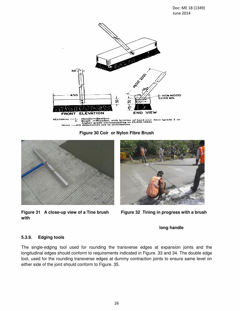
Doc: ME 18 (1349)
June 2014
26
Figure 30 Coir or Nylon Fibre Brush
Figure 31 A close-up view of a Tine brush Figure 32 Tining in progress with a brush
with
long handle
5.3.9. Edging tools The single-edging tool used for rounding the transverse edges at expansion joints and the
longitudinal edges should conform to requirements indicated in Figure. 33 and 34. The double edge
tool, used for the rounding transverse edges at dummy contraction joints to ensure same level on
either side of the joint should conform to Figure. 35.

Doc: ME 18 (1349)
June 2014
27
Figure 33 : Edging Tool or Arising Tool
Figure 34 Round Being arised

Doc: ME 18 (1349)
June 2014
28
Figure 35 : Double Edging Tool or Arising Tool
5.3.10. Graduated Master Straight with Wedge Scale
The master straight –edge, used in conjunction with the graduated wedge (conforming to IS 226) to
check high and low spots along any line on the pavement should consist of a 3 m long mild steel
channel section (conforming to IS 3954 with mild steel stands welded at either end. The dimension
should be as shown in Plat II It should be ensured that the lower face of the straight edge is truly
straight, and that the height of its stand is exactly the same as of the wedge gauge at the zero mark
in the centre. Figure 36 shows Sketch diagram of Master Straight Edge.
Figure 36: Master Straight Edge for Checking Regularity of the top wearing surface.

Doc: ME 18 (1349)
June 2014
29
5.4 Phase IV. Joints –Semi Mechanized Method 5.4.1 Mild steel sections for joint grooves
The mild steel section for forming the groove of dummy contraction joint should consist of a flat
section with flat supporting pieces fixed thereto (Fig.37). Alternatively, T-section of appropriate size
with webs cut at the ends to provide support over the formwork should be adopted. In either case,
to facilitate lifting, the flat supports should be provided with suitable mild steel handles welded
below their extreme ends or with holes. The mild steel section for protection of groove over the
expansion joint filler during construction should consist of rectangular or square bar section,
depending on the expansion joint width, with mild steel handles fixed. Its length should be 5 mm
less than the pavement width to facilitate removal.
The top and bottom edges of these mild steel sections should be shaped to correspond to the
camber of the pavement at the joint.
Figure 37: MS Section for Contraction and Expansion Joint
5.4.5 Diamond Cutter
Rotating disc diamond cutter of travelling type should have appropriate arrangement for lowering
raising the blade to any desired level. It should also have suitable guides for enabling a straight cut
to be made along the desired line. The diamond cutter having water-feeding arrangement may be of
any approved standard make. Figure 38 shows pictorial view of Joint Cutter for cutting contraction
and longitudinal or construction joint.

Doc: ME 18 (1349)
June 2014
30
Figure 38 ( a) : Joint Cutter Figure 38 (b) Joint Cutting with Small Sizes Hand Held
Joint Cutter
Technical Specifications Joint cutting machine :
8-13 HP Horizontally Mounted Water Cooled Engine
Handle Start Engine, 3500 rpm at Cutter Shaft.
Weight : 350 kgs
Chain Sprocket system for forward propulsion
Water consumption of 9 lit/min at point of cutting (max)
5.5 Phase V. Curing – Semi Mechanized Method
5.5.1 Curing Compound and Hessian Cloth: After setting of concrete i.e after about 2-5 hours of
setting of PQC as per environmental conditions, curing compound is spread with a device as shown
in Figure 39 After initial joint cutting, hessian cloth is spread for curing and water is poured gently
over the hessian cloth. Hessian cloth used after initial curing of concrete should be obtained in rolls
of 1 to 1.5 m width. The quality should conform to the requirement of IS 2818. Alternately, other
hessian cloths of approved quality may be used.
Figure 39 Curing Compound Pump for Spraying Curing Compound
5.5.2. Polythene sheeting: The sheeting, if used for membrane curing should have minimum
thickness 125 micron and should be of approved quality and transparent in colour or white in
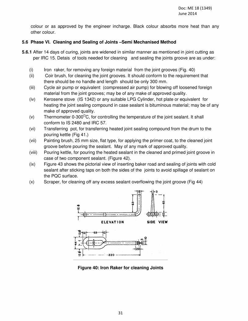
Doc: ME 18 (1349)
June 2014
31
colour or as approved by the engineer incharge. Black colour absorbs more heat than any
other colour.
5.6 Phase VI. Cleaning and Sealing of Joints –Semi Mechanised Method
5.6.1 After 14 days of curing, joints are widened in similar manner as mentioned in joint cutting as
per IRC 15. Detais of tools needed for cleaning and sealing the joints groove are as under:
(i) Iron raker, for removing any foreign material from the joint grooves (Fig. 40)
(ii) Coir brush, for cleaning the joint grooves. It should conform to the requirement that
there should be no handle and length should be only 300 mm.
(iii) Cycle air pump or equivalent (compressed air pump) for blowing off loosened foreign
material from the joint grooves; may be of any make of approved quality.
(iv) Kerosene stove (IS 1342) or any suitable LPG Cylinder, hot plate or equivalent for
heating the joint sealing compound in case sealant is bituminous material; may be of any
make of approved quality.
(v) Thermometer 0-300OC, for controlling the temperature of the joint sealant. It shall
conform to IS 2480 and IRC 57.
(vi) Transferring pot, for transferring heated joint sealing compound from the drum to the
pouring kettle (Fig 41.)
(vii) Painting brush, 25 mm size, flat type, for applying the primer coat, to the cleaned joint
groove before pouring the sealant. May of any mark of approved quality.
(viii) Pouring kettle, for pouring the heated sealant in the cleaned and primed joint groove in
case of two component sealant. (Figure 42).
(ix) Figure 43 shows the pictorial view of inserting baker road and sealing of joints with cold
sealant after sticking taps on both the sides of the joints to avoid spillage of sealant on
the PQC surface.
(x) Scraper, for cleaning off any excess sealant overflowing the joint groove (Fig 44)
Figure 40: Iron Raker for cleaning Joints

Doc: ME 18 (1349)
June 2014
32
Figure 41: Transferring Pot
Figure 42 (a) Wooden/Plastic Tool for Figure 42 (b) Different types of Backer Rod Laying backer rode in Joints
Figure 43 Sealing of Joints with Cold Sealant

Doc: ME 18 (1349)
June 2014
33
Figure 44: Scraper for Removing Foreign Objects
5.6.2 Grinder
Portable electrical grinder with flexible shaft drive of approved design should be used for grinding
any high spots on the hardened concrete surface. (Figure 45).
Figure 45: Potable Electrical Grinder

Doc: ME 18 (1349)
June 2014
34
5.6 Phase VII : Manufacturing, Transportation, Laying and Compaction, finishing and Texturing of Concrete - Mechanized Method
Slipform paver and fixed form pavers are being used under mechanized method for transportation, laying and compaction, finishing and texturing of concrete, details of which are given as under: (i) Batch mix plant with more than 4-bin hoppers is similar as mentioned under semi-
mechanised ( Clause 5.2.1).
(ii) Dumpers/tipping trucks/transit mixers
(iii) A sketch diagram of slip form paver is shown in Figure 46
(iv) Guide-wires for slip-form pavers and stakes (Figure 47 and 48)
(v) Levelling instrument
(vi) Dowel bar inserter (DBI) and Tie bar inserter (TBI), if automatic dowel/tie bar insertion
system is adopted in slip form paving
(vii) Dowel and Tie bars cradles / chairs, for manual dowel placement
(viii) Steel bulk-heads at ends/construction joint
(ix) Finishing and texturing equipment
(x) Liquid curing compound sprayer and fogging agent.
(xi) Steel mobile bridges for manual touching work
(xii) Joint cutting machine
(xiii) Portable pavement protection tents (minimum 150 m length) for hot season operation or
150 m thick water proof polythene sheet ( White or blue colour) Figure 49
(xiv) Sealant application extruder with flexible hose and nozzle
(xv) Scabbler (A tool to remove a thin layer of concrete from a structure i.e air powered
chipping machines/ or scrubbing machine (a tool to rub hard in order to clean. or to
remove dirt or stains)
(xvi) Digital Vernier Callipers
(xvii) Fibre Dispenser
(xviii) Figure 50 to 65 shows different steps of construction.
(xix) Figure 66 shows the testing machine for determining flexural strength of concrete and
Figure 67 shows fibre dispenser, in case fibre are not uniformly dispersed in concrete.

Doc: ME 18 (1349)
June 2014
35
Figure 46 : Diagrams of Different Pavers for laying Pavement, Kerb stone, and drains
Figure 47 View of a Slip-form Paver capable of Figure 48 Laying Polythene sheet paving 16m wide pavement followed by in Front of Paver Texturing and Curing Machine (TCM)

Doc: ME 18 (1349)
June 2014
36
Figure 49 (a) Steel Frame for Tent for Protecting Figure 49(b) Mobile Tent for Protecting Concrete from sun, rain, wind etc Concrete from sun, rain, wind etc
Figure 50 Placing of PQC in Front of Paver Figure 51 Insertion of Tie Bars by Tie Bar Inserter
Figure 52: A view of Dowel Bar Inserter (DBI) Figure 53 A view of a large 3 m long auto-trowel used for final finishing.

Doc: ME 18 (1349)
June 2014
37
Figure 54 A view of a finished PQC surface Figure 55 A view of Texturing & Curing Machine (TCM)
Figure 56 : Liquid curing compound being applied on finished concrete surface Figure 57 Broom Texturing after Finishing
Figure 59 Finished Broomed Surface

Doc: ME 18 (1349)
June 2014
38
Figure 60 Bulk Head to be placed Figure 61. Tools for Sealing of Joints
Figure 62 A View of Concrete Saw. Figure 63 View of Stirrer for Cold Sealant
Figure 64 Sealing Being applied Figure65 View of Texture and sealed joint with Dispenser in Concrete surface

Doc: ME 18 (1349)
June 2014
39
Figure 67 : Testing Beam
Figure 68: Different types of Fibre and Bag Dispenser

35
5.7 . Cleaning and Sealing of Joints
Details of tools needed for cleaning and sealing the joints grooves are given under semi
mechanised method.
5.8 Phase VI Piles, Crash Barriers, Diaphramm wall, tunnles, towers, Kerb Stone and
Concrete Drainage along Earthen Shoulder, abutment wall,
Slip-form kerb stone laying machine and concrete drainage making slip form paving machine with electronic sensor. The pictorial views of the equipments and devices required for construction and laying of kerb stone and concrete drainage along rigid pavement is given in Annexure VII.
MORE DETAILS ARE TO BE PROVIDED EXPERT MEMBERS
5.9 Phase VII. Whitetopping : The specification/pictorial views of the equipments and devices required for construction and laying of whitetopping over bituminous layers or on semi rigid pavement/ recycled semi rigid layer is given in Annexure VIII. Recycling, milling and other stabilization machines rehabilitation and reconstruction of pavements. 5.10 Minimum Balanced Set of Tools, Equipment and Appliances
For smooth progress of work, without any bottlenecks, it is essential to acquire a minimum
balanced set of tools, equipments and appliances needed for different phases of construction.
Details of such a balanced set for small sized constructions envised herein with a daily
concreting output upto 240 cum / hour capacity batching plant, are given in Annexure IX and
X
6. ANCILLARY ITEMS OF TOOLS AND EQUIPMENTS
IN addition to the tools, equipments and appliances covered in preceding clauses, certain
ancillary items will be needed at concrete paving works for taking measurements, marking
distances, storage of water, routine repairs to machinery etc. A list of these items is given at
Annexure VI, IX and X. Though by no means exhaustive, the list includes all such items which
will generally be needed.
7 MAINTENANCE AND UPKEEP OF TOOLS, PLANTS AND EQUIPMENTS
The need for proper maintenance and upkeep of various tools, plants and equipments cannot be
over emphasized to ensured quality construction. Some of the tools and equipments especially tend
to develop inaccuracies and defects with use. Their constant checking and rectification should form
part of daily routine. Points deserving attention in this respect are brought out in Annexure
APPENDIX 1,2 and 3

36
8. EVALUATION OF RIGID PAVEMENT
Before any major repair of rigid pavement, evaluation is carried as per IRC 76 and concrete
cores are cut as per IRC 15 with core cutting machine Figure 69 to 72 and core are
extracted from the slab by a tool as shown in Figure and after capping with approved material
and a tool as shown in Figure and then tested after gaining the strength of the capping material
as of the minimum of original material and then tested as per IS 516.
Figure 69 Core Cutting Machine Figure 70 Core Extracting Tool
Figure 71 Core capping Tools Figure 72 Hot Plate and a pot for heating
sulphur sand mixtures
9. REPAIR OF DEFECTIVE CONCRETE PANEL
Repair of concrete for full depth as per IRC 15 shall be done with full depth cutter avoiding
cutting on dowel bars or tie bars and after full depth cutting panel shall be gently broken and
removed mechanically as shown in Figure 73 to Figure 77.
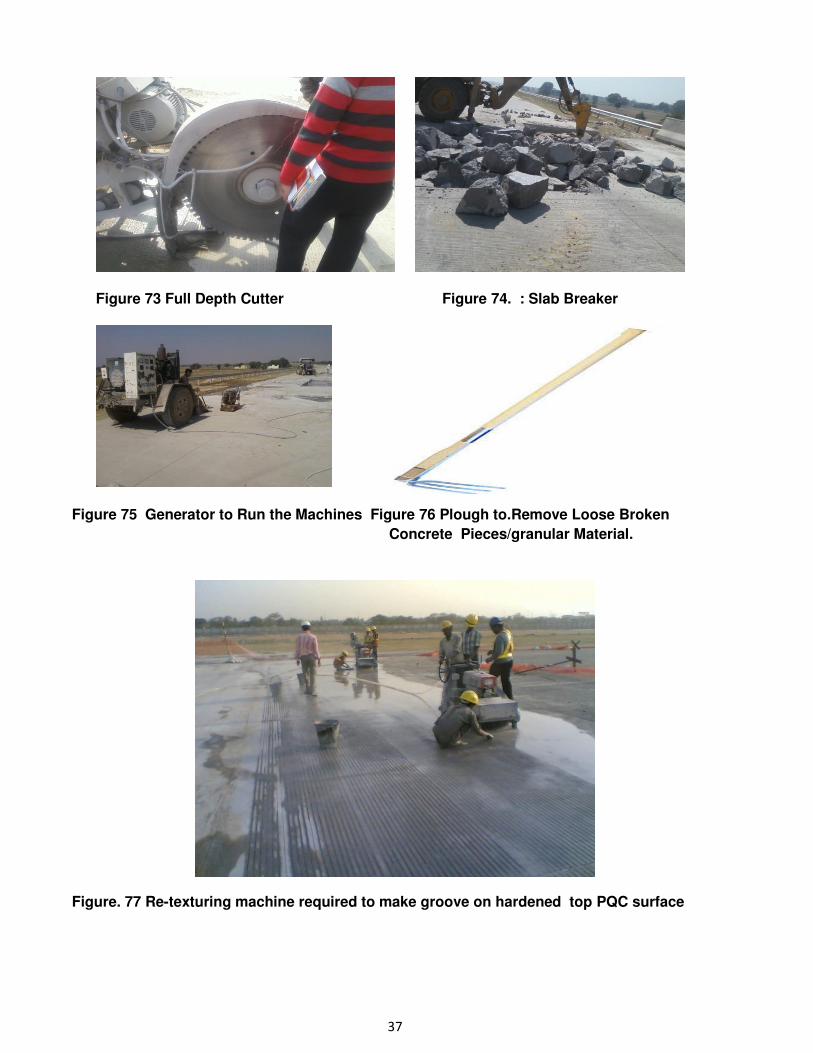
37
Figure 73 Full Depth Cutter Figure 74. : Slab Breaker
Figure 75 Generator to Run the Machines Figure 76 Plough to.Remove Loose Broken
Concrete Pieces/granular Material.
Figure. 77 Re-texturing machine required to make groove on hardened top PQC surface

38
Annexure 1
BACKHOE/EXCAVATOR AND MOTOR GRADER:
Specification Backhoe : There are varieties backhoes available based on their use and
requirements. Following are some general specification:
i) Capacity range : 2- 12 tonnes
ii) Maximum lift height: 2 to 17 m
iii) Width : 2.3 to 2.5
iv) No of wheel; Four wheel drive
v) Forward Length = 3 -9 m
vi) HP : upto 109 HP
vii) Attachments : Front buckets, lifting jib and extension and other as per use
viii) Maximum Engine Power = About 81kW ix) Maximum Dig Depth = About 4.24m x) Operating Weight : 8 to 18 tonnes xi) Peak Torque = 516Nm xii) Bucket Rotation (Speed) : 201° xiii) Dig Depth: 4250 to 5460mm xiv) Maximum Bucket Tearout : 6228kgf xv) Maximum Loader Height : 3840 / 4720 mm xvi) Shovel Capacity : About 1.2m3
Specification Motor Grader: There area various types of motor grader. General specification of
them are given as under:
i) Operating weight – approximate: 15. 8 -22.1 tonnes ii) Maximum combined capacity : : 19.3 – 27.2 Tonne iii) Blade pull at base weight (0.9 traction co-efficient): 10-17 tonnes iv) No. of cylinders : 6 v) Engine Speed (rpm) 1200- 1900 rpm vi) HP 155 -225 vii) Torque : 906 -1234 Nm
:
FigureI- 1 (a) BACKHOE/EXCAVATOR Figure I-1 (b) Motor Grader

39
Annexure II
COMPACTOR/ROLLERS
I Tandem Vibratory Roller: Tandem vibratory roller shall be powered with a 4-cylindered, about 62 kW/84 hp @ 2800 rpm diesel engine. This machine shall have a maximum forward and reverse speed of 10 km/h. (Figure 2 (a)). The machine shall be well equipped with a hydrostatic power steering along with hydrostatic service brakes and a spring loaded, hydraulically released parking brake.
Figure II- 2 (a) Tandem Vibratory Roller
Salient Features of tandem vibratory roller is given as under:
i. Direct hydrostatic vibrator drive ii. Double drum vibration iii. Small turning radius iv. Single lever control v. Central articulated steering vi. Hydrostatic all-wheel drive vii. 2 amplitude, 2 frequencies viii. Low center of gravity ix. Good visibility on drums x. Pressure Sprinkler
II Single Drum Vibratory Road Roller: Salient Features single drum vibratory road roller (Figure 2) is given as under:
i. Max. operating mass 8-15 tonnes
Front module mass 60% Rear module mass 40%
ii. Traction Number of pads 130 Pad area 146 cm2 Speed range (km/ h) 0 – 5 Theor. gradeability 65 Tyre size (8 ply) 23,1×26 Vertical oscillation ±9°

40
iii. Compaction
Centrifugal force, at high amplitude 300 kN Centrifugal force, at low amplitude : 146 kN
iv. Nominal amplitude, 0.8 mm to 1.60 mm v. Vibration frequency, at high amplitude Approximate 33 Hz
The values given against each items are indicative only
Figure II-2 (b): Single Drum Vibratory Roller
Figure II- 2(c) : Single Drum Vibratory roller at Curve Location
Specification Engine i. Type Water cooled turbo Diesel with After Cooler ii. Rated power 110 hp iii. Rated power @ 2,200 rpm iv. Fuel tank capacity About 250 l v. Vibration frequency 50 Hz i. Vibration amplitude 0.4mm ii. Turning radius Approx 5000mm iii. Max travel speed 15km/h iv. Overall dimensions (LXWXH) Approx 5180×1880×2680mm
(i) Drum width 1700mm (ii) Drum diameter 1220mm (iii) Wheelbase 2750mm (iv) Fuel tank capacity 110 (v) Fuel tank capacity 110L
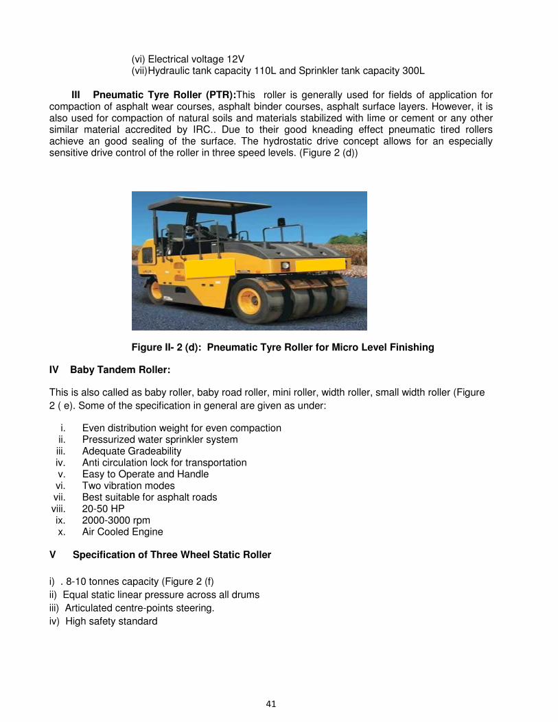
41
(vi) Electrical voltage 12V (vii) Hydraulic tank capacity 110L and Sprinkler tank capacity 300L
III Pneumatic Tyre Roller (PTR):This roller is generally used for fields of application for compaction of asphalt wear courses, asphalt binder courses, asphalt surface layers. However, it is also used for compaction of natural soils and materials stabilized with lime or cement or any other similar material accredited by IRC.. Due to their good kneading effect pneumatic tired rollers achieve an good sealing of the surface. The hydrostatic drive concept allows for an especially sensitive drive control of the roller in three speed levels. (Figure 2 (d))
Figure II- 2 (d): Pneumatic Tyre Roller for Micro Level Finishing
IV Baby Tandem Roller:
This is also called as baby roller, baby road roller, mini roller, width roller, small width roller (Figure
2 ( e). Some of the specification in general are given as under:
i. Even distribution weight for even compaction ii. Pressurized water sprinkler system iii. Adequate Gradeability iv. Anti circulation lock for transportation v. Easy to Operate and Handle vi. Two vibration modes vii. Best suitable for asphalt roads viii. 20-50 HP ix. 2000-3000 rpm x. Air Cooled Engine
V Specification of Three Wheel Static Roller
i) . 8-10 tonnes capacity (Figure 2 (f)
ii) Equal static linear pressure across all drums
iii) Articulated centre-points steering.
iv) High safety standard

42
Figure II- 2 (e) : Baby Road Roller Figure II- 2 (f ): Three Wheel Static Roller v) Emergency brake pedal is standard.
vi) Easy access to engine, hydraulics, devices, hoses, etc.
vii) Sprinkler system with anti-clog package, i.e., a plastic water tank, triple-protection filtration,
etc., and with perfect winterization.
viii) Direct access to spray nozzles from operators station.

43
Annexure III.
Figure III- 3 (a) Disc Harrow to be Fitted with Tractor
Figure III- 3 (b ) Rotavator for site mixing soil Figure III- 3( c) Mechanised Soil Stabilizer Small capacity work (Fitted with Tractor) or Recycling
Figure III- 3 (d) Zippers for Milling and Recycling Figure III-3(f) Soil Stabilization (fully mechanized)
VI Plate Compactor: Plate compactor as shown in Figure 3 (g) is used for compaction of filter media, or for location compaction where screed vibrator is difficult to operate.

44
Figure III- 3 (g): Plate Compactor
Specification for plate compactors are given as under:
i) Engine Air-cooled, 4-cycle, single cylinder Engine Type Petrol or Electrical, ii) Engine Power HP: 5.5 iii) Weight kg : 64 iv) Frequency rpm: 5600 v) Centrifugal Force KN: 10.5 vi) Compaction Depth: 200 mm.

45
ANNEXURE IV
The water tanker shall have water Tank capable of carrying 5000 ltrs. of water and shall be fitted
with a pump at the rear of appliance.
The choice of material to be used in construction of the appliance shall be made with a view to
combine lightness with strength and durability.
The timber shall not be used for body construction.
All parts which form water ways shall be of corrosion resistance material or suitable treated
with corrosion resistance compound. All metal pipe line shall be dipped galvanized after
completing fabrication of pipe line inclusive of flanges/joints. All metal parts exposed to
atmosphere shall either be corrosion resisting material or treated suitably to resist corrosion
resisting material. Pipe used shall at least be of medium duty and shall with stand two times
the maximum working pressure.
WATER TANK
The Water tank mounted on chassis shall be capable carrying 5000 ltrs. of water. It shall be
of welded construction and fabricated out of mild steel sheet. The thickness of the sheet
including baffle shall not be less than 3.0 mm. The tank shall be suitable baffled in both
direction to prevent surge. The baffle shall be of bolted panel type and bolting shall be
done with stainless bolts and nuts. The tank shall be so designed and mounted as to bring
center of gravity of the appliance as low as possible and mounting shall permit full rated
contents of the tank to flow into the pump.
Suitable lifting eye shall be provided on the shell of the tank to unable the tank to be lifted
of the vehicle for repairs etc.
The tank shall be fitted with two man hole of 450 mm dia on the top of the tank. The cover
of the man hole shall be hinged type. The drain pipe shall not be of less than 50mm dia
through out and shall be taken down to the point well below the chassis without reducing
the effective ground clearance. When fully loaded, it shall discharge away from the wheel.

46
One over flow pipe not less than 100 mm dia. shall be fitted to the tank and taken down to
the point well below the chassis without reducing the effective ground clearance when fully
loaded. The pipe shall be so arranged that the water will over flow while refilling the tank
and no water shall over flow when appliance is in motion.
One filling pipe (hydrant connection) of not less than 63 mm shall be fitted to the tank. It
shall be fitted with 63 mm male instantaneous coupling. This connection shall be fitted with
gate valve to prevent water leaking through the filling pipe.
The tank shall be provided with cleaning hole at the bottom of not less than 250 mm dia.
and shall be fitted with bolted cover.
Suitable arrangement shall be provided for self filling the water tank directly from the pump
using 50 mm pipe and control valve.
The water tank with all its fitments shall with stand hydraulic pressure of 0.3kgf/cm2.
All plumbing shall be reasonably accessible for maintenance purpose. Screwed bends,
flange joints shall be avoided as far as possible.
The tank shall be sand blast before giving an epoxy treatment. The epoxy treatment shall
consist of two coats of primer with two coat of epoxy finish.
PUMP
A high cum low pressure light alloy/gunmetal pump shall be fitted at the rear of the
appliance capable of delivering as under:
o 1800Lts/min at 7 kg/cm2 (Normal pressure)
o 250 Lts/min at 30 Kg/cm2 (High pressure)
o Both H.P. & LP can be operated simultaneously.
The pump shall be provided with two delivery outlets of 63 mm quick release coupling and
a suction inlet of 100mm round threaded male coupling as per I.S.
The pump gland shall be self adjusting mechanical seal type.

47
Figure IV- 4 (a)Water Tanker

48
Annexure V The equipments and devices required for construction of lower sub bases and base courses including DLC are given in Annexure V.
(i) EXacavator and Motor grader ( Figure 1) (ii) Pug-mill type mixing plant for granular sub-base/WBM/WMM ( Figure 5 (a), (b)) (iii) Dumpers and Tippers (Figure5 (c), (d)) (iv) Paver finisher with electronic sensor ( Figure (5 (e) (v) Static and Vibratory rollers of 10-12 tonnes weight ( Fig. 2) (vi) Levelling instrument ( Figure 5 (f) ) (vii) Different types of mixing and batching plants with data loggers and other accessories
Figure 5 ( g ) to ( s ) (viii) Rotavator, plougher, tiller Mechanised stabilizer ( Figure 3) Annexure III (ix) Density Testing equipments Figure ( u) and ( v)
Figure V- 5(a) : Wet Mix Macadam Plant Figure V- 5(b):Wet Mix Macadam Plant (working Condition)
The bigger the dump truck, the larger and stronger the engine shall be. The smaller trucks will need a lower horsepower, while the giant earthmover dump trucks will need maximum horsepower that can have up to 3500 horsepower (HP).
Figure V- n5 ( c) Dumpers Figures V- 5 (d) Tippers

49
Figure V- 5 (e) : WMM /GSB Pavers
Figure V- 5 ( f) Different Types of Levelling Instruments
(iii) Paver finisher with electronic sensor (Figure V-5 ( q) and (r))
(iv) Vibratory roller ( FigureII- 2)
(i) Plate compactor (Figure III- 3 (g ))
(ii) Levelling instrument (Figure V-5 ( e)
(iii) Liquid curing compound sprayer (FigureV- 5 ( s)
(iv) Gunny bags / Hessian / coir felt
(v) Pneumatic roller (Figure II-2)
(vi) Scrubber for Grinding Hard Concrete (Figure V- 5 (t ))

50
Figure V- 5 (g): Different types of Mixers Blades (a), (b), and (c) and data Analogue (d)
FigureV- 5 (h) Batching Plant Figure V- 5 (i) Transit Mixer
a b
c d

51
Figure V-5 ( j) Sketch diagram of Bins Figure V- 5 (k) Data logger Indicator
Figure V- 5 (l) Sketch of Batching plant Figure V- 5 (m) Over View of Batching plant
Figure V- 5 (n) Placing of aggregates on Belt Figure V- 5 (o) Batching plant near aggregate Crusher

52
Figure V- 5 (p) Placing of DLC from the Figure V-5 (q) Three lane wide DLC Paver Tipper into the Spreader in working condition
Figure V-5 (r) Finished surface of DLC Figure V-5 (s ) : Curing Compound/Fogging Compound Spreading Machine
Figure V- 5 ( t) Scrubber for Grinding Thin Figure V-5 (u) Mobile Batching and Mixing Plant Hard Concrete (Weigh Batcher with mixer)

53
Figure V- 5 (u) Equipment and Tools for Determining Field Density of Subgarde/Sub base/ Base Course including DLC ( Sand Replacement Method)
Figure V -5 (v ) Rapid Moisture Meter for Determining Moisture Content

54
Annexure VII
DETAILS OF FIELD EQUIPMENT FOR TESTING
The minimum equipment essential for carrying out control and acceptance tests is given below
i. I.S. Test Sieves 45 cm dia, I.S. size45.0 mm, 22.4 mm, 11.2 mm and 4.60 min with lid and pan (as per IS 460-1978)
One set
2) (a) IS Test Sieves, 20 cm dia, IS sizes 2.36 mm, 1.18 mm and 600, 300, 150 and 75 microns, with lid and pan (as per IS 460-1962)
One set
(b) Fine camel hair brush for cleaning the sieves One No. 3) Graduated glass cylinder 200 ml. capacity Two Nos. 4) Semi-automatic balance, 7 kg capacity One No. 5) Semi-automatic balance, 1 kg. capacity One No. 6) *15 cm cube-moulds (for two day’s casting) (as per IS:516-1959 clause
2.9.1) 12 Nos.
7) *75 cm x 15 cm x15 cm beam moulds (for two day’s casting) (as per IS:515-1959 clause 7.4.1)
12 Nos.
8) Tamping roads for compacting cube/beam moulds (as per IS: 516-1959 clauses 2.9.3 & 7.4.2 respectively
2 Nos.(one each)
9) Slump cone, complete with tamping road and 30 cm steel rule (as per IS:1190-1959 clause 3.1.2)
2 sets
10) Dial type spring balance, 100 kg. capacity 1 No. 11) Enamel trays, 30 cm x 15 cm x 5 cm 6 Nos. 12) Pycnometers 2 Nos. 13) Field over with kerosene stove 1 No. 14) Hand operated hydraulic compression testing machine 100 ton capacity
with attachment for flexural testing of beam samples 1 No.
15) Riffle box 2 Nos. 16) Sample tins, beakers, graduated cylinders, wash-bottle, thermometer (0-
100 C), steel spatula, pair of tongs etc.
17) Scoop, crowl and shovel for harding the materials One each 18) Core cutting machine for 10 cm or 15 cm cores 1 No. N.B. * In case the max. size of the aggregate employed at a project does not exceed 10 mm, 10 cm cube moulds and 50 cm x 10 cm x 10 cm beam moulds may be used as permissible in IS: 456-1964 Note : The list is meant for a daily output of about 20-30 cu.m. of concrete. But except in the case of beam/cube moulds, the equipment listed can adequaltely cope with a daily concrete output of upto 90 cu.m. provided that work heads are in close vicinity so as to enable the same equipment to be used centrally. Additional 6 beams/cube moulds will have to be provided in this case for every additional 30 cu.m. of concreting per day. In case the workheads are far apart and it is not convenient to use the same equipment for several workheads, the minimum required equipment will have to be provided at each workhead separately.

55
Annexure VIII MINIMUM BALANCED SET OF TOOLS, EQUIPMENT AND APPLIANCES No. required No.
standby 1. a) Suitable Compaction Equipment 1 -- b) Bhisty (water-carriers) 6 --
2. Pick-axe
Spade Shovel
12 12 6
-- -- 2
3. Scratch Template or Strike Board 1 1
4. a) Formwork for two day’s work b) Stakes for formwork
A few lengths 100
25
5. Sieving screens One set One set
6. Weigh Batcher (Double-Hopper, Swing Type) 1 - 7. Aggregate Measuring Boxes (for volume batching only)
Alternative to No.6, in case permitted
One set (0.015, 0.03,
One set 0.0375m )
8. Water Measures One set one set (5,2,1 and 0.5 litre)
9. Concrete Mixer 1 1 (desirable but not mandatory)
10. Concrete Vibrators a) Internal Vibrators
i. For highway pavements ii. For airfield pavements
b) Screed Board Vibators
1 3 1
1 1 1
11. Wheel Barrows (0.08-0.11m capacity)
8 (may be increased depending upon lead)
12. Hand Tamper Board 1 1 13. Float 4 2 14. Straight edge 1 1 15. Bulk-head 2 1 16. Mild Steel Sections for Making Joint Grooves
a) For expansion joints b) For contraction joints
1 5
- 1
17. Edging Tools 1 1

56
Edging tool Double edging tool
-
18. Canvas Belt 2 -
19. Long-handled coir Broom 1 5
20. Graduated Master Straight Edge with wedge gauge Diamond Cutter (optional Portable Grinder
1 4
- (3 diamond blades) 2
21. Wooden Bridges 4 2 22. Hessian Cloth Suffiecient to cover one
day’s work (200 sq.m.) 23. Tools for Joint Sealing
a) Iron Raker b) Coir Brush c) Cycle Pump d) Kerosene Stove e) Thermometer (0-300 C) f) Painter Brush (25 mm) g) Transferring Pot h) Pouring Kettle i) Scraper
1 1 1 1 1 1 1 1 1
- - - - 1 3 - - -
Replacements for any items becoming unserviceable should be made promptly so that the required number alongwith needed standbys for smooth working is always available.

57
Annexure IX ANCILLIARY ITEMS OF TOOLS, EQUIPMENT, ETC. FOR CONCRETE PAVING WORKS No. required
For checking levels and marking distances Dumpy level and Levelling Staff 1 each Steel Tape (30 m), Metallic Tape (30 m) 1 each Coconut Coir Rope ( 12 mm dia) 2 kg. Ranging Rods 5 For Preparation of Sub-base for Concreting
Coir Brushes 10 Metal Hand Rammer (as per IS: 4183-1967) 1 Rose Cans 6 For Manufacture of Concrete including Handling of Materials
Panjas 6 Canc Baskets 24 Empty Drums for water storage (200 litre capacity 25 Empty Tins (18 litre capacity) 10 Iron Pans 24 M.S. Sheets (3m x 1.1/2 m x 6mm approx.) 3 Knife 1 Tarpaulins (5m x 5m approx) 4 For Fixing & Removing Formwork
Mason’s Thread 2 balls Hammers ( 5 kg, 1/1 kg) 2 each Crow Bar (40-50 mm dia, 1500 mm length) 1 Mason’s Trowel and Straight Edge 1 each Spirit Level 9 30 mm) 1
Spares for Repairs to Equipment
Assorted nuts, bolts, nails and screws Spares for concrete mixer, screed vibrator (especially handle-springs & rubber-belts), internal vibrator and weigh batcher. Tool kit for general purpose including sets of pliers, wrenches, etc. This does not include items such as storage shed for cement, water storage tank, appurtenance for traffic diversion and regulation, etc. items which do not strictly form a part of tools, equipment and appliances, but which are nevertheless essential for any concrete paving job.

58
Annexure X
ROUTINE MAINTNANCE AND UPKEEP OF TOOLS, EQUIPMENT AND APPLIANCES The following points should form a part of routine daily check-up of plant so as to ensure quality construction : Scratch Template or Strike Board : The truness of setting of nails to cross-profile should be checked daily before commencement of work. Formwork : (1) The straightness of formwork in bot the horizontal and vertical planes should be ensured before each use. When fixed, it should be checked with a 3 m straight edge and any departure greater than 1.5 mm duly rectified. (2) The formwork should be thoroughtly cleaned and should not have any foreign material sticking thereto. Sieving Screens : It should be ensured that the sieves are thoroughly clean and that there is no no displacement or breakage of the mesh wires, etc. Weight Batcher : (1) The calibration of the weigh batcher scales should be checked regularly be means of a set of standard weights over the full working range in use. (2) The knife-edge supports should be regularly cleaned. (3) Free movement of the dial needle should be ensured. Measuring Boxes : Wherever volume batching is permitted, the trueness of shape and correctness of dimensions of the measuring boxes should be ensured. Water Measures : The calibration of the water measures should be checked regularly against standard graduated cylinders. Concrete Mixer : (1) Any worn out mixer blades (worn more than 20 mm) should be replaced. (2) After any break, in construction longer than 20 minutes and at the end of the day’s work, the mixer drum should be thoroughly washed and cleaned. Concrete Vibrators: Regular servicing of the units should be got done to keep them in good working order. Surface Finishing Tools : Floats and straight edge, should be daily checked before use for trueness, and any departure from a true plane surface should be rectified before use. Mild Steel Sections for Marking Joint Grooves : The trueness and straightness should be checked before use, especially in case of the mild steel flats for making contraction joint grooves, as they are sometimes likely to get bent during insertion in the concrete. Canvas Belt : Should be thoroughly washed and cleaned after each use. Long Handled Coir Broom : The coir bristles should be checked for wear and worn out brooms should be replaced. Graduated Master Straight Edge with Wedge Gauge : The trueness of the straight edge and wedge gauge should be checked before use. It will not be normally necessary to make this check daily, and initial checking before commencement of work should generally suffice.

59
DEFINITIONS: 1. Plants: Plant includes: i) any machinery, equipment, appliance, container, implement and tool; and
ii) any component of any of those things; and
iii) anything fitted or connected to any of those things
2. Apparatus or Setup: Equipment designed to serve a specific function
3. Tool: A device or implement, especially one held in the hand, used to carry out a particular function. synonyms: Implement, instrument, apparatus, gadget, appliance, machine, mechanism, aid etc or
Tool is a device, such as a saw, used to perform or facilitate manual or mechanical work
4. Equipment: Equipment is an instrumentality needed for an undertaking or to perform a service
5. Devices
i) a thing made or adapted for a particular purpose, especially a piece of mechanical or electronic equipment. or
ii) a plan, method, or trick with a particular aim.
iii) A contrivance or an invention serving a particular purpose, especially a machine used to perform one or more relatively simple tasks.
iv) An object, machine, or piece of equipment that has been made for some special purpose.

60
References :
1. David Phillips The Guardian, Monday 5 March 2001 03.01 GMT , Joseph Cyril Bamford (JCB), June 21 1916; - March 1 2001)
2. IRC: 15 2002 Standard Specifications and Code of Practice for Construction of Concrete Roads (Third Revision)
3. IRC: 58-2002 : Guidelines for the Design of Plain Jointed Rigid Pavements for Highways (Second Revision)
4. MORTH Handbook on road construction machinery, 1985 5. MORTH Specification for Road and Bridge Works 2013 (Vth Revision) 6. www.Jcb/motorgrader/exacavator/trucks.com 7. www.batchingplant/jointcutte.comr 8. www.floater.com 9. www.geoguage.com 10. www.wmmplant.com 11. NICE Bangalore, Bombay Municipal Corporation and JP Associates Internal Reports 12. www.vonark.com 13. www.trimmer.com 14. www.mbw.com 15. www.wirtzen.com 16. www.opolo.com 17. www.volvo.com 18. www.Cromptongreaves.com 19. www.scievevibrating 20. www.RBIGrade81alchmist 21. FHWA ICT-11-076 – Early entry saw, 2011. 22. www.Fibredispenser 23. www.WHS Regulations: Facilitator Guide V1.11.11. 24. http://www.thefreedictionary.com/equipment 25. http://wordnetweb.princeton.edu/perl/webwn?s=equipment 26. www.merriam-webster.com/dictionary/device

FORMAT FOR SENDING COMMENTS ON BIS DOCUMENTS
(Please use A4 size sheet of paper only and type within fields indicated. Comments on each clauses/sub-
clauses/table/fig. etc be started on a fresh box. Information in Column 4 should include reasons for the comments
and suggestions for modified wording of the clauses when the existing text is found not acceptable. Adherence to
this format facilitates Secretariat’s work) It is desirable to send comments through email at : [email protected] .
IS. No./ Doc. No.:
TITLE :
NAME OF THE COMMENTATOR /ORGN.: _________________________
Sl.
No.
Clause/Subclause/
para/table/fig.
No. commented
Comments
Justification
Proposed
change