hp – pneumatic - hl · pdf file hp pneumatic compressors hp – pneumatic system...
TRANSCRIPT

HP – PNEUMATIC
System Solutions for Industry
HP Pneumatic Valves HP Pneumatic Dryers HP Pneumatic Compressors HP Pneumatic Systems
E1.0.1 JAN09 HP-Pneumatic
SCHRUPP
HL Hydraulik GmbH
www.hl-hydraulik.de
Kupferhütte 5c D-57562 Herdorf
Tel 02744-9324-0 Fax 02744-9324-56
R

Hand operated valves of the Series HAV provide leakfree operation for high pressure pneumatic or water service. Their robust construction and special adjustable spindle-sealing allow operation under extreme conditions with a very long lifespan. The valves can accept flow in both directions.
Product Range: NG 8mm PN 200bar
NG 15mm PN 64bar
NG 25mm PN 64bar
Accessories:
Reduction from NG 15 to NG 10 with outside-screw thread M18 x 1.5
Tube fitting connection to Gal. ZN 1201 DIN 50961
E1.1.1 JAN09 HP-Pneumatic
SCHRUPP
HL Hydraulik GmbH
www.hl-hydraulik.de
Kupferhütte 5c D-57562 Herdorf
Tel 02744-9324-0 Fax 02744-9324-56
R
HAND OPERATED VALVES
TYPE HAV
Type
ND
Prodnr Prodno
Fuß Socket
Entlastung Vent a b c d e f g h i S1 Rohr
Pipe Masse (Kg)
HAV 15 160523 80 9 M26x1,5 112 19 24 15/18 0,55
HAV 15 160525 x 80 9 17 M26x1,5 8 44 60 112 19 24 15/18 0,59
HAV 15 160524 x 80 9 M26x1,5 112 19 24 15/18 0,55
HAV 15 160526 x x 80 9 17 M26x1,5 8 44 60 112 19 24 15/18 0,59
HAV 25 160527 105 12 M36x2 113 25 36 25/28 0,89
HAV 25 160528 x 105 12 M26x2 113 25 36 25/28 0,89

Order-Information HAV 08 Pno.: 504242 NG 8mm PN 350bar
Product Nr: 504242
Accessories HAV 08 Tube fitting Connection per: Gal. ZN 1201 DIN 50961 for tube D = 8/12mm Order nr: HAV 08 EOV
HAV Tube fitti ng Connection per: Gal. ZN 1201 DIN 50961 for tube D = 15/18mm Order nr: HAV 15 EOV Reduction from M26x1.5 to M18x1.5 thread Order nr.: HAV 15 RED10
HAV 25 Tube fitting Connection per: Gal. ZN 1201 DIN 50961 for tube D = 25/28mm Order nr.: HAV 25 EOV
Spare parts kit Consisting of:
Pos Name
1 O – Ring (u-ring)
3 Disk
4 Seal Kit
Order Information HAV 15 VTS HAV 25 VTS
E1.1.2 JAN09 HP-Pneumatic
SCHRUPP
HL Hydraulik GmbH
www.hl-hydraulik.de
Kupferhütte 5c D-57562 Herdorf
Tel 02744-9324-0
R
HAND OPERATED VALVES
TYPE HAV
Fax 02744-9324-56 [email protected]

NP 64bar
ND 15 and ND 25mm
Complete with EO fittings
Gal. ZN 1201 DIN 50961
ND Seat a b c d Mass Partno.
15 soft M26 x 1,5 9 80 60 0,4 Kg 160535
25 soft M36 x 2 12 105 58 0,5 Kg 160537
Ordering code and example: Type, Size, Pressure
RSV 15 – 64
Pressure difference for opening 2bar
NP 100
ND10 NP200 and ND25 NP100
Complete with EO fittings
Gal. ZN 1201 DIN 50961 ND Connection length
10 M 20 x 1,5 80
25 M 36 x 2 85
Ordering code and example: Type, Size, Pressure
RSV 10 – 200
E1.2 JAN09 HP-Pneumatic
SCHRUPP
HL Hydraulik GmbH
www.hl-hydraulik.de
Kupferhütte 5c D-57562 Herdorf
Tel 02744-9324-0
R
NON RETURN VALVES
TYPE RSV
Fax 02744-9324-56 [email protected]

Pressure Maintaining and Pressure Maintaining Check Valves series DHV and DRV are mounted between the condenser and the compressed air vessel. These valves maintain a constant pressure at the condenser and help to facilitate water separation from the air. The higher the pressure at the valve, the better the water-separation. Their robust construction allows their use under extreme conditions with a very long lifespan.
Ordering Information DHV 16 - 451263 Pressure Maintaining Valve NG16mm PN15-60bar DHV 12 - 451262 Pressure Maintaining Valve NG12mm PN60-350bar DHV 05 - 504270 Pressure Maintaining Valve NG 5mm PN60-350bar DRV 05 - 450050 Pressure Maintaining Check Valve NG 5mm PN60-350bar
Technical Data DHV 05 DRV 05 DHV 12 DHV 16 Flow rate with 5bar dp - - 750 1500 l/min
with 220 bar dp 3500 3500 l/min
with 10bar dp 160 160 2500 5000 l/min with 15bar dp 4600 9200 l/min
Minimum pressure difference 10 10 5 5 bar Max. Working pressure 350 350 350 60 bar Pressure range 60-350 60-350 30-350 15-60 bar Mass 10 18 120 120 N Hous ing material MS MS MS MS Seals Buna -N Buna -N Buna -N Buna -N Tube-connection size 12 12 20 28 mm
E1.3.1 JAN09 HP-Pneumatic
SCHRUPP
HL Hydraulik GmbH
www.hl-hydraulik.de
Kupferhütte 5c D-57562 Herdorf
Tel 02744-9324-0
R
PRESSURE MAINTAINING
VALVES TYPE HAV
Fax 02744-9324-56 [email protected]

DHV 16
E1.3.2 JAN09 HP-Pneumatic
SCHRUPP
HL Hydraulik GmbH
www.hl-hydraulik.de
Kupferhütte 5c D-57562 Herdorf
Tel 02744-9324-0 Fax 02744-9324-56
R
DHV 16
Bestellnr. Dichtsatz / Orderno. seal kit: DHV 16 - VTS - 451263 - 92
80
120
202
3
00
30
60
28 (2
5 op
tion)
Befestigungslöcher Fixing Holes M8
Einstellung des Öffnungsdruckes Opening Pressure Adjustment
75
PRESSURE MAINTAINING
VALVES TYPE HAV

Bestellnr. Dichtsatz / Orderno. seal kit: DHV 12 - VTS - 451262 - 92
E1.3.3 JAN09 HP-Pneumatic
SCHRUPP
HL Hydraulik GmbH
www.hl-hydraulik.de
Kupferhütte 5c D-57562 Herdorf
Tel 02744-9324-0 Fax 02744-9324-56
R
DHV 12
80
120
202
3
30
30
30
60
20
Befestigungslöcher Fixing Holes M8
Einstellung des Öffnungsdruckes Opening Pressure Adjustment
75
PRESSURE MAINTAINING
VALVES TYPE HAV

Ordering Information Spare parts kit DHV 05 VTS
DHV 05
Ordering Information Spare parts kit DRV 05 VTS
DRV 05
E1.3.4 JAN09 HP-Pneumatic
SCHRUPP
HL Hydraulik GmbH
www.hl-hydraulik.de
Kupferhütte 5c D-57562 Herdorf
Tel 02744-9324-0 Fax 02744-9324-56
R
PRESSURE MAINTAINING
VALVES TYPE HAV

Pressure Maintaining Valves are mounted between the condenser and the compressed air vessel. These valves maintain a constant pressure at the condenser and help to facilitate water separation from the air.
The higher the pressure at the valve, the better the water-separation. Pressure Maintaining Valve comlplete with EO fittings GAL. ZN 1201 DIN 50961
Sealing kit Order No:
DHV08 VTS
1 O-Ring 2 O-Ring 3 O-Ring 4 Seal 13 x 3
Size: 8mm Ordering Code and Example Seat: soft Type, Size, Pressure, Pnr. Mass: 0,5Kg DHV 08 - 45 - 160540 Max Pressure: 45bar
Example:
Valve combination DMV 08 and DHV 08. This combination can be used to reduce a pressure in a system and to protect the secondary circuit against overpressure.
E1.3.5 JAN09 HP-Pneumatic
SCHRUPP
HL Hydraulik GmbH
www.hl-hydraulik.de
Kupferhütte 5c D-57562 Herdorf
Tel 02744-9324-0 Fax 02744-9324-56
R
PRESSURE MAINTAINING
VALVES TYPE HAV

SAFETY VALVE TYPE V600 ORDERINGNO SVE06 - 87202 Application: Schrupp safety valves type SV06-1 and SV06-2 are spring loaded valves designed to protect compressors from over-pressurization. The Schrupp safety valves can also be used to protect pressure vessels containing non-poisonous gases.
Special characteristics: TUV approval up to 350 bar Acc. To 97/23/EC, Group 2, Div IV
Low hysteresis and good operational control even under adverse conditions. Compact design Robust design Easy to maintain
Technical Data: DN6 Opening Pressure: Type SV06-1 Pressure range 150 -350bar 350 bar
Type SV06-2 Pressure range 55 - 150bar150 bar
Flow rate(liters/min) = 32.2 x pressure(bar) Ambient Temperature: 0-70 degrees C.
proportional safety valve, mass 1,3kg.
Notice: Valves are shipped with plugged ports. Please remove before installation
E1.4.1 JAN09 HP-Pneumatic
SCHRUPP
HL Hydraulik GmbH
www.hl-hydraulik.de
Kupferhütte 5c D-57562 Herdorf
Tel 02744-9324-0 Fax 02744-9324-56
R
SAFETY VALVES
TYPE SVE06

Ordering example SVE 06 - 55-66 - 87202 Type Pressure set point
Set Pressure
Spare parts kit numbe: SVE 06 VTS 87202-92
Functional Description: Port R is connected to the compressor or high pressure vessel. In the event of over-pressure, the ball lifts from the seat and bleeds pressure through the side outlet port. The elbow fittings can be arranged to send the air in any direction. To check valve function, turn lever #21 counter-clockwise to valve housing, #1. This test will not affect the pressure set point. The set pressure can be adjusted by turning lever #21 after loosening locking nut #20. (Turn clockwise to increase pressure set point.) After adjustment, re-tighten locking nut #20. The valves do not require regular servicing. Periodically, tests are required. according to 97/23EC.
Mark Number Description 5 Seat 15 O-ring 16 O-ring 18 Back up ring Note: The set pressure for type SV06 can be adjusted in the range as shown below: On request, the adjustment can be made by TUV or on the Schrupp test stand.
SV06 Set pressure in bar Set pressure in bar 150 - 175 55 - 66 175.1 – 220 66.1 – 85 220.1 - 350 85.1 – 110 110.1 – 135 135.1 - 150
E1.4.2 JAN09 HP-Pneumatic
SCHRUPP
HL Hydraulik GmbH
www.hl-hydraulik.de
Kupferhütte 5c D-57562 Herdorf
Tel 02744-9324-0 Fax 02744-9324-56
R
SAFETY VALVES
TYPE SVE06
Pressure [bar] 4.5 6.1 8.1
13.1 18.1 21.1 25.1 30.1 35.1 41.1
- - - - - - - - - -
6 8
13 18 21 25 30 35 41 44
Accessory: reducer to NG 15 Model number: SVE30 RED 15 - 89062-92
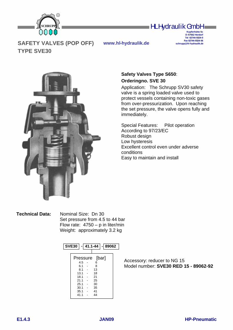
Safety Valves Type S650: Orderingno. SVE 30 Application: The Schrupp SV30 safety valve is a spring loaded valve used to protect vessels containing non-toxic gases from over-pressurization. Upon reaching the set pressure, the valve opens fully and immediately. Special Features: Pilot operation According to 97/23/EC Robust design Low hysteresis Excellent control even under adverse conditions Easy to maintain and install
Technical Data: Nominal Size: Dn 30 Set pressure from 4.5 to 44 bar Flow rate: 4750 – p in liter/min Weight: approximately 3.2 kg
- 41.1-44 - 89062SVE30
E1.4.3 JAN09 HP-Pneumatic
SCHRUPP
HL Hydraulik GmbH
www.hl-hydraulik.de
Kupferhütte 5c D-57562 Herdorf
Tel 02744-9324-0 Fax 02744-9324-56
R
SAFETY VALVES (POP OFF)
TYPE SVE30

1. Shipping and Storage
Maintenance and Operation:
1. Shippingand Storage
During transportation or storage, the valve should be locked in the open position by use of the manual handle. All ports must be plugged. To open the valve, the lever should be moved against the spring force to the end position and fixed by the holding clamp.
On pressure vessels or pipes with minimum inside diameter of 1 inch. For installation, use only original seals; never use glue or other additional seal materials.
2. Installation
3. Adjustment of Set Pressure
After removing the pin the set pressure can be changed, by turning the thread cap clockwise (increases set pressure) or counter-clockwise (reduces set pressure).
4. Noise protection
Because of the possible production of high noise levels, we recommend the use of an ear protection.
Spare parts kit Part Qty Designation 4 1 Piston 5 1 Compression spring 6 1 O-Ring 8 1 Torsion spring 13 1 Seal 45/58 x1 15 1 Valve insert 25 1 O-Ring 26 1 Seal 30/39 X 5
Order No. SVE 30 VTS
Mode of operation:
With increasing pressure the valve insert (15) rises out of its seat and vents air to atmosphere. Then the piston (4) rises out of its seat and the valve opens.
Open:
Closing: After blowing the pressure off over the piston (4) the valve insert (15) closes fast; the closing process of the piston (4) is delayed until the pressure build-up over the piston (4) escapes through the drilling in the piston. Thus, closing of the piston (4) takes place not via the strength of the spring (5), but with the pressure on the differential area of the piston (4) opposite the valve seat.
E1.4.4 JAN09 HP-Pneumatic
SCHRUPP
HL Hydraulik GmbH
www.hl-hydraulik.de
Kupferhütte 5c D-57562 Herdorf
Tel 02744-9324-0 Fax 02744-9324-56
R
SAFETY VALVES (POP OFF)
TYPE SVE30

Sicherheitsventil für Druckluft mit Baumusterprüfung. TÜV approved Safety Valve for compressed air. 97/23/EC, Gruppe2, KategorieIV Einstelldruck / Set Pressure: 0,3 – 50 bar Betriebstemperatur / Operating Temperature: max 180°C DN: 10mm Bestellbeispiel / Ordering Example SVE10 - G1/2 - 45 - Teilenr Einstelldruck / Set Pressure Anschluß/Connection Type
Teilenr. Anschluß Connection
Druckbereich Pressure
SW A C D
850803 G3/8” 0,3 – 8,5 bar 27 22 75 12 8,6 – 40 bar 27 22 95 12 40,1– 50 bar 27 22 120 12 G1/2” 0,3 – 8,5 bar 27 26 75 14 8,6 – 40 bar 27 26 95 14 40,1– 50 bar 27 26 120 14 G3/4“ 0,3 – 8,5 bar 32 32 75 16 8,6 – 40 bar 32 32 95 16 40,1– 50 bar 32 32 120 16
Dimensions in mm
SCHRUPP
HL Hydraulik GmbH
www.hl-hydraulik.de
Kupferhütte 5c D-57562 Herdorf
Tel 02744-9324-0 Fax 02744-9324-56
R
E1.4.5 JAN09 HP-Pneumatic
SAFETY VALVES
TYPE SVE 10
850803 850803 850804 850804 850804 850805
850805 850805
Partno.
SW
A
D
C

Safety devices of the type SHE are used to protect downstream storage vessels which are being fed by a higher operating pressure, against over pressurization. As opposed to the function of a typical safety valve, the Schrupp SHE valve protects the lower rated pressure vessel by closing the interconnection between the two vessels once the set pressure has been reached. In this way, the operational (low pressure) vessel is protected, while at the same time, maintaining the stored pressurized air necessary to ensure operation of the selected component, such as electrical switch gear.
The Schrupp SHE safety device includes the following elements:
a. Locking valve with electrical position indication switch.
b. Solenoid actuated, pilot operated, 2/2 way sluice valve.
c. Throttling Device. d. Pressure Relief Valve
e. Pilot Throttle.
f. Bleed Valve.
Technical Data TYPE SHE 06 SHE 20 Nominal size 20 10 mm Primary pressure 64 64 - 200 bar Secondary pressure 5 – 40 15 – 40 bar Max flow rate 56,000 56,000 l/min Mass ca. 320 ca. 320 N Nominal size of pressure relief valve
6 6 mm
Port P M36 x 2 G 3/8“ Port T M36 x 2 M36 x 2 Port ST connection for pipes with outside dimension:
10 10 mm
According to 97/23/EC
High pressure storage vessel
P
S ST Low pressure operating vessel
a
b c
d
e
f
SCHRUPP
HL Hydraulik GmbH
www.hl-hydraulik.de
Kupferhütte 5c D-57562 Herdorf
Tel 02744-9324-0 Fax 02744-9324-56
R
E1.5.1 JAN09 HP-Pneumatic
SAFETY DEVICES
TYPE SHE

SCHRUPP
HL Hydraulik GmbH
www.hl-hydraulik.de
Kupferhütte 5c D-57562 Herdorf
Tel 02744-9324-0 Fax 02744-9324-56
R
E1.5.2 JAN09 HP-Pneumatic
SAFETY DEVICES
TYPE SHE

Ordering code SHE 06 24GL Voltage 24v DC = 24GL =24GL 240v/60Hz = 240W ,,, Inlet pressure up to 64 bar = 064 ,,,Inlet pressure up to 200 bar = 200 Spare parts kit: SHE 06 24GL VTS
Port Connections SHE 06 P,T - M36 x 2 St - 10 mm SHE 20 P - G 3/8” T - M36 x 2 St - 10 mm
SCHRUPP
HL Hydraulik GmbH
www.hl-hydraulik.de
Kupferhütte 5c D-57562 Herdorf
Tel 02744-9324-0 Fax 02744-9324-56
R
E1.5.3 JAN09 HP-Pneumatic
SAFETY DEVICES
TYPE SHE

Schrupp pressure reducing valves, type DMV08 are used to reduce pneumatic system pressure from a maximum primary pressure of 200 bar to a maximum secondary pressure of 60 bar. Upon reaching the adjusted outlet pressure, the leakfree Schrupp DMV08 closes. The robust design of the Schrupp pressure reducing valve is very compact and provides exact pressure control.
Technical Data Nominal Size: 8mm Inlet port: G 3/8“ Outlet port: G 1“ Max Primary pressure: 200bar Max Secondary pressure: 60bar Min Secondary pressure: 5bar Flow rate 33,000L/min at 180bar dp Mass: ca. 45N Ambient Temperature 0-70°C Ordering Code DMV 08 45 (5-45bar Primary press.) DMV 08 60 (45-60bar Primary press.) Spare Parts Kit DMV 08 VTS includes: Pos Stk Description
4 1 Piston 11 1 Seat Ring 14 1 O-Ring 15 1 O-Ring 16 1 O-Ring 17 1 O-Ring 21 1 Seal 31 1 O-Ring
SCHRUPP
HL Hydraulik GmbH
www.hl-hydraulik.de
Kupferhütte 5c D-57562 Herdorf
Tel 02744-9324-0 Fax 02744-9324-56
R
E1.6.1 JAN09 HP-Pneumatic
PRESSURE REDUCING VALVE
Pno.155308
TYPE DMV 08 AP20380

Schrupp pressure reducing valves, type DMV20 are used to reduce pneumatic system pressure from a maximum primary pressure of 40 bar to a maximum secondary pressure of 25 bar. Upon reaching the adjusted outlet pressure, the leakfree Schrupp DMV20 closes. The robust design of the Schrupp pressure reducing valve is very compact and provides exact pressure control.
Technical Data
Size: 20mm
Inlet port: G 1“
Outlet port: G 1“
Max inlet-pressure: 40bar
Max outlet-pressure: 25bar
Min outlet pressure: 0,5bar
Flowrate 7.800L/min max
Mass: apr. 4Kg
Temperature 0-60°C
Ordering code
DMV 20 - 453419
SCHRUPP
HL Hydraulik GmbH
www.hl-hydraulik.de
Kupferhütte 5c D-57562 Herdorf
Tel 02744-9324-0 Fax 02744-9324-56
R
E1.6.2 JAN09 HP-Pneumatic
PRESSURE REDUCING VALVE
TYPE DMV 20
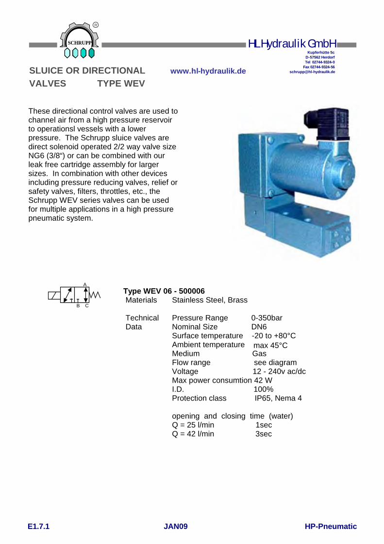
These directional control valves are used tochannel air from a high pressure reservoir to operationsl vessels with a lower pressure. The Schrupp sluice valves are direct solenoid operated 2/2 way valve size NG6 (3/8“) or can be combined with our leak free cartridge assembly for larger sizes. In combination with other devices including pressure reducing valves, relief or safety valves, filters, throttles, etc., the Schrupp WEV series valves can be used for multiple applications in a high pressure pneumatic system.
Type WEV 06 - 500006 Materials
Stainless Steel, Brass
Technical Data
Pressure Range Nominal Size Surface temperature -20 to +80°C Ambient temperature Medium Gas Flow range see diagram Voltage 12 - 240v ac/dc Max power consumtion 42 W I.D. 100% Protection class IP65, Nema 4 Consumption opening and closing time (water) Q = 25 l/min 1sec Q = 42 l/min 3sec Voltage Tolerance
0-350bar DN6
max 45°C
Gas
see Diagram 12-240V ac/dc
42W
1
IP 65,3 se Nema 4
+5 to –10% Opening and closing time in
water Q = 25 l/min 1 sec Q = 45 l/min 3 sec
SCHRUPP
HL Hydraulik GmbH
www.hl-hydraulik.de
Kupferhütte 5c D-57562 Herdorf
Tel 02744-9324-0 Fax 02744-9324-56
R
E1.7.1 JAN09 HP-Pneumatic
SLUICE OR DIRECTIONAL
VALVES TYPE WEV
A
B C

ORDERCODE TYPE: WEV 06 P250 500006 024G 24V DC 110W 110V/50Hz (60Hz) 220W 220V/50Hz (60Hz) Pressure-range up to 50, 250, 400bar Dimensions
4xM8 max D6 A1 B C
A2 D 40 D 60
A B C
179
60 73 180
B A C 71
SCHRUPP
HL Hydraulik GmbH
www.hl-hydraulik.de
Kupferhütte 5c D-57562 Herdorf
Tel 02744-9324-0 Fax 02744-9324-56
R
E1.7.2 JAN09 HP-Pneumatic
SLUICE OR DIRECTIONAL
VALVES TYPE WEV

These directional control valves are used to channel air from a high pressure reservoir to operationsl vessels with a lower pressure. The Schrupp sluice valves are direct solenoid operated 2/2 way valve size NG6 (3/8“) or can be combined with our leak free cartridge assembly for larger sizes. In combination with other devices including pressure reducing valves, relief or safety valves, filters, throttles, etc., the Schrupp WEV series valves can be used for multiple applications in a high pressure pneumatic system.
Type WEV 06 R Materials
Stainless Steel, Brass
Technical Data
Pressure Range Nominal Size Surface Temperature Ambient Temperature Medium Flow Renge Voltages Max. Power Consumption I.D. Electrical Protection Class Voltage Tolerance
0-250bar DN6 -20 to+80°C max 45°C Gas see Diagram 12-240V ac/dc 43W 100% IP 65, Nema 4 +5 to –10%
Functional Description
When solenoid 1 is de-energized, spring 9 pushes the piston against seat 8a. Port 1 is blocked, port 2 is connected to port 3. When solenoid 1 is energized, the piston will be shifted against seat 8b. Port 2 is blocked and port 1 is connected to port 3.
Spare Parts WEV 06 R Item
3 4 5 6 7 8
Quantity 1 1 2 4 6 2
Description Seal Rd-Ring Turcon Step seal Rd-Ring Back up ring Valve Seat
SCHRUPP
HL Hydraulik GmbH
www.hl-hydraulik.de
Kupferhütte 5c D-57562 Herdorf
Tel 02744-9324-0 Fax 02744-9324-56
R
E1.7.3 JAN09 HP-Pneumatic
SLUICE OR DIRECTIONAL
VALVES TYPE WEV

3/2, 2/2 Directional Valves DN6 PN250 for sub plates for compr. air, water, oil TYPE: WEV 06 PL (Partno) 024G 24V DC 110W 110V/50Hz (60Hz) 220W 220V/50Hz (60Hz) Partno 500000
These directional control valves are used to channel air from a high pressure reservoir to operation vessels with a lower pressure. The Schrupp sluice valves are direct solenoid operated 2/2 way valve size NG6 (3/8“) or can be combined with our leak free cartridge assembly for larger sizes. In combination with other devices including pressure reducing valves, relief or safety valves, filters, throttles, etc., the Schrupp WEV series valves can be used for multiple applications in a high pressure pneumatic system.
4xM8 max D6
A1
B C
A2 D 40
D 60
155
160
60
A
B C
TYPE: WEV 06 PW (Partno) 024G 24V Gleichstrom 110W 110V/50Hz (60Hz) 220W 220V/50Hz (60Hz)
Partno 500038
These directional control valves are similar to type WEV06PL. The use of soft seats allowes a operation in water or oil systems with pressures up to 64 bar.
B A C
73
SCHRUPP
HL Hydraulik GmbH
www.hl-hydraulik.de
Kupferhütte 5c D-57562 Herdorf
Tel 02744-9324-0 Fax 02744-9324-56
R
E1.7.4 JAN09 HP-Pneumatic
SLUICE OR DIRECTIONAL
VALVES TYPE WEV

35
3/2, 2/2 Directional control Valves DN6 PN250 with threat ports for compr. air, water and oil TYPE: WEV 06 RL (Partno) 024G 24V DC 110W 110V/50Hz (60Hz) 220W 220V/50Hz (60Hz) Partno 500004
These directional control valves are used to channel air from a high pressure reservoir to operation vessels with a lower pressure. The Schrupp sluice valves are direct solenoid operated 2/2 way valve size NG6 (3/8“) or can be combined with our leak free cartridge assembly for larger sizes. In combination with other devices including pressure reducing valves, relief or safety valves, filters, throttles, etc., the Schrupp WEV series valves can be
A
B C
155
160
60 70 16,5 20 35
2 fixing holes D 9
ports A,B,C G1/4“
42
80
B C A
TYPE: WEV 06 RW (Partno) 024G 24V DC 110W 110V/50Hz (60Hz) 220W 220V/50Hz (60Hz)
Partno 500004-38
These directional control valves are similar to type WEV06PL. The use of soft seats allowes a operation in water or oil systems with pressures up to 64 bar.
73
SCHRUPP
HL Hydraulik GmbH
www.hl-hydraulik.de
Kupferhütte 5c D-57562 Herdorf
Tel 02744-9324-0 Fax 02744-9324-56
R
E1.7.5 JAN09 HP-Pneumatic
SLUICE OR DIRECTIONAL
VALVES TYPE WEV

3/2, 2/2 directional Control Valve DN6 PN250 with filter, for compr. air
Ports A, B, C - G1/4“ Partno 451443 BA B A C Spare parts for filter: 1Pce filter element Partno. 157346 1Pce O – Ring Partno. 080098 Spare parts for directional valve B A C see page 1
Ports A, B - G1/2“ Partno 503690 Ports A, B - M22x1,5 B A Partno 503382 B A Spare parts see above
TYPE: WEV 06 FL (Partno) 024G 24V DC 110W 110V/50Hz (60Hz) 220W 220V/50Hz (60Hz) These directional control valves are used to channel air from a high pressure reservoir tooperation vessels with a lower pressure. An integrated 80mic cleanable filter at port R protects the valve against dirt particles. The Schrupp sluice valves are direct solenoidoperated 2/2 way valve size NG6 (3/8“) or can be combined with our leak free cartridgeassembly for larger sizes. In combination with other devices including pressure reducing
20 15 .. 31
180
225
60
A B C
40
Diam
eter 9,5
35
45 2
0
42
73
225
60
A B
35
51
20
Diam
eter 9,5
35 4
5 20
42
SCHRUPP
HL Hydraulik GmbH
www.hl-hydraulik.de
Kupferhütte 5c D-57562 Herdorf
Tel 02744-9324-0 Fax 02744-9324-56
R
E1.7.6 JAN09 HP-Pneumatic
SLUICE OR DIRECTIONAL
VALVES TYPE WEV

2/2 Directional Control Valve DN16 PN250 with thread port for compr. air, water, oil TYPE: WEV 16 RL (Partno) 024G 24V DC 110W 110V/50Hz (60Hz) 220W 220V/50Hz (60Hz) Partno 450737 These leackfree directional valves size 16mm with thread connections can be used incompressed air systems up to 250bar. Spezial designs for water or oil applications onrequest. All ports can be operated with the maximum pressure. The valve includes a soft seated DIN cartridge size 16 type EO-16-00-6D/S, what is piloted by an type 500000 pilot valve.
A P TX
Spare Parts Pilot valve see page 1 Cartridgevalve ND 16 Partno 165991
57
131
180
80 109
G3/4“ D9
G1/4“
93
179
70 73
Bleed Tx
Tank T
Pump P
D9 G3/4“
30 30
SCHRUPP
HL Hydraulik GmbH
www.hl-hydraulik.de
Kupferhütte 5c D-57562 Herdorf
Tel 02744-9324-0 Fax 02744-9324-56
R
E1.7.7 JAN09 HP-Pneumatic
SLUICE OR DIRECTIONAL
VALVES TYPE WEV

Typ WEV 16 R APPLICATION Materials of Construction
These valves are used as sluice valves between high and low pressure reservoirs. They combine a 2/2 way pilot operated directional control valve and a check valve. The Schrupp WEV 16 R directional valves can also be used for diesel engine start up. Housing – Brass Internal Parts – Stainless Steel Seals – Viton, Teflon, Delrin
Technical Data Pressure Range Nominal size Temperature Range Ambient Temperature Medium Flow Range Voltages Max.Power Consumption I.D. Electrical Protection Class Voltage Tolerance
0-250bar DN6 20 to+80°C max 45°C Gas see Diagram 12-240V DC/ AC 43W 100% IP 65, NEMA 4 +5to –10%
Functional Description
When the solenoid of the 3/2 way pilot valve is de-energized, piston area d is connected through drillings band c to port P. The piston of cartridge valve position 4 is closed by the spring. By energizing the solenoid of the pilot valve, drilling b will be blocked and c and f are connected. The cartridge valve will be opened by the pressure in Port P. The check valve allows flow only from P to A. During this operation a small volume of air will pass through nozzle n.
Spare Parts WEV 16 R Item
2 4 6 8
Quantity 1 1 1 1
Description Check Valve DN16 Cartridge Valve DN 16 Rd-Ring 3/2 Way Valve DN 6
8
P A
4
6 2
c
b
a
d e
gf
h
SCHRUPP
HL Hydraulik GmbH
www.hl-hydraulik.de
Kupferhütte 5c D-57562 Herdorf
Tel 02744-9324-0 Fax 02744-9324-56
R
E1.7.8 JAN09 HP-Pneumatic
SLUICE OR DIRECTIONAL
VALVES TYPE WEV

ORDER CODE
Voltages 012vDC, 024vDC, 110vDC, 220vDCL
110vAC, 220vAC /50-60Hz
Other Voltages on request Partno Directional Valve DN6 for pipeline installation
Partno 452617
WEV 16 R 024vGL
Partno 168870
SCHRUPP
HL Hydraulik GmbH
www.hl-hydraulik.de
Kupferhütte 5c D-57562 Herdorf
Tel 02744-9324-0 Fax 02744-9324-56
R
E1.7.9 JAN09 HP-Pneumatic
SLUICE OR DIRECTIONAL
VALVES TYPE WEV

155
80
depth 80mm
225
C
A
B
D
Partno Flange A B C D E Flange per
452631 DN 20 105 75 58 14 18 DIN 2567
452632 DN 25 115 85 68 14 18 PN 40
452633 DN 40 150 110 88 18 18
452634 DN 20 130 90 68 18 22 DIN 2569
452635 DN 25 140 100 78 18 24 PN 100
452636 DN 40 170 125 98 23 26
Partno for Valve with flanges
Modification Sets and Acessoires (do not use for new applications)
Valve Type 168870 with Flange connections
245
E
Modification set
In a lot of systems there are still type AP 1820, AP 6225 or AP 6733 valves in operation. For technical reasons it is not possible anymore to produce the original pilot valves. To upgrade this valves with new pilot valves Type 500000 it is necessary to assemble a modification set. Specially when the main stage of the valve is in good condition it is more economical to replace only the pilot than to invest into a new valve.
Partno. modification set 502136
220
SCHRUPP
HL Hydraulik GmbH
www.hl-hydraulik.de
Kupferhütte 5c D-57562 Herdorf
Tel 02744-9324-0 Fax 02744-9324-56
R
E1.7.10 JAN09 HP-Pneumatic
SLUICE OR DIRECTIONAL
VALVES TYPE WEV

For high pressure air and
non aggressive Medium for:
- drying
- de-oiling
- filtering
- Benefits
- less corrosion
- less wear
- no icing
and consequently - longer service life
- lower maintenance costs
- fail-safe operation
P T A
SCHRUPP
HL Hydraulik GmbH
www.hl-hydraulik.de
Kupferhütte 5c D-57562 Herdorf
Tel 02744-9324-0 Fax 02744-9324-56
R
E1.8.1 JAN09 HP-Pneumatic
GAS DRYER
TYPE GTR
Ordering example: GTR 10 24GL 250 Operating pressure 30-250 bar Type 250 251-350 bar Type 350 Voltage: 24GL = 24VGL 220W = 220V50Hz

Technical Data Operating Pressure
Flow Rate
Regeneration Air
Volume of Reservoir
Max. Temperature
Relative Humidity
Voltage
Power Consumption
Baseplate Material
Mounting Plate Material
Reservoirs Material
A and P Ports
Weight
30 - 350 bar
1000 L/min
5-10% of Compressor
0,7 cdm
40°C
100%
24GL, 220W
35W
Brass / stainless steel
Brass / stainless steel
Steel Chem. Nickel Plates
G 3/8“
44 Kg
Destination Symbol
Terminal Strip
Destination symbol
Desig-nation
Conn. No.
X1 Desig-nation
Conn. No.
1K1 7
Y3 A1 6 K1
A1
Y2 A1 5 K2
34
Y1 A1 4 K2
32
PE 3
Y2 PE 3 Y3
PE
Y1 PE 3
Y2 A2 2
Y1 A2 2 Y3
A2
L02 2 K1
A2
L01 1 K1
15
SCHRUPP
HL Hydraulik GmbH
www.hl-hydraulik.de
Kupferhütte 5c D-57562 Herdorf
Tel 02744-9324-0 Fax 02744-9324-56
R
Part code program control unitGTR PS 24GL (or 220W)
E1.8.2 JAN09 HP-Pneumatic
GAS DRYER
TYPE GTR
GTR K 507335 Part code Bracket

150 150 150 260
750
The gasdrier consists of two reservoirs filled with highlyporous hydrostatic materials (adsorbents), into whichdamp com-pressed air and dried depressurized air are alternately admitted for the regeneration phase.The inlet and outlet of the adsorbent reservoirs are each fitted with a sintered metal disk to filter the water and oilparticles out and also any particles from the adsorbate material.
Because of the modular design it is possible to flange up tothree units togethe. The Basic unit includes all necassarydirectional, throttle and check valve funktions.The second and third untits include the additional adsorbent reservoirs to increase the capacity of the system.
For compressed air and non aggressive gaseous media drying de-oiling filtering
this means less corrosion less wear and no icing during operation
and thereforegreater service life lower maaintenance costs
Technical Data:
Operating pressure 40 – 350bar Regeneration air consumtion appr. 5% Flow rate per unit 1300 l/min
P
SCHRUPP
HL Hydraulik GmbH
www.hl-hydraulik.de
Kupferhütte 5c D-57562 Herdorf
Tel 02744-9324-0 Fax 02744-9324-56
R
E1.8.3 JAN09 HP-Pneumatic
GAS DRYER
TYPE GTF

SCHRUPP DRIER STATIONS For − drying − de-oiling − filtering compressed air and non- aggressive gaseous media This means − less corrosion − less wear and − no icing during operation and therefore − greater service life − lower maintenance costs and − fail safe operation
SCHRUPP
HL Hydraulik GmbH
www.hl-hydraulik.de
Kupferhütte 5c D-57562 Herdorf
Tel 02744-9324-0 Fax 02744-9324-56
R
E1.8.4 JAN09 HP-Pneumatic
GAS DRYER
TYPE GTR

SCHRUPP GAS DRYER STATIONS Optional with Bypass
For compressed Air and other non aggresive gaseous media: - drying - de-oiling - filtering
this means - less corrosion - less wear and- no icing - depressurised standby function and therefore - greater service life - lower maintenance costs and - fail save operation
SCHRUPP
HL Hydraulik GmbH
www.hl-hydraulik.de
Kupferhütte 5c D-57562 Herdorf
Tel 02744-9324-0 Fax 02744-9324-56
R
E1.8.6 JAN09 HP-Pneumatic
GAS DRYER
TYPE GTR

Functional Description The drier station consists of the gas drier, fine filter, pressure relief valve, pressure holding and check valves and the electrical control unit. These components are mounted on a frame, pipe connected and wired ready for operation. The gas drier consists of two reservoirs filled with highly porous hydrostatic materials (adsorbents), into which damp com-pressed air and dried depressurized air are alternately admitted for the regeneration phase. The damp air coming from the compressor passes through the fine filter (6) and the energized open 3/2-way valve DN 6 (1.1), which voltage is being passed, and reaches the reservoir (1.5). The adsorbent in reservoir (1.5) removes the moisture from the damp compressed air as it passes through this reservoir. The now dry air passes via the check valve (1.9), pressure holding valve (4) and check valve (5.1) to the storage vessel or to the consumer. A small portion of this dried compressed air is depressurized in the throttle valve (1.11) and flows through the check valve (1.8) to the reservoir (1.6). This dried air absorbs the water from the damp adsorbents and passes via the 3/2-way valve (1.2) into the atmosphere, thus regenerating the adsorbents. The inlet and outlet of the adsorbent reservoirs are each fitted with a sintered metal disk. These disks filter the water and oil particles out of the incoming damp air and any particles of adsorbate material from the outgoing air. Since drying and regeneration are performed in a counter-flow procedure, any residues are removed from the sintered metal disks at each reversal of the direction of flow. After the preset time interval (e.g. 10 minutes), the two 3/2-way valves (1.1 and 1.2) are automatically reversed via a timer switch. The procedure described above is now repeated but with the reservoirs “reversed”. The drying procedure is connected to the operation of the compressor. When the compressor is switched off, both 3/2-way valves (1.1 and 1.2) are closed (off position). The pressure relief valve (7) opens and the condensate in the fine filter (6) is discharged. When the compressor is restarted, the frying procedure is continued where it was interrupted. Using this method, extremely low pressure dew points can be achieved (depending on the operating pressure, down to –50°C and lower measured at the drier outlet).
SCHRUPP
HL Hydraulik GmbH
www.hl-hydraulik.de
Kupferhütte 5c D-57562 Herdorf
Tel 02744-9324-0 Fax 02744-9324-56
R
E1.8.7 JAN09 HP-Pneumatic
GAS DRYER
TYPE GTR

The drier station consists of:
1 1 Gas drier Type GT 1000/250 Max. operating pressure 45 bar Flow rate 1000 l/min Regeneration air 5-10% of compressor rating Control voltage AC or DC
2 1 Electrical control unit Type 168 332 with time lag switching-off
3 1 Silencer Type 162 987
4 1 Pressure holding valve Type V 501 b Set to (max. 45 bar)
5 2 Check valves Type Ap 9308 DN 15, PN 45
6 1 Fine filter Type 450 688 Capacity 0.65 liter
7 1 2/2-way valve Type 500 004 DN 6, PN 250 Voltage 220 V, 50 Hz
8 1 Mounting frame Type 169 286 Installation, connection, bolts, cables, etc. All above components assembled, piped connected, wired and tested
Product No. 169 300
The drier station consists of:
1 1 Gas drier Type GT 1000/250 Max. operating pressure 250 bar Flow rate 1000 l/min Regeneration air 5-10% of compressor rating Control voltage AC or DC
2 1 Electrical control unit Type 168 332 with time lag switching-off
3 1 Silencer Type 162 987
4 1 Pressure holding valve Set to (max. 250 bar)
5 2 Check valves Type 450 050 DN 8, PN 250
6 1 Fine filter Type 450 688 Capacity 0.65 liter
7 1 2/2-way valve Type 500 004 DN 6, PN 250 Voltage 220 V, 50 Hz
8 1 Mounting frame Type 450 738 Installation, connection, bolts, cables, etc. All above components assembled, piped connected, wired and tested
Product No. 169 460
SCHRUPP
HL Hydraulik GmbH
www.hl-hydraulik.de
Kupferhütte 5c D-57562 Herdorf
Tel 02744-9324-0 Fax 02744-9324-56
R
E1.8.8 JAN09 HP-Pneumatic
GAS DRYER
TYPE GTR

SCHRUPP
HL Hydraulik GmbH
www.hl-hydraulik.de
Kupferhütte 5c D-57562 Herdorf
Tel 02744-9324-0 Fax 02744-9324-56
R
E1.8.9 JAN09 HP-Pneumatic
GAS DRYER
TYPE GTR
Destination
Symbol
Terminal
Strip Destination
symbol
Desig-nation
Conn. No.
X1 Desig-nation
Conn. No.
1K1 7
Y3 A1 6 K1
A1
Y2 A1 5 K2
34
Y1 A1 4 K2
32
PE 3
Y2 PE 3 Y3
PE
Y1 PE 3
Y2 A2 2
Y1 A2 2 Y3
A2
L02 2 K1
A2
L01 1 K1
15