speci cation and documentation techniques: graphical notations (3)se3ra3/2016/ln16-2016.pdf · ·...
TRANSCRIPT

Last lectureState Machine Diagrams
Use Case Diagrams
Specification and Documentation Techniques:Graphical Notations (3)
CS/SE 3RA3
Ryszard Janicki
Department of Computing and Software, McMaster University, Hamilton,Ontario, Canada
Ryszard Janicki Graphical Notations (3) 1/18
Last lectureState Machine Diagrams
Use Case Diagrams
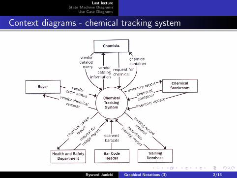
Context diagrams - chemical tracking system
Ryszard Janicki Graphical Notations (3) 2/18
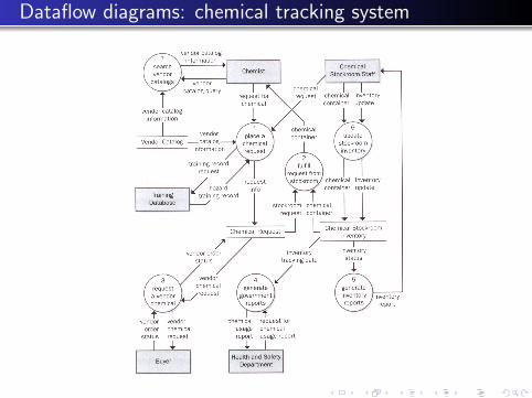
Dataflow diagrams: chemical tracking system
Last lectureState Machine Diagrams
Use Case Diagrams
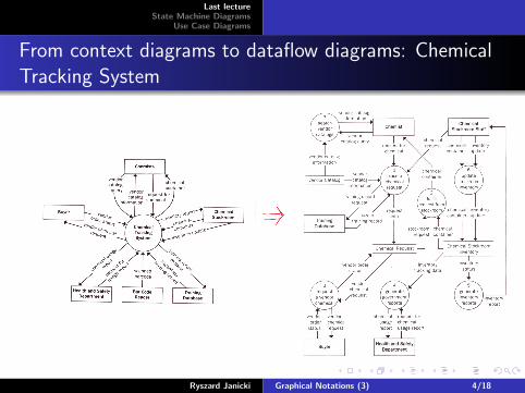
From context diagrams to dataflow diagrams: ChemicalTracking System
Ryszard Janicki Graphical Notations (3) 4/18
Last lectureState Machine Diagrams
Use Case Diagrams
Finite state machines, transition systems, finite automata
Capture the admissible behaviors of system components
Behavior of component instance = sequence of statetransitions for the items it controls
State Machine State = set of situations where a variablecharacterizing a controlled item has always the same value
- e.g. state MeetingScheduled : always same value for Date,Location (while other variable WithWhom on Meeting maychange value)
- Initial, final states = states where item appears, disappears- States may have some duration
State transition: caused by associated event
- if item in source state and event ev occurs then it gets totarget state
- Events are instantaneous phenomena
Ryszard Janicki Graphical Notations (3) 5/18
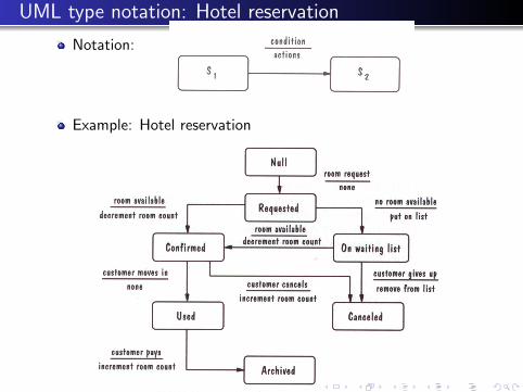
UML type notation: Hotel reservation
Notation:
Example: Hotel reservation
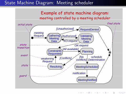
State Machine Diagram: Meeting scheduler
Example of state machine diagram:meeting controlled by a meeting schedulerg y g
[Unauthorized] RequestDenied
initial state final state
meetingRequest Gathering
MeetingData KO-request
ValidatingMeeting
Data
[Authorized]
OK-request
ConstraintsRequested
Planning[All available]
statetransition
[Noconflicts]
Requested[Conflicts]weakening
Requestschedule
Determination
state
event
notification
Resolving MeetingScheduledstate
guardMeetingNotified
g
Last lectureState Machine Diagrams
Use Case Diagrams
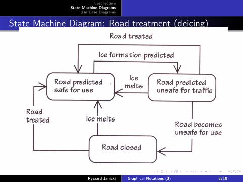
State Machine Diagram: Road treatment (deicing)
Ryszard Janicki Graphical Notations (3) 8/18

State Machine Diagram: Home security system (part of)

Chemical request in the Chemical Tracking System
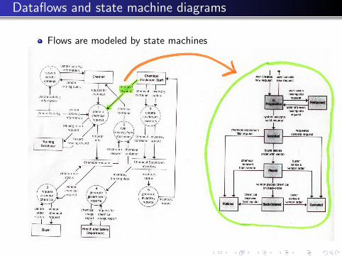
Dataflows and state machine diagrams
Flows are modeled by state machines
Last lectureState Machine Diagrams
Use Case Diagrams
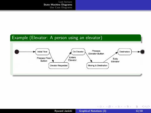
Example (Elevator: A person using an elevator)
Q6[5+5=10]
16
Ryszard Janicki Graphical Notations (3) 12/18
Last lectureState Machine Diagrams
Use Case Diagrams
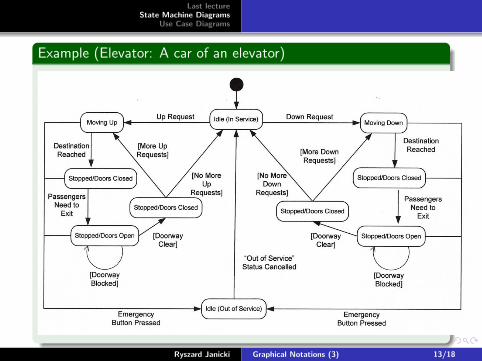
Example (Elevator: A car of an elevator)
Q6[5+5=10]
16
Ryszard Janicki Graphical Notations (3) 13/18

Last lectureState Machine Diagrams
Use Case Diagrams
System operations: use case Diagrams
Capture operations to be performed by a system componentand interactions with other components
- yet simpler, outline view ... but vague- to be made precise by annotations, interaction scenarios, etc.- introduced in UML to replace dataflow diagrams
Structuring mechanisms:
- <<include>>: to specify “suboperation”- <<extend>> + precondition: to specify “variant” operation
in exception case
Ryszard Janicki Graphical Notations (3) 14/18

Use case diagrams: scheduler
Use case diagram: example
operation interactionenvironment component
Check Request
Initiator <<extend>>Unauthorized
AskConstraints
CollectConstraints
ParticipantUnauthorized
Deny Requestvariant
operation
DetermineSchedule
C fli t<<include>>
MergeConstraints
R l
software component
Scheduler
ConflictResolver
ResolveConflictsParticipant
suboperation
operation performer
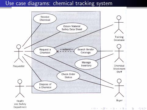
Use case diagrams: chemical tracking system

Use case diagrams: roads deicing
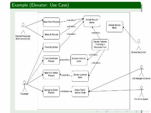
Example (Elevator: Use Case)
Q5[10]
Marking Scheme:
1) At least three types of user should be covered and well-described.
or
2) If you included Passenger/User and Site Manager/ Operator only, AND you
provided a very good use case diagram, also could be full-mark.
15