spe-121459-pp successful deployments of a new well ... successful deployments of a new well...
TRANSCRIPT
SPE-121459-PP
Successful Deployments of a New Well Intervention Methodology in Horizontal Wellbores (*) Henning Hansen, Ziebel, (*) Terje K. Wilberg, Ziebel, Kaj Stokkeland, Ziebel, (*) Peter T. Male, Petroleum Development Oman, and (*) Richard J. Kluth, Sensornet
(*) SPE Members Copyright 2009, Society of Petroleum Engineers This paper was prepared for presentation at the 2009 SPE/ICoTA Coiled Tubing and Well Intervention Conference and Exhibition held in The Woodlands, Texas, USA, 31 March–1 April 2009. This paper was selected for presentation by an SPE program committee following review of information contained in an abstract submitted by the author(s). Contents of the paper have not been reviewed by the Society of Petroleum Engineers and are subject to correction by the author(s). The material does not necessarily reflect any position of the Society of Petroleum Engineers, its officers, or members. Electronic reproduction, distribution, or storage of any part of this paper without the written consent of the Society of Petroleum Engineers is prohibited. Permission to reproduce in print is restricted to an abstract of not more than 300 words; illustrations may not be copied. The abstract must contain conspicuous acknowledgment of SPE copyright.
Abstract This paper describes and demonstrates how a patented new wellbore intervention solution can be deployed in long horizontal wells holding Fibre Optic Sensing devices including DTS (distributed temperature sensing), Point Pressure and Motion sensors performing logging services to evaluate the Inflow Performance along the reservoir sections. The paper also provides a description of the intervention system with a short introduction on how the final system emerged from the idea stage. Also, we provide two Case Histories - a horizontal oil producer with 2-phase flow, and horizontal water injector. The planning- and operational execution phases are briefly described. The paper closes with a brief conclusion of what has been achieved and what more this technology may be able to in the near future. The methodology describes can be seen as a 3
rd wellbore intervention method, in
addition to coiled tubing (CT) and wireline. Introduction Known technology today for accessing long reach horizontal wellbore sections to perform logging and remedial work typically requires coiled tubing or wireline “tractor”, where both these methods have constrains. Monitoring tools for use during fracturing and acid stimulation is also technology that is of limited availability (Ref SPE 106507). By adding Fibre Optic Sensing System to this technology we have been able to access horizontal wellbores for logging purposes demonstrating our capabilities to re-capture Inflow & Injection Performance evaluations similar to the today’s conventional methods for Cased Hole Logging Services, where these tools also are used for Flow Interpretations in open hole sections.
This paper describes the third well intervention
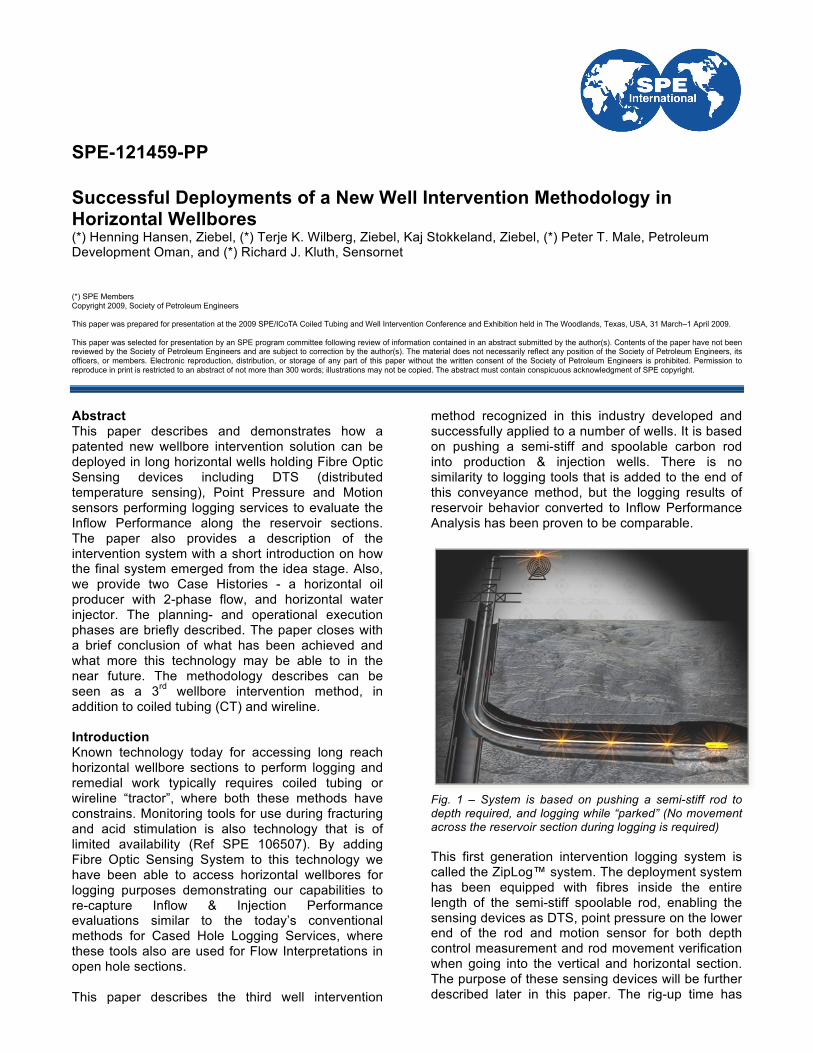
method recognized in this industry developed and successfully applied to a number of wells. It is based on pushing a semi-stiff and spoolable carbon rod into production & injection wells. There is no similarity to logging tools that is added to the end of this conveyance method, but the logging results of reservoir behavior converted to Inflow Performance Analysis has been proven to be comparable.
Fig. 1 – System is based on pushing a semi-stiff rod to depth required, and logging while “parked” (No movement across the reservoir section during logging is required)
This first generation intervention logging system is called the ZipLog™ system. The deployment system has been equipped with fibres inside the entire length of the semi-stiff spoolable rod, enabling the sensing devices as DTS, point pressure on the lower end of the rod and motion sensor for both depth control measurement and rod movement verification when going into the vertical and horizontal section. The purpose of these sensing devices will be further described later in this paper. The rig-up time has

2 SPE-121459-PP
been proven to be very efficient compared to conventional logging equipment. The complete system has been rigged up on an onshore facility in 2 hours according to the operations summary, where historical rig-up time was +24 hours. The Case Histories described in this paper demonstrates the unique value gathered by this new well intervention methodology, both with regards to operational issues and efficiency as well as the final data and interpretation results delivered, which was directly comparable to existing deployment technologies. The operational efficiency (downhole logging timing) was seen as very successful compared to existing deployment methods, and the total reach of the semi-stiff carbon “rod” traversed longer into the wells than other methods tried, gathering measurements resulting in further reservoir drainage understanding for the current Field Development Asset. Qualifying the Surface Equipment throughout the Research Development Project Background History The seed for the patent describing the deployment concept was born about 4 years back in time when a major operator in the E&P offshore business experienced difficulties in being able to perform DTS logging well interventions in their wells, due to the fact that the drilling rig was blocking 90% of the current well slots preventing traditional intervention system rig-up access to the wells during operations. The rig-up height between the rig and the well slots were too low (small) and prevented the operator from being able to rig up the standard lubricator and pressure control system required for wireline interventions. The frequency of logging the remaining 10% of the wells were not sufficient to enable sufficient reservoir surveillance to understand the well performance behavior. So the process of finding a solution started with immediate effect. The outcome of this resulted in a proposal, where a horizontally placed intervention lubricator with a bent section incorporated could be mounted on the wellhead. This enabled a semi-stiff spoolable “rod” to be pushed into the wells without any weight bars or similar required. As the wellheads were of the so-called horizontal type, a method to replace the two crown plugs within the x-mas tree using TFL (Through Flow Line pump down) technology was also presented.
Fig. 2 – Low rig-up height intervention concept, where valve illustrated at right would be connected to top of x-mas tree
Through discussions around the above-described method with this E&P operator and other operating companies, it was apparent that there was a significant need in general for an alternative well intervention method to overcome the described challenges. And keeping in mind that the proposed solution was an efficient and cost saving well intervention deployment system, we found that this method could also be used to go into conventional horizontal wellbore sections without rig-up height restrictions. A decision was made to develop this wellbore intervention system for work in horizontal wells to gain the proper experience and revenue. The surface deployment system The new well intervention solution developed comprises a injector mechanism pushing the rod into the well through the BOP with a pack-of sealing system above. The rod is guided through a “goose neck” from the spooling unit, where the rod is safely contained on the special made drum with break facilities.
Fig. 3 – The surface system rigged up on land well in Oman
The well control contains a remotely operated BOP system specially designed with a shear ram system able to cut the composite rod and/or seal against it as wells as a surface pack-off unit providing a
SPE-121459-PP 3
stuffing box seal against the rod. A control and monitoring package are used to operate the system and observe real-time data from the surface and downhole sensing systems. All surface units required for the intervention methodology are designed as small and compact as possible, where weights are kept to a minimum. The challenge was to ease transport and to overcome rig-up issues for both onshore and offshore facilities. The solution is unique in this matter, especially when mobilizing and rigging up the system on small offshore structures, where in some cases low crane capabilities and minimum deck space exist.
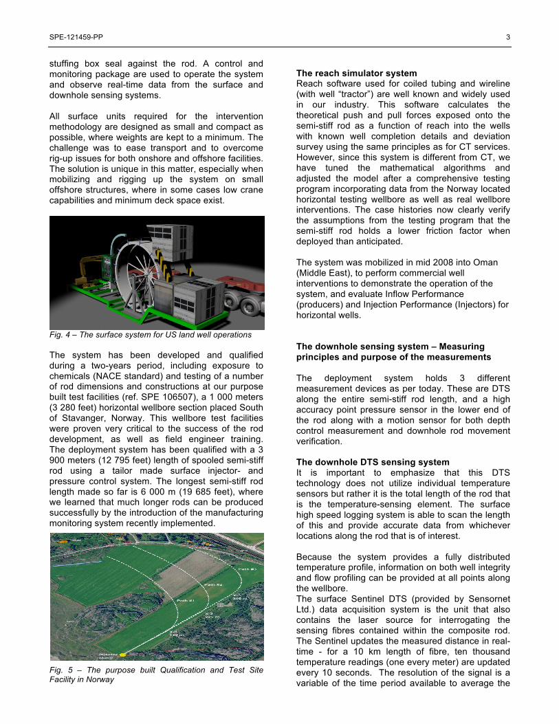
Fig. 4 – The surface system for US land well operations
The system has been developed and qualified during a two-years period, including exposure to chemicals (NACE standard) and testing of a number of rod dimensions and constructions at our purpose built test facilities (ref. SPE 106507), a 1 000 meters (3 280 feet) horizontal wellbore section placed South of Stavanger, Norway. This wellbore test facilities were proven very critical to the success of the rod development, as well as field engineer training. The deployment system has been qualified with a 3 900 meters (12 795 feet) length of spooled semi-stiff rod using a tailor made surface injector- and pressure control system. The longest semi-stiff rod length made so far is 6 000 m (19 685 feet), where we learned that much longer rods can be produced successfully by the introduction of the manufacturing monitoring system recently implemented. Fig. 5 – The purpose built Qualification and Test Site Facility in Norway
The reach simulator system Reach software used for coiled tubing and wireline (with well “tractor”) are well known and widely used in our industry. This software calculates the theoretical push and pull forces exposed onto the semi-stiff rod as a function of reach into the wells with known well completion details and deviation survey using the same principles as for CT services. However, since this system is different from CT, we have tuned the mathematical algorithms and adjusted the model after a comprehensive testing program incorporating data from the Norway located horizontal testing wellbore as well as real wellbore interventions. The case histories now clearly verify the assumptions from the testing program that the semi-stiff rod holds a lower friction factor when deployed than anticipated. The system was mobilized in mid 2008 into Oman (Middle East), to perform commercial well interventions to demonstrate the operation of the system, and evaluate Inflow Performance (producers) and Injection Performance (Injectors) for horizontal wells. The downhole sensing system – Measuring principles and purpose of the measurements The deployment system holds 3 different measurement devices as per today. These are DTS along the entire semi-stiff rod length, and a high accuracy point pressure sensor in the lower end of the rod along with a motion sensor for both depth control measurement and downhole rod movement verification. The downhole DTS sensing system It is important to emphasize that this DTS technology does not utilize individual temperature sensors but rather it is the total length of the rod that is the temperature-sensing element. The surface high speed logging system is able to scan the length of this and provide accurate data from whichever locations along the rod that is of interest. Because the system provides a fully distributed temperature profile, information on both well integrity and flow profiling can be provided at all points along the wellbore. The surface Sentinel DTS (provided by Sensornet Ltd.) data acquisition system is the unit that also contains the laser source for interrogating the sensing fibres contained within the composite rod. The Sentinel updates the measured distance in real-time - for a 10 km length of fibre, ten thousand temperature readings (one every meter) are updated every 10 seconds. The resolution of the signal is a variable of the time period available to average the

4 SPE-121459-PP
current signal. With further measurement time, a temperature resolution of <0.01°Celsius can be achieved. Both features are very important for monitoring the transient temperature changes used to identify flow changes, inflow performance and well integrity- and operational issues (tubing/liner leakage points, cross flow behind casing, valve conditions, gas lift valve operation, casing integrity, ESP temperature monitoring, etc). Reference is made to SPE 106507. The system can provide a measurement point every 0.5 meters (approx 1.5 feet) along the entire length of the intervention rod. It is the unique low resolution of the Temperature Data that allows modeling the temperature profile across the reservoir section to an Inflow Performance Curve related to well production and injection. It is important to emphasize that this DTS technology does not utilize individual temperature sensors but rather it is the total length of the rod that is the temperature-sensing element. The distributed nature of the measurements means that the DTS data provides accurate depth verification, so correlation of distinct temperature events with downhole features (perforations, gas lift valve operation, etc.,) is provided. The downhole pressure sensor system A high accuracy fiber optic pressure and temperature sensor has developed (by Ziebel) for downhole oilfield applications. The sensors are based on eccentric Fabry-Perot interferometer (EFPI), which allows precise measurement of an air gap (shown as “d” in the figure below). As pressure changes, the air gap also changes.
Fig. 6 – The downhole Fiber Optic Pressure Sensing element
EFPI-based sensors have several significant advantages over other fiber optic sensing technologies, such as calibrations and immunity to electro-magnetic interference (EMI). The sensor is embedded in the “bull nose” attached to the lower end of the semi-stiff rod.
The advantage of this measurement is real time monitoring of the pressure drawdown in production wells during the logging period to ensure that the well reaches steady-state conditions when the final DTS data are collected. If the downhole well conditions are not stabilized, the Inflow Performance evaluations will not reflect the correct well performance behavior. Furthermore, downhole pressure measurements can be used for monitoring
well tests, like Pressure Build-up (PBU) for Pressure Transient Analysis for production wells. The pressure sensor is also used to verify the vertical depth while RIH using the law of physics for gravity, fluid density and height difference to change absolute pressure measurements illustrated in the equation below: Pstatic fluid column = !*g*"h*cos (#),
Preservoir = Pwellhead + P static fluid column
The downhole motion sensor system A purpose built fiber optic motion sensor was developed and incorporated into the “bull nose”. This sensor will indicate movement or not of the lower end of the semi-stiff rod in the horizontal wellbore sections. In combination with the reach simulations for push and pull force, we can monitor movement in the horizontal section. This sensing also improves safety of the system, as it will in real time provide information avoiding insertion of the rod from surface if the “bull nose” is hung up downhole. Continuing such insertion could cause a failure of the rod. Depth Verifications When the intervention system was tested in the horizontal test wellbore commissioned, we learned that surface sensors measuring depth, weight of rod, etc., were not adequate to know if the bullnose was indeed moving forward downhole while pushing at surface. With the combination of using the monitoring devices and the surface panel for measuring the forces applied to push and pull the rod – and the fact that the semi-stiff rod is in a stiff position (not buckled) in the wellbore, we can verify how much length of the rod that is below the wellhead at any time. The pressure and motion monitoring allows us to verify when we are moving rod (RIH and POOH), and the reach simulations (push & pull forces) are used when we carry out pull tests during the RIH and POOH process. So from this, as well as the high-resolution surface depth measurement systems incorporated, the stiffness and more or less zero stretch of the rod, we have a very accurate depth control introduced.
SPE-121459-PP 5
Fig. 7 – DTS used for depth verification. The difference between the two curves is the distance of rod spooled into the well between the two DTS logs with wellhead as the accurate zero depth for this example.
These measuring devices have proven to provide clear indications of the measured depth of nipple profiles, tubing tail pipe and more. Inflow Performance Flow Allocations In general, the data measured from the DTS & point pressure can be used to understand the Inflow Performance from production- and injection wells. In general, Fig 8 illustrates how the continuous temperature profile may look like in a vertical well.
Fig. 8 – Temperature Anomalies from Inflow areas in the well bore The Flow Allocations are derived from using Energy material balance algorithms in combination with theory set forward by Curtis & Witherholt (ref SPE 4637).
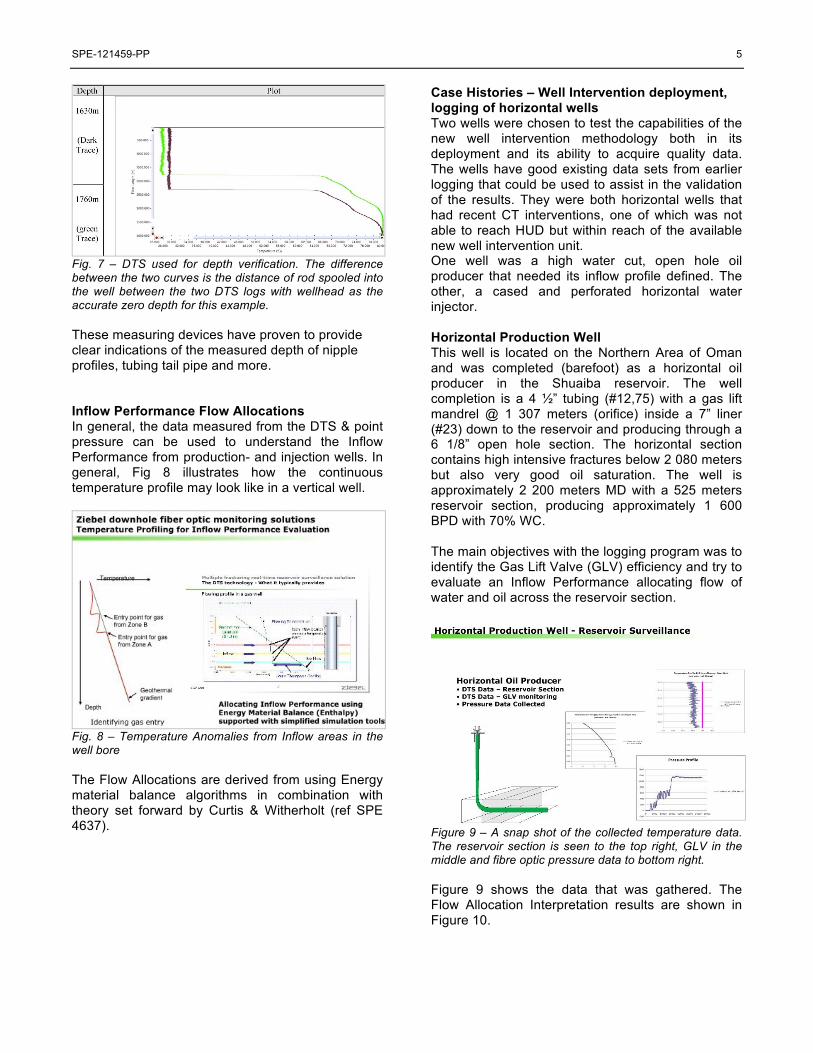
Case Histories – Well Intervention deployment, logging of horizontal wells Two wells were chosen to test the capabilities of the new well intervention methodology both in its deployment and its ability to acquire quality data. The wells have good existing data sets from earlier logging that could be used to assist in the validation of the results. They were both horizontal wells that had recent CT interventions, one of which was not able to reach HUD but within reach of the available new well intervention unit. One well was a high water cut, open hole oil producer that needed its inflow profile defined. The other, a cased and perforated horizontal water injector. Horizontal Production Well This well is located on the Northern Area of Oman and was completed (barefoot) as a horizontal oil producer in the Shuaiba reservoir. The well completion is a 4 !” tubing (#12,75) with a gas lift mandrel @ 1 307 meters (orifice) inside a 7” liner (#23) down to the reservoir and producing through a 6 1/8” open hole section. The horizontal section contains high intensive fractures below 2 080 meters but also very good oil saturation. The well is approximately 2 200 meters MD with a 525 meters reservoir section, producing approximately 1 600 BPD with 70% WC. The main objectives with the logging program was to identify the Gas Lift Valve (GLV) efficiency and try to evaluate an Inflow Performance allocating flow of water and oil across the reservoir section.
Figure 9 – A snap shot of the collected temperature data. The reservoir section is seen to the top right, GLV in the middle and fibre optic pressure data to bottom right.
Figure 9 shows the data that was gathered. The Flow Allocation Interpretation results are shown in Figure 10.

6 SPE-121459-PP
Figure 10 - Allocated flow rates versus the open hole log to verify depth
The SubSurface Asset Team has verified the results. The enclosed results are one of two sensitivities run for this well. The above illustrates where we obtained the best match on the simulated Temperature Profile versus the measured. Sensitivity run no. 2 is somewhat more conservative on the WC from Zone B, but both simulations clearly marks a water producing at Zone B. The survey also indicated cross-flow comparing the DTS data with SI and a flowing well. The well was only shut for a short period of time allowing for cross-flow to be observed. This observation was a major contributor to allocate the correct inflow areas across the horizontal wellbore, and to verify where the water was entering into the well. The monitoring of the GLV is presented in the following 3D graphic.
Fig 11 - Observation of GLV performance during flow period
This graph illustrates an instability over time leading to advising that (1) the orifice opening is too large for the flow rates of this well, or (2) the gas injection rate is to low.
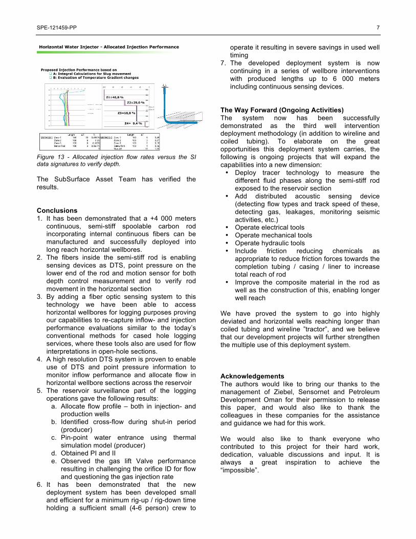
Horizontal Injection Well The well is located on the Northern Area of Oman and was completed (barefoot) as a cased and perforated horizontal water injector in the Shuiaba reservoir. The well completion is a 4 !” non-internal coated and 3 !” internal coated tubing string wedged through a 7” liner into the open hole section. The well is approximately 2 570 meters MD with a 900 m reservoir section, where the injected 60°C water is of rate of 12 000 BPD. The main objectives were to allocate the injection profile using DTS data from both warm-back effect and the transient heat changes from injecting hot water replacing the static wellbore fluid with a stable temperature from the SI period. The semi-stiff “rod” was able to get +207 m further into this well compared to previous coil tubing well intervention logging. The result is clearly shown in Figure 13, where we are able to allocate one specific area of injectivity. This is new information for the SubSurface Asset Team and helps to improve the understanding of the drainage efficiency in the Field.
Figure 12 – Snapshot of the collected temperature data. The top left and right shows SI data, while the bottom curve shows the transient effects changing temperature as stationary water is displaced by hot water injection.
Figure 12 above present the data that was gathered. The Flow (Injection) Allocation Interpretation results are shown in Figure 13.
SPE-121459-PP 7
Figure 13 - Allocated injection flow rates versus the SI data signatures to verify depth.
The SubSurface Asset Team has verified the results. Conclusions 1. It has been demonstrated that a +4 000 meters
continuous, semi-stiff spoolable carbon rod incorporating internal continuous fibers can be manufactured and successfully deployed into long reach horizontal wellbores.
2. The fibers inside the semi-stiff rod is enabling sensing devices as DTS, point pressure on the lower end of the rod and motion sensor for both depth control measurement and to verify rod movement in the horizontal section
3. By adding a fiber optic sensing system to this technology we have been able to access horizontal wellbores for logging purposes proving our capabilities to re-capture inflow- and injection performance evaluations similar to the today’s conventional methods for cased hole logging services, where these tools also are used for flow interpretations in open-hole sections.
4. A high resolution DTS system is proven to enable use of DTS and point pressure information to monitor inflow performance and allocate flow in horizontal wellbore sections across the reservoir
5. The reservoir surveillance part of the logging operations gave the following results:
a. Allocate flow profile – both in injection- and production wells
b. Identified cross-flow during shut-in period (producer)
c. Pin-point water entrance using thermal simulation model (producer)
d. Obtained PI and II e. Observed the gas lift Valve performance
resulting in challenging the orifice ID for flow and questioning the gas injection rate
6. It has been demonstrated that the new deployment system has been developed small and efficient for a minimum rig-up / rig-down time holding a sufficient small (4-6 person) crew to
operate it resulting in severe savings in used well timing
7. The developed deployment system is now continuing in a series of wellbore interventions with produced lengths up to 6 000 meters including continuous sensing devices.
The Way Forward (Ongoing Activities) The system now has been successfully demonstrated as the third well intervention deployment methodology (in addition to wireline and coiled tubing). To elaborate on the great opportunities this deployment system carries, the following is ongoing projects that will expand the capabilities into a new dimension: • Deploy tracer technology to measure the
different fluid phases along the semi-stiff rod exposed to the reservoir section
• Add distributed acoustic sensing device (detecting flow types and track speed of these, detecting gas, leakages, monitoring seismic activities, etc.)
• Operate electrical tools • Operate mechanical tools • Operate hydraulic tools • Include friction reducing chemicals as
appropriate to reduce friction forces towards the completion tubing / casing / liner to increase total reach of rod
• Improve the composite material in the rod as well as the construction of this, enabling longer well reach
We have proved the system to go into highly deviated and horizontal wells reaching longer than coiled tubing and wireline ”tractor”, and we believe that our development projects will further strengthen the multiple use of this deployment system. Acknowledgements The authors would like to bring our thanks to the management of Ziebel, Sensornet and Petroleum Development Oman for their permission to release this paper, and would also like to thank the colleagues in these companies for the assistance and guidance we had for this work. We would also like to thank everyone who contributed to this project for their hard work, dedication, valuable discussions and input. It is always a great inspiration to achieve the “impossible”.

8 SPE-121459-PP
References 1. H. Hansen, T. Wilberg, G. Naldrett and N.
Meldrum, “Semi-stiff Carbon-Fiber Rod Pushed into Live Wells for Reservoir Performance Monitoring and Leakage Detection”, SPE 106507
2. Curtis, M. A. and Witterholt, E.J “Use Of The Temperature Log For Determining The Flow Rates In Producing Wells”, SPE 4637
3. Lenn C, Kuchuk F, Rounce J and Hook P: “Horizontal Well Performance Evaluation and Fluid Entry Mechanisms” SPE 49089
Nomenclature
PI Productivity index II Injectivity index SI Shut in BPD Barrels per day CT Coiled tubing MD Measured depth WC Water cut m Meters