space suit development for orion
TRANSCRIPT

48th International Conference on Environmental Systems ICES-2018-199 8-12 July 2018, Albuquerque, New Mexico
Copyright © 2018 David Clark Company, Incorporated
Space Suit Development for Orion
Shane E. Jacobs1 and Donald B. Tufts2 David Clark Company Incorporated, Worcester, MA, 01604
Dustin M. Gohmert3 Johnson Space Center, Houston, TX, 77058
This paper describes the recent design and development of a launch/entry and contingency space suit for NASA’s Orion spacecraft. The suit is designed to be worn during launch, ascent, and entry, to protect crewmembers from a variety of hazards and contingencies, most notably cabin depressurization. The paper details design efforts to improve shoulder and elbow mobility. Additionally, structural design activities are presented- including multiple rounds of analysis and testing – to ensure significant margins of safety when the suit is pressurized to 8 psid. Two new suits with the latest design features were built and human-tested in multiple vacuum chamber tests, which are described.
Nomenclature ACES = Advanced Crew Escape Suit CCA = Communications Carrier Assembly DCCI = David Clark Company Incorporated DSC = Dual Suit Controller ECLSS = Environmental Control and Life Support System EVA = Extravehicular Activity LCG = Liquid Cooling Garment OCSS = Orion Crew Survival System ppCO2 = partial pressure of carbon dioxide psia = pounds per square inch absolute psid = pounds per square inch differential sccm = standard cubic centimeters per minute VPIST2 = Vacuum Pressure Integrated Suit Test 2
I. Introduction HE Orion spacecraft is NASA’s next generation exploration spacecraft. It is designed to transport astronauts to lunar orbit and other destinations beyond Low Earth Orbit. It will nominally carry four crewmembers,
transporting them through launch, ascent, travel through deep space, and reentry back to Earth, with a design mission length of 21 days or greater. Due to the unique requirements of this vehicle and mission, a new launch/entry and contingency space suit was required for Orion. The suit is required to not only protect the crew in the event of short term cabin depressurization emergencies during dynamic phases of flight (launch and landing), but also for deep space contingencies that would require the crew to seek safe haven in the suit during transit back to Earth. This key requirement – long duration survival – is the primary design driver that significantly differentiates this suit from conventional launch/entry suits, or short duration Extravehicular Activity (EVA) suits. David Clark Company Incorporated and NASA have worked together to design and develop this new space suit, part of the Orion Crew Survival System (OCSS). The new suit is termed the S1041 OCSS Suit. The S1041 OCSS Suit evolved from the S1035 [1] Advanced Crew Escape Suit (ACES) worn during the second half of the space shuttle program. While many features of the S1035 ACES have been preserved, most have been
1 Softgoods Design Manager, Research and Development, 360 Franklin St. Worcester, MA 01604 2 Program Manager, Research and Development, 360 Franklin St. Worcester, MA 01604 3 OCSS Program Manager, Johnson Space Center, 2101 NASA Parkway, Houston, TX 77058
T

International Conference on Environmental Systems
2
redesigned due to new requirements driven by Orion’s operational concepts. For example, the suit is designed to function at an operational manned pressure of 8 psid (the S1035 ACES was designed to an operational requirement of 3.5 psid), and works within Orion’s closed loop, continuous flow Environmental Control and Life Support System (ECLSS) architecture (whereas the S1035 ACES was open loop, demand based). The S1041 OCSS Suit ensemble consists of the coverall, helmet, gloves, footwear and a variety of ancillary equipment. This paper focuses on the coverall. Ongoing design efforts for gloves, helmet, footwear and many other subsystems will be presented in future papers. A new neck seal and gas inlet assembly have been designed, which ensure efficient CO2 washout and allows crewmembers to close the neck seal for contingency water egress operations upon landing. Higher mobility elbows and shoulders have been incorporated to provide crewmembers with much improved two-handed work envelope mobility. Structural analysis and testing have driven new designs and materials in much of the restraint layer. In the following sections, the key driving requirements are outlined, which drove suit architecture and critical design trades. The core architecture is outlined, and the details of each design element are discussed. The design work led up to a series of vacuum chamber tests, which are discussed. Finally, future work and plans are outlined as development activities continue towards the pursuit of the first manned test flight of Orion.
II. Suit Requirements The requirements for the OCSS Suit consist of those specific to the Orion vehicle and operations, and those
generic to launch and entry suits and spaceflight hardware for maintaining a minimum survivability and crew safety capability. In general, all requirements are either directly from NASA or derived collaboratively by NASA and DCCI.
The Orion vehicle-specific requirements are being developed in tandem with those for complementary subsystems. This allows for subject matter experts to negotiate and effectively allocate the physical and functional requirements to best support cross-subsystem integration and mission concept of operations. The key driving requirements are paraphrased and listed in Table 1 below. It should be noted that many of the suit requirements continue to evolve as complementary subsystems mature. Therefore many of these are better categorized as design goals rather than strict requirements.
Table 1. Suit Driving Requirements/Design Goals Number Requirement Description
1 Suit Pressure The Suit shall operate at 4.3 psia/psid for long duration contingency operations, and at 8 psia/psid for shorter durations
2 Suit ppCO2 Level The suit must maintain the inhaled partial pressure of carbon dioxide in the oral nasal region at or below acceptable limits.
3 Pressure Drop The suit shall have minimal pressure drop to the extent possible. 4 Unassisted Suit
Donning/Doffing The Suit shall be donnable and doffable by an unassisted crew member.
5 Anthropometric Dimensions and Sizing
The Suit shall accommodate the full anthropometric range from the 1st percentile female to the 99th percentile male.
6 Long-duration Pressurized Operations
The suit shall operate pressurized at 4.3 psia, in a vacuum, for a period of 144 hours
7 Mobility The Suit shall provide significant pressurized mobility in the two-handed work envelope at 4.3 psid
8 Pressurized Environment
The Suit shall comply with the applicable performance requirements during and after exposure to oxygen environments of 30% and 100%
9 Minimum Operational Loads
The Suit hardware shall be operable by all crewmembers
10 Crew Extraction The Suit shall provide handles, an internal harness, and other crew extraction aids/features
To fully understand the genesis of the long-duration pressurized requirement noted above, it is important to
understand Orion’s contingency depressurized cabin operations concepts. Orion’s mission profile places it at certain mission points of limited return – up to 144 hours away from Earth. Orion nominally operates at 14.7 psia with a

International Conference on Environmental Systems
3
normal 80/20 mix of nitrogen and oxygen, respectively. In the event of a cabin depressurization, the Orion capsule is capable of feeding a 0.25-in. hole for 1 hour while maintaining a minimum 8.0 psia cabin pressure. During this 1-hour interim period, the crew would don the OCSS suit ensemble with all ancillary gear required for long duration survival. To minimize risk of decompression sickness, the OCSS suit will be initially held at 8.0 psia for a period of approximately 9 hours. This allows sufficient time for the suit loop to enrich to greater than 95% oxygen within the first hour and for denitrogenation of the crew during the remaining time. Upon completion of this denitrogenation period, the crew will reduce the suit operational pressure to 4.3 psia. This protocol leverages thousands of hours of historical performance data gathered by NASA in the Extravehicular Mobility Unit to ensure crew safety through minimizing adverse physiological reactions. The crew would remain at 4.3 psia for the duration of the depressurization event until return home. While mobility requirements would be minimal during the initial 8.0 psia denitrogenation phase, the crew will be required to eat, drink, sleep, and generally live within the suits at 4.3 psia for the balance of the 6 day duration.
III. Design Overview After a comprehensive review of the requirements and concept of operations, and based on lessons learned from
years of suit design, development, test and evaluation activities [2-5], the baseline suit architecture was established. The primary focus of the design effort for the coverall was to preserve unpressurized comfort, mobility and crew survivability, while meeting the challenges associate to 8 psia/psid (assuming the cabin has been completely evacuated to vacuum, the absolute pressure inside the suit of 8 psia will yield an equivalent differential pressure of 8 psid. Both are important, as the differential pressure drives the structural loading of the suit, while the absolute pressure drives mass flow requirements, communications, etc.) and 144 hour contingency requirements. These two goals required delicate balance, as typically efforts to satisfy the pressurized requirements compromise performance in the unpressurized mode. It was imperative that the suit be as lightweight and low bulk as possible, while maintaining capability in a significantly elevated pressure regime.
Each component of the OCSS coverall is described in detail in this section. The details of the design and the analyses and development testing that were performed that drove the design decisions are described for each element. Satisfaction of key requirements for each element are demonstrated at this early development phase. Future work will be performed to demonstrate full requirement verification.
A. Core Architecture The S1041 OCSS suit is a single volume, closed-loop, continuous flow, full pressure suit. It has a gas inlet and
gas outlet, both located on the front lower torso, which connect to the umbilicals to exchange gases with the closed-loop ECLSS. The suits are isolated on their own loop from the cabin [6]. Gas is routed from the blue air-inlet connector (left abdomen as worn), internal to the suit, to the oral-nasal region through a neck-seal and gas inlet assembly. This constant-rate gas flow provides fresh oxygen, and removes CO2, heat and moisture as it flows back out. The suit has a two-layer pressure garment, and a fire-retardant exterior cover. A communication pass through on the right leg of the suit provides connections from the Audio Interface Unit to the Communications Carrier Assembly (CCA). Wrist disconnects provide the interface to the gloves and a bearing at the wrist, while a suit-to-helmet disconnect provides the interface to the helmet. A Dual Suit Controller (DSC) is worn on the left (as worn) thigh, and a pass through for the Liquid Cooling Garment (LCG) is on the right thigh. The DSC is primarily used for contingency scenarios, when the suit is no longer connected to the closed-loop ECLSS. A valve to allow evacuation of urine is located on the inner left thigh. Footwear are worn external to the pressure garment. Ongoing footwear, glove, helmet, LCG and CCA design efforts remain in progress but are beyond the scope of this paper.
With the core architecture established, several development units were fabricated and extensively tested. Modifications were made throughout the design process as designers fine-tuned each design element to meet requirements. Development testing is critical for space suit design. It is imperative to develop prototypes as early as possible and obtain subjective feedback as well as perform quantitative testing on items such as pressure drop. Photos from development testing are shown in Figure 1.

International Conference on Environmental Systems
4
Figure 1. S1041 OCSS Suit Prototype. Unpressurized, at 4.3 PSID, and at 1 psid vent pressure
B. Pressure Garment The pressure garment, shown in Figure 2, is primarily two layers – an inner gas container layer, and a high-
strength, low-elongation restraint layer. The inner layer of the pressure garment is made of a selectively permeable material, such that it allows some water vapor to transmit out of the suit, while remaining impermeable to oxygen and nitrogen. This material greatly reduces the thermal burden of the suit, working in tandem with the LCG to maintain core body temperature at acceptable levels. This air-tight layer also includes integrated boots, which maintain the pressure integrity of the suit underneath the separable footwear. A very low allowable leak rate is required of the pressure garment, driven by the closed-loop ECLSS architecture. Development pressure garment units have demonstrated leakage rates less than 100 sccm as measured in laboratory settings.
The restraint layer is made of high-strength, low-elongation materials, designed to accommodate the structural pressure loads, and patterned to provide mobility and comfort. Structural analysis and testing specific to the restraint layer is discussed in the next section. The restraint layer incorporates resizing above and below the elbows, and above and below the knees. This resizing is especially critical during the development phase, as multiple subjects use and evaluate a select few prototypes. The long-term plan is to design and build custom suits for each crewmember, so sizing adjustments in the final flights units will be reduced, but not eliminated, as some small sizing refinements are anticipated, even for custom suits.
The long duration pressurized operations requirement drives the need for a high degree of precision sizing, so as to provide near perfect sizing accommodations for each crewmember. To avoid short term discomfort which evolves to long term intolerability, all bodily segments must be uniquely tailored to the individual with virtually no misalignment. This degree of accommodation has led to the logistics case to provide each crewmember with a true custom fit suit, which also incorporates the ability to fine tune the suit to the individual as worn pressurized. This approach allows the garment to adapt to and overcome any variability in softgoods manufacturing as well as intangible human anatomical variations in multiple environments.

International Conference on Environmental Systems
5
Figure 2. Pressure Garment
The pressure garment is donned through the main-entry pressure sealing closure, an air-tight, water-tight slide
fastener. This main-entry closure runs vertically along the back of the suit. Unlike the S1035 ACES, which incorporates a single slide fastener at this opening, the S1041 OCSS suit incorporates a second restraint slide fastener, which bears the significant pressure loads. This additional closure was driven by the 8 psid requirement, which when coupled with the required safety factors for proof and ultimate pressure testing, drove the hoop stresses beyond the capabilities of the single pressure sealing closure. This approach is similar to that employed in the S1030A Ejection Escape Suits, flown on the first four Space Shuttle missions. Careful design must be employed to ensure this configuration remains comfortable in a recumbent posture for long durations.
The legs are patterned to pressurize in the seated posture, such that the hips and knees are flexed in their neutral position. The pressure garment includes mobility features designed into the shoulders and elbows. The two-handed work envelope mobility requirement drove significant design efforts, to maximize pressurized mobility in the elbows and shoulders, without hindering unpressurized comfort nor greatly increasing risk of injury during landing. Options such as upper arm bearings have been explored [7, 8], but ultimately after extensive effort, entirely soft mobility joints were shown to provide sufficient two-handed work envelope mobility. The shoulders employ link-net – a unique material fabricated from cord, developed by DCCI – patterned in a unique way for this application. The elbows are tucked fabric, with very low-elongation webbings integrated along the sides of the joint. This construction of elbow has previously been shown to be very high mobility and low torque [4]. The elbow design recently passed a cycle test at 4.3 psid to 150,000 flexion/extension cycles followed by 80,000 flexion/extension cycles at 8 psid.

International Conference on Environmental Systems
6
Figure 3. Prototype elbow during cycle testing
C. Exterior Cover A fire retardant exterior cover is incorporated to the outside of the pressure garment, protecting the restraint layer
and incorporating crew extraction handles coupled to an internal harness, flotation interfaces, pockets, channels for routing of the emergency air hoses, and patches. The exterior cover is patterned to provide unrestricted mobility unpressurized, and to not further restrict pressurized mobility (as controlled by the restraint layer), while minimizing bulk and thermal burden to the extent possible. It incorporates a tucked fabric feature in the shoulders, which enables overhead reach unpressurized or at vent pressure, far greater than that of legacy pressure suits. The exterior cover includes pockets for items such as the pass throughs (communications, LCG, DSC and urine) and for crew survival gear. It is designed to minimize snag hazards. The exterior covers shown in Figure 4 do not include the full suite of design features.
Figure 4. Exterior Cover

International Conference on Environmental Systems
7
D. Gas Inlet and Outlet Connectors The gas inlet and outlet connectors allow the crewmember to quickly attach the umbilical to the suit at the
abdomen. The gas inlet connector directs the incoming gas to the internal neck seal and gas inlet assembly. Gas flows out the gas outlet connector at the right (as worn) abdomen. The connectors can be mated to the umbilical by simply pushing the umbilical connector into the suit side connector. It is demated by pulling up on two spring-loaded tabs, and rotating the upper half of the suit side connector. The connectors are a slightly modified design of those used in the Apollo program, leveraging years of operational experience.
Initially, a single “ganged” connector that allowed for gas inlet and exhaust with a single connection was explored. Due to anthropometric placement restrictions coupled with seated access volume restrictions, this concept ultimately was deemed sub-optimal, as shrinking volumes further increased pressure drop. To accommodate limited real estate, especially on the first percentile female suit, the lower outboard abdomen was chosen as the gas connector mounting area. Splitting the connectors such that a single connector served only one flow path allowed for fitment of the connectors in an area of the body that was 1) close to the end users head without complex internal suit routing, 2) placement outboard of the seatbelts to prevent blunt force injury during seated acceleration events, and 3) operable seated reach and access for emergency egress removal. As seated, the Orion gas umbilicals would route to the outboard side of the body (left for port seated crew, right for starboard seated crew) and pass over the abdomen to their respective connectors. The inlet gas connector mates to the inlet gas assembly as described below. The exhaust gas connector is mated to an internal spacer that prevents occlusion of air flow during gas return.
Both sides of the connectors are self-sealing – the suit side self-seals to prevent smoke or other toxic gases from entering the suit, should a crewmember be disconnected from the supply during an emergency egress. This feature also prevents water from entering the suit during a contingency water egress.
E. Neck Seal and Gas Inlet Assembly The neck seal and gas inlet assembly is a unique new sub-assembly. The neck seal component has three
operating modes – completely open, mostly closed, and fully closed. It is designed to be nominally open, such that it is not tight to the crewmember’s neck. During nominal operations, the suit is entirely one volume, so the neck seal remains undeployed. This serves to optimize crew comfort, and reduce pressure drop. The second mode for the neck seal is for the 144 hour contingency case, in which the suit will remain one volume, and the neck seal won’t be cinched tight to the crewmember’s neck, but it will be closed slightly so as to create a distinct downward flow of gas while similarly minimizing pressure drop. This mode is intended to prevent any waste that is not properly captured by the waste management system from floating up into the crewmember’s oral nasal region. Finally, for contingency water egress, the neck seal will be deployed tight to the crewmember’s neck, to prevent water from entering the suit.
The assembly also incorporates a channel that routes the incoming gas from the gas inlet connector to the oral nasal region. It is clamped to a snout on the inside of the gas inlet connector, and integrated at the other end to the neck seal. It employs a crush and kink-proof material, to ensure the gas flow path cannot be blocked or restricted by tightening of the seat restraints or otherwise. This assembly ensures efficient CO2 washout as the cleanest gas is always flowing directly to the oral nasal region. Multiple configurations of this channel have been tested, with the final design demonstrating the most efficient CO2 washout, best manufacturability, lowest pressure drop, and least impingement on the neck opening to optimize donning/doffing.
While seemingly simple in design, the configuration of the neck seal and gas inlet assembly was the result of several years of study spanning many considerations. The primary benefit of this somewhat unconventional design is that it provides directly impinging flow into the oral-nasal region, rather than diffuse flow emanating from the rear of the helmet typical of other space suit designs. This disruption of the exhaled gas evident with the OCSS design effectively displaces the exhaled CO2 bullous with significantly less gas flow than diffuse flow systems. This efficiency allows Orion’s ECLSS fans to run at lower speeds to perform sufficient CO2 removal, thereby increasing overall ECLSS efficiency.
To further increase efficiency, the cross sectional area of the inlet flow path is never reduced as it passes from vehicle to suited occupant. That is, the cross sectional area of flow presented in the umbilical allows gas to flow through the inlet fitting to the neck seal delivery orifice without any major head losses due to flow path constriction.
Finally, the routing of the incoming gases directly from the left abdomen to the neck seal area was intentionally chosen to be the shortest possible path, thereby minimizing internal head loss due to turbulence from anti-crush features. This direct path also precludes the need to route the gas around the back of the neck adjacent to the neck ring, which would have presented a significant integration challenge with the vehicle’s 5-point harness shoulder belts when in the seated posture.

International Conference on Environmental Systems
8
F. Communications Pass Through A pass through for the communications system is located on the right (as worn) leg. The pass through is
anodized aluminum, and the wires are hermetically sealed. External to the suit, a quick disconnect is attached to a short length of cable, to minimize snag hazards when disconnected, but allow for mating/demating operations with a gloved hand. Internal to the suit, the cable is routed up to the neck area, where the crewmember can mate the CCA with a quick disconnect. The mated connector can then be tucked into the front of the suit such that it lies parallel with the gas inlet duct, ensuring crewmember comfort.
G. Dual Suit Controller The Dual Suit Controller (DSC), which has been used in numerous other applications, is employed in the S1041
but in a very unique manner. In many other applications such as the S1035 ACES, the controller is worn on the torso of the suit, where it operates in both nominal and contingency modes. In these applications, under nominal operations, the controller maintains only a slight back pressure within the suit, and vents excess gas into the ambient (cabin) environment. In the event of a cabin depressurization, the controller automatically maintains the crewmember at the minimum absolute pressure environment.
For the S1041 OCSS, the DSC is worn on the right (as worn) leg of the suit, as opposed to the typical location on the torso, and it is only used in contingency scenarios when the suit is disconnected from Orion’s closed-loop ECLSS, and the suits are operating with the emergency O2 bottles.
H. Other components The pass throughs for urine relief/removal and for the LCG are each undergoing significant redesign activities,
the details of which will be described in future papers. Similarly, legacy hold-down assembly (the system of cables and pulleys that control torso length) and counter-balance springs (the system that off-loads helmet weight onto the shoulders when upright) have been used for development testing, but are currently being redesigned, so are not discussed herein.
The wrist disconnects are a legacy design and are unchanged from those used in the S1035 ACES. The suit-to-helmet disconnect is a minor redesign of the S1035 version – the cross section has been made much smaller, and two different sizes have been designed, to mate with the two new sizes of helmet.
IV. Structural Testing The 8 psid requirement, coupled with the 144 hour pressurized contingency requirement, and the required safety factors for proof and ultimate pressure testing, dictated that the suit need to withstand a 15 minute, 17 psid test. While NASA Structural Design Verification Requirements (SDVR, NASA-STD-5016) require pressure suits to be tested to 1.5 times maximum allowed working pressure, it was determined that the enhanced safety factor resulting from a 17 psid test provided additional margin against otherwise unquantifiable manned loading while in use. Testing a suit unmanned, to twice the expected manned operating pressure, is typical for space suit development. For example, Figure 5 shows an OCSS suit being tested unmanned at 8.6 psid, prior to a 4.3 psid manned test.

International Conference on Environmental Systems
9
Figure 5. Structural testing at 8.6 psid
The 17 psid test presented a difficult challenge, as this pressure level is well above traditional launch/entry suit pressure regimes. Several rounds of tests and analyses were required. Multiple development units were manufactured and tested at elevated pressures. Figure 6 shows data from a burst test of an early development unit, which failed at 15.1 psid. This testing provided a baseline and drove further testing and analysis.
Figure 6. Test data from burst test of initial suit configuration. This suit burst at 15.1 psid
Material samples were pull-tested and test bags were tested to failure, to determine the material strength and
elongation when utilized in the restraint layer configuration. Structural test bags were designed, manufactured and tested extensively. The bags were designed to include key interfaces, materials, stitching configurations and

International Conference on Environmental Systems
10
geometries similar to that of the suit, but are greatly simplified to reduce build times as compared to an entire suit. Bags were made with various candidate materials to test them in similar loading condition as that of a pressurized suit. Materials in two ply configurations and various warp/fill/bias configurations were also tested. An example of the test bag is shown in Figure 7 and example test data from a burst test shown in Figure 8.
Figure 7. Examples of structural test bags
Ultimately, based on all of the test data and analyses, the optimal materials, stitching and seam configurations
were selected and a development suit was fabricated incorporating same. The suit was subjected to a 15 minute 17 psid test, which it successfully passed (data shown in Figure 9). This test provides excellent confidence for future suit testing at elevated pressures and for long duration pressurized tests.

International Conference on Environmental Systems
11
Figure 8. Example of test data from burst test of structural test bag. This configuration burst at 37.5 psid
Figure 9. Successful 15 minute test of final pressure garment configuration at 17 psid
International Conference on Environmental Systems
12
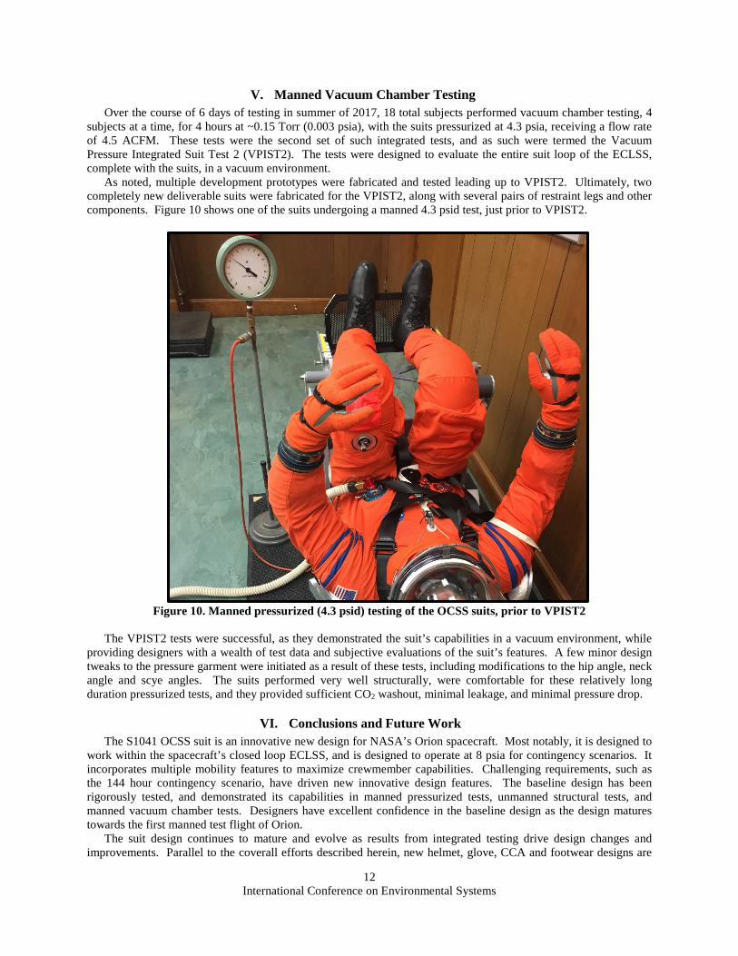
V. Manned Vacuum Chamber Testing Over the course of 6 days of testing in summer of 2017, 18 total subjects performed vacuum chamber testing, 4
subjects at a time, for 4 hours at ~0.15 Torr (0.003 psia), with the suits pressurized at 4.3 psia, receiving a flow rate of 4.5 ACFM. These tests were the second set of such integrated tests, and as such were termed the Vacuum Pressure Integrated Suit Test 2 (VPIST2). The tests were designed to evaluate the entire suit loop of the ECLSS, complete with the suits, in a vacuum environment.
As noted, multiple development prototypes were fabricated and tested leading up to VPIST2. Ultimately, two completely new deliverable suits were fabricated for the VPIST2, along with several pairs of restraint legs and other components. Figure 10 shows one of the suits undergoing a manned 4.3 psid test, just prior to VPIST2.
Figure 10. Manned pressurized (4.3 psid) testing of the OCSS suits, prior to VPIST2
The VPIST2 tests were successful, as they demonstrated the suit’s capabilities in a vacuum environment, while
providing designers with a wealth of test data and subjective evaluations of the suit’s features. A few minor design tweaks to the pressure garment were initiated as a result of these tests, including modifications to the hip angle, neck angle and scye angles. The suits performed very well structurally, were comfortable for these relatively long duration pressurized tests, and they provided sufficient CO2 washout, minimal leakage, and minimal pressure drop.
VI. Conclusions and Future Work The S1041 OCSS suit is an innovative new design for NASA’s Orion spacecraft. Most notably, it is designed to
work within the spacecraft’s closed loop ECLSS, and is designed to operate at 8 psia for contingency scenarios. It incorporates multiple mobility features to maximize crewmember capabilities. Challenging requirements, such as the 144 hour contingency scenario, have driven new innovative design features. The baseline design has been rigorously tested, and demonstrated its capabilities in manned pressurized tests, unmanned structural tests, and manned vacuum chamber tests. Designers have excellent confidence in the baseline design as the design matures towards the first manned test flight of Orion.
The suit design continues to mature and evolve as results from integrated testing drive design changes and improvements. Parallel to the coverall efforts described herein, new helmet, glove, CCA and footwear designs are
International Conference on Environmental Systems
13
maturing and undergoing development testing. Suits with all of these integrated components will be developed and subjected to sled testing, integrated crew survival testing, and further vacuum chamber tests. The suit design will be subjected to a rigorous qualification test program, prior to flying on the Orion spacecraft.
Acknowledgments The authors would like to thank NASA for funding the development of the OCSS suit through the Orion
program. Thanks to Philip Hooper for his dedication to this project. Thanks also to the team of David Clark employees and NASA colleagues for all of your valuable inputs into the suit design, and for supporting this paper.
References 1. Barry, D.M., Bassick, J.W. “NASA Space Shuttle Advanced Crew Escape Suit Development.” 25th International Conference
on Environmental Systems, July, 1995. SAE 951545 2. Jacobs, S.E., Barry, D.M., McCarter, D.R., Todd, M.V., “Pressure Suit Design for High-Altitude Bailout: Lessons Learned
from Red Bull Stratos” 43rd International Conference on Environmental Systems, July, 2013. AIAA 2013-3398. 3. Jacobs, S.E, Tufts, D.B, “Follow-On Development of the Demonstrator Suit for Post-Shuttle Operations” 41st International
Conference on Environmental Systems, July, 2011. AIAA 2011-5030 4. Jacobs, S.E., Tufts, D.B., “Space Suit Development for the Multi-Purpose Crew Vehicle” 42nd International Conference on
Environmental Systems, July, 2012. AIAA 2012-3550 5. Stroud, K.J., Jacobs, S.E., “Dream Chaser Integrated Spacecraft and Pressure Suit Design”. 45th International Conference on
Environmental Systems, July, 2015. 2015-ICES-117 6. Stambaugh, I., Conger, B., Eckhardt, B. “Orion Environmental Control and Life Support Systems Suit Loop and Pressure
Control Analysis” 45th International Conference on Environmental Systems, July, 2015. 2015-ICES-148 7. Watson, R.D., “Modified Advanced Crew Escape Suit Intravehicular Activity Suit for Extravehicular Activity Mobility
Evaluations” ” 44th International Conference on Environmental Systems, July, 2014. 2014-ICES-194 8. Bowie, J.T., et al., “Asteroid Redirect Crewed Mission Space Suit and EVA System Maturation” 45th International Conference
on Environmental Systems, July, 2015. 2015-ICES-343