space storable rocket technology program · space storable rocket technology program ssrt final...
TRANSCRIPT

NASA CONTRACTOR REPORT 189131
SPACE STORABLE
ROCKET TECHNOLOGY PROGRAM
SSRT
FINAL REPORT - BASIC PROGRAM
MAY1992
Prepared for:
NASA-LeRC
Cleveland, Ohio 44135
Contract NAS 3-26246
Prepared by:
M.L. Chazen, T. Mueller, A.R. Casillas, D. Huang
TRW Applied Technology Division
Redondo Beach, California 90278
Approval:
Melvin Chazen _/Program Manager
Albert So|bes, Manager
Combustion and Energy Toehnology Department
±
https://ntrs.nasa.gov/search.jsp?R=19920016362 2018-06-22T11:44:10+00:00Z
TABLE OF CONTENTS
1.0 Summary ..........................................
2.0 Introduction .....................................
3.0 Applications Evaluation ..........................
3.1
3.2
3.3
3.4
3.5
Missions ....................................
System Analyses .............................Fuels Evaluation ............................
System Requirements .........................
Applications Evaluation Conclusions .........
4.0 Analyses .........................................
4.1 Performance Analyses ........................
4.2 Thermal Analyses ............................
5.0 Exploratory Tests ................................
5.1
5.2
5.3
5.4
5.5
Design Approach .............................
Engine Design Point .........................
Design Description and Fabrication ..........
Test Summary ................................Test Conclusions ............................
6.0 Test Plans .......................................
6.1 Option
6.2 Option
6.3 Option
7.0 Conclusions ......................................
8.0 Recommendations ..................................
REPORT DOCUMENTATION PAGE .............................
paqe
1
5
5
12
20
27
27
33
33
37
56
56
56
56
57
85
87
87
91
91
9O
91
92
ii
Table No.
3-13-23-33-43-53-63-73-83-93-103-113-123-134-14-25-15-25-35-45-5
LIST OF TABLES
Mission Planning ..........................OMVKey Mission Requirements ..............CRAFMission _V Requirements ..............Fuels Selection for System Studies ........Engine Performance ........................Weight into GEO ...........................Summary of OMVType System Capabilities ...
CRAF Mission System Capabilities ..........
Mission/System Capability .................
Exhaust Product Constituents ..............
Fuels Evaluation ..........................
Propulsion System Requirements ............
Engine Requirements .......................
Summary of Injector Performance Analyses ..
Dome Cooling Concepts .....................SSRT Instrumentation List .................
-8 Fuel Element Test Summary ..............
-7 Fuel Element Test Summary ..............
-9, -i0, -ii Fuel Element Test Summary ....
-ii Hybrid Element Test Summary ...........
8
i0
II
15
16
19
21
22
23
25
26
28
31
36
54
63
64
67
74
81
iii
Fiqure No.
2-1
3-1
3-2
3-3
3-4
3-5
4-1
4-2
4-3
4-4
4-5
4-6
4-7
4-8
4-9
4-10
4-11
4-12
4-13
4-14
4-15
4-16
4-17
5-1
5-2
5-3
5-4
5-5
5-6
5-7
5-8
5-9
5-10
5-11
5-12
LIST OF FIGURES
Apogee Engine Applications ................
DRM-6/STS Altitude Profile ................
CRAF Mission Benefits Using Advanced
Propulsion ................................
Representative Integral Dual Mode
Propulsion System for GEO Satellites ......
Hydrazine RCS System ......................
Weight of Payload into GEO ................
Effect of Combustion Efficiency on
Specific Impulse ..........................
SSRT Engine Injector Housing ThermocoupleLocations .................................
SSRT Engine Dome/Neck SINDA Model .........
Measured vs Calculated Dome Temperatures -
Test HA2A-4000 ............................
Measured vs Calculated Neck Temperatures -Test HA2A-4000 ............................
Run 4000 Boundary Temperatures ............
Heat Flows - Run HA2A-4000 ................
Measured vs Calculated Dome Temperatures -Test HA2A-3999 ............................
Measured vs Calculated Neck Temperatures -Test HA2A-3999 ............................
Run 3999 Boundary Temperatures ............Heat Flows - Run HA2A-3999 ................
Measured vs Calculated Dome Temperatures -Test HA2A-4061 ............................
Measured vs Calculated Neck Temperatures -Test HA2A-4061 ............................
Run 4061 Boundary Temperatures ............
Heat Flows - Run HA2A-4061 ................
Test Data Compared to Thermal Model Result.
Predicted Steady-State Columbium Chamber
Wall Temperature ..........................
LO2/Hydrazine Engine with Copper Chamber ..Engine Hardware ...........................
Test Facility Schematic ...................
-7 Elememt C* verses Total Flow Rate ......
-7 Element C* verses Mixture Ratio ........
-7 Element Fuel Gap Performance Trend .....
-7 C* verses Oxidizer Gap .................
Wall Zone Gas Temperature verses MixtureRatio .....................................
C* verses Fuel Gap for 200 ibf Elements ...
C* verses Oxidizer Gap for 200 ibf
Elements ..................................
-II Element C* verses Mixture Ratio .......
C* Performance verses Momemtum Ratio ......
Pa_nsa
3
6
7
13
14
18
35
38
39
4O
41
42
43
44
45
46
47
48
49
5O
51
52
53
58
59
61
68
69
70
71
72
75
77
78
79
iv
Fiqure No.
5-13
5-14
5-15
6-1
6-2
LIST OF FIGURES (continued)
Hybrid Injector Compared to Basic -II
Injector ..................................
Wall Zone Gas Temperature versus MomentumRatio .....................................
Wall Zone Gas Temperature versesMomentum Ratio ............................
SSRT Program Logic (Option i) .............
SSRT Program Logic (Option 2) .............
paqe
82
83
84
88
89
v
ABSTRACT
The Space Storable Rocket Technology Program (SSRT) wasconducted for NASA-LeRC by TRWto establish a technology basefor a new class of high performance and long-lifebipropellant engines using space storable propellants. Theresults of the initial phase of this systematic multi-year program are described. Task 1 evaluated severalcharacteristics for a number of fuels to determine the bestspace storable fuel for use with LO2. The results of thistask indicated that LO2-N24H is the best propellantcombination and provides the maximum mission/systemcapability-maximum payload into GEOof satellites. Task 2,Preliminary Design, developed two models-performance andthermal. The performance model indicated the performancegoal of specific impulse _ 340 seconds (E = 204) could beachieved. The thermal model was developed and anchored tohot fire test data. Task 3, Exploratory Test, consisted ofdesign, fabrication and testing of a 200 Ibf thrust testengine operating at a chamber pressure of 200 psia usingLO2-N2H4. A total of 76 hot fire tests were conducteddemonstrating performance > 340 seconds (£ = 204) which is a25 second specific impulse improvement over the existinghighest performance flight apogee type engines.
vi

1.0 SUMMARY
The Space Storable Rocket Technology (SSRT) Basic Program wasinitiated in mid February 1991 and completed on schedule inmid October 1991. The program was very successful inachieving its overall objectives.
The Applications Evaluation task (Task I) evaluated severalcharacteristics for a number of fuels to determine the bestspace storable fuel for use with LO2 oxidizer. Theseevaluation factors included mission usage, propulsion systemconfiguration and space storable fuel properties to achievepayload maximization. The evaluation task also establishedpreliminary system and engine requirements. The maximummission potential usage for the Space Storable engine isplacement into GEO of NASA, military and commercialcommunication, surveillance, tracking, earth observation andmeteorological satellites. The system analyses and fuelsevaluation indicated that LO2-N2H4 is the best propellantcombination and provides the maxlmum mission/systemcapability-maximum payload into GEO. The nominal enginedesign based on preliminary system/engine requirements ispresented as follows:
PropellantsThrust (F_)Chamber Pressure (Pc)Specific Impulse (Isp_)
LO2-N2H4200 ibf200 psia340 ibf-sec/Ibm
The Preliminary Design task (Task 2) developed a performancemodel which indicated the performance goal could be achieved.A thermal model was developed and anchored to the test dataobtained in the Exploratory Test task so it would be a usefultool. The thermal model indicated that additional injectordome cooling is required to operate for long duration at highengine performance. Therefore, overall engine dome conceptshave been identified which will be evaluated in Option I.
The Exploratory Test task (Task 3) consisted of design,manufacturing, testing and analysis of the test data. Twoseries of tests were conducted evaluating six configurationsindicating high performance Could be attained. A total of 76tests was conducted. Performance of 95% C* which projects to> 340 ibf-sec/ibm vacuum specific impulse (E = 204) wasachieved with thermal characteristics indicating thatoperation with a columbium thrust chamber is feasible. Theuse of a rhenium thrust chamber is another alternative whichwould allow performance approaching 350 ibf-sec/ibm.

2.0 INTRODUCTION
The increasingly demanding spacecraft missions and their
associated requirements for increased payloads over the last
30 years have been successfully achieved by the steadily
improving capabilities of spacecraft propulsion systems.
These systems have used earth storable propellants,
principally either hydrazine as a monopropellant or nitrogen
tetroxide/amine fuels as bipropellant. The technology level
of these propellants and their systems have been repeatedly
improved as mission demands have grown.
Space storable propellant usage offers the advantage of using
higher performance propellants to achieve increased payload
weight into orbit. The results of TRW studies are in concert
with NASA-LeRC's conclusion that liquid oxygen (LO2) is the
best space storable oxidizer. The space storable fuels are
defined as those fuels that can be passively stored, within
mission constraints, without active cooling or refrigeration.
Figure 2-1 shows the overall propulsion scheme of propellant
development (Isp levels with respect to time) and where spacestorable fuels fit into this overall scheme which indicates
the need for space storable rocket development. Space
storable propellants provide the link between upgraded earth
storable and an integrated H/O system. Among the categories
evaluated were alcohols, amines, cryogens and hydrocarbons.
In order to adequately evaluate the propellants, selection
criteria were established and system analyses conducted based
on representative missions and engine performance. The
results of this Task 1 study provided the following:
• Evaluation of mission usage
• Propulsion systems and fuels evaluation to achieve
payload maximization
• Evaluation and selection of fuels
• Preliminary system and engine requirements
The space storable rocket technology (SSRT) program consists
of four phases (Basic program + three options). The first
phase (Basic Program) consisted of three tasks:
• Applications Evaluation as discussed above
• Preliminary Design
- Performance analyses
- Thermal analyses
- Overall engine concepts

0
I.=.r-I--.w-=*
v
o
ILU ,,I
I I I I
(",,I
o'J
u')c-o°_
u°r..-
c=*_
c..-
o
!
m (DI.*-- s,.
°r,,,

• Exploratory Tests
- Initial tests with LO 2- Modify hardware based on initial test results- Retest with modified hardware
This report will discuss the results of the three tasks of
the Basic program phase.

3.0 APPLICATIONS EVALUATION
Space storable propellants offer the advantage of providinghigher performance to achieve greater payload weight intoorbit. The applications evaluation studied the followingareas:
• Mission evaluation usage of advanced propulsion
technology
• Propulsion systems and fuels evaluation to achieve
payload maximization
• Evaluation and selection of fuels
• Preliminary system and engine requirements
• Conclusions
3.1 Missions
Three representative missions were investigated to utilize
advanced propulsion technology. These three types ofmissions are defined as follows:
• Perigee/apogee integral propulsion systems are used to
place satellites into geosynchronous earth orbit (GEO)
utilizing expendable launch vehicles (i.e., Atlas,
Delta, etc.). These missions include NASA, military
and commercial applications for communication,
surveillance, tracking, earth observation and
meteorology. These missions constitute the greatest
quantity and frequency of mission applications and are
shown in Table 3-1 which average 30-40 yearly not
including classified military missions.
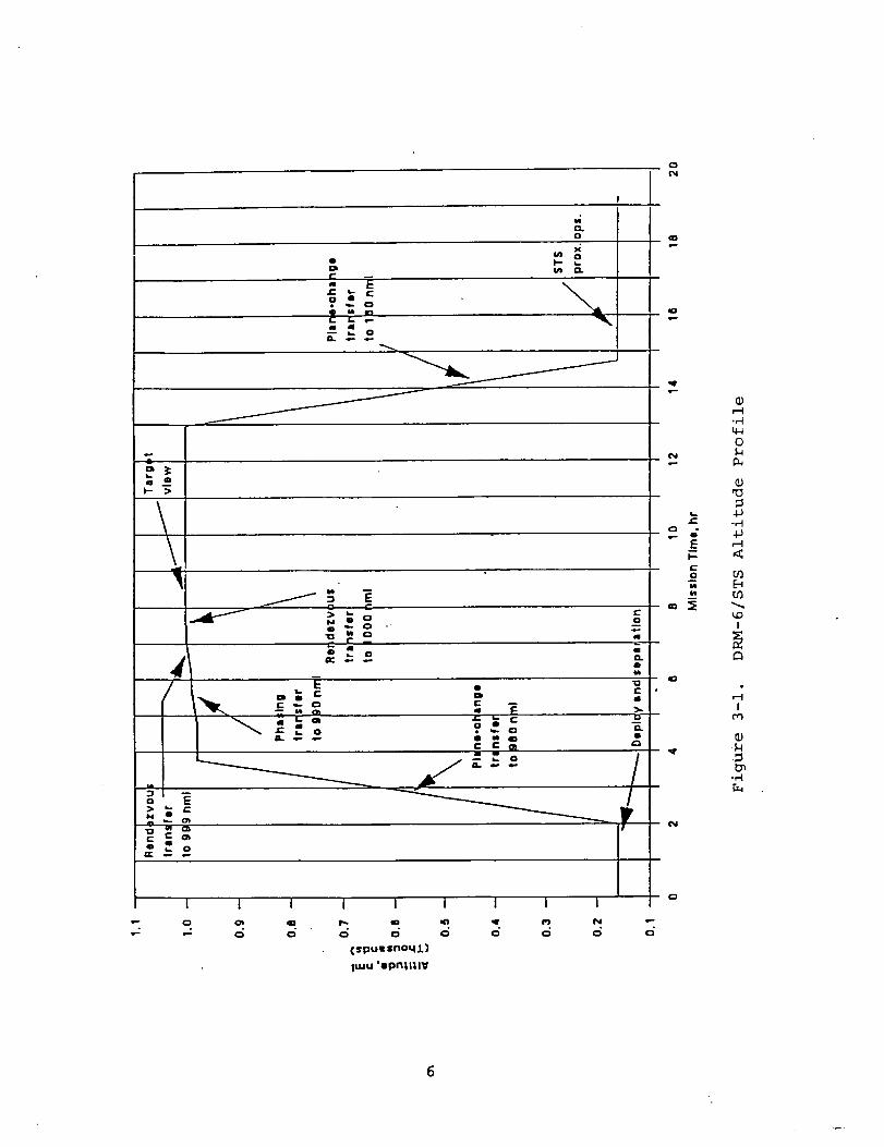
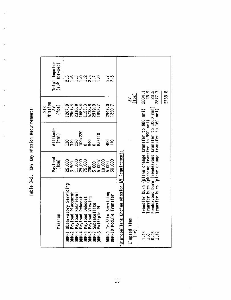
• Low earth orbit is another mission application. One
application uses the Orbit Maneuvering Vehicle (OMV)
or another similar vehicle to go from shuttle cargo
bay to Space Station or from Space Station to the
required mission. Table 3-2 shows the typical OMV
missions and their requirements. Figure 3-1 shows the
representative mission selected for the system study
since it utilizes the greatest _V requirement.
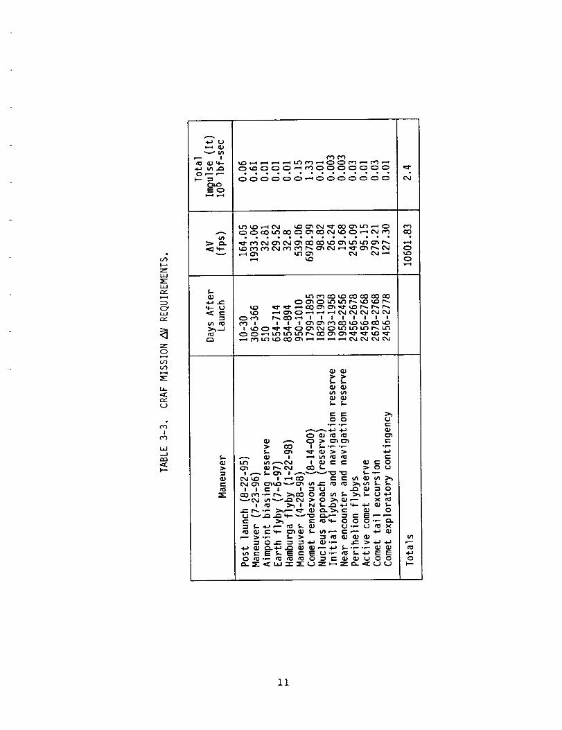
• The planetary application is another representative
mission. The Comet Rendezvous Asteroid Flyby (CRAF)
was selected as the typical planetary application.
The mission is shown in Figure 3-2 and the _V
requirements are shown in Table 3-3.
I
?'o ",_IaM la
_ " o.... j
i,- >
UI =_
-o
I i i i I i I i i
(spuwsnoq.t)
I,,,u 'opntltlV
r-
-- (:
v.-
(_
0
(11
4J-M4J
E_
I
I

%
z
U _
C0
-,-t
0
uC
<
C
U_
D
C
C0
U)
U_
r..)
¢N
I
t_-,-t
7
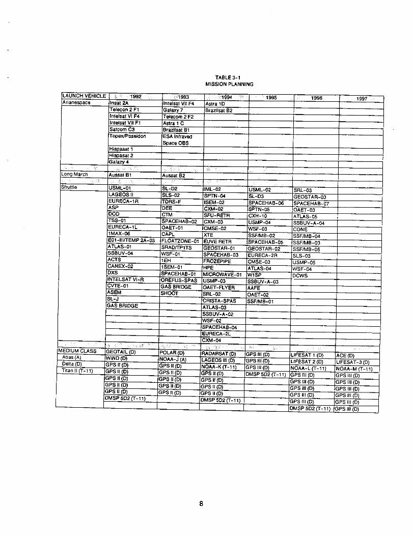
TABLE 3-1
MISSION PLANNING
LAUNCH VEHICLE , 1992 : 1993Insat 2A Intelsat VII F4Arianespace
Long March
Telecon 2 F1 Galaxy 7
Intelsat VI F4 Telecom 2 F2
Intelsat VII F1 Astra 1 C
S_tcom C3 Brazilsat B1
TopexJPoseidon
Hispasat 1
Hispasat 2
Galazy 4
ii_iO ,V:_{;I_ : :iiAuSsat B1
Shuttle USML-01
LAGEOS II
EURECA-1R
ASP
ODD
TSS-01
rEURECA-1L:1MAX-06
E01-III/TEMP 2A-03
ATLAS-01
SSBUV-04
_,c'rsCANEX-02
DXS
INTELSAT VI-R
CV"I'E-01
ASEM
SL-J
GAS BRIDGE
ESA Infraved
Space OBS
1994 ..... 1995 1996
Astra 1D
Brazilsat B2
Aussat B2
MEDIUM CLASS
:" : : : " 7 I- I
Atlas (A) WIND (D)
Delta (D) !GPS II (D)
Titan II (T-11) GPS II (D)
SL-D2 IML-02 USML-02 SRL-03
SLS-02 SPTN-04 SL-D3 GEOSTAR-03
TDRS-F ISEM-02 SPACEHAB-06 SPACEHAB-07
DEE CXM-02 SPTN-05 OAET-03
CTM
SPACEHAB-02
OAET-01
SFU-RETR
CXM-03
CMSE-02
XTECAPL
CXH-10
USMP-04
WSF-03
SSF/MB-02
SPACEHAB-05
ATLAS-05
SSBUV-A-04
CONE
SSF/MB-04
FLOATZONE-G1 EUVE RETR SSF/MB-03
SRAD/TPITS GEOSTAR-01 GEOSTAR-02 SSF/MB-05
WSF-01 SPACEHAB-03 SLS-03
I1EH
1SEM-01
SPACEHAB-01
OREFUS-SPAS
GAS BRIDGE
SHOOT
FROZEPIPE
HPE
EURECA-2R
CMSE'-03
ATLAS-04
Wl SP
SSBUV-A-03
AAFE
MICROWAVE-01
USMP-03
OAET-FLYER
SRL-02 OAET-02
CRISTA-SPAS SSF/MB-01
ATLAS-03
SSBUV-A-02
WSF-02
_SPACEHAB-04
EURECA-2L
CXM-04
GEOTAIL (D) POLAR (D) RADARSAT (D) GPS III (D)
GPS III (D)
GPS III (D)
DMSP 502 (T-11)
LAGEOS III (D)
NOAA-K _-11)
GPS II (D)
GPS II (D)
GPS II (D)
DMSP 5D2 (T-11)
NOAA-J (A)
GPSII (D)GPS I! (D)
GPS II (D)
GPS,II (D)
GPS II (D)
GPS II (D)
GPS II (D)
GPS II (D)
GPS II (D)
USMP-05
WSF-04
DCWS
LIFESAT 1 (D)
LIFESAT 2 (D)
NOAA-L ("1"-11)
GPS II1 (D)
GPS III (D)
GPSIll (D)!GPS Ill (D)
ACE (D)
LIFESAT-3 (O)
NOAA-M (T-11)
GPS III (D)
GPS III (D)
GPS III (D)
GPS III (D)
1997
DMSP 5D2 (T-11) GPS Ill (D) 'GPS III (O)
DMSP 5D2 ('1"-11_ GPS III (O}
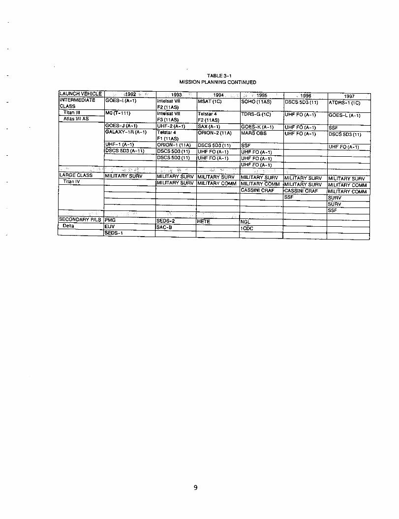
TABLE 3-1
MISSION PLANNING CONTINUED
LAUNCH VEHICLE,,!:; : _1,992,,
INTERMEDIATE GOES-I (A-l)
CLASS
Titan 111 M0 (T- 111)
Atlas 1/11AS
GOES-J (A-l)
GALAXY-1R (A-l)
UHF-1 (A-l)
DSCS 5D3 (A-11)
LARGE CLASS MILITARY SURV
Titan IV
SECONDARY P/LS PMG
Delta EUV
SEDS- 1
,:;!993 ,: : ::::,1994Intelsat VII MSAT (1C)
F2 (11AS)
Intelsat VII
F3 (11AS)
UHF-2 (A-l)
Telstar 4
F1 (11AS)
ORION-1 (11A)
DSCS 5D3 (11)
DSCS 5D3 (11)
Telstar 4
F2 (11AS)
1995 :
S0HO (11AS)
TDRS-G (1C)
SAX (A-l) GOES-K (A-l)
ORION-2 (11A) MARS OBS
DSCS 5D3 (11) SSF
UHF FO (A-l) UHF FO (A-l)
UHF FO(A-1) UHF FO (A-l)
UHF FO (A-l)
| i
: :r¸, ; , ; , ,
MILITARY SURV MILITARY SURV MILITARY'SURV"'
MILITARY SURV MILITARY COMM
: _i̧ ,..;::_,,:,: , _!i!;
SEDS-2 HETESAC-B
MILITARY COMM
CASSINICRAF
:i,, 1996DSCS 5D3(11) ....
1997
ATDRS-1 (1C)'"
UHF FO (A-l) GOES-L (A-l)
UHF FO (A-l) SSF
UHF FO (A-l) DSCS 5D3 (11)
UHF FO (A-l)
/,
MILITARY SURV
MILITARY SURV
CASSINI CRAF
SSF
'" MILITARY SURV'
MILITARY COMM
MILITARY COMM
SURV
SURV
SSF
1CDC
NGL:i ¸ .............
vi
I::
E
1-
c_
t-o
vI.r,-
0
io_
CL_
u
a
o ,,,,-M
o ...-,,,.,
°t,...,
,,.,.s,_,.._.i.J ._o_ Icz
c
o s=
>.,_,.-
eeeeeeee ee
Oieeolea e¢
oo
oooo o _ oo
o ooo _o oooooo oooooooooo ooooo
-_ --ooo-o-
c-O
vI
¢ti-l.Je.-c_
c_°I--"
r,.,,
,ca
o
v5u5
,r'-
4:=o_
¢...IJ=i
4..Jc-
O
oli
CDE
°_
_e_e
_0
o_r_L_
10
I--"Zi,i:E:i,i
CYLIJ
ZOi..-.l
C/'}i.-,=s
ii
,-y.C.b
!
i,i
I-'--
EOi.==1
¢#5
{lJ
4-- _.1
crl t0
C_
I'0
oioeellJQeeeeo
* iieooe ie •
C_OO
*_ -_
l_l_VV_
IICI I_U_-_ _ O _ _ _
I_ _IN__._ _ _ _C
_O__-_
_ _ _ _ _ _ _ _-_ _
11

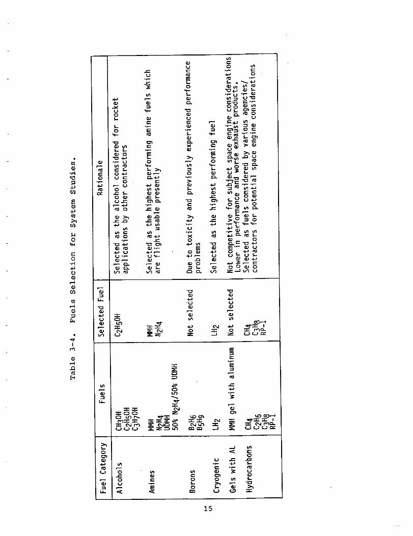
3.2 System Analyses
System analyses were conducted for each of the three missions
of 3.1. The fuels considered and selected typical for thesemissions are shown in Table 3-4.
3.2.1 Engine Performance
The engine configuration utilized for this study consisted of
100-400 ibf thrust radiation cooled engines operating at i00-
400 psia chamber pressure. This selection was based on the
use of multiple liquid bipropellant engines to avoid single
point failures. Rhenium thrust chambers were used to achieve
the high performance (4000°F wall temperatures). A high
thrust version was investigated using I000 ibf thrust
regeneratively cooled engines operating at 400 psia chamber
pressure. The engine performance used is presented in Table
3-5 and was anchored to the TRW dual mode engine which is
qualified and successfully flying.
3.2.2 System Configuration
The baseline system to be used for evaluation which is
presently flying on communication satellite applications to
GEO is shown in Figure 3-3. This configuration was based on
evaluation of the various system options and includes the
following:
• Pressurization - regulated pressure-fed system using
GH e at 7500 psia in spherical graphite/epoxyoverwrapped tank with aluminum liner.
• Propellant storage - two oxidizer and two fuel tanks
which are cylindrical with elliptical heads and
are graphite/epoxy overwrapped with aluminum
liner. MLI is used for the cryogenic tanks.
• Perigee/apogee engines - radiation cooled as discussed
in 3.2.1. The low thrust version used a total
thrust of 400 Ibf (i, 2 or 4 engines) while thehigh thrust version used a total thrust of
2000 ibf (2 engines).
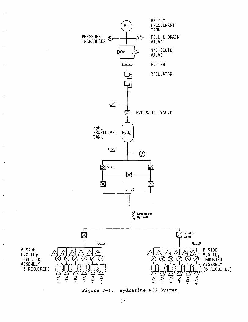
• Reaction control system - decomposed hydrazine system
per Figure 3-4. For LO2-N2H 4 system, the
hydrazine is fed from main hydrazine tanks.
The ground rules used to analyze the various applicationsand fuels are:
• Residual - 1% of total propellant was considered
unusable for all applications including OMV andCRAF.
12

td
U_L_JU
ig
W
0 =-_1 I
1.40
4-I
In
C0-,4
0
0
D_
44CI-4
_d•_ 4-14-1.,-t
m _
_0
I
t_.,--I
].3
_) HELIUMPRESSURANTTANK
I
I ._R_ FILL & DRAINPRESSURE GTRANSDUCER I VALVE
I lI_- _ N/C SQUIB
[_j VALVEI
FILTERl
REGULATOR
___= N/O SQUIB VALVE
Ii
N2H4PROPELLANT _2H4i
TANK _,.)
I
_ Line heater(typical)
A SIDE
5.0 IbfTHRUSTERASSEMBLY(6 REQUIRED)
I
< < < < < ,(
mr- mr" _,_ t'i m_ Nc'N-4- z .). z +
Figure 3-4.
I
Isolationvalve
' . B SIDE
l__ i _ i. I I ASSEMBLY
__=__]_ (6 REQUIRED)
< < < < <mr- m _,.. _
+ ! + ! N N
Hydrazine RCS System
14
'0
4Ju_
_J.P
0r3
0k_
0
tJ_J
_JO_
u]
,q,I
re)
,-4
[_
i---._J
i,
"o(1;
•4-1 -r-cJ 00J I._ ,or
,-- --r- -r- .-.e.0J o,J _" cxJ
"r"
u_ o_o,m 0
t-_-_ _ _ -r- _ o\o
""J_' O,,J P._, _
QJ c_;
-,,JGJ
cO,--._•,N' _ 4-_ _q-"r" io -.r- o -r- t"__-
0
0
,-- 0
•"r- -t- Cx.IL'_I u_ "t-
E
E
o_,,-
i_,,,o cO,.--'+
•m- ,,_--r- -T- i
e-
t_
ot.-o
0
•_ -4-+ S..
C:_ 00 _ S--
15

0
o
G
!
E
E _n v
•,-- v
U 8
q.}I.- 0
X _0-v--
-' E
qJZLv
eC_
_00_0_
vv vv
e=om
_0
vvvv
eee.
VVV_
eeeo
_00_0
VVV_
ee°e
_ 0
_ _vv v
_0 __ 0
ee,e_0
v vvv
_o,
vvvv
M_O
vv_v
,°°,
_vvv vv_v v
v_v_ _v_
_v_v v_
eli. ee.
0000 _
__ _
Z
._v
t-- Z
8
C
%0
0000
0000
_0_
v_vv
00000000_0
0..J
0000
0000
_0_
00000000_0
I
0
0000
0000
_0_
vvvv
00000000_0
C_D
!
0-m
0000
0000
_0_
vvvv
00000000_0
0
!¢q0
0000 0
0000 0
_0_
0000 00000 0_0 _
I
0.-1
),..-v
CM
Z!
_J
0000 000
0000 000
_0_ _0_
0000 0000000 000_0 _
Z
_ ,0 0
16
• Boil-off - 0.4% of the cryogenic propellant was
considered boil-off except for high thrustcondition which used 0.25%. These losses were
used for all applications including OMV and CRAF.
LH 2 losses were established at 6.1% (based on
AFRPL-TR-86-045).
• Startup/Shutdown - 0.5% of total propellant used for
all applications. For LH2, 2% was used.
• Thermodynamic vent system cooling - 2% total of LH 2.
3.2.3 Results of System Analyses
System analyses were conducted to evaluate their weights to
orbit fSr the three types of missions (GEO, OMV, CRAF)defined in 3.1.
3.2.3.1 Perigee/Apogee Applications
The investigation of mission applications indicates perigee/
apogee applications have the greatest usage potential in the
foreseeable future. Therefore, the system analyses for these
applications are most important and the results have the
greatest impact. The analyses used the Delta 7925 (6000 ibm
into LEO) and Atlas IIA (14,750 ibm into LEO) as typical
launch vehicles. The results of the analyses are presented
in Table 3-6 which indicates LO2-N2H 4 is the best propellantcombination to achieve the greatest weight into GEO. These
weights consider the major subsystems except for the RCS
system and system components (regulators, valves, lines,
heaters).
The hydrogen tank volumes (~ 450% of amine tank volume) are
so great that LH 2 could only be integrated into the vehicle
using toroidal tanks necessitating aluminum toroidal tanks
due to unavailable overwrapping toroidal tank technology.
This results in non-competitive weights into GEO.
The impact of the RCS subsystem was investigated. Figure 3-4
shows the system used to assess RCS impact based on a
_V = 1465 ft/sec for RCS and stationkeeping. Figure 3-5
shows the RCS weight impact on payload into GEO.
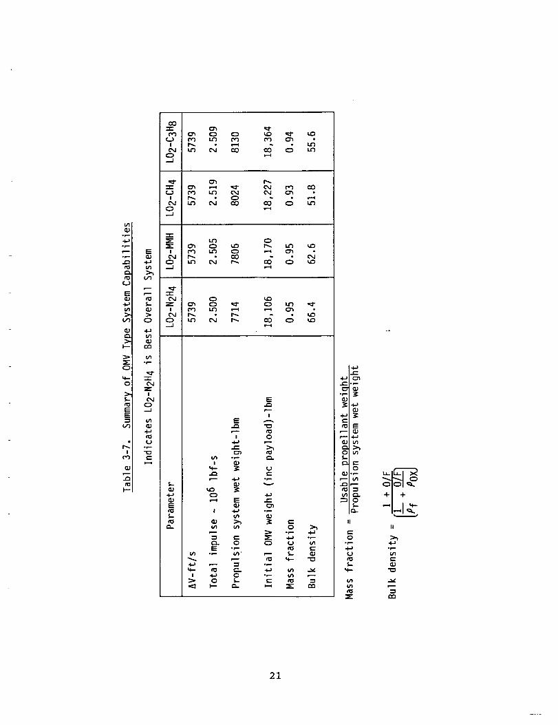
3.2.3.2 OMV Type Applications
System analyses were conducted to determine the best
propellant combination for a typical low earth orbit
application and the OMV viewing mission (DRM-6) was selected.
The four best fuels (amines and hydrocarbons) were selected
for the analyses including N2H4, MMH, CH 4 and C3H 8. Thepropulsion system was similar to Figure 3-3 except four
17

i_ l'r"
_ <_
°_
!"- ._"1"CIII
,,_.,I
',x\_ r,,,,\",O\\\\
k\\ x,,,\_ \\",d
B_"x\\'_
-'r-o
-'r
o,._1
I
' .,_,1
_.1
E:I,\\\_
k"x",t,,\\N",,,',,,_
l,k.\\x,k\\\,',,,,,\_
_\\"_,,xx,.\\\_\\\_\\\",_
\',,x_',t,,,.\\\_,.,_K{_
K,
I t 1
_A
"I-C_
Z
Ic_O_A
Z
O
Z
m
O
F-Z
_JW13_O
13_
_o_
O
_ o_
(_;pu D_;nou._L)
18

JI
o')
E_
0
0
c--r-
e--
°r-Q;
O,J"r"_J
IO,J
O
"T-O
Ln-r-C_J
IC_
O.-J
IOd
Q
C:O-r-
!
O..d
"r"
!O,J
0...J
IC_
0.--I
• ,-- e- _d.l_q;o,-- _,---
-r"
Z C',J
C_J0_J
"t-
_'.--J r_I _ C_
v
f.n .._ 0
-_ 8I--. 1.1_
v
C_0
C_ _ CO
t--. CO
0 C_0 O C_
O,J _ C_
0 O 0C_ C_ 0
_C_ O
O,J
CO CO 'q" u'_
¢0 _ ¢n0 r-,.,
L_
O,J
_0 O,J C'_ 0
0_ C_J O,J
O,J t'_ Od
CO ,-_ CO COL_ _0 L_ L_
0
0 Q 0
_ 0 0
I9
engines of i00 Ibf thrust (operating at i00 psia chamber
pressure) were utilized for this application. Two engines
operate simultaneously for each maneuver and the other two
engines provide redundancy. The results of the system
analyses are presented in Table 3-7 and indicate LO2-N2H 4 is
the system of choice as it provides the lightest initial-
vehicle/system weight and highest bulk density and massfraction over the other candidates.
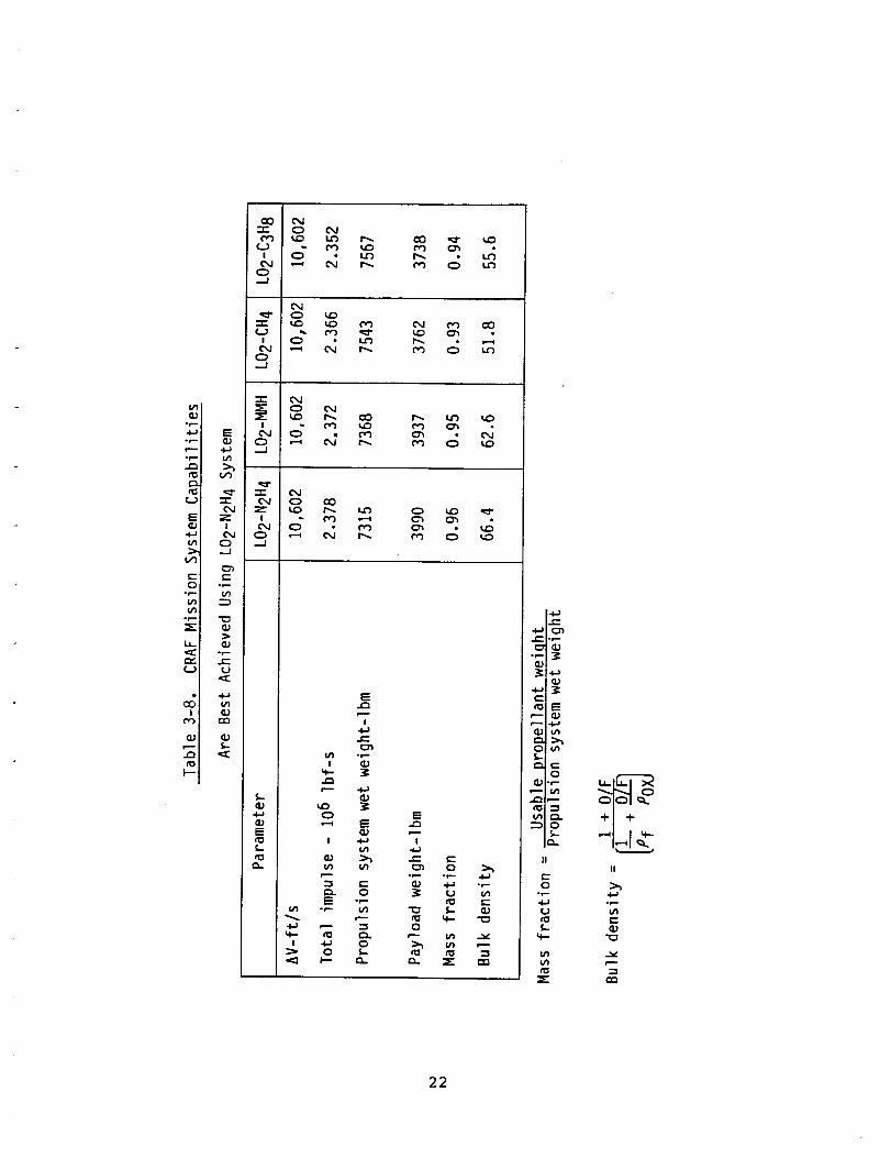
3.2.3.3 CRAF Application
System analyses were conducted to determine the best
propellant combination for a typical planetary mission and
the CRAF mission was selected - current plans show the use of
a typical bipropellant system similar to our system studies.
The four best fuels were evaluated using the same regulated
pressure-fed configuration of Figure 3-3 but using only one
I00 ibf thrust radiation cooled engine operating at i00 psia
chamber pressure. The initial spacecraft weight is 11,305
ibm. The results of the system analyses are presented in
Table 3-8 and indicate LO2-N2H 4 is the best system as it
provides the maximum payload weight with the lightest system
and maximum bulk density and mass fraction over the othercandidates.
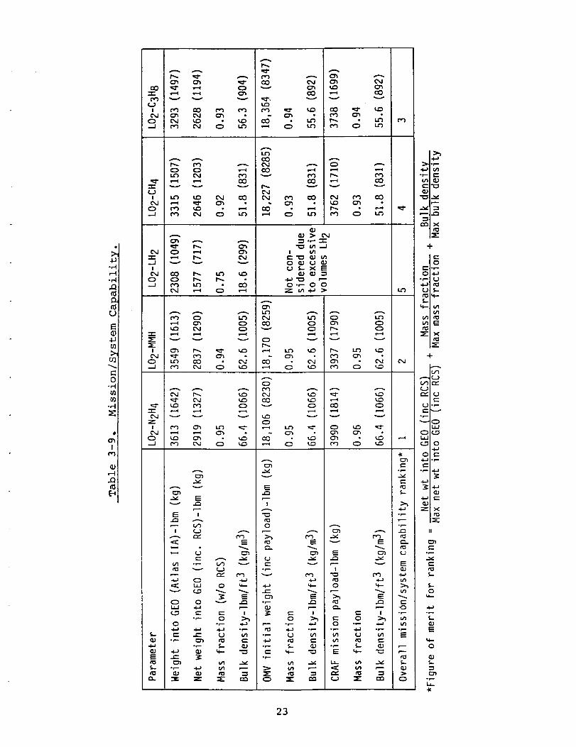
3.2.3.4 Summary/Conclusion
Based on the system analyses, the overall mission/system
capability is summarized in Table 3-9. Using the Figure of
merit defined and presented in Table 3-9, LO2-N2H 4 is thebest propellant combination.
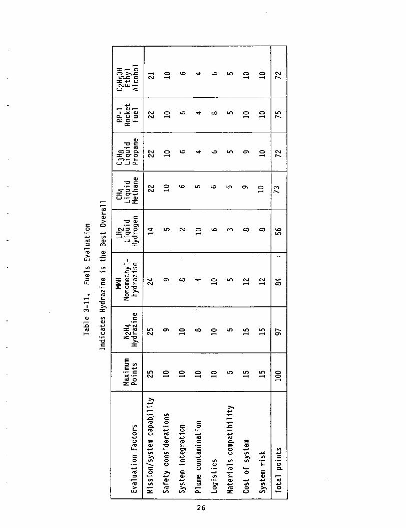
3.3 Fuels Evaluation
The seven selected fuels were evaluated to select the best
engine and system to achieve the mission applications. Eightevaluation factors were considered in the evaluation.
• Mission/System Capability
The evaluation factor considered weight and volume
considerations of engine and system. The figure of
merit and evaluation of Table 3-9 were the basis ofevaluation of this factor.
• Safety Considerations
The safety considerations included three factors--
flammability, explosive potential and system safetywere the major considerations.
2O
Q;or..-
or-
ol.-
4-
O
E
_JI
¢O
.Q
I--
CO
_ OJ CO CO _ LnO.--J
C'_ I.n O,J CO CO _ L_
-r-
C',J r,-. CO oJ
...J
-r-
zICM
O._J
E
4-i
E
IE
I 0
_ o_
°_
°_
I_ °r-
4._ O ",--
U _
_.) °p-
--'_ 0
II
e-0
op-
I._
II
21
o_
Ol,-.
i--
°v-
t_
°r-,-
°r--
i--r,_
0
' 0
0-J
-r" 1.0
, o"0
"lVl
_" _ r'_I -
.-J
ZI
0 ,,--'..J
4.J
<._
I
cxJ r-,, i-_ o
_.o _ _ ¢._¢'_ _ _ o_ •
_ •c_ o _o
cO
r-,,
o i.o
E
e-
o_
l ¢l;
¢]; ,--1 4._ !
0
o f,.-
f,..
(u u_
_1 c_.
II
oo_
f,..
u_
t_
Ii
t.-0.)
22
-,'-4
-,-I
u
0U)
r_
Ic_
A
O'_ O'1
i ce) CO
O C_l I.o
f.e,)o-i
c_
A
O O
"I" _ v
A
ACO
O
_g d
mm
cM
d
I
-.J c,") I,_ • COC_I .--I O .--i
:E:
Ev
E I
I _
(._ _'- £'- I• ,- O
O o,-'-
u_
o_.- £_
=
c_
O'1
C'xJCOv
O
Ot,.y-.)C'xJCOv
O
v
E
!
O
t_
r_
Olm0.)
v-.,...
o_.-
or..-
"s-O
£x.IO'1COv
e...-i
c") CO
U _ XE
0-,- 0 0
0
0
0
u")
X
A
v v
CO __ •
v
_ •• _
0 I,,,£')
O
O r_
c_O'1
_ m
mN
m
"_,
0
0
00
v
0
v
e.-
?_
A -_'-
0 _--" >'_
(- O _ u')
*r-.. 4,.) • r-... -_u')
-,- _.- 0.)
"4"
-r-] _.)
-I_ tOr,..) 5,-
-7×
II
c-
O
"V_
0
23
• System Integration
System integration considered two primary
considerations--RCS and fuel integration. The RCS
must be integrated to achieve minimum weight and
complexity while achieving high reliability with the
necessary control. In all cases, hydrazine RCS was
used as the system due to its high reliability and
demonstrated flight data base. Fuel integration
considered insulation of cryogenic tanks and lines
and design of regulators and valves.
• Plume Contamination
The exhaust products at the nozzle exit were
evaluated based on the engine operating conditions.
The major toxic constituent was determined to be CO
although the amine fuels had traces of NO. The
exhaust products are summarized in Table 3-10.
• Logistics
The logistics considerations were based on the use
of the fuel for flight at the launch facilities.
This factor considered shipping, storage,
availability of fuel, ground support at the launch
facilities and validated operating procedures at thelaunch facilities.
• Materials Compatibility
This factor considered seals and materials that are
compatible with the fuels.
• Cost of System
The cost assessment included development, recurring
and life cycle cost of system/engine.
• System Risk
The risk assessment included development and
recurring cost and schedule risk.
The evaluation of the eight factors is presented in Table
3-11. The results indicated that LO2-N_H 4 is the best
propellant combination of the eight evaluated. Therefore,
TRW recommends the use of LO2-N2H 4 in the development of the
Space Storable Test Bed Rocket Engine.
24

-I-)C
or--
I,'1t"0
(J
U
0L
C_-
v1
..E:X
I,I
I('_
rt_
op- I=
fO0
(J4.a
I-"c"0
(J
CMZ
p.-0E
I
tMA 0
v
_" CM
"_ LJ
op-
0 0{J U
0f- CMX
U
*r--r--
or-- "P
{/1
e"
°l---X°r--
C'--Q
(,J
{_. of..
P- ¢=_J ol.--
L 0
o\ o o\o o\ ot._ _
c:; c;I I I¢M tM "r"
O I:_ Q
o\O ..... .. o\o o\ oo\ o o\ o o\ o _
• ¢_ ¢M ¢'_ • •
•-4 ¢-_
e
" _ " " _ " d
d _: _4 _ g M _d
::=O
tM _" "_ I "P = =-I- = ¢_ _.. CM _" tM--J U U P_" U _" Z
i I I I I I IC%1 _ C%J C_ C%1 C%,1 C%J
0
t_
0
Or_
U
0
.g-r,,-
e--
0
e-
e-
't¢
A
0
OI
!
U
-k
25
c_
O•_ 4-)-I-) u')
UJ ._
"_ (1)
°r_N
¢O :3::
r_ ._
°_...
C
•-r- ,-. O
O--r- 4..) U
4-)_,--I CJ F---
l _.. G.)O_ Cj --_n.- 0 i.i_
o_¢_ "_ _.
-.r- _- o(.,_. ,- _._
q.)
,,_- .-._ _.--r- {_.- .+.._
...j _"
C_J_ O"-r" _r- __.._J .,- -_
._ >_"-r-
I,'--- (1)
o_-.4-) N
-.r- (1_ _.0
_'O'_
O _-
(1)
OJ_.-
>_-'1-
E"_ u')E'_
X oP-
t_S-O
u
(...O
o_..
n: O e.- ._.-
e: 4-_ O -,- -,'-
G) "_ _ .,- t=:
tn O _ _- ul ulU "_-- 0 U r--
t::: U -r-
-,-- _ (1) GJ vl _-
"," _ >'_ ,'-" O
E
•_ u_
fj_ or.- ot,,-_.- O
o E
u_ _n 4-)O >., O
r._ u') t.--
26
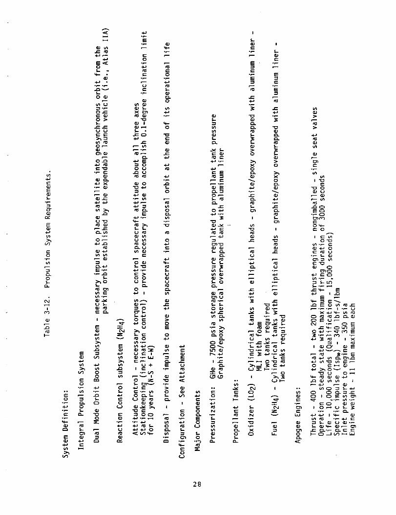
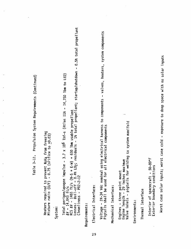
3.4 System Requirements
A preliminary set of system and engine requirements have been
established based on the system studies and TRW experience
with systems and engines. The system analyses indicated that
the payload to orbit optimized at 200 Ibf thrust and 200 psia
chamber pressure. Therefore, this was the recommended design
point pending further testing. The preliminary system
requirements are shown in Table 3-12. The engine preliminary
requirements are shown in Table 3-13. These requirements
will be updated as test results necessitating change becomeavailable.
3.5 Applications Evaluation Conclusions
The maximum mission potential usage for the Space Storable
engine is placement of satellites into GEO for NASA, military
and commercial applications for communication, surveillance,
tracking, earth observation and meteorology.
To achieve this mission potential, an evaluation of the
various candidate fuels indicated that LO2-N2H 4 is the bestpropellant combination and provides the maxlmum mission/
system capability. The preliminary system and engine
requirements provided the basis for the preliminary design
and indicated the nominal engine design as follows:
Propellants
Thrust (F_)
Chamber Pressure (Pc)Specific Impulse (Isp_)
LO2-N2H 4200 ibf
200 psia
340 ibf-sec/ibm
27
bO
(--qJEk.
CT(D
r_
E(3.)
t/)>_
o,3
Oor-u')
"3C2.O5.-
Q_
ICO
(1.)
¢Ot--
_J
e'-O
0p--oo r,_e-" e--O "_
or-- t_-_ Oon- f,.
_" £3-or--',4--
(1) tOr'_ f,..
E
Ct_O *.-*
t_
e-_J
e-
tO4-.;4-)
_D
I
O•t,.--
tO%.-
q--c-O
¢.J
ee
e-. roo N
5-
5.- _;O 5-•,--j _.
e.
v
4=) 5,-
No_--
._--
I
OJ m
._,-.
._,_
e- _.-
o_.
¢0(I; 5.-
o_- _
I'_ oe-
I %--
rO
e--_J
e- _-.
"_ 4-)
_ Qj e-.,-
or- _. e-
¢.J _-- _-- .,--
!
C_
e.
G.)e-
op-
e'-L._
0J_JU:nO
28
U
c_Q;
e-
Q_
e- _.}°_
L_JQ;
Q;
O
O
Q;
Q;
Q;
Q;
I
u_
e-Q;
O
EOU
O4.J
Q; _--_-- Q;
Oe- C_.
EO{..}
_J
"Z %
e- O
t.1 -'_
_1 e-" _
!
O0,- e-
O
O
e-
E,--°r- i_x 3=
._ _ _.O
•"_ u_ u,.-O Q;
U,---
_._
OCn _C_. 0,J o,-- QJ
(_ I 4--.
e- c--u'_ .,- Q.)Q; Q; Ee-e-Q; t--
¢-
Ou_
O
e--
°_
Q;(..)
o_
_PQ;
O
u'}O
XQ;
!
O(0
QP
It_ ._
O I.-CO O
,r--
op.. -._
4"- Q m
f,. _.
"V.."E _,-- l,-
_ e- X
e--
29

CGJE
_J
E_J
:h
O
r'_O
O..
Io3
(IJ
.£3to
N N N
O O Oo_ o_ •
_@OIO
IIIII
NNNNN
eeb'--
e--O
EO
e-
!U
oF..-E
e-
N NN
_ 4_ ::3:: ..I_ _
I.O i::0 i_3_O
O.1. O I O
! I I I I
N N N N N
I ¢_1 ¢",J¢_10 n
CO
Oor--
or....
op,..
Ef,-!
ool,n
oeD
¢,..9
e-
4-:
_J
_- 0_0 _,.
E
_J
| op..
(u _J
o_...,..-4-.
O
i,n -,_
_°_
r_ .t..I_ e--
O
4- e"
ro _.-
_ E ""-
_- O
"" ._
30

Table 3-13. Engine Requirements
Thrust (F®)-Ibf
Mixture ratio (O/F)
Specific impulse (Isp®)-Ibf-s/Ibm
Inlet pressure - psia
Fuel inlet temperature - °F
Oxidizer inlet temperature - °F
System mixture ratio
Life - sec
Maximum continuous firing - sec
Operation
Operating voltage - Vdc
Engine length - inches
Engine diameter - inches
Heaters
Valve seat leakage (scc/hr GHe)
Random vibration
Qual - 14.1 g-rms20 Hz - 0.026 g2/Hz
20-50 Hz - +6 dB/oct
50-800 Hz - 0.16 g2/Hz
800-2000 Hz - -6 dB/oct
2000 Hz - 0.026 g2/Hz
Oxidizer-fuel inlet pressurevariation
Alignment
Engine weight - Ibm
Contamination control
200 +10 (890 + 45 N)
0.75 +0.03m
2340 nominal (Z 3334 N-sec/kg)
+0 +0 N/cm 2)350_10 (241 -14
70 ±10 (excluding heat soakback) (21 _ 6°C)
-285 (excluding heat soakback) (- 176°C)
0.75 +0.08 (includes pressure andtemperature variations)
10,000 (qual - 15,000)
3000
Steady state (performance at >30 s)
24-34
29 maximum (74 cm)
12 maximum (30.5 cm)
Required to prevent fuel from
freezing
5 per valve seat
A/T - 10.0 g-rms20 Hz - 0.01 g2/Hz
20-160 Hz - +3 dB/oct
160-250 Hz - 0.08 g2/Hz250-2000 Hz - -3 dB/oct
2000 Hz - 0.01 g2/Hz
Fuel = +5 psia of oxidizer pressure
+0.5 degree
11 maximum (5 kg)
PR2-2-12Valve must have 25 micron inlet
filters
31
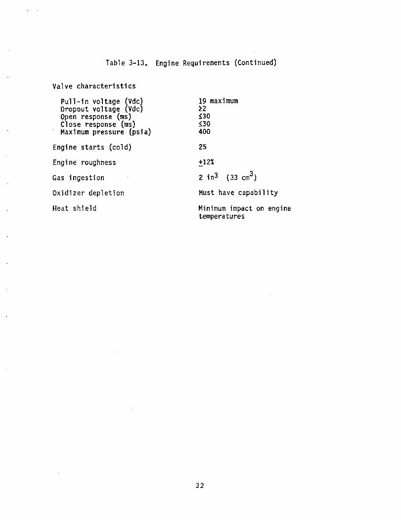
Table 3-13. Engine Requirements (Continued)
Valve characteristics
Pull-in voltage (Vdc)Dropout voltage (Vdc)Open response (ms)Close response (ms)Maximumpressure (psia)
Engine starts (cold)
Engine roughness
Gas ingestion
Oxidizer depletion
Heat shield
19 maximum22_30(30400
25
+12%
2 in3 (33 cm3)
Must have capability
Minimumimpact on enginetemperatures
32
4.0 ANALYSES
The two major categories of analyses emphasized during the
Basic program were performance and thermal. The performance
analysis objectives were to establish a model to predict
sensitivity to design variables and assess ability to meet
performance goals. The thermal analyses objectives were to
establish a model to assess thermal operating characteristics
of the injector and thrust chamber.
4.1 Performance Analyses
4.1.1 Analysis of Injector
A model of the coaxial pintle injector was developed by
Dr. Richard Priem to calculate the performance based on
combustion characteristics using LO2-N_H 4. The prime
consideration was the model should preaict sensitivity of
various combustion parameters to design variables. The model
for the fuel centered injector incorporates the followingelements:
• Injection velocity - treat fluids as columns that
intersect each other. First spray is caused by slots
of fuel impinging with oxidizer. Second spray is
caused by fuel gap flow between slots impinging onoxidizer.
• Jet size and drop size - jet size of each stream is
calculated on the basis of a round jet having the same
area as the impinging streams. Drop size is
calculated using impinging jet correlation curve ofTR 67.
• Vaporization
- Prior to impingement of first spray
Assume a gas velocity of flow out of the dome
through the spray.
Using assumed velocity calculate momentum balance
to determine radial gas velocity of this flow that
would balance a decrease in liquid velocity of the
first spray to the point where the radial gas
velocity equals the resultant spray velocity.
Then calculate drag and deceleration of the sprayalong with the amount vaporized of the fuel and
oxidizer as a function of radial position.
- Vaporization of second spray - determine amount
vaporized before spray impinges on wall
33
- Vaporization in chamber
Assumes spray bounces off chamber wall withaverage angleBreak spray into five sections having varying massand bounce angleCalculate the amount vaporized in ten annularsections of the chamberWith the angle, calculate the length prior tomovement out of the annular sectionUse this length to determine effective lengthMass average all the different parts of the sprayand sum each for the various annuli
• Mixing in the chamber - simulate mixing bytransferring 10% of each flow from adjacent annuliinto each other. This is done on a flux differencebasis and area of smaller annuli.
• Final performance - based on O/F in each annuli andmass flow, sum the mass averaged C* to obtain engine
C* and resultant combustion efficiency.
The results of this model were used to predict the trends for
combustion efficiencies (C*) of the various elements. Themodel was established based on the results obtained on the
first element tested (-3) with LO2-N2H 4. These results wereused to anchor the model. The model was then used on
subsequent elements to predict the performance. Table 4-1
shows the results of the analyses and test results.
Increasing the number of slots is the most effective way of
increasing combustion efficiency (C*).
4.1.2 Nozzle Performance
A two dimensional kinetic analysis was conducted to assess
the thrust coefficient and potential vacuum specific impulse
achievable for the LO2-N2H 4 engine. The analysis was basedon a two zone model operating at mixture ratios (O/F) of
0.875 in the core and 0.5 at the wall to produce an overall
engine mixture ratio (O/F) of 0.8. The overall engine
characteristics are as summarized follows:
Thrust (F_)
Chamber Pressure (Pc)
Nozzle Expansion (E)
Mixture Ratio (O/F)
200 ibf
200 psia204
0.8
The results indicated a vacuum thrust coefficient (Cf_)including boundary layer losses of 1.89. Based on 94.o_
combustion efficiency, the vacuum specific impulse (Isp_)
would be 340 seconds. The effect of combustion efficiency on
specific impulse for the two zone TDK analysis is shown in
Figure 4-1.
34
?_ rIHI::
_tt
't t_'tttt"
, _!'r !T! t
!
____LBF- SEC / LBM
o_ _ 3]0
_o_
Figure 4-1.
Effect of Combustion Efficiency
on
Specific Impulse.
!I! !i!!Ii!_i! It!i_l_
l!]I_,_!i_i_ -_.... ]:_;
•, , ...::. _::!
i ..iiiilliiill_÷T _ :'T ", ;
iiiii!ii:,_,_,i_ iii_li!!...... :*.1! tt !rtt
iiiiiii _ii_!ii!!i._iii
_Iiii_] ]]]]
.., :::T ::t: _7 .....
....i]_i,,, it,;
_:_:_t!!.:,iilill !:_ili]ii....
i!ii iiiiiiiiiii
...... _;:+,,,.:i!t
ii._i![!q:f_ii!!II f " : : : ]
i!i!I ilil _il_i_+!: _t'!
,_f_iil!i]ilti_
iiii' !IiI_ ii!i.... H_t T_!
iii_ ,_t:.:iii!bt t q-!:
:_i] ....i]]]?_t I:i
i!ii i!]l iii Jill._Iiii!ili! i_!!
]{!]::_
i_i]i :.
";:: !_i i''::H_i F_:_ _ ....
iiii _iii]_i iiil
35
4_k4
ii i_ii
., ii_
._ I tt
:_ iiti
i! :;i:
:[ :!i;
_: _T. -r'
11 :::[
;_ _'_,
]: .:!!
2 _
ii ili_
ii !!fi!_: !!!iii ....I; ....
!i _!!f
L :_
Ti i!::tl :!i:
!t!,itlt
L
,* :ii t?I :I:
_itlij
ii ii!_
:_ ::':
_:_ :iiiT: ::i:
i_ it!]
il ;;;;
i; i!l_
li iLl,
ii....IHI_t_t
:!!;1t _
Ii i!l!
: _+'H
l :
!ir',::
!112! l
:; ;Ill
' ]2_.;HI
i!i_il51?_?T,JJ ::!!
ii :,ii_::!1
.... r"
!I :_ll
;: '.H:
1i ....,_ :11!
_' [iii
ii _!,;
r: :_ii
H ::_:
I[ :;i:
I_il!iiil_!!
!i li!i
!i....
I!':iiiRI
)i !!)i
-i fi-'_,'
ii ili:_

A
0
N
E
g =._,
_ r.- m
_ _ , , ,_< _ _. , _ ,
R __ o_ "_
E
Z
Z0
E_W_
_JM.Z0
I I i !i I
36

4.2 Thermal Analyses
Thermal analyses of the injector and thrust chamber which are
shown in Figures 5-1 and 5-2 were conducted to assess areas
requiring modifications to the initial design. Thermal
models were developed and anchored to test data prior to
assessing design capabilities.
4.2.1 Injector Thermal Analyses
A SINDA model of the injector dome/neck region was developed
to assess combustion gas heating loads from test data.
Figure 4-2 shows the locations of the injector thermocouples
utilized in test and Figure 4-3 shows a sketch of the model
with the thermocouple locations indicated.
The general approach used is presented as follows;
• Film coefficients for the liquid oxygen in the annulus
and cone passages were calculated for the forced
convection, nucleate boiling, transitional, and film
boiling regions using published empirical relations
(e.g., Sieder & Tate, Rohsenow, Gambill, and
Rocketdyne cryogenic data).
• A heating load was applied from the combustion gases
such that the resulting temperatures agreed withmeasured values.
Results for three cases - low, moderate, and high
performance - are presented in the following paragraphs.
Higher performance was accompanied by higher heating loads asexpected.
• Low Performance. The correlation between measured and
predicted dome temperatures for test number, HA2A-4000
(80% C*) is shown in Figure 4-4. The calculated
curves were applied to the noted mode numbers of the
SINDA model of Figure 4-3. Injector neck temperatures
are shown in Figure 4-5. The imposed gas temperature
for all zones are shown in Figure 4-6. The higherinitial gas temperature (1650UF) resulted due to the
N204-N2H 4 ignition; it then decreased to 450°F at 6.5
seconds when chamber pressure stabilized. The local
film coefficients required for the outer zone (Zone 1
in Figure 4-3) was significantly higher than for the
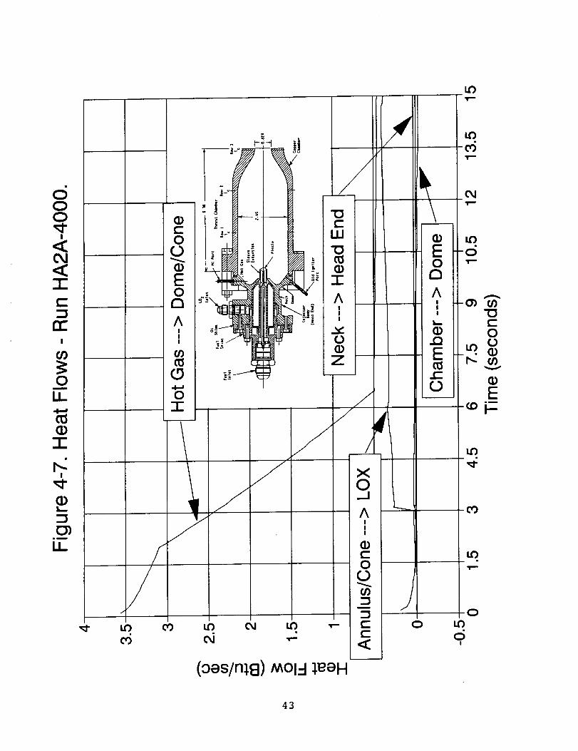
other zones. However, Figure 4-7 which shows the
transient heat flows, indicated that the LO 2 heatabsorption requirement at steady-state was only 0.5Btu/sec.
• Moderate Performance. The correlation of dome and
neck temperatures for test number HA4-3999 (87% C*) is
shown in Figures 4-8 and 4-9, respectively. The
37

! !
i I
i IC
IIEl
m
m
r-"
I
I
00_-4
-TI-ll
c-O
in
00_S
O.
EM..
c-
r-iB
0
00CD
mm,,_
c-m
e-lmCD_c-W
_O
c_!
CD
_D_in
U-
38

o
E0121
c-,m
¢-U.I
I--
!
L_
LL
[
t,09
(D_.o
o
Lr_
t-O
N
39

l.e)
(9) eJnleJedwe.I.
4O
0 0 0 0 0 0 0lO 0 LO 0 L,O 0' _'- _- Od Od tO
# # I I I
(-_) eJnlgJedLue/
4I
,,6
E8
(II ,,,
m40o_o_
,,<,
n,-I
B_
IJ_
U)
8V
0 0 0 00 0 0 00 I..0 O 1.0
(-I) eJn3,eJedwe.L
0 00If)
I
42
==
oii
G)
I
a)
mD
ii f
/
/
//
ur)
8
1
i
I
\Ii
//
#'1
J X0
I
I
(oes/n; ]) MOl-! ;eeH
dtr
J
2
6
O
uD.i,==
uO03
uO
-oj
o
_oi=
CO
kO
O
OI
43
..oF-(1)'1..f_
(_---
(b ""
(I)
Iw..,
em
U_
0 0 0 0 0 00 0 0 0 0 0(.0 Lf) '_" CO C_
0
(9) eJn_,eJedwel
0 0 00 0 0•,-- O_ CO
I ! !
0
o
.i
I--
44

LKLK
:i gg"_ _ _ LE LF."0 "0ooa_
-oI-- •
0 0 0 0 0 0 0 0 0 0 00 I._ 0 I..0 I..0 0 _0 0 I._ 0
' 0,1 _1 0"_I I I I I
(4) eJn_.eJedLue/
t-o
V
Emi
I--
4S
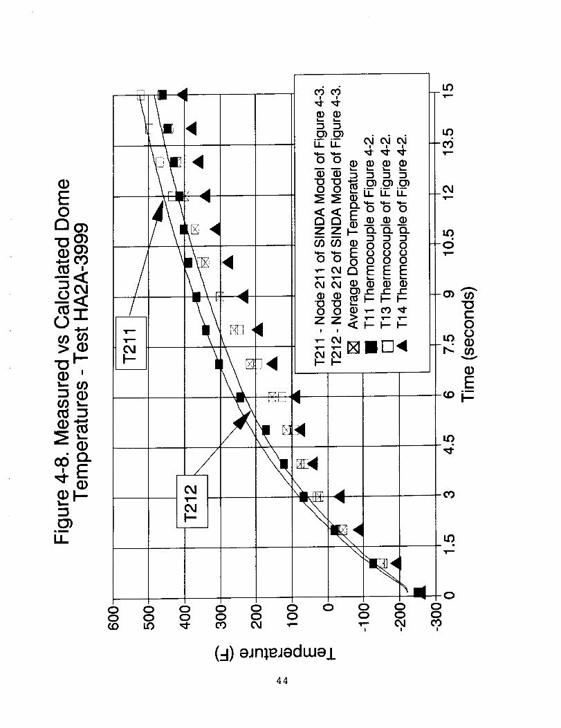
initial effective gas temperature was the same as of
test -4000 (1650°F) but the steady-state value
decreased to only 1300°F (Figure 4-10). Local film
coefficients on the gas side were the same as for test
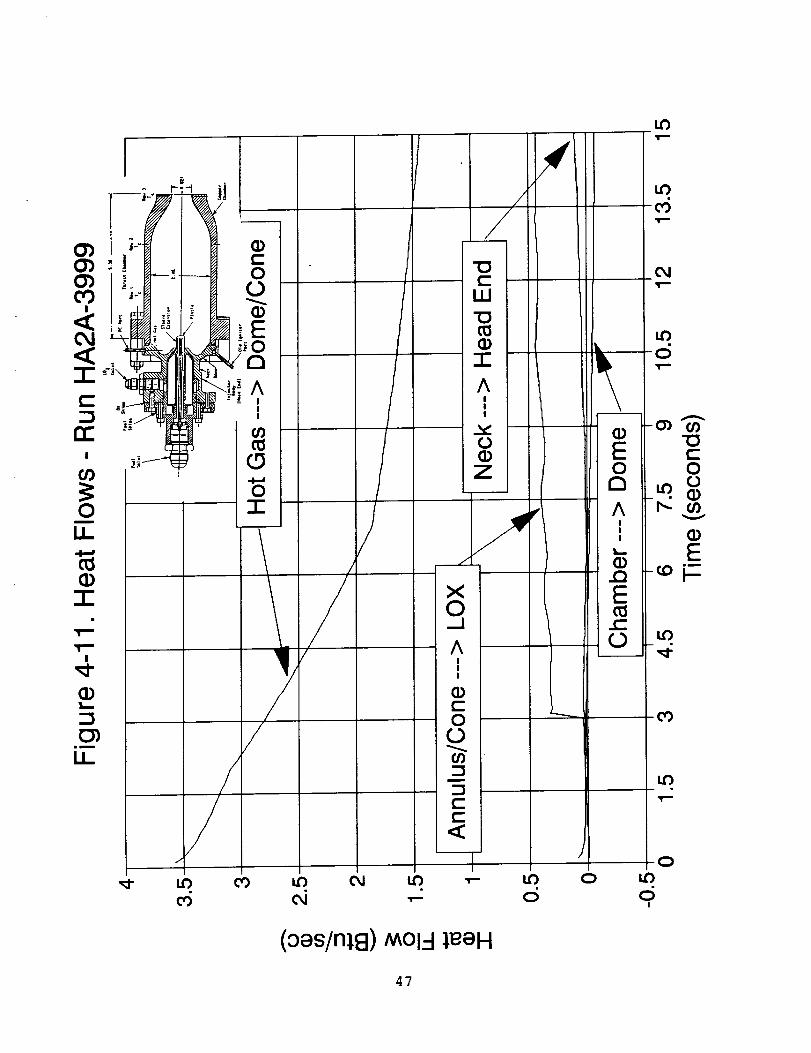
-4000. Resulting heat flows are shown in Figure 4-11.
For a 400°F dome (~ I0 secs. into the run, Figure 4-
8), the LO 2 would have to remove 1.7 Btu/sec in the
present injector design. The LO 2 was able to absorb
only - 0.5 Btu/sec due in part to film boiling over a
considerable cooling area.
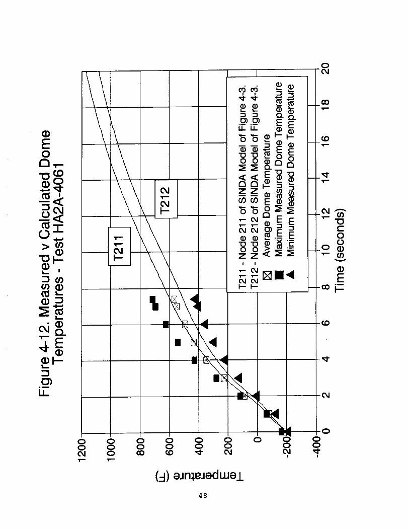
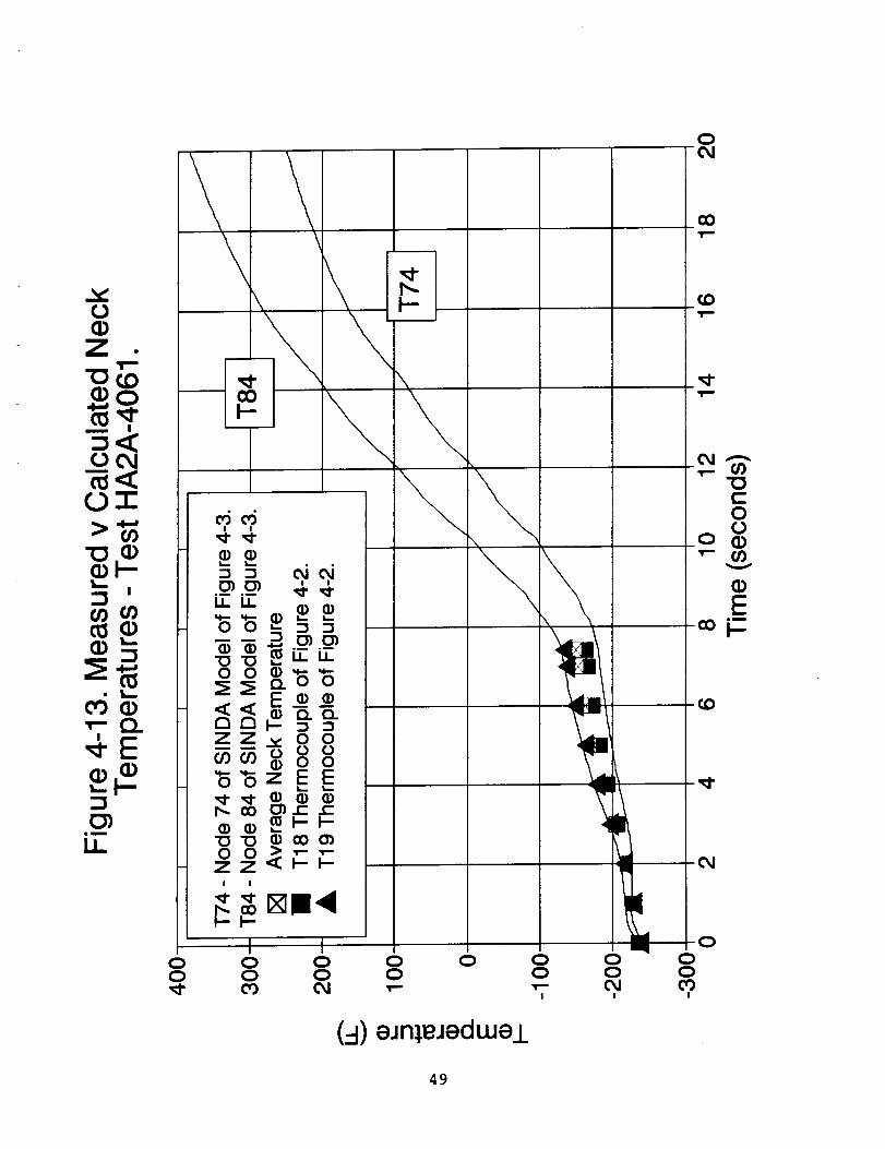
• _ Performance. Test number, HA2A-4061, with a
different injector element and at a higher pressure
than -4000 and -3999, had high performance (95.1% C*).
Measured vs. calculated dome and neck temperatures for
this case are shown in Figure 4-12 and 4-13
respectively. The imposed gas temperature is shown in
Figure 4-14. Reflecting an improved ignition design,
the initial temperature was 1300°F for -4000 and
-3999). Steady-state gas temperature, however,doubled to 2600°F. Gas-side film coefficients for
zones 1 and 2 (see Figure 4-3) were an order of
magnitude higher then over the rest of the area, but
approximately the same as those used for zone i, tests
-4000 and -3999. Corresponding heat flows are shown
in Figure 4-15. For a dome temperature of 400°F
(about 4 secs. into test), the LO 2 would have to
absorb 4 Btu/sec to stabilize the temperatures. The
onset of film boiling was clearly seen in the sharp
decrease in the heat absorbed by the LO 2 at 7 seconds.
The above results indicated boiling of LO 2 in the injector
passage will be difficult to prevent in the present
configuration. Therefore, preliminary investigations were
conducted to identify various methods of avoiding film
boiling. Table 4-2 presents these concepts including
advantages and disadvantages/concerns. Further evaluation of
the best of these concepts and critical experiments will be
conducted in Option 1 to assess their capabilities prior to
incorporation into the design.
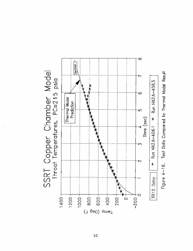
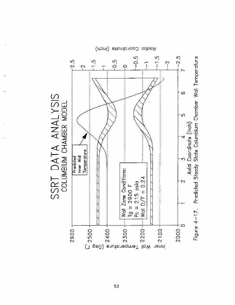
4.2.2 Thrust Chamber Thermal Analyses
Thermal analyses were conducted to assess the wall
temperatures of the thrust chamber using the high performance
tests with the -ii hybrid element. The results are shown in
Figures 4-16 and 4-17 which indicate a wall zone combustion
gas temperature of 2900°F. Using a columbium thrust chamber
coated with R512E silicide coating, the maximum temperature
is 2444°F (outside) and 2573°F (inside) which is slightly
upstream of the throat. The throat temperatures are 2553°F
45a

c6"o_E(i)
I-- "iii
(,-
0 F-
ro 40')
rr' ,-
rl'-I
a.)_L__
0")Jm
Ii
00
I
/
/
i
/
/ I
//
!
I" I
III
0 00 01.0 CO
I
4
II
[] :
I
(4) eJn:_eJeduJej.
46
LL
• 1
i
I
(I)
0")mm
[A.
//
x E0J r"
A 0 mI
!
o0
m
)0
'_" LO (0 i.O 0_1 I.O ",-- I.O 0 I.Oco o_ ,-- d c5
I
(oes/nls) MOl.-I 1EeH
47
0
(9) eJn_eJedwei
48
0(I)Z
1 I
OI>_
CO(/)
(i)L-
G) G)
\
0
CO
.(0
(..-I)eJn_,eJedwe.L
49

8
O
n-"
_o_tr
!
:D
la
LL
0-04
cO
0
(4) eJn],eJeduJe/
(D
t-O0G)CO
50

O
I
<O4<
E
n-
Om
LL
L5I
iT
LO _" CO
//
,,=,
T I
/\ I
m i
O I
\
A I _
, \I
E I0 I
O I
(- I
\\
I
0
\i
"l
(1)
Eoa
AIII
I,.,
(1).QE(.-0
0OJ
(X)
E)"iP-
_- (/)"0
0
(/)v
E-CO I--
-tO
,,_1-
Oa
0m
(oes/n3,8) MOl-! ;eeH
51
-C_u0"_
u_k__ _.-
(1) C'4
C" _
-.l--
k-. 12I
0___
I--- o
U')
I',
.............. 4 .............. i............... i------"
(.J _@CI) duJ@i
(J0O1@I
-F
E--]¢-y
(IJ
_j
E o
I
-I-
¢-
rY
+
w
m
.°
O
r-_
G
rY
-i--
Q)¢-y
111"IDO
oE
o
-o
o_
EoO
r_
td
I
i_
LI_
52
(qsu]) a.l.OU!p.4oo 3 IO!pOw
00
0 0 0 0 00 0 0 0 0U'3 '_ t'q _ ",--04 04 04 04 04
(_-I 6e(]) eJn.loJaduJa.L IIOM JaUUl
0
C30004
,-4
I
L
LL
53

Od
mI--
(..I
q..
E o
•r- ._.=q--4_q-- m
r" _.O
<
S-O
4-)O
e-o_.
OZ
A
"Q r--Or O_Ode.-
Or-e-
for--
(1) ¢'- 0f-- or- r_)
OE_
•-,_ ¢.-, ¢..--
O _ _--- ¢/)'l_ O _ X e"L; ¢;'¢_,-- O _-,- _ (i) 3:
"_ ¢- q- E ""_ _ -.- O e-
0o_..
o...
_P
q-
Qgc-O
Z
¢.-
000
(1)
mQu'l_l
C1. _.)
u')tO
"- :_¢./') ,,,_
-0 4_ ¢-"0 0 0
]=0
_- O_
o_ oF-
e- O'_-
_ ¢..) OO 4-_O _-
_- _rS- coO-O _,
OI:z VI --
._- ::_ r._
mm_E
>_.c:Qj.-O_-,- "os- v_ o_ m o
...J L_J ¢.._
O_t-
OO
E
u-
4_(J
E
¢-- ._
E ¢rS.- ¢'-
¢" _4.- ¢"
$...,--_ 6; O0Q _. "_"Q;
_r-.-X',- ¢_
•6-) .,-,-. ¢-- _..
E ._a ._.=O O _
(..) Cs. _"
e-S.- O
O
Eu_O
mS..r.-
O
4_
Eor-
o_u_ E6) _.-
q-Q; f.-
E
(a3Z
(I)
OO_ r- Ee- o
•,- vi -i_
o r_ ¢'-o r-_ O
o(1)=1 r--•_- r_ E O
I-- _-_ E I_
E5.-6)t-
Ooe-4_
"O
e- s-
(/1 e-(1) m
o_
A
Go_
=UE
r0 S-
(J (._O
E _
e- _
54

(inside) and 2410°F (outside). Therefore, the columbium
thrust chamber is the primary approach. Rhenium (iridium
coated internally) is the backup approach to the thrust
chamber design which may allow even higher performance.
55

5.0 EXPLORATORYTESTS
5.1 Design Approach
The engine design approach was to maximize design andoperational flexibility to allow cost effective evaluation ofthe range of engine parameters. The injector was designed tooffer flexibility in test to evaluate the changes necessaryto achieve high performance. The goal was to maximize testinformation for minimum cost. The TRWcoaxial injector wasideal for these evaluations as it allowed variations invelocity and geometry of the basic design to be readilytested and assessed.
The exploratory test engine utilized an injector whichallowed shimming of the oxidizer and fuel gaps to changevelocities and replaceable extensions to change fuelgeometry. The thrust chamber for this engine was a robustcopper heatsink thrust chamber using thermocoupleinstrumentation. The injector and thrust chamber were boltedtogether for ease of testing. Test stand valves were used atthis point in the program to eliminate the valve developmentprior to understanding the specific requirements andinterfaces. Pre and post test GN2 purges were used on allpropellants. Since the propellants were non-hypergolic, anigniter was required. The igniter used was N204 injectedthrough a port in the injector to ignite with the fuel priorto introduction of LO2. This concept was selected based onease of design and test.
5.2 Engine Design Point
The applications evaluation as discussed in 3.0 evaluated thevarious fuels and system requirements to maximize payloadinto orbit. The results indicated the system should bedesigned to the preliminary requirements of Table 3-12.Based on these preliminary requirements, the engine
preliminary requirements of Table 3-13 were developed and
provided the design point for the exploratory tests. These
requirements also provided the design for the test bed engine
as modified based on the exploratory test results.
5.3 Design Description and Fabrication
The TRW coaxial injector for the SSRT program was based on
the DM-LAE qualified and flying successfully on ANIK
satellites (E-I and E-2). These engines produce an average
specific impulse of 314.5 ibf-sec/ibm (£ = 204) and have
demonstrated almost 25,000 seconds operating life during
qualification with N204-N2H 4.
56
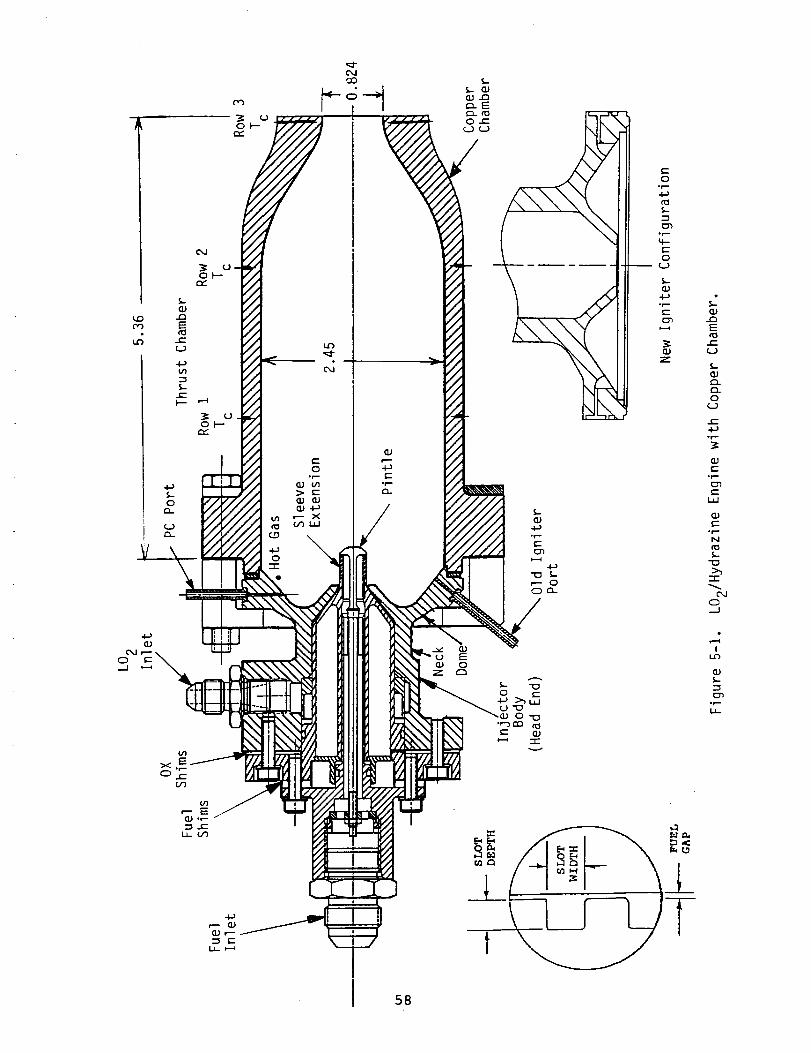
The SSRT injector consisted of the following elements:
• Body of columbium with aluminide coated face
(oxidation protection)
• Sleeve of 15-5 pH incorporating thermal isolation
of LO 2 and N2H 4• Pintle of 15-5 PH
• Extensions of 15-5 PH incorporating various slot
geometries
• Igniter to inject N204 to react with N2H 4 prior to
LO 2 injection.
The injector in the copper heatsink thrust chamber is shown
in Figure 5-1 and photographs of hardware are shown in Figure
5-2. Injector configurations are changed by replacing sleeve
extensions to assess variations in fuel slot geometry.
Additionally velocity changes can be varied by independently
shimming the oxidizer and fuel gaps. Six fuel geometries
were evaluated using five different configuration sleeve
extensions with the standard pintle. The highest performance
sleeve with a pintle incorporating three doublets (designated
hybrid) which bleeds fuel into the center of the engine was
tested to enhance performance. The slot configurationsvaried from 36-60 slots with slot widths of 8-16 thousands of
an inch and aspect ratios (slot depth/slot width) of
0.67-4.8. These wide variations in fuel geometry along with
variations in fuel gaps and oxidizer gaps provided the
ability to test over a range of large variations to assess
performance characteristics. This flexibility provided a
method to obtain affordable test costs with major geometry
changes in the injector.
The thrust chamber used during this basic program was a
robust heatsink copper chamber with type K thermocouplesbrazed into the wall at three axial locations and four
thermocouples at each station (90 ° apart). Thisinstrumentation allowed an assessment of the thermal
conditions of the thrust chamber.
5.4 Test Summary
5.4.1 Test Plan
As part of the SSRT basic program, exploratory hot fire tests
were defined to provide input to the engine design. These
tests were performed using the TRW IR&D hardware that wastested in 1990.
The exploratory tests performed in the basic program were
structured to provide basic engineering information relating
to the performance and thermal aspects of the design. Some
of the issues addressed were:
57
58
,2
E
{--(J
__r_0_J
_E4J
i,i
(-.
_J
._.1
Ii.r)
S.-
E_

\
ORIGINAL PAGE IS
OF POOR QUALITY
59

• Engine combustion performance characteristics
• Stable operation
• Engine thermal characteristics
• Injector characteristics
• Comparison of LO2/N2H 4 to hypergolic earth
storable propellants
• Ignition characteristics with N204• Hardware and system chill
Two test series were performed during the basic program. The
first series addressed the differences between the LO2/N_H 4propellant combination and the hypergolic propellant englnesusing the -8 fuel element. Also included in the first series
was testing of the -7 fuel element, which is the baseline 200
ibf thrust fuel element (see table 4-1).
A second test series was performed, incorporating hardwaremodifications based on the initial test series results.
Three new 200 Ibf equivalent fuel elements were evaluated in
this series, as was a modification to the injector pintle.
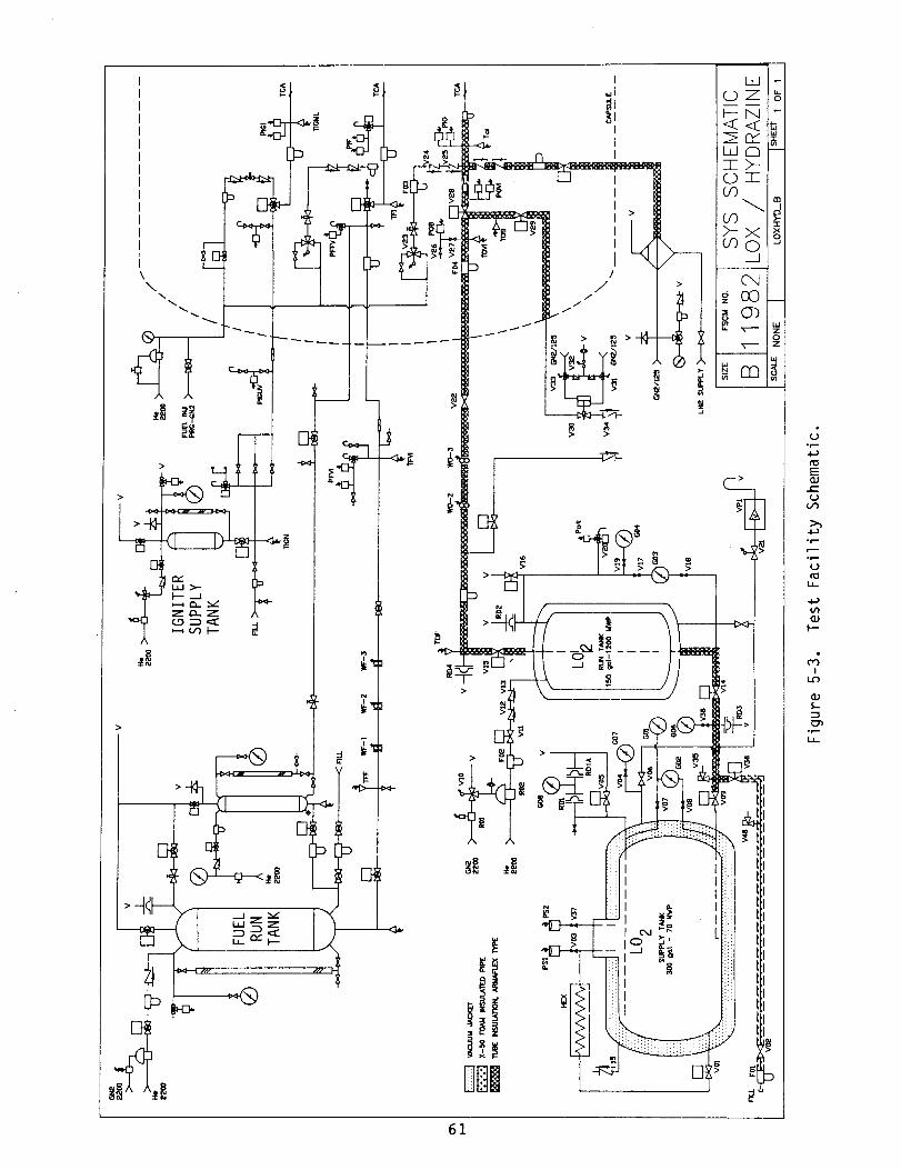
5.4.1.1 Test Facility
All hot fire testing of the SSRT engine in the basic program
was performed at TRW's Capistrano Test Site (CTS) Facility in
the HEPTS HA2A vacuum capsule. A facility schematic is shown
in Figure 5-3. A mechanical pumping system maintained the
test cell at less than 50 torr absolute pressure for all hotfire testing.
The fuel propellant tank was an 80 gallon hydrazine tank with
an outer glycol jacket that allowed thermal conditioning of
the propellant. Liquid oxygen propellant tankage included a
150 gallon run tank, fed from a 300 gallon LO 2 storage tank.
Both LO 2 tanks were vacuum insulated. The LO 2 in the run
tank was kept at its normal boiling point (-298F) by venting
the tank to atmospheric pressure between tests. LO 2propellant lines to the test capsule were insulated, and were
chilled prior to a test by bleeding LO 2 from the run tank to
the fire valve. The line downstream of the LO 2 fire valve
and the injector were pre-chilled by liquid nitrogen prior toeach test.
The igniter fluid was supplied by a small N204 tank and
controlled by a cavitating venturi. Propellant line heaters
were used on the fuel and igniter lines to prevent freezing
of the propellants during engine start-up. All propellant
lines were purged with GN2 during the start up and shutdown
transients. All valve timing was controlled by an IBM PC
based timer that allowed millisecond timing resolution of the
valve command signals.
60
[
I
ltI
iiii
½7-
,Z
:N
,ii
i
X'0
>--_
-!"2_
_J,r,-
E
e-
°r--
°r,-
LJ_
4-)
F'-"
_4!
61
5.4.1.2 Test Instrumentation and Data Recording
Performance evaluation of the SSRT engine was based on C*
performance measurements. Redundant instrumentation was used
on all performance related parameters, including propellant
flow rates, chamber pressure transducers, and venturi inlet
pressures. Cavitating venturis were used to control the flow
rates to the engine. These venturis have been water flowcalibrated. Three calibrated flowmeters in series were used
to measure the fuel flow rate. The oxidizer flow rate was
determined by use of a cavitating venturi.
Thermocouple instrumentation included 12 type K thermocouples
brazed into the copper chamber. Also, 12 thermocouples were
located at key locations on the injector to allow an
assessment of the thermal characteristics of the injector
head end. Other thermocouple instrumentation included
propellant temperatures at the flowmeters, venturi inlets and
engine inlets. An instrumentation list is presented in Table5-1.
Critical temperature measurements such as chamber and
injector dome temperatures were displayed on strip charts for
real time monitoring during testing. Early shutdown of a
test was determined by strip chart trends. Oscillograph
recording of critical parameters was available for quick look
and transient analysis of each test. All instrumentation was
recorded on digital tape and printed in numeric format for
data reduction analysis.
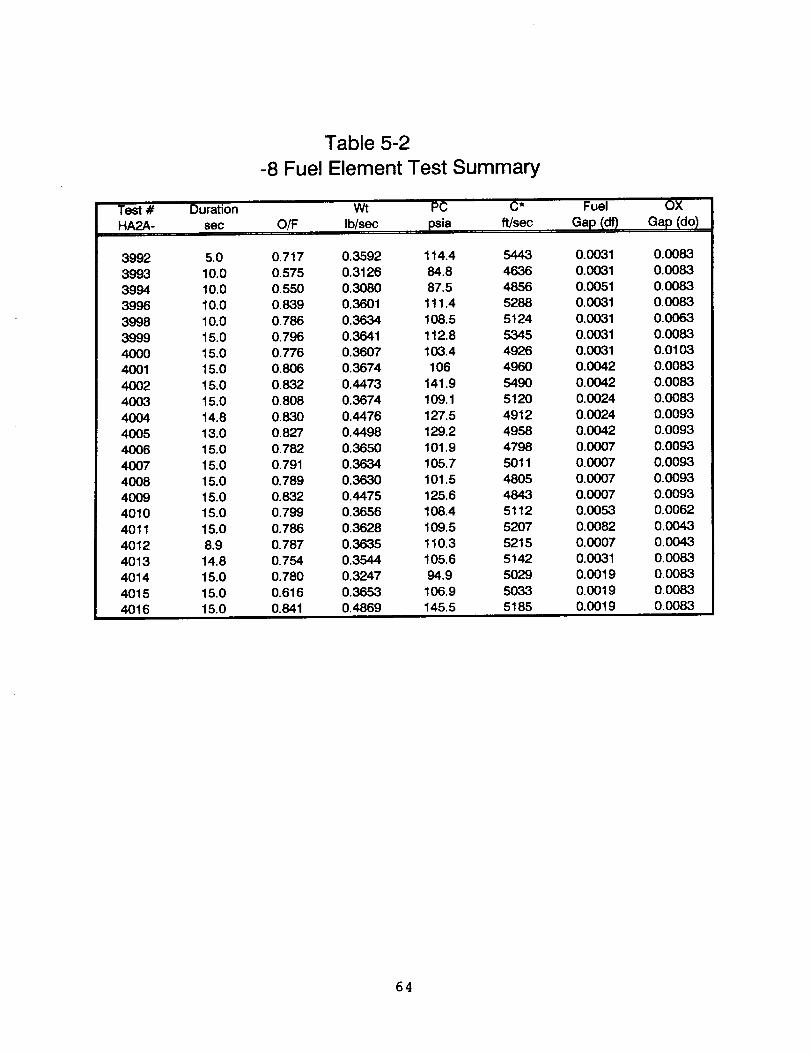
5.4.2 Test Summary of -8 Fuel Element
Initial hot fire testing of the SSRT engine was performed
with the -8 fuel element. This extension was designed based
on the TRW Dual Mode Liquid Apogee Engine (DM-LAE) fuel
geometry. The -8 element was designed to match the fuel
injection geometry and flow characteristics of the DM-LAE
engine as closely as possible. This allowed a direct
comparison of the operating trends of the non-hypergolic
LO2/N2H 4 propellant combination verses the well characterized
N204/N2H 4 propellant combination utilizd by the DM-LAEenglne. The nominal flow rate for this element was
established at an equivalent thrust of 125 ibf to match the
fuel injection characteristics of the DM-LAE engine.
Twenty-five tests were performed with the -8 element, ac-
cummulating 306.5 seconds of hot fire duration. The test
results for the -8 element are summarized in Table 5-2.
Performance of the element was approximately 83% C*
efficiency, compared to approximately 95% C* efficiency for
the DM-LAE Engine. Many of the DM-LAE performance trends
were non existent or not as clearly defined during testing of
the SSRT engine with the -8 element.
62

TABLE 5-1
SSRT INSTRUMENTATION LIST
ID
PC-I
PC-2
PIO-i
PIO-2
PID
PIF-I
PIF-2
POVI-I
POVI-2
PFVI-I
PFVI-2
WO-I
WO-2
WO-3
WF-I
WF-2
WF-3
TOF
TFF
TFI
TOI
TOVI
PIGT
PIGFV
PIGI-I
PIGI-2
TIGN
PA-I
PA-2
POT
PFT
TR-I
THRU
TR-12
TI-I
THRU
TI-12
TC-I
THRU
TC-16
ACCEL
RANGE
RECORD/DISPLAY
METHOD
S/C OSC DVM
0-300 PSIA X X X
0-300 PSIA
0-i000 PSIA X X
0-750 PSIA
0-500 PSIA
0-i000 PSIA X X
0-750 PSIA
0-i000 PSIA X
0-i000 PSIA
0-i000 PSIA X
0-i000 PSIA
0.15-0.30 LBM/S X X
0.15-0.30 LBM/S
0.15-0.30 LBM/S
0.20-0.40 LBM/S X X
0.20-0.40 LBM/S
0.20-0.40 LBM/S-350 to -200°F
40-100°F
40-100°F X
-350 to -200°F X
-350 to 60°F
0-i000 PSIA X
0-i000 PSIA
0-500 PSIA X X
0-500 PSIA
40-100_F
0-50 TORR X
0-50 TORR
0-i000 PSIA X
0-i000 PSIA X
0-2000°F Xi II I
O-2000°F X
-300-1000°F XI II I
-300-1000°F X
0-2500°F XI II I
0-2500°F X
0-i00 GS X
PARAMETER
CHAMBER PRESSURE
CHAMBER PRESSURE
OXID INLET PRESSURE
OXID INLET PRESSURE
OXID DISTRIBUTION PRESSURE
FUEL INLET PRESSURE
FUEL INLET PRESSURE
OX VENTURI INLET PRESSURE
OX VENTURI INLET PRESSURE
FU VENTURI INLET PRESSURE
FU VENTURI INLET PRESSURE
OXID FLOWRATE
OXID FLOWRATE
OXID FLOWRATE
FUEL FLOWRATE
FUEL FLOWRATE
FUEL FLOWRATE
OXID FEEDLINE TEMP
FUEL FEEDLINE TEMP
FUEL INLET TEMP
OXID INLET TEMP
OXID VENTURI TEMPERATURE
IGNITION TANK PRESSURE
IGNITION FIRE VALVE PRESS
IGNITION INLET PRESSURE
IGNITION INLET PRESSURE
INGITION INLET TEMP
CELL PRESSURE
CELL PRESSURE
OXID TANK PRESSURE
FUEL TANK PRESSURE
CHAMBER/NOZZLE TEMPSIi
CHAMBER/NOZZLE TEMPSINJECTOR TEMPS
INJECTOR TEMPS
TC PROBE TEMPSii
TC PROBE TEMPS
HEA ACCELEROMETER
*ALL PARAMETERS TO BE RECORDED ON DIGITAL TAPE.
63
-8 Fuel
Table 5-2
Element Test Summary
Test # Duration Wt PC C* Fuel OX
HA2A- sec O/F Ib/sec psia ft/sec Gap (o_ Gap (do)
3992 5.0 0.717 0.3592 114.4 5443 0.0031
3993 10.0 0.575 0.3126 84.8 4636 0.0031
3994 10.0 0.550 0.3080 87.5 4856 0.0051
3996 10.0 0.839 0.3601 111.4 5288 0.0031
3998 10.0 0.786 0.3634 108.5 5124 0.0031
3999 15.0 0,796 0.3641 112.8 5345 0.0031
4000 15.0 0.776 0,3607 103.4 4926 0.0031
4001 15.0 0.806 0.3674 106 4960 0.0042
4002 15.0 0.832 0.4473 141.9 5490 0.0042
4003 15.0 0.808 0.3674 109.1 5120 0.0024
4004 14.8 0.830 0.4476 127.5 4912 0.0024
4005 13.0 0.827 0.4498 129.2 4958 0.0042
4006 15.0 0.782 0.3650 101.9 4798 0.0007
4007 15.0 0.791 0.3634 105.7 5011 0.0007
4008 15.0 0.789 0.3630 101.5 4805 0.0007
4009 15.0 0.632 0.4475 125.6 4843 0.0007
4010 15.0 0.799 0.3656 108.4 5112 0.0053
4011 15.0 0.786 0.3628 109.5 5207 0.0082
4012 8.9 0.787 0.3635 110.3 5215 0.0007
4013 14.8 0.754 0.3544 105.6 5142 0.0031
4014 15.0 0.780 0.3247 94.9 5029 0.0019
4015 15.0 0.616 0.36,53 106.9 5033 0.0019
4016 15.0 0.841 0.4869 145.5 5185 0.0019
0.0063
0.0063
0.00830.0083
0.0063
0.00830.0103
0.0083
0.0083
0.0083
0.0093
0.0093
0.0093
0.0093
0.0093
0.0093
0.0062
0.0343
0.0043
0.0083
0.0083
0.0083
0.0083
64

Difficulties in obtaining single phase liquid oxygen flow to
the injector caused poor repeatability of the test data, and
resulted in no clear-cut performance trends with varying
injector parameters. The most significant factor affecting
performance was the amount of pre-chill to the injector and
LO run line bleed Injector pressure drops and discharge2coefficients on the oxidizer circuit varied by ±35% during
testing and averaged 20% lower than the oxidizer Cd measured
during water flow of the injector, indicating vapor
generation and two phase flow conditions.
Incomplete fuel vaporization was evidenced by the chamber
wall thermocouple data. Row 1 measurements showed a tendency
to operate near the fuel saturation temperature, indicating
liquid fuel impingement at the wall. Throat thermocouple
data also corresponded to a low wall zone mixture ratio.
Test durations for all -8 testing was limited by injector
dome redline temperatures (500F) rather than chamber
thermocouple redline (1000F).
The igniter for these tests was the same configuration tested
in the 1990 IR&D program; a single N204 stream directed
through the fuel spray pattern. This configuration caused a
high heat load to one side of the dome during the igniter
stage, resulting in a thermal maldistribution in the injectorat the start of the test.
On test HA2A-4002, a reaction of fuel and N204 in the igniterline (located at 6 o'clock) caused the line to rupture. The
engine was removed from the stand and a new igniter
configuration was employed. The old igniter port was welded
shut and two new ports, located 180 degrees apart (at 9 and 3
o'clock), were machined into the injector dome (see Figure 5-
1 for both configurations). These igniter ports created a
fine spray fan directed axially down the chamber, through the
fuel spray pattern. The ignition sequence with this igniter
configuration was improved, resulting in less thermal
maldistribution to the injector during ignition. The
original igniter would cause a thermal maldistribution of
approximately 100F during the ignition stage, while the new
configuration had a maximum maldistribution of approximately
30F. The igniter stage heat load to the injector was also
reduced for the new configuration.
5.4.3 Test Summary of 200 Ibf Elements
The remainder of the hot fire testing of the SSRT engine was
conducted with fuel elements designed for 200 ibf equivalent
flow rates. These elements( -7, -9, -i0 and -II) all have
equal slot flow areas, with the number of slots varying from
36 to 60. Performance was improved dramatically over the -8
fuel element, and test reproducibility and performance trend
definition was also better. The higher oxidizer flow rate
65
allowed a colder oxidizer inlet temperature, resulting infewer problems with vapor generation and two phase flowconditions. This was subtantiated by the 20% higher averageoxidizer Cd measured during the -7 testing as compared to the-8 element testing, and by the lower oxidizer Cd variation of±10% for the -7 compared to ±35% for the -8 element.
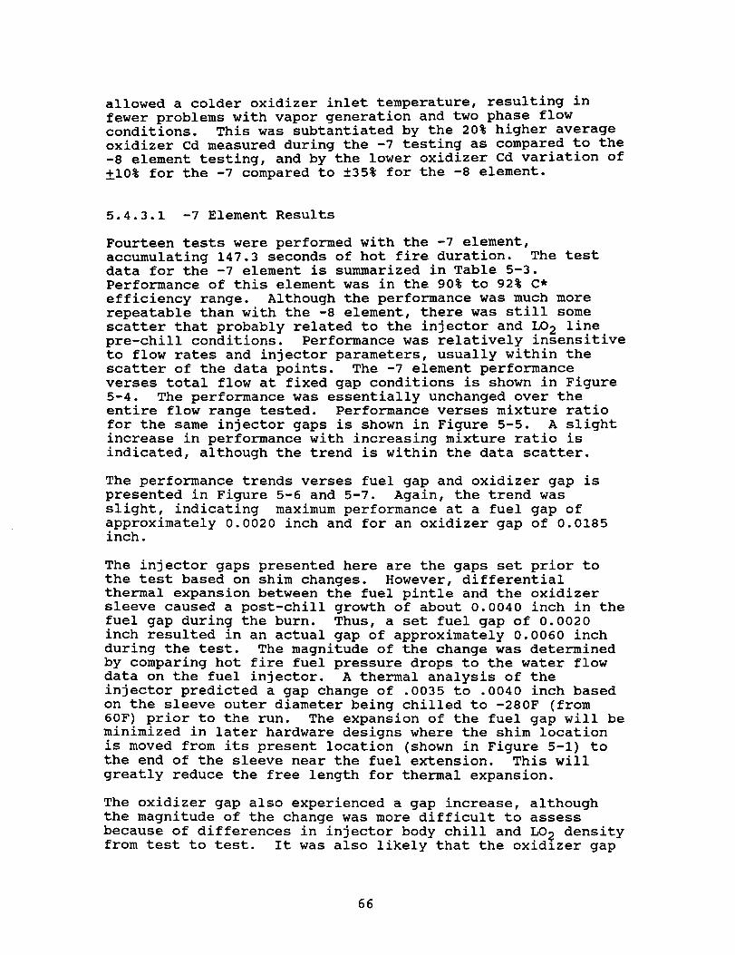
5.4.3.1 -7 Element Results
Fourteen tests were performed with the -7 element,accumulating 147.3 seconds of hot fire duration. The testdata for the -7 element is summarized in Table 5-3.Performance of this element was in the 90% to 92% C*efficiency range. Although the performance was much morerepeatable than with the -8 element, there was still somescatter that probably related to the injector and LO2 linepre-chill conditions. Performance was relatively insensitiveto flow rates and injector parameters, usually within thescatter of the data points. The -7 element performanceverses total flow at fixed gap conditions is shown in Figure5-4. The performance was essentially unchanged over theentire flow range tested. Performance verses mixture ratiofor the same injector gaps is shown in Figure 5-5. A slightincrease in performance with increasing mixture ratio isindicated, although the trend is within the data scatter.
The performance trends verses fuel gap and oxidizer gap ispresented in Figure 5-6 and 5-7. Again, the trend wasslight, indicating maximum performance at a fuel gap ofapproximately 0.0020 inch and for an oxidizer gap of 0.0185inch.
The injector gaps presented here are the gaps set prior tothe test based on shim changes. However, differentialthermal expansion between the fuel pintle and the oxidizersleeve caused a post-chill growth of about 0.0040 inch in thefuel gap during the burn. Thus, a set fuel gap of 0.0020inch resulted in an actual gap of approximately 0.0060 inchduring the test. The magnitude of the change was determinedby comparing hot fire fuel pressure drops to the water flowdata on the fuel injector. A thermal analysis of theinjector predicted a gap change of .0035 to .0040 inch basedon the sleeve outer diameter being chilled to -280F (from60F) prior to the run. The expansion of the fuel gap will beminimized in later hardware designs where the shim locationis moved from its present location (shown in Figure 5-1) tothe end of the sleeve near the fuel extension. This willgreatly reduce the free length for thermal expansion.
The oxidizer gap also experienced a gap increase, althoughthe magnitude of the change was more difficult to assessbecause of differences in injector body chill and LO2 densityfrom test to test. It was also likely that the oxidizer gap
66
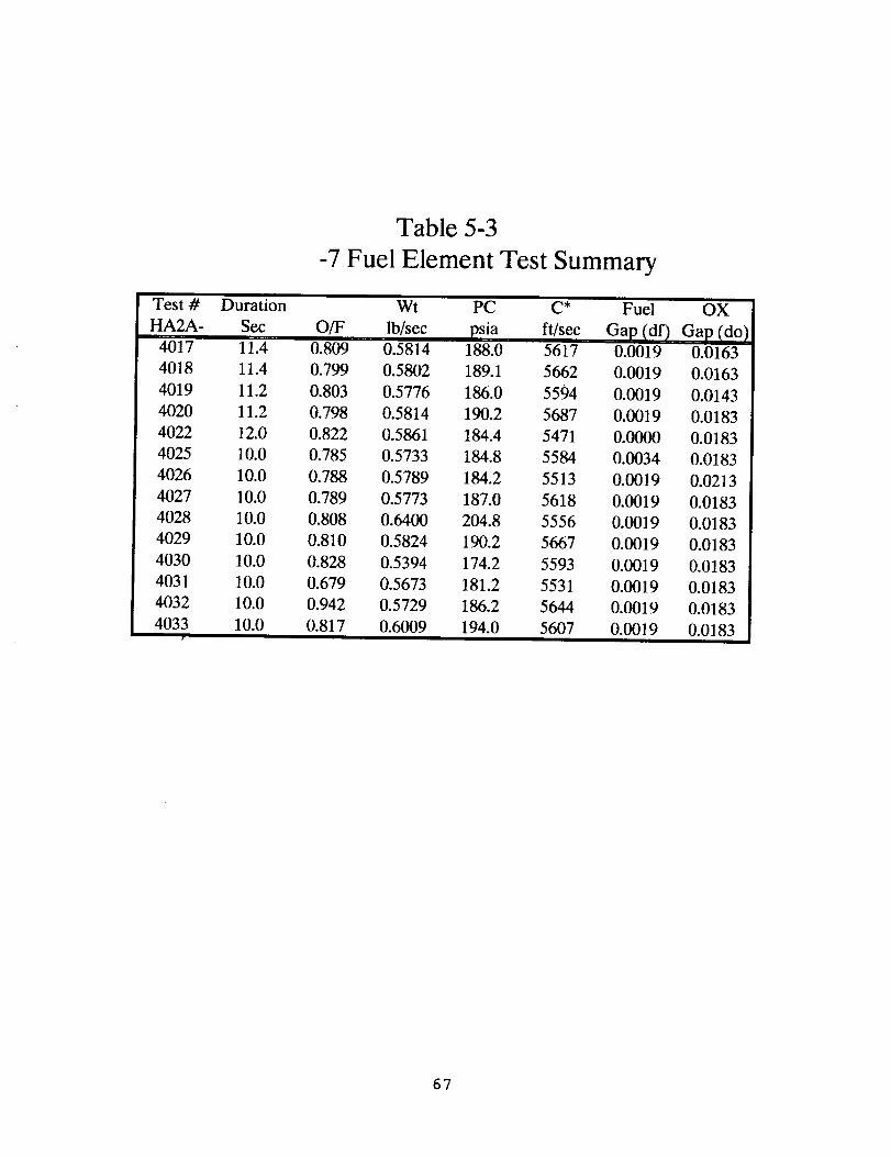
Test #
HA2A -
4017
4018
4019
4020
4022
4025
4026
4027
4028
4029
4030
4031
4032
4033
Table 5-3
-7 Fuel Element Test Summary
Duration Wt PC C* Fuel
Sec O/F lb/sec psia fVsec Gap (df)11.4 0.809 0.5814 188.0 5617 0.0019
11.4 0.799 0.5802 189.1 5662 0.0019
11.2 0.803 0.5776 186.0 5594 0.0019
11.2 0.798 0.5814 190.2 5687 0.0019
12.0 0.822 0.5861 184.4 5471 0.00013
10.0 0.785 0.5733 184.8 5584 0.0034
10.0 0.788 0.5789 184.2 5513 0.0019
10.0 0.789 0.5773 187.0 5618 0.0019
10.0 0.808 0.6400 204.8 5556 0.0019
10.0 0.810 0.5824 190.2 5667 0.0019
10.0 0.828 0.5394 174.2 5593 0.0019
10.0 0.679 0.5673 181.2 5531 0.0019
10.0 0.942 0.5729 186.2 5644 0.0019
10.0 0.817 0.6009 194.0 5607 0.0019
OX
Gap (do)
0.0163
0.0163
0.0143
0.0183
0.0183
0.0183
0.0213
0.0183
0.0183
0.0183
0.0183
0.0183
0.0183
0.0183
67
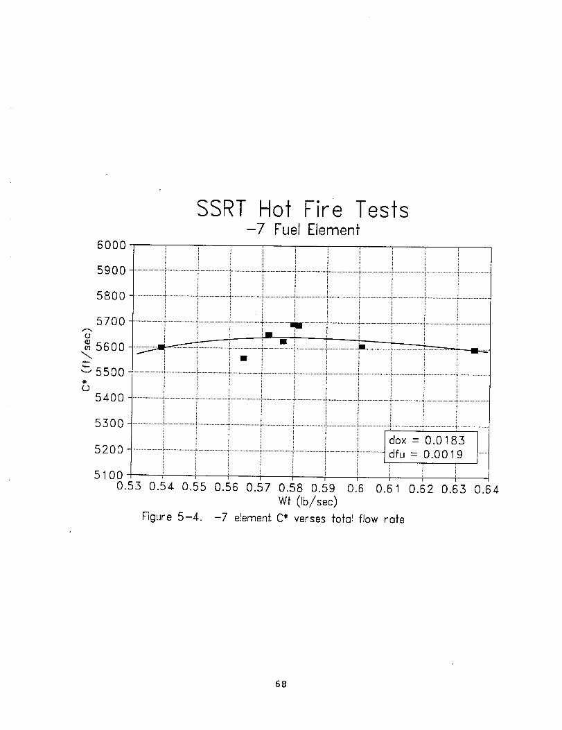
u
5600
"-'5500@
0
SSRT Hof Fire Tesfs-7 Fuel Elemenf
6000
5900 ..........................................................................................................................................................................................................i...................
5800 ........................................_................................................................................................................................................................._...................
5700 ........................................i...................................."....................... ................................................................................................_....................
5400
5300 .................................................................................................................................................................!............................................................dox = 0.0183 I
I
5200 ..............................................................................................................................................................dfu : 0.0019 I......
5100
0.53 0.54 0.55 0.56 0.57 0.58 0.59 0.6 0.61 0.62 0.63 0.64
wt Ob/sec)Figure 5-4. -7 element C* verses fofal flow role
68

6O0O
SSRT Hot Fire Tesfs-7 Fuel Elemenf
59O0
5800
5700
0
5600
_'5500
0
5400
550O
5200
5100
............................................................................................................ ......................................................................!..........................._.....- ' : -.............mS.........•--• ..........................................................................................
i dfu = 0.0019 ......{
0.65 0.7 0.75 0.8 0.85 0.9
Mixture Ratio (O/F)
Figure 5-5. -7 element C* verses mixture rotio
0.95
69

6000
SSRT Hot Fire Tests-7 Fuel Element
5900
5800
5700A
o
5600
"-" 5500
O
5400
5300
5200
5100
............................... i....................................................................................... • ....................................................................................................
• i r
................................................................................................................................J...d°L..-.°:°..:_.3.....!.?_t.h..........................
0 0.0005 0.001 0.0015 0.002 0.0025 0.003
Fuel Gap (inch)
Figure 5-6. -7 element fuel gap performance trend
0.0035
70
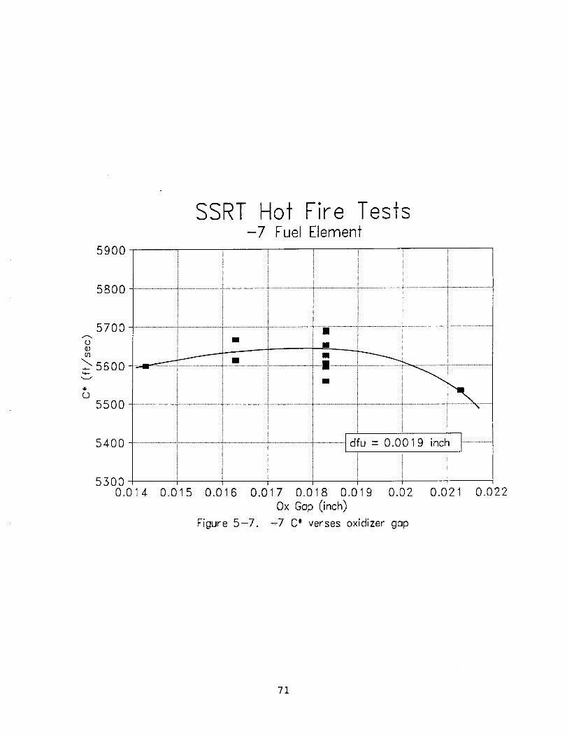
5900
SSRT Hof Fire Tesfs-7 Fuel Elemenf
58oo i
J5700 ...........................i.........................................................................................i ......................................................................................................
0©ol
_5600..,-
0
55O0
i I
5400 ...................................................................................................................................tdfu = 0.0019 inch
53OO0.014 0.015 0.016 0.0 7 0.018 0.019 0.C)2
Ox Gap (inch)
-.7 C* verses oxidizer gap
t ...................
Figure 5-7.
0.021 0.O22
71
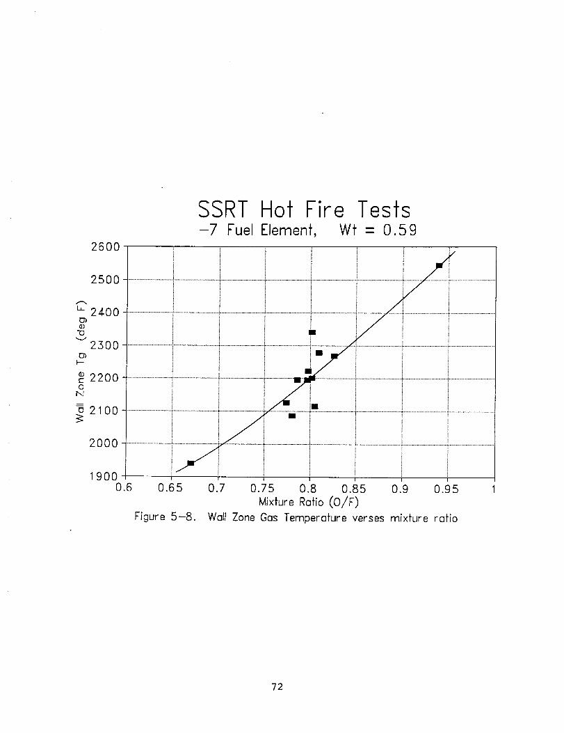
26O0
SSRT Hot Fire Tests-7 Fuel Element, Wf - 0.59
25O0
L 2400
©
2300
2200O
N
u 2100
2O0O
1900
i i _ " _;;...................i............................T...........................T............................
i i i -_ i i i............................i............................f ...........................f .................! .........................."............................÷...........................f............................
......................................................................................i...........................! ...............,..........•...................................................i...........................J.........................................
0.6 0.65
Figure 5-8.
0.7 0.75 0.8 0.85 0.9 0.95
Mixture Ratio (O/F)
Wall Zone Gas Temperature verses mixture ratio
72

was changing slightly during the test due to the injector
body warming up while the injector sleeve remained at the LO 2
temperature. Comparing test data to water flow data of the
oxidizer delta P indicates an average change in the oxidizer
gap of about 0.0020 inch during injector chill, which agrees
well with thermal analysis of the injector. With the dome
cooling concepts incorporated the oxidizer gap change should
be significantly reduced.
Chamber thermocouple data indicated a considerably higher
heat load to the chamber for the -7 element compared to the -
8. Throat thermocouples were reaching redline temperatures
of 1000F in Ii to 12 seconds for the -7 element, while they
were below 500F after 15 seconds duration for the -8 element.
A trend of increasing chamber heating rate for higher mixture
ratios is presented in Figure 5-8. A wall zone gas
temperature of about 2500F was calculated by comparing the
throat thermocouple data with predictions using the thermal
model of the copper chamber. This corresponded to a wall
zone mixture ratio of about 0.2, which indicated that steady
state operation with a columbium chamber with a comfortable
thermal margin is feasible.
5.4.3.2 Test Series Number 2: -9, -i0 and -ii Results
After testing and data analysis of the -7 element was
completed, three new elements, -9 through -ii, were designed
and built. These elements were based on the -7 geometry,
with modifications to some of the geometrical parameters (see
sections 5.3 and 4.1), with emphasis on increasing the fuel
vaporization rate.
All previous testing of the SSRT engine demonstrated that the
fuel element geometry was the primary factor in engine
performance. For all fuel element geometries tested,
the engine attained a certain level of performance, and only
secondary changes in performance were observed by changing
injector and flow parameters (aside from the detrimental
effects of two phase flow in the oxidizer circuit). Based on
this assessment, the test plan for the last three elementsincluded a limited number of tests for each element. If the
element tested didn't indicate increased performance in the
range of parameters covered by these tests, the assessment
was that no further gap or flow changes would make a
significant improvement in performance for that injector
geometry.
The hot fire testing performed with the -9, -i0 and -Ii
elements are summarized in Table 5-4. The performance trend
verses fuel gap for the three elements (-9, -i0 and -Ii) is
presented in Figure 5-9. This trend was similar to that
demonstrated by the -7 element, although the -II element did
perform better at larger fuel gaps than the other elements.
The -9 and -ii elements matched the -7 performance element
73
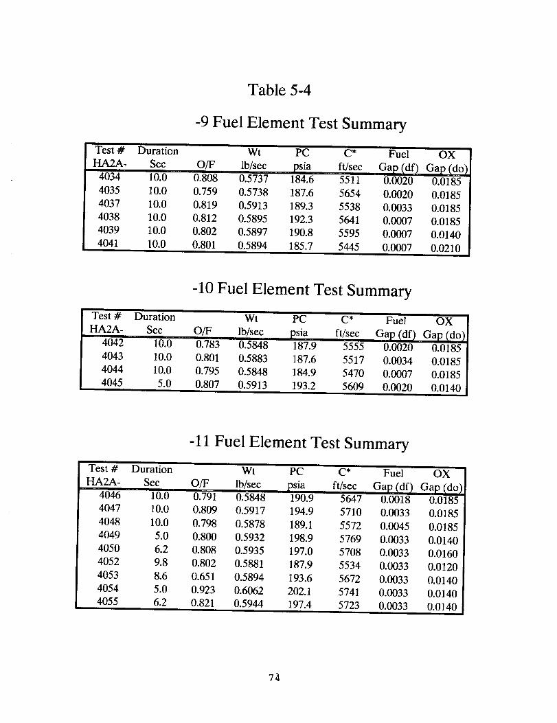
Table 5-4
-9 Fuel Element Test Summary
Test # Duration
HA2A- Sec OfF
4034 10.0 0.808'
4035 10.0 0.759
4037 10.0 0.819
4038 10.0 0.812
4039 10.0 0.802
4041 10.0 0.801
Wt PC C* Fuel
lb/sec psia ft/sec Gap (df /0.5737 184.6 5511 0.0020
0.5738 187.6 5654 0.0020
0.5913 189.3 5538 0.0033
0.5895 192.3 5641 0.0007
0.5897 190.8 5595 0.0007
0.5894 185.7 5445 0.0007
OX
Gap (_do/0.0185
0.0185
0.0185
0.0185
0.0140
0.0210
i
Test # Duration
HA2A- Sec
4042 10.0
4043 10.0
4044 10.0
4045 5.0
-10 Fuel Element Test Summary
Wt PC (_* Fuel
OfF lb/sec psia ft/sec Gap (df)0.783 0.5848 187.9 5555 0.0020
0.801 0.5883 187.6 5517 0.0034
0.795 0.5848 184.9 5470 0.0007
0.807 0.5913 193.2 5609 0.0020ii
OX
Gap (do)
0.0185
0.0185
0.0185
0.0140
Test # Duration
HA2A- Sec
4046 10.0
4047 10.0
4048 10.0
4049 5.0
4050 6.2
4052 9.8
4053 8.6
4054 5.0
4055 6.2
-11 Fuel Element Test Summaryi i
Wt PC C* Fuel OX
OfF Ib/sec psia ft/sec Gap (df) Gap (do)0.791 0.5848 190.9 5647 0.0018 0.0185
0.809 0.5917 194.9 5710 0.0033 0.0185
0.798 0.5878 189.1 5572 0.0045 0.0185
0.800 0.5932 198.9 5769 0.0033 0.0140
0.808 0.5935 197.0 5708 0.0033 0.0160
0.802 0.5881 187.9 5534 0.0033 0.0120
0.651 0.5894 193.6 5672 0.0033 0.0140
0.923 0.6062 202.1 5741 0.0033 0.0140
0.821 0.5944 197.4 5723 0.0033 0.0140
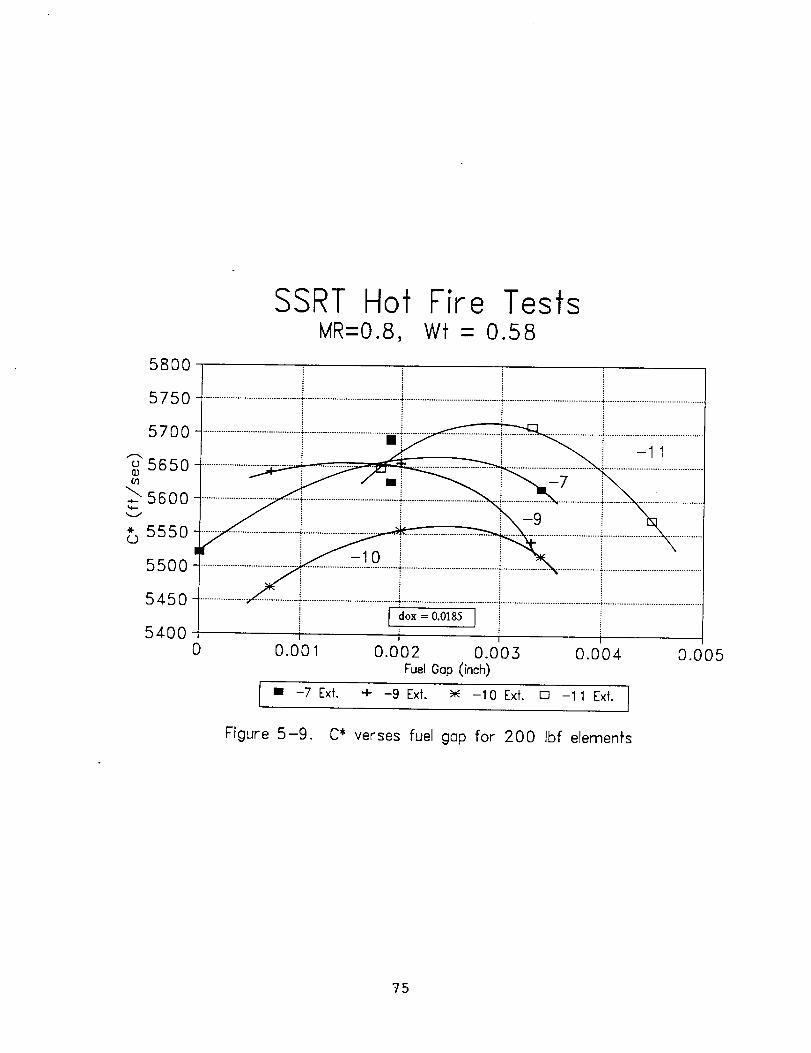
5800
SSRT Hot Fire TestsMR-O.8, Wf - 0.58
5750
5700
5650
56oo
* 5550
55O0
5450
540O
m_ i -11
{ d°x = 0"0185 I
i0 0.001 0.002 0.005 0.004 0.005
FuelOop(inch)
I • --7 Ext. + -9 Ext. _ -10 ExL [] -1 1 Ext.
Figure 5-9. C* verses fuel gop for 200 Ibf elemenfs
75

closely, but the -i0 element operated at a lower performance
level. This demonstrated that high slot aspect ratio was not
the key to higher performance.
The performance of the elements verses oxidizer gap at the
nominal flow conditions is shown in Figure 5-10. Once again
the -9 element showed the same performance trend as the -7,
preferring the 0.0185 oxidizer gap. The -i0 and -II elements
demonstrated higher performance at smaller oxidizer gaps.
The -ii element was tested at the 0.0120 inch oxidizer gap,
but the performance decreased dramatically at this condition.
Uneven injector dome heating and unsteady chamber pressure
during this test indicated that there may have been a problem
with the oxidizer injection distribution.
A mixture ratio survey was conducted with the -ii element at
the 0.0033 inch fuel gap and the 0.0140 oxidizer gap. The
results of this survey, Figure 5-11, indicated a trend of
increasing performance with mixture ratio, similar to the -7
element. Performance verses injector momentum ratio is shown
in Figure 5-12. A general trend of increasing performance
with higher momentum ratio was observed for all the elements,
with the exception of the test with highest oxidizer velocity(do = 0.0120) as discussed above.
Chamber heating rates for the -9 through -Ii elements were
very similar to the -7 element, but the injector dome heating
rate was very rapid with the -ii element, especially at
smaller oxidizer gaps. At a 0.0140 inch oxidizer gap andhigh mixture ratio, the injector dome reached the 500F red
line temperature in about five seconds. The dome thermal
distribution was uneven, with a higher heating rate on one
side of the injector.
5.4.3.3 -ii Hybrid Results
The combination of relatively low wall zone mixture ratio and
increasing performance trends at higher over all mixture
ratios led to the conclusion that the core combustion zone of
the engine was operating at a high mixture ratio. This
assessment was also confirmed by the Priem model of the
injector. A simple two-zone performance analysis indicated
that if the wall zone was at a mixture ratio of 0.2, the core
mixture ratio was approximately 1.3. Since the theoretical
optimum mixture ratio for this propellant combination is
approximately 0.73, the assessment was made that a
significant increase in performance could be gained if more
fuel could be directed into the core combustion zone,
decreasing the core mixture ratio toward optimum. This would
also result in increased performance at a lower over allmixture ratio.
Increasing the fuel flow to the combustion core zone was the
reasoning behind the hybrid injector. A spare pintle was
76

580O
5750
5700
o 5650
_5600-
5550
5500
5450
5400
SSRT Hot Fire TestsMR-0.8, Wf - 0.58
................................... 4-................................... ' ................................ _...................................................................... , ...................................
• - i
................................... i ................................... i .............................. • ........................................................................
...............5.......................... _ , . '!-7 .....................................................
i ....................................i...................................T................................._ ..................................
t I I
0.011 0.013 0.015 0.017 0.019 0.021 0.023
Ox Gap (inch)• -7 (df:.o019)
+ -9 (df:.O007) _ -10 (df:.O020) [] -11 (df:.O035) [
Figure 5-10. C* verses oxidizer gap for 200 Ibf elemenfs
77

5800
5750
(D
g3
_"L"5700'MI,,,-
"%-
(3
5650
560O
SSRT Hot Fire Tests-11 Element, Wf - 0.59
i............................................................................................................................ i ............................................................................................
i
i ]df = 0.0033 Ii do = 0.0140iI
06 0.65 0.7 0.75 0.8 0.85 0.9 0.95
Mixture Ratio (O/F)
-11 element C* verses mixture ratioFigure 5-11.
78
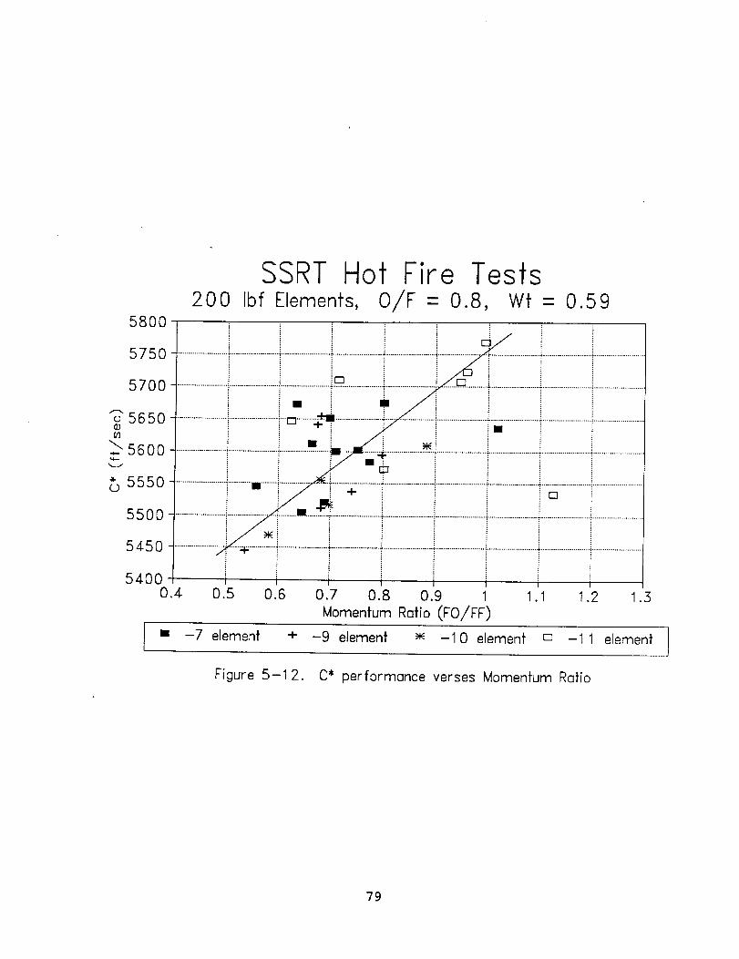
58OO
575O
570O
o 5650
_ 5600
555o
550O
545O
540O0.4
SSRT Hot Fire Tests200 Ibf Elements, O/F - 0.8, Wf - 0.59
0.5
I ........ i ...........
/I
0.6 .0.7 0.8 0.9
Momentum Ratio (FO/FF)
[]
1.2 1.3
• -7 element + -9 element -10 element [] -11 element I
Figure 5-1 2. C* performance verses Momentum Ratio
79

modified by drilling three like-on-like doublets into the
tip, yielding a hollow cone spray pattern oriented axiallydown the centerline of the chamber. Figure 5-13 shows the
pintle tip with the doublets installed. The doublets were
designed to direct about 10% of the total fuel flow into the
core. This pintle was tested with the -ii element, since
this element gave the highest performance.
The performance summary for the -ii hybrid injector is
presented in Table 5-5. C* efficiencies over 95% of
theroretical (ODK) were obtained, corresponding to a
projected vacuum Isp of >340 Ibf-sec/ibm. However, as
discussed below, problems with oxidizer injector delta P
variations prevented a complete characterization of the
injector.
The performance trend of the hybrid injector compared to the
basic -ii element tests is shown in Figure 5-14. At a
mixture ratio of 0.8, performance of the two injectors was
approximately equal. As the mixture ratio was decreased by
increasing the fuel flow rate, the performance of the hybrid
injector increased, producing the highest performance at a
mixture ratio of 0.70. Decreasing the mixture ratio even
further, however, caused variations in the oxidizer
delta P that resulted in operation at a lower performance
level. The onset of this condition appeared primarily at low
mixture ratios, even though the oxidizer flow conditions were
essentially unchanged from other higher mixture ratio testswhere the condition was not observed.
Post test examination of the oxidizer metering geometryrevealed a contour downstream of the minimum area that could
allow the oxidizer to diffuse to a lower velocity with
attendant pressure recovery. Apparently the attachment of
the oxidizer to this surface was not complete, resulting in
variations in the injection delta P. All future SSRT
injector hardware will incorporate modifications to the
oxidizer metering geometry to eliminate this condition.
The throat wall zone gas temperature verses momentum ratio
for all of the 200 ibf elements is presented in Figure 5-15.
This was derived from the chamber thermal model. The gas _
temperature increased with momentum ratio for all of the
elements except for the hybrid injector, where the data was
distorted by the oxidizer delta P variations discussed above.
The -7 element had the lowest gas temperatures at a given
momentum ratio, even though it had equivalent or even higher
performance than the -9 and -i0 elements.
Dome and chamber thermocouple heating rates during testing
with the hybrid injector were about 20% higher than with the
-ii element testing. This was expected, since the hybrid
pintle diverted some of the fuel flow from the wall zone to
the core, resulting in a higher wall zone mixture ratio. It
also created a higher effective momentum ratio (oxidizer to
8O

Test #
HA2A-
4056
4057
4058
4059
4060
4061
4062
4063
4064
4065
4066
4067
Table 5-5-11 Hybrid Element Test Summary
Duration Wt PC C*
Sec OfF lb/sec psia ft/sec5.4 0.794 0.5864 193.2 5672
5.0 0.724 0.6201 207.9 5769
7.8 0.796 0.5872 194.7 5732
5.0 0.733 0.6214 207.0 5739
6.6 0.712 0.6146 204.4 5743
7.2 0.702 0.6388 216.2 5858
7.4 0.674 0.6474 215.5 5764
5.8 0.728 0.6375 214.5 5807
8.8 0.685 0.6588 210.1 5531
8.2 0.717 0.6424 204.9 5510
6.2 0.720 0.5902 196.5 5737
9.8 0.675 0.5931 193.4 5613
Fuel
Gap (df)0.0033
0.0033
0.0010
0.0010
0.0021
0.0021
0.0021
0.0021
0.0021
0.0033
0.0021
0.0021
OX
Gap (do)0.0140
0.0140
0.0140
0.0140
0.0140
0.0140
0.0140
0.0140
0.0140
0.0140
0.0140
0.0140
81
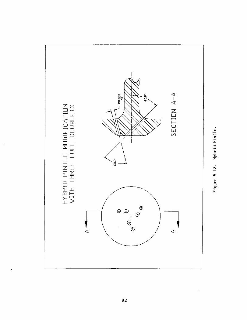
Z_
_W
LO
Eli__]IW
DWL
_WZW
O- I
nxI
I
\NI
\ / i
<'40
<11I
<[
Zr-lI----.t
(_DWCO
<[
e-Qr.-
°r.,-
L,.Q
-r-
'7
.%-
of...
I..L
82
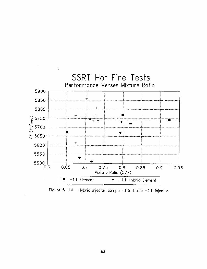
5900
SSRT Hot Fire TestsPerformance Verses Mixture Ratio
5850 .............................................................._ ..........................................................................................................................................................
5800 ...............................................................................* .............................................................................................................................................
÷ ÷ n
5750 ....... i................................................ _+ ¥ +i •
5700
8 5650 .................................................................................................................................................................................................................................+
5600 .................................................................................................................................................................................................................................
5550 1............................................................................................................................................................................................................................+5500 +
O.E 0.65 0.7 0.75 0.8 0.85 0.9 0.95
Mixture Ratio (O/F)
I • -11 Element + -11 Hybrid Element I
Figure 5-14. Hybrid injector compared to basic -11 iniecfor
83

30002900
_2800L
2700
2600
2500
e 2400co 2300
N
= 2200o
2100
2000
19000.4
SSRT Hot Fire TestsChamber Thermal Environment
........................-..........................-...................._-...×................!..............x...x-............__ .........._.....................=.........................i i +i i i ..._-_ xJ i
........................t.........................;........................,':......................_- ............._--_ .............".........._..................................................
........................t........................"..........................:........................".:................t...................._..........................:.........................i........................
............................'.......................'__'i-_-_.......................T........................T.........................i.....................i_..................i.........................i.........................
...............! ! .....-"_...................!..........=.........!........................t........................_.........................i.........................
........................._-.-:_-=........i........................_........................i.........................i........................"........................i.........................i.........................I I
0.5 0.6 0.7 0.8 0.9 1 .I 1.2 1.3
Momentum Rofio (FO/FF)
• -7 element + -9 element
[] -11 element x -11 hybrid
-10 element
Figure 5-15. Wall Zone Gas Temperature verses momentum ratio
84

fuel) at the primary impingement point, which caused a hotter
dome heating condition. As discussed in section 4, analysis
of thermocouple data from the highest performing tests (HA2A-
4061 and 4063) indicated that operation with a columbium
thrust chamber at a maximum steady state temperature of 2500Fis feasible.
The heat load to the injector during testing with the -ii
hybrid element was too high to allow steady state operation
of the engine in the current configuration (see section
4.2.1). Analysis indicated that the oxidizer will experience
film boiling in the injector, leading to an unacceptable
thermal condition. Additional work is needed with injector
cooling concepts to reduce the heat load into the oxidizermain flow.
Post test hardware condition was excellent, with no signs of
excessive heating or distortion. The copper chamber was in
excellent condition, with no signs of damage or erosion.
5.5 Test Conclusions
Overall, the exploratory test series of the SSRT was very
successful. A total of 76 tests was performed, accumulating
over 700 seconds of hot fire duration. The performance goal
of a vacuum specific impulse (Isp) of >340 ibf-second/Ibm
(E = 204) was demonstrated, while maintaining a wall
environment compatible with long duration operation of a
radiation cooled columbium thrust chamber. The thermal load
to the injector was defined, yielding information for the
design of a thermally adequate injector in the next program
option. Reliable ignition and stable operation of the enginewas demonstrated.
Testing of an injector fuel element geometry that yielded
high performance with hypergolic propellants resulted in a
lower level of performance with the LO2/N2H 4 combination.Significant differences in operating charac£eristics between
the hypergolics and LO2/N2H 4 were observed. Also, it was
found that operation at lower flow rates (F = 125 ibf)
resulted in difficulties in attaining single phase liquid
oxygen flow to the engine.
Testing at the 200 Ibf thrust equivalent flow rate allowed
more control over the LO_ inlet temperature, allowing singlephase flow and improved injector cooling for short duration
testing. The results of the testing with five 200 ibf
injector element configurations indicated that the fuel
element geometry is the primary performance driver for this
engine. The engine was relatively insensitive to other
injection parameters such as total flow and injection
velocities, especially compared to the hypergolic engines.
85
The results of the testing indicated that an increased numberof fuel slots resulted in highest performance. The smallerslots produced a finer drop size, resulting in bettervaporization of the fuel.
Although significant accomplishments were achieved in thistest series, additional development is required. A method ofcooling the injector to allow steady state thermal operationof the engine is required. The impacts of the injectorcooling approach on performance must be assessed. Moreextensive performance mapping of the injector is required, aswell as the demonstration of long duration operation.
86

6.0 TEST PLANS
A preliminary logic plan was developed for option 1 of theSSRT Program. This logic plan is shown in Figure 6-1.
6.1 Option 1
The major emphasis on the Option 1 program is evaluation ofof the most promising methods of dome cooling fordetermination of the effectiveness of these concepts andtheir impact on performance and thrust chamber walltemperatures. A preliminary design of the injectorintegrating the cooling concept for generation of maximumperformance will be accomplished at the conclusion of OptionI.
New injector hardware will be designed using a thermallyisolated dome. This dome is designed to have the capabilityof using replaceable auxiliary sections incorporating thermalblockage and film cooling dome cooling concepts.
Pintle, sleeve, oxidizer gap and fuel gap changes areincorporated into the injector design similarly to the Basicprogram design. This injector is designed and manufacturedto allow for wide flexibility of testing in a cost effectivemanner. In addition a study will be conducted to assessignition methods so it can be incorporated into thepreliminary design.
Testing will be accomplished in the same test cell as theBasic program tests (HA2A). The preliminary logic matrix ispresented in Figure 6-2. The detailed test plan will beprepared upon completion of design. The test program isconfigured to obtain the data required to determine the domecooling concept for integration into the Option 2 injector.The test program will utilize two injector elements and testvarying oxidizer (_o) and fuel (6f) gaps and mixture ratio(O/F) and total flow (WT). Analysis of the test data withcorrelations of performance and thermal considerations willbe generated to allow an understanding for further design andtest.
A preliminary design of an injector integrating the bestcooling concept and the high performance mechanisms will beaccomplished by the completion of the Option 1 program. Thebasis of the Option 2 detailed design will be provided bythis preliminary design developed based on the test resultsof Option i.
87

,--tI
_O
O_
C.)I--4
0
0
_r_
T
I--
L.I- -t- v
L_JZ _r"
'-,r-
zc_
0 _--I.L ,',"
l.LI -r-" I'-"
LLI Z )'-(
Z._IO'_ C:) 0_" 0 ¢.--)
0,, ,,,_
LLI 0 "r"
Z0
I__ (,/')_z
L.LI L.I_I U..I
I-- I---ZZL_L_
_.,._
x _-,
zI_LI
0,:_0 _-
0L._ I.I-
OL_
I.---
_. 0")
' t'---
r._)Z
_" ..__r_:_0 _-
_" L.LIt.LI "t-O.- I---
'lr...Oz
t._ Z )--(
I.-- Z.-IO,_00_" C_ r.__
I-.. m_'o0,, ,,,_
88

,'-_uJI.LI,m,_
F-- ,'--,_
r-_
,',4.._ >.-Z
(._)._..o,.-_C",d
O_ I I
C3
0 A
-,-t
-,-t
"'- Z_' 0
E_
0
z
>-z
r-.t ,r--i! !
i
I_--_ ZUJ'_ ___.1_--, I--
___ ._1 _. JLL_ (_-- I---J
_w>.-z'n'-v
•T "7 "_
I-- 4-- I_ 4- _I_
b- 0
¢-_ 0r-- 0r-- 0
I ° e--r-• 4,_ •
-,-- c._ ,'-I',- _
89

7.0 CONCLUSIONS
Several conclusions were reached as a result of completion of
the basic SSRT program.
• The greatest potential usage for the Space Storable engine
is utilization as an advanced dual mode apogee/perigee
engine in a dual mode propulsion system for placement and
maintenance of satellites in GEO. The best propellant
combination to achieve this usage is LO2-N2H4 as itprovides the best system/engine capability including
maximization of payload into orbit and achieved the best
overall rating of the characteristics of the fuelsevaluated.
• Thermal and performance analyses indicated that high
performance of 340 ibf-sec/ibm (£ = 204) could be achieved
with operation in a columbium thrust chamber.
• Testing confirmed the analyses. Six injector geometries
indicated the need to redesign the injector dome to prevent
two-phase LO 2. The testing demonstrated that highperformance (95% C*) (Isp _ 340 ibf-sec/ibm with £ = 204)
could be achieved and that operation in a columbium thrustchamber is feasible. The use of a rhenium thrust chamber
is another alternative which would allow even higher
performance (approaching 97% C* to yield Isp -- 350
ibf-sec/ibm).
9O

8.0 RECOMMENDATIONS
The major recommendation based upon the basic program resultsis to continue the development of the LO2-N2H4 Space Storableengine with Option i. The emphasis on the Option 1 programis resolving the dome heating issues by incorporating domecooling concepts and evaluation of these concepts by test todetermine cooling capability and its impact on performance.Ignition concepts should also be studied to determine theconcept to be incorporated into the integrated injector ofOption 2. The output of the Option 1 program should be thepreliminary design of the best cooling concept in theinjector providing maximum performance.
The recommendations for the Option 2 and Option 3 programsare to complete development of the Space Storable engine toallow verification and qualification beyond Option 3. Therecommendation for the Option 2 program is to develop theintegral injector incorporating high performance and domecooling and demonstrate its characteristics by test. Theresults of the Option 2 program are factored into Option 3.The recommendation for the Option 3 program is to develop aflight-type engine and demonstrate its characteristics bytest prior to shipment to NASA-LeRC.
91

Form ApprovedREPORT DOCUMENTATION PAGE OMBNo.0704-0188
Public tel)orang burden lot this collection of infom_ation is es_mated to average 1 hour per response, including fide time for rewewing insDl.c'dons, searching exlsling data so_ces.galhenng and maintaining the dala needed, and completing and reviewing 81e coflec_on of inlo(malJon. Send comments regarding this burden esth'nate of Imy other aspecl of thiscolleclJon of inlorma_on, incJuding suQgesgons lo¢ reducing this burden, to Washington Headquarters Sm-,nces, DireCtOrate for into_nabon Operations and Reports, 1215 JelfersonDavis Highway. Suite 1204, Arlington. VA 22202-4302, and to the Office of Management and Budget. Papenvork Reduction Prolect (0704-0188). Washington, DC 20503.
1. AGENCY USE ONLY (Leave blank) 2. REPORT DATE
12 May 19924. TITLE AND SUBTITLE
Space Storable Rocket TechnologyFinal Report - Basic Program
S. AUTHOR(S)
Melvin L. ChazenThomas Muell er
A. Ramon Casillas
David Huang
7. PERFORMINGORGANIZATIONNAME(S)ANDADDRESS(ES)TRW Space & Technology GroupApplied Technology DivisionOne Space ParkRedondo Beach, CA
9. SPONSORING/MONITORING AGENCY NAMES(S) AND ADDRESS(ES)
National Aeronautics and Space Administration
Lewis Research Center
Cleveland, Ohio 44135 - 3191
; 3. REPORT TYPE AND DATEj_ COVERED
Final Contractor Report
5. FUNDING NUMBERS
_tTV_ -
Contract NAS 3-26246
8. PERFORMING ORGANIZATION
REPORT NUMBER
E- None
10. SPONSORING/MONITORING
AGENCY REPORT NUMBER
NASA CR- 189131
11. SUPPLEMEWrARYNOTESProject Manager - Mr. James A. Biaglow
Space Propulsion Technology DivisionNASA-Lewis Research Center
12a. DISTRIBUTION/AVAILABILITY STATEMENT
Unclassified - Unlimited
Subject Category -__ c
12b. DISTRIBUTION CODE
13. ABSTRACT (Maximum 200 words)
The Space Storable Rocket Technology Program (SSRT) was conducted for NASA-LeRC byTRW to establish a technology base for a new class of high performance and long-lifebipropellant engines using space storable propellants. The results of the initialphase of this systematic multi-year program are described. Task 1 evaluated severalcharacteristics for a number of fuels to determine the best space storable fuel for
use with LO2. The results of this task indicated that LO2-N2H 4 is the bestpropellant combination and provides the maximum mission/system capability-maximumpayload into GEO of satellites. Task 2, Preliminary Design, developed two models-performance and thermal. The performance model indicated the performance goal ofspecific impulse > 340 seconds (_ = 204) could be achieved. The thermal model wasdeveloped and anchored to hot fire test data. Task 3, Exploratory Test, consistedof design, fabrication and testing of a 200 Ibf thrust test engine operating at achamber pressure of 200 psia using LO2-N2H 4. A total of 76 hot fire tests wereconducted demonstrating performance > 340 seconds (_ = 204) which is a 25 secondspecific impulse improvement over the existing highest performance flight apogee typ_engines.
14. SUBJECT TERMS
Rocket engines, Satellite propulsion, Bipropellant engines,Space storable, High performance engines, Long life engines.
17. SECURITY CLASSIFICATION 18. SECURITY CLASSIFICATION
OF REPORT OF THIS PAGE
Unclassified Unclassified
NSN 7540-01-280-550092
19. SECURITY CLASSIFICATION
OF ABSTRACT
Unclassified
15. NUMBER OFPAGES
16. PRICE CODE
A0520. LIMITATION OF ABSTRACT
SAR
Standard Form 298 (Rev. 2-89)
Prescribed by ANSI Std. Z39-18298-102