space product assurance - esmat.esa.intesmat.esa.int/ecss-q-70-26a.pdf · ecss 13 february 2001...
TRANSCRIPT

FOR SPACE STANDARDIZATION
EUROPEAN COOPERATION
ECSS
Space productassurance
Crimping of high-reliability electricalconnections
ECSS SecretariatESA-ESTEC
Requirements & Standards DivisionNoordwijk, The Netherlands
ECSS-Q-70-26A13 February 2001

ECSS13 February 2001ECSS--Q--70--26A
2
Published by: ESA Publications DivisionESTEC, P.O. Box 299,2200 AG Noordwijk,The Netherlands
ISSN: 1028-396X
Price: � 10
Printed in The Netherlands
Copyright 2001 E by the European Space Agency for the members of ECSS

ECSS 13 February 2001
ECSS--Q--70--26A
3
Foreword
This Standard is one of the series of ECSS Standards intended to be appliedtogether for the management, engineering and product assurance in spaceprojects and applications. ECSS is a cooperative effort of the European SpaceAgency, national space agencies and European industry associations for thepurpose of developing and maintaining common standards.
Requirements in thisStandardare defined in termsofwhat shall be accomplished,rather than in terms of how to organize and perform the necessary work.
This Standard has been prepared by editing ESA PSS 01--726, reviewed by theECSS Technical Panel and approved by the ECSS Steering Board.

ECSS13 February 2001ECSS--Q--70--26A
4
(This page is intentionally left blank)

ECSS 13 February 2001
ECSS--Q--70--26A
5
Contents
Foreword 3. . . . . . . . . . . . . . . . . . . . . . . . . . . . . . . . . . . . . . . . . . . . . . . . . . . . . . . . .
Introduction 9. . . . . . . . . . . . . . . . . . . . . . . . . . . . . . . . . . . . . . . . . . . . . . . . . . . . . .
1 Scope 11. . . . . . . . . . . . . . . . . . . . . . . . . . . . . . . . . . . . . . . . . . . . . . . . . . . . . . . .
2 Normative references 13. . . . . . . . . . . . . . . . . . . . . . . . . . . . . . . . . . . . . . . . .
3 Terms, definitions and abbreviated terms 15. . . . . . . . . . . . . . . . . . . . . . .
3.1 Terms and definitions 15. . . . . . . . . . . . . . . . . . . . . . . . . . . . . . . . . . . . . . . . . . . . . . .
3.2 Abbreviated terms 15. . . . . . . . . . . . . . . . . . . . . . . . . . . . . . . . . . . . . . . . . . . . . . . . .
4 Preparatory conditions 17. . . . . . . . . . . . . . . . . . . . . . . . . . . . . . . . . . . . . . . .
4.1 Hazards, health and safety precautions 17. . . . . . . . . . . . . . . . . . . . . . . . . . . . . . .
4.2 Configuration of process and workpiece 17. . . . . . . . . . . . . . . . . . . . . . . . . . . . . .
4.3 Facilities 18. . . . . . . . . . . . . . . . . . . . . . . . . . . . . . . . . . . . . . . . . . . . . . . . . . . . . . . . . .
4.4 Tools and equipment 18. . . . . . . . . . . . . . . . . . . . . . . . . . . . . . . . . . . . . . . . . . . . . . .
ECSS13 February 2001ECSS--Q--70--26A
6
5 Crimping operations 21. . . . . . . . . . . . . . . . . . . . . . . . . . . . . . . . . . . . . . . . . .
5.1 Forms of crimp 21. . . . . . . . . . . . . . . . . . . . . . . . . . . . . . . . . . . . . . . . . . . . . . . . . . . .
5.2 Workmanship 22. . . . . . . . . . . . . . . . . . . . . . . . . . . . . . . . . . . . . . . . . . . . . . . . . . . . .
5.3 Workmanship standards 28. . . . . . . . . . . . . . . . . . . . . . . . . . . . . . . . . . . . . . . . . . . .
6 Test method 29. . . . . . . . . . . . . . . . . . . . . . . . . . . . . . . . . . . . . . . . . . . . . . . . . .
6.1 General 29. . . . . . . . . . . . . . . . . . . . . . . . . . . . . . . . . . . . . . . . . . . . . . . . . . . . . . . . . .
6.2 Voltage-drop 29. . . . . . . . . . . . . . . . . . . . . . . . . . . . . . . . . . . . . . . . . . . . . . . . . . . . . .
6.3 Tensile strength 30. . . . . . . . . . . . . . . . . . . . . . . . . . . . . . . . . . . . . . . . . . . . . . . . . . . .
6.4 Metallography 32. . . . . . . . . . . . . . . . . . . . . . . . . . . . . . . . . . . . . . . . . . . . . . . . . . . .
7 Acceptance criteria 33. . . . . . . . . . . . . . . . . . . . . . . . . . . . . . . . . . . . . . . . . . .
7.1 Validation and qualification testing 33. . . . . . . . . . . . . . . . . . . . . . . . . . . . . . . . . . .
7.2 Shift performance test 34. . . . . . . . . . . . . . . . . . . . . . . . . . . . . . . . . . . . . . . . . . . . . .
8 Quality assurance 35. . . . . . . . . . . . . . . . . . . . . . . . . . . . . . . . . . . . . . . . . . . . .
8.1 General 35. . . . . . . . . . . . . . . . . . . . . . . . . . . . . . . . . . . . . . . . . . . . . . . . . . . . . . . . . .
8.2 Data 35. . . . . . . . . . . . . . . . . . . . . . . . . . . . . . . . . . . . . . . . . . . . . . . . . . . . . . . . . . . . .
8.3 Nonconformance 35. . . . . . . . . . . . . . . . . . . . . . . . . . . . . . . . . . . . . . . . . . . . . . . . .
8.4 Calibration of crimping tools 37. . . . . . . . . . . . . . . . . . . . . . . . . . . . . . . . . . . . . . . .
8.5 Requirements for new crimp configurations 38. . . . . . . . . . . . . . . . . . . . . . . . . . .
8.6 Traceability 39. . . . . . . . . . . . . . . . . . . . . . . . . . . . . . . . . . . . . . . . . . . . . . . . . . . . . . .
8.7 Personnel training 39. . . . . . . . . . . . . . . . . . . . . . . . . . . . . . . . . . . . . . . . . . . . . . . . . .
8.8 Inspections 40. . . . . . . . . . . . . . . . . . . . . . . . . . . . . . . . . . . . . . . . . . . . . . . . . . . . . . .
Figures
Figure 1: Confined irregular-octagon crimp (compactive) 21. . . . . . . . . . . . . . . . . . . . . . . . . .
Figure 2: Dimpled confined octagon crimp (compactive) 21. . . . . . . . . . . . . . . . . . . . . . . . . .
Figure 3: Regular-hexagon crimp (compactive) 22. . . . . . . . . . . . . . . . . . . . . . . . . . . . . . . . . . .
Figure 4: Semicircular one- or two-indent crimp (dispersive) 22. . . . . . . . . . . . . . . . . . . . . . . . .
Figure 5: Four-indent crimp (dispersive) 22. . . . . . . . . . . . . . . . . . . . . . . . . . . . . . . . . . . . . . . . . . .
Figure 6: Example of a typical connector barrel and single wire crimping 23. . . . . . . . . . . . .
Figure 7: Example of a typical connector barrel and multi-wire crimping 25. . . . . . . . . . . . . .
Figure 8: Example of a typical ferrule shield crimping 26. . . . . . . . . . . . . . . . . . . . . . . . . . . . . .
Figure 9: Typical test fixture for testing lug and splice crimps 27. . . . . . . . . . . . . . . . . . . . . . . . .
Figure 10: Examples of typical lug and splice wire crimping 27. . . . . . . . . . . . . . . . . . . . . . . . .
Figure 11: Workmanship examples and crimp microsections 28. . . . . . . . . . . . . . . . . . . . . . . .

ECSS 13 February 2001
ECSS--Q--70--26A
7
Figure 12: Measurement of voltage-drop across a crimped termination 29. . . . . . . . . . . . . .
Figure 13: Guide to quality controls during crimping operation 36. . . . . . . . . . . . . . . . . . . . . .
Figure 14: Typical plots showing variation in crimp termination characteristics withincreasing indentation depth 39. . . . . . . . . . . . . . . . . . . . . . . . . . . . . . . . . . . . . . . . . .
Tables
Table 1: Guideline for selector setting — Four-indent crimp (dispersive)Single wire — Crimping tool 22520/2-01 24. . . . . . . . . . . . . . . . . . . . . . . . . . . . . . . . .
Table 2: Guideline for selector setting — Four-indent crimp (dispersive)Two wires — Crimping tool 22520/2-01 25. . . . . . . . . . . . . . . . . . . . . . . . . . . . . . . . . .
Table 3: Guideline for die selection (ferrule coaxial shield crimping) 26. . . . . . . . . . . . . . . . .
Table 4: Voltage-drop test requirements 30. . . . . . . . . . . . . . . . . . . . . . . . . . . . . . . . . . . . . . . . .
Table 5: Required ultimate axial strength for compactive and dispersive crimped joints 31

ECSS13 February 2001ECSS--Q--70--26A
8
(This page is intentionally left blank)

ECSS 13 February 2001
ECSS--Q--70--26A
9
Introduction
This Standard defines customer requirements and quality assurance provisionsfor crimpingwire terminations intended forhigh-reliability electrical connections.These terminations include removable contacts, coaxial connectors, ferrules, lugsand splices which are crimped to wire conductors and other electrical or electroniccomponents for use on customer spacecraft and associated equipment operatingunder high vacuum, thermal cycling and vibration.

ECSS13 February 2001ECSS--Q--70--26A
10
(This page is intentionally left blank)
ECSS 13 February 2001
ECSS--Q--70--26A
11
1
Scope
The methods used for preparing and assembling the parts to be joined bycrimping, and the selection, calibration, use and verification of the crimping toolsare part of this Standard.
Only tested and qualified crimp interconnections are covered by this Standard.In view of the large variety of crimp technologies, the different forms of crimpshave been listed (not exhaustively) in subclause 5.1.
Training and certification requirements for operators and inspectors are definedin subclause 8.7 and in ECSS--Q--20.

ECSS13 February 2001ECSS--Q--70--26A
12
(This page is intentionally left blank)

ECSS 13 February 2001
ECSS--Q--70--26A
13
2
Normative references
The following normative documents contain provisions which, through referencein this text, constitute provisions of this ECSS Standard. For dated references,subsequent amendments to, or revisions of any of these publications do not apply.However, parties to agreements based on this ECSS Standard are encouraged toinvestigate the possibility of applying the most recent editions of the normativedocuments indicated below. For undated references the latest edition of the publi-cation referred to applies.
ECSS--P--001 Glossary of terms
ECSS--Q--20 Space product assurance — Quality assurance
ECSS--Q--20--09 Space product assurance — Nonconformance control sys-tem
ECSS--Q--60 Space product assurance — Electrical, electronic andelectromechanical (EEE) components
ECSS--Q--70 Space product assurance — Materials, mechanical partsand processes
ECSS--Q--70--08 Space product assurance — The manual soldering of high-reliability electrical connections
ECSS--Q--70--71 1) Space product assurance — Data for selection of spacematerials
MIL--DTL--22520G Crimping tools, terminal hard, wire termination, generalspecification for
NASA--STD--8739.4 Crimping, Interconnection cables, harnesses and wiring
SAE--AS--7928 Terminals, lugs, splices, conductor, crimp style, copper,general specification for
SAE--AS--81824 Splices, electric, permanent, crimp style, copper, insu-lated, environment resistant
1) To be published.

ECSS13 February 2001ECSS--Q--70--26A
14
(This page is intentionally left blank)

ECSS 13 February 2001
ECSS--Q--70--26A
15
3
Terms, definitions and abbreviated terms
3.1 Terms and definitionsThe following terms and definitions are specific to this Standard in the sense thatthey are complementary or additional to those contained in ECSS--P--001.
3.1.1adjustable indenter toolcrimping tool which has an adjustable part (setting variable) that indents or com-presses the conductor barrel or ferrule
3.1.2crimping toolmechanical tool used for permanently attaching a wire termination device to aconductor by pressure deformation or by reshaping the barrel around the conduc-tor to establish good electrical and mechanical contact
3.1.3electrical connectionsconnections in electrical or electronic circuits
3.1.4ferruleshort metal tube used to make crimp connections to the outer conductor ofshielded or coaxial cables
3.1.5lugmetallic tube with drilled flange projection for fixing to threaded terminal
3.1.6splicedevice for joining two or more conductors to each other
3.1.7terminalmetallic device that is used for making electrical connections
3.2 Abbreviated termsThe following abbreviated terms are defined and used within this Standard.

ECSS13 February 2001ECSS--Q--70--26A
16
Abbreviation Meaning
AWG American wire gauge
RH relative humidity

ECSS 13 February 2001
ECSS--Q--70--26A
17
4
Preparatory conditions
4.1 Hazards, health and safety precautionsParticular attention shall be paid to health and safety precautions.
a. Hazards to personnel, equipment and materials shall be controlled andreduced to a minimum.
b. Components, tools and controls shall be so located that personnel are notexposed to hazards such as electric shock, cutting edges, sharp points or toxicatmospheres.
4.2 Configuration of process and workpiece
4.2.1 GeneralIn order to ensure conformance to customer requirements and as ameans of ident-ifying potential problems, the supplier shall perform a review of the materials,tools and techniques which he plans to use for the work. The review shall covereach separate manufacturing step and consider the type of wire (number ofstrands, plating metal, type and thickness of insulation), the type of terminal andthe single die tools which are suited to perform the operation. Special attentionshall be paid to the selection of dies and the setting of controls for the length of stripin automatic stripping machines as well as to the selection of specific locators orpositioners, including sizeand tolerance, for crimping tools,whetherpower-drivenormanual. The used tools, wires and contacts and the adjustment of the tools shallbe documented on a drawing or in a control document. Also the type of positionerand number of selectorwhich is used for the contacts shall be included in the docu-mentation.
The cleaning and other treatment of the workpieces shall be according to thoselisted in ECSS--Q--70--08A, subclause 6.3.1. Further cleaning or other treatmentshall not be carried out.
Workpieces shall be handled only with clean lint-free gloves or finger cots.
4.2.2 Wires and cablesSilver-plated copper multi-stranded wire and braided shield cable should be usedin crimp-type connectors. Nickel- and tin-plated wire may only be used withspecial justification. The reasons are that this can present electrical problems(poor corrosion resistance when coupled to gold, and formation of intermetallics).Nickel plate gives increased resistance at elevated temperatures, and is not suit-

ECSS13 February 2001ECSS--Q--70--26A
18
able for low voltages. Silver-plated copper wire is used formost applicationswhencrimped interconnectionsare envisaged.Provisions shall be taken to avoid tarnishduring storage and in instances when the same wire is also joined later by solder-ing, in order to avoid degradation of the crimp interface by corrosion, only thesolder fluxes prescribed in ECSS--Q--70--08 shall be used.
Soft or annealed copper wire shall not be used for crimped joints of 26 AWG and28 AWG size. Only high-strength copper-alloy wire shall be used for 26 AWG and28 AWG crimped joints.
4.2.3 Terminalsa. Space qualified components having gold-plated terminals shall be used (e.g.
standard connector contact and coaxial contact) according to ECSS--Q--60.
b. Specific terminals such as ferrules, splices and lugs should be purchased toMILor SAEspecification (e.g. SAE--AS--7928).When gold-plating is not avail-able the finish shall be in accordance with ECSS--Q--70--71.
c. Cadmium, chromate-coated cadmium and non-fused tin-plating shall not beused under any circumstances.
4.3 Facilities
4.3.1 Facility cleanlinessa. Unless classified as a cleanroom, the areas in which crimping is carried out
shall bemaintained in a neat orderly fashion,with no loosematerial (e.g. dirt,dust, oils, clipped wires) that can cause contamination of the crimped connec-tion. Furniture shall be kept to aminimum in thework areas and be arrangedto allow easy and thorough cleaning of the floor.
b. Working surfaces shall be covered with an easily cleaned hard top or have areplaceable surface of clean, non-corrosive silicone-free paper.
c. Tools used in the crimping operation shall be clean; excess lubricants shall beremoved before crimping starts.
d. Before assembly, wire, terminal and connector contacts shall be visuallyexamined for cleanliness, absence of oil films and freedom from tarnish or cor-rosion.
4.3.2 Environmental conditionsThe crimping area shall have a controlled environment which limits entry of con-tamination. The area shall be continuously controlled as follows:
D room temperature: (22 ± 3) !C;
D relative humidity: (55 ± 10) %.
The workstations shall not be exposed to draughts. Fresh air shall be supplied tothe room through a filtering system so that there is a positive pressure differencewith regard to adjacent rooms; the exhaust air shall be suitably restricted.
4.3.3 Lighting requirementsThe light intensity shall be a minimum of 1080 lux on the work surface. At least90 % of the work area shall be shadowless and without severe reflections.
4.4 Tools and equipment
4.4.1 Crimping toolsa. Tools used shall employ some integral mechanism which controls the crimp-
ing operation to the extent that, once the operation is started, they cannot beopened until the crimping cycle is complete and in conformance to MIL--

ECSS 13 February 2001
ECSS--Q--70--26A
19
DTL--22520G unless otherwise agreed by the customer project requirements,(for general applications see 4.2.3 a. and for specific applications see 4.2.3 b.).
b. Each tool shall be marked to show the size and type of termination for whichit is calibrated.
c. Tool calibration shall be verified once each shift (see subclause 8.8.2).
d. Proper operation of the integral ratcheting mechanism or the positive stopson pneumatic tools shall be verified during the performance of the verificationprocedure, as defined in subclause 8.4.
e. Upon completion of crimping operations on a given size terminal and type ofwire, themanual crimping tools shall be returned to the tool facility before theissue of a crimping tool calibrated for the size termination and type of wirecalled out for the next operation. If the seals are broken for any reason, thetool shall be returned immediately for recalibration.
4.4.2 Insulation strippersa. Thermal strippers
Thermal-type insulation strippersmay be used on types of wire insulation forwhich they are suited; they are preferred for use on 22 AWGand smaller wiresizes where there is a possibility of wire stretching if a mechanical stripper isused. The heat of the stripper shall be controlled to prevent blistering andexcessivemelting of insulation. Local extraction units shall be used if thermalstripping is employed, to avoid part contamination or health hazards due toresultant fumes.
b. Precision cutting-type strippers
Automatic power-driven strippers with precision, factory-set, non-adjustablecutting and stripping dies and wire guards may be used. Precision-type handstrippers with accurately machined and factory-preset cutting heads may beused with a caution about making certain that, when possible, the die open-ings for wire sizes other than that being used are masked off. The conductorshall not be twisted, ringed, nicked, cut or scored by this operation.
c. Calibration of stripping tools
Both thermal and mechanical stripping tools shall be calibrated periodicallyon sample evaluation during a production run.
4.4.3 Cutters and pliersThe cutter used for trimming conductor wire shall shear sharply and consistentlyproduce a clean, flat, smooth-cut surface along the entire cutting edge. There shallbe no twisting action during this cutting operation. The cutting edges of pliersshall be regularly checked for damage and maintained in a sharp condition.Smooth, long-nose pliers or tweezers may be used for attaching or removing con-ductor wire.
4.4.4 Test and monitoring equipmentFor performance tests, the following test equipment shall be used (depending onwire gauge):
Voltage-drop (see 6.2): 0 A -- 150 A current source and0 mV -- 10 mV voltmeter
Tensile strength (see 6.3): Tensile testing machine 0 N -- 4000 N,accurate to 1 % of full scale load
Indenters position (see 8.4.2): Profile projector magnification ×20 to ×50Visual inspection: Microscope magnification ×7 to ×400

ECSS13 February 2001ECSS--Q--70--26A
20
Suitable measuring equipment to fulfil the monitoring requirements of the pro-cess:
Temperature: 15 !C to 30 !C, accurate to ± 1 !CRelative humidity (RH): 40 % to 70 %, accurate to ± 1 %

ECSS 13 February 2001
ECSS--Q--70--26A
21
5
Crimping operations
5.1 Forms of crimpMany crimp interconnection technologies are currently available for spaceapplications. Confined or compactive crimps are made by a tool which exerts aneven pressure around the receptacle barrel circumference such that evendeformation is applied on all sides; the only means of stress relief is by elongationof the barrel and wire (see Figures 1 to 3).
Non-confined or dispersive crimps result fromcompression of the receptacle barrelwith an indenter die having one or two indents or, alternatively, by two or fourradially opposed indenter dies (see Figures 4 and 5).
Interconnections, not covered by this Standard, shall be the subject of a requestfor approval (RFA), according to ECSS--Q--70.
Figure 1: Confined irregular-octagon crimp (compactive)
Figure 2: Dimpled confined octagon crimp (compactive)
ECSS13 February 2001ECSS--Q--70--26A
22
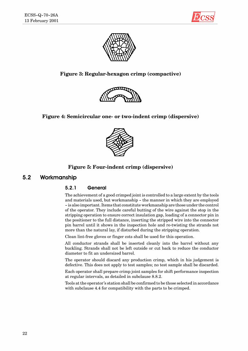
Figure 3: Regular-hexagon crimp (compactive)
Figure 4: Semicircular one- or two-indent crimp (dispersive)
Figure 5: Four-indent crimp (dispersive)
5.2 Workmanship
5.2.1 GeneralThe achievement of a good crimped joint is controlled to a large extent by the toolsand materials used, but workmanship -- the manner in which they are employed-- is also important. Items that constituteworkmanship are thoseunder the controlof the operator. They include careful butting of the wire against the stop in thestripping operation to ensure correct insulation gap, loading of a connector pin inthe positioner to the full distance, inserting the stripped wire into the connectorpin barrel until it shows in the inspection hole and re-twisting the strands notmore than the natural lay, if disturbed during the stripping operation.
Clean lint-free gloves or finger cots shall be used for this operation.
All conductor strands shall be inserted cleanly into the barrel without anybuckling. Strands shall not be left outside or cut back to reduce the conductordiameter to fit an undersized barrel.
The operator should discard any production crimp, which in his judgement isdefective. This does not apply to test samples; no test sample shall be discarded.
Each operator shall prepare crimp joint samples for shift performance inspectionat regular intervals, as detailed in subclause 8.8.2.
Tools at the operator’s station shall be confirmed to be those selected in accordancewith subclause 4.4 for compatibility with the parts to be crimped.

ECSS 13 February 2001
ECSS--Q--70--26A
23
5.2.2 Connector barrel and single wire crimpinga. Tools specified in MIL--DTL--22520 shall be used.
b. Preference shall be given to the selection of single wire interconnections.
c. Strands of wire shall not be doubled back to increase the conductor diameter.
d. In special cases additional stranded wires may be used to increase the cross-sectional area up to a selected barrel size, provided that the insulation is pre-pared as normal and transparent “shrink-fit insulation” is used to cover theloose end of thewire to prevent any risk of a short circuit (see subclause 5.2.3).
e. For 22 AWGup to 16 AWGwire sizes, themaximuminsulation clearance shallbe equal to the outside diameter (over the insulation) of the wire being used.The gaps for larger sizewires shall not exceed2mm.Nominimumgap is speci-fied except that the conductorwire shall be visible topermit inspection.Wherethe terminal or contact is supplied with insulation support, the wire insula-tion shall enter the support to the extent that no bare wire is exposed.
Examples of crimping parameters are given in Table 1 (as a guideline) and anexample of a typical connector barrel and single wire crimping is shown inFigure 6.
Figure 6: Example of a typical connector barrel and single wire crimping

ECSS13 February 2001ECSS--Q--70--26A
24
Table 1: Guideline for selector setting —Four-indent crimp (dispersive)
Single wire — Crimping tool 22520/2--01Connector Wire gauge
(AWG)Wire barrelcontact size
Selector setting
18 20 -- 18 5
20 20 -- 18 5
S20 20 -- 20 7
SU 22 20 -- 20 6UB*
24 20 -- 20 5*D
26 20 -- 26 6D
28 20 -- 26 6
22 22 -- 22 4
24 22 -- 22 3
12 12 -- 12 8 G
16 16 -- 16 7 G
18 16 -- 16 6 G
3 20 16 -- 16 5 G89
20 20 -- 20 799 22 20 -- 20 699 24 20 -- 20 5
22 22 -- 22 5
24 22 -- 22 4
26 22 -- 22 3
12 12 -- 12 8 G
20 12 -- 16 6 G
16 16 -- 16 6 G
D18 16 -- 16 5 G
DB 20 16 -- 16 4 GBAS
20 20 -- 20 6S 22 20 -- 20 6
24 20 -- 20 5
26 20 -- 26 5
28 20 -- 26 5
HE
22 22 -- 22 5E80
24 22 -- 22 401 26 22 -- 22 4
NOTE: G = Setting of crimping tool 22520/1-01
ECSS 13 February 2001
ECSS--Q--70--26A
25
5.2.3 Connector barrel and multiple wire crimpingAlthoughnot generally recommended, crimpingmultiplewires into a single crimpbarrel may be used as long as the following requirements are met.
a. Tools specified in MIL--DTL--22520 shall be used.
b. The maximum number of wires in one crimp barrel is limited to two.
c. The sum of the two nominal conductor sections is compatible with the crimpbarrel used (i.e. 2 × 24 AWG approximately equal to 1 × 20 AWG).
d. Both conductors shall be of the same material and support the same platingfinish (i.e. both silver and not a combination of silver and nickel).
e. Before introduction into the barrel, where possible, wires or conductors maybe twisted to obtain a “single” conductor.
f. Axial strengthmeasurements shall be performed on the two associated wiresand the axial strength shall be as aminimum75 %of the sum of the twowiresaxial strength requirements.
g. Where appropriate, wires may be introduced into the barrel as separate con-ductors. When this method is used the actual strengthmeasurement shall beperformed on one of the wires (the smaller, if two different sizes are used) andthe axial strength requirement shall be as quoted in Table 5 for the actual sizeof wire pulled, assuming a barrel size equal to that wire’s gauge.
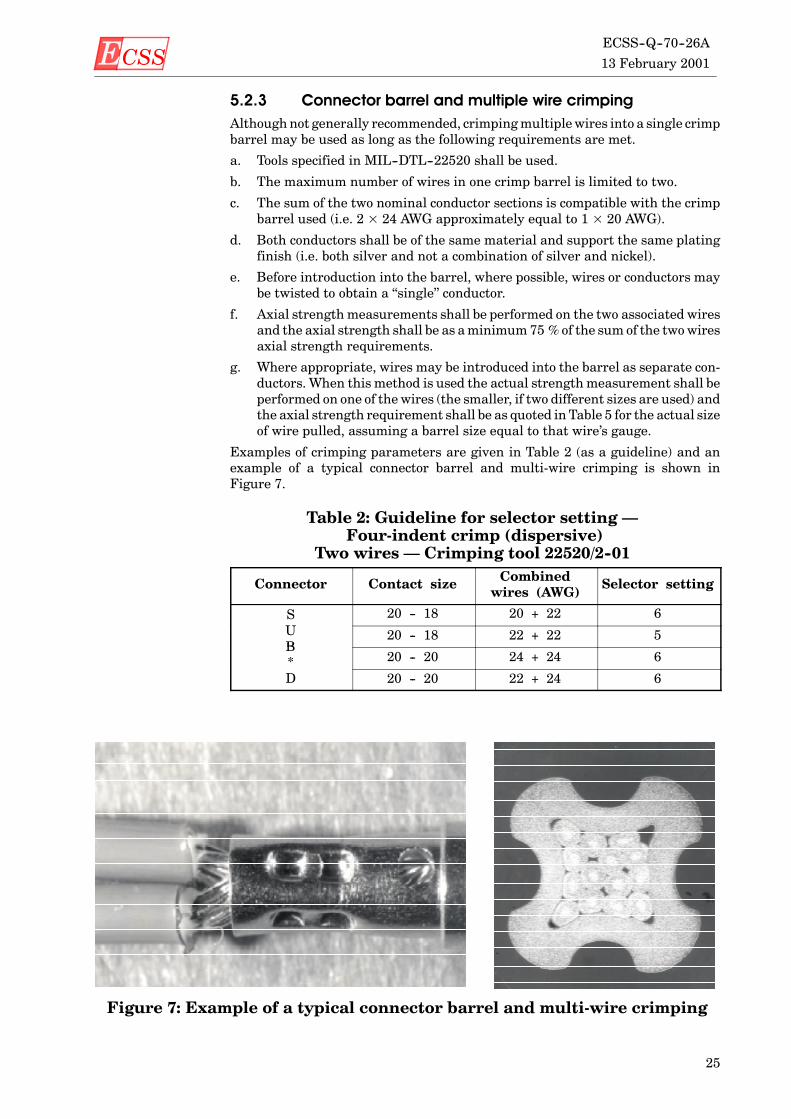
Examples of crimping parameters are given in Table 2 (as a guideline) and anexample of a typical connector barrel and multi-wire crimping is shown inFigure 7.
Table 2: Guideline for selector setting —Four-indent crimp (dispersive)
Two wires — Crimping tool 22520/2--01
Connector Contact size Combinedwires (AWG)
Selector setting
SU
20 -- 18 20 + 22 6UB
20 -- 18 22 + 22 5B* 20 -- 20 24 + 24 6
D 20 -- 20 22 + 24 6
Figure 7: Example of a typical connector barrel and multi-wire crimping

ECSS13 February 2001ECSS--Q--70--26A
26
5.2.4 Ferrule shield crimpinga. Tools specified in MIL--DTL--22520 shall be used.
b. The shielded wires on coaxial cables shall be braided.
c. Axial strength measurements shall be performed only on the shield afterremoval of the core dielectric.
d. Following crimping the assembly shall be protected by shrink tubing.
Examples of crimping parameters are given in Table 3 (as a guideline) and anexample of a typical ferrule shield crimping is shown in Figure 8.
Table 3: Guideline for die selection(ferrule coaxial shield crimping)
Coaxialconnectorferrule
Coaxial cable 22520/5--01 tooldie selection
22520/10--01tool dieselection
SU
RG 178 BU 22520/5--03 B 22520/10--05 BUB*
50 CIS 22520/5--03 A 22520/10--05 A*D RG 180 BU DANIELS Y 322 A --
SMA
50 CIS 22520/5--03 A 22520/10--05 A
Figure 8: Example of a typical ferrule shield crimping
ECSS 13 February 2001
ECSS--Q--70--26A
27
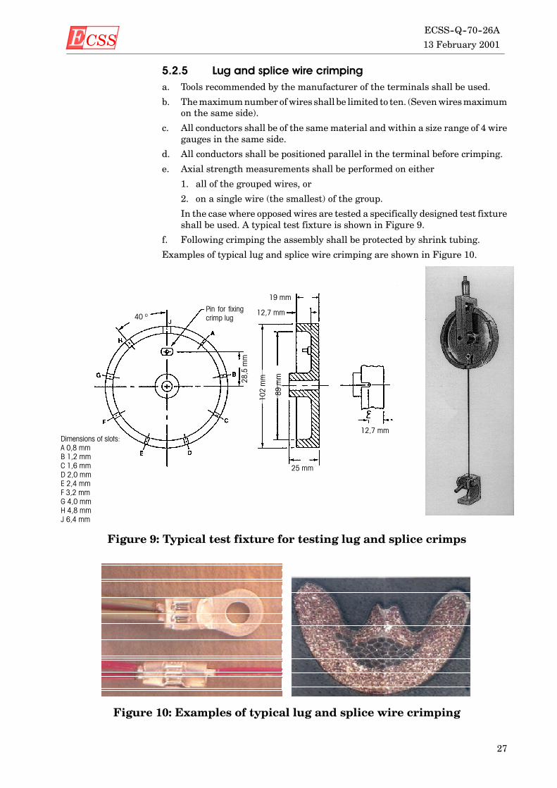
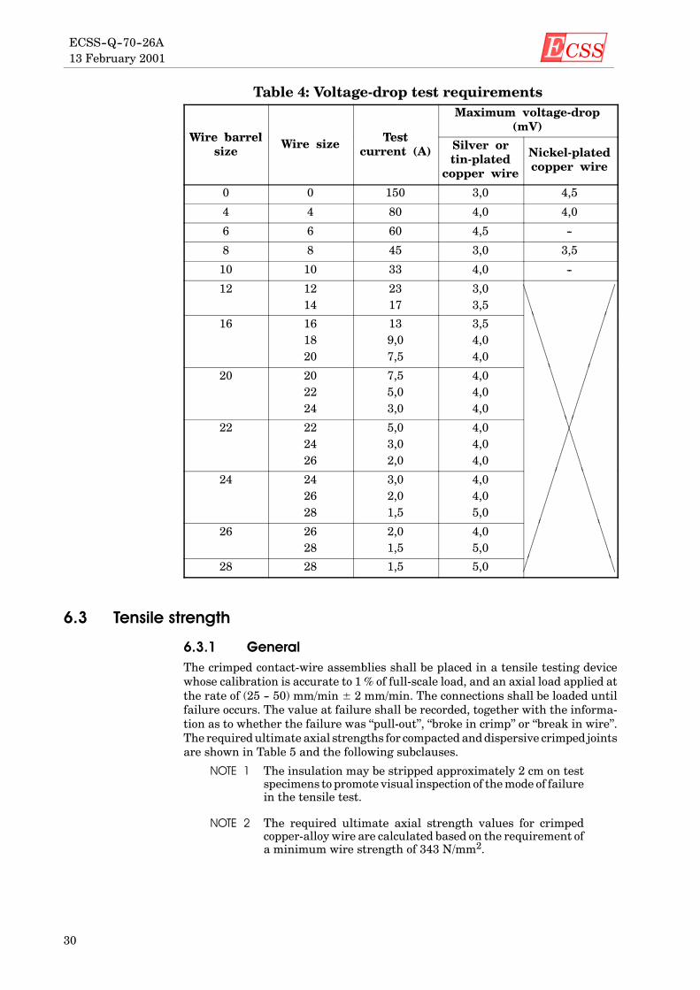
5.2.5 Lug and splice wire crimpinga. Tools recommended by the manufacturer of the terminals shall be used.
b. Themaximumnumber ofwires shall be limited to ten. (Sevenwiresmaximumon the same side).
c. All conductors shall be of the same material and within a size range of 4 wiregauges in the same side.
d. All conductors shall be positioned parallel in the terminal before crimping.
e. Axial strength measurements shall be performed on either
1. all of the grouped wires, or
2. on a single wire (the smallest) of the group.
In the case where opposed wires are tested a specifically designed test fixtureshall be used. A typical test fixture is shown in Figure 9.
f. Following crimping the assembly shall be protected by shrink tubing.
Examples of typical lug and splice wire crimping are shown in Figure 10.
Dimensions of slots:A 0,8 mmB 1,2 mmC 1,6 mmD 2,0 mmE 2,4 mmF 3,2 mmG 4,0 mmH 4,8 mmJ 6,4 mm
19 mm
12,7 mm
89mm
102mm28,5mm
25 mm
12,7 mm
Pin for fixingcrimp lug40 º
Figure 9: Typical test fixture for testing lug and splice crimps
Figure 10: Examples of typical lug and splice wire crimping

ECSS13 February 2001ECSS--Q--70--26A
28
5.3 Workmanship standardsThe supplier shall prepare and have readily available visual standards consistingof satisfactory work samples or visual aids which clearly illustrate the qualitycharacteristics of all crimped connections utilized. Defects such as those listed insubclause 7.1.1 and shown in Figure 11 shall be included as examples.
Acceptable Not acceptable
wire visible
Insulation clearance < 2 mm(when wire > 16 AWG)
D
damaged crimpbarrel
wire not visible
wire strandoutside crimp
damagedinsulation
Insulation clearance> D(when wire is 28 AWGup to 16 AWG)
Unacceptable – undercrimpD Voids greater than 10 %D Wire not deformed
AcceptableD All wire strands deformedD Voiding less than 10 %
Preferred
Figure 11: Workmanship examples and crimp microsections

ECSS 13 February 2001
ECSS--Q--70--26A
29
6
Test method
6.1 GeneralSamples shall be submitted to all or some of the tests detailed below. The numberof samples is dependent on the specific process requirement (see subclauses 8.4.2,8.5 and 8.8.2). Records of all results shall be tabulated in accordance with sub-clause 8.2. Prior to testing, the inspector shall also inspect the samples and applyto these the inspection criteria detailed in subclause 7.1.1.
6.2 Voltage-dropThe voltage-drop shall bemeasured fromapoint on the positioning shoulder of thecontact to another point 14mmdistant on the attachedwire (see Figure 12). In thecase of two ormore wires being crimped in the same contact, lug or splice, the volt-age-drop measurement shall be performed on each wire. The voltage-drop of thecontact crimp joint shall not exceed the value specified in Table 4 for each wiretested.
14 mm
Figure 12: Measurement of voltage-drop across a crimped termination
ECSS13 February 2001ECSS--Q--70--26A
30
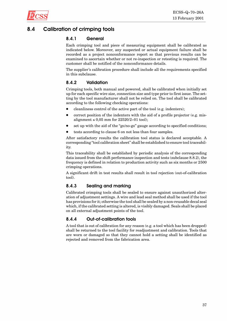
Table 4: Voltage-drop test requirements
Wire barrel Test
Maximum voltage-drop(mV)
Wire barrelsize
Wire size Testcurrent (A) Silver or
tin-platedcopper wire
Nickel-platedcopper wire
0 0 150 3,0 4,5
4 4 80 4,0 4,0
6 6 60 4,5 --
8 8 45 3,0 3,5
10 10 33 4,0 --
12 1214
2317
3,03,5
16 161820
139,07,5
3,54,04,0
20 202224
7,55,03,0
4,04,04,0
22 222426
5,03,02,0
4,04,04,0
24 242628
3,02,01,5
4,04,05,0
26 2628
2,01,5
4,05,0
28 28 1,5 5,0
6.3 Tensile strength
6.3.1 GeneralThe crimped contact-wire assemblies shall be placed in a tensile testing devicewhose calibration is accurate to 1 % of full-scale load, and an axial load applied atthe rate of (25 -- 50) mm/min ± 2 mm/min. The connections shall be loaded untilfailure occurs. The value at failure shall be recorded, together with the informa-tion as to whether the failure was “pull-out”, “broke in crimp” or “break in wire”.The required ultimate axial strengths for compacted anddispersive crimped jointsare shown in Table 5 and the following subclauses.
NOTE 1 The insulation may be stripped approximately 2 cm on testspecimens to promote visual inspection of themode of failurein the tensile test.
NOTE 2 The required ultimate axial strength values for crimpedcopper-alloy wire are calculated based on the requirement ofa minimum wire strength of 343 N/mm2.

ECSS 13 February 2001
ECSS--Q--70--26A
31
6.3.2 Connector barrel wire crimpinga. The required axial strength shall be as a minimum 75 % of the wire strength.
b. Table 5 details the minimum requirements for axial strength for copper andcopper-alloy wires having either silver-, tin- or nickel-plated finishes.
Table 5: Required ultimate axial strength for compactiveand dispersive crimped joints
Axial strength (Newton)
Wirebarrel
Wire size(AWG)
Silver- ortin-plated
copper wire
Nickel-plated
copper wire
Copper-alloywire
0 02
31202450
28002200
--
2 24
24501780
22001600
--
4 46
17801330
16001200
--
6 68
1330980
1200890
--
8 8 1250 1150 --
10 1012
710500
----
--
12 1214
500320
----
----
16 161820
23015590
------
------
20 202224
906040
------
18511560
22 222426
6040--
------
1156045
24 242628
40----
------
604530
26 2628
----
----
4530
28 28 -- -- 30NOTE 1 Wire barrel size < 6 AWG tools are without adjustable setting.
NOTE 2 Wire barrel sizes " 8 AWG tools are generally with adjustable settings which permit optimized crimpedjoints having higher axial strengths.

ECSS13 February 2001ECSS--Q--70--26A
32
6.3.3 Ferrule, lug and splice crimpingThe required axial strength shall be as a minimum
D 70 % of the shield strength,
D 70%of one of the smallest gaugewireswithin the connection if pulled individ-ually, or
D 70 % of the sum of all the wires axial strength requirements if all wires arepulled together.
6.4 MetallographyThe joint to be sectioned shall bemounted in a low exotherm resin capable of beingmoulded without the application of external pressure. The joint shall be sooriented that the wire is perpendicular to the polishing surface. The specimenshall be ground with the aid of the appropriate grades of silicon carbide papers toexpose the mid-section of the joint. This section shall then be polished with suc-cessively finer grades of diamond paste down to 1 µm. To aid microscopic examin-ation, the polished section shall later be very lightly etched with an appropriatechemical reagent specific to the composition of the materials being crimped.

ECSS 13 February 2001
ECSS--Q--70--26A
33
7
Acceptance criteria
7.1 Validation and qualification testing
7.1.1 Visual inspectionDuring visual inspection the following acceptance criteria shall be met; failure tomeet the acceptance criteria shall be cause for rejection.
a. Insulation is not damaged by the crimping tool or the terminal.
b. The conductor is visible in the inspection hole when an inspection hole isprovided.
c. The crimp barrel has no unintentional sharp edges, peeled metal, burrs,cracked platings or cuts after crimping. All functional parts, including allretention clips or locking devices, are operational after the crimp has beenmade.
d. No tarnished or corroded contacts are present.
e. Nomisplaced crimps, as determined bymarks found on areas not designed totake crimping, are present.
f. Noundercrimpsor overcrimps (e.g. an undercrimpdetected bya loose conduc-tor or an overcrimp detected because of broken strands or deformed wire atend of terminal) are present. If detected this shall be cause to stop operationsat that station, to reject all production crimpsmade since the last verificationor pull test and to investigate tool, wire and terminals for the cause of failure.
g. No bent contacts are present.
7.1.2 Voltage-drop testThe acceptance criteria for the voltage-drop test are given in Table 4.
7.1.3 Tensile strength testThe measured values for ultimate axial strength shall conform to those listed inTable 5 and subclauses 6.3.2 and 6.3.3.
7.1.4 MetallographyThe section shall be examined in both as-polished and etched states using ametal-lographic microscope at a suitable magnification up to ×400.
a. Each microsection shall be free from contamination.

ECSS13 February 2001ECSS--Q--70--26A
34
b. The crimp barrel shall be evenly deformed.
c. Voids shall occupy less than 10 % of the cross-sectioned area of the wire vol-ume.
d. Thewiresandbarrel should appear as agas-tight joint or conformto thework-manship sample prepared during qualification or validation of the specificcrimp connection.
e. All wires shall be deformed from their circular cross-section.
f. There shall be no indentations or fracturing of the deformed receptacle barrelor its plated finish.
NOTE 1 For ferrule shield crimping the requirements of c. and e. arenot applicable.
NOTE 2 For wire barrel contact size 20 -- 18 the requirement c. is notapplicable due to localized voiding at the crimp corners.
7.2 Shift performance testSamples shall be submitted to visual inspection and tensile tests (as detailed insubclause 8.8.2). If any sample fails to meet the acceptance criteria all productioncrimps produced by the crimp tool concerned subsequent to its last shift perform-ance sampling shall be rejected.

ECSS 13 February 2001
ECSS--Q--70--26A
35
8
Quality assurance
8.1 GeneralThe quality assurance requirements are defined in ECSS--Q--20. Particularattention shall be given to the following points (see also Figure 13).
8.2 DataThe quality records (e.g. logbooks) shall be retained for at least ten years or inaccordance with project contract requirements, and contain as a minimum thefollowing.
D the as-built and test configuration list (waiver and deviation summary);
D nonconformance reports and corrective actions;
D copy of the visual inspection and shift performance test results with referenceto the relevant procedure, personnel and tools used;
D records of the training, testing and certification status of crimping operators(see subclause 8.7) and ECSS--Q--70--08A, subclause 14.8.
8.3 NonconformanceAny nonconformance which is observed in respect of the process shall be disposi-tioned in accordance with the quality assurance requirements, seeECSS--Q--20--09. Furthermore, failure of a crimping tool to pass any requirementspecified in subclause 4.4.1 shall require rejection of all crimps made by that toolsince it was last tested successfully for acceptance.

ECSS13 February 2001ECSS--Q--70--26A
36
Personnel training and certification(see subclause 8.7)
Initial calibration of new crimpingtools using go/no-go gauges and
sample crimps(see subclause 8.4.2)
Compatibility of parts, crimping andstripping tools
(see subclauses 4.4 and 5.2)
Insulation stripping(see subclause 4.4.2)
Pre-crimp inspection of wire byquality assurance
(see subclause 8.8.1 a.)
Remove stripping tool fromthe area and
repair/recalibrate or rejectas necessary
Performance inspection and test atbeginning of shift or a series of
crimping operations(see subclause 8.8.2)
All production crimpsperformed with the crimptool concerned since itslast acceptable sampling
shall be rejected
Crimping operation
REJECTPost-crimp inspection by quality
assurance(see subclause 8.8.1 b.)
ACCEPT
nonconformance
nonconformance
nonconformance
nonconformance
Definition of tool setting parameters(see subclause 8.5)
Unable to calibrateREJECT
Figure 13: Guide to quality controls during crimping operation
ECSS 13 February 2001
ECSS--Q--70--26A
37
8.4 Calibration of crimping tools
8.4.1 GeneralEach crimping tool and piece of measuring equipment shall be calibrated asindicated below. Moreover, any suspected or actual equipment failure shall berecorded as a project nonconformance report so that previous results can beexamined to ascertain whether or not re-inspection or retesting is required. Thecustomer shall be notified of the nonconformance details.
The supplier’s calibration procedure shall include all the requirements specifiedin this subclause.
8.4.2 ValidationCrimping tools, both manual and powered, shall be calibrated when initially setup for each specific wire size, connection size and type prior to first issue. The set-ting by the tool manufacturer shall not be relied on. The tool shall be calibratedaccording to the following checking operations:
D cleanliness control of the active part of the tool (e.g. indenters);
D correct position of the indenters with the aid of a profile projector (e.g. mis-alignment #$0,05 mm for 22520/2--01 tool);
D set up with the aid of the “go/no-go” gauge according to specified conditions;
D tests according to clause 6 on not less than four samples.
After satisfactory results the calibration tool status is declared acceptable. Acorresponding “tool calibration sheet” shall be established to ensure tool traceabil-ity.
This traceability shall be established by periodic analysis of the correspondingdata issued from the shift performance inspection and tests (subclause 8.8.2), thefrequency is defined in relation to production activity such as six months or 2500crimping operations.
A significant drift in test results shall result in tool rejection (out-of-calibrationtool).
8.4.3 Sealing and markingCalibrated crimping tools shall be sealed to ensure against unauthorized alter-ation of adjustment settings. A wire and lead seal method shall be used if the toolhas provisions for it; otherwise the tool shall be sealed by anon-reusable decal sealwhich, if the calibrated setting is altered, is visibly damaged. Seals shall be placedon all external adjustment points of the tool.
8.4.4 Out-of-calibration toolsA tool that is out of calibration for any reason (e.g. a tool which has been dropped)shall be returned to the tool facility for readjustment and calibration. Tools thatare worn or damaged so that they cannot hold a setting shall be identified asrejected and removed from the fabrication area.

ECSS13 February 2001ECSS--Q--70--26A
38
8.5 Requirements for new crimp configurations
8.5.1 GeneralCrimp configurations or designs that are not contained in this Standard shall besubjected to the following tests in order to determine the optimum operation para-meters.
8.5.2 Test procedurea. The settings recommended by the crimping tool manufacturer may be used
as a starting point for calibrating tools. Ten samples shall be prepared at thispoint and pulled; the tool indenter opening shall then be varied in convenientincrements above and below this point, and ten samples pulled at each in-crement. The minimum in voltage-drop and maximum in tensile strengthshall be determined and evaluated as per Figure 14. The design value or oper-ating point should lie approximately in themiddle of the flat top portion of thetensile-strength plot (see Figure 14 for an example).
b. When a previously undocumented contact and wire combination is proposedfor use, a plot as delineated above shall be made, increments being closeenough together to obtain a smooth curve. From this plot, an optimum settingcan be chosen approximately in themiddle of the flat top portion of the tensile-strength curve. This point is the operating point for the toolswith that specificcombination of contact and wire and shall be entered in the process records.
c. Voltage drop tests shall be performed on five samples corresponding to theoperating point.
d. Metallography tests shall be performed on a minimum of three of thesesamples corresponding to the operating point.
e. The remaining samples shall be retained for reference.
f. This approach is conducted fromthe variation of themain parameter involvedto the relevant terminal crimping.
S Connector barrel crimping: selector setting;
S Ferrule crimping: die selection;
S Lug and splice crimping: total cross-section of stranded wires.
8.5.3 Sealing and markingSee subclause 8.4.3.

ECSS 13 February 2001
ECSS--Q--70--26A
39
Decreasingcross-sectionalarea
Increasing
jointconductivity
Increasing
tensilestrength
Increasing indentation depth
Figure 14: Typical plots showing variation in crimp terminationcharacteristics with increasing indentation depth
8.6 TraceabilityTraceability shall bemaintained throughout the process from incoming inspectionto final test, including details of test equipment, tools and personnel employed inperforming the task.
8.7 Personnel trainingTrained and competent personnel shall be employed for all crimping operations.A training programme shall be developed, maintained and implemented toprovide for excellence of workmanship and personnel skills, careful and safeoperations, and improvement of the quality of crimped joints.
Trained personnel, performing crimping operations, shall be certified. Thecertification of personnel shall be based upon objective evidence of crimp quality,resulting from test and inspection of the crimped joints. Re-certification ofpersonnel shall apply in cases of repeatedly unacceptable quality levels andchanges in crimping techniques, parameters or required skills.
Records shall be maintained of the training and certification status of crimpingoperators and inspection personnel.
All training and certification shall only be performed at a school authorized by thefinal customer.
ECSS13 February 2001ECSS--Q--70--26A
40
8.8 Inspections
8.8.1 Visual inspection (performed by operator)a. Pre-crimp inspection
Before the stripped wire is inserted into the contact or terminal barrel, thewire shall be examined for nicks, rings, broken strands, untwisted lay orunremoved insulation in the area of the crimp.Damagedwireswhere the basematerial is exposed shall not beused.Contacts and terminal barrels that showevidence of the presence of tarnish, corrosion or physical damage, includingbent contacts, shall not be used.
Inspection shall verify that wire size and type and the contact or terminal areas specified in the drawing or control document.
b. Post-crimp inspection
The inspection shall be carried out with the aid of a binocularmicroscope hav-ing an initial linear magnification no greater than ×7. Further examinationof surface characteristics can be performed at higher magnifications. Partsand conductor leads shall not be physically disturbed to aid inspection. Theacceptance criteria are described in subclause 7.1.
8.8.2 Shift performance inspection and testAt the beginning of a shift or before a series of crimping operations, each operatorshall prepare four samples. At the end of the operation four further samples shallbe crimped.
Alternatively, a logbook shall be kept for each tool. The logbook shall show thequantity of parts crimped since each calibration and since each go/no-go operation.Four samples shall be crimped after each 100 crimping operations have been per-formed.
A tool shall be changed whenever a wire size or contact size is changed. The oper-ator shall prepare four samples at the start of the operation after such a change.
Thismay be omitted if samples have already been prepared by the tool during theshift.
In each case three samples shall be submitted to the tensile strength test detailedin subclause 6.3. The test requirements are given in subclause 7.1.3.
The fourth sample shall be retained for reference and traceability purposes (sub-clause 8.4.2).
Analysis of shift performance test results, in comparison with initial tool calibra-tion results, shall be used to determine any drift in tool performance.

ECSS 13 February 2001
ECSS--Q--70--26A
41
ECSS Document Improvement Proposal1. Document I.D.ECSS--Q--70--26A
2. Document date13 February 2001
3. Document titleCrimping of high-reliabilityelectrical connections
4. Recommended improvement (identify clauses, subclauses and include modified text orgraphic, attach pages as necessary)
5. Reason for recommendation
6. Originator of recommendation
Name: Organization:
Address: Phone:Fax:e-mail:
7. Date of submission:
8. Send to ECSS Secretariat
Name:W. KriedteESA--TOS/QR
Address:ESTEC, P.O. Box 2992200 AG NoordwijkThe Netherlands
Phone: +31--71--565--3952Fax: +31--71--565--6839e-mail: [email protected]
Note: The originator of the submission should complete items 4, 5, 6 and 7.This form is available as a Word and Wordperfect--Template on internet under
http://www.estec.esa.nl/ecss/improve/

ECSS13 February 2001ECSS--Q--70--26A
42
(This page is intentionally left blank)