space product assurance - esmat.esa.intesmat.esa.int/ecss-q-70-18a.pdf · for space standardization...
TRANSCRIPT

FOR SPACE STANDARDIZATION
EUROPEAN COOPERATION
ECSS
Space productassurance
Preparation, assembly and mountingof RF coaxial cables
ECSS SecretariatESA-ESTEC
Requirements & Standards DivisionNoordwijk, The Netherlands
ECSS-Q-70-18A31 August 2001

ECSS31 August 2001ECSS--Q--70--18A
2
Published by: ESA Publications DivisionESTEC, P.O. Box 299,2200 AG Noordwijk,The Netherlands
ISSN: 1028-396X
Price: � 10
Printed in The Netherlands
Copyright 2001 E by the European Space Agency for the members of ECSS

ECSS 31 August 2001
ECSS--Q--70--18A
3
Foreword
This Standard is one of the series of ECSS Standards intended to be appliedtogether for the management, engineering and product assurance in spaceprojects and applications. ECSS is a cooperative effort of the European SpaceAgency, national space agencies and European industry associations for thepurpose of developing and maintaining common standards.
Requirements in thisStandardare defined in termsofwhat shall be accomplished,rather than in terms of how to organize and perform the necessary work. Thisallows existing organizational structures and methods to be applied where theyare effective, and for the structures and methods to evolve as necessary withoutrewriting the standards.
The formulation of this Standard takes into account the existing ISO 9000 familyof standards.
This Standard has been prepared by editing ESA PSS--01--718, reviewed by theECSS Technical Panel and approved by the ECSS Steering Board.

ECSS31 August 2001ECSS--Q--70--18A
4
(This page is intentionally left blank)

ECSS 31 August 2001
ECSS--Q--70--18A
5
Contents
Foreword 3. . . . . . . . . . . . . . . . . . . . . . . . . . . . . . . . . . . . . . . . . . . . . . . . . . . . . . . . .
Introduction 9. . . . . . . . . . . . . . . . . . . . . . . . . . . . . . . . . . . . . . . . . . . . . . . . . . . . . .
1 Scope 11. . . . . . . . . . . . . . . . . . . . . . . . . . . . . . . . . . . . . . . . . . . . . . . . . . . . . . . .
2 Normative references 13. . . . . . . . . . . . . . . . . . . . . . . . . . . . . . . . . . . . . . . . .
3 Terms, definitions and abbreviated terms 15. . . . . . . . . . . . . . . . . . . . . . .
3.1 Terms and definitions 15. . . . . . . . . . . . . . . . . . . . . . . . . . . . . . . . . . . . . . . . . . . . . . .
3.2 Abbreviated terms 15. . . . . . . . . . . . . . . . . . . . . . . . . . . . . . . . . . . . . . . . . . . . . . . . .
4 Principles and prerequisites of reliable soldered or crimped cable
connections 17. . . . . . . . . . . . . . . . . . . . . . . . . . . . . . . . . . . . . . . . . . . . . . . . . .
4.1 Principles of reliable soldered or crimped semi-rigid cable connections 17. .
4.2 Prerequisites for assembly and mounting of semi-rigid coaxial cables 17. . . .
4.3 Alternative coaxial cable technologies 18. . . . . . . . . . . . . . . . . . . . . . . . . . . . . . .
5 Preparatory conditions 19. . . . . . . . . . . . . . . . . . . . . . . . . . . . . . . . . . . . . . . .
5.1 Facility cleanliness 19. . . . . . . . . . . . . . . . . . . . . . . . . . . . . . . . . . . . . . . . . . . . . . . . .

ECSS31 August 2001ECSS--Q--70--18A
6
5.2 Environmental conditions 19. . . . . . . . . . . . . . . . . . . . . . . . . . . . . . . . . . . . . . . . . . .
5.3 Lighting requirements 19. . . . . . . . . . . . . . . . . . . . . . . . . . . . . . . . . . . . . . . . . . . . . .
5.4 Equipment and tools 20. . . . . . . . . . . . . . . . . . . . . . . . . . . . . . . . . . . . . . . . . . . . . . .
6 Material selection 23. . . . . . . . . . . . . . . . . . . . . . . . . . . . . . . . . . . . . . . . . . . . .
6.1 Solder 23. . . . . . . . . . . . . . . . . . . . . . . . . . . . . . . . . . . . . . . . . . . . . . . . . . . . . . . . . . . .
6.2 Flux 23. . . . . . . . . . . . . . . . . . . . . . . . . . . . . . . . . . . . . . . . . . . . . . . . . . . . . . . . . . . . . .
6.3 Solvents 23. . . . . . . . . . . . . . . . . . . . . . . . . . . . . . . . . . . . . . . . . . . . . . . . . . . . . . . . . .
6.4 Cable selection 24. . . . . . . . . . . . . . . . . . . . . . . . . . . . . . . . . . . . . . . . . . . . . . . . . . .
6.5 Connector selection 24. . . . . . . . . . . . . . . . . . . . . . . . . . . . . . . . . . . . . . . . . . . . . . .
7 Preparation of semi-rigid cable 27. . . . . . . . . . . . . . . . . . . . . . . . . . . . . . . .
7.1 General 27. . . . . . . . . . . . . . . . . . . . . . . . . . . . . . . . . . . . . . . . . . . . . . . . . . . . . . . . . .
7.2 Inspection of cable 27. . . . . . . . . . . . . . . . . . . . . . . . . . . . . . . . . . . . . . . . . . . . . . . .
7.3 Cutting cable to initial oversize length 27. . . . . . . . . . . . . . . . . . . . . . . . . . . . . . . .
7.4 Cable forming and minimum bend radius 27. . . . . . . . . . . . . . . . . . . . . . . . . . . .
7.5 Preconditioning heat treatment 28. . . . . . . . . . . . . . . . . . . . . . . . . . . . . . . . . . . . . .
7.6 Trimming cable to final length 29. . . . . . . . . . . . . . . . . . . . . . . . . . . . . . . . . . . . . . .
7.7 Stripping the cable ends 29. . . . . . . . . . . . . . . . . . . . . . . . . . . . . . . . . . . . . . . . . . . .
7.8 Inspection of stripped cable ends 30. . . . . . . . . . . . . . . . . . . . . . . . . . . . . . . . . . .
8 Preparation for soldering assembly of semi-rigid cables 31. . . . . . . . .
8.1 General 31. . . . . . . . . . . . . . . . . . . . . . . . . . . . . . . . . . . . . . . . . . . . . . . . . . . . . . . . . .
8.2 Degolding and pretinning 31. . . . . . . . . . . . . . . . . . . . . . . . . . . . . . . . . . . . . . . . . .
8.3 Solder preforms 32. . . . . . . . . . . . . . . . . . . . . . . . . . . . . . . . . . . . . . . . . . . . . . . . . . .
9 Assembly of connectors to RF coaxial cables 33. . . . . . . . . . . . . . . . . . .
9.1 Solder assembly of semi-rigid cables 33. . . . . . . . . . . . . . . . . . . . . . . . . . . . . . . . .
9.2 Crimp assembly of semi-rigid cables and other assembly techniques 37. . . .
9.3 Completed assemblies 37. . . . . . . . . . . . . . . . . . . . . . . . . . . . . . . . . . . . . . . . . . . . .
10 Mounting of cables 39. . . . . . . . . . . . . . . . . . . . . . . . . . . . . . . . . . . . . . . . . . .
10.1 Semi-rigid cables with straight solder-type connectors 39. . . . . . . . . . . . . . . . . .
10.2 Semi-rigid cables with right-angle connectors 40. . . . . . . . . . . . . . . . . . . . . . . . .
10.3 Other cable mounting technologies 40. . . . . . . . . . . . . . . . . . . . . . . . . . . . . . . . .

ECSS 31 August 2001
ECSS--Q--70--18A
7
11 Process verification 41. . . . . . . . . . . . . . . . . . . . . . . . . . . . . . . . . . . . . . . . . . . .
11.1 General 41. . . . . . . . . . . . . . . . . . . . . . . . . . . . . . . . . . . . . . . . . . . . . . . . . . . . . . . . . .
11.2 Temperature cycling 41. . . . . . . . . . . . . . . . . . . . . . . . . . . . . . . . . . . . . . . . . . . . . . .
11.3 Vibration 41. . . . . . . . . . . . . . . . . . . . . . . . . . . . . . . . . . . . . . . . . . . . . . . . . . . . . . . . . .
12 Quality assurance 43. . . . . . . . . . . . . . . . . . . . . . . . . . . . . . . . . . . . . . . . . . . . .
12.1 General 43. . . . . . . . . . . . . . . . . . . . . . . . . . . . . . . . . . . . . . . . . . . . . . . . . . . . . . . . . .
12.2 Data 43. . . . . . . . . . . . . . . . . . . . . . . . . . . . . . . . . . . . . . . . . . . . . . . . . . . . . . . . . . . . .
12.3 Nonconformance 43. . . . . . . . . . . . . . . . . . . . . . . . . . . . . . . . . . . . . . . . . . . . . . . . .
12.4 Calibration 43. . . . . . . . . . . . . . . . . . . . . . . . . . . . . . . . . . . . . . . . . . . . . . . . . . . . . . .
12.5 Traceability 43. . . . . . . . . . . . . . . . . . . . . . . . . . . . . . . . . . . . . . . . . . . . . . . . . . . . . . .
12.6 Workmanship standards 43. . . . . . . . . . . . . . . . . . . . . . . . . . . . . . . . . . . . . . . . . . . .
12.7 Inspection 44. . . . . . . . . . . . . . . . . . . . . . . . . . . . . . . . . . . . . . . . . . . . . . . . . . . . . . . .
12.8 Operator and inspector training and certification 44. . . . . . . . . . . . . . . . . . . . . .
Annex A (informative) Workmanship standards 45. . . . . . . . . . . . . . . . . . . . . . .
Figures
Figure 1: Typical cable cut-off fixture 20. . . . . . . . . . . . . . . . . . . . . . . . . . . . . . . . . . . . . . . . . . . . .
Figure 2: Typical cable-forming tool 21. . . . . . . . . . . . . . . . . . . . . . . . . . . . . . . . . . . . . . . . . . . . . .
Figure 3: Approved and non-approved straight solder-type cable-end connectors 25. . . . .
Figure 4: Typical dimensional inspection requirements 30. . . . . . . . . . . . . . . . . . . . . . . . . . . . . .
Figure 5: Method of producing solder preforms 32. . . . . . . . . . . . . . . . . . . . . . . . . . . . . . . . . . . .
Figure 6: Centre contact assembly 33. . . . . . . . . . . . . . . . . . . . . . . . . . . . . . . . . . . . . . . . . . . . . .
Figure 7: Right angle cable-end connector assembly 36. . . . . . . . . . . . . . . . . . . . . . . . . . . . . .
Figure A-1: Photograph showing non-captive nut and preferred solder fillet 45. . . . . . . . . . .
Figure A-2: Microsection through preferred solder fillet, revealing full penetrationof solder path 45. . . . . . . . . . . . . . . . . . . . . . . . . . . . . . . . . . . . . . . . . . . . . . . . . . . . . . .
Figure A-3: Unacceptable solder fillet dimensions 45. . . . . . . . . . . . . . . . . . . . . . . . . . . . . . . . . .
Tables
Table 1: Design rules for minimum bend radius 28. . . . . . . . . . . . . . . . . . . . . . . . . . . . . . . . . . . .
Table 2: Preconditioning heat treatment process 29. . . . . . . . . . . . . . . . . . . . . . . . . . . . . . . . . . .
Table 3: Minimum severity for vibration testing 42. . . . . . . . . . . . . . . . . . . . . . . . . . . . . . . . . . . . .

ECSS31 August 2001ECSS--Q--70--18A
8
(This page is intentionally left blank)

ECSS 31 August 2001
ECSS--Q--70--18A
9
Introduction
The main part of this Standard is based on industrial experience and recommen-dations from European soldering technology experts. Modifications are incorpo-rated into the text to provide for the specific requirement of low-outgassingelectrical systems which are required by scientific and application satellites.Other additions were made in the light of recent technological advances andresults of metallurgical test programmes. The use of processes other than solderassembly is recognized, but only certain general requirements are given in thisStandard.
These requirements apply to assemblies designed to operate within the tempera-ture limits from --45 °C to +85 °C. More extreme temperatures or other unusualenvironmental applications require special design measures or processing stepsto provide environmental survival capability.

ECSS31 August 2001ECSS--Q--70--18A
10
(This page is intentionally left blank)

ECSS 31 August 2001
ECSS--Q--70--18A
11
1
Scope
This Standard defines the technical requirements and quality assurance provi-sions for the assembly and mounting of high-reliability, radio-frequency (RF)coaxial-cable interconnections for use as transmission lines in spacecraft andassociated equipment.
In general, these assemblies are designed for low-loss, stable operation from therelatively low frequencies through the higher frequencies in the microwaveregions.
These transmission-line cables should not be confused with low-frequency cableswith conductive sheaths (usually copper braid), which are used in applicationswhere shielding of the centre conductors from the surrounding electrical ambientis required. The interconnection of those shielded cables is covered inECSS--Q--70--08.

ECSS31 August 2001ECSS--Q--70--18A
12
(This page is intentionally left blank)

ECSS 31 August 2001
ECSS--Q--70--18A
13
2
Normative references
The following normative documents contain provisions which, through referencein this text, constitute provisions of this ECSS Standard. For dated references,subsequent amendments to, or revisions of any of these publications do not apply.However, parties to agreements based on this ECSS Standard are encouraged toinvestigate the possibility of applying the most recent editions of the normativedocuments indicated below. For undated references the latest edition of the publi-cation referred to applies.
ECSS--P--001 Glossary of terms
ECSS--Q--20 Space product assurance � Quality assurance
ECSS--Q--20--09 Space product assurance � Nonconformance control sys-tem
ECSS--Q--60 Space product assurance � Electrical, electronic andelectromechanical (EEE) components
ECSS--Q--70 Space product assurance � Materials, mechanical partsand processes
ECSS--Q--70--01 1) Space product assurance � Contamination and cleanlinesscontrol
ECSS--Q--70--02 Space product assurance � Thermal vacuum outgassingtest for the screening of space materials
ECSS--Q--70--08 Space product assurance � The manual soldering ofhigh-reliability electrical connections
ECSS--Q--70--26 Space product assurance � Crimping of high-reliabilityelectrical connections
ECSS--Q--70--28 1) Space product assurance � Repair and modification ofprinted--circuit board assemblies
ECSS--Q--70--71 1) Space product assurance � Data for selection of spacematerials
MIL-C-17G(3) SUP1General specification for cables, radio frequency, flexibleand semi-rigid. (8 Jan 1996)
1) To be published.

ECSS31 August 2001ECSS--Q--70--18A
14
(This page is intentionally left blank)

ECSS 31 August 2001
ECSS--Q--70--18A
15
3
Terms, definitions and abbreviated terms
3.1 Terms and definitionsFor the purpose of this Standard, the terms and definitions given inECSS--P--001apply.
3.2 Abbreviated termsThe following abbreviated terms are defined and used within this Standard:
Abbreviation Meaning
FEP fluorinated ethylene propylene
PCB printed circuit board
PTFE polytetrafluoroethylene
r.m.s. root-mean-square
VSWR voltage standing wave ratio

ECSS31 August 2001ECSS--Q--70--18A
16
(This page is intentionally left blank)

ECSS 31 August 2001
ECSS--Q--70--18A
17
4
Principles and prerequisites of reliable soldered
or crimped cable connections
4.1 Principles of reliable soldered or crimped semi-rigid cableconnections
a. Reliable soldered or crimped connections result from proper design, controlof tools, materials and work environments and careful workmanship.
b. The basic design concepts, adherence to which ensures reliable connectionsand prevents joint failure, are:
S Avoidance of dimensional mismatch between the coaxial-cable assemblyand the units being connected; i.e. not forcing the semi-rigid cable assem-bly into position and thereby cracking or pre-stressing one of the joints.
S Use of cable-end connectors with retractable (non-captive) coupling nuts;after completion of mounting, the coaxial-cable assembly is not in a stateof tension resulting from axial movement when the connectors arethreaded together.
S Minimizing the internal stresses on the soldered or crimped connectionsresulting from exposure to thermal cycling.NOTE The thermal coefficient of expansion of the dielectric is
about ten (10) times that of copper and in service this canintroduce a tensile stress on the joint.
S The various assembly and mounting processes are covered by quality-control inspection steps.
4.2 Prerequisites for assembly and mounting of semi-rigid coaxialcables
a. Each contractor shall maintain documented soldering or crimping pro-grammes which meet the requirements of this Standard for the types ofconnections employed and the articles involved. The programmes includeprocedures for training, certification, maintenance of certified status,recertification and revocation of certified status for soldering, crimping andinspection personnel. The contractor also prepares and has readily availableworkmanship standards consisting of satisfactory work samples or visual

ECSS31 August 2001ECSS--Q--70--18A
18
aids which clearly illustrate the quality characteristics for all connectionsinvolved, including the applicable illustrations in annex A of this Standard.
b. Records are kept to provide identification between the finished product andthe operator. Records are also maintained of the training, testing and certifi-cation status of assembly operators. Records are retained for at least oneyear, or longer if this is a specific requirement of the customer�s project.
c. Equipment and tools are verified and calibrated periodically for proper oper-ation, and records of tool calibration and verification are maintained (seeclause 12).
d. For soldering or crimping requirements not covered in this Standard, thecontractor submits a process procedure including all pertinent qualityrequirements to the customer�s relevant project office for approval inaccordance with ECSS--Q--70.
4.3 Alternative coaxial cable technologiesAlternative coaxial cable technologies are accepted for application in individualcustomer programmes following the completion of qualification and batch accept-ance test programmes in accordance with clause 11. The precise test-programmeand results are subject to review and acceptance by the relevant customer pro-gramme. For materials used in the alternative technology see ECSS--Q--70--71.
Some mounting requirements for alternative technologies are given in sub-clause 10.3 of this Standard.

ECSS 31 August 2001
ECSS--Q--70--18A
19
5
Preparatory conditions
5.1 Facility cleanlinessa. Unless classified as a cleanroom, the areas in which soldering is carried out
shall be maintained in a neat orderly fashion with no loose material (such asdirt, dust, solder particles, oils and clipped wires) that can cause contamina-tion of the soldered connection. Furniture shall be kept to a minimum in thework areas and be arranged to allow easy and thorough cleaning of the floor.
b. A washroom and eating, drinking and smoking facilities should be locatedclose to, but outside, the soldering areas.
c. Working surfaces shall be covered with an easily cleaned hard top or have areplaceable surface of clean, non-corrosive silicone-free paper.
d. Tools used in the soldering operation shall be clean; excess lubricants shallbe removed before soldering starts.
e. Before assembly, wire, terminal and connector contacts shall be visuallyexamined for cleanliness, absence of oil films and freedom from tarnish orcorrosion.
5.2 Environmental conditionsThe assembly area shall have a controlled environment that limits entry ofcontamination. The following environmental conditions in the area shall be con-tinuously maintained:
D Room temperature: (22 ± 3) ºC
D Relative humidity at room temperature shall be (55 ± 10) %.
The work stations shall not be exposed to draughts. Fresh air shall be suppliedto the room through a filtering system and, so that there is a positive pressuredifference with respect to adjacent rooms, the exhaust air shall be suitablyrestricted.
5.3 Lighting requirementsThe lighting intensity shall be a minimum of 1080 lux on the work surface. Atleast 90 % of the work area shall be shadowless and without severe reflections.

ECSS31 August 2001ECSS--Q--70--18A
20
5.4 Equipment and tools
5.4.1 BrushesMedium-stiff natural- or synthetic-bristle brushes may be used for cleaning,provided that they do not scratch the metal surface to be cleaned or damageadjacent materials beyond their visual inspection requirements. These brushesshall be regularly cleaned in a solvent prescribed in subclause 6.3.
Wire brushes shall not be used.
5.4.2 FilesFiles for dressing copper soldering-iron tips and removing burrs from the conduc-tor shall be smooth, single cut, mill type. Files shall not be used on surface-treatedtips (e.g. nickel plated) or pretinned items. Files shall be kept in a good conditionby regular cleaning.
Files shall not be kept in a cleanroom environment.
5.4.3 Cutting toolsA variety of cutting tools may be used for the preparation of the semi-rigid cable,including
D jeweller�s saws (0,28 mm -- 0,33 mm blade preferred),
D razor blades (single edged), and
D suitable wire cutters.
The jeweller�s saw shall have fine teeth and shall be used together with a cableclamping device such as that shown in Figure 1.
Clamp screws
Cable
Saw blade in slot
Cable size designators
Figure 1: Typical cable cut-off fixture
The dielectric and inner conductor shall be cut with a tool that produces a clean,smooth-cut surface along the entire cutting edge. There shall be no twistingaction during this cutting operation.

ECSS 31 August 2001
ECSS--Q--70--18A
21
5.4.4 Cable-forming toolsBending jigs such as that shown in Figure 2 shall be available to form the cableto predetermined shapes as identified by the contractor �s engineering drawing.Roller sizes shall be available for each cable diameter. This equipment shall notintroduce dents, nicks, wrinkles or cracks in the cable outer conductor.
Cable stop
Roller for bend radii
Figure 2: Typical cable-forming tool
5.4.5 Cable stripping and dressing toolsMany pieces of commercially available equipment exist to strip the outerconductor or the dielectric material. These can be automatic, power-drivendevices with precision factory-set non-adjustable cutting and stripping dies, orprecision hand-type strippers with accurately machined cutting heads. Suchtools shall not twist, ring, nick, or score the underlying material surface. Theyrequire periodic calibration or sample evaluation during a production run.
5.4.6 Heat-treatment chamberThermal cycling cabinets, ovens, refrigeration units or cold chambers shall becapable of maintaining temperatures between --50 ºC and +90 ºC; the workingzone shall be calibrated to within ± 5 ºC. Under certain circumstances (seeTable 2 Step 3) greater temperature extremes may be required.
5.4.7 Soldering equipmentSoldering may be accomplished by hand soldering or by using a resistance heat-ing unit or other appropriate contact heat source that conforms to the require-ments of ECSS--Q--70--08A, subclause 5.5. When non-contact heat sources areutilized, the contractor shall set up, operate and demonstrate to the satisfactionof the customer that the particular method and schedule produces joints of anacceptable standard, and this includes verification testing as detailed in clause 11of this Standard.
5.4.8 Crimping equipmentManual crimping tools are available; they are custom designed and applicableonly for particular connector shells. The settings recommended by the toolmanu-facturer shall be used as a guide. The tool shall be set up for the cable andconnector types by a detailed calibration programme based on the requirementsof ECSS--Q--70--26. Verification testing shall be performed as detailed in clause 11of this Standard.

ECSS31 August 2001ECSS--Q--70--18A
22
5.4.9 Assembly equipment, tools and processes for othertechnologies
The equipment, tools, and processes used for the assembly of the cables andconnectors shall be designed to avoid damage or degradation of the cables andconnectors. The equipment, tools, and processes can be subject to a manufactur-ing audit by the customer before application in their programme.
5.4.10 Defective or uncalibrated equipment or toolsDefective or uncalibrated equipment or tools shall be promptly removed from thework areas and replaced.

ECSS 31 August 2001
ECSS--Q--70--18A
23
6
Material selection
6.1 SolderSolder ribbon, wire and preforms may be used, provided that the alloy and fluxconform to ECSS--Q--70--08A, clause 6.
The following solder alloys are approved:
D 60 Sn (remainder lead): For degolding operations, coating and pretinning.
D 96 Sn (remainder silver): For making coaxial-cable outer-conductor-to con-nector solder joint.
D 96 Sn or 63 Sn: For contact-pin soldering and cover soldering of right angleconnectors.
Refer also to ECSS--Q--70--08A, Table 1 (Chemical composition of spacecraft sold-ers).
6.2 FluxDegolding and pretinning operations may be performed with activated fluxes(e.g. either J--STD--004 Type ROL1 or ROH1), but both shall be completelyremoved immediately after use and before any further soldering operation.
Only pure rosin flux, e.g. J--STD--004 Type ROL0, shall be used for spacecraftassembly work.
6.3 SolventsThe solvents that may be used for the removal of grease, oil, dirt, flux and fluxresidues shall be non-conductive and non-corrosive, and shall not dissolve ordegrade the quality of parts or materials or remove their identification markings.Solvents shall be properly labelled and maintained in a clean and uncontami-nated condition. Those showing evidence of contamination or decomposition shallnot be used.
Solvents shall not be used in any manner that carries dissolved flux residue ontocontact surfaces such as those in switches, potentiometers or connectors.
The following solvents are acceptable when properly used for cleaning and follow-ing soldering operations (refer to ECSS--Q--70--08A, clause 11 � Cleaning of PCBassemblies):
D ethyl alcohol, 99,5 % or 95 % pure by volume;

ECSS31 August 2001ECSS--Q--70--18A
24
D isopropyl alcohol, best commercial grade, 99 % pure;
D deionized water at 40 ºC maximum may be used for certain fluxes; itemsshall be thoroughly dried after the use of deionized water;
D any mixture of the above.
6.4 Cable selectionThe selection of a particular coaxial cable involves consideration of the specificelectrical, mechanical and environmental requirements of the project. Semi-rigidcables shall be procured according to the detailed requirements ofMIL--C--17G(3)SUP1.
The outer conductor diameter of the semi-rigid cable shall be standardized aseither 0,085 or 0,141 inches (± 0,001 inches) and fabricated from copper, whichmay be finished with silver plating.
The dielectric material shall be polytetrafluoroethylene (PTFE) or fluorinatedethylene propylene (FEP).
The material composition of the inner conductor shall be selected following areview of the specific project/equipment requirements and with consideration ofthe proposed connector designs. In general copper is a suitable inner conductor.
6.5 Connector selectionOnly approved connectors shall be selected, according to the requirements ofECSS--Q--60, for use in assembling solder-type semi-rigid cables. They may havethe form of:
D straight cable-end connector, with a centre contact, and non-captive couplingnut (see Figure 3 for distinction between non-captive and captive couplingnut connectors);
D right angle cable-end connector. The use of these should be minimized andparticularly restricted to applications where stress-free mounting of cableswith these captive nut connectors can be assured;
D flange-mount male receptacle, either two- or four-hole type.All non-metallic materials incorporated in the connector shall meet thelow-outgassing requirements according to ECSS--Q--70--02A, clause 7. Pure tinor cadmium finishes shall not be used. The use of special connectors for non-soldersystems shall be subject to approval by the customer.

ECSS 31 August 2001
ECSS--Q--70--18A
25
Body Centre contact Coupling nut
Shoulders on the body and the coupling nut enableboth rotation and retraction of the coupling nut withrespect to the body.
Teflon plug
Copper sheath
PTFE dielectric
Solder joint
Circlip permits rotation of the coupling nut with respectto the body only. Retraction of the coupling nut alongthe cable is not possible.
a. Approved connector with non-captive coupling nut
b. Non-approved connector with captive coupling nut
Figure 3: Approved and non-approved straight solder-type cable-endconnectors

ECSS31 August 2001ECSS--Q--70--18A
26
(This page is intentionally left blank)
ECSS 31 August 2001
ECSS--Q--70--18A
27
7
Preparation of semi-rigid cable
7.1 GeneralCoaxial cables shall be supplied in the form of straight lengths. The initial prep-aration is similar for each cable diameter and each connector type and whetherjoining is by soldering or crimping.
7.2 Inspection of cableThe delivered cable shall be removed from its container and inspected for dents,nicks, wrinkles, blisters and contamination. Such defects shall be cause for rejec-tion.
7.3 Cutting cable to initial oversize lengthThe total required length of the cable shall be calculated from the engineeringdrawing, account being taken of bends and angles; then an additional length ofapproximately 10 mm shall be added to allow for bending, preconditioning andend dressing.
The cable shall be held in a special fixture, such as that illustrated in Figure 1,and cut to the �initial length� using the fine-toothed jeweller�s saw. Do not over-tighten the special fixture, as this can cause damage to the cable.
The cut end shall be deburred and examined.
7.4 Cable forming and minimum bend radiusAll cables shall be formed to the required shape dimensions before cable precondi-tioning. A suitable jig (see Figure 2) shall be provided. Only one bending oper-ation shall be performed to form each shape, and no attempt shall be made toreshape a bent cable.
Design rules shall establish minimum bend radii as given in Table 1. This is theinside radius of the bend measured on the outer surface of the cable.
Each finished cable end shall have a minimum straight length of cable to allowfor clearance during the assembly and mounting operations. This length shall begreater than 10 mm for 0,085 diameter cable and greater than 20 mm for 0,141diameter cable.
Extreme care shall be taken in forming the cable to prevent wrinkling or crack-ing. Bending of the cable shall be by applying a slow, even, continuous pressure.

ECSS31 August 2001ECSS--Q--70--18A
28
Table 1: Design rules for minimum bend radiusCable diameter (inches) Minimum bend radius (mm)
0,085 3,2
0,141 6,3
7.5 Preconditioning heat treatment
7.5.1 GeneralThe electrical and mechanical performances specified for semi-rigid cables areachieved by a compression fit between the outer conductor and the dielectric core,which, in turn, necessitates manufacturing processes that cause deformation ofthe core by compression and elongation. The resulting stress that is initiallynon-uniform tends to equalize by cold flow within a few weeks after the manufac-turing and causes withdrawal of the core into the cable. If this occurs in cable thathas become part of a cable assembly, the resulting development of an air-gap atthe cable/connector interface causes an increase in the voltage standing waveratio (VSWR). Therefore core stress relief shall be achieved by preconditioningeach cable before it becomes a cable assembly.
7.5.2 Heat treatment processa. Preconditioning (Table 2 ) shall be performed on cables that are formed into
the required bend configuration.
b. Preconditioning shall not be performed on a soldered or crimped cable, evenif only one lead end is terminated to a connector.
c. The entire cable shall be placed in the thermal cycling arrangement.
d. The temperature and its distribution within the heat treatment chamber (seesubclause 5.4.6) shall be in calibration.
e. The rate of change of temperature shall not exceed 2 ºC per minute.
f. Recommendations for dealing with special requirements (e.g. higher operat-ing temperature extremes) should be obtained from cable manufacturers.
ECSS 31 August 2001
ECSS--Q--70--18A
29
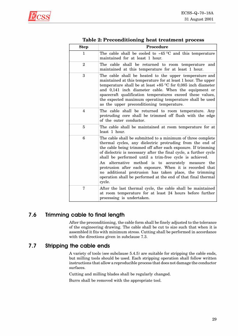
Table 2: Preconditioning heat treatment processStep Procedure
1 The cable shall be cooled to --45 ºC and this temperaturemaintained for at least 1 hour.
2 The cable shall be returned to room temperature andmaintained at this temperature for at least 1 hour.
3 The cable shall be heated to the upper temperature andmaintained at this temperature for at least 1 hour. The uppertemperature shall be at least +85 ºC for 0,085 inch diameterand 0,141 inch diameter cable. When the equipment orspacecraft qualification temperatures exceed these values,the expected maximum operating temperature shall be usedas the upper preconditioning temperature.
4 The cable shall be returned to room temperature. Anyprotruding core shall be trimmed off flush with the edgeof the outer conductor.
5 The cable shall be maintained at room temperature for atleast 1 hour.
6 The cable shall be submitted to a minimum of three completethermal cycles, any dielectric protruding from the end ofthe cable being trimmed off after each exposure. If trimmingof dielectric is necessary after the final cycle, a further cycleshall be performed until a trim-free cycle is achieved.An alternative method is to accurately measure theprotrusion after each exposure. When it is recorded thatno additional protrusion has taken place, the trimmingoperation shall be performed at the end of that final thermalcycle.
7 After the last thermal cycle, the cable shall be maintainedat room temperature for at least 24 hours before furtherprocessing is undertaken.
7.6 Trimming cable to final lengthAfter the preconditioning, the cable form shall be finely adjusted to the toleranceof the engineering drawing. The cable shall be cut to size such that when it isassembled it fits with minimum stress. Cutting shall be performed in accordancewith the directions given in subclause 7.3.
7.7 Stripping the cable endsA variety of tools (see subclause 5.4.5) are suitable for stripping the cable ends,but milling tools should be used. Each stripping operation shall follow writteninstructions that allow a reproducible process that doesnot damage the conductorsurfaces.
Cutting and milling blades shall be regularly changed.
Burrs shall be removed with the appropriate tool.

ECSS31 August 2001ECSS--Q--70--18A
30
7.8 Inspection of stripped cable endsEach of the stripped ends shall be subject to quality control inspection. Thereshall be no metal or foreign particles on the face of the dielectric. The outerconductor shall contain no burrs or major surface defects and shall be flush withthe dielectric. Unremoved dielectric near the centre conductor not exceeding0,2 mm is acceptable. The length of the wire inner conductor is dependent on theconnector type and shall be specified.
Typical control documentation for cable prior to assembly with SMA connectorshaving separate pin contacts shall include measurements of the parametersshown in Figure 4.
Remove burrs
Dielectric
Outer conductor
0,2 mm max. unremoved dielectric is acceptable
Centre conductor
Figure 4: Typical dimensional inspection requirements

ECSS 31 August 2001
ECSS--Q--70--18A
31
8
Preparation for soldering assembly of semi-rigid
cables
8.1 GeneralWritten procedures shall define the various process steps and shall include thefollowing subclauses.
8.2 Degolding and pretinningGold shall be removed from all surface areas to be joined by soldering. The centralcontact pin may be degolded and pretinned with a soldering iron by melting ashort length of 63 Sn or 60 Sn solder wire within the cup to dissolve gold plating;the liquid solder can then be wicked-out with stranded wire.
The jointing surface of the connector body shall be degolded and pretinned byfitting the connector to a suitable sized PTFE plug held vertically in a vice. Solderwire can be melted onto the jointing area and removed with the aid of a solderwick. This operation should be repeated at least twice until the solidified pre-tinned surface has a shiny appearance indicating a gold-free condition.
With the right-angle type of connector, the soldermounting surfaces of the inspec-tion/assembly cover and the corresponding surfaces of the body shall also bedegolded and pretinned before assembly.
The cable�s outer and inner conductors shall also be pretinned. The cable shall beallowed to cool to room temperature before checking it for possible dielectricprotrusion. Any protrusion shall be trimmed with a scalpel blade.
The fit of the pretinned cable in the connector shall be checked.
Activated fluxes should not be used, but they may be utilized for the degoldingand pretinning operations. If used they shall be removed immediately after thecable has returned to room temperature. There shall be no dewetting of the solderon the cable conductor or on the connector. All surfaces shall be cleaned with anapproved solvent (see subclause 6.3) until they are free from all residual flux andother visible contamination.
NOTE 1 The recommended degolding and pretinning temperaturesare 250 ºC to 280 ºC, and 210 ºC to 260 ºC, respectively,when using solder immersion.

ECSS31 August 2001ECSS--Q--70--18A
32
NOTE 2 Pretinning should be performed just before proceeding withthe assembly of the connector on the cable.
8.3 Solder preformsSome solder preforms with an internal diameter matching the outer diameter ofthe coaxial cable are available as prefluxed continuous rings. Alternatively,solder preforms may be prepared by winding 96 Sn solder wire around mandrelshaving the same outer diameter as the coaxial cable (0,085 or 0,141 inches). Thediameter of the wire and the number of turns are dependent on the type ofconnector and shall be predetermined by trials. As many preforms are made asthe number of connectors to be soldered. A scalpel blade shall be used to cut solderturns in a direction perpendicular to the wire wrap, as shown in Figure 5. Beforeuse, the preforms shall be thoroughly cleaned with one of the solvent cleanersspecified in subclause 6.3
Figure 5: Method of producing solder preforms

ECSS 31 August 2001
ECSS--Q--70--18A
33
9
Assembly of connectors to RF coaxial cables
9.1 Solder assembly of semi-rigid cables
9.1.1 Straight cable-end connector
9.1.1.1 Centre contact assembly
The centre contact shall be slid onto the prepared centre conductor of the cablewith an easy sliding fit. The centre conductor shall be visible across the fulldiameter of the inspection hole. The gap between the rear/end of the centrecontact and the face of the dielectric/outer conductor shall be as specified in theassembly instructions for the type of cable-end connector being used (seeFigure 6).
Inspection hole
Gap to be as specified in theconnector assembly instructions
Figure 6: Centre contact assembly
The centre contact shall be soldered to the centre conductor with the solderspecified in subclause 6.1 and the equipment specified in subclause 5.4.7. Afterthe solder has solidified and cooled, the joint shall be thoroughly cleaned with oneof the solvent cleaners specified in subclause 6.3.
After soldering, the gap between the centre contact and the face of the dielectric/outer conductor shall be rechecked and the solder connection inspected againstthe following criteria:
a. The inspection hole shall be filled with solder.
b. The appearance of the solder joint shall satisfy the criteria given inECSS--Q--70--08A, Figure A--7.
c. There shall be no flux or other residues on the cable or the contact.

ECSS31 August 2001ECSS--Q--70--18A
34
d. There shall be no solder spillage or flow onto the mating surfaces of thecontact.
e. Where any solder flow or spillage has occurred on the non-mating outersurfaces of the contact, it shall not cause the effective contact dimensions toexceed those specified for successful connector assembly.
9.1.1.2 Connector-body/cable assembly
The remaining connector parts shall be assembled to the cable in the followingsequence:
a. Slide any cable identification and other sleeves onto the cable in the sequencedefined by the cable assembly or layout drawings or specifications.
b. In the case of a straight cable-end connector, slide the coupling nut onto thecable with the internal thread facing the end of the cable to which theconnector is being assembled.
c. Slide the solder pre-form (if used) onto the cable.
d. Assemble the body of the connector to the centre contact and the end of thecable. This assembly should be with an easy sliding fit in both cases (centrecontact and pretinned outer conductor fitting).
At this stage the dimensional relationships of the connector body to the centreconductor and the correct full insertion of the cable outer conductor into theconnector body should be checked.
The outer conductor of the cable shall be soldered to the body of the connector withthe solder specified in subclause 6.1 and the equipment specified in subclause5.4.7. After the solder has solidified and cooled the joint shall be thoroughlycleaned with one of the solvent cleaners specified in subclause 6.3.
9.1.1.3 Inspection of assembly
After soldering and cleaning, the assembly of the connector to the cable shall beinspected against the following criteria:
a. The dimensional relationship of the centre contact and body of the connectorshall be correct.
b. The appearance of the outer conductor to connector body solder joint shallsatisfy the visual criteria given in ECSS--Q--70--08A, annex A.
c. There shall be no solder flow or other residues on the cable or connector.
d. There shall be no solder flow or spillage onto the mating surfaces of theconnector or onto the shoulder of the connector body where it interfaces withthe coupling nut.
e. Any other solder flow or spillage onto the body of the connector shall not affectthe operation of the coupling nut.
f. There shall be no solder spillage or other contamination on the coupling nut.
9.1.2 Right angle cable-end connectorThe connector shall be assembled to the cable-end according to the followingsequence of operations:
a. After preconditioning (as defined in subclause 7.5), the cable-end shall be cutto the dimensions necessary for correct fitting to the connector as shown inFigure 7. It shall then be degolded and pretinned as defined in subclause 8.2.
b. Prepare the connector by degolding the bifurcated pin, the seating for thecover and the cover.
c. The cable shall be inserted into the connector and the assembly (cable andconnector) held in a suitable fixture to ensure that the angular relationshipbetween preformed cable and connector is correct. The insertion of the cable

ECSS 31 August 2001
ECSS--Q--70--18A
35
into the connector shall be inspected via the inspection/assembly hole toensure that it is in conformance with Figure 7.
d. The solder joint between the inner conductor of the cable and the bifurcatedpin of the connector shall be made first, with the aid of a fine soldering ironand the solder defined in subclause 6.1. After the solder has solidified andcooled, the centre-conductor solder joint and the cavity in the connector bodyshall be thoroughly cleaned with one of the solvent cleaners specified insubclause 6.3. The solder joint shall be inspected to ensure that full insertionof the inner conductor of the cable into the bifurcated pin of the centreconductor of the connector has taken place (see Figure 7) and in order tosatisfy the inspection requirements of ECSS--Q--70--08A, clause 12.
e. The outer conductor of the cable shall now be soldered to the body of theconnector with the aid of the solder specified in subclause 6.1 and the equip-ment specified in subclause 5.4.7. After the solder has solidified and cooled,the joint shall be thoroughly cleaned with one of the solvent cleaners speci-fied in subclause 6.3.
f. The solder joints between the cable and the connector shall be inspected toensure that the dimensions of the cable-connector interface still conform toFigure 7 and that the solder joints conform to the inspection requirementsof ECSS--Q--70--08A, clause 12.
g. The cover shall now be assembled to the inspection/assembly hole and thesolder joint formed with a soldering iron using the solder specified in sub-clause 6.1. Extra solder shall not be added during this operation; the jointshall rely on reflowing of the solder applied during the degolding/pretinningoperation only. This is to prevent the flow of excess solder into the cavity inthe connector body. After the solder has solidified and cooled, the joint shallbe thoroughly cleaned with one of the solvent cleaners specified in subclause6.3.
h. The cover solder joint shall be inspected with respect to the following criteria:
1. The solder joint shall extend around the complete periphery of the cover.
2. The cover shall be fully inserted into the shoulder of the hole (see Fig-ure 7).
3. The solder joint shall conform to the inspection requirements ofECSS--Q--70--08A, clause 12.

ECSS31 August 2001ECSS--Q--70--18A
36
see Note 3 see Note 1
see detailbelow andNote 2
see Note 4
Teflon plug
Copper sheath
PTFE dielectric
Solder joint
Detail of cable inner conductor inserted into bifurcatedend of inner contact of connector
Note 1The cable is inserted into theconnector body so that the outerconductor and PTFE dielectric areflush with the inner wall of theconnector cavity.
Note 2With the cable inserted asdescribed in Note 1, the innerconductor is fully inserted into thebifurcated end of the inner contactof the connector.
Note 3Cover fully inserted and solderedinto shoulder of connector cavity.
Note 4Captive-type coupling nut (seeFigure 3). Taking care to avoidstress during cable mounting.
Figure 7: Right angle cable--end connector assembly

ECSS 31 August 2001
ECSS--Q--70--18A
37
9.2 Crimp assembly of semi-rigid cables and other assemblytechniques
The connectors and cables shall be assembled in accordance with formally docum-ented and qualified processes and procedures. These processes and proceduresshall be subject to formal acceptance by the customer. This acceptance can involvea customer audit of the facilities, processes and procedures used for assemblingthe cables and connectors. The final stage of assembly shall be a thorough inspec-tion covering dimensional conformance, cleanliness, lack of damage and qualityof the assembly techniques used.
9.3 Completed assembliesWhen the assembly of the cable and connectors is complete, it shall be inspectedto ensure that it is dimensionally correct (i.e. in accordance with the layoutdrawing or jig) and clean (e.g. free from contaminants, particles and burrs).
The completed and inspected cable assembly shall have protective caps fitted overthe connectors. The cable shall be stored in an adequate container inside a sealedbag with an inert atmosphere. The storage packaging shall be adequate to protectthe cable against deformation, damage and contamination.
Where the completed cable is transported to the user, an adequate shippingcontainer shall be provided to give the necessary additional protection to thestorage packaging.
Where for thermal or other reasons the cable assembly is painted, the paint shallbe applied to the outer conductor of the cable only and shall stop at least 5 mmbefore the joint to the connector (e.g. solder fillet and crimp ferrule 2)). The paintused shall conform to the requirements of ECSS--Q--70--02A, clause 7. The con-nectors shall not be painted.
2) Crimping is covered in ECSS--Q--70--26.

ECSS31 August 2001ECSS--Q--70--18A
38
(This page is intentionally left blank)

ECSS 31 August 2001
ECSS--Q--70--18A
39
10
Mounting of cables
10.1 Semi-rigid cables with straight solder-type connectorsThe following mounting sequence shall be followed:
a. The assembled cable shall be removed from its storage packaging only whenit is needed for immediatemounting. After removal from the storage packag-ing, the cable assembly shall be fully inspected before mounting. Ensure thatthe mating surfaces and screw threads are clean and free from damage.
b. The connector coupling nuts shall be retracted along the cable until they areat least 1 cm clear of the relevant connector body.
c. The connector inner contacts shall be inserted into the relevant receptaclesin the mating halves and slid home so that the mating faces of the bodies ofthe mating connectors are in contact. During this operation absolutely nolateral force shall be applied to correct misalignment of the cable-end con-nectors and the mating connectors. Longitudinal force may only be appliedin the case where the connectors mating with the cable are facing each other;the force shall be limited to that required to compress the cable temporarilyby the length of one connector inner contact mating face; the cable shall havegenerous stress relief bends which allow the temporary �compression� to be,in fact, a very slight temporary bending.
d. At the completion of the connector mating operation, the cable shall be lyingwithout external force, both cable-end connectors having the inner contactsfully inserted and the cable lying in contact with all support points.
e. The two connector coupling nuts shall now be loosely screwed onto the mat-ing connector bodies and tightened to the specified torque (this shall be asspecified for the particular connector, but should be in the range 0,8 Nm to1,1 Nm). During the nut mating and torquing operations, ensure that norotation of the cable-end connector body or of the cable takes place.
f. The cable shall now be secured to its support points (where applicable).
g. Any cable that cannot be installed according to theprocedure described aboveshall be rejected and a new cable provided to the correct dimensions.

ECSS31 August 2001ECSS--Q--70--18A
40
10.2 Semi-rigid cables with right-angle connectorsThe following mounting sequence shall be followed:
a. Unpacking and inspection as defined in subclause 10.1 a. above.
b. The cable-end connectors shall be aligned with their mating connectors sim-ultaneously and the centre contacts aligned with their mating receptacles.During this operation absolutely no lateral force shall be applied to correctmisalignment of the cable-end connectors and the mating connectors.
c. The connector coupling nuts shall be screwed onto the mating connectorbodies until finger-tight, then unscrewed 1/4 turn. In this condition the cableshall be resting in contact with its support points (where applicable), butshall be free to move within the constraint given by the 1/4 turn loosening ofthe connectors.
d. The connectors shall now be finger-tightened and torqued to the specifiedfigure for the particular connector (the torque should be in the range 0,8 Nmto 1,1 Nm). During the nut mating and torquing operations, ensure that norotation of the cable-end connector body or of the cable takes place.
10.3 Other cable mounting technologiesThe mounting requirements for other technologies should be defined by thesuppliers of the connectors, cables or assemblies. Special attention shall be paidto the following points:
a. Stress-free mounting of assembled cables to the interfacing connectors shallbe used everywhere.
b. For each technology, the bend-radius constraints for the particular type ofcable shall be respected.
c. The cable-support requirements for the particular type of cable shall berespected. Particularly in the case of flexible cables having an expanded typeof dielectric, the cable clamps should be of a carefully designed rigid type thatenables any forces resulting from vibration to be distributed over a signifi-cant length of the cable. This shall be done to avoid local dielectric crushingand, hence, degradation of electrical performance.

ECSS 31 August 2001
ECSS--Q--70--18A
41
11
Process verification
11.1 GeneralVerification tests shall be conducted to establish confidence in the reliability ofsolder-joint configurations and processing methods not shown in this Standard.The configuration is considered verified if no cracked solder joints or part damageis found after 200 thermal cycles in accordance with the test conditions given insubclause 11.2 and when the configuration is examined under 15× minimummagnification. The absence of cracks within the interconnection shall be ascer-tained bymetallography, microsections being made in the longitudinal mid-planeof the assembly.
11.2 Temperature cyclingThe test specimen shall be temperature cycled in an air-circulating oven fromroom temperature to --55 ºC to +100 ºC and back to room temperature at a ratenot exceeding 10 ºC per minute. The temperature extremes may be increased toactual spacecraft qualification temperatures if these exceed the range --55 ºC to+100 ºC. Soak time at each temperature extreme should be 15 minutes. Theduration of each cycle should average one hour. These conditionsmay bemodifiedby the customer to conform with the particular environmental qualificationconditions for the assembly being verified.
11.3 VibrationAfter completion of the temperature cycling, the test specimen shall be subjectedto vibration. The test levels, frequencies and durations shall be derived from the

ECSS31 August 2001ECSS--Q--70--18A
42
system requirements, but the severity of the vibration tests shall not be inferiorto that shown in Table 3.
Table 3: Minimum severity for vibration testingFrequency range 10 Hz -- 2000 Hz at 15 g
Sinevibration
Vibrationamplitude
(peak to peak) 10 Hz -- 70 Hz at 1,5 mm
vibrationSweep speed 1 octave per minute
Duration 1 cycle from 10 Hz -- 2000 Hz -- 10 Hz
Frequency range 20 Hz -- 2000 Hz at 15 g (r.m.s.)
Randomvibration
Power spectraldensity
0,1 g2/Hz
Duration 10 minutes per axis
ECSS 31 August 2001
ECSS--Q--70--18A
43
12
Quality assurance
12.1 GeneralThe quality assurance requirements are defined in ECSS--Q--20.
12.2 DataThe quality records (e.g. logbooks) shall be retained for at least ten years, or inaccordance with project contract requirements, and contain, as a minimum, thefollowing:
D copy of final inspection documentation;
D nonconformance reports and corrective actions;
D copy of the inspection and test results with reference to the relevant pro-cedure, drawings, personnel, tools, solders, fluxes and solvents utilized.
12.3 NonconformanceAny nonconformance observed in respect of the soldering process shall be disposi-tioned in accordance with quality assurance requirements (see ECSS--Q--20--09).If a repair procedure is agreed, it shall be performed in accordance withECSS--Q--70--28.
12.4 CalibrationEach insulation stripper, soldering iron, piece of measuring equipment and refer-ence standard shall be periodically calibrated. Any suspected or actual equipmentfailure shall be recorded as a project nonconformance report so that previousresults can be examined to ascertain whether or not re-inspection or retesting isrequired. The final customer shall be notified of the nonconformance details.
12.5 TraceabilityTraceability shall be maintained throughout the process from incoming inspec-tion to final test, including details of test equipment and personnel employed inperforming the task.
12.6 Workmanship standardsVisual standards consisting of satisfactory work samples or visual aids that clear-ly illustrate the quality characteristics of all soldered connections involved shall

ECSS31 August 2001ECSS--Q--70--18A
44
be prepared and shall be available to each operator and inspector. The illustra-tions presented in annex A of this Standard, supplemented as necessary, shall beincluded as examples.
12.7 InspectionDuring all stages of the process, the inspection points shall be observed.
12.8 Operator and inspector training and certificationTrained and competent personnel shall be employed for all soldering and crimp-ing operations and inspections. A training programme shall be developed, main-tained and implemented to provide for excellence of workmanship and personnelskills and a thorough knowledge of the requirements detailed in this Standard.
Trained personnel performing soldering and crimping operations and inspectionsshall be certified. This certification shall be based upon objective evidence ofquality, resulting from test and inspection of completed joints. Retraining orreassessment of personnel shall apply in cases of repetitive unacceptable qualitylevels and changes in soldering or assembly techniques, parameters or requiredskills.
Records shall be maintained of the training and certification status of operatorsand inspection personnel.
All training shall be performed at a school authorized by the final customer.

ECSS 31 August 2001
ECSS--Q--70--18A
45
Annex A (informative)
Workmanship standards
A--A--
Figure A--1: Photograph showing non-captive nut and preferredsolder fillet
Figure A--2: Microsection through preferred solder fillet,revealing full penetration of solder path
Excessive fillet height
Insufficient fillet length
Figure A--3: Unacceptable solder fillet dimensions

ECSS31 August 2001ECSS--Q--70--18A
46
(This page is intentionally left blank)

ECSS 31 August 2001
ECSS--Q--70--18A
47
ECSS Document Improvement Proposal1. Document I.D.ECSS--Q--70--18A
2. Document date31 August 2001
3. Document titlePreparation, assembly andmounting of RF coaxialcables
4. Recommended improvement (identify clauses, subclauses and include modified text orgraphic, attach pages as necessary)
5. Reason for recommendation
6. Originator of recommendation
Name: Organization:
Address: Phone:Fax:e-mail:
7. Date of submission:
8. Send to ECSS Secretariat
Name:W. KriedteESA--TOS/QR
Address:ESTEC, P.O. Box 2992200 AG NoordwijkThe Netherlands
Phone: +31--71--565--3952Fax: +31--71--565--6839e-mail: [email protected]
Note: The originator of the submission should complete items 4, 5, 6 and 7.This form is available as a Word and Wordperfect-file on internet under
http://www.estec.esa.nl/ecss

ECSS31 August 2001ECSS--Q--70--18A
48
(This page is intentionally left blank)